Embed Size (px)
Citation preview
OPERATION &
MAINTENANCE MANUAL
E-Type Electronic Table -Top Autoclaves models 1730, 2340, 2540, 3140, 3850,3870
E, EK, EA & EKA
Cat. No. MAN205-0001 Rev. E Tuttnauer Europe b.v., P.O. Box 7191, 4800GD Breda, The Netherlands. + 31/76-5423510 Tuttnauer USA Co. 25 Power Drive Hauppauge, NY, 11788, USA (800) 624 5836, (631) 737 4850, Fax: (631) 737 07 20
Email: [email protected]
1
TABLE OF CONTENTS PARAGRAPH PAGE NO. 1 GENERAL.............................................................................................................4
1.1 Incoming Inspection ................................................................................4 1.2 Warranty...................................................................................................4 1.3 Warranty Statement .................................................................................4
2 TECHNICAL DATA.............................................................................................6 2.1 Introduction..............................................................................................6 2.2 Stand – by heating mode..........................................................................6 2.3 Operating Conditions...............................................................................7 2.4 Utilities......................................................................................................7 2.5 Environment Emission Information .......................................................7 2.6 Electrical Data: ........................................................................................7 2.7 Specifications ...........................................................................................8 2.8 Technical Specifications (for E, EK, EA, EKA models) ........................9 2.9 Construction ...........................................................................................10 2.10 Directives and Standards .......................................................................10 2.11 Water quality ..........................................................................................11 2.12 Symbol Description ................................................................................12
3 STERILIZATION PROGRAMS ........................................................................15 3.1 Program 1 (134ºC with no drying) .......................................................15 3.2 Program 2 (121ºC with no drying) .......................................................16 3.3 Program 3 (134ºC with drying) ............................................................17 3.4 Program 4 (121ºC with drying) ............................................................18 3.5 Program 5 (121ºC with slow exhaust)..................................................19
4 KEYBOARD (keys and display) .........................................................................20 4.1 Description and Functions of the Front Panel Keyboard....................21 4.2 Description of the Operational Messages .............................................24 4.3 Description of Displayed Error Messages and Safety Measures .........26
5 PRINTER ............................................................................................................28 5.1 Printer Operation ...................................................................................28 5.2 Printer Handling ....................................................................................30
6 INSTALLATION PLACING AND LEVELING INSTRUCTIONS .................31 6.1 leveling....................................................................................................31 6.2 Water quantity for a cycle......................................................................32 6.3 Lifting and carrying ...............................................................................32 6.4 Loading and unloading the Device .......................................................32 6.5 Filling the Water Reservoir ...................................................................33
7 PREPARATION BEFORE STERILIZATION .................................................34 8 OPERATING INSTRUCTIONS ........................................................................38
2
TABLE OF CONTENTS (Cont.) PARAGRAPH PAGE NO. 9 MAINTENANCE INSTRUCTIONS..................................................................40
9.1 Preventive and Scheduled Maintenance ...............................................40 9.2 Draining the Reservoir...........................................................................41 9.3 Cleaning Air Jet .....................................................................................42 9.4 Replacing the Door Gasket ....................................................................43 9.5 Replacing the Air Filter (models EA, EKA) .........................................44 9.6 Cleaning water outlet strainer ...............................................................45 9.7 Replacing the Cartridge Fuse................................................................46 9.8 Checking the Safety Valve .....................................................................47 9.9 Door Safety System ................................................................................48 9.10 Cleaning Table Top Autoclaves with Chamber Brite™.......................49
10 TROUBLESHOOTING ..................................................................................51 11 ACSSESORIES LIST .....................................................................................57 12 SPARE PARTS LIST......................................................................................57
3
TABLE OF CONTENT (Cont.)
DRAWINGS PAGE NO. Front View...................................................................................................................13 Rear View ....................................................................................................................14 Front Panel Keyboard.................................................................................................20 Pouch Rack .................................................................................................................54 Tray..............................................................................................................................55 Tray handle CMT240-0001 ........................................................................................55 Tray holder ..................................................................................................................56 Alternative tray holder ................................................................................................56
4
1 GENERAL Read the Operating Instructions carefully, before beginning any operation
on the autoclave!
1.1 Incoming Inspection The autoclave should be unpacked and inspected for mechanical
damage upon receipt. Observe packing method and retain packing materials until the unit has been inspected. Mechanical inspection involves checking for signs of physical damage such as: scratched panel surfaces, broken knobs, etc.
If damage is apparent, contact your dealer or point of purchase, so that they may notify the manufacturer and file a claim with the appropriate carrier.
All Tuttnauer products are carefully inspected prior to shipment and all reasonable precautions are taken in preparing them for shipment to assure safe arrival at their destination.
1.2 Warranty We certify that this instrument is guaranteed to be free from defects in
material and workmanship for one year against faulty components and assembly with the exception of glassware, lamps and heaters.
The warranty does not include and does not replace routine treatment and preventive maintenance to be performed according to instructions in paragraph 9.1 (Preventive and Scheduled Maintenance).
Our obligation is limited to replacing the instrument or parts, after our
examination, if within one year after the date of shipment they prove to be defective. This warranty does not apply to any instrument that has been subjected to misuse, neglect, accident or improper installation or application, nor shall it extend to autoclaves that have been repaired or altered by an un-authorized person.
The Autoclave should not be used in a manner not described in this manual!
1.3 Warranty Statement The warranty registration must be completed and returned to our
service departments; within fourteen (14) days of purchase or the warranty will be void.
Our Technical Service Depts can be reached at: Tuttnauer Europe b.v., Paardeweide 36, P.C. Box 7191,
4800GDBreda, Netherlands. +31/76-5423510, Fax: +31/76-5423540, E-mail: [email protected]
Tuttnauer USA Co. 25 Power Drive Hauppauge, NY, 11788, USA
(800) 624 5836, (631) 737 4850, Fax: (631) 737 07 20 Email: [email protected]
Rudolf Gunz & Co. PTY LTD: Service Department, 26-34 Dunning Avenue, Ros, 2018, Sydney,
Australia. Service Department, Locked bag 690, Beaconsfield, NSW 2014,
Australia. +61-2-99356600 Fax: +61-2-99356650

5
Note: If there is any difficulty with this instrument, and the solution is not
covered in this manual, contact our representative or us first. Do not attempt to service this instrument yourself. Describe the difficulty as clearly as possible so we may be able to diagnose the problem and provide a prompt solution.
If the autoclave is equipped with a printer, send along a copy of the last printout for our inspection. If replacement parts are needed, stipulate the model and serial number of the machine.
No autoclaves will be accepted for repair without proper authorization from us. All transportation charges must be paid both ways by the owner. This warranty will be void if the unit is not purchased from an authorized full service Tuttnauer dealer.
6
2 TECHNICAL DATA 2.1 Introduction This E-Type table-top autoclave is designed for the sterilization of
medical and surgical solid instruments in dental, medical and veterinary clinics, first aid rooms, laboratories etc.
Types E and EK are intended to sterilize non wrapped solid products. Types EA and EKA are intended for sterilization of non-wrapped and
wrapped solid products. The autoclave models E, EK, EA and EKA are electrically - heated
sterilizers of different dimensions, using steam as the sterilizing agent. A computerized control unit ensuring a fully automatic sterilization cycle and precise control and monitoring of physical parameters and a clear documentation of the sterilization cycle controls the autoclave.
Five automatic programs are available, according to the material to be sterilized. All sizes (except 1730) have a model that includes a drying stage (EA and EKA). The difference between EK and EKA is the air compressor that, during the drying stage, pushes filtered air (0.2µm.) through the chamber to pull out the humidity, the dry operation is performed with the door closed.
On all models (except 1730), a water pump is installed between the water reservoir and the chamber. This pump intensifies the water flow into the chamber. Entry of water may be accompanied by a noise for approximately 30 seconds. This is normal noise generated by regular operation of the pump.
The control system provides adequate protection, to ensure the safety of personnel and reliable operation with a minimum of shut down time.
All models (except 1730) are equipped with a pressure gauge that is used as a guide only. Should there be a power failure during the operation of the autoclave, the pressure gauge indicates to the operator that there is pressure in the chamber. The accuracy is ± 1.6%.
On all models (except 1730), a printer is an optional addition to the autoclave. The printer prints the preset and actual parameters of the cycle (temperature, time and pressure/vacuum).
This manual is intended for the user and gives the user a general understanding of the instrument and the best ways to operate and take care of it in order to obtain optimum effective results.
After reading this manual, operating the autoclave will be easy. However since this instrument is built with high technology sensitive components, no attempt should be made by the user or any other unauthorized person to repair or recalibrate it.
Only technical personnel having proper qualifications and holding technical documentation (including a technician manual) and adequate information are authorized to service the apparatus.
2.2 Stand – by heating mode The autoclave provides an option of heating the chamber in stand-by
mode between cycles with a very low power in order to reduce total cycle time (1.6% of the total power only). The autoclave turns off automatically if the interval between the sterilization cycles is more than 2 hours. The stand-by feature is activated, as default, on cycles 1, 2, 3, 4 and not activated on cycle 5.
7
The company – qualified technician can cancel this feature on EK or EKA models, or activate it on E and EA models, according to customer requirements.
2.3 Operating Conditions This device is for indoor use only! The sterilizer should be loaded only with autoclavable material! The environment shall not exceed an ambient temperature of 40ºC and
a relative humidity of 85% respectively.
Caution! Waste water should be brought into the public net in accordance with the local rules or requirements i.e. ONLY NON-HAZARDOUS LIQUIDS SHALL BE DISPOSED IN PUBLIC SEWAGE!
2.4 Utilities
Utility Unit Value
V-A 1ph, 230/240V – 16A, 50 HzPower supply (as appropriate)
V-A 1ph, 120V – 16A, 60 Hz
Attention: The electrical net must be protected with a current leakage safety relay. The electrical network must comply with local rules or regulations.
2.5 Environment Emission Information
1. The peak sound level generated by the autoclave is less than 70 dBA with background noise of 60 dBa.
2. The total heat per hour transmitted by the autoclave is < 100 Wh for all models.
2.6 Electrical Data:
1730 2340 2540 3140 3850 3870
E EK E, EA EK, EKA E, EA EK,
EKA E, EA E, EA E, EA
Ampere (A) at 230/240V 4.6 5.9 6 9.6 6 9.6 10.4 10.4 13
Ampere (A) at 120V 8.8 11.2 11.7 11.7 20.0
Watts (W) 1050 1350 1400 2200 1400 2200 2400 2400 3000
Frequency 50 / 60 Hz
Protection against electrical shock Class I (IEC 60601-1)
8
2.7 Specifications
Overall Dimensions
1730 2340 2540 3140 3850 3870 Model Dimensions mm in mm in mm in mm in mm in mm in
A 440 17.4 510 20.0 510 20.0 590 23.2 660 26.0 660 26.0
B 305 12.0 365 14.4 365 14.4 450 17.7 525 20.7 525 20.7Overall Dimensions
C 455 17.9 545 21.5 545 21.5 566 21.9 695 27.5 875 34.5
D 750 29.5 900 35.8 900 35.8 990 39.0 1155 45.5 1335 53.0Maximum dimensions (door open) E 560 22.0 655 25.8 655 25.8 755 29.7 815 32.0 815 32.0
F 350 13.8 415 16.4 415 16.4 488 19.2 450 2.0 450 2.0
F1 339 13.4 422 16.6 422 16.6 371 14.6 564 22.2 564 22.2
G 50 2.0 50 2.0 50 2.0 50 2.0 50 2.0 50 2.0
Distance between supporting legs F1 - front legs F - rear legs
H 315 12.4 400 15.8 400 15.8 400 15.8 555 2.0 725 2.0
Chamber diameter 170 6.7 230 9.1 254 10.0 312 12.3 384 15.1 384 15.1
Depth 340 13.4 470 18.5 475 18.7 475 15.4 580 22.8 760 29.9
Reservoir volume 3.0 lit.
0.8 gal
3.0 lit.
0.8 gal
3.0 lit.
0.8 gal
3.0 lit.
0.8 gal
6.0 lit.
1.6 gal
6.0 lit.
1.6 gal
Minimum water vol. in Reservoir
0.8 lit.
0.21 gal
0.8 lit.
0.21gal
0.8 lit.
0.21gal
0.8 lit.
0.21gal
2.0 lit.
0.53 gal
2.0 lit.
0.53gal
Max. Allowable Working Pressure (MAWP)
2.76 bar (40 psi)
Load No. counter Counting from 0 to 3000 and nullifies.
9
0.76
m3
(26.
8cu.
f)
0.63
m3
(22.
2cu.
f.)
0.35
m3
(12.
4cu.
f.)
0.27
m3
(9.4
cu.
f.)
0.27
m3
(9.4
cu.
f.)
0.18
m3
(6.3
5 cu
.f.)
Ship
ping
V
olum
e
102
kgs.
(225
lbs.)
89 k
gs.
(196
lbs.)
60 k
gs.
(132
lbs.)
48 k
gs.
(106
lbs.)
36 k
gs.
(79
lbs.)
25 k
gs.
(55
lbs.)
Ship
ping
W
eigh
t
Yes
Yes
Yes
Yes
Yes
N/A
Prin
ter
—
—
4 3 2 —
Full
15
10
4 3 2 2 Hal
f
No.
of s
tand
ard
Cas
sett
es (O
ptio
nal)
2 2 2 4 3 3 No.
o
f tra
ys
28 x
67
x 2.
5cm
( 1
1" x
26"
x 1
" )
35 x
67
x 2.
5 (1
4" x
26"
x 1
")
28 x
50
x 2.
5 cm
(1
1" x
20
" x
1" )
35 x
50
x 2.
5cm
(1
4" x
20
" x
1")
25.6
x 4
0.8
x 2.
5 (1
0.1
x 16
.1 x
1)
19.8
x 4
0.8
x 2.
2 (7
.8 x
16.
1 x
1)
17 x
41.
5 x
2 cm
(6
.7"
x 16
.3"
x0.8
")
17 x
41.
5 x
2cm
(6
.7"
x 16
.3"
x 0.
8")
12 x
29.
5 x
2 cm
(4
.7"
x 11
.6"
x 0.
8")
Tra
y di
men
sion
s W
X D
X H
84 li
ters
(2
2 U
S ga
l)
65 li
ters
(1
7US
gal)
34.4
lite
rs
(7.8
US
gal.)
23 l.
(6
US
gal.)
19 li
ters
(5
US
gal.)
7.5
liter
s (2
US
gal.)
Vol
ume
of
usab
le
spac
e
38x7
6 cm
(1
5" x
30"
)
38 ×
58
cm.
(15"
× 2
3" )
31.2
x 3
9.1
(2.3
” x
15.4
”)
25.4
x 4
7.5c
m
(10"
x 1
8.7"
)
23 x
47
cm
(9"
x 18
.5")
17 x
34
cm
(6.7
" x
13.4
")
Cha
mbe
r di
men
sion
s D
IA x
D
3870
3850
3140
2540
2340
1730
Mod
els 2.8
Tech
nica
l Spe
cific
atio
ns (f
or E
, EK
, EA
, EK
A m
odel
s)
10
2.9 Construction The main parts of the autoclave are made of materials as indicated
below: ♦ Chamber is electro-polish and built of stainless steel 316 L. ♦ Door is made of stainless steel CF8. ♦ Trays are made of stainless steel 316. ♦ Water reservoir is made of hard plastic material. ♦ Door handle is made of hard plastic material, which is safe to
touch and thermo-insulated. ♦ Covers are made of aluminum sheet, coated with Epoxy paint.
2.10 Directives and Standards Every autoclave meets the provisions of the following Directives and is
constructed in compliance with the following Standards:
2.10.1 Technical Directives
1. Medical device directive MDD/93/42/EEC.
2.10.2 Technical Standards 1. A.S.M.E. Code, section VIII division 1 for pressure
vessels. 2. EN 61010-1:93 – Safety of electrical equipment
…General requirement. 3. EN 61010-2-041:97 – Particular requirement for steam
autoclaves. 4. EN 50081-1:92 – (EMC) Emission compatibility… 5. EN 50082-1:97 – (EMC) Immunity compatibility…. 6. prEN 13060-1:97-General requirements for all types of
small steam sterilizers. 7. prEN 13060-3 and 4:97-Particular requirements and
test method for type N and S sterilizers.
2.10.3 Quality standards The manufacturing plant meets the following quality
standards: 1. EN ISO 9002 (7.94) – Quality System 2. EN 46002 (8.96) - Quality System - Medical device -
Particular requirements. 3. ISO 13488 – Quality systems – Medical devices –
Particular requirements for the application of ISO
9002. The manufacturer retains all supporting documentation.
11
2.11 Water quality 2.11.1 Water for generation of steam The distilled or mineral – free water supplied to the
autoclave should have the physical characteristics and maximum acceptable level of contaminants indicated in the table below:
Physical characteristics and acceptable contaminants
levels in water, for sterlizers
Evaporate residue < 15 mg/l
Silica < 2 mg/l
Iron < 0.2mg/l
Cadmium < 0.005 mg/l
Lead < 0.05 mg/l
Rest of heavy metals < 0.1 mg/l
Chloride < 3 mg/l
Phosphate < 0.5 mg/l
Conductivity < 50 µs/cm
pH 6.5 to 8
Appearance colourless, clean, without sediment
Hardness < 0.1 mmol/l
Compliance with the above data should be tested in accordance with acknowledged analytical methods, by an authorized laboratory.
Attention: We recommend testing the water quality once a month. The
use of water for autoclaves that do not comply with the table above may have severe impact on the working life of the sterilizer and can invalidate the manufacturer’s guarantee.
2.11.2 Reverse Osmosis A Reverse Osmosis (RO) system may be used to improve the
quality of the water used to generate steam in the steam generator.
In RO, the water is forced through a semi-penetrable membrane, which filters out contaminants to a high degree of efficiency. In deionisation (DI) ions and charged particles are removed either by electric fields or by ion exchange in resin beds.
Although the RO cannot normally attain the degree of purity possible with the DI methods, it is more than adequate for the feed water intended for clean-steam generators.
Moreover the RO has several advantages:
12
1. RO is cheaper to install and to run than DI. 2. RO removes particulate matter, organic molecules and pyrogens
that DI cannot remove 3. RO water is less corrosive to steel and copper than DI water. 4. RO maintenance requirements are less demanding than those of
the DI units. Therefore the use of mineral free water will contribute to better
performance and longer life of the autoclave. 2.12 Symbol Description
Caution! Consult accompanying documents
Caution! Hot surface.
Caution! Hot steam.
Protective earth (Ground)
Stand by
13
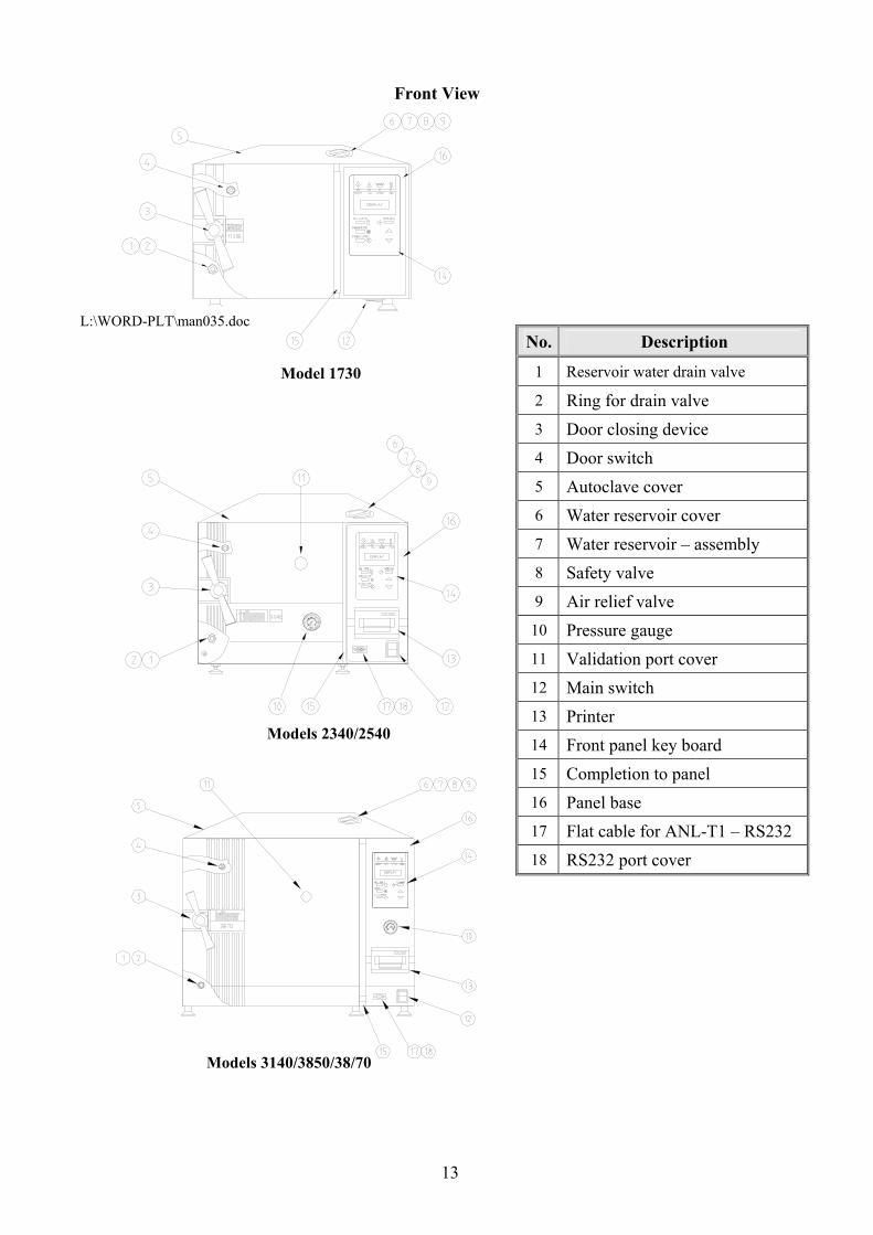
Front View
No. Description
1 Reservoir water drain valve
2 Ring for drain valve 3 Door closing device 4 Door switch 5 Autoclave cover 6 Water reservoir cover 7 Water reservoir – assembly 8 Safety valve 9 Air relief valve
10 Pressure gauge 11 Validation port cover 12 Main switch 13 Printer 14 Front panel key board 15 Completion to panel 16 Panel base 17 Flat cable for ANL-T1 – RS232 18 RS232 port cover
2.12.1.1.1.1
Model 1730
L:\WORD-PLT\man035.doc
Models 2340/2540
Models 3140/3850/38/70

14
Rear View
15
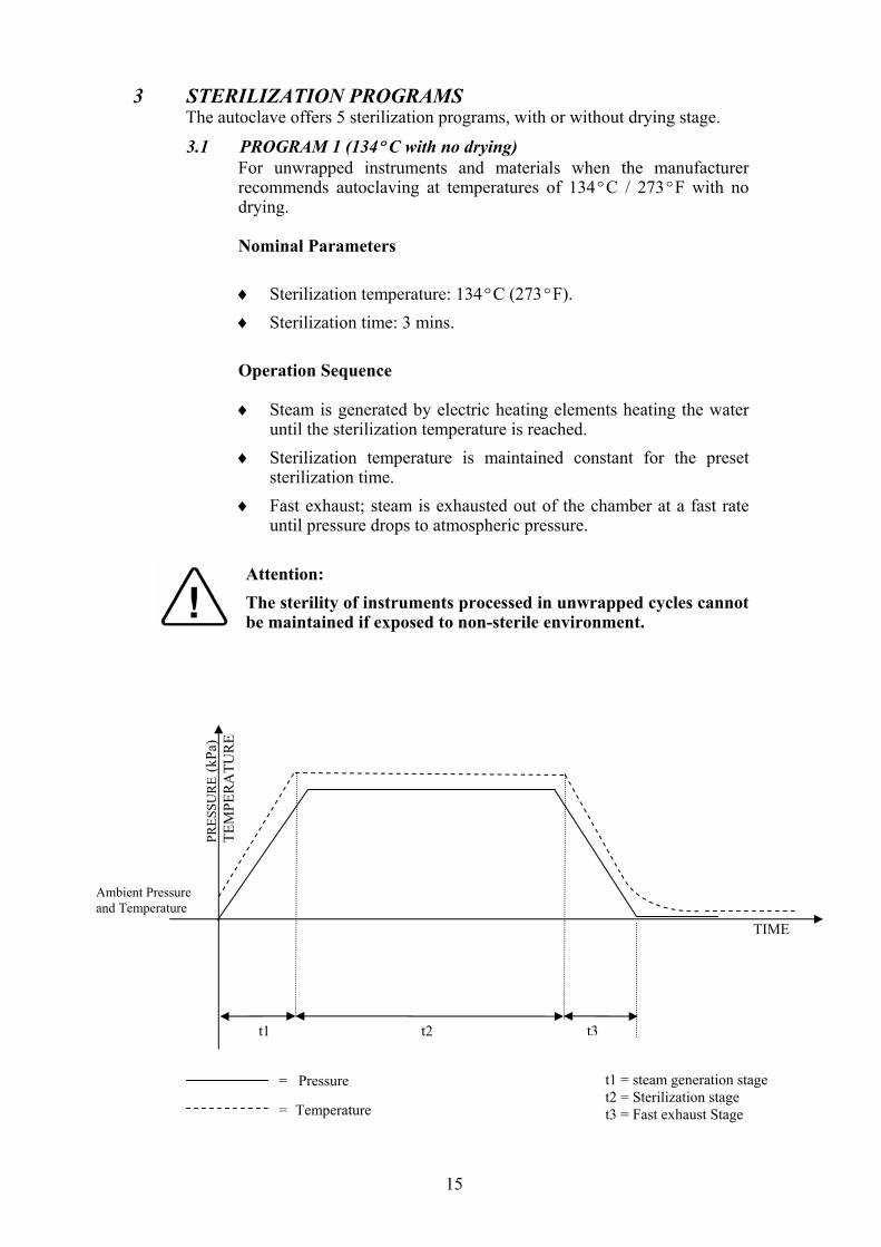
3 STERILIZATION PROGRAMS The autoclave offers 5 sterilization programs, with or without drying stage.
3.1 PROGRAM 1 (134ºC with no drying) For unwrapped instruments and materials when the manufacturer
recommends autoclaving at temperatures of 134ºC / 273ºF with no drying.
Nominal Parameters
♦ Sterilization temperature: 134ºC (273ºF). ♦ Sterilization time: 3 mins.
Operation Sequence
♦ Steam is generated by electric heating elements heating the water until the sterilization temperature is reached.
♦ Sterilization temperature is maintained constant for the preset sterilization time.
♦ Fast exhaust; steam is exhausted out of the chamber at a fast rate until pressure drops to atmospheric pressure.
Attention: The sterility of instruments processed in unwrapped cycles cannot be maintained if exposed to non-sterile environment.
TIME
PRES
SUR
E (k
Pa)
TEM
PER
ATU
RE
Ambient Pressure and Temperature
t1 t2 t3
t1 = steam generation stage t2 = Sterilization stage t3 = Fast exhaust Stage
= Pressure = Temperature
16
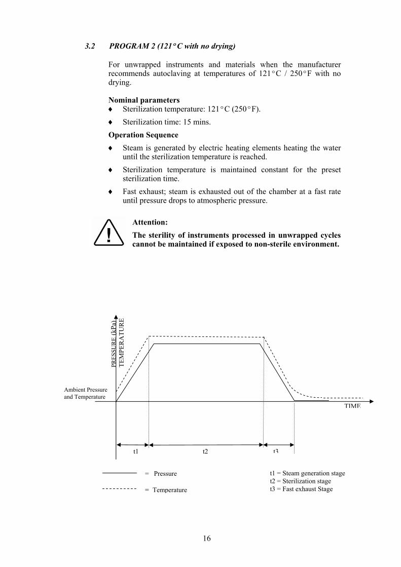
3.2 PROGRAM 2 (121ºC with no drying) For unwrapped instruments and materials when the manufacturer
recommends autoclaving at temperatures of 121ºC / 250ºF with no drying.
Nominal parameters
♦ Sterilization temperature: 121ºC (250ºF). ♦ Sterilization time: 15 mins. Operation Sequence ♦ Steam is generated by electric heating elements heating the water
until the sterilization temperature is reached. ♦ Sterilization temperature is maintained constant for the preset
sterilization time. ♦ Fast exhaust; steam is exhausted out of the chamber at a fast rate
until pressure drops to atmospheric pressure.
Attention: The sterility of instruments processed in unwrapped cycles cannot be maintained if exposed to non-sterile environment.
TIME
PRES
SUR
E (k
Pa)
TEM
PER
ATU
RE
Ambient Pressure and Temperature
t1 t2 t3
t1 = Steam generation stage t2 = Sterilization stage t3 = Fast exhaust Stage
= Pressure = Temperature
17
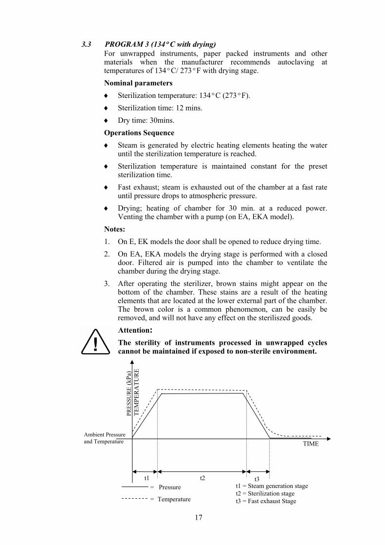
3.3 PROGRAM 3 (134ºC with drying) For unwrapped instruments, paper packed instruments and other
materials when the manufacturer recommends autoclaving at temperatures of 134ºC/ 273ºF with drying stage. Nominal parameters ♦ Sterilization temperature: 134ºC (273ºF). ♦ Sterilization time: 12 mins. ♦ Dry time: 30mins. Operations Sequence ♦ Steam is generated by electric heating elements heating the water
until the sterilization temperature is reached. ♦ Sterilization temperature is maintained constant for the preset
sterilization time. ♦ Fast exhaust; steam is exhausted out of the chamber at a fast rate
until pressure drops to atmospheric pressure. ♦ Drying; heating of chamber for 30 min. at a reduced power.
Venting the chamber with a pump (on EA, EKA model). Notes: 1. On E, EK models the door shall be opened to reduce drying time. 2. On EA, EKA models the drying stage is performed with a closed
door. Filtered air is pumped into the chamber to ventilate the chamber during the drying stage.
3. After operating the sterilizer, brown stains might appear on the bottom of the chamber. These stains are a result of the heating elements that are located at the lower external part of the chamber. The brown color is a common phenomenon, can be easily be removed, and will not have any effect on the steriliszed goods. Attention: The sterility of instruments processed in unwrapped cycles cannot be maintained if exposed to non-sterile environment.
TIME
PRES
SUR
E (k
Pa)
TEM
PER
ATU
RE
Ambient Pressure and Temperature
t1 t2 t3 t1 = Steam generation stage t2 = Sterilization stage t3 = Fast exhaust Stage
= Pressure
= Temperature
18
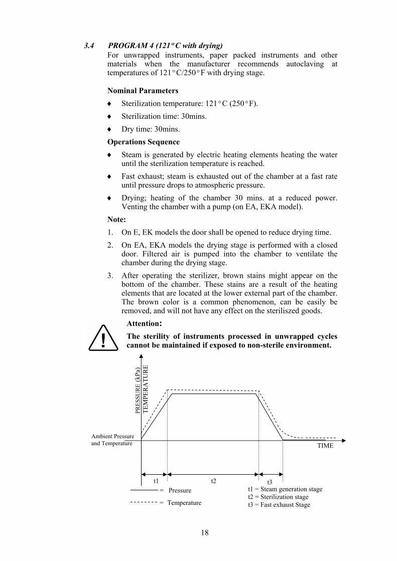
3.4 PROGRAM 4 (121ºC with drying) For unwrapped instruments, paper packed instruments and other
materials when the manufacturer recommends autoclaving at temperatures of 121ºC/250ºF with drying stage.
Nominal Parameters ♦ Sterilization temperature: 121ºC (250ºF). ♦ Sterilization time: 30mins. ♦ Dry time: 30mins. Operations Sequence ♦ Steam is generated by electric heating elements heating the water
until the sterilization temperature is reached. ♦ Fast exhaust; steam is exhausted out of the chamber at a fast rate
until pressure drops to atmospheric pressure. ♦ Drying; heating of the chamber 30 mins. at a reduced power.
Venting the chamber with a pump (on EA, EKA model). Note: 1. On E, EK models the door shall be opened to reduce drying time. 2. On EA, EKA models the drying stage is performed with a closed
door. Filtered air is pumped into the chamber to ventilate the chamber during the drying stage.
3. After operating the sterilizer, brown stains might appear on the bottom of the chamber. These stains are a result of the heating elements that are located at the lower external part of the chamber. The brown color is a common phenomenon, can be easily be removed, and will not have any effect on the steriliszed goods.
Attention: The sterility of instruments processed in unwrapped cycles cannot be maintained if exposed to non-sterile environment.
TIME
PRES
SUR
E (k
Pa)
TEM
PER
ATU
RE
Ambient Pressure and Temperature
t1 t2 t3 t1 = Steam generation stage t2 = Sterilization stage t3 = Fast exhaust Stage
= Pressure
= Temperature
19
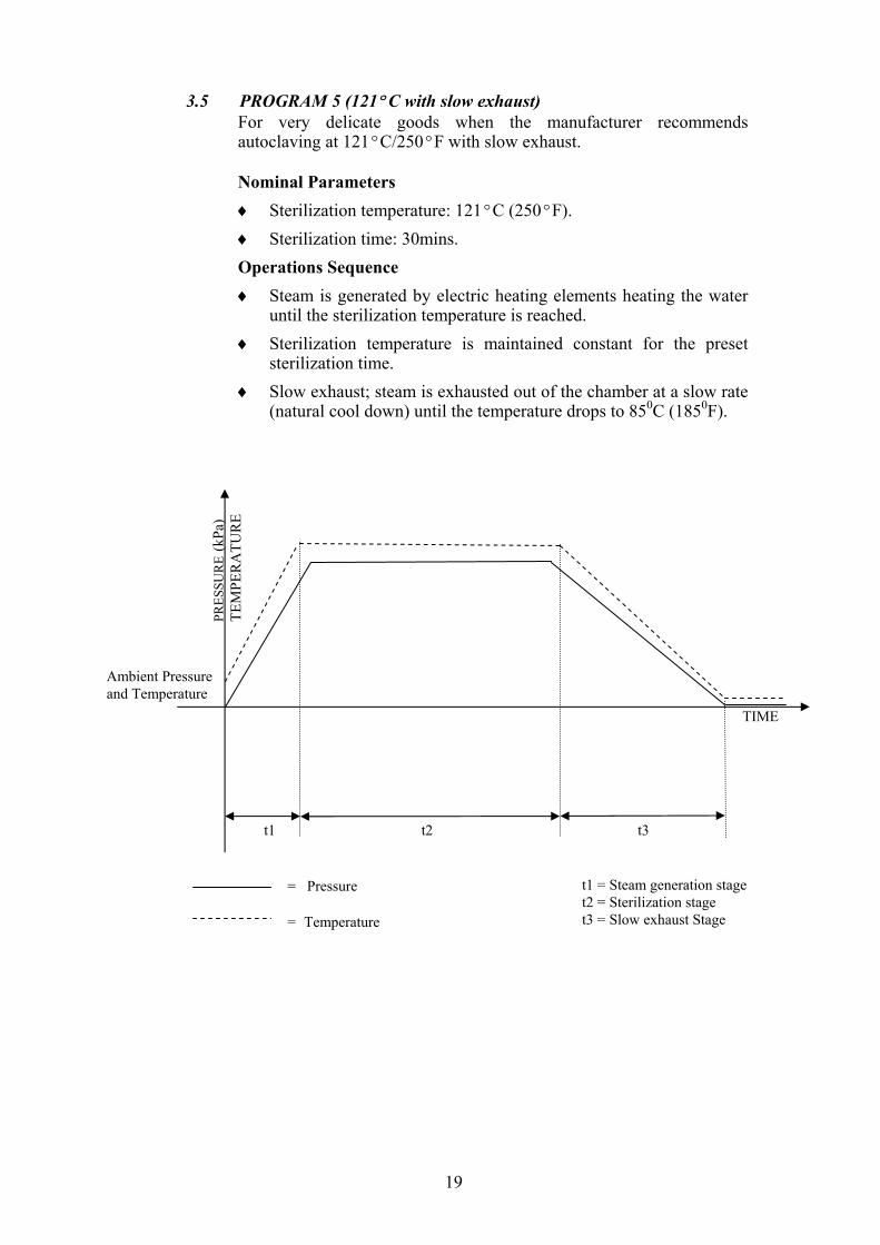
3.5 PROGRAM 5 (121ºC with slow exhaust) For very delicate goods when the manufacturer recommends
autoclaving at 121ºC/250ºF with slow exhaust.
Nominal Parameters ♦ Sterilization temperature: 121ºC (250ºF). ♦ Sterilization time: 30mins. Operations Sequence ♦ Steam is generated by electric heating elements heating the water
until the sterilization temperature is reached. ♦ Sterilization temperature is maintained constant for the preset
sterilization time. ♦ Slow exhaust; steam is exhausted out of the chamber at a slow rate
(natural cool down) until the temperature drops to 850C (1850F).
TIME
PRES
SUR
E (k
Pa)
TEM
PER
ATU
RE
Ambient Pressure and Temperature
t1 t2 t3
t1 = Steam generation stage t2 = Sterilization stage t3 = Slow exhaust Stage
= Pressure = Temperature
20
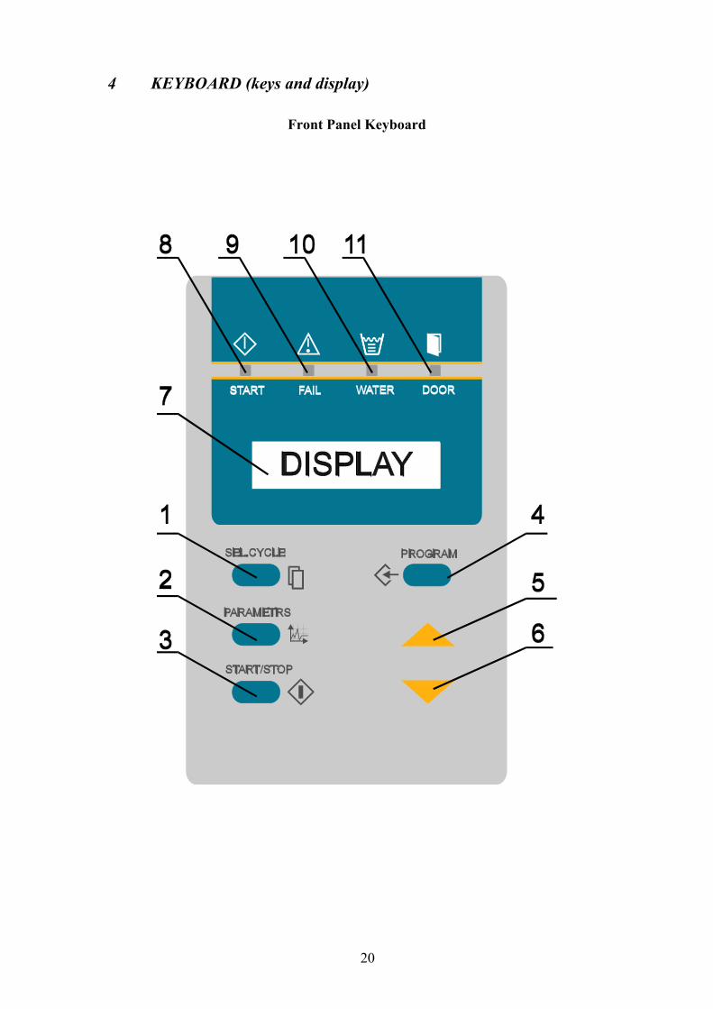
4 KEYBOARD (keys and display)
Front Panel Keyboard
21
4.1 Description and Functions of the Front Panel Keyboard
The command panel is comprised of 3 sections: On the lower section there are 6 keys; 3 command keys and 3
programming keys. The middle section consists of the LCD display with two rows and 16
characters on each line. The top section consists of 4 signal lights that indicate the status of the
autoclave.
1. Sel. Cycle (select cycle) key This key enables selecting the desired program out of 5 programs.
Pressing this key advances the selected program to the next program (e.g. from program 2 to 3).
If the system is set to program 5, pressing the key returns to program 1.
This autoclave has the following available programs: 1. Unwrapped instruments 134ºC (273ºF)/3min with fast
exhaust without drying. 2. Unwrapped instruments 121ºC (250ºF)/15min with fast
exhaust without drying. 3. Unwrapped and paper packed instruments, 134ºC
(273ºF)/12min. with 30min.and drying stage. 4. Unwrapped and paper packed instruments 121ºC
(250ºC)/30min. with 30min. and drying stage. 5. Very delicate goods 121ºC (250ºC)/30min. with slow
exhaust.
2. Parameters key This key displays for 3 seconds the three parameters of the
program. After selecting the program, it is possible to have the parameters displayed by pressing this key; the top line reads the following data:
Sterilization Temp Sterilization Time Dry Time 134ºC S = 3m. D=1Ø
The data is erased automatically after 3 seconds, or if the parameter key is pressed again during these three seconds.
3. Start/ Stop key This key commands the following 3 functions:
♦ Starting the process. ♦ Stopping the process. ♦ Canceling the FAIL message from the command panel and
opening the electric door locking. Note: “STOP” does not operate in EXH stage.
22
Starting the process: It is active while the autoclave is in standby position,
if the door is closed and water level in the reservoir is normal. Pressing this key starts the selected process.
Stopping the process: It is active while the autoclave is in process. Pressing
this key at any stage of the process stops operation. Canceling the FAIL message The end of an aborted process, the FAIL light is
turned on and an error message is displayed on the screen indicating the cause of the failure.
Pressing this key cancels the displayed message and switches off the FAIL light.
4. Program key This key is designed for programming the clock and setting
different parameters by the service technician by means of the UP (5) DOWN (6) keys.
When the PROGRAM key is pressed, the date is displayed with the cursor under the day. Pressing the PROGRAM key again moves the cursor under the month and then on to the year.
After pressing the PROGRAM key again the time of the day will be displayed with the cursor under the hour. Pressing the PROGRAM key again moves the cursor to the minutes parameter. Each time the UP/DN key is pressed, the value of the parameter above the cursor is changed.
After the date and time parameters are set, pressing the PROGRAM key shows CODE: 000.
A code known to the technical personnel will be set to change certain parameters and perform a digital calibration of the system, as described in detail in the technician manual.
5. UP key This key enables increasing the value displayed above the cursor,
at the clock programming and for setting of certain parameters by the technician.
6. DN key This key enables decreasing the value displayed above the cursor,
at the clock programming and for setting of certain parameters by the technician.
23
7. START LED indicator When the “START” LED indicator is on it; indicates that the
system is running a program.
8. FAIL LED indicator When the “FAIL” LED indicator is on; it indicates that the cycle
has failed either as a result of exceeding the allowable limits or the STOP key has been pressed.
9. WATER LED indicator When the “WATER” LED indicator is on; it indicates that there is
a lack of water in the reservoir.
10. DOOR LED indicator If the “Start” key is pressed and the door is unlocked the light will
signal twice and the buzzer will sound four times. If a cycle is in progress and fails on door unlocked “FAIL” LED
indicator will lit and a message “Door Unlock” will be displayed.
24
4.2 Description of the Operational Messages The display is comprised of 2 rows, each row has 16 characters.
4.2.1 The upper row: On the right side of the upper row, 6 characters are allotted
for displaying the stage in progress ♦ WATER − water inlet stage. ♦ HEAT − heating stage. ♦ STER − sterilization stage. ♦ EXH − exhaust stage ♦ DRY − dry stage
On the left side of the upper row, 10 characters are allotted for the selected programs. ♦ Fast 134 (FAST 273) − fast exhaust ♦ Fast 121 (FAST 250) − fast exhaust ♦ W.dry 134 (W.dry 273) − with drying stage. ♦ W.dry 121 (W.dry 250) − with drying stage. ♦ Slow 121 (Slow 250) − slow exhaust.
When the PARAMETERS key is pressed, the parameter of the selected program is displayed on the upper row.
4.2.2 The lower row: ♦ On the right side of the lower row, 5 characters are
allotted for chamber pressure display. ♦ The actual pressure is continuously displayed at all
stages of the process and between processes (standby). ♦ On the left side, of the lower row the temperature is
displayed; 5 characters are allotted for the display of temperature in ºC or ºF, in the form 134ºC or 273ºF.
♦ In case the process is aborted, the diagnosis of the fail is displayed on the left, of the lower row, instead of the temperature. 11 characters are allotted for this error message.
♦ On completion of the process, the END message is displayed in the interval between the readouts of temperature and pressure.
♦ At the sterilization and dry stage, the countdown of the time left to the completion of the stage will be displayed in the interval between the readouts of temperature and pressure. The format of the display will be MM: SS (two digits for minutes and two digits for seconds).
♦ The time between 2 complete cycles must be at least 10 minutes, in order to give the machine time to cool.
♦ When a cycle is started by means of pressing the START key, the load number is displayed for 2 seconds on the left of the lower row.
25
Examples Example 1: Autoclave between processes, the program No.1
has been selected.
Example 2: The autoclave in the sterilization stage, program
No.3 is running. Time left to completion is 3 minutes and 14 seconds.
Selected program W.dry Stage
Temperature Timer
Example 3: The process failed due to temperature drop in the sterilization stage in program No.2.
2 - FAST 121 EXH. LOW TEMP. 178K
3 - W DRY 134 STER 135ºC 03:14 318K
1 - Fast 134 ST.BY
35°C 100K
26
4.3 Description of Displayed Error Messages and Safety Measures Low Temp. Message is displayed, FAIL LED indicator lights and
cycle is aborted, if the temperature drops for more than 5 seconds below the sterilization temperature.
Low Heat Message is displayed and sterilization does not start if the autoclave has not reached sterilization temperature after heating for 30 minutes (except in slow exhaust program), and 60 minutes for the slow exhaust program.
High Temp. Message is displayed, FAIL indicator lights and the cycle is aborted in one of the following cases: ♦ If the temperature rises 3°C (6°F) above the
sterilization temperature during the sterilization stage.
♦ If the temperature sensor is damaged, this message appears during the HEAT stage.
Low Pres. Message is displayed, FAIL indicator lights, and the cycle is aborted if the pressure drops for more than 5 seconds below the pressure correlated to the sterilization temperature.
High Pres. This message is displayed, FAIL indicator lights, and the cycle is aborted if pressure rises above the pressure correlated to the sterilization temperature +3°C (6°F) for more than 5 seconds.
Temp Error Message is displayed and FAIL indicator lights if the temperature sensor PT100 is damaged or not calibrated.
Man. Stop Message is displayed and the FAIL indicator lights after the STOP key is pressed for longer than 1 second.
Power Dn Message is displayed if a power failure occurred during the STERILIZATION stage. When power resumes, the system automatically returns to the point of power failure. This message is displayed for several seconds and the printer prints POWER DN. If the temperature does not fall below the sterilization temperature, sterilization resumes automatically. When power returns, and if temperature falls below the sterilization temperature, the cycle will stop, exhaust will be performed according to the program requirements and the POWER DN and FAIL messages will be displayed and printed.
If a power failure occurred during Program 5 (slow 121), the system does not allow fast exhaust (as exhaust valve is normally closed) during a power failure or when power is back on.
If a power failure occurs during the HEAT stage, heating resumes (provided there is enough water in the chamber). If not, the cycle aborts. Dry and exhaust stages automatically resume operation once the power is back on.
27
Add Water Message is displayed and the “WATER” LED is lit in case of insufficient water in the water reservoir. After water is added to the reservoir, the START/STOP button must be pressed, to start the required sterilization cycle.
Door Unlock Message is displayed and the DOOR LED indicator
flashes if the door is improperly closed. The START button should be pressed to start the desired cycle. If the door accidentally opens during any stage of the cycle, the same message and indicator appears, and the system reacts as if the START/STOP key was pressed.
Low Water Message is displayed, FAIL indicator lights and the
program is aborted. ♦ If the electrode sensor indicates no water and the
safety thermostat cuts-off during the heating stage. ♦ If the thermostat is cut-off, and the micro-controller
presumes the electrode sensor is damaged.
28
5 PRINTER The printer is an optional device. If the autoclave is not equipped with a
printer paragraph 5 is not applicable. 5.1 Printer Operation The autoclave is equipped with a character printer, which prints a
detailed history of each cycle performed by the instrument (for the record or for subsequent consideration).
The printing is made on thermal paper with 24 characters per line and
contains the following information: ♦ Software version ♦ Real time ♦ Selected program ♦ Sterilization pressure ♦ Sterilization temperature ♦ Sterilization time ♦ Summary of performed cycle and identification hints.
When the sterilization cycle begins the printer starts printing the above
data. After the preliminary printing, the autoclave starts performing the
sequence of operations of the cycle. The measured values of temperature and pressure are printed at fixed time intervals, according to the phase of the process, as shown in the table below.
The data is printed from the bottom up, beginning with the program name and ending with “cycle ended” for a complete cycle or “FAIL” for an aborted cycle.
For an example of a typical printout, see next page.
29
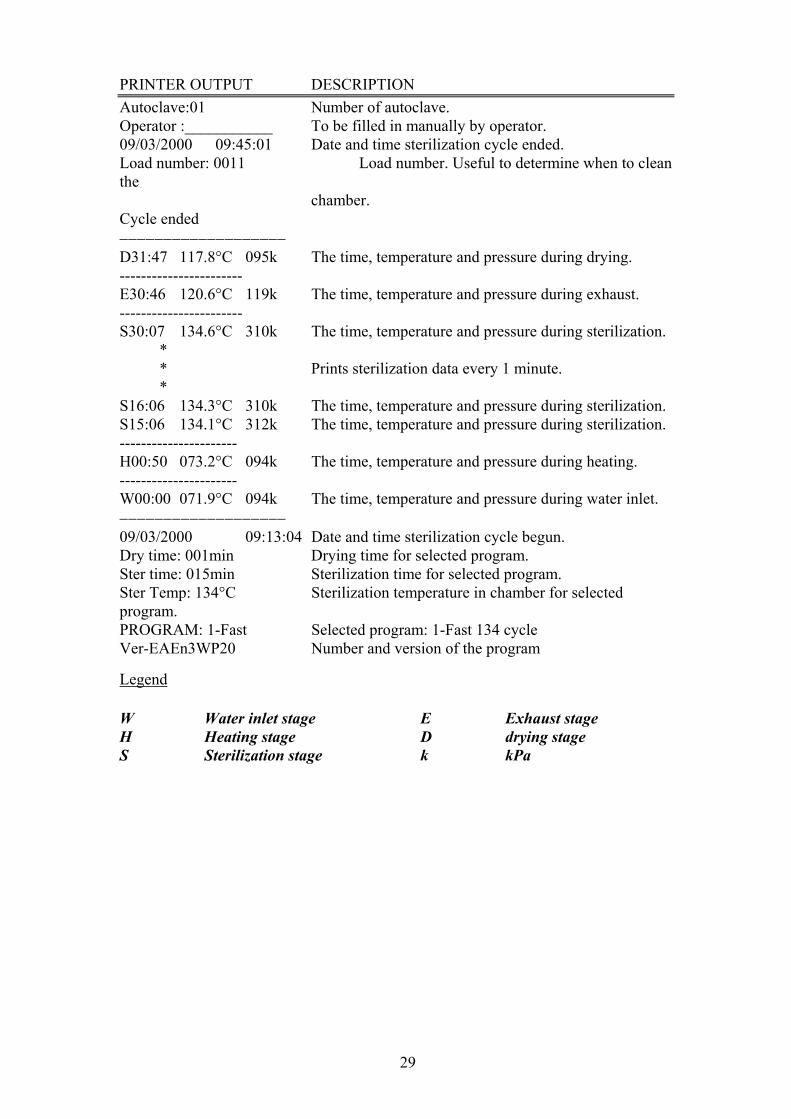
PRINTER OUTPUT DESCRIPTION Autoclave:01 Number of autoclave. Operator :___________ To be filled in manually by operator. 09/03/2000 09:45:01 Date and time sterilization cycle ended. Load number: 0011 Load number. Useful to determine when to clean the chamber. Cycle ended −−−−−−−−−−−−−−−−−−− D31:47 117.8°C 095k The time, temperature and pressure during drying. ----------------------- E30:46 120.6°C 119k The time, temperature and pressure during exhaust. ----------------------- S30:07 134.6°C 310k The time, temperature and pressure during sterilization. * * Prints sterilization data every 1 minute. * S16:06 134.3°C 310k The time, temperature and pressure during sterilization. S15:06 134.1°C 312k The time, temperature and pressure during sterilization. ---------------------- H00:50 073.2°C 094k The time, temperature and pressure during heating. ---------------------- W00:00 071.9°C 094k The time, temperature and pressure during water inlet. −−−−−−−−−−−−−−−−−−− 09/03/2000 09:13:04 Date and time sterilization cycle begun. Dry time: 001min Drying time for selected program. Ster time: 015min Sterilization time for selected program. Ster Temp: 134°C Sterilization temperature in chamber for selected program. PROGRAM: 1-Fast Selected program: 1-Fast 134 cycle Ver-EAEn3WP20 Number and version of the program Legend W Water inlet stage H Heating stage S Sterilization stage
E Exhaust stage D drying stage k kPa
30
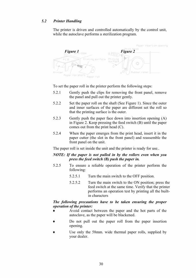
5.2 Printer Handling The printer is driven and controlled automatically by the control unit,
while the autoclave performs a sterilization program.
Figure 1 Figure 2
To set the paper roll in the printer perform the following steps: 5.2.1 Gently push the clips for removing the front panel, remove
the panel and pull out the printer gently. 5.2.2 Set the paper roll on the shaft (See Figure 1). Since the outer
and inner surfaces of the paper are different set the roll so that the printing surface is the outer.
5.2.3 Gently push the paper face down into insertion opening (A) in Figure 2. Keep pressing the feed switch (B) until the paper comes out from the print head (C).
5.2.4 When the paper emerges from the print head, insert it in the paper cutter (the slot in the front panel) and reassemble the front panel on the unit.
The paper roll is set inside the unit and the printer is ready for use.. NOTE: If the paper is not pulled in by the rollers even when you
press the feed switch (B) push the paper in. 5.2.5 To ensure a reliable operation of the printer perform the
following: 5.2.5.1 Turn the main switch to the OFF position. 5.2.5.2 Turn the main switch to the ON position; press the
feed switch at the same time. Verify that the printer performs an operation test by printing all the built-in characters
The following precautions have to be taken ensuring the proper operation of the printer: ♦ Avoid contact between the paper and the hot parts of the
autoclave, as the paper will be blackened. ♦ Do not pull out the paper roll from the paper insertion
opening. ♦ Use only the 58mm. wide thermal paper rolls, supplied by
your dealer.
31
6 INSTALLATION PLACING AND LEVELING INSTRUCTIONS Network
Network and connection should comply to the devices consumption. It must comply with local installation and safety rules and regulations. The voltage supplied to the device must comply with the label ± 5%. Caution:
The sterilizer must be placed on a rigid and leveled surface. The stand must be able to hold the load of the device and loaded material.
Note: Make sure while placing the autoclave, to leave space around the machine,
to give the technician access to service the machine. In order to avoid any injury by electrical hazard, it is mandatory for the
customer to have installed an earth leakage relay in the electrical board to which the autoclave is connected.
This relay disconnects all the poles of the electrical power line in case of accidental contact with the instrument metal enclosure, by the operator or another person, leading to a dangerous leakage current.
Note: Keep the back and the right side of the autoclave approximately 1” (25mm) away from the wall to allow for ventilation.
Connect the power cord to the socket on the rear side of the autoclave; plug it into the supply socket.
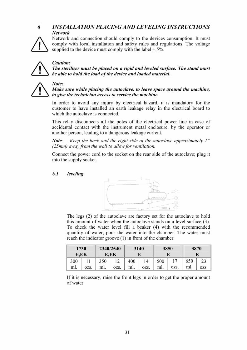
6.1 leveling
The legs (2) of the autoclave are factory set for the autoclave to hold this amount of water when the autoclave stands on a level surface (3). To check the water level fill a beaker (4) with the recommended quantity of water, pour the water into the chamber. The water must reach the indicator groove (1) in front of the chamber.
1730 E,EK
2340/2540 E,EK
3140 E
3850 E
3870 E
300 ml.
11 ozs.
350 ml.
12 ozs.
400 ml.
14 ozs.
500 ml.
17 ozs.
650 ml.
23 ozs.
If it is necessary, raise the front legs in order to get the proper amount
of water.
32
6.2 Water quantity for a cycle The amount of water in the autoclave chamber necessary for each
sterilization cycles as follows:
1730 E,EK
2340/2540 E,EK
3140 E
3850 E
3870 E
400 ml.
14 ozs.
550 ml.
19 ozs.
700 ml.
26 ozs.
1000 ml.
32 ozs.
1200 ml.
42 ozs.
It is imperative to have the correct amount of water for proper
operation of the autoclave! 6.3 Lifting and carrying
Caution: Before moving the autoclave, Make sure that the electric cord is disconnected from the power and there is no pressure in the chamber.
1. Disconnect the power supply cord. 2. Drain the water from the reservoir and vessel.
To avoid injuries, lifting and carrying should be done by two people. Do not drop this device!
6.4 Loading and unloading the Device
6.4.1 Safety Protective equipment and clothes and other safety
instructions should be implemented in accordance with local and national regulations and/or rules!
For proper sterilization - Do not overload the chamber. Only autoclavable products shall be used. Please refer to the manufacturer instructions for sterilization of unknown materials or instruments.
6.4.2 Loading Correct loading of the autoclave is essential to successful
sterilizing for several reasons. Efficient air removal from the chamber and the load will permit steam penetration and saturation, and allow proper drainage of condensate. Additionally, correct loading will reduce damage to packs and their contents and maximize efficient use of the sterilizer.
For detailed loading instructions, see para. 7 (Preparation before sterilization)
6.4.3 Unloading On completion of the cycle, the load shall be immediately
removed from the sterilizer and a visual inspection made to ascertain that the load is dry, and that sterilizing indicators have made the required colour change.
33
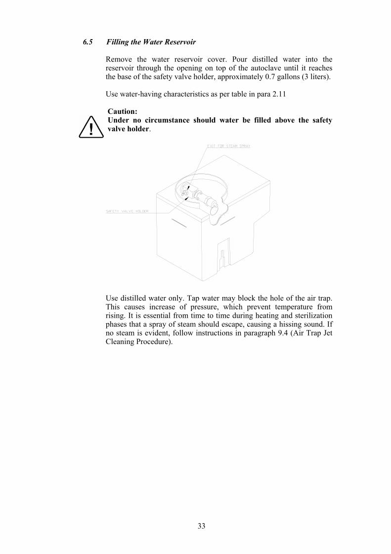
6.5 Filling the Water Reservoir Remove the water reservoir cover. Pour distilled water into the
reservoir through the opening on top of the autoclave until it reaches the base of the safety valve holder, approximately 0.7 gallons (3 liters).
Use water-having characteristics as per table in para 2.11
Caution: Under no circumstance should water be filled above the safety valve holder.
Use distilled water only. Tap water may block the hole of the air trap.
This causes increase of pressure, which prevent temperature from rising. It is essential from time to time during heating and sterilization phases that a spray of steam should escape, causing a hissing sound. If no steam is evident, follow instructions in paragraph 9.4 (Air Trap Jet Cleaning Procedure).
34
7 PREPARATION BEFORE STERILIZATION The purpose of packaging and wrapping of items for sterilization is to provide
an effective barrier against sources of potential contamination in order to maintain sterility and to permit aseptic removal of the contents of the pack. Packaging and wrapping materials should permit the removal of air from the pack, penetration of the sterilizing water vapor into the pack and removal of the sterilizing vapor.
The basic principle determining the size, mass and contents of instrument and hollowware packs is that the contents are sterile and dry immediately on completion of the drying cycle and removal of the pack from the sterilizer chamber.
Instruments to be sterilized must be clean, free from any residual matter, such as debris, blood, pads or any other material. Such substances may cause damage to the contents being sterilized and to the sterilizer. 1. Immediately after use, clean instruments thoroughly to dispose of any
residue. 2. It is recommended to wash instruments with an ultrasonic cleaner, using
detergent and mineral-free water. 3. Launder textile wraps prior to reuse. 4. After cleaning, rinse instruments for 30 seconds. (Follow manufacturer’s
instructions on the use of products for cleaning and lubricating instruments after using the ultrasonic cleaner).
5. Materials, including materials used for inner wraps, shall be compatible with the item being packed and the sterilizing method selected.
6. Do not place materials to be sterilized directly on the chamber’s wall. Place the material only on trays, rack, etc.
7. Before placing an instrument into the sterilizer tray, make sure that instruments which are not of the same metal, (stainless steel, carbon steel, etc.) are separated and placed on different trays.
Note: Check manufacturer’s instructions for the sterilization of each item.
8. In case carbon steel instruments are placed on stainless steel trays, the trays should be lined with a towel or paper wrap before placing the instruments on the trays. There should be no direct contact between the carbon steel and the stainless steel trays.
9. All instruments must be sterilized in an open position. 10. Use single-use wraps once only and discard after use.
35
11. Verify that the packaging method is in accordance with good practice approach and the packaging materials are in accordance with the applicable standards (e.g. EN868 series).
12. Place a sterilization indicator strip in each tray. 13. Place instruments with ratchets opened and unlocked or clipped on the
first ratchet position. 14. Disassemble or sufficiently loosen multiple-part instruments prior to
packaging to permit the sterilizing agent to come into contact with all parts of the instrument.
15. Tilt on edge items prone to entrap air and moisture, e.g. hollowware, so that only minimal resistance to air removal, the steam passage and condensate will be met.
16. Load items within the boundaries of the tray so that they do not touch the chamber walls, or fall off when the loading car is in transit.
17. The operator may use racks to allow for adequate separation of packaged instruments.
18. Load trays loosely to capacity. 19. Once a week, use a biological spore test indicator in any load to make
sure sterilization is performed. 20. Make sure that all instruments remain apart during the sterilization
cycle. 21. Empty canisters should be placed upside-down, in order to prevent
accumulation of water. 22. Allow a distance of approximately 2.5 cm (1”) between trays to permit
steam circulation. 23. Wrapped Instruments Wrapped instruments should be packed in material that promotes drying
such as autoclave bag, autoclave paper, and muslin towels. It is highly recommended to utilize the Tuttnauer Pouch Rack. This
rack allows the operator to place pouches on their side, thus increasing the capacity of the autoclave significantly and promoting better drying of the instruments. Contact your dealer for details.
Note: A table “Suitability of steam sterilization processes for various goods and method of packing” is added to the accompanying documents.
Pouch Rack
36
24. Packs 1. Place packs upright on trays, side by side. 2. Packs should not touch the chamber walls. 3. Pack instrument sets in a manner that prevents damage to delicate
items. 4. Pack hollowware sets so that all openings face the same direction
and so that the contents cannot move inside the pack. 5. Load packs of folded operating room drapes with layers vertical,
allowing air to be removed from the packs rapidly. 6. Do not place packs of hollowware and trays of instruments above
textile packs or soft goods in order to avoid wetting caused by condensation from items above.
7. Load items packed in flexible packaging materials on edge with paper to laminate, or flat with the paper surface downwards.
Note: The manufacturer’s recommendations shall be observed, concerning the sterilization data for each type of material.
25. Tubing When placing in a tray, make sure that both ends are open, without sharp
bends or twists.
Wrong
Right
37
26. Liquids Use only heat-proof glass, filled to 2/3 capacity. Ensure that the glass
container is covered, but not sealed to prevent pressure build-up.
Note: A table of suitability steam sterilization process for various goods and methods of packing is included with accompanying documents.
Liquids
38
8 OPERATING INSTRUCTIONS To avoid possible damage, do not leave the autoclave un-attended while in
operation It is important to clean the hole of the air jet, as described in para. 9.3
before starting operation of the autoclave, for the first time. 1. Remove the water reservoir cover. Pour distilled water into the reservoir
through the opening on top of the autoclave, until it reaches the base of the safety valve holder, approximately 0.7 gallons (3 liters).
2. Insert the plug into the electric socket. 3. Turn on the rocker switch mounted on the front panel to power control
circuits. 4. Set the clock for the proper date and time, by means of the PROGRAM
key (4), UP (5) and DOWN (6); see section 4. 5. Press the SELECT key (1) to select the required program. The name of
the program is displayed indicating the program that has been selected. 6. Press PARAMETERS key (2) to monitor the nominal parameters of the
program. 7. Load the material to be sterilized into the chamber according to
instructions in para. 7 (Preparation Before Sterilization), and close the door, until hand-tight.
The Door signal light is turned off indicating door is closed. Once the sterilization cycle is in progress, a safety device locks the door and makes it impossible to open it until completion of the cycle.
Note: Due to inherent elasticity of the door gasket, the Door indicator light
may be turned OFF before a complete seal is made between the door and the chamber.
Therefore, in order to ensure the door is fully sealed, when the Door light has been illuminated continue to tighten the door bolt until “hand-tight”.
Do not over - tighten the bolt as this may result in damage to the gasket.
Should the autoclave fail to reach the sterilizing temperature/pressure, always check if the door is fully sealed. If not, tighten the door bolt further, as described above, until completely sealed.
8. Press the START/ STOP key to put the autoclave in operation. The autoclave starts performing sequence of operations. The actual
measured values of pressure and temperature are displayed continuously and printed (if equipped with a printer) every minute at STE stage, and every 4 minutes at the other stages. The phase in progress is displayed at the right side of the upper line as WATER, HEAT, STER., EXH., and DRY.
If the operator presses the START key and the door is not completely closed, the process will not start and the DOOR light will flash twice then turn off and the buzzer will sound four times.
39
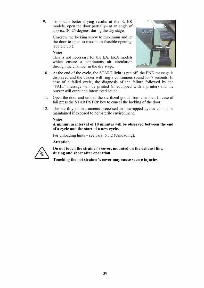
9. To obtain better drying results at the E, EK models, open the door partially– at an angle of approx. 20-25 degrees-during the dry stage.
Unscrew the locking screw to maximum and let the door to open to maximum feasible opening. (see picture).
Note: This is not necessary for the EA, EKA models
which ensure a continuous air circulation through the chamber in the dry stage.
10. At the end of the cycle, the START light is put off, the END message is displayed and the buzzer will ring a continuous sound for 7 seconds. In case of a failed cycle, the diagnosis of the failure followed by the “FAIL” message will be printed (if equipped with a printer) and the buzzer will output an interrupted sound.
11. Open the door and unload the sterilized goods from chamber. In case of fail press the START/STOP key to cancel the locking of the door.
12. The sterility of instruments processed in unwrapped cycles cannot be maintained if exposed to non-sterile environment.
Note: A minimum interval of 10 minutes will be observed between the end
of a cycle and the start of a new cycle. For unloading hints – see para. 6.3.2 (Unloading).
Attention Do not touch the strainer’s cover, mounted on the exhaust line, during and short after operation. Touching the hot strainer’s cover may cause severe injuries.
40
9 MAINTENANCE INSTRUCTIONS
9.1 Preventive and Scheduled Maintenance The maintenance operations described in this chapter have to be
fulfilled periodically to keep the device in good condition and to reduce the breakdown time to a minimum.
The user maintenance personnel, in accordance with further instructions can easily execute these operations.
The owner of the autoclave is responsible to call for an authorized technician to perform the periodical tests and preventive maintenance operations, as specified in the technician manual.
Use only mineral-free water as detailed in para. 2.11 (water quality).
9.1.1 Daily Clean door gasket with a soft cloth. The gasket should be
clean and smooth.
9.1.2 Weekly 1. Take out the tray holder and trays. Clean the tray
holder and trays with a cleaning agent & water and with a cloth sponge. You may use diluted lemon acid (25-50 CC lemon acid in 1 liter of water) as cleaning agent. If detergent is used, rinse the tray holder and trays immediately with water to avoid stains on then metal.
2. Once a week clean and descale the chamber, copper tubes and the reservoir using ‘Chamber Brite™’ (see para. 9.11).
Caution Do not use steel wool or steel brush as this can damage the chamber!
3. Put a few drops of oil on the 2 door pins and door tightening bolts.
4. Clean the outer parts of the autoclave with a soft cloth. 5. Once a week, or after 20 cycles (whichever comes
first), drain the water from the reservoir, and refill with fresh mineral-free water or distilled water (see para. 9.3).
6. Clean the electrode with a soft cloth. 7. Clean the air jet as per para. 9.4.
9.1.3 Periodically 1. Clean the strainer once a month as per para. 9.5.
Cleaning frequency may be reduced according to previous maintenance.
2. Once every month activate the safety valve (see para. 9.8).
3. Once every month, check the air trap jet. 4. On EA, EKA replace the air filter, every 6 months (see
para. 9.5).
41
5. Once every six months clean the fan grid with a vacuum cleaner from the inside outward.
6. Replace the door gasket every 12 months (see para. 9.4).
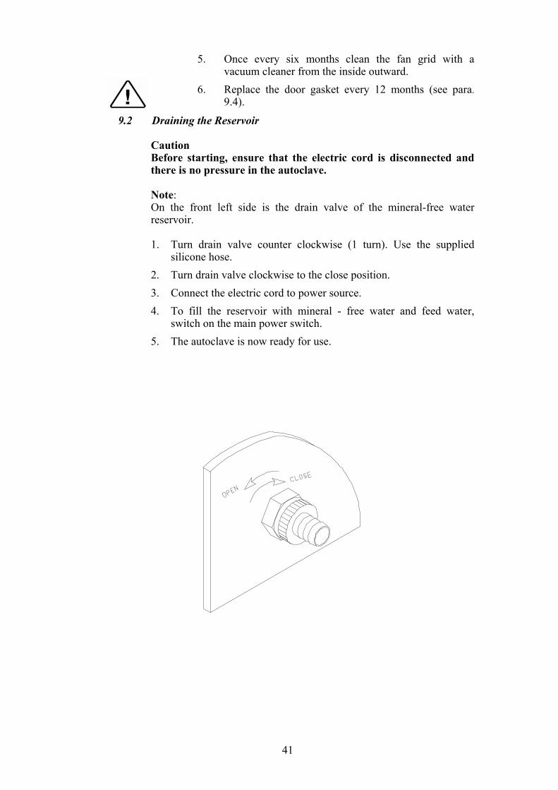
9.2 Draining the Reservoir Caution Before starting, ensure that the electric cord is disconnected and
there is no pressure in the autoclave. Note: On the front left side is the drain valve of the mineral-free water
reservoir.
1. Turn drain valve counter clockwise (1 turn). Use the supplied silicone hose.
2. Turn drain valve clockwise to the close position. 3. Connect the electric cord to power source. 4. To fill the reservoir with mineral - free water and feed water,
switch on the main power switch. 5. The autoclave is now ready for use.
42
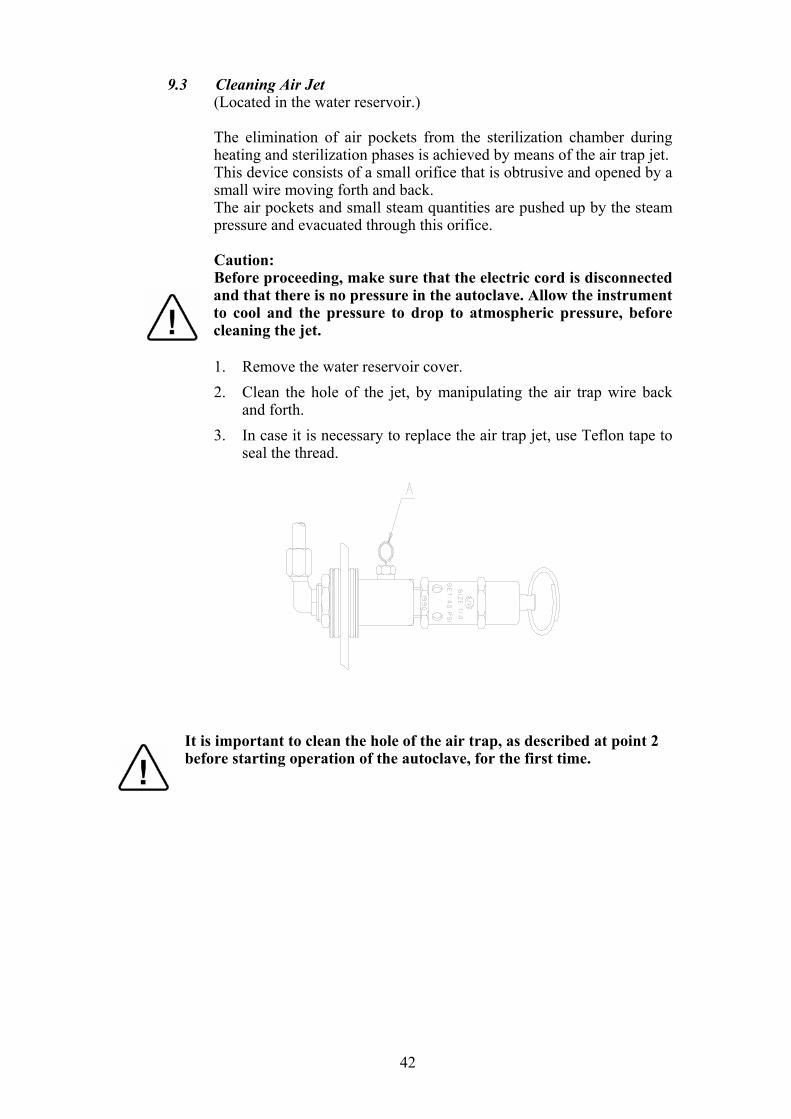
9.3 Cleaning Air Jet (Located in the water reservoir.) The elimination of air pockets from the sterilization chamber during
heating and sterilization phases is achieved by means of the air trap jet. This device consists of a small orifice that is obtrusive and opened by a
small wire moving forth and back. The air pockets and small steam quantities are pushed up by the steam
pressure and evacuated through this orifice. Caution: Before proceeding, make sure that the electric cord is disconnected
and that there is no pressure in the autoclave. Allow the instrument to cool and the pressure to drop to atmospheric pressure, before cleaning the jet. 1. Remove the water reservoir cover. 2. Clean the hole of the jet, by manipulating the air trap wire back
and forth. 3. In case it is necessary to replace the air trap jet, use Teflon tape to
seal the thread.
It is important to clean the hole of the air trap, as described at point 2 before starting operation of the autoclave, for the first time.
43
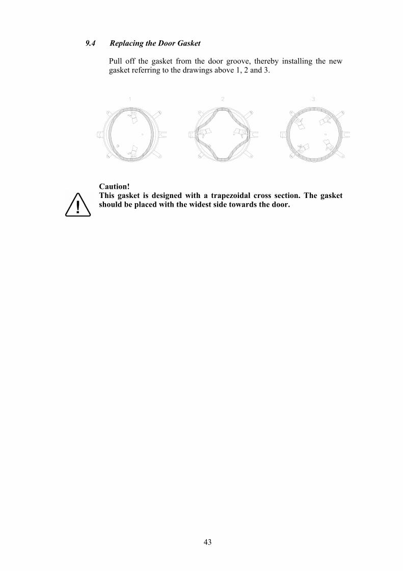
9.4 Replacing the Door Gasket Pull off the gasket from the door groove, thereby installing the new
gasket referring to the drawings above 1, 2 and 3.
Caution! This gasket is designed with a trapezoidal cross section. The gasket should be placed with the widest side towards the door.
44
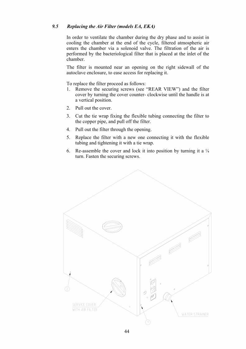
9.5 Replacing the Air Filter (models EA, EKA) In order to ventilate the chamber during the dry phase and to assist in
cooling the chamber at the end of the cycle, filtered atmospheric air enters the chamber via a solenoid valve. The filtration of the air is performed by the bacteriological filter that is placed at the inlet of the chamber.
The filter is mounted near an opening on the right sidewall of the autoclave enclosure, to ease access for replacing it.
To replace the filter proceed as follows:
1. Remove the securing screws (see “REAR VIEW”) and the filter cover by turning the cover counter- clockwise until the handle is at a vertical position.
2. Pull out the cover. 3. Cut the tie wrap fixing the flexible tubing connecting the filter to
the copper pipe, and pull off the filter. 4. Pull out the filter through the opening. 5. Replace the filter with a new one connecting it with the flexible
tubing and tightening it with a tie wrap. 6. Re-assemble the cover and lock it into position by turning it a ¼
turn. Fasten the securing screws.
45
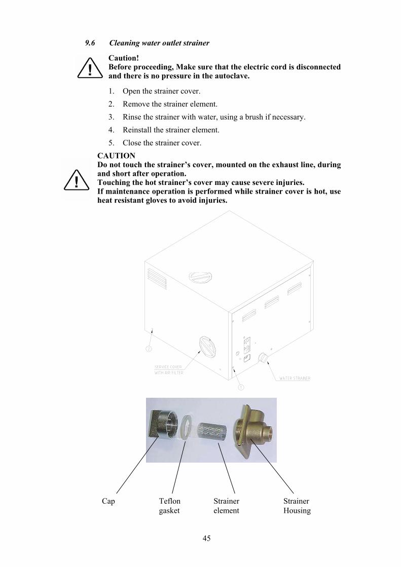
9.6 Cleaning water outlet strainer Caution! Before proceeding, Make sure that the electric cord is disconnected
and there is no pressure in the autoclave.
1. Open the strainer cover. 2. Remove the strainer element. 3. Rinse the strainer with water, using a brush if necessary. 4. Reinstall the strainer element. 5. Close the strainer cover.
CAUTION Do not touch the strainer’s cover, mounted on the exhaust line, during and short after operation. Touching the hot strainer’s cover may cause severe injuries. If maintenance operation is performed while strainer cover is hot, use heat resistant gloves to avoid injuries.
Cap Teflon gasket
Strainer element
Strainer Housing
46
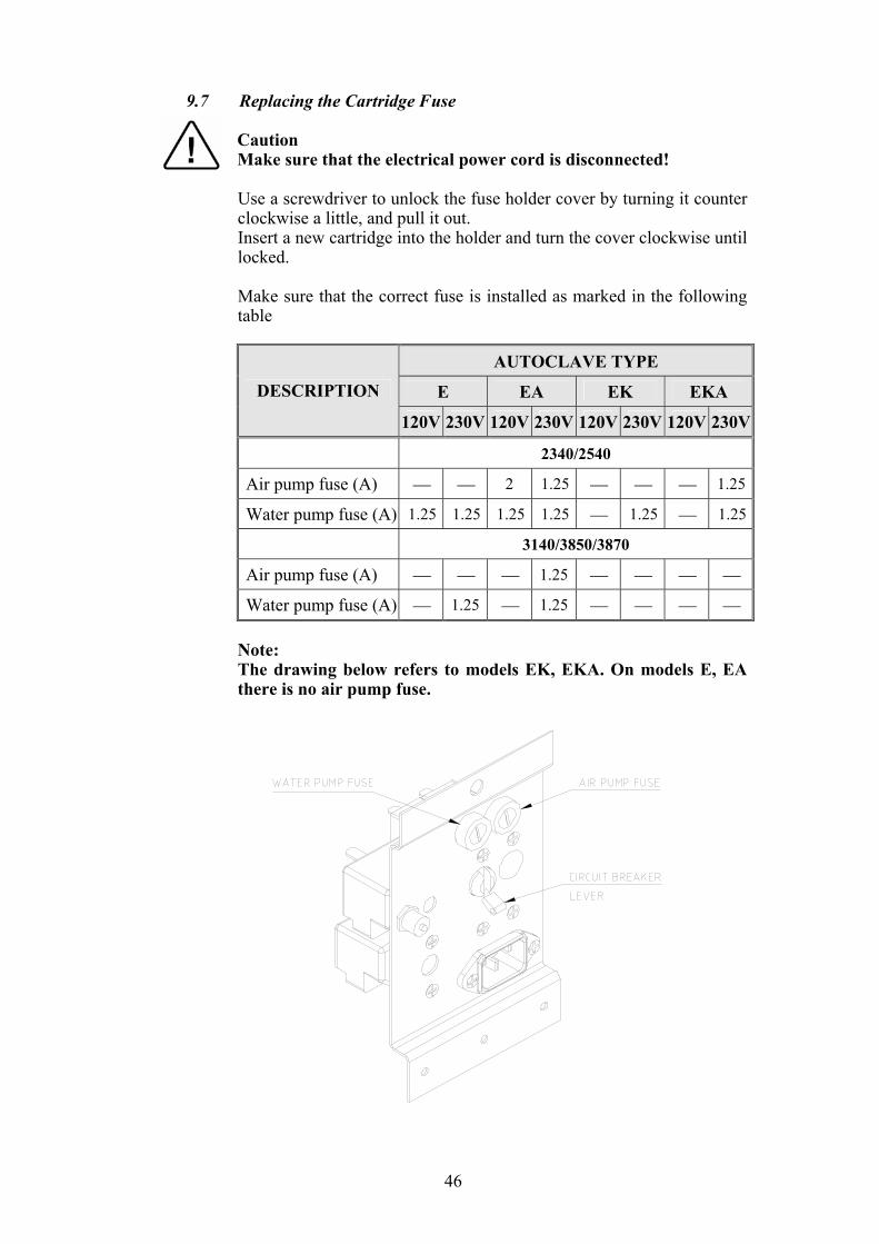
9.7 Replacing the Cartridge Fuse Caution Make sure that the electrical power cord is disconnected!
Use a screwdriver to unlock the fuse holder cover by turning it counter clockwise a little, and pull it out.
Insert a new cartridge into the holder and turn the cover clockwise until locked.
Make sure that the correct fuse is installed as marked in the following
table
AUTOCLAVE TYPE
E EA EK EKA DESCRIPTION
120V 230V 120V 230V 120V 230V 120V 230V
2340/2540
Air pump fuse (A) 2 1.25 1.25
Water pump fuse (A) 1.25 1.25 1.25 1.25 1.25 1.25
3140/3850/3870
Air pump fuse (A) 1.25
Water pump fuse (A) 1.25 1.25
Note: The drawing below refers to models EK, EKA. On models E, EA
there is no air pump fuse.
47
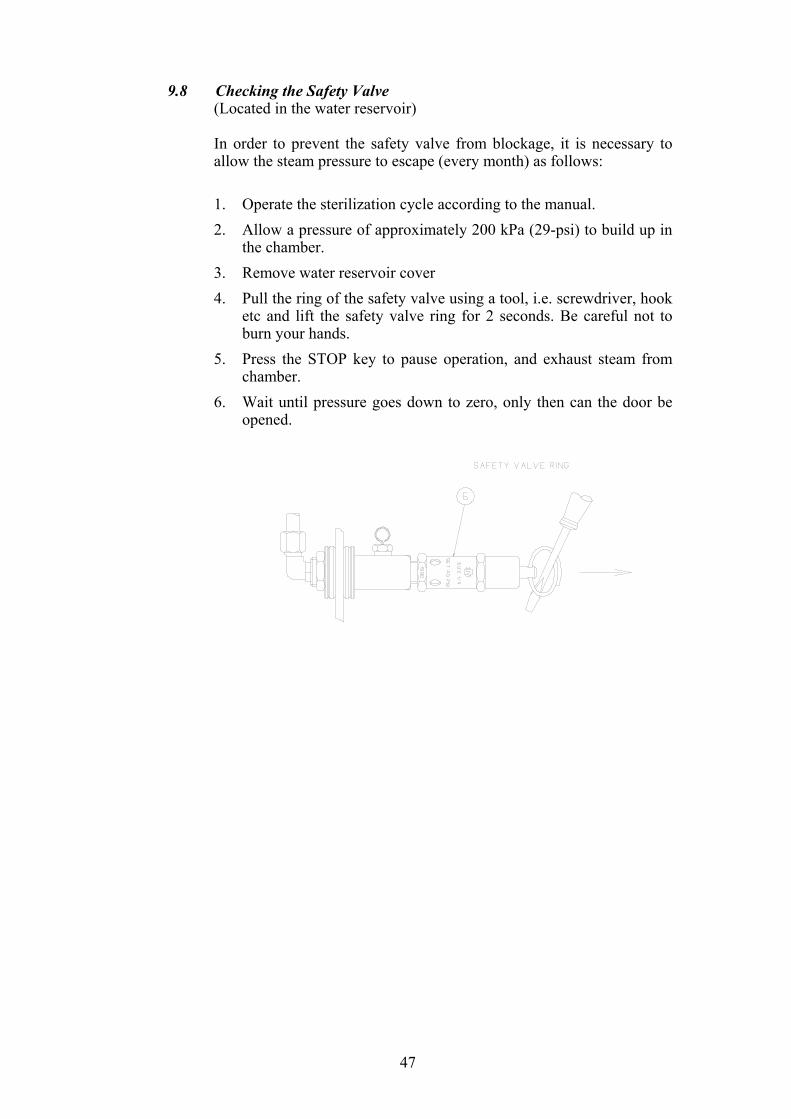
9.8 Checking the Safety Valve (Located in the water reservoir) In order to prevent the safety valve from blockage, it is necessary to
allow the steam pressure to escape (every month) as follows: 1. Operate the sterilization cycle according to the manual. 2. Allow a pressure of approximately 200 kPa (29-psi) to build up in
the chamber. 3. Remove water reservoir cover 4. Pull the ring of the safety valve using a tool, i.e. screwdriver, hook
etc and lift the safety valve ring for 2 seconds. Be careful not to burn your hands.
5. Press the STOP key to pause operation, and exhaust steam from chamber.
6. Wait until pressure goes down to zero, only then can the door be opened.
48
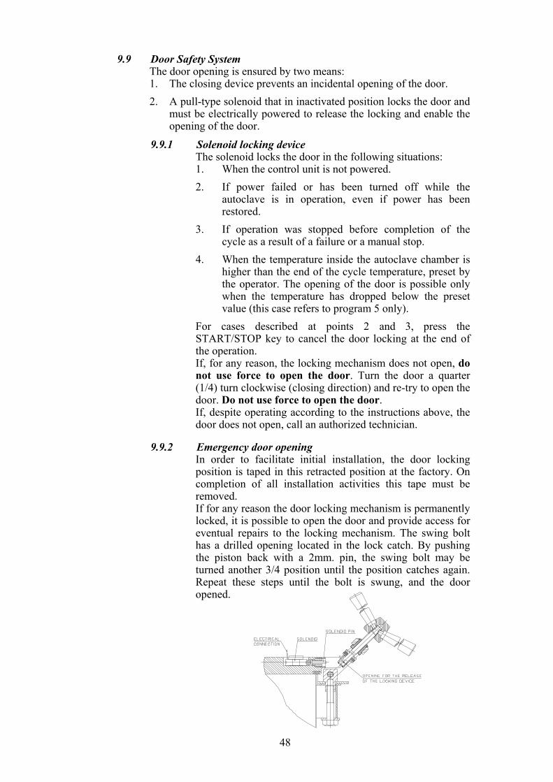
9.9 Door Safety System The door opening is ensured by two means:
1. The closing device prevents an incidental opening of the door. 2. A pull-type solenoid that in inactivated position locks the door and
must be electrically powered to release the locking and enable the opening of the door.
9.9.1 Solenoid locking device The solenoid locks the door in the following situations:
1. When the control unit is not powered. 2. If power failed or has been turned off while the
autoclave is in operation, even if power has been restored.
3. If operation was stopped before completion of the cycle as a result of a failure or a manual stop.
4. When the temperature inside the autoclave chamber is higher than the end of the cycle temperature, preset by the operator. The opening of the door is possible only when the temperature has dropped below the preset value (this case refers to program 5 only).
For cases described at points 2 and 3, press the START/STOP key to cancel the door locking at the end of the operation.
If, for any reason, the locking mechanism does not open, do not use force to open the door. Turn the door a quarter (1/4) turn clockwise (closing direction) and re-try to open the door. Do not use force to open the door.
If, despite operating according to the instructions above, the door does not open, call an authorized technician.
9.9.2 Emergency door opening In order to facilitate initial installation, the door locking
position is taped in this retracted position at the factory. On completion of all installation activities this tape must be removed.
If for any reason the door locking mechanism is permanently locked, it is possible to open the door and provide access for eventual repairs to the locking mechanism. The swing bolt has a drilled opening located in the lock catch. By pushing the piston back with a 2mm. pin, the swing bolt may be turned another 3/4 position until the position catches again. Repeat these steps until the bolt is swung, and the door opened.
49
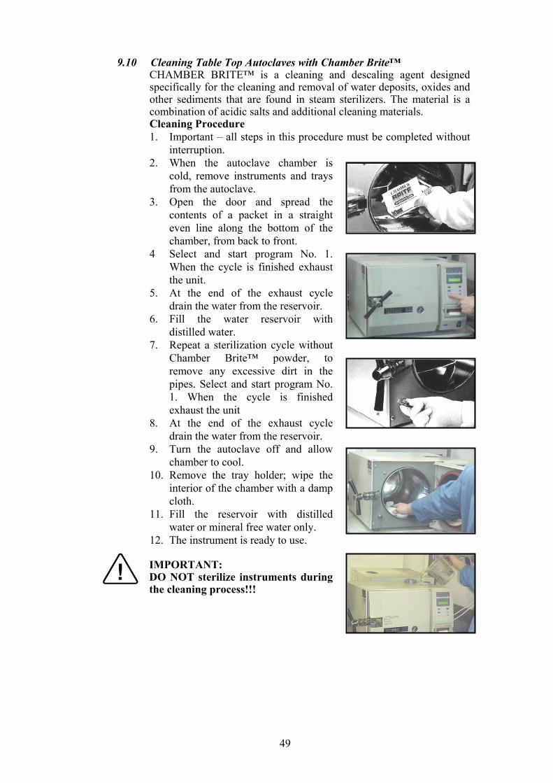
9.10 Cleaning Table Top Autoclaves with Chamber Brite™ CHAMBER BRITE™ is a cleaning and descaling agent designed
specifically for the cleaning and removal of water deposits, oxides and other sediments that are found in steam sterilizers. The material is a combination of acidic salts and additional cleaning materials.
Cleaning Procedure 1. Important – all steps in this procedure must be completed without
interruption. 2. When the autoclave chamber is
cold, remove instruments and trays from the autoclave.
3. Open the door and spread the contents of a packet in a straight even line along the bottom of the chamber, from back to front.
4 Select and start program No. 1. When the cycle is finished exhaust the unit.
5. At the end of the exhaust cycle drain the water from the reservoir.
6. Fill the water reservoir with distilled water.
7. Repeat a sterilization cycle without Chamber Brite™ powder, to remove any excessive dirt in the pipes. Select and start program No. 1. When the cycle is finished exhaust the unit
8. At the end of the exhaust cycle drain the water from the reservoir.
9. Turn the autoclave off and allow chamber to cool.
10. Remove the tray holder; wipe the interior of the chamber with a damp cloth.
11. Fill the reservoir with distilled water or mineral free water only.
12. The instrument is ready to use. IMPORTANT: DO NOT sterilize instruments during the cleaning process!!!
50
CAUTION: Keep out of reach of children. Contains mildly acidic ingredients. Avoid contact with the skin, eyes or clothing. Wash hands well after touching the powder, in the case of eye contact flush with continuous running water for at least 15 minutes. If irritation persists get medical attention. If accidentally swallowed, do not induce vomiting, drink large amounts of water and obtain medical attention. MSDS available upon request.
For models 1730, 2340, 2540 use one packet of CHAMBER BRITE™. For models 3140, 3850, 3870 use two packets of CHAMBER
BRITE™. Clean every 20 cycles or as needed.
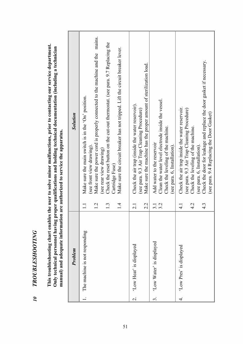
51
Solu
tion
1.1
Mak
e su
re th
e m
ain
switc
h is
in th
e ‘O
n’ p
ositi
on.
(s
ee fr
ont v
iew
dra
win
g).
1.2
Mak
e su
re th
e po
wer
cor
d is
pro
perly
con
nect
ed to
the
mac
hine
and
the
mai
ns.
(s
ee re
ar v
iew
dra
win
g)
1.3
Che
ck th
e re
set b
utto
n on
the
cut-o
ut th
erm
osta
t. (s
ee p
ara.
9.7
Rep
laci
ng th
e
Car
tridg
e Fu
se)
1.4
Mak
e su
re th
e ci
rcui
t bre
aker
has
not
trip
ped.
Lift
the
circ
uit b
reak
er le
ver.
2.1
Che
ck th
e ai
r tra
p (in
side
the
wat
er re
serv
oir)
.
(s
ee p
ara.
9.3
Air
Trap
Cle
anin
g Pr
oced
ure)
2.
2 M
ake
sure
the
mac
hine
has
the
prop
er a
mou
nt o
f ste
riliz
atio
n lo
ad.
3.1
Add
wat
er to
the
rese
rvoi
r 3.
2 C
lean
the
wat
er le
vel e
lect
rode
insi
de th
e ve
ssel
.
Che
ck th
e le
velin
g of
the
mac
hine
.
(s
ee p
ara.
6, I
nsta
llatio
n).
4.1
Che
ck th
e ai
r tra
p in
side
the
wat
er re
serv
oir.
(see
par
a. 9
.3 A
ir Tr
ap C
lean
ing
Proc
edur
e)
4.2
Che
ck th
e le
velin
g of
the
mac
hine
.
(s
ee p
ara.
6, I
nsta
llatio
n).
4.3
Che
ck th
e do
or fo
r lea
kage
and
repl
ace
the
door
gas
ket i
f nec
essa
ry.
(see
par
a. 9
.4 R
epla
cing
the
Doo
r Gas
ket)
10
TRO
UB
LESH
OO
TIN
G
T
his t
roub
lesh
ootin
g ch
art e
nabl
es th
e us
er to
solv
e m
inor
mal
func
tions
, pri
or to
con
tact
ing
our
serv
ice
depa
rtm
ent.
O
nly
tech
nica
l per
sonn
el h
avin
g pr
oper
qua
lific
atio
ns a
nd h
oldi
ng te
chni
cal d
ocum
enta
tion
(incl
udin
g a
tech
nici
an
m
anua
l) an
d ad
equa
te in
form
atio
n ar
e au
thor
ized
to se
rvic
e th
e ap
para
tus.
Prob
lem
1.
The
mac
hine
is n
ot re
spon
ding
2.
‘L
ow H
eat’
is d
ispl
ayed
3.
‘Low
Wat
er’ i
s dis
play
ed
4.
‘Low
Pre
s’ is
dis
play
ed
52
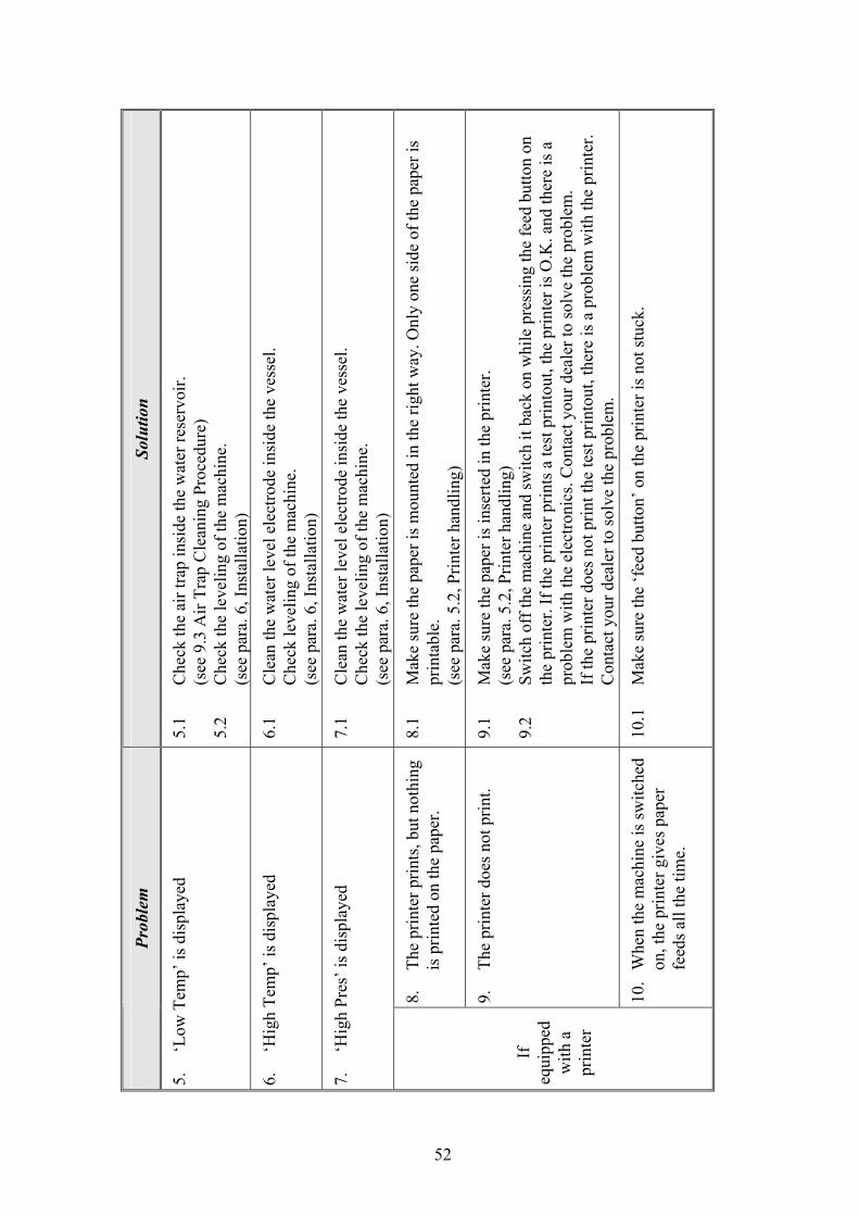
Solu
tion
5.1
Che
ck th
e ai
r tra
p in
side
the
wat
er re
serv
oir.
(see
9.3
Air
Trap
Cle
anin
g Pr
oced
ure)
5.
2 C
heck
the
leve
ling
of th
e m
achi
ne.
(s
ee p
ara.
6, I
nsta
llatio
n)
6.1
Cle
an th
e w
ater
leve
l ele
ctro
de in
side
the
vess
el.
C
heck
leve
ling
of th
e m
achi
ne.
(see
par
a. 6
, Ins
talla
tion)
7.1
Cle
an th
e w
ater
leve
l ele
ctro
de in
side
the
vess
el.
C
heck
the
leve
ling
of th
e m
achi
ne.
(s
ee p
ara.
6, I
nsta
llatio
n)
8.1
Mak
e su
re th
e pa
per i
s mou
nted
in th
e rig
ht w
ay. O
nly
one
side
of t
he p
aper
is
pr
inta
ble.
(see
par
a. 5
.2, P
rinte
r han
dlin
g)
9.1
Mak
e su
re th
e pa
per i
s ins
erte
d in
the
prin
ter.
(see
par
a. 5
.2, P
rinte
r han
dlin
g)
9.2
Switc
h of
f the
mac
hine
and
switc
h it
back
on
whi
le p
ress
ing
the
feed
but
ton
on
th
e pr
inte
r. If
the
prin
ter p
rints
a te
st p
rinto
ut, t
he p
rinte
r is O
.K. a
nd th
ere
is a
prob
lem
with
the
elec
troni
cs. C
onta
ct y
our d
eale
r to
solv
e th
e pr
oble
m.
If th
e pr
inte
r doe
s not
prin
t the
test
prin
tout
, the
re is
a p
robl
em w
ith th
e pr
inte
r.
Con
tact
you
r dea
ler t
o so
lve
the
prob
lem
.
10.1
M
ake
sure
the
‘fee
d bu
tton’
on
the
prin
ter i
s not
stuc
k.
8.
The
prin
ter p
rints
, but
not
hing
is
prin
ted
on th
e pa
per.
9.
The
prin
ter d
oes n
ot p
rint.
10.
Whe
n th
e m
achi
ne is
switc
hed
on, t
he p
rinte
r giv
es p
aper
fe
eds a
ll th
e tim
e.
Prob
lem
5.
‘Low
Tem
p’ is
dis
play
ed
6.
‘Hig
h Te
mp’
is d
ispl
ayed
7.
‘Hig
h Pr
es’ i
s dis
play
ed
If
equi
pped
w
ith a
pr
inte
r
53
Solu
tion
11.1
M
ake
sure
the
door
is ti
ghte
ned
enou
gh.
Rep
lace
the
door
gas
ket.
(see
par
a. 9
.4 R
epla
cing
the
Doo
r Gas
ket)
12.1
If
you
are
runn
ing
a ‘li
quid
s’ p
rogr
am th
is is
nor
mal
.
(see
, PR
OG
RA
M 5
)
13.1
C
lean
stra
iner
acc
ordi
ng to
inst
ruct
ions
.
Prob
lem
11.
The
mac
hine
is le
akin
g at
the
door
12.
Whe
n ru
nnin
g a
cycl
e, th
e ex
haus
t sta
ge ta
kes a
ver
y lo
ng
13.
Wat
er d
oes n
ot e
xit c
ham
ber d
ue
to c
logg
ed o
utle
t stra
iner
.
If th
e pr
oble
m p
ersi
sts,
cont
act y
our d
eale
r or p
oint
of p
urch
ase
for f
urth
er a
ssis
tanc
e.
54
POUCH RACK
Pouch Rack for models 2340, 2540
Pouch Rack for model 3870
CAT No. TYPE
2340 ACS215-0008
2540
ACS215-0010 3870
55
TRAY
TRAY HANDLE CMT240-0001 For 1730, 2340, 2450 models only
MODEL SIZE CAT. No.
1730 TRY173-0002
2340 TRY240-0001
2540 TRY240-0001
Big TRY314-0001 3140
Small TRY314-0002
Big TRY385-0003 3850
Small TRY385-0004
Big TRY387-0001 3870
Small TRY387-0003
56
TRAY HOLDER
ALTERNATIVE TRAY HOLDER
These tray holders are designed for use in models 2340 & 2540 only.
MODEL TRAY HOLDER CAT. NO.
1730 TRH173-0001
2340 TRH234-0001
2540 TRH254-0001
3140 TRH314-0000
3850 TRH385-0001
3870 TRH387-0001
57
11 ACSSESORIES LIST
Cat. No. Description
1730 2340 2540 3140 3850 3870
Tray Handle CMT240-0001 CMT240-0001 CMT240-0001 — — —
Pouch Rack — ACS215-0008 ACS215-0008 — — ACS215-0010
Big TRY314-0001 TRY385-0003 TRY387-0001Tray
Small TRY173-0002 TRY240-0001 TRY240-0001
TRY314-0002 TRY385-0004 TRY387-0003
Tray holder TRH173-0002 TRH234-0001 TRH254-0001 TRH314-0000 TRH385-0001 TRH387-0002
Alternative Tray Holder — TRH234-0008 TRH254-0009 — — —
Silicon drain tube GAS084-0007 GAS084-0007 GAS084-0007 GAS084-0007 GAS084-0007 GAS084-0007
Chamber Brite™ 1box (10 packets) CLE096-0026 CLE096-0026 CLE096-0026 CLE096-0026 CLE096-0026 CLE096-0026
12 SPARE PARTS LIST Cat. No.
Description 1730 2340 2540 3140 3850 3870
Water reservoir cover POL067-0004 POL067-0004 POL067-0004 POL067-0004 POL067-0004 POL067-0004
Door gasket GAS080-0021 GAS080-0002 GAS080-0003 GAS080-0029 GAS080-0004 GAS080-0004
Cord+plug+socket Europe-230V WIR040-0002 WIR040-0002 WIR040-0002 WIR040-0003 WIR040-0002 WIR040-0002
Cord +plug+ socket 115V (E, EA), USA WIR040-0004 WIR040-0004 WIR040-0004 — — —
Cord+plug+socket 230V (EK, EKA) USA — WIR040-0005 WIR040-0005 WIR040-0005 WIR040-0005 WIR040-0005
Cord +plug+ socket Australia, New-Zealand (E, EA)
WIR040-0006 WIR040-0006 WIR040-0006 WIR040-0006 — —
Strainer element SRV000-0235 SRV000-0235 SRV000-0235 SRV000-0235 SRV000-0235 SRV000-0235
Cap for¼” strainer FIL175-0027 FIL175-0027 FIL175-0027 FIL175-0027 FIL175-0027 FIL175-0027
Teflon gasket 3 mm GAS082-0007 GAS082-0007 GAS082-0007
Teflon gasket 4 mm GAS082-0008 GAS082-0008 GAS082-0008
Air filter (EA, EKA) FIL175-0010 FIL175-0010 FIL175-0010 FIL175-0010 FIL175-0010
Fuse 1.25 A ELE035-0005 ELE035-0005 ELE035-0005 ELE035-0005 ELE035-0005
Fuse 2 A (for EK, EKA) ELE035-0009 ELE035-0009 ELE035-0009 ELE035-0009 ELE035-0009