Embed Size (px)
Citation preview

RECKMANN
Reckmann Yacht Equipment GmbH • Siemensstraße 37-39 • D-25462 Rellingentel. +49/04101/38 49-0 • fax +49/04101/38 49 50
[email protected] • www.reckmann.com
EF 90
Betriebs- & WartungsanleitungOperation & Maintenance
Elektrische RollreffanlageElectric Furling Gear


Inhaltsverzeichnis / Index
Packliste / check list 1Produktbeschreibung / product description 3Tabelle mit Kürzungsmaßen / table of abridgements 4Bestimmung der Vorstaglänge D / forestay length D 4Bestimmung der Profillänge B / profile length B 4Profilmontagehinweise / profile assembly instructions 5
Ablängen des Profiles / shortening the foil top section 5Ablängen des Topschlauches / shortening the top hose 6Vorbereitung der Topkappe / preparation of the top cap 6Montage der Schläuche und Buchsen / assembly of the bushes and spacers 7Profilmontage / profile assembly 9
Segeleinführer und Fallenschlitten / halyard swivel and sail feeder assembly 11Montage des Elektroantriebes / installation of the gearbox 12
Verbindung von Profilen u. E-Antrieb / connection of profiles and the electric gear box 13Verbindung von Vorstag u. E-Antrieb / connection of the forestay and the electric gear box 14Montage der Vorstagspanners / reassembly of the adjuster 15
Montage der Schürze / assembly of the stainless steel cover 16Montieren der Topkappe / top cap installation 17Setzen der kompletten Rollreffanlage an Bord / installing the complete furling system on board 18Längeneinstellung des Vorstagspanners / length adjustment 19Schaltkasten/ electric control box 20Anschluß der Hauptkabel/ connecting the power cables 21Mastkopfkonstruktion / halyard leads 22Fallenschlittenposition / position of the halyard swivel 22Nothandbetrieb 23
emergency manual drive 24Ermittlung der Vorlieklänge / to find the right lufflength 25Technische Daten / technical data 26Betriebshinweise/ operating instructions 26Wartung / maintenance 26Technische Daten/ technical data sheet 28Händler und Service-Stationen/ distributors and service stations 29
Stand 15.06.2006

Packliste für EF 90 / Check list for EF 90
Kunde / customer: Datum / date:
Händler / distributor:
Auftragsnummer / order number:
Typ: EF 90 -.............. Vorstag: Draht mit ............ mm Durchmesser / Rod N .....
Type: EF 90 - ........... forestay: wire with ........... mm diameter / rod N .....
.......... .........m ungekürzte Profillänge „P“ Profiltyp R........... unshortened profiles „P“ type of profiles R...........
................... mm Vorstagforestay
... Klemmbacken N ...collets N ...
... Spezial Walzterminal mit GewindeSpecial swage terminal with thread
... Topterminal: ... Sta-lok ... Walzterminal ... AugterminalTopterminal: ... Sta-lok ... swage terminal ... eye terminal
1 Elektroantrieb mit Toggle und 2,5m Anschlußkabelelectric furler with toggle and 2.5m electric wire
1 Windenkurbelwinchhandle
1 Fallenschlittenhalyard swivel
2 Schnappschäkel für Antrieb und Fallenschlittensnap shackle for furler and halyard swivel
1 Untere Profilsektion 3000 mm / 5980 mmlower profile section 3000 mm / 5980 mm
... Standard Profilsektion 3000 mm / 5980 mmstandard profile section 3000 mm / 5980 mm
... Standard Profilsektion 1500 mmstandard profile section 1500 mm
... Topsektion .................... mmTop section .................... mm
1 Untere Gewindeplatte mit Schrauben ( an der unteren Profilsektion montiert )Bottom thread plate with screws ( assembled on the lower profile section )
1 Segeleinführersail feeder
... Profilverbinder 2-teiligsplit join connectors
Seite / page 1

Profile R20, R30 und R40 Profile R50profiles R20,R30 and R40 profiles R50
... Schlauch 200 mm ... Distanzrohr 240 mmhose 200 mm spacer tubes 240 mm
... Schlauch 340 mm ... Distanzrohr 1660 mmhose 340 mm spacer tubes 1660 mm
... Schlauch 500 mm ( rot markiert ) ... Verbinderbuchse mit zwei Schraubenhose 500 mm ( marked red ) splice bearing with two screws
... Schlauch 600 mm ... Verstärkungsbuchsehose 600 mm bearing reinforcement
... Schlauch ................... mm ... untere Profilverstärkunghose ............................ mm lower reinforcement
... Delrinbuchsen ( 2 Reserve )delrin bearings ( 2 spare part )
... VA Einlegekeil für Profilverbinder ( 1 Reserve)stainless steel insert for split join connectors ( 1 spare part )
... Schraube für Profilverbinder ( 2 Reserve )screw for split join connectors (2 spare part )
1 Fußbuchse ( 2-teilig )bottom bearing ( 2 pieces )
1 Topkappe mit Schrauben ( 2-teilig )top cap with screws (2 pieces )
1 E-Schaltkastenelectric control box
1 Drucktasterpush buttons
1 Anschlußboxconnecting box
2 Decksdurchführungen für Kabelthrough deck fittings for wire
1 Montageanleitungowner´s manual
1 Werkzeug: 1 Hakenschlüssel, 3 Innensechskantschl. (SW3/4/6), Stiftschraube M6tools: 1 hook key, 3 socket wrenches (size 3/4/6), hexagon socket set screw M6
Sonderzubehör:additional equipment:
Zusammengestellt:Packed by:
Seite / page 2
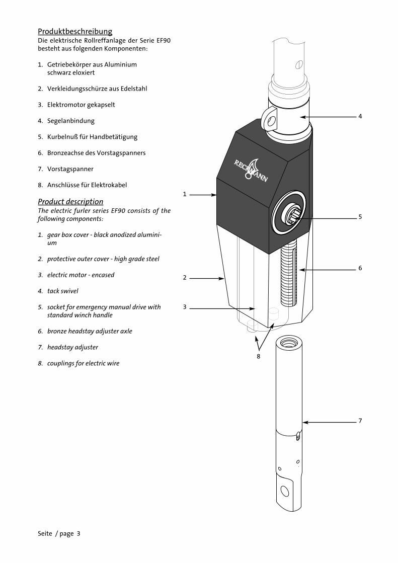
ProduktbeschreibungDie elektrische Rollreffanlage der Serie EF90besteht aus folgenden Komponenten:
1. Getriebekörper aus Aluminium schwarz eloxiert
2. Verkleidungsschürze aus Edelstahl
3. Elektromotor gekapselt
4. Segelanbindung
5. Kurbelnuß für Handbetätigung
6. Bronzeachse des Vorstagspanners
7. Vorstagspanner
8. Anschlüsse für Elektrokabel
Product descriptionThe electric furler series EF90 consists of thefollowing components:
1. gear box cover - black anodized alumini-um
2. protective outer cover - high grade steel
3. electric motor - encased
4. tack swivel
5. socket for emergency manual drive with standard winch handle
6. bronze headstay adjuster axle
7. headstay adjuster
8. couplings for electric wire
4
5
6
7
1
2
3
8
Seite / page 3

Tabelle mit KürzungsmaßenTable of abridgements
T = ......... mm
F = ......... mm
Vorstaglänge DForestay length D
D = A - E - T
D = ........ - ........ - ........
D = ........
Profillänge BProfile length B
B = D - F - G - H
B = ...... - ...... - ...... - ......
B = ........
F
H
B
G
D
E
T
A
Seite / page 4
Verstellung inMittelpositionadjuster inmid position
E Gmm mm
Draht / wire 300 247Rod 308 237Draht / wire 367 283Rod 377 273
EF90-2
EF90-3
S2.5 ab S3H 90 mm 100 mm

Ablängen des ProfilsUm das Kürzungsmaß C zu erhalten, setzen Siedas Maß P ( ungekürzte Profillänge, sieheSeite 1 ) und das Maß B in die vorbereiteteRechnung ein. Kürzen Sie nun eines der 3000mm langen Standardprofile um das Kürzungs-maß C .Diese Sektion ist jetzt die Topsektion.
Shortening the foil top sectionTo obtain the measurement C make an entry, inthe prepared calculation below, of measure-ments P ( the total length of sections supplied,see page 1) and B ( your total required foil sec-tion lengths ) . Shorten one of the 3000 mmstandard sections by the length C. This will nowbe the top section.
P = .........
B = .........
C = P - B
C = ......... - ......... = .........( P ) ( B ) ( C )
TopprofilTop section3000 mm
C
B
P
Seite / page 5

Seite / page 6
Ablängen desTopschlauchesSchneiden Sie das Maß C von dem Top-schlauch ab.
Shortening of the top hoseA long spacer tube is provided for the top sec-tion and this will have to be cut to suit. Cut thedimension C also from this spacer tube.
1740
mm
C
15mm
d
TopprofilTop section
Vorbereitung der TopkappeStecken Sie die beiden Hälften der Topkappeso in das Topprofil, daß die Trennungsebeneder beiden Hälften von der Vorderkante desProfils zur Hinterkante mit den Nuten ver-läuft.Bohren Sie nun zusammen, wie auf der Abbil-dung zu sehen, auf beiden Seiten durch dasProfil und die jeweilige Topkappenhälfte einLoch mit dem Durchmesser d (siehe Tab. un-ten ). Für die weitere Montage entfernen Siedie Topkappe wieder.
Preparation of the top capInsert both halfes of the top cap into the topsection and carefully drill a pilot hole ( tablefor d below ) on each side for the screws pro-vided. Remove the top cap for installation lat-er.
Typ/type d R 20 3,0 mmR 30 4,0 mmR 40 4,0 mm

Seite / page 7
rot
red
rot
red
rot
red
rot
red
rot
red
rot
red
Ro
d
600
600
Lo
we
r se
ctio
n
600
500
340
.....
x S
tan
dar
d s
ect
ion
150
0
600
600
500
600
600
.....
x S
tan
dar
d s
ect
ion
300
0
600
1740
- C
To
p s
ect
ion
Ro
d
500
600
200
200
200
Dra
ht
/ wir
e
Dra
ht
/ wir
e
Ro
dv
ors
tag
: D
as
Au
ffä
de
ln d
er
Bu
chse
n u
nd
Sch
läu
che
erf
olg
t vo
r d
em
Pre
sse
n d
es
Ro
d -
Kop
fes
un
d n
ach
Mon
tage
des
Au
gter
min
als
von
un
ten
üb
er d
as S
tag.
Ers
t w
erd
en d
ie 7
Top
bu
ch-
sen
un
d d
anac
h d
ie S
chlä
uch
e u
nd
Bu
chse
n d
erTo
pse
ctio
n a
ufg
esch
oben
. Jet
zt f
olge
n d
ie B
uch
sen
un
d S
chlä
uch
e d
er
Sta
nd
ard
Se
ctio
ne
n 3
00
0,
gem
äß ih
rer
An
zah
l. Fa
lls e
ine
1500
mm
Sta
nd
ard
Sect
ion
au
fgru
nd
der
bes
tell
ten
Pro
fill
än
ge
inIh
rem
Lie
feru
mfa
ng
en
tha
lten
ist
, m
üss
en d
ieen
tsp
rech
end
en S
chlä
uch
e d
iese
r Se
ctio
n (
sieh
eA
bb
.) d
an
ach
fo
lgen
. A
bsc
hli
eßen
d w
erd
en d
ieS
chlä
uch
e u
nd
Bu
chse
n d
er
Low
er
Se
ctio
nau
fges
chob
en.
Prü
fen
Sie
, ob
zu
den
4 a
bge
bild
e-te
n B
uch
sen
am
un
tere
n E
nd
e d
es S
tag
es z
usä
t-zl
ich
e, g
emäß
der
Tab
elle
, not
wen
dig
sin
d. F
alls
ja,
sch
ieb
en S
ie d
iese
zu
sam
men
mit
den
4 a
bge
bild
e-te
n B
uch
sen
au
f.
Dra
htv
ors
tag
:D
as
Au
ffä
del
n d
er B
uch
sen
un
dSc
hlä
uch
e er
folg
t vo
m T
op
des
Sta
ges
au
s, v
or
Mo
nta
ge
des
To
pte
rmin
als.
Zu
erst
wer
den
die
4a
bg
eb
ild
ete
n B
uch
sen
, a
m u
nte
ren
En
de
de
sSt
ages
au
fges
chob
en.
Wen
n z
usä
tzlic
he
Bu
chse
n,
gem
äß d
er n
eben
steh
end
en T
abel
le n
otw
end
igsi
nd
, sc
hie
ben
Sie
d
iese
als
näc
hst
es a
uf.
Wie
in
der
Ab
bild
un
g ge
zeig
t, f
olge
n j
etzt
die
Sch
läu
che
un
d B
uch
sen
der
Lo
wer
Sec
tio
n.
Fall
s ei
ne
15
00
mm
Sta
nd
ard
Sec
tion
au
fgru
nd
der
bes
tellt
en P
ro-
fill
än
ge
in
Ih
rem
Lie
feru
mfa
ng
en
tha
lte
n i
st,
mü
ssen
die
en
tsp
rech
end
en S
chlä
uch
e d
iese
r Se
c-ti
on (s
ieh
e A
bb
.) d
anac
h f
olge
n. A
nsc
hlie
ßen
d w
er-
den
die
Sch
läu
che
un
d B
uch
sen
der
Sta
nd
ard
Sec
-ti
on
30
00
mm
, w
ie g
ezei
gt,
au
fges
cho
ben
. A
b-
sch
ließ
end
wer
den
in
bei
den
Fäl
len
die
Sch
läu
che
un
d B
uch
sen
der
Top
Sec
tion
au
fges
chob
en.
Rod
/Dra
ht:
Ver
mei
den
Sie
gro
ße
Zwis
chen
räu
me
un
d s
chie
ben
Sie
die
Bu
chse
n u
nd
Sch
läu
che,
wie
in d
er A
bb
ildu
ng
geze
igt,
zu
sam
men
. G
estr
ich
elt
ange
deu
tet
ist
die
Pos
itio
n d
er s
pät
er e
inge
bau
ten
Mon
tage
der
Sch
läu
che
un
d B
uch
sen
nac
h A
blä
ng e
n d
es V
orst
ages
Top
un
d F
uß
bu
chse
. Fü
r d
ie r
eib
un
gslo
se M
onta
ged
er P
rofi
le i
st u
nb
edin
gt a
uf
die
ric
hti
ge R
eih
en-
folg
e d
er v
ersc
hie
den
en S
chlä
uch
e u
nd
Bu
chse
n z
uac
hte
n!!
Die
500 m
m S
chlä
uch
e s
ind
an d
en E
nd
en
rot
mark
iert
.
The
500
mm
spa
cer
tube
s ar
e m
arke
d re
d at
eac
hen
d.
Top
sch
lau
ch /
top
spac
er
Zusä
tzlic
he
Bu
chse
nEx
tra
bu
shes
R20
2
R30
kein
e /
no
R40
kein
e /
no

Seite / page 8
Wir
e fo
rest
ay:
Aft
er f
itti
ng
the
low
er t
erm
inal
an
dbe
fore
ass
embl
y of
th
e to
p te
rmin
al, t
he
bush
es a
nd
spac
er t
ube
s ar
e fi
tted
fro
m t
he
top
to t
he
bott
omas
sh
own
in
th
e di
agra
m a
bove
. Fi
t th
e 4
bot
tom
bu
shes
fir
st t
og
eth
er w
ith
an
y a
dd
itio
na
l b
ush
esth
at m
ay b
e re
quir
ed a
s sh
own
in t
he
tabl
e ab
ove
(se
e pa
ge 9
top
lef
t ).
It i
s im
port
ant
that
th
e or
der
and
nu
mbe
rs o
f bu
shes
an
d sp
acer
tu
bes
are
fitt
edas
sh
own
in
th
e di
agra
m. T
his
will
en
sure
th
at t
he
500
mm
spa
cers
, wh
ich
are
mar
ked
red,
will
be
cor-
rect
ly p
osi
tio
ned
fo
r ea
ch f
oil
sec
tio
n j
oin
. W
ith
som
e sy
stem
s, d
epen
din
g o
n t
he
tota
l se
ctio
nle
ngt
hs
supp
lied,
th
ere
may
be
a 15
00 m
m lo
ng
sec-
tion
of
foil.
Th
e bu
sh a
nd
tube
spa
cin
gs f
or t
his
par
-ti
cula
r se
ctio
n a
re f
itte
d t
o t
he
low
er e
nd
of
the
stay
, as
illu
stra
ted,
en
suri
ng
that
it is
sit
uat
ed o
n f
i-n
al a
ssem
bly
imm
edia
tely
abo
ve t
he
feed
er (
bot
-to
m )
sec
tio
n.
Fin
ally
aft
er f
itti
ng
all
bu
shes
an
dsp
ace
r tu
bes
in
th
e co
rrec
t se
qu
ence
, fi
t th
e to
psp
acer
an
d 7
bu
shes
to
the
top
end.
Bef
ore
fitt
ing
the
top
term
inal
, en
sure
th
at a
l t
he
bush
spa
cin
gs
are
corr
ect
and
will
mat
ch t
he
foil
join
posi
tion
s.
Rod
/ w
ire:
To
ensu
re a
ccu
rate
con
stru
ctio
n w
hen
fitt
ing
the
foil
sect
ion
s, c
hec
k th
at t
her
e ar
e n
o ga
psbe
twee
n t
he
bush
es a
nd
spac
er t
ube
s. O
utl
ined
in
the
diag
ram
abo
ve is
th
e to
p ca
p an
d bo
ttom
bea
r-in
g f
or
inst
all
ati
on
aft
er f
itti
ng
th
e fo
ils.
Th
ese
item
s en
sure
th
at t
he
bush
es a
nd
spac
er t
ube
s re
-m
ain
cap
tive
wit
hin
th
e fo
il se
ctio
ns.
Montage des TopterminalsDen Vorstagdraht so einkürzen, dass zwis-chen den Terminals das Maß D erreicht wird.Oberes Augterminal nach der Beschreibungdes Herstellers montieren.
Cutting the wire headstayCut the headstay wire according to size D .Mount the eye terminal at the top accordingto the manufacturer's instructions.
Ass
embl
y of
th
e bu
shes
an
d sp
acer
tu
bes
afte
r sh
orte
nin
g th
e fo
rest
ay
Ro
d f
ore
sta
y: A
fter
ass
emb
ly o
f th
e ey
e te
rmin
al
and
befo
re c
old
hea
din
g th
e ro
d, s
lide
the
bush
esan
d sp
acer
tu
bes
onto
th
e fo
rest
ay f
rom
th
e bo
ttom
to t
he
top
as s
how
n in
th
e di
agra
m a
bove
. Fit
th
e 7
top
bush
es f
irst
an
d th
en t
he
top
spac
er w
hic
h w
ascu
t to
mat
ch t
he
top
sect
ion
. It
is
impo
rtan
t th
atth
e or
der
and
nu
mbe
rs o
f bu
shes
an
d sp
acer
tu
bes
are
fitt
ed a
s sh
own
in t
he
diag
ram
. Th
is w
ill e
nsu
reth
at
the
50
0 m
m s
pa
cers
, w
hic
h a
re m
ark
ed r
ed,
will
be
corr
ectl
y po
siti
oned
for
eac
h f
oil s
ecti
on jo
in.
Wit
h s
ome
syst
ems,
dep
endi
ng
on t
he
tota
l sec
tion
len
gth
s su
pplie
d, t
her
e m
ay b
e a
1500
mm
lon
g se
c-ti
on o
f fo
il. T
he
bush
an
d tu
be s
paci
ngs
for
th
is p
ar-
ticu
lar
sect
ion
are
fit
ted
to
th
e lo
wer
en
d o
f th
est
ay, a
s ill
ust
rate
d, e
nsu
rin
g th
at it
is s
itu
ated
on
fi-
nal
ass
embl
y im
med
iate
ly a
bove
th
e fe
eder
( b
ot-
tom
) se
ctio
n. F
inal
ly, a
fter
fit
tin
g al
l th
e bu
shes
an
dsp
acer
tu
bes
in t
he
corr
ect
sequ
ence
, fit
th
e 4
bush
esto
th
e lo
wer
en
d.
Wit
h s
om
e sy
stem
s a
dd
itio
na
lbu
shes
will
be
requ
ired
as
show
n in
th
e ta
ble
abov
e(
see
page
9 t
op l
eft
). B
efor
e h
eadi
ng
the
rod,
en
-su
re t
hat
all
the
bush
spa
cin
gs a
re c
orre
ct a
nd
will
mat
ch t
he
foil
join
pos
itio
ns.

1
2
ProfilmontageNach dem Aufschieben der Schläuche undBuchsen auf das Stag und dem Kürzen desTopprofiles beginnt die Profilmontage.
Reihenfolge der Profilsektionen :Top Section -- ...... x Standard Section 3000 --...... x Standard Section 1500 -- Lower Section
Ziehen Sie das Topprofil von unten bis zumTop und legen Sie zwei Profilverbinder anden rot markierten Schlauch ( Fig.1 ).Legen Sie dann die Gewindeplatte (1) in diedafür vorgesehene Aussparung ein und acht-en Sie auf Deckungsgleichheit der Platten-und Verbinderlöcher , schieben Sie an-schließend die gesamte Verbindung (2) zurHälfte in das Topprofil ( Fig.2 ).
Seite / page 9
Profile assemblyAfter the assembling of the bushes and hoseson the forestay and the shortening of the topprofile start to assemble the profiles.
Sequence of the profiles:Top section -- ...... x Standard section 3000 --...... x Standard section 1500 -- Lower section
From the bottom end of the stay, slide on andfeed the top profile along to the top end of thestay. When in place, assemble a pair of splitjoin sleeves over the stay at the spacer tube,marked red, directly under the top section ( fig.1 ). Insert a stainless steel plate ( 1 ) into the re-cess on the top half of the join sleeve andmake sure that the holes of the plate and thejoin sleeve are on the same side.Push the join sleeve half of its length into theupper foil section (2). ( fig. 2 ).
Fig.1 Fig.2
rot/red

Profilmontage ( Forts. )Sichern Sie den Profilverbinder im Profil mitzwei Tuff-lock Schrauben ( Fig.3 ). Danach leg-en Sie die zweite Gewindeplatte ein .Schieben Sie jetzt das zweite Profil über denProfilverbinder ( Fig.4 ). Sichern Sie das zweiteProfil ebenso wie das erste mit zwei Tuff-lockSchrauben ( Fig.5 ). Ziehen Sie die Schraubenerst dann richtig an, wenn alle 4 einwandfreigefaßt haben.
Profile assembly ( cont. )Secure the join sleeve with 2 tuff-lock screws( fig. 3 ). Slide the next piece of extrusionfrom the bottom end over the stay up to thejoin sleeve. Insert the lower stainless steelplate into the recess in the join sleeve (fig. 3).Slide the foil section over the join sleeve(fig.4) until it butts cleanly with the uppersection and then secure it with 2 tuff-lockscrews (fig.5). This process is repeated untilall the foil sections are in place.
Fig.3 Fig.4 Fig.5
Seite / page 10

Seite / page 11
Montage von Segeleinführer und Fall-enschlitten Typ I für die Profile R20,R30 und R40Schieben Sie den Fallenschlitten von untensoweit auf das Profil, daß er oberhalb derAussparung für den Segeleinführer sitzt.Achten Sie bitte hierbei auf die richtige Ein-baulage des Fallenschlittens, wie in der Abbil-dung dargestellt. Falls der Segeleinführerschon am Profil montiert sein sollte, muß erdemontiert werden bevor der Fallenschlittenaufgeschoben wird. Setzen Sie zur Montageden Einführer in die Aussparung im Profil.Schieben Sie nun von hinten die Klammerüber das Profil und sichern sie die Verbindungmit zwei Schrauben.
Halyard swivel type I and sail feederassembly for profiles R20, R30 andR40.Slide the halyard swivel over the stay and foilsection along into a position above the sailfeeder. Check that the swivel travels smoothlyover the foil and that it is the correct way up.In case that the sail feeder is already placed, ithas to be removed first. Then re-place the sailfeeder into position in the recess on the lowerfoil section and secure with the providedclamp and screws. Please note! For the follow-ing installations the swivel has to to placedabove the sail feeder.

Montage des Elektroantriebes Zur einfacheren Montage legen Sie das Elek-trogetriebe neben das untere Ende desVorstages. Demontieren Sie zuerst die Edelstahl-Verklei-dung durch lösen der 4 Befestigungsmuttern.Um den Vorstagspanner von dem Getriebeabzuschrauben, müssen die beiden Paßfed-ern (2) entfernt werden. Schrauben Sie hierzudie vorher entfernten Schrauben (1) in diejeweils unteren Löcher der Paßfedern, dieFedern werden so aus ihrem Sitz gepreßt.Schrauben Sie dann den Spanner (3) aus dem
Installation of the gear box For easy installation of the gear box, lay it be-side the bottom end of the forestay sections.First remove the 4 stainless steel cover lockingnuts and slide the cover down.To remove the adjuster take the two keys (2)apart. Therefore use the two locking screws (1)unscrewed before. Screw the two screws (1) inthe lower thread holes of the keys, by this op-eration the key will be pushed out.At least unsecure the adjuster(3) and safe allthe parts until the reassembly.
2x
2x
(1)
(2)
(3)
Seite / page 12
Flansch heraus und legen alle Teile zurspäteren Montage zur Seite.

Seite / page 13
Verbindung von Profilen und Elek-troantriebStecken Sie die zweiteilige Fußbuchse (1) indas untere Profil, setzen Sie danach dieGewindeplatte (2) in die Aussparung undführen dann das Getriebe auf die zuvor amunteren Ende eingefetteten Profile in denProfilmitnehmer. Sichern Sie anschließenddie Profile mit den zwei zugehörigen In-nensechskantschrauben (3) in dem Profilmit-nehmer.
Connection of sections and the electricgear boxInsert the split bottom bearing (1) into thelower foil section, then insert the bottomthread plate (2) into its recess, then push theforestay together with the lower foil section,greased at its bottom end, into the profileadapter. Secure the foil and the adapter withtwo cap screws (3) provided.
1
2
3
1

Seite / page 14
Verbindung von Vorstag und AntriebRod: Ziehen Sie das Vorstag so weit aus demFlansch heraus, daß Sie die beiden Klemm-backen auf das Stag setzen können. NachdemSie die Klemmbacken auf dem Kopf desStages positioniert haben, werden die beidenHälften mit der Schraube verbunden undzusammen mit dem Stag in den Flanschzurückgeschoben bis die Klemmbacken voll-ständig in ihrer Aufnahme im Flansch sitzen.Connection of the forestay and thegear boxRod: Slide the forestay out of the flunge as faras it will go. ( It may be necessary to push therod quite firmly from the top end ). Fit the splitretaining brackets around the rod head and fixboth halfes with the screw provided. Aftergreasing push them firmly back into their seatinside the flunge.
Draht: Ziehen Sie das Vorstag so weit ausdem Flansch heraus, daß Sie die Spezialmut-ter auf das Terminal schrauben können.Nachdem Sie die Mutter ganz auf das Termi-nal geschraubt haben, sichern Sie diese mitdem zugehörigen Stift. Anschließend ziehenSie das Vorstag so weit in den Flansch zurück,daß die Mutter vollständig in ihrer Aufnahmesitzt.
Wire: Slide the forestay out of the flunge as faras it will go. ( It may be necessary to push thewire quite firmly from the top end ). Screw onthe special nut and secure with the pin provid-ed. Pull the headstay from the top as far aspossible to ensure that the bottom end is seat-ed correctly into its seat inside the flunge.

Montage des VorstagspannersSchrauben Sie den Vorstagspanner (3) in denFlansch bis die Paßfedernuten deckungsgle-ich sind. Setzen Sie dann die beiden Paßfed-ern (2) in die Nuten und sichern diese an-schließend mit den beiden Schrauben (1).Der Antrieb ist jetzt mit dem Stag verbunden.
Reassembly of the adjusterScrew the adjuster (3) into the flunge until thekey ways are non overlapping. Insert the twokeys (2) and secure them with the two screws(1) provided.
2x
2x
(1)
(2)
(3)
Seite / page 15

Reassembly of ss-coverMount the stainless steel cover in reversed or-der as discribed on page 12.
Montage der SchürzeMontieren Sie jetzt wieder die Edelstahlschürzein der umgekehrten Reihenfolge wie auf Seite12 beschrieben.
Seite / page 16

Seite / page 17
Montieren derTopkappeSchieben Sie die Topkappe in das Profil undverschrauben Sie diese dann mit den beidenSchrauben.Achtung : Über der Topkappe darf keine Del-rinbuchse mehr zu sehen sein.
Top cap installationEnsure that all the delrin bushes are inside thefoil section and then insert the top cap into thetop profile and secure in place with the twoscrews provided.

Seite / page 18
Setzen der kompletten RollreffanlageFür das Aufbringen der Anlage bitten wir, fol-gende Hinweise zu beachten: Die Durchbiegung des Alu-Profiles soll so ger-ing wie möglich gehalten werden. Durch einestarke Abknickung können die Profilebeschädigt werden.Sie können das Aufbringen des Vorstages aufzwei Arten durchführen. Wir empfehlengerne, sofern genug Helfer vorhanden sind,das Aufbringen des Vorstages nach dem Set-zen des Mastes, wie in Fig.1 dargestellt,vorzunehmen .Beachten Sie hierbei, daß die Anlage keines-falls am Fallenschlitten hochgezogen werdendarf. Stattdessen knoten Sie ein Fall unter-halb des Topterminals um das Vorstag undziehen die Anlage daran zum Masttop hoch.Beim Setzen des Mastes mit angeschlagenerRollreff-Anlage sind eher Beschädigungenvon Mast und Rollreff-System möglich.Wenn Sie den Mast zusammen mit der Roll-reff-Anlage, wie in Fig.2 dargestellt, setzen, sobitten wir, darauf zu achten, daß dasVorstagsende am Mastkopf nicht abgeknicktwird.
Installing the complete furling systemThe following points should be noted when in-stalling the Reckmann-Furler :Avoid damage to the profiles on installationthrough excessive bending.The headstay unit can be installed in two ways:either fitted to a stepped mast as in fig.1 orwith the mast as it is stepped as in fig. 2. If thesecond way is chosen, avoid bending the head-stay at the masthead, particularly if the halyardsheave protrudes beyond the headstay pin.
Fig.1
Fig.2

Length adjustmentAfter connecting the furler to the deck chain-plate, rotate the adjuster (2) with the providedhook tool to obtain the required forestaylength and tension. First wihdraw the securityscrew (1) and the key (2). To push out the keyuse the M6 thread pin provided and screw it inthe hole of the key.The maximum furler length is reached, whenthe mark "STOP" on the adjuster is visible tothe front of the outer cover. Remember to se-cure the adjuster with the key (2) and the capscrew (1) after making any adjustments.
LängeneinstellungWenn Sie die Sicherungsschraube (1) derPaßfeder entfernt haben, können Sie diePaßfeder (2), die die Spanner gegen unbeab-sichtigtes verstellen sichert, ebenfalls entfer-nen. Um die Paßfeder herauszudrückenschrauben Sie den mitgelieferten M6Gewindestift in die PaßfederAnschließend können Sie die Länge der An-lage durch Drehen der Verstellhülse (3) än-dern, benutzen Sie bitte dazu den mit-gelieferten Hakenschlüssel. Die Maximal-länge der Anlage ist erreicht, wenn beim Her-ausdrehen die Markierung "STOP" die Edel-stahlschürze erreicht hat. Abschließend sich-ern Sie die Verstellhülse wieder mit der zuge-hörigen Paßfeder (2) und Schraube (1).
Seite / page 19
VerstellwegAdjuster range
STOP STOP

Seite / page 20
-
S2
S1
S4S3
SchaltkastenDer Schaltkasten sollte gut zugänglich in derNähe des Cockpits montiert werden um denÜberlastschalter einfach erreichen zu können.Zum Anschluß der Kabel beachten Sie bitteden Schaltplan auf der übernächsten Seite.
Für den Anschluß an die Batterie und dieVerbindung zwischen Anschlußkasten undSchaltkasten empfehlen die folgenden Kabel-querschnitte. Der Kabelquerschnitt ist ab-hängig von der Länge. Maßgebend ist diedoppelte Länge zwischen Verbraucher undBatterie. 24V
bis 10m Länge => Querschnitt 35mm2
bis 20m Länge => Querschnitt 50mm2
bis 30m Länge => Querschnitt 70mm2
12V
bis 10m Länge => Querschnitt 70mm2
bis 20m Länge => Querschnitt 95mm2
bis 30m Länge => Querschnitt 150mm2
Electric control boxThe controlbox should be placed close to thecockpit. For wirering notice the wirering diagram onthe next page.For the connection of akkumulator and con-necting box we recommend the following ca-ble sizes. The size of the cable depends on thedistance between akkumulator and furler. Therequired length is twice the distance betweenakkumulator and furler.24V
up to 10m length => size 35mm2
up to 20m length => size 50mm2
up to 30m length => size 70mm2
12V
up to 10m length => size 70mm2
up to 20m length => size 95mm2
up to 30m length => size 150mm2
Schaltkasten 12V / control box 12 V
Schaltkasten 24V / control box 24 V

Seite / page 21
Anschluß der HauptkabelInstallieren Sie zuerst die Decksdurchführungen(Bohrung im Deck ø 15mm). Zur Abdichtung derDecksdurchführung zum Deck wird ein O-RIngmitgeliefert, alternativ ist auch eine Abdich-tung mit SIKAFLEX empfehlenwert.Ermitteln Sie die erforderliche Länge der Kabelbis zum Anschlußkasten und kürzen Sie die Ka-bel entsprechend. Dann pressen Sie die mit-gelieferten Aderendhülsen auf die vorherabisolierten Kabelenden.Stecken Sie die Kabel von oben durch die Decks-durchführungen und befestigen Sie die Kabelan der Klemme im Anschlußkasten.
ACHTUNG !!!Bitte bedenken Sie, daß die Kabel motorseitignicht zu lösen sind. Eine einfache Demontageder Kabel unter Deck sollte auf jeden Fallgewährleistet sein.
Anschlußkasten im Bug-bereichconnecting box in the bow
Schaltkastenin derNähe des Cockpitscontrol box near thecockpitBatterie
akkumulator
Drucktasterpush buttons
Connecting the power wireFirst install the through deck fittings, a hole of ø15mm is required to feed the wires under deck.To seal the through deck fitting to the deck an O-ring is provided, alternativly an additional sealingwith SIKAFLEX is recommended.Cut the wires to the required length and press theprovided end fittings on each end after withdraw-ing the insulation.Slide the wires from outside through the deck andfix them inside the connecting box on the screwport with the cupper fittings provided.
Please note !!!It is not possible to disassemble the wires from theelectric motor. Therefore an easy disasembly ofthe wires under deck is required. (for service anddisconnecting the headstay)

Seite / page 22
�
- +An
schl
ussk
aste
nco
nnec
ting
box
Akku
mul
ator
140A
h / 1
2V70
Ah
/ 24V
S2
M2
M1
T50
3 12
V 1
500W
/T50
4 24
V 2
000W
A2
CA
1
20.0
7.02
Tant
ow
Scha
ltkas
ten
cont
rol b
ox
Kabe
lque
rsch
nitt
ist a
bhän
gig
von
der K
abel
läng
ew
ire s
ize
depe
nds
on th
e w
ire le
ngth
6mm
2
2.5
mm
2
Furle
r dre
ht re
chts
furle
r tur
ns ri
ght
Furle
r dre
ht li
nks
furle
r tur
ns le
ft
S1
S1: S
iche
rung
/ fu
se 1
50A-
12V
oder
/or 7
5A-2
4V
S2: S
iche
rung
/ fu
se 6
A-12
V/24
V
Scha
ltpla
n EF
90- 2
/ -3
Schaltplan

Fig.1 Fig.2 Fig.3
MastkopfkonstruktionDer Mastkopf ist normalerweise so ausge-bildet, dass das Fall im größeren Winkel zurVorderkante Mast von der Fallscheibe ab-läuft, als das Vorstag von seiner Aufhän-gung. Die Kugellager des Fallenschlittenshaben die geringste Reibung. Trotzdem be-darf es eines leichten Gegenhaltens, damitdas Fall nicht oben um das Stag schlägt unddie Anlage blockiert. Dieser Halt wird da-durch gegeben, dass das Fall im größerenWinkel (mind. 10° Differenz) abläuft als dasVorstag. (Fig.1) Sollte der Punkt, an dem dasFall aus dem Mast austritt, näher an demVorstag liegen als der Punkt, an dem derFallenschäkel in den Fallenschlitten einhakt,so muss eine Fallenführung installiert wer-den, die das Fall vom Vorstag abzieht.(Fig.3)
FallenschlittenpositionDer Fallenschlitten muß immer nahe andas obere Ende des Profils gelangen. Damitsoll gesagt sein, dass das Fall etwa bis anden Anschlag geholt wird und der Fallen-schäkel, bei vorgeheißtem Segel, nicht mehrals 20cm von der Fallrolle entfernt ist. Wenndie Vorsegel nicht die volle Vorliekslängehaben, so muß das kürzere Segel mit einemKopfstander auf die volle Vorliekslänge ge-bracht werden. (Fig.2)
Halyard leadsTo prevent the genoa halyard from twisting aroundthe forestay, the angle between forestay and ha-lyard must be at least 10 ° (fig. 1). If this require-ment is not fulfilled a halyard lead must be fitted.(fig.3)
Position of the halyard swivelIf the boat is equipped with more than one headsail,each one should be given equal luff length that thehalyard swivel will be located at the same levelwhen the sail is hoisted. It is imperative that the ha-lyard shackle is always at the same position at thetop, i.e. approx. 20cm from the halyard sheave.If the sails are not cut to the same length, a wirepennant must be fitted to ensure that the halyardswivel is always at the same hight when the sail ishoisted. (fig 2)
min. 10°
Kopfstanderwire pennant
Fallenführunghalyard lead
Seite / page 23

Fig. 1
Seite / page 24
Bedienung des Nothandantriebes(Fig.1 und Fig.2)Falls durch eine Störung des elektrischen Systems eine normale, elektrische Bedienung der Rollreffanlage nicht mehrmöglich ist, kann das Segel auch per Handbetrieb ein- und ausgerollt werden. Dazu ist es notwendig, daß Sie eine Stan-dard Windenkurbel in die seitlich am Getriebegehäuse befindliche Kurbelnuß stecken. Achten Sie bitte darauf, daß dieWindenkurbel vollständig in die Nuß hineingesteckt ist, so daß Sie die Kurbel arretiert ist. Nur dann ist der Elektroantriebvom Getriebe getrennt! Sollten Sie beim Einstecken der Windenkurbel Schwierigkeiten haben, drehen Sie die Kurbelwährend des Einsteckens etwas, um die Kupplungsteile leichter ineinandergreifen zu lassen.Wir möchten Sie darauf hinweisen, daß durch die selbsthemmende Schnecke keinerlei Kräfte auf die Windenkurbelwirken und Sie diese auch in jeder Stellung, ohne ein Rückschlagen, loslassen können. Achten Sie bitte darauf, daß dieKurbel beim drehen nicht aus der Nuß herausrutscht!Der Nothandbetrieb wird durch das Herausnehmen der Kurbel aus der Kurbelnuß selbsttätig wieder ausgeschaltet.

Fig. 2
Seite / page 25
Handling of the emergency manual drive (Fig.1 and Fig.2)If a defect of the electric system makes a normal operation of the furler impossible, sails can be furled manually. Manualhandling requires a standard winch handle inserted into the winch socket, which is located at port side of the gear box. In-sert the handle completely into the socket. It has to be locked in place, otherwise the electric drive is not separated from thegear. If problems arise when inserting the handle into the socket, try to turn the handle while inserting to allow easier cou-pling of the parts.We would like to point out that there is no power transmitted to the handle, due to the special gear construction. It is possi-ble to let go of the handle in any position without recoil. Please note! Make sure that the winch handle is always completelyconnected with the socket during the manual operation.The emergency manual drive is automatically switched off by pulling the handle out of the winch socket.

Tabelle mit Kürzungsmaßen zur Ermittlung der Vorliek-länge
Table with abridgements to find the right luff length
A
B
T**
Seite / page 26
A* Bmm mm
R20 498 350R30 498 450R40 603 500R50 603 550
EF90-2
EF90-3

BetriebshinweiseDas Segel kann mit der RF90 Rollreffanlagegrundsätzlich in beide Drehrichtungenaufgerollt werden. Die Drehrichtung richtetsich nach dem UV-Schutz auf dem Segel, ersoll bei eingerolltem Segel immer außen zusehen sein.
Ausrollen des Segels:Beim Ausrollen des Segels ist darauf zu acht-en, daß das Segel mit gelöster Schot aus-gerollt wird. Das Segel darf keinesfalls mit dergespannten Schot herausgezogen werden.
Reffen des Segels:Beim Reffen des Segels ist darauf zu achten,daß das Segel mit gelöster Schot gerefft wird.Das Segel darf keinesfalls gegen eine gespan-nte Schot gerefft werden.
Seite / page 27
WartungNeben dem, für jedes technische Produktnotwendigen, Service nach einigen Jahrendurch eine autorisierte Fachwerkstatt ,empfehlen wir eine äußere Pflege des Sys-tems. Durch das Abspritzen der Anlage mitSüßwasser nach dem Segeln und gele-gentliches Putzen der Edelstahlteile, stellenSie einen optisch guten Eindruck sicher.
Regelmäßig durchzuführende Servicearbeit-en:- Reinigen Sie Ihr Rollreffsystem nach jeder
Fahrt und waschen Sie das Salz ab- Überprüfen Sie regelmäßig die Hand-
habung des Nothandbetriebes
MaintenanceLike all mechanical equipment, it will be neces-sary for the unit to be serviced by one of our au-thorised dealers every few years. In order tomaintain the condition of your furler we recom-mend that after sailing it is washed with freshwater to remove salt deposits. All steel compo-nents will require cleaning with a stainless steelpolish a few times each season.
Regular service:- After every trip clean your furler of salt etc.- check regulary the handling of the emergency
manual drive
Operating instructionsWith the RF90 reefing system it is possibleto furl the sail in both directions, clockwiseor anti clockwise. The turning direction de-pends on the uv-protection of the sail. Theuv-protection should be on the outside ofa furled sail.
To unfurl the sail:During the unfurling operation it is re-quired to release the sheet. Please note,never unfurl the sail with a tight sheet.
To furl the sail:During the furling operation it is requiredto release the sheet. Please note, never furlthe sail against a tight sheet.
Technische Datentechnical data
EF90-2 EF90-3max. Leistungmax. powerBatteriekapazität bei 12Vbattery capacity at 12VBatteriekapazität bei 24Vbattery capacity at 24Vmax. Drehzahl U/minmax foil rev. rpmmax. Drehmomentmax. torque
250190Nm
7070Ah
3745
1200800W
-140Ah

Technisches Datenblatt für Rollreffanlagen der Serie EF90
technical data sheet for furlers EF90
all measurements in mm, all technical data without obli-gation, errors reserved
G O A B
R 20 6,4 2,3 35,8 28,8
R 30 7,5 3 45,5 36,1
R 40 7,5 3 49,1 38,7
R 50 7,5 3,5 53,0 41,0
A
Z
CB
S
do
FS
CB
Feeder
du
X
M
Ver
stel
lung
in M
ittel
posi
tion
adju
ster
in m
id p
ositi
on
Prof
il /
prof
ile
Rod
Dra
ht
(mm
) /w
ire
(mm
)
do (m
m)
(Loc
h/h
ole)
Z X1 M2 S F4 CB
Ver
stel
lweg
/ad
just
er s
trok
e
Abz
ugs
maß
/de
duct
ion
12 16,3
17 16,3
8 13,5
10 16
17 16,3
22 19,4
30 22,6
12 19,2
30 22,6
40 25,8
48 29
14 22,5
16 22,5
48 29
60 32,1
16 25,8
1 Längenverstellung in Mittelposition / adjuster in mid position2 Länge Standard-Toggle / length standard toggle3 Maßangabe durch Kunden / to be specified by customer4
EF90
-2
R20 350
R30 450 115 80 960
498 115 80 960
EF90
-3
R40 500
R50 550
1115
603 130 110 1290
603 130 110 960
498
für Aluminiumprofile / aluminium profiles only
70
70
50 1410
40 1360
30 1165
30
Stand: 02/2005
Alle Maße in mm, Irrtümer und technische Än-derungen vorbehalten.
B
A
GO
G
O
A
B
R20-R50 / S2-S2.5
S3-S4.5
G O A B
S2 7,2 2,8 38,5 29,0
S2.5 7,2 2,8 38,5 32,2
S3 7,2 2,8 49,0 38,5
S4 7,2 2,8 55,4 44,4
S4.5 7,2 2,8 60,0 50,8
Seite / page 28

Händler und Service-Stationendistributors and service stations
DenmarkNordic Mast A/STorben JacobsenBergensvej 6DK–6230 RödekroT.: +45 74 620060F.: +45 74 [email protected]
FranceGremco SarlDidier Chauvet1955, Chemin St.-BernardF–06225 Vallauris CedexT.: +33 493 641919F.: +33 493 [email protected]
GreeceKafetzidakis SailsKostas Kafetzidakis90 TzavellaGR–18533 PiraeusT.: +30 210 413 74 38F.: +30 210 413 16 [email protected]
ItalyG&G RiggingWalter GiovanelliVia San Guiseppe, 15I–20099 Sesto S. GiovanniT.: +39 0224 00980F.: +39 0226 [email protected]
NetherlandsHans Martijnse Yacht Equip-mentTieflaarsestraat 13NL–4182 PC NeerijnenT.: +31 345 56 9700F.: +31 345 56 [email protected]
SpainYachttechOliver BlumeC /Ca'n Valero 40, Nave 5E–07011 Palma de MallorcaT.: +34 971 200052F.: +34 971 [email protected]
United KingdomHamble Yacht Services Ltd.Dennis FisherPort HambleGB– Hampshire SO31 4NNT.: +44 2380 454280F.: +44 2380 [email protected]
Sinera RiggingPsg. Joan de Borbó 92E-08039 BarcelonaT.: +34 932 254 934F.: +34 932 251 [email protected]
TurkeyMavituna Mumessillik MuhendislikSongür UlusYayla Mah. Istasyon Cad. BandrosMevkii, Eksioglu MimozaSitesi, DBlok Dükkan: 1TR- 34994 Tuzla, IstanbulT.: +90 216 395 8941F.: +90 216 395 [email protected]
SwedenEwalco MarineMagnus WosseBaggakersgatan 4aSE - 400 93 GöteborgT.: +46 31 706 3898F.: +46 31 876 [email protected]
NorwaySouthern Cross Spars A/SSandviksvn 120N - 1363 HøvikT.: +47 959 77482F.: +47 9720 18 [email protected]
With Marine A/SLeangbutka 31N - 1392 VettreT.: +47 66 79 89 14F.: +47 66 79 74 [email protected]
Elvström Sobstad Norge A/SEspen KamperhaugSjøsenteret Vallø-PO Box 148N - 3166 TolsvrødT.: +47 3341 4141F.: +47 3341 [email protected]
Seite / page 29

Seite / page 30
New ZealandSouthern Spars Ltd.117 Pakenham St. Freemans BayNZ– Auckland 1T.: +64 9 3583315F.: +64 9 [email protected]
Marten Spars Ltd.40 Ben Lomond Crescent,PakurangaNZ– AucklandT.: +64 9 5763573F.: +64 9 [email protected]
FKG Marine RiggingKevin Gavin37 Wellington Road99998 St. MaartenNetherlands AntillesTel. +599 544 4733Fax. +599 544 [email protected]
Florida Rigging & Hydraulics, Inc.3905 Investment Lane, Suite 9USA– Riviera Beach, FL 33404T.: +1 561 8637444F.: +1 561 [email protected]
Offshore SparsMike Feldmann50200 E.Russell Schmidt Blvd.USA– Chesterfield, MI 48051T.: +1 586 598 4700F.: +1 586 598 [email protected]
Euro Marine Trading, Inc.Siebe Noordzy62 Halsey Street, Unit MUSA– Newport, RI 02840T.: +1 401 849 0060F.: +1 401 849 [email protected]
Matrix Masts Ltd.100 Foundry RoadSilverdaleNZ– AucklandT.: +64 9 427 5472F.: +64 9 427 [email protected]
CaribbeanAntigua Rigging Ltd.Stan PearsonEnglish HarbourAntigua, West IndiesT.: +1 268 4638575F.: +1 268 [email protected]
New Zealand Rigging Ltd.31 Woodside Ave - NorthcoteNZ– AucklandT.: +64 9 480 8090F.: +64 9 480 [email protected]
AustraliaRiggtechPhill BateRoyal Prince Alfred Yacht Club2/16 Mitala Street, P.O. Box 812AUS - 2106 Newport Beach NSWT.: +61 2 9997 8100F.: +61 2 9979 [email protected]
Lidgard Sails23 Barrys Point Rd. - Taka-punaPO Box 34290, BirkenheadNZ - AucklandT.: +64 9489 1111F.: +64 9489 [email protected]
Doyle Sails23 Westhaven DrivePO Box 90-159NZ - AucklandT.: +64 9 307 0799F.: +64 9 307 379 [email protected]
Rigworks Inc.Ray Pope2540 Shelter Island Drv.USA - San Diego , CA 92106T.: +1 619 223 3788F.: +1 619 223 [email protected]
Rigg Pro14 Regatta WayUSA - Portsmouth, RI 02871T.: +1 401 683 2151F.: +1 401 683 [email protected]
USANance and Underwood262 Southwest 33rd st.USA - FT Lauderdale, FL 33315T.: +1 954 764 6001F.: +1 954 764 [email protected]
Händler und Service-Stationendistributors and service stations