Embed Size (px)
Citation preview

To Suit Water Heater Model:INFINITY 26 SMARTSTART REU-VR2626WGP
Operation / InstallationManual
Rinnai INFINITY 26 Smartstartwater heater with preheat function
This appliance shall be installed in accordance with:• Manufacturer’s Installation Instructions• Current AS/NZS 3000, AS/NZS 3500 & AS 5601 • Local Regulations and Municipal Building Codes including local OH&S requirementsThis appliance must be installed, maintained and removed by an Authorised Person.For continued safety of this appliance it must be installed operated and maintained in accordance with the manufacturers instructions.
Quality ISO 9001

INTENTIONALLY BLANK PAGE

Rinnai Australia ii Operation Manual
REGULATORY INFORMATION..................................................................................1
WARNING ABOUT HOT WATER ...............................................................................1
FEATURES AND BENEFITS ......................................................................................2
IMPORTANT INFORMATION .....................................................................................3
GENERAL WATER CONTROL INFORMATION ........................................................5
UNIVERSAL WATER CONTROLLER ........................................................................6
ABOUT THE UNIVERSAL WATER CONTROLLER (MC-91Q)................................................................... 6
TURNING ON THE CONTROLLER............................................................................................................. 6
ADJUSTING TEMPERATURE..................................................................................................................... 6
HOW TO USE TWO OR MORE UNIVERSAL WATER CONTROLLERS ................................................... 7
TRANSFERRING PRIORITY ....................................................................................................................... 7
ADJUSTING TEMPERATURE..................................................................................................................... 7
DELUXE KITCHEN WATER CONTROLLER..............................................................8
ABOUT THE DELUXE KITCHEN WATER CONTROLLER (MC-100V) ...................................................... 8
TURNING ON THE CONTROLLER............................................................................................................. 8
SETTING THE SOUND OPTIONS .............................................................................................................. 8
SETTING THE CLOCK ................................................................................................................................ 9
ADJUSTING TEMPERATURE..................................................................................................................... 9
DELUXE BATHROOM WATER CONTROLLER ......................................................10
ABOUT THE DELUXE BATHROOM WATER CONTROLLER (BC-100V) ................................................ 10
TURNING ON THE CONTROLLER........................................................................................................... 10
SETTING THE SOUND OPTIONS ............................................................................................................ 11
SETTING THE CLOCK .............................................................................................................................. 11
ADJUSTING TEMPERATURE................................................................................................................... 11
OPERATING THE SHOWER SAVER / BATH FILL FUNCTION ............................................................... 12
USING MULTIPLE WATER CONTROLLERS ........................................................................................... 13
COMBINING UNIVERSAL AND DELUXE WATER CONTROLLERS ....................................................... 13
SMARTSTART PREHEAT OPERATION..................................................................14
ABOUT THE SMARTSTART PREHEAT SYSTEM.................................................................................... 14
TROUBLESHOOTING...............................................................................................15
INSTALLATION MANUAL ........................................................................................17
ACCESSORIES ........................................................................................................31
PRODUCT RECORDS .............................................................................................31
CONTACT INFORMATION ......................................................................................32
OPERATION MANUAL

Rinnai Australia iii Operation Manual
INTENTIONALLY BLANK PAGE

Rinnai Australia 1 Operation Manual
Your Rinnai Continuous Flow water heater has been certified by the Australian Gas Association.The A.G.A. Certification Number is shown on the data plate.
This Appliance must be installed correctly by an authorised person. The installation of gas, water, andelectricity must conform to local regulations.
The installation must also comply with the instructions supplied by Rinnai.
All dimensions referred to in these instructions are in millimetres, unless otherwise specified.
Please keep this instruction booklet in a safe place for future reference.
Notice to Victorian Consumers
This appliance must be installed by a person licensed with the Plumbing Industry Commission.
Only a licensed person will have insurance protecting their workmanship.
So make sure you use a licensed person to install this appliance and ask for your ComplianceCertificate. For Further information contact the Plumbing Industry Commission on 1800 015 129.
The Rinnai "Smartstart" function incorporated in this water heater can preheat thewater in the pipework between the water heater and the hot water outlets. Thisresults in water savings and reduces waiting time for heated water at the outlets.The energy consumption on the energy star rating label on the appliance relatesonly to the task of heating water intended for immediate consumption. It does notinclude the energy consumed by the Rinnai “Smartstart” function to preheatpipework as this will vary depending on application.
Heated water can be dangerous, especially for youngchildren and the infirm.
Water temperatures above 50°C can cause severe burnsinstantly and may even result in death.
Those most at risk are children, disabled, elderly and theinfirm.
Hot water at 65°C (a very common hot water temperature inAustralia) can severely burn a child in less than half a second.At 50°C it takes five minutes.
ALWAYS......
Test the temperature of the water with your elbow before placing your child in the bath, alsocarefully feel water before bathing or showering yourself.
Supervise children whenever they are in the bathroom.
Make sure that the hot water tap is turned off tightly.
CONSIDER.....
Installing child proof tap covers or child resistant taps (both approaches will prevent a smallhand being able to turn on the tap).
Setting your appliance at a maximum temperature of 50°C (Contact Rinnai Australia).
NEVER…..
Leave a toddler in the care of another child. They may not understand the need to have thewater temperature set at a safe level.
NOTE
REGULATORY INFORMATION
WARNING ABOUT HOT WATER

FEATURES AND BENEFITS
Congratulations on purchasing the latest technology temperature controlled Rinnai continuous flowwater heating system with preheat function.
• The Rinnai Continuous Flow water heater products NEVER RUN OUT of hot water. Whilstelectricity, water and gas supplies are connected, hot water is available whenever hot water taps areopen.
• Built into the main micro-processor is the facility to LIMIT THE MAXIMUM TEMPERATURE of thehot water supplied. The water temperature may be limited to various values. This is particularlyuseful when the hot water unit is installed where young children or the infirm may be using the hotwater.
• The Rinnai Continuous Flow water heater products are power flued appliances. This makes themCOMPACT, saving both floor and wall space.
• The temperature of hot water is CONSTANTLY MONITORED by a BUILT-IN SENSOR. If thetemperature of the hot water rises to more than 3°C above the selected temperature the burner isturned OFF and only turned ON again when the temperature falls below the selected temperature.
• The burner lights automatically when the hot water tap is opened, and goes out when the tap isclosed. IGNITION IS ELECTRONIC, so there is no pilot light. When the hot water tap is off, no gas isused.
• The Smartstart system fitted in this unit preheats the water in the pipework between the waterheater and the hot water outlets. This results in water savings and reduces waiting time for heatedwater at the outlets.
• 'Deluxe' or 'Universal' Water Controllers are available for this appliance. Depending on the modelschosen, these offer the following features:
• Bath fill function (Deluxe Bathroom Control Only).
• Voice Prompting (Deluxe Control Only).
• Clock (Deluxe Control Only).
• Up to four water controllers can be fitted. See page 5 for details.
• Water controller cables are connected easily by the end user using a convenient quick connectsystem.
• Operating NOISE LEVEL IS VERY LOW.
• ERROR MESSAGES ARE DISPLAYED on the Water Controllers.
Rinnai Australia 2 Operation Manual

IMPORTANT INFORMATION
The Rinnai INFINITY 26 Smartstart is INCOMPATIBLE with solar water heatingsystems. A dedicated range of solar compatible continuous flow water heaters isavailable from Rinnai. This appliance is factory pre-set to a temperature limit of50°C or 55°C. Other limits, lower or higher are available on request.
Always check water temperature carefully beforeuse. Refer to the WARNING ABOUT HOT WATERon "page 1" of this manual for important safetyinformation.
At low water flows, the hot water unit may extinguishwithout warning. Opening the tap further will restartthe appliance.
Do Not touch the unit cover or the flue outlet.Do Not insert objects into the flue outlet.
On colder days steam may discharged from the flueoutlet. This condition is normal for high efficiencyappliances and does not indicate a fault.
Keep flammable materials, spray cans, fuelcontainers, pool chemicals, trees, shrubs, etc. wellclear of the flue outlet.
Do Not spray water directly into the flue terminal.
Anti-frost protection is fitted as standard equipmenton this model. When the power is connected andswitched on, freezing will be prevented.
If the power is switched off and freezing conditionsare expected, turn off water and gas and drain allwater from the appliance.
The delivered water temperature is controlledautomatically. The flow may vary depending on thedelivery temperature selected and the ambient watertemperature.
NOTE
OFF!
HOT!
Turn Water Off
Turn Gas Off
Drain Water
Filter
Filter
GasValve
Drain
HeatingLoop Return
Hot Cold Gas
43°C 55°C
Rinnai Australia 3 Operation Manual

IMPORTANT INFORMATION
To clean your water controller(s) use a softdamp cloth with a mild detergent.
Do Not use solvents!
Whilst hot water outlets are open the settemperature may be lowered. However theycannot then be raised above 43°C. In additiontransfer of 'priority' between controllers is notpossible. These are safety features.
Depending on the weather conditions and thelength of the pipe between the hot water unitand the outlet in use, there may be a variationbetween the temperatures displayed at thewater controller(s) and the temperature of thewater at the outlet.
There is no need to turn the water controller(s)off after use. However, if you prefer to turn thewater controller(s) off, selected temperaturesto a maximum of 50°C will be stored in thesystem memory at all times whilst mains powerremains connected.
As a safety precaution, if a Kitchen Controller'stemperature is set above 50°C, transferringand then returning 'priority' to the KitchenController will result in a default settemperature of 50°C being selected. This is asafety feature.
Do Not push the On/Off button on anyController when the ‘Red’ water heater ‘In Use’indicator is illuminated as this will turn off thewater heater causing the water to go cold.Someone maybe in the middle of having ashower or filling a bath.
SOLVENT
Max.43°C
49°C
50°C
Kitchen Kitchen
Bathroom
Rinnai Australia 4 Operation Manual

Rinnai Australia 5 Operation Manual
GENERAL WATER CONTROL INFORMATION
When used correctly, the hot water unit will deliver the selected temperature, even when the waterflow is varied, or more than one tap is in use. Each water controller can be individually programmed,however the water heater can only deliver one set temperature at any time. The availabletemperatures (°C) are as follows:
Kitchen Controller:
37, 38, 39, 40, 41, 42, 43, 44, 45, 46, 48, 50, 55*, 60°C*
Bathroom Controller:
Hot Water Delivery: 37, 38, 39, 40, 41, 42, 43, 44, 45, 46, 48, 50°CBath fill Delivery: 37, 38, 39, 40, 41, 42, 43, 44, 45, 46, 47, 48°C
Whilst hot water outlets are open the set temperature may be lowered. However the set temperaturecannot then be raised above 43°C. In addition, transfer of 'priority' between water controllers is notpossible. These are safety features.
Suggested temperatures are:
Kitchen 50°C ~ 55°C* Shower 37°C ~ 43°C, Bath fill 39°C ~ 45°C
* Temperature not available on Compliant to 50°C models.
These temperatures are suggestions only. You may find higher or lower temperatures morecomfortable. Maintaining lower temperatures helps save energy. To obtain water temperatures lowerthan 37°C simply add cold water.
Additional 'Universal' and 'Deluxe' water controllers are available for this appliance.
Universal water controllers allow temperature selection only. Deluxe water controllers allowtemperature selection, shower saver / bath fill and have a clock function.
Water controllers allow the water temperature to be set from the various locations where they areinstalled. The temperature selected will be available to all outlets.
Universal (MC-91Q) and Deluxe (MC/BC-100V) Water Controllers - available configurations:
To enable activation of the Smartstart preheat function and for precisetemperature control at least one water controller MUST BE fitted to this appliance.
A maximum of 4 water controllers can be fitted. Any combination of both deluxe and universalcontrollers can be used with the following provisions:
Only ONE MC-100V water controller can be installed.
Up to TWO BC-100V water controllers can be installed.
The FOURTH water controllers in any installation MUST BE a MC-91Q.
IMPORTANT

UNIVERSAL WATER CONTROLLER
ABOUT THE UNIVERSAL WATER CONTROLLER (MC-91Q)
TURNING ON THE CONTROLLER
If the water controller is switched off (No digits displayed in thedigital monitor window) press the On/Off button once.
The ON indicator will illuminate, indicating that the hot water unitwill be ready to supply hot water once a hot water tap is opened.
ADJUSTING TEMPERATURE
Select the desired temperature using the 'Hot water temp' or buttons until the required temperature is displayed on the
digital monitor.
To operate the hot water unit, open any hot water tap. This willautomatically light the burner providing hot water. The waterheater ‘In Use’ indicator will illuminate on the water controller.
Once the hot water is running, if the set temperature is either toohot or cold press the 'Hot water temp' or buttons until thedesired temperature is reached.
CHECK WATER TEMPERATURE BEFORE USE.A parent or carer should always check the temperature before a child is placedin contact with hot water, see page 1.
Whilst hot water outlets are open the set temperature may be lowered. Howeverthey cannot then be raised above 43°C. In addition, transfer of 'priority' betweencontrollers is not possible. These are safety features.
The 'beep' sound can be muted by pressing the 'Hot water temp' Up andDown buttons simultaneously for more than 3 seconds.
I n d i c a t es t h e te m p e r a t u reselected. Error message flash inevent of a fault.
DIGITAL MONITOR
Used to select water temperature.
TEMPER ATURECONTRO L BUTTONS
Indicates if this temperaturecontroller is in control of waterdelivery temperature.
CONTROLLERON INDICATOR
Indicates that the preheat functionis activated, See Smartstartpreheat operation on page 14.
PREHEAT INDICATOR
Used to switch the water heateron and off.
ON/OFF BUTTON
Used to start ans stop the preheatfunction of the appliance.
PREHEAT BUTTON
Used to transfer control priorityb e t w e e n t h e t e m p e r a t u r econtrollers. The controller withpriority has command of the hotwater delivery temperature.
TRANSFER BUTTON
Indicates that a water heater is inoperation and delivering hotwater.
WATER HEATER'In Use' INDICATOR
HOTHOT
COLDCOLDON!ON!
CAUTION
NOTE
Rinnai 6 Operation Manual

UNIVERSAL WATER CONTROLLER
HOW TO USE TWO OR MORE UNIVERSAL WATER CONTROLLERS
TURNING ON THE CONTROLLERS
If the controllers are switched off (No digits displayed in the digitalmonitor window) press the On/Off button once at any controller.
The ON indicator on the desired controller will illuminate,indicating that the hot water unit will be ready to supply hot wateronce a hot water tap is opened.
TRANSFERRING PRIORITY
An illuminated On/Off indicator confirms that the desired controlleris in control of the water delivery temperature, if the On/Offindicator is not illuminated press the TRANSFER button once.
The On/Off indicator on the controller will now illuminate indicatingthat hot water temperature control has now been transferred tothis controller and that the hot water unit will be ready to supply hotwater once a hot water tap is opened.
ADJUSTING TEMPERATURE
Select the desired temperature using the 'Hot water temp' or buttons until the required temperature is displayed on the
digital monitor.
To operate the hot water unit, open any hot water tap. This willautomatically light the burner providing hot water. The waterheater ‘In Use’ indicator will illuminate on the water controller.
Once the hot water is running, if the set temperature is either toohot or cold press the 'Hot water temp' or buttons until thedesired temperature is reached.
CHECK WATER TEMPERATURE BEFORE USE.A parent or carer should always check the temperature before a child is placedin contact with hot water, see page 1.
Whilst hot water outlets are open the set temperature may be lowered. Howeverthey cannot then be raised above 43°C. In addition transfer of 'priority' betweencontrollers is not possible. These are safety features.
Temperatures higher than 50ºC should not be able to be selected on controllersinstalled in bathrooms, ensuites or toilets. This is to help reduce the risk of burnsfrom hot water. If this is not the case, the controllers have been incorrectlyinstalled. CONTACT YOUR INSTALLER.
The temperature of outgoing hot water is constantly monitored by a built-insensor. If the temperature of the outgoing hot water rises to more than 3°C abovethe selected temperature shown on the digital monitor or the pre-set limit whenwater controllers are not fitted, the burner will automatically go out. The ‘in use’indicator will also go out. The burner will ignite again once the outgoing hotwater temperature falls to that shown on the digital monitor (or the pre-set limitof the appliance).
HOTHOT
COLDCOLDON!ON!
CAUTION
NOTE
Rinnai 7 Operation Manual

DELUXE KITCHEN WATER CONTROLLER
ABOUT THE DELUXE KITCHEN WATER CONTROLLER (MC-100V)
To set the sound options press the 'Mode' button once to place the controller into ‘Voice’ mode.
Use the or buttons to select the desired audible setting as follows:
Voice High, Med, Low or Off, sets the voice prompt volume but does not affect the audible tones.Sound Off, mutes all voice prompts and audible tones.
To return to normal mode press the 'Mode' button once, if no buttons are pressed for a period ofapproximately 10 seconds the controller will return to normal mode.
Only one MC-100V may be fitted to your water heater. Refer to page 5 to confirmthe maximum number and combination of controllers that can be fitted to yourWater Heater model.
The MC-100V controller is not water resistant, avoid direct exposure to water orsteam as these conditions may cause a malfunction.
TURNING ON THE CONTROLLER
If the controller is switched off (No digits other than the clock digitsdisplayed in the digital monitor) press the On/Off button once.
The On/Off and Transfer buttons illuminate to indicate that the hotwater unit will be ready to supply hot water once a hot water tap isopened.
If more than one controller is fitted press the ‘Transfer’ button totransfer priority to the desired controller.
SETTING THE SOUND OPTIONS
Voice prompts only available when Deluxe Bathroom water controller(s) areinstalled.
Used to switch the water heater on andoff. This button is illuminated when thehot water heating system is on.
ON/OFF BUTTON
DIGITALMONITOR
Indicates that the water heater is inoperation and delivering hot water.
WATER HEATER'In Use' INDICATOR
SPEAKER
In 'Setup' mode these buttons areused to adjust the voice promptvolume and to set the clock.
UP AND DOWN BUTTONS
MODE BUTTON
WATER TEMPER ATUREINDICATOR
SHOWER SAVER /BATH FILL INDICATOR
This button is illuminated when theSmartstart® preheater (when fitted)is activated.
PREHEAT BUTTON
12 Hour AM / PM clock display.
CLOCK
TRANSFER BUTTON
Used to transfer control prioritybetween the water controllers.The controller with priority hascommand of the hot waterdelivery temperature. This buttonis illuminated with this controllerhas priority.
Used to switch the controllerbetween Normal, Voice or Clockmodes.
Indicates that the Shower Saver /Bath fill function is operating.
Indicates the selected hot watertemperature.
In the event of a fault, codes forerror messages will flash here.
Used to start and stop theSmartstart® preheat unit (whenfitted), See Smartstart® Operationon page 14.
When in Normal mode thesebuttons are used to select thewater temperature
NOTE
NOTE
Rinnai Australia 8 Operation Manual

DELUXE KITCHEN WATER CONTROLLER
SETTING THE CLOCK
The clock is a 12 hour AM/PM style display. To set the time press the 'Mode' button twice. Thisplaces the controller into clock setting mode and in the digital monitor the word ‘Clock’ will bedisplayed and the clock digits will flash. If this is the first time the clock has been set the starting timewill be AM 12:00.
Use the or buttons to select the desired time. Holding these buttons down continuously cyclesthe digits. When you get close to the time you wish to set, press the button intermittently to avoid goingfurther than the desired time.
To return to normal mode press the 'Mode' button once. If no buttons are pressed for a period ofapproximately 10 seconds the controller will return to normal mode.
The time is always displayed regardless of whether the water controller is turnedON or OFF.
The clock may need resetting if power to the water heater unit is disrupted dueto a power failure or if the power is switched off over a prolonged period.
ADJUSTING TEMPERATURE
Simply press the 'hot water temp' or buttons until therequired temperature is displayed on the digital monitor.
To operate the water heater, open any hot water tap. This willautomatically light the burner, providing hot water. The ‘In Use’indicator will illuminate on the water controller.
Once the hot water is running, if the set temperature is either too hotor cold press the or buttons until the desired temperature isreached.
CHECK WATER TEMPERATURE BEFORE USE.A parent or carer should always check the temperature before a child is placedin contact with hot water, see page 1.
Whilst hot water outlets are open the set temperature may be lowered. Howeverit cannot then be raised above 43°C. In addition transfer of 'priority' betweencontrollers is not possible. These are safety features.
NOTE
HOTHOT
COLDCOLDON!ON!
CAUTION
NOTE
Rinnai Australia 9 Operation Manual

DELUXE BATHROOM WATER CONTROLLER
ABOUT THE DELUXE BATHROOM WATER CONTROLLER (BC-100V)
Refer to page 5 to confirm the maximum number and combination of controllersthat can be fitted to your Water Heater model.
Avoid getting water directly in the speaker as this may cause damage.
TURNING ON THE CONTROLLER
If the controller is switched off (No digits other than theclock digits displayed in the digital monitor) press theOn/Off button once.
The On/Off and Transfer buttons illuminate to indicatethat the hot water unit will be ready to supply hot wateronce a hot water tap is opened.
If more than one controller is fitted press the ‘Transfer’ button to transfer priority to the desired controller.
SPEAKER
Indicate s the selecte d hot watertemperature.
WATER TEMPER ATUREINDICATOR
Indicates that the Shower Saver / BathFill function has been selected and thata shower is running or the bath is filling.
SHOWER SAVER /BATH FILL INDICATOR
12 Hour AM / PM clock display.
Indicates how much water remains toflow for the selected Shower Saver /Bath Fill volume, decreasing whileshower runs or bath fills.
In the event of a fault, error messagecodes will flash here.
CLOCK & REMAINING WATERVOLUME INDICATOR
In Normal and Shower Saver / Bath Fillmodes these buttons are used to selectthe water temperature.
In 'Clock' mode these button are used toset the clock.
TEMPER ATURE BUTTONS
Indicates Shower Saver / Bath Fill volumeselected.
WATER LEVEL INDICATOR
Used to select Shower Saver / Bath Fillvolumes.
WATER VOLUME BUTTONS
Used to select the voice and audible toneoptions.
SOUND VOLUME BUTTON
Used to select Shower Saver / Bath Fillfunction. This button is illuminated whenthe Shower Saver / Bath Fill function isselected.
Used select clock setting mode.
CLOCK SETTING BUTTON
SHOWER SAVER /BATH FILL BUTTON
Used to switch the water heater on andoff. This button is illuminated when thehot water heating system is on.
ON/OFF BUTTON
Indicates that the water heater is inoperation and delivering hot water.
WATER HEATER'In Use' INDICATOR
DIGITALMONITOR
Used to transfer control priority betweenthe Water Controllers. The controller withpriority has command of the hot waterdelivery temperature. This button isilluminated when this controller haspriority.
TRANSFER BUTTON
Used to start and stop the preheatfunction of the appliance. See Smartstartpreheat operation on page 14.
This button is illuminated when the thepreheat function is activated.
PREHEAT BUTTON
NOTE
Rinnai Australia 10 Operation Manual

DELUXE BATHROOM WATER CONTROLLER
SETTING THE SOUND OPTIONS
To set the sound options press the 'Sound Volume' button and select the desired audible settingas follows:
Voice - HIGH, MED, LOW or Off, sets the voice prompt volume but does not affect the audible tones.Sound - OFF, mutes all voice prompts and audible tones.
Press any of the or buttons to return to normal mode, if no buttons are pressed for a periodof approximately 10 seconds the controller will return to normal mode.
SETTING THE CLOCK
The clock is a 12 hour AM/PM style display.
To set the time press the 'Clock' button once, thisplaces the controller into clock setting mode, in thedigital monitor the clock digits will flash, if this is the firsttime the clock has been set the starting time will be AM12:00.
Use the ‘Temperature’ or buttons to select thedesired time, holding these buttons down continuouslycycles the digits. When you get close to the time youwish to set, press the button intermittently to avoid goingfurther than the desired time.
To return to normal mode press the 'Clock' buttononce, if no buttons are pressed for a period ofapproximately 60 seconds the controller will return tonormal mode.
The time is always displayed regardlessof whether the water controller isturned ON or OFF.
The clock may need resetting if powerto the water heater unit is disrupted dueto a power failure or if the power isswitched off over a prolonged period.
ADJUSTING TEMPERATURE
Simply press the 'Temperature' or buttons until the requiredtemperature is displayed on the digital monitor.
To operate the water heater, open any hot water tap. This willautomatically light the burner, providing hot water. The ‘In Use’indicator will illuminate on the water controller.
Once the hot water is running, if the set temperature is either too hotor cold press the 'Temperature' or buttons until the desiredtemperature is reached.
CHECK WATER TEMPERATURE BEFORE USE.A parent or carer should always check the temperature before a child is placedin contact with hot water, see page 1.
Whilst hot water outlets are open the set temperature may be lowered. Howeverit cannot then be raised above 43°C. In addition transfer of 'priority' betweencontrollers is not possible. These are safety features.
NOTE
HOTHOT
COLDCOLDON!ON!
CAUTION
NOTE
Rinnai Australia 11 Operation Manual

DELUXE BATHROOM WATER CONTROLLER
OPERATING THE SHOWER SAVER / BATH FILL FUNCTION
The 'Shower Saver / Bath Fill' function allows a presetwater volume and temperature to be selected and runautomatically.
No voice prompts will be available if the‘Voice OFF’ or ‘Sound OFF’ options areselected. With ‘Sound OFF’ there willalso be no audible tones.
Initial Settings
When a deluxe bathroom controller is first turned on, thedefault shower / bath fill temperature is set to 40°C andthe shower / bath volume is set to 100 litres. The shower/ bath volume can be lowered to a minimum of 30 litresor raised to a maximum of 400 litres and thetemperature adjusted as desired.
Setting Shower / Bath Temperature and Volume
With the system on, select a Deluxe Bathroom watercontroller and ensure that it currently has priority. If itdoes not have priority press the ‘Transfer’ buttononce and the ‘Transfer’ button will illuminate.
Press 'Shower Saver / Bath Fill' button once. The'Shower Saver / Bath Fill' button will illuminate and avoice prompt and tone will sound.
To select the desired delivery temperature use the'Temperature' or buttons.
The selected temperature will be displayed on the digital monitor and will remain as the default'Shower Saver / Bath Fill' temperature until it is changed or if the mains power is turned off for anextended period.
To select the volume of water to be used in the shower / bath use the 'Water Volume' or buttons. The selected volume is displayed in large digits to the right and will remain as the default'Water Volume' until it is changed or if the mains power is turned off for an extended period.
The selected volume is also repeated in the form of a remaining volume counter below thetemperature and replaces the clock during 'Shower Saver / Bath Fill' operations.
When filling a bath for the first time, it is recommended that a low bath fill volume such as 60 litres orlower be used. During any subsequent bath fills the volume can then be adjusted to suit your knownbath volume and or desired fill level.
Be careful not to overfill the bath, an average bath volume is 160 litres. It isrecommended that when filling a bath for the first time you should:
• Remain by the bath during the filling process.
• Use a low bath fill volume such as 60 litres or less.
When Smartstart preheat function (page 14) is in operation, the Shower Saver /Bath Fill function is unavailable while the water heater ‘In Use’ indicator isilluminated. Do not press the Preheat button whilst Shower Saver / Bath Fill is inoperation as the programmed bath fill volume will not be met.
Using Shower Saver / Bath Fill
Press 'Shower Saver / Bath Fill' button once. The 'Shower Saver / Bath Fill' button will illuminateand a voice prompt and tone will sound. During 'Shower Saver / Bath Fill' operations the 'Bath'indicator will also be displayed in the Deluxe Kitchen water controller digital monitor (when fitted).
NOTE
NOTE
Rinnai Australia 12 Operation Manual

DELUXE BATHROOM WATER CONTROLLER
USING MULTIPLE WATER CONTROLLERS
The water heater can be turned on and off at any water controller. If more than one water controller isfitted press the ‘Transfer’ button to transfer priority to the desired controller.
COMBINING UNIVERSAL AND DELUXE WATER CONTROLLERS
Universal and Deluxe water controllers can be combined and will function as described in othersections of the Water Heater Operation / Installation Manual. Refer to page 5 to confirm the maximumnumber and combination of controllers that can be fitted to your water heater model.
The voice prompt will say "The hot water system isready. Open the hot water tap”. Open the hot water tapfor the relevant shower or bath.
The ‘In Use’ indicator will illuminate on all Deluxewater controllers and the shower will run or the bath willstart to fill.
To Stop Shower Saver / Bath Fill Operation
If you wish to stop the water flow whilst the ShowerSaver / Bath Fill function is in operation, simply pressthe 'Shower Saver / Bath Fill' button.
The 'Shower Saver / Bath Fill' button will flash and thevoice prompt will say "Hot water is not available, Turn offall hot water taps and push the 'Bath Fill' button". Followthe voice prompt instructions.
When Shower Saver / Bath Fill Operations Finishes
Once the Shower Saver / Bath Fill operation finishes thefollowing events will occur:
1. The flow from the shower / bath hot water tap ceases.
2. The 'Shower Saver / Bath Fill' button will flash.
3. The Deluxe Kitchen water controller 'Bath' indicatorwill flash.
4. A tone will sound.
5. The voice prompt will say "Bath fill is complete. Turn off the bath hot water tap and push the BathFill button."
Follow the voice prompts instructions. Note that the water heater will not allow hot water to flow fromany fixture until the 'Shower Saver / Bath Fill' button has been pressed.
6. The 'Shower Saver / Bath Fill' button light on the Deluxe Bathroom water controller and the 'Bath'indicator on the Deluxe Kitchen water controller monitor (when fitted) will go out.
CHECK WATER TEMPERATURE BEFORE USE.A parent or carer should always check the temperature before a child is placedin contact with hot water, see page 1.
NEVER LEAVE YOUNG CHILDREN UNATTENDED IN THE BATH.When using the 'Shower saver / Bath fill' function, ALWAYS close the hot watertap for the bath or shower after the flow has stopped.
Whilst hot water outlets are open the set temperature may be lowered. Howeverit cannot then be raised above 43°C. In addition transfer of 'priority' betweencontrollers is not possible. These are safety features.
HOTHOT
COLDCOLDON!ON!
HOTHOT
COLDCOLDOFF!OFF!
CAUTION
NOTE
Rinnai Australia 13 Operation Manual

Rinnai Australia 14 Operation Manual
SMARTSTART PREHEAT OPERATION
ABOUT THE SMARTSTART PREHEAT SYSTEM
Preheat Function
The Smartstart preheat system is fitted within this appliance. When the “Preheat” function is activatedand used in accordance with these instructions, water in the pipework connected between the waterheater and the hot water outlets in your house is warmed before any outlets are opened. This resultsin water savings and reduced waiting time for heated water at the outlets.
The “Preheat” function is activated as follows:
1. Ensure that the hot water unit is on (temperature digits are displayed in the digital monitor ).If more than one controller is fitted press the ‘Transfer’ button to pass on priority to yourdesired controller, the ‘Controller On’ indicator will illuminate to confirm that priority has beenassigned to this controller and that the hot water unit is ready to deliver hot water.
2. Select the desired temperature using the 'Temperature' buttons until the requiredtemperature is displayed in the digital monitor .
3. Press the ‘Preheat’ button once. The ‘Preheat’ indicator and the ‘In Use’ indicatorswill illuminate, signifying that the preheat system has been activated.
4. Wait approximately two minutes before opening an outlet. This will allow the water in thepipework to be warmed.
Other Controller Functions
Controller functions such as temperature control and transfer of priority between multiple controllersis not affected by the operation of the preheat. Such functions are described in the applicable sectionsof this manual.
The waiting time may be longer or shorter than two minutes depending on yourparticular installation configuration.
The “Preheat” function is cancelled 5 minutes after activation and the ‘Preheat’indicator will go out. This is to conserve energy. To reactivate, simply repeatsteps 2-4 above.
After using the Shower Saver / Bath Fill function wait 30 seconds beforeactivating the “Preheat” function. Attempting to use the “Preheat” functionearlier will result in voice prompts being repeated until the system is reset. Thesystem can be reset by pressing the ‘On /Off' button twice.
DIGITALMONITOR
Indicates that preheater is activated.____
PREHEAT INDICATOR
25
81
2 3
ON/OFFBUTTON
4
CONTROLLER ONINDICATOR
5
TEMPER ATUREBUTTONS
6
WATER HEATER'IN USE' INDICATOR
7
TRANSFERBUTTON
8Used to start and stop preheater._____-------_
PREHEAT BUTTON1
1
6
2
8
21
8
5
4
4
6
3 3 47 75 3 7
6
38
5
63
1 2 7
NOTE

Rinnai Australia 15 Operation Manual
TROUBLESHOOTING
Your Rinnai Continuous Flow water heaters has a self diagnostic capability. If a fault occurs, an ErrorCode will flash on the water controller display at the location shown .
This assists with diagnosing the fault, and may enable you to overcome a problem without a servicecall. Please quote the code displayed when enquiring about service.
In all cases, you may be able to clear the Error Code simply by turning the hot water tap OFF, then ON again. If this does not clear the Error Code,try pushing the On/Off button OFF, then ON again. If the Error Code still remains, contact Rinnai for advice.
ERROR FAULT REMEDY
- Noticeable reduction in water flow. Inlet water filter needs to be cleaned. Service call.
03Power interruption during Bath fill
(Water will not flow on power reinstatement).Turn off all hot water taps. Press On/Off twice.
10 Air intake or flue blocked. Service Call.
11 No ignition / No gas supply.Check gas is turned on at water heater and gas meter
or cylinder.
12 Flame Failure / Low gas flow.Check gas is turned on at water heater
and gas meter or cylinder.Check there are no obstructions to the flue outlet.
14 Remaining Flame Safety Device. Service Call.
16 Over Temperature Warning. Service Call.
32 Outgoing Water Temperature Sensor Faulty. Service Call.
52 Gas Modulating Valve Faulty. Service Call.
61 Combustion Fan Failure. Service Call.
65Water Flow Control Faulty
(Does not stop flow properly).Service Call.
71 Micro-processor Failure. Service Call.
72 Micro-processor Failure. Service Call.
LC Scale build-up inside the heat exchanger. Service Call.
Faults caused by insufficient gas supply, insufficient water supply, gas quality,water quality, installation errors or operation errors are not covered by the Rinnaiwarranty. Refer to the warranty card for details.
1
1 1 1
NOTE

Rinnai Australia 16 Operation Manual
INTENTIONALLY BLANK PAGE

Rinnai Australia 17 Installation Manual
GENERAL INSTALLATION INSTRUCTIONS ..........................................................18
REGULATIONS ......................................................................................................................................... 18
ABOUT THIS APPLIANCE ........................................................................................................................ 18
APPLIANCE LOCATION ........................................................................................................................... 18
GENERAL SYSTEM COMPONENTS ....................................................................................................... 19
PIPE SIZING ............................................................................................................................................. 20
WATER SUPPLY ...................................................................................................................................... 20
HOT WATER DELIVERY TEMPERATURE .............................................................................................. 20
WATER HEATER AND CONTROLLER INSTALLATION CONFIGURATIONS ........................................ 20
MOUNTING THE APPLIANCE ................................................................................................................. 21
SERVICE CONNECTION POINTS ........................................................................................................... 21
DIMENSIONS AND SPECIFICATIONS .................................................................................................... 22
HORIZONTAL OBSTRUCTIONS .............................................................................................................. 24
MULTIPLE INSTALLATIONS .................................................................................................................... 24
WATER CONTROLLER INSTALLATION.................................................................25
RINNAI WATER CONTROLLERS ........................................................................................................... 25
POSITIONING OF WATER CONTROLLERS ........................................................................................... 25
WATER CONTROLLER CABLES ............................................................................................................. 25
FITTING THE ‘UNIVERSAL’ WATER CONTROL (MC-91Q) .................................................................... 25
OPTIONAL PROGRAMMING FOR THE ‘UNIVERSAL’ WATER CONTROLLER (MC-91Q) ................... 26
FITTING THE ‘DELUXE KITCHEN’ WATER CONTROLLER (MC-100V) ................................................ 27
FITTING THE ‘DELUXE BATHROOM’ WATER CONTROLLER (BC-100V) ............................................ 27
CONNECTING COMMUNICATION CABLES TO THE WATER HEATER ............................................... 28
COMMISSIONING .....................................................................................................29
TESTING WATER HEATER OPERATION ............................................................................................... 29
TESTING SMARTSTART (PREHEAT) SYSTEM OPERATIONS ............................................................. 29
DELIVERY TEMPERATURE ................................................................................................................... 30
GAS PRESSURE SETTING ..................................................................................................................... 30
COMMISSIONING CHECK LIST .............................................................................................................. 30
ACCESSORIES ........................................................................................................31
PRODUCT RECORDS .............................................................................................31
CONTACT INFORMATION ......................................................................................32
INSTALLATION MANUAL

GENERAL INSTALLATION INSTRUCTIONS
REGULATIONS
This appliance must be installed in accordance with:
• Current AS/NZS 3000, AS/NZS 3500 and AS/NZS 5601• Rinnai Installation Instructions• Local regulations and municipal building codes including local OH&S requirements
Installation, Service and Removal MUST BE by an Authorised Person only.
ABOUT THIS APPLIANCE
This appliance combines both a Rinnai continuous flow gas water heater and a Rinnai Smartstart“Preheat” system.
When the Smartstart "Preheat" function is activated and used in accordance with these instructions,water in the pipework connected between the water heater and the hot water outlets in your house iswarmed before any outlets are opened. This results in water savings and added convenience.
The preheat function of this appliance works as follows:
1. Before hot water is required, the user activates the preheat function by pressing "preheat" buttonon the temperature controller.
2. This switches on the integral pump.
3. Water flows from the pump and passes through the water heater. This in turn activates the waterheater burner and water in the flow and return heating loop begins to heat.
4. When preheat control module senses that the water in the full length of the flow and returnheating loop has been heated, the pump and water heater stop operating.
5. The user opens the desired hot water outlet. Preheated water will be delivered from the flow andreturn heating loop to the outlet.
This appliance requires the cold supply and heated pipework associated with conventional waterheater. In addition, flow and return or heating loop pipework in the building is also required andrequires connecting to this appliance.
APPLIANCE LOCATION
This appliance is designed for ‘Outdoor’ Installation only. As such, it must be located in an aboveground open air situation with natural ventilation, without stagnant areas, where gas leakage andproducts of combustion are rapidly dispersed by wind and natural convection.
This appliance must be mounted on a vertical structure with the water and gas connections on theunderside pointing downwards. For appliances installed on elevated structures or under floors specificrequirements apply. Refer to AS/NZS 5601 Section 6 for details.
This appliance must not be used as a domestic spa or swimming pool heater.
Location of the appliance flue terminal must be in accordance with Section 6 and Figure 6.2 of AS/NZS 5601. Figure 6.2 is reproduced in the ‘Horizontal Flue Terminal Clearances’ section of theseinstructions. Note that AS/NZS 5601-2004 was current at the time of printing but may have beensuperseded. It is the installers’ responsibility to ensure current requirements are met.
This appliance requires Heating Loop Flow and Return pipework. Any dead legs in heated waterservices shall be as short as practicable.
An AC240V, 10 Amp, earthed power point must be provided adjacent to the appliance. For outdoorinstallations this power point must be weather proof. It must be clear of the gas and water connectionsto the appliance and also the flue exhaust and water pressure relief valve. The power cord of theappliance is 1.5 Metres long.
All appliances must be installed to ensure access can be gained without hazard or undue difficulty forinspection, repair, renewal or operational purposes. Sufficient clearances shall allow access to, andremoval of, all serviceable components. Appliances should not be mounted higher than 2.5 metres
AS/NZS 5601-2004 was current at the time of printing but may have been superseded.It is the installer’s responsibility to ensure current requirements are met.
The Appliance is NOT compatible with solar hotwater systems.NOTE
Rinnai Australia 18 Installation Manual

GENERAL INSTALLATION INSTRUCTIONS
above the ground or floor level unless the customer can arrange permanent and safe access or canprovide another means of access, for example, by means of scissor or boom lifts acceptable to localauthorities.
Consideration should be given to future access for servicing and replacement and to localoccupational health and safety requirements.
GENERAL SYSTEM COMPONENTS
A. Rinnai INFINITY 26 SmartstartB. Water Controller (One water controller MUST BE fitted)1. Gas inlet connection R¾ (20mm)2. Cold water inlet connection R¾ (20mm)3. Hot water outlet connection R¾ (20mm)4. Heating loop return connection R¾ (20mm)5. Cold water inlet bleed valve6. Pump bleed valve7. Ezi-connect cable connection point8. Three pin power lead 1.5m9. Isolating valve10. Non return valve11. Pressure limiting valve (PLV) 500kPa (Mandatory) OTHER RATINGS ARE UNSUITABLE!12. Line strainer (A RYE-Y strainer 7191-7196 series or equivalent is recommended)13. Expansion Control Valve (ECV) 700kPa (Mandatory) OTHER RATINGS ARE UNSUITABLE!
Ensure the drain line is installed in accordance with the requirements of AS/NZ 3500)14. Insulated heating loop 'FLOW' pipework R¾ (20mm)15. Insulated heating loop 'RETURN' pipework R¾ (20mm)
Total length of items 14 and 15 not to exceed 60 metres16. Cold water supply17. Gas Supply18. Gas supply Isolation valve19. Cold water supply Isolation valve
1415
9 11 1210 17
CB
16
8
Outlets to Personal Hygiene areas tobe tempered to 50°C as per
AS/NZS3500.4
13
A
24
7
65
1318
19
Rinnai Australia 19 Installation Manual

GENERAL INSTALLATION INSTRUCTIONS
PIPE SIZING
See Table 1, page 22 for appliance gas consumption. If the gas pipe sizing is insufficient the customerwill not get the full performance benefit. Gas pipe sizing must consider the gas input to this applianceas well as all the other gas appliances in the premises. The gas meter and regulator must be specifiedfor this gas rate. An approved sizing chart such as the one in AS/NZS 5601 should be used.
Water pipe sizing and layout should be performed in accordance with AS/NZS3500. All hot water pipe-work should be insulated to optimise performance and energy efficiency.
This appliance requires Heating Loop Flow and Return pipework of 20mm (¾") copper or equivalent.Total combined length of the flow and return pipework should not exceed 60 metres. Any dead legsin heated water services shall be as short as practicable.
WATER SUPPLY
See Table 1, page 22 for applicable water pressures. Approved pressure limiting valves may berequired if the ‘Maximum’ rated water supply pressures in Table 1 are exceeded. To achieve the ratedflow, the ‘Minimum’ water supply pressures in Table 1 must be supplied. The water heaters willoperate at lower pressures but will not achieve the rated flow. Contact Rinnai for ‘gravity fed’ or ‘lowpressure’ installations.
Water chemistry and impurity limits are detailed under ‘Warranty Conditions’. Most metropolitan watersupplies fall within the requirements. If you are unsure about your local water quality, contact yourwater authority. If sludge or foreign matter is present in the water supply, a suitable filter or strainershould be incorporated in the water supply to the water heater.
HOT WATER DELIVERY TEMPERATURE
Local regulations and / or the requirements of AS/NZS 3500.4 must be considered regarding thetemperature limitations of hot water supplied to areas used primarily for personal hygiene. Thetemperature of water to these areas may be limited to 50º C or less. To ensure these regulations andor requirements are met the system MUST be installed in accordance with the 'Water Heater andController Installation Configurations' Section of these instructions.
WATER HEATER AND CONTROLLER INSTALLATION CONFIGURATIONS
If the appliance is marked to state that it delivers water not exceeding 50°C, local regulations maypermit it's installation without a Temperature Limiting Device. Installations without a TemperatureLimiting Device are shown in Diagram 1. If you are unsure about your local regulations contact yourregulating authority or Rinnai.
If the appliance is NOT marked to state that it delivers water not exceeding 50°C, or your localregulations require installation with a Temperature Limiting Device then install the appliance inaccordance with Diagram 2.
If the appliance is to deliver water primarily for the purposes of personal hygiene in anearly childhood centre, primary or secondary school, nursing home or a similar facilityfor the care of young, aged, sick or disabled persons as defined in AS/NZ3500.4 aTemperature Limiting Device (TLD), such as a Tempering Valve may be required evenif the appliance is set to 50º C or less. For these types of applications contact Rinnai.
IMPORTANT
5 0 º C
KITCHEN
Water controller(optional)
Water controller(optional)
Water controller(optional)
Water controller(optional)
LAUNDRY
BATHROOM
ENSUITE
HOT
COLD
GAS
KITCHEN
Water controller(optional)
Water controller(optional)
LAUNDRY BATHROOM
Water controller(optional)
Water controller(optional)
ENSUITE
TLDHOT
COLD
GAS
Diagram 1 - 50°C Appliance Diagram 2 - Not a 50°C ApplianceNote: TLD = Temperature Limiting DeviceM inim um length of p ipe from hot outle t
to nearest hot w ater tap 2 m etres.
Rinnai Australia 20 Installation Manual

GENERAL INSTALLATION INSTRUCTIONS
MOUNTING THE APPLIANCE
See Table 1, page 22 for appliance weight. The wall or structure on which the units are to be mountedmust be capable of supporting these weights and the associated pipe-work.
Ensure that suitable fixing screws or bolts are used to secure the units to the wall, in accordance withAS/NZS 5601 section 5. Wooden plugs shall not be used.
The top bracket has a keyhole slot so that the appliance can be positioned by hanging it on one screw,then the other screws can be secured.
The appliance can be mounted directly against the wall or structure. There is no need to use noncombustible sheeting or leave an air gap between the appliance back panel and the wall or structurefor the purposes of meeting the temperature hazard requirements of AS/NZS 5601.
SERVICE CONNECTION POINTS
See Table 1, page 22 for connection / fitting dimensions. Note that these dimensions are NOT anindication of the pipe sizes required.
An Approved full flow isolation valve and disconnection union MUST be fitted to the cold water inlet.
Isolation Valves must not be fitted directly to the appliance.
It may be necessary to fit a temperature limiting device for delivery to areas used primarily for thepurposes of personal hygiene. Refer to the ‘Water Heater and Controllers Installation Configurations’section of this document.
Purge gas and cold water supply lines to remove air and swarf before final connection of theappliance. Swarf in either the gas or water supplies may cause damage.
Rinnai Australia 21 Installation Manual

GENERAL INSTALLATION INSTRUCTIONS
DIMENSIONS AND SPECIFICATIONS
Table 1.
Rinnai Australia 22 Installation Manual

GENERAL INSTALLATION INSTRUCTIONS
HORIZONTAL FLUE TERMINAL CLEARANCES (Extract from AS/NZS 5601)
Flue terminal Fan assisted flue appliance only Gas meter Electricity meter or fuse box Mechanical air inlet
Natural draft Fan assisted
• Appliances up to 50 MJ/h input 300 200• Appliances over 50 MJ/h input 500 300
b From the ground, above a balcony or other surface * 300 300c Front a return wall or external corner * 500 300
dFrom a gas meter (M) (see 5.11.5.9 for vent terminal location of regulator )(see Table 6.6 for New Zealand requirements) 1000 1000
e From an electricity meter or fuse box (P) † 500 500f From a drain pipe or soil pipe 150 75g Horizontally from any building structure* = or obstruction facing a terminal 500 500h From any other flue terminal , cowl, or combustion air intake † 500 300
• Appliances up to 150 MJ/h input * 500 300• Appliances over 150 MJ/h input up to 200 MJ/h input * 1500 300• Appliances over 200 MJ/h input up to 250 MJ/h input * 1500 500• Appliances over 250 MJ/h input * 1500 1500• All fan-assisted flue appliances , in the direction of discharge - 1500
k From a mechanical air inlet, including a spa blower 1500 1000
• Space heaters up to 50 MJ/hr input 150 150• Other appliances up to 50 MJ/hr input 500 500• Appliances over 50 MJ/h input and up to 150 MJ/h input 1000 1000• Appliances over 150 MJ/h input 1500 1500
1 Where dimensions c, j or k cannot be achieved an equivalent horizontal distance measured diagonally from the nearest discharge point of the terminal to the opening may be deemed by the Technical Regulator to comply.
2 See Clause 6.9.4 for restrictions on a flue terminal under a covered area.3 See Figure J3 for clearances required from a flue terminal to an LP Gas cylinder.
A flue terminal is considered to be a source of ignition.4
Ref. Item
a
Min. clearances (mm)
Below eaves, balconies and other projections:
j
Horizontally from an openable window, door, non-mechanical air inlet, or any other opening into a building with the exception of sub-floor ventilation:
Vertically below an openable window, non-mechanical air inlet, or any other opening into a building with the exception of sub-floor ventilation:
NOTES:† - Prohibited area below electricity meter or fuse box extends to ground level.
FIGURE 6.2 (in-part) MINIMUM CLEARANCES REQUIRED FOR BALANCED FLUE TERMINALS, FAN-ASSISTED FLUE TERMINALS, ROOM-SEALED APPLIANCE TERMINALS AND OPENINGS OF OUTDOOR APPLIANCES
* - unless appliance is certified for closer installation
For appliance s not addressed above acceptance should be obtained from the Technical Regulator.
n
Rinnai Australia 23 Installation Manual

GENERAL INSTALLATION INSTRUCTIONS
HORIZONTAL OBSTRUCTIONS
AS/NZS 5601-2004 ‘Gas Installations’ stipulates aminimum horizontal clearance of 500mm between abuilding structure and obstruction facing the terminal. ForRinnai external continuous flow water heaters such abuilding structure must ‘obstruct’ the full front cover heightof the appliance, or extend vertically above and below thefront cover. There must be no partial obstructions to thefront cover of the appliance or any other parts of theappliance casing. This will avoid the appliance failing tooperate under windy conditions.
MULTIPLE INSTALLATIONS
Dimension ‘h’ above does not apply when multiple Rinnaiexternal water heaters of the same model are installed onthe same vertical face with flue terminals at the sameheight. Under these conditions appliances can abut eachother as shown. The total gas consumption of allappliances applies when determining other clearances.
500mm
Rinnai Australia 24 Installation Manual
WATER CONTROLLER INSTALLATION
RINNAI WATER CONTROLLERS
Universal and Deluxe water controllers can be used together and will function as described in theOperation section of this manual. Please refer to page 5 to confirm the maximum number andcombination of water controllers that can be fitted.
POSITIONING OF WATER CONTROLLERS
Water controllers must be installed in shaded and clean locations. They should be fitted out of reachof children (suggested height from floor to be at least 1500 mm). BC-100V remote controllers arewater resistant, however, durability is improved when positioned outside the shower recess. All deluxeremote controllers must be installed at least 400 mm above the highest part of a sink, basin or bath.
WATER CONTROLLER CABLES
Water controllers operate at extra low voltage (12 Volts DC) which is supplied from the water heater.Each Water controller comes supplied with 15 m of electrical cable. The appliance end of the cablesare fitted with spade terminals. Extension cabling is available from Rinnai.
FITTING THE ‘UNIVERSAL’ WATER CONTROL (MC-91Q)
1. Determine the most suitable position for the water controller.
2. Mark and drill 3 holes, locating the cable access as shown in Fig. 1.
3. When running cable through the access hole ensure the connector end of the cable is locatednearest to the controller (Fig.2).
4. Carefully remove face plate from the water controller, using a screw driver (Fig. 3).
5. Connect the cable to the water controller. Feed any excess cable lengths into the wall cavity toavoid the pinching of cables between the wall and the controller.
For activation of the Smartstart preheat function and for precise temperature controlat least one water controller MUST BE fitted to this appliance.
Other manufacturers water controllers are NOT compatible with Rinnai water heaters.Rinnai water controllers brought in from other countries are not compatible withRinnai appliances sold in Australia.
• Do not install remote controllers near a heat source, such as a cook top, stove oroven. Heat, steam, smoke and hot oil may cause damage.
• Do not install remote controllers in direct sunlight.
• The MC-100V remote controller MUST NOT be installed in a bathroom.
• Do not install remote controllers outdoors unless protection from dust ingress andsunlight are provided.
• Do not install remote controllers against a metal wall unless the wall is earthed inaccordance with AS/NZS3000.
• Water controllers MUST NOT be installed where chemicals such as benzine,alcohol, turpentine or other similar chemicals are in use.
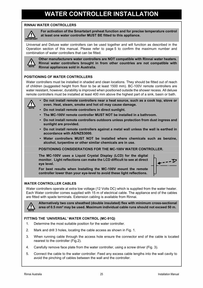
POSITIONING CONSIDERATIONS FOR THE MC-100V WATER CONTROLLER.
The MC-100V uses a Liquid Crystal Display (LCD) for the digitalmonitor. Light reflections can make the LCD difficult to see at directeye level.
For best results when Installing the MC-100V mount the remotecontroller lower than your eye-level to avoid these light reflections.
Alternatively two core sheathed (double insulated) flex with minimum cross-sectionalarea of 0.5 mm² may be used. Maximum individual cable runs should not exceed 50 m.
IMPORTANT
NOTE
NOTE
NOTE
Rinnai Australia 25 Installation Manual

WATER CONTROLLER INSTALLATION
6. Fix the water controller to the wall using the appropriate fixings as shown in Fig. 4.
7. Remove protective film from the water controller face as shown in Fig. 4 and replace face plate.
OPTIONAL PROGRAMMING FOR THE ‘UNIVERSAL’ WATER CONTROLLER (MC-91Q)
Fig. 1 Fig. 2 Fig. 3 Fig. 4
Are there four water controllers connected ?
IF NO: (You have three water controllers or fewer), go to Question 2.
IF YES: You will need to activate the fourth water controller as follows:
STEP 1: For the water controller in the KITCHEN ONLY, press and holdthe ‘Transfer’ and ‘On/Off’ buttons simultaneously (see Fig. 5)until a ‘beep’ is heard (approximately 5 seconds).
STEP 2: Check that the display on ALL FOUR water controllers is lit anddisplaying a temperature when ‘switched on’. If any ONE of thecontroller displays two dashes (see Fig. 6) repeat STEP 1.
This completes the activation procedure for the fourth controller,you may ignore Question 2.
Fig. 5
Fig. 6
Is the water heater marked to state it delivers waternot exceeding 50°C ?
IF YES: No further action required.
IF NO: You will need to program the kitchen controller to enableselection of temperatures higher than 50°C.
STEP 1: For the controller in the KITCHEN ONLY, press and hold the‘Transfer’ and ‘On/Off’ buttons simultaneously (Fig. 7) until a‘beep’ is heard (approximately 5 seconds).
STEP 2: When the controller fitted in the KITCHEN is switched On, itshould be possible to select temperatures higher than 50°C. Ifnot, repeat STEP 1.
Fig. 7
If the water controller in the kitchen is replaced, repeat STEP 1 above for thereplacement controller.
If the water controller in the kitchen is swapped with another controller (for example,the controller fitted in a bathroom), repeat STEP 1 for the controller moved from thekitchen to the bathroom. Then perform STEP 1 for the controller moved from bathroomto the kitchen.
8341
.5
120
Out
line
of W
ater
Con
trol
90
Sec
urin
gS
crew
Ø
20 C
able
Acc
ess
Connector
Controller Cable Face PlateFace Plate
Screw
Film
QUESTION
QUESTION
NOTE
Rinnai Australia 26 Installation Manual

WATER CONTROLLER INSTALLATION
FITTING THE ‘DELUXE KITCHEN’ WATER CONTROLLER (MC-100V)
FITTING THE ‘DELUXE BATHROOM’ WATER CONTROLLER (BC-100V)
1. Determine the most suitable position for the water controller (see notes page 25).
2. Use the wall mounting bracket as a template to mark and drill 3holes, locating the cable access as shown in Fig. 1.
3. Fix the mounting bracket to the wall using the appropriate fixings.
4. Run the cable through the hole in the wall.
5. Carefully remove face plate from the water controller, using a screwdriver (Fig. 2).
Fig.1
6. Connect the cable to the water controller as shown in Fig 3. At this point cables from othercontrollers (if fitted) may also be connected to the screw terminals of the Kitchen water controller(Fig. 4) eliminating the need for multiple cable runs directly to the water heater. Water controllersare not polarity sensitive. Feed any excess cable lengths into the wall cavity to avoid the pinchingof cables between the wall and the controller.
7. Fasten the controller to the wall mounting bracket as shown in Fig. 5. Avoid the over-tighteningof fixings as this may cause damage. Once secured replace the face plate.
Fig. 2 Fig. 3 Fig. 4 Fig. 5
1. Determine the most suitable position for the water controller (see notes page 25).
2. Mark and drill 3 holes, locating the cable access as shown in Fig. 1.
3. When running a cable through the access hole ensure the connectorend of the cable is located nearest to the controller (Fig. 2).
4. Affix the double sided self-adhesive seal to the back of the watercontroller (Fig. 3).
5. Carefully remove the face plate from the water controller, do this byplacing your thumbs on the front of the digital display and whilehooking your fingers behind top of plate and gently push as shown inFig. 4, DO NOT use a screwdriver as this may damage the controller.
6. Connect the cable to the water controller. Feed any excess cablelengths into the wall cavity to avoid the pinching of cables betweenthe wall and the controller.
Fig. 1
Fig. 2
7. Fix the controller to the wall using the appropriate fixings as shown in Fig. 5, avoid over-tightening of fixings as this may cause damage. Once secured replace the face plate.
Fig. 3 Fig. 4 Fig. 5
Out
line
of W
ater
Con
trolle
rS
crew
Sec
urin
g P
oint
s
128
120
Ø20
Cab
le A
cces
s
181
202
Outline of Water Controller
104
SecuringScrew
Ø20 Cable Access
Connector
Controller Cable
Backing Seal
Remove filmto expose
self-adhesive
Rinnai Australia 27 Installation Manual

WATER CONTROLLER INSTALLATION
CONNECTING COMMUNICATION CABLES TO THE WATER HEATER
Communication cables connect the water heater to water controllers and operate at an extra lowvoltage (12 Volts DC) which is supplied from the water heater. Communication cables are suppliedwith the water controllers (15m) and are fitted with spade terminals for connection to water heater. Upto two cables can be connected directly to the ‘Ezi connect’ cable connector at the water heater.Extension cables are available from Rinnai. Alternatively, two core sheathed (double insulated) flexwith minimum cross sectional area of 0.5mm² may be used. Cable lengths must not exceed 20 metres.
To connect up to two cables to the 'Ezi connect' cable connector
DO NOT attempt to connect cables to the 'Ezi connect' cable connector at the waterheater unless the electric power to the water heater is switched ‘off’ otherwise damageto electrical components may occur.
1. Isolate the electric power supply by switching the power point off and removing the power plug ofthe water heater from the electric power socket.
2. Remove the retaining screw of the 'Ezi connect' cable connector at the base of the appliance.
3. Swing the 'Ezi connect' cable connector door open and thread the cable through the weather sealof the cable access hole in the direction shown.
4. Secure the sheath of the cable with the supplied cable clamp . Loosen screw terminals and and connect the cable spade connectors to these terminals and re-tighten. Polarity is not
important, either wire colour can be connected to either terminal.
5. Return the 'Ezi connect' cable connector to the original position taking care not to damage cablewires in the process and replace the retaining screw .
Connecting Three or Four Controllers
Repeat steps 1, 2 and 3 above.
To connect three or four cables, separate all the cables to be fitted intopairs. Cut off the existing spade connectors from each pair and re-terminate each pair into a new spade connector (available from yourlocal electrical component retailer) so that there are only two setsof spade connectors (4 spade connectors in total) to be terminated.
Repeat steps 4 and 5 above.
CAUTION
A
B
C DE
A
'Ezi connect' cable connector
B
1. 2.
AA
5.
3.
4.
F
ThreeCables
FourCables
F F F
Rinnai Australia 28 Installation Manual

COMMISSIONING
TESTING WATER HEATER OPERATION
1. Before final connection of the water heater purge gas, hot water, cold water and heating looplines. Swarf in either the gas or water supplies may cause damage.
2. Turn on gas and cold water supplies.
3. Test for water leaks and gas escapes near the unit.
4. Isolate gas supply. Remove test point screw located on the gas inlet connection and attachpressure gauge.
5. Turn the power 'on' at the power point socket and turn on gas.
6. Ensure that the water controller(s) have been connected and are turned 'ON' and select themaximum available delivery temperature and open ALL available hot water outlets.
7. Operate ALL other gas appliances at their maximum gas rate, in accordance with manufacturersinstructions.
8. With all gas appliances in operation at maximum gas rate, the pressure should read between1.13 - 3.0 kPa on Natural Gas. On LPG the pressure should be 2.75 - 3.0 kPa. If the pressure islower, the gas supply is inadequate and the appliance will not operate to specification. It is theInstallers responsibility to check the gas meter, service regulator and pipe work for correctoperation/sizing and rectify as required. Note that the gas regulator on the appliance iselectronically controlled and factory pre-set. Under normal circumstances it DOES NOT needadjustment during installation.
9. Close hot water outlets.
10. Inspect and clean the filter located on the cold water inlet connection. This procedure may needto be repeated to ensure the filter remains clear, especially on new installations.
11. Confirm correct water controller operation through the complete range of functions except for thepreheat function (refer to the Operation sections of this manual).
12. Confirm hot water delivery temperature(s) using a thermometer. Ensure that temperaturesexceeding 50º C cannot be selected on controllers that are fitted to the bathrooms or ensuites.Refer “Delivery Temperature” page 30 for more details.
TESTING SMARTSTART (PREHEAT) SYSTEM OPERATIONS
1. Turn the power 'off' at the power point socket.
2. Open all available hot water outlets again until water from all outlets is cold. Then close all hotwater outlets.
3. Open the cold water inlet bleed valve and the pump bleed valve (See “GENERAL SYSTEMCOMPONENTS” on page 19, items 5 and 6) until all air pockets are released and a steadystream of water is discharged.
4. Turn the power 'on' at the power point socket.
5. Turn a water controller 'ON' and select the maximum delivery temperature.
Ensure building occupants do not have access to hot water outlets during thisprocedure. DO NOT press the preheat button during this procedure.
Ensure building occupants do not have access to hot water outlets during thisprocedure.
Ensure building occupants do not have access to hot water outlets during thisprocedure.
CAUTION
CAUTION
CAUTION
Rinnai Australia 29 Installation Manual

COMMISSIONING
6. Press the ‘preheat’ button on the water controller. The ‘preheat’ indicator next to the preheatbutton will glow indicating that the preheat system has been activated. A short time after the‘preheat’ button is pressed, the water heater should turn on.
7. Wait two minutes. This will allow the water in the pipework to be warmed.
8. Open the warm water outlet furthest away from the water heater. The water should go warm ina matter of seconds.
9. Confirm that preheat operation has ceased the ‘preheat’ indicator next to the preheat button willglow will have extinguished (preheat function is cancelled 5 minutes after activation). Theninspect and clean the strainer located on the heating loop return connection. This procedure mayneed to be repeated to ensure the strainer remains clear, especially on new installations.
10. The preheat function is cancelled 5 minutes after activation and the ‘preheat’ indicator will go out.This is to conserve energy. To reactivate, simply repeat steps 6 - 8 above.
DELIVERY TEMPERATURE
For appliances with the label “Compliant to 50°C” on the front cover
"50°C Compliant" appliances are 'factory set' to deliver a maximum temperature not exceeding50°C. However, they have an incremental adjustment mechanism that allows the installer toincrease the appliance delivery temperature incrementally from the 'Factory Set’ value totemperatures exceeding 50°C. This is intended to enable compensation for temperature losses inthe pipework between the water heater and any outlets and achieve the required temperature atthe outlet. Instructions for incremental temperature adjustment are located in the instructionpocket inside the appliance front cover.
For all other models
Rinnai continuous flow water heaters are factory pre-set to various maximum deliverytemperatures depending on model and their intended application. For the majority ofapplications, the factory pre-set temperature is appropriate. In the unlikely event it is not thissetting can be increased or decreased by the installer. Instructions for changing the maximumdelivery temperature are located in the instruction pocket inside the appliance front cover.
GAS PRESSURE SETTING
The regulator is electronically controlled and factory pre-set. Under normal circumstances it does notrequire adjustment during installation.
Make adjustments only if the unit is not operating correctly and all other possible causes for incorrectoperation have been eliminated.
Instructions for Gas Pressure Setting are to be found in the instruction pocket located inside theappliance front cover.
COMMISSIONING CHECK LIST
A commissioning check list is provided on the appliance front cover to enable the installer to stepthrough the correct commissioning procedure when installing a Rinnai Continuous Flow water heater.
The check list can also assist the installer to identify potential installation errors that may prevent theappliance from operating correctly.
The waiting time for heated water delivery will vary depending on the size and layoutof the branch line.
After testing is completed, explain to the householder the functions and operation ofthe water heater and temperature controllers (if fitted). Ensure the “PRODUCTRECORDS” on page 31 of this manual is filled in and that the booklet is handed to thecustomer. Reminding the customer to complete the Warranty Card and forward toRinnai.
NOTE
IMPORTANT
Rinnai Australia 30 Installation Manual

Rinnai Australia 31 Operation/Installation Manual
ACCESSORIES
Recess Box:
These allow the appliance to be recessed into the cavity of the wall saving precious space. Suitablefor painting.
Pipe Cover:
These hide the plumbing pipework and valves underneath the appliance. Two pipe covers can bejoined together for longer pipework.
Security Cage:
Protect the gas booster unit from theft and damage.
Security Bracket:
Prevent theft of the gas booster by securing it with the custom security bracket.
Sideways Flue Diverter
Designed to redirect flue products when the gas booster is installed on a balcony.
Contact Rinnai for further information about our accessory range and model suitability details.
Please take a moment to record the following information below for your own records.
Model No : REU-VR2626WGP-AK Serial No :
Your Retailer :
Address :
Contact Number: ( )
Purchase Date : / /
Your Installer :
Address :
Installers License No. :
Contact Number : ( )
Installation Date : / /
Certificate of Compliance No. :
PRODUCT RECORDS

32 RA TSD 10-019 Issue 3.0 02/06/11
Head Office 10-11 Walker Street,Braeside, Victoria 3195P.O. Box 460Tel: (03) 9271 6625Fax: (03) 9271 6622
National Help LinesSales & Service Tel: 1300 555 545* Fax: 1300 555 655*Spare Parts & Technical InfoTel: 1300 366 388* Fax: 1300 300 141**Cost of a local call Higher from mobile or public phones.Hot Water Service LineTel: 1800 000 340
Australia Pty. Ltd. ABN 74 005 138 769 Internet: www.rinnai.com.au E-mail: [email protected]
Rinnai has a Service and Spare Parts network with personnel who are fully trained and equipped to give the best service on your Rinnai appliance. If your appliance requires service, please call our Hot Water Service Line. Rinnai recommends that this appliance be serviced every 3 years.
U304-916X01(00)
Printed in Japan - 2011.06
CONTACT INFORMATION