Embed Size (px)
Citation preview
Operation and Safety ManualKeep this manual with the machine at all times.
Model(s)EL Series
20EL25EL30EL36EL41EL
P/N - 3120781
January 17, 2002

FOREWORD
The purpose of this manual is to provide users with the operating procedures essential for the promotion ofproper machine operation for its intended purpose. It is important to over-stress proper machine usage. Allinformation in this manual should be READ and UNDERSTOOD before any attempt is made to operate themachine. YOUR OPERATING MANUAL IS YOUR MOST IMPORTANT TOOL - Keep it with the machine.REMEMBER ANY EQUIPMENT IS ONLY AS SAFE AS THE OPERATOR.
BECAUSE THE MANUFACTURER HAS NO DIRECT CONTROL OVER MACHINE APPLICATION ANDOPERATION, PROPER SAFETY PRACTICES ARE THE RESPONSIBILITY OF THE USER AND HIS OPER-ATING PERSONNEL.
ALL INSTRUCTIONS IN THIS MANUAL ARE BASED ON THE USE OF THE MACHINE UNDER PROPEROPERATING CONDITIONS, WITH NO DEVIATIONS FROM THE ORIGINAL DESIGN. ALTERATION AND/OR MODIFICATION OF THE MACHINE IS STRICTLY FORBIDDEN, WITHOUT WRITTEN APPROVALFROM JLG INDUSTRIES, PER OSHA REGULATIONS.
THIS "SAFETY ALERT SYMBOL" IS USED TO CALL ATTENTION TO POTENTIAL HAZARDSWHICH MAY LEAD TO SERIOUS INJURY OR DEATH IF IGNORED.
Safety of personnel and proper use of the machine are of primary concern, DANGER, WARNING, CAUTION,IMPORTANT, INSTRUCTIONS and NOTE are inserted throughout this manual to emphasize these areas.They are defined as follows:
JLG INDUSTRIES, INC. MAY HAVE ISSUED SAFETY RELATED BULLETINS FOR YOUR JLG PRODUCT. CONTACT JLG INDUS-TRIES, INC. OR THE LOCAL AUTHORIZED JLG DISTRIBUTOR FOR INFORMATION CONCERNING SAFETY RELATED BULLE-TINS WHICH MAY HAVE BEEN ISSUED FOR YOUR JLG PRODUCT. ALL ITEMS REQUIRED BY THE SAFETY RELATEDBULLETINS MUST BE COMPLETED ON THE AFFECTED JLG PRODUCT.
Due to the continuous product improvements, JLG Industries, Inc. reserves the right to make specification changes without prior notification. Contact JLG Industries, Inc. for updated information.
DANGER INDICATES AN IMMINENTLY HAZARDOUS SITUA-TION WHICH, IF NOT AVOIDED WILL RESULT IN SERIOUSINJURY OR DEATH.
CAUTION INDICATES A POTENTIALLY HAZARDOUS SITUA-TION WHICH, IF NOT AVOIDED, MAY RESULT IN MINOR ORMODERATE INJURY. IT MAY ALSO BE USED TO ALERTAGAINST UNSAFE PRACTICES.
Also in this Manual "Notes:" are used to provide infor-mation of special interest.
WARNING INDICATES A POTENTIALLY HAZARDOUS SITU-ATION WHICH, IF NOT AVOIDED COULD RESULT IN SERI-OUS INJURY OR DEATH.
IMPORTANT OR INSTRUCTIONS PROCEDURES ESSENTIALFOR SAFE OPERATION AND WHICH, IF NOT FOLLOWEDMAY RESULT IN A MALFUNCTION OR DAMAGE TO THEMACHINE.
Other Publications Avaliable:Service and Manitenance Manual . . . . . . . . . 3120782Illustrated Parts Manual . . . . . . . . . . . . . . . . . 3120783

This page left intentionally blank.

INTRODUCTION - OPERATION/SAFETY PRECAUTIONS
INTRODUCTION - OPERATION/SAFETY PRECAUTIONS
All procedures herein are based on the use of themachine under proper operating conditions, with no devi-ations from original design intent ... as per OSHA regula-tions.
READ & HEED!The ownership, use, service, and/or maintenance of thismachine is subject to various federal, state and local lawsand regulations. It is the responsibility of the owner/user tobe knowledgeable of these laws and regulations and tocomply with them. The most prevalent regulations of thistype are the Federal OSHA Safety Regulations*. Listedbelow, in abbreviated form are some of the requirementsof Federal OSHA regulations in effect as of the date ofpublication of this handbook.
The listing of these requirements shall not relieve theowner/user of the responsibility and obligation to deter-mine all applicable laws and regulations and their exactwording and requirements, and to comply with therequirements. Nor shall the listing of these requirementsconstitute an assumption of responsibility of liability on thepart of JLG Industries, Inc.
1. Only trained and authorized operators shall be per-mitted to operate the aerial lift.
2. A malfunctioning lift shall be shut down untilrepaired.
3. The controls shall be plainly marked as to their func-tion.
4. The controls shall be tested each day prior to use todetermine that they are in safe operating condition.
5. Load limits specified by the manufacturer shall notbe exceeded.
6. Instruction and warning placards must be legible.
7. Aerial lifts may be "field modified" for uses other thanthose intended by the manufacturer only if certifiedin writing by the manufacturer or an equivalententity, such as a nationally recognized testing lab, tobe in conformity to applicable OSHA safety regula-tions and to be at least as safe as it was prior tomodification.
8. Aerial lifts shall not be used near electric power linesunless the lines have been deenergized or adequateclearance is maintained (see OSHA 29 CFR 1910.67and 1926.400).
9. Employees using aerial lifts shall be instructed howto recognize and avoid unsafe conditions and haz-ards.
10. Ground controls shall not be operated unless per-mission has been obtained from personnel in theplatform, except in case of an emergency.
11. Regular inspection of the job site and aerial lift shallbe performed by competent persons.
12. Personnel shall always stand on the floor of the plat-form, not on boxes, planks, railing or other devicesfor work positioning.
*Applicable Federal OSHA regulations, as of the date ofpublication of this manual include, but are not limited to,29 CFR 1910.67, 29 CFR 1926.20, 29 CFR 1926.21, 29CFR 1926.28, 29 CFR 1926.400 and 29 CFR 1926.453.Consult the current regulations for the exact wording andfull text of the requirements and contact the closest Fed-eral OSHA office for specific interpretations.
3120781 – JLG Lift – a
INTRODUCTION - MAINTENANCE SAFETY PRECAUTIONS
INTRODUCTION - MAINTENANCE SAFETY PRECAUTIONS
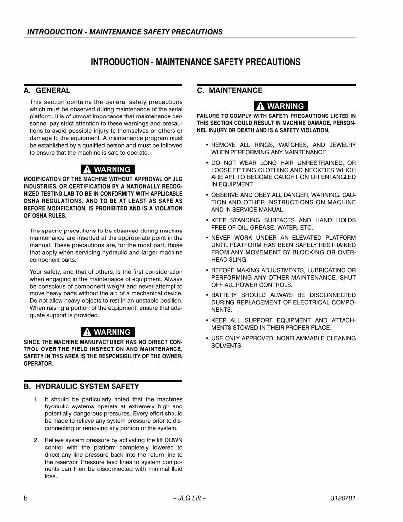
A. GENERAL
This section contains the general safety precautionswhich must be observed during maintenance of the aerialplatform. It is of utmost importance that maintenance per-sonnel pay strict attention to these warnings and precau-tions to avoid possible injury to themselves or others ordamage to the equipment. A maintenance program mustbe established by a qualified person and must be followedto ensure that the machine is safe to operate.
MODIFICATION OF THE MACHINE WITHOUT APPROVAL OF JLGINDUSTRIES, OR CERTIFICATION BY A NATIONALLY RECOG-NIZED TESTING LAB TO BE IN CONFORMITY WITH APPLICABLEOSHA REGULATIONS, AND TO BE AT LEAST AS SAFE ASBEFORE MODIFICATION, IS PROHIBITED AND IS A VIOLATIONOF OSHA RULES.
The specific precautions to be observed during machinemaintenance are inserted at the appropriate point in themanual. These precautions are, for the most part, thosethat apply when servicing hydraulic and larger machinecomponent parts.
Your safety, and that of others, is the first considerationwhen engaging in the maintenance of equipment. Alwaysbe conscious of component weight and never attempt tomove heavy parts without the aid of a mechanical device.Do not allow heavy objects to rest in an unstable position.When raising a portion of the equipment, ensure that ade-quate support is provided.
SINCE THE MACHINE MANUFACTURER HAS NO DIRECT CON-TROL OVER THE FIELD INSPECTION AND MAINTENANCE,SAFETY IN THIS AREA IS THE RESPONSIBILITY OF THE OWNER/OPERATOR.
B. HYDRAULIC SYSTEM SAFETY
1. It should be particularly noted that the machineshydraulic systems operate at extremely high andpotentially dangerous pressures. Every effort shouldbe made to relieve any system pressure prior to dis-connecting or removing any portion of the system.
2. Relieve system pressure by activating the lift DOWNcontrol with the platform completely lowered todirect any line pressure back into the return line tothe reservoir. Pressure feed lines to system compo-nents can then be disconnected with minimal fluidloss.
C. MAINTENANCE
FAILURE TO COMPLY WITH SAFETY PRECAUTIONS LISTED INTHIS SECTION COULD RESULT IN MACHINE DAMAGE, PERSON-NEL INJURY OR DEATH AND IS A SAFETY VIOLATION.
• REMOVE ALL RINGS, WATCHES, AND JEWELRYWHEN PERFORMING ANY MAINTENANCE.
• DO NOT WEAR LONG HAIR UNRESTRAINED, ORLOOSE FITTING CLOTHING AND NECKTIES WHICHARE APT TO BECOME CAUGHT ON OR ENTANGLEDIN EQUIPMENT.
• OBSERVE AND OBEY ALL DANGER, WARNING, CAU-TION AND OTHER INSTRUCTIONS ON MACHINEAND IN SERVICE MANUAL.
• KEEP STANDING SURFACES AND HAND HOLDSFREE OF OIL, GREASE, WATER, ETC.
• NEVER WORK UNDER AN ELEVATED PLATFORMUNTIL PLATFORM HAS BEEN SAFELY RESTRAINEDFROM ANY MOVEMENT BY BLOCKING OR OVER-HEAD SLING.
• BEFORE MAKING ADJUSTMENTS, LUBRICATING ORPERFORMING ANY OTHER MAINTENANCE, SHUTOFF ALL POWER CONTROLS.
• BATTERY SHOULD ALWAYS BE DISCONNECTEDDURING REPLACEMENT OF ELECTRICAL COMPO-NENTS.
• KEEP ALL SUPPORT EQUIPMENT AND ATTACH-MENTS STOWED IN THEIR PROPER PLACE.
• USE ONLY APPROVED, NONFLAMMABLE CLEANINGSOLVENTS.
b – JLG Lift – 3120781

EFFECTIVITY PAGE
EFFECTIVITY CHANGES
June 15, 1999 - Original Issue of Manual
April 20, 2000 – Revised – Added Proposition 65 to front of manual.
January 17, 2002 – Manual Revised
3120781 – JLG Lift – c

EFFECTIVITY PAGE
This Page Left Intentionally Blank
d – JLG Lift – 3120781

TABLE OF CONTENTS
SUBJECT - SECTION, PARAGRAPH PAGE NO.
INTRODUCTION - OPERATION/SAFETY PRECAUTIONS. . . . . . . . . . . . . . . . . . . . . . . . . . . . . . . . . . . .aINTRODUCTION - MAINTENANCE SAFETY PRECAUTIONS. . . . . . . . . . . . . . . . . . . . . . . . . . . . . . . . . .b
A General . . . . . . . . . . . . . . . . . . . . . . . . . . . . . . . . . . . . . . . . . . . . . . . . . . . . . . . . . . . . . . . . . . . . . .bB Hydraulic System Safety . . . . . . . . . . . . . . . . . . . . . . . . . . . . . . . . . . . . . . . . . . . . . . . . . . . . . . . . .bC Maintenance . . . . . . . . . . . . . . . . . . . . . . . . . . . . . . . . . . . . . . . . . . . . . . . . . . . . . . . . . . . . . . . . . .b
EFFECTIVITY CHANGES. . . . . . . . . . . . . . . . . . . . . . . . . . . . . . . . . . . . . . . . . . . . . . . . . . . . . . . . . . . . . .c
SECTION 1 - SAFETY PRECAUTIONS
1.1 General . . . . . . . . . . . . . . . . . . . . . . . . . . . . . . . . . . . . . . . . . . . . . . . . . . . . . . . . . . . . . . . . . . . . . .1-11.2 Electrocution Hazard. . . . . . . . . . . . . . . . . . . . . . . . . . . . . . . . . . . . . . . . . . . . . . . . . . . . . . . . . . . .1-11.3 Transporting . . . . . . . . . . . . . . . . . . . . . . . . . . . . . . . . . . . . . . . . . . . . . . . . . . . . . . . . . . . . . . . . . .1-11.4 Transport Safety . . . . . . . . . . . . . . . . . . . . . . . . . . . . . . . . . . . . . . . . . . . . . . . . . . . . . . . . . . . . . . .1-21.5 Pre-Operational Safety . . . . . . . . . . . . . . . . . . . . . . . . . . . . . . . . . . . . . . . . . . . . . . . . . . . . . . . . . .1-31.6 Operating Safety . . . . . . . . . . . . . . . . . . . . . . . . . . . . . . . . . . . . . . . . . . . . . . . . . . . . . . . . . . . . . . .1-4
SECTION 2 - PREPARATION AND INSPECTION
2.1 General . . . . . . . . . . . . . . . . . . . . . . . . . . . . . . . . . . . . . . . . . . . . . . . . . . . . . . . . . . . . . . . . . . . . . .2-12.2 Preparation For Use . . . . . . . . . . . . . . . . . . . . . . . . . . . . . . . . . . . . . . . . . . . . . . . . . . . . . . . . . . . .2-12.3 Delivery And Frequent Inspection. . . . . . . . . . . . . . . . . . . . . . . . . . . . . . . . . . . . . . . . . . . . . . . . . .2-12.4 Daily Walk-around Inspection . . . . . . . . . . . . . . . . . . . . . . . . . . . . . . . . . . . . . . . . . . . . . . . . . . . . .2-22.5 Daily Functional Check . . . . . . . . . . . . . . . . . . . . . . . . . . . . . . . . . . . . . . . . . . . . . . . . . . . . . . . . . .2-42.6 Torque Requirements . . . . . . . . . . . . . . . . . . . . . . . . . . . . . . . . . . . . . . . . . . . . . . . . . . . . . . . . . . .2-42.7 Battery Charging & Maintenance (EL-DC Models Only) . . . . . . . . . . . . . . . . . . . . . . . . . . . . . . . .2-5
SECTION 3 - USER RESPONSIBILITIES & MACHINE CONTROLS
3.1 General . . . . . . . . . . . . . . . . . . . . . . . . . . . . . . . . . . . . . . . . . . . . . . . . . . . . . . . . . . . . . . . . . . . . . .3-13.2 Personnel Training . . . . . . . . . . . . . . . . . . . . . . . . . . . . . . . . . . . . . . . . . . . . . . . . . . . . . . . . . . . . .3-13.3 Operating Characteristics And Limitations . . . . . . . . . . . . . . . . . . . . . . . . . . . . . . . . . . . . . . . . . . .3-23.4 Controls And Indicators. . . . . . . . . . . . . . . . . . . . . . . . . . . . . . . . . . . . . . . . . . . . . . . . . . . . . . . . . .3-2
SECTION 4 - MACHINE OPERATION
4.1 Machine Description . . . . . . . . . . . . . . . . . . . . . . . . . . . . . . . . . . . . . . . . . . . . . . . . . . . . . . . . . . . .4-14.2 General . . . . . . . . . . . . . . . . . . . . . . . . . . . . . . . . . . . . . . . . . . . . . . . . . . . . . . . . . . . . . . . . . . . . . .4-14.3 Machine Set-up And Operation. . . . . . . . . . . . . . . . . . . . . . . . . . . . . . . . . . . . . . . . . . . . . . . . . . . .4-24.4 Quick-Change Platform. . . . . . . . . . . . . . . . . . . . . . . . . . . . . . . . . . . . . . . . . . . . . . . . . . . . . . . . . .4-44.5 Stowing Machine. . . . . . . . . . . . . . . . . . . . . . . . . . . . . . . . . . . . . . . . . . . . . . . . . . . . . . . . . . . . . . .4-44.6 Transporting And Lifting . . . . . . . . . . . . . . . . . . . . . . . . . . . . . . . . . . . . . . . . . . . . . . . . . . . . . . . . .4-4
SECTION 5 - OPTIONAL EQUIPMENT
5.1 Optional Equipment . . . . . . . . . . . . . . . . . . . . . . . . . . . . . . . . . . . . . . . . . . . . . . . . . . . . . . . . . . . .5-15.2 Am-SE - Straddle Extension Kit – Installation . . . . . . . . . . . . . . . . . . . . . . . . . . . . . . . . . . . . . . . . .5-25.3 Am-SE - Straddle Extension Kit – Set-up And Operation . . . . . . . . . . . . . . . . . . . . . . . . . . . . . . . .5-4
SECTION 6 - EMERGENCY PROCEDURES
6.1 General Information. . . . . . . . . . . . . . . . . . . . . . . . . . . . . . . . . . . . . . . . . . . . . . . . . . . . . . . . . . . . .6-16.2 Emergency Controls And Their Locations . . . . . . . . . . . . . . . . . . . . . . . . . . . . . . . . . . . . . . . . . . .6-16.3 Emergency Operation . . . . . . . . . . . . . . . . . . . . . . . . . . . . . . . . . . . . . . . . . . . . . . . . . . . . . . . . . . .6-16.4 Incident Notification. . . . . . . . . . . . . . . . . . . . . . . . . . . . . . . . . . . . . . . . . . . . . . . . . . . . . . . . . . . . .6-2
SECTION 7 - INSPECTION AND REPAIR LOG
3120781 – JLG Lift – i
TABLE OF CONTENTS (Continued)
FIGURE NO. TITLE PAGE NO.
1-1. Electrocution Hazard. . . . . . . . . . . . . . . . . . . . . . . . . . . . . . . . . . . . . . . . . . . . . . . . . . . . . . . . . . . .1-11-2. Use Handles Provided On Mast Crossbar To Move Machine.. . . . . . . . . . . . . . . . . . . . . . . . . . . .1-21-3. Do Not Move Unit on Soft or Uneven Surfaces or Over Obstructions, Bumps, Debris, Etc.. . . . .1-21-4. Two People May Be Required on Slopes Up To Five Degrees.
Also Always Travel With Platform End On The Low Side of Slope. . . . . . . . . . . . . . . . . . . . . . . . .1-31-5. Read Your Manual. . . . . . . . . . . . . . . . . . . . . . . . . . . . . . . . . . . . . . . . . . . . . . . . . . . . . . . . . . . . . .1-31-6. Always Look in the Direction of Movement. Watch for Overhead and Other Obstructions. . . . . .1-41-7. Death or Serious Injury Could Occur from a Tip Over . . . . . . . . . . . . . . . . . . . . . . . . . . . . . . . . . .1-41-8. All Personnel Must Stand Clear When Platform Is Being Raised Or Lowered. . . . . . . . . . . . . . . .1-51-9. Falling from Platform could cause Death or Serious Injury. . . . . . . . . . . . . . . . . . . . . . . . . . . . . . .1-51-10. Be Sure Area On Tilt Back Side And Under Tilt Back Arm Is Clear Of Personnel
And/Or Obstructions Prior To Using Tilt Back. . . . . . . . . . . . . . . . . . . . . . . . . . . . . . . . . . . . . . . . .1-62-1. Daily Walk-Around Inspection. . . . . . . . . . . . . . . . . . . . . . . . . . . . . . . . . . . . . . . . . . . . . . . . . . . . .2-32-2. Battery Fluid Level. . . . . . . . . . . . . . . . . . . . . . . . . . . . . . . . . . . . . . . . . . . . . . . . . . . . . . . . . . . . . .2-52-3. Battery Box and Charger Assembly. (D.C. Model Only) . . . . . . . . . . . . . . . . . . . . . . . . . . . . . . . .2-52-4. Dual Voltage Battery Charger - Front Panel. . . . . . . . . . . . . . . . . . . . . . . . . . . . . . . . . . . . . . . . . .2-62-5. Lubrication Locations (See Table below). . . . . . . . . . . . . . . . . . . . . . . . . . . . . . . . . . . . . . . . . . . .2-72-6. Torque Chart. . . . . . . . . . . . . . . . . . . . . . . . . . . . . . . . . . . . . . . . . . . . . . . . . . . . . . . . . . . . . . . . . .2-83-1. Ground Control Station. . . . . . . . . . . . . . . . . . . . . . . . . . . . . . . . . . . . . . . . . . . . . . . . . . . . . . . . . .3-23-2. Manual Descent Valve Location.. . . . . . . . . . . . . . . . . . . . . . . . . . . . . . . . . . . . . . . . . . . . . . . . . . .3-33-3. Platform Control Station. . . . . . . . . . . . . . . . . . . . . . . . . . . . . . . . . . . . . . . . . . . . . . . . . . . . . . . . . .3-33-4. Decal Locations (Front View) . . . . . . . . . . . . . . . . . . . . . . . . . . . . . . . . . . . . . . . . . . . . . . . . . . . . .3-43-5. Decal Locations (1703778 decal from Front View). . . . . . . . . . . . . . . . . . . . . . . . . . . . . . . . . . . . .3-53-6. Decal Locations (Rear View) . . . . . . . . . . . . . . . . . . . . . . . . . . . . . . . . . . . . . . . . . . . . . . . . . . . . . .3-63-7. Decal Locations (Top View) . . . . . . . . . . . . . . . . . . . . . . . . . . . . . . . . . . . . . . . . . . . . . . . . . . . . . .3-73-8. Decal Locations (Right/Left View) . . . . . . . . . . . . . . . . . . . . . . . . . . . . . . . . . . . . . . . . . . . . . . . . . .3-84-1. Outrigger Components Installed. . . . . . . . . . . . . . . . . . . . . . . . . . . . . . . . . . . . . . . . . . . . . . . . . . .4-24-2. Quick Change Platform Mount.. . . . . . . . . . . . . . . . . . . . . . . . . . . . . . . . . . . . . . . . . . . . . . . . . . . .4-44-3. Tilt-Back Assembly Set-Up.. . . . . . . . . . . . . . . . . . . . . . . . . . . . . . . . . . . . . . . . . . . . . . . . . . . . . . .4-64-4. Loading Machine onto Bed of Pick-Up Truck. . . . . . . . . . . . . . . . . . . . . . . . . . . . . . . . . . . . . . . . .4-84-5. EL Tie Down Procedure. . . . . . . . . . . . . . . . . . . . . . . . . . . . . . . . . . . . . . . . . . . . . . . . . . . . . . . . . .4-94-6. EL Machine Tie-Down - Method 1. (Typical Flat Bed Truck) . . . . . . . . . . . . . . . . . . . . . . . . . . . . .4-104-7. EL Machine Tie-Down - Method 2 (Typical Flat Bed Truck) . . . . . . . . . . . . . . . . . . . . . . . . . . . . . .4-105-1. SE-Adapter - Wiring Kit Hole Locations for Grommet & Spring Clips (Same For Both Sides) . . .5-25-2. Straddle Adapter Wiring Harness to AM/EL Wiring Connections. . . . . . . . . . . . . . . . . . . . . . . . . .5-35-3. Straddle Extension Component Assembly. . . . . . . . . . . . . . . . . . . . . . . . . . . . . . . . . . . . . . . . . . .5-55-4. Lowering AM/EL Machine on Straddle Unit - Side Lifting Rail - Quick Release Pins. . . . . . . . . . .5-6
TABLE NO. TITLE PAGE NO.
1-1 Minimum Safe Approach Distance (to energized power lines or parts) . . . . . . . . . . . . . . . . . . . .1-12-1 Lubrication Intervals for Various Components . . . . . . . . . . . . . . . . . . . . . . . . . . . . . . . . . . . . . . . .2-74-1 Maximum Platform Capacity. (Standard Platform) . . . . . . . . . . . . . . . . . . . . . . . . . . . . . . . . . . . . .4-34-2 EL Machine Gross Weights. . . . . . . . . . . . . . . . . . . . . . . . . . . . . . . . . . . . . . . . . . . . . . . . . . . . . . .4-97-1 Inspection and Repair Log . . . . . . . . . . . . . . . . . . . . . . . . . . . . . . . . . . . . . . . . . . . . . . . . . . . . . . .7-1
ii – JLG Lift – 3120781

SECTION 1 - SAFETY PRECAUTIONS
SECTION 1. SAFETY PRECAUTIONS
1.1 GENERAL
This section prescribes the proper and safe practices formajor areas of machine usage which have been dividedinto three basic categories: Transporting, Pre-Operationand Operation. In order to promote proper usage of themachine, it is mandatory that a daily routine be estab-lished based on instruction given in this section. A mainte-nance program must also be established by a qualifiedperson and must be followed to ensure that the machineis safe to operate.
The user/operator of the machine should not accept oper-ating responsibility until this manual has been READ andUNDERSTOOD, and operating instructions of the machineunder the supervision of an experienced and qualifiedoperator, has been completed. If there is a question onapplication and/or operation, JLG Industries ProductSafety and Reliability should be consulted.
MODIFICATION OF THE MACHINE WITHOUT APPROVAL OF JLGINDUSTRIES, OR CERTIFICATION BY A NATIONALLY RECOG-NIZED TESTING LAB TO BE IN CONFORMITY WITH APPLICABLEOSHA REGULATIONS, AND TO BE AT LEAST AS SAFE ASBEFORE MODIFICATION, IS PROHIBITED AND IS A VIOLATIONOF OSHA RULES.
1.2 ELECTROCUTION HAZARD
Minimum safe approach distances (M.S.A.D.) to ener-gized (exposed or insulated) power lines and parts.
DO NOT MANEUVER MACHINE OR PERSONNEL TO DISTANCELESS THAN M.S.A.D (SEE TABLE 1-1.). ASSUME ALL ELECTRI-CAL PARTS AND WIRING ARE ENERGIZED UNLESS KNOWNOTHERWISE.
THIS MACHINE DOES NOT PROVIDE PROTECTION FROM CON-TACT WITH OR PROXIMITY TO AN ELECTRICALLY CHARGEDCONDUCTOR. MAINTAIN A CLEARANCE OF AT LEAST 10 FT.(3M) BETWEEN ANY PART OF THE MACHINE AND ANY ELECTRI-CAL LINE OR APPARATUS CARRYING UP TO 50,000 VOLTS. 1FT. (0.3M) ADDITIONAL CLEARANCE IS REQUIRED FOR EVERYADDITIONAL 30,000 VOLTS OR LESS. ALLOW FOR PLATFORMSWAY, ROCK OR SAG AND ELECTRICAL LINE SWAYING, (SEEFOLLOWING TABLE).
1.3 TRANSPORTING
Before transporting the machine the user/operator mustbe familiar with the proper procedures for transporting themachine, as well as the weight and size of the machine.
The user/operator should be familiar with the surroundingwork area and surface before transporting the machine.The work area must be a smooth, firm surface on whichmachine is capable of being leveled.
NOTE: Remember that the key to safe and proper usage iscommon sense and its careful application.
FAILURE TO COMPLY WITH SAFETY PRECAUTIONS LISTED INTHIS SECTION AND ON MACHINE MAY RESULT IN MACHINEDAMAGE, PERSONNEL INJURY OR DEATH AND IS A SAFETYVIOLATION.
Table 1-1. Minimum Safe Approach Distance(to energized power lines or parts)
VOLTAGE RANGE(PHASE TO PHASE)
MINIMUM SAFE DISTANCE - Feet [m]
0-300V – Avoid Contact
Over 300V to 50KV – 10 ft. [3 m]
Over 50KV to 200KV – 15 ft. [4.6 m]
Over 200KV to 350KV – 20 ft. [6 m]
Over 350KV to 500KV – 25 ft. [7.6 m]
Over 500KV to 750KV – 35 ft. [10.6 m]
Over 750KV to 1000KV – 45 ft. [13.7 m]
Figure 1-1. Electrocution Hazard.
3120781 – JLG Lift – 1-1
SECTION 1 - SAFETY PRECAUTIONS
1.4 TRANSPORT SAFETY• COMPLETELY EMPTY PLATFORM OF TOOLS AND
DEBRIS BEFORE MOVING MACHINE.
• FULLY LOWER PLATFORM, REMOVE AND STOW OUT-RIGGERS WHILE MACHINE IS BEING MOVED.
• NEVER ALLOW PERSONNEL IN PLATFORM WHILEMOVING MACHINE.
FAILURE TO OBSERVE THE FOLLOWING TIPPING HAZARDINSTRUCTIONS COULD CAUSE THE UNIT TO TIP OVER OR BEHARD TO CONTROL WHEN BEING MOVED, WHICH COULDRESULT IN SERIOUS INJURY OR DEATH DUE TO BEING PINNEDOR CRUSHED BY THE UNIT.
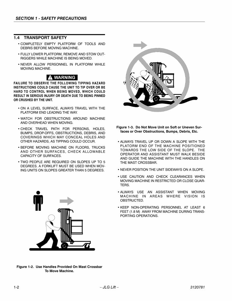
• ON A LEVEL SURFACE, ALWAYS TRAVEL WITH THEPLATFORM END LEADING THE WAY.
• WATCH FOR OBSTRUCTIONS AROUND MACHINEAND OVERHEAD WHEN MOVING.
• CHECK TRAVEL PATH FOR PERSONS, HOLES,BUMPS, DROP-OFFS, OBSTRUCTIONS, DEBRIS, ANDCOVERINGS WHICH MAY CONCEAL HOLES ANDOTHER HAZARDS, AS TIPPING COULD OCCUR.
• BEFORE MOVING MACHINE ON FLOORS, TRUCKSAND OTHER SURFACES, CHECK ALLOWABLECAPACITY OF SURFACES.
• TWO PEOPLE ARE REQUIRED ON SLOPES UP TO 5DEGREES. A FORKLIFT MUST BE USED WHEN MOV-ING UNITS ON SLOPES GREATER THAN 5 DEGREES.
• ALWAYS TRAVEL UP OR DOWN A SLOPE WITH THEPLATORM END OF THE MACHINE POSITIONEDTOWARDS THE LOW SIDE OF THE SLOPE. THEOPERATOR AND ASSISTANT MUST WALK BESIDEAND GUIDE THE MACHINE WITH THE HANDLES ONTHE MAST CROSSBAR.
• NEVER POSITION THE UNIT SIDEWAYS ON A SLOPE.
• USE CAUTION AND CHECK CLEARANCES WHENMOVING MACHINE IN RESTRICTED OR CLOSE QUAR-TERS.
• ALWAYS USE AN ASSISTANT WHEN MOVINGMACHINE IN AREAS WHERE V IS ION ISOBSTRUCTED.
• KEEP NON-OPERATING PERSONNEL AT LEAST 6FEET (1.8 M) AWAY FROM MACHINE DURING TRANS-PORTING OPERATIONS.
Figure 1-2. Use Handles Provided On Mast Crossbar To Move Machine.
Figure 1-3. Do Not Move Unit on Soft or Uneven Sur-faces or Over Obstructions, Bumps, Debris, Etc.
1-2 – JLG Lift – 3120781
SECTION 1 - SAFETY PRECAUTIONS
1.5 PRE-OPERATIONAL SAFETY
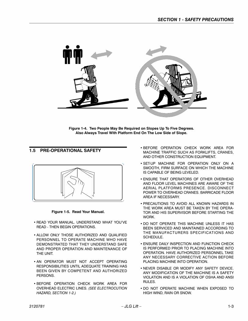
• READ YOUR MANUAL. UNDERSTAND WHAT YOU’VEREAD - THEN BEGIN OPERATIONS.
• ALLOW ONLY THOSE AUTHORIZED AND QUALIFIEDPERSONNEL TO OPERATE MACHINE WHO HAVEDEMONSTRATED THAT THEY UNDERSTAND SAFEAND PROPER OPERATION AND MAINTENANCE OFTHE UNIT.
• AN OPERATOR MUST NOT ACCEPT OPERATINGRESPONSIBILITIES UNTIL ADEQUATE TRAINING HASBEEN GIVEN BY COMPETENT AND AUTHORIZEDPERSONS.
• BEFORE OPERATION CHECK WORK AREA FOROVERHEAD ELECTRIC LINES. (SEE ELECTROCUTIONHAZARD, SECTION 1-2.)
• BEFORE OPERATION CHECK WORK AREA FORMACHINE TRAFFIC SUCH AS FORKLIFTS, CRANES,AND OTHER CONSTRUCTION EQUIPMENT.
• SET-UP MACHINE FOR OPERATION ONLY ON ASMOOTH, FIRM SURFACE ON WHICH THE MACHINEIS CAPABLE OF BEING LEVELED.
• ENSURE THAT OPERATORS OF OTHER OVERHEADAND FLOOR LEVEL MACHINES ARE AWARE OF THEAERIAL PLATFORMS PRESENCE. DISCONNECTPOWER TO OVERHEAD CRANES. BARRICADE FLOORAREA IF NECESSARY.
• PRECAUTIONS TO AVOID ALL KNOWN HAZARDS INTHE WORK AREA MUST BE TAKEN BY THE OPERA-TOR AND HIS SUPERVISOR BEFORE STARTING THEWORK.
• DO NOT OPERATE THIS MACHINE UNLESS IT HASBEEN SERVICED AND MAINTAINED ACCORDING TOTHE MANUFACTURERS SPECIFICATIONS ANDSCHEDULE.
• ENSURE DAILY INSPECTION AND FUNCTION CHECKIS PERFORMED PRIOR TO PLACING MACHINE INTOOPERATION. HAVE AUTHORIZED PERSONNEL TAKEANY NECESSARY CORRECTIVE ACTION BEFOREPLACING MACHINE INTO OPERATION.
• NEVER DISABLE OR MODIFY ANY SAFETY DEVICE.ANY MODIFICATION OF THE MACHINE IS A SAFETYVIOLATION AND IS A VIOLATION OF OSHA AND ANSIRULES.
• DO NOT OPERATE MACHINE WHEN EXPOSED TOHIGH WIND, RAIN OR SNOW.
Figure 1-4. Two People May Be Required on Slopes Up To Five Degrees.Also Always Travel With Platform End On The Low Side of Slope.
Figure 1-5. Read Your Manual.
3120781 – JLG Lift – 1-3
SECTION 1 - SAFETY PRECAUTIONS
• NEVER OPERATE OR RAISE PLATFORM WHENMACHINE IS ON A TRUCK OR OTHER VEHICLE.
• APPROVED HEAD GEAR (I.E. HARD HAT, ETC.) MUSTBE WORN WHEN REQUIRED BY ALL OPERATING ANDGROUND PERSONNEL.
• READ AND OBEY ALL DANGER, WARNINGS, CAU-T IONS AND OPERATING INSTRUCTIONS ONMACHINE AND IN THIS MANUAL.
• BE FAMILIAR WITH LOCATION AND OPERATION OFGROUND STATION AND EMERGENCY CONTROLS.
1.6 OPERATING SAFETY
• DO NOT OPERATE ANY MACHINE ON WHICH DAN-GER, WARNING, CAUTION OR INSTRUCTION PLAC-ARDS OR DECALS ARE MISSING OR ILLEGIBLE.
• NEVER EXCEED MANUFACTURERS RATED PLAT-FORM CAPACITY - REFER TO CAPACITY DECAL ONMACHINE.
• OPERATE AC UNITS WITH AN EXTENSION CORDWIRE RATED AT A MINIMUM OF 15 AMPS.
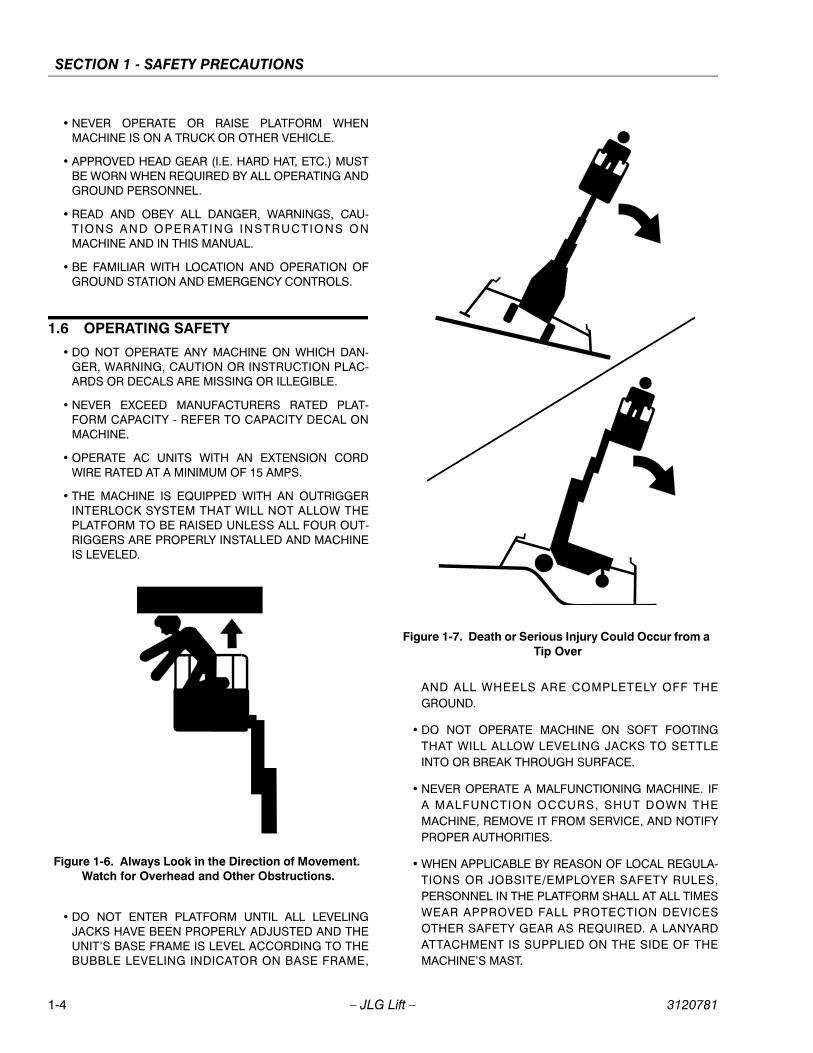
• THE MACHINE IS EQUIPPED WITH AN OUTRIGGERINTERLOCK SYSTEM THAT WILL NOT ALLOW THEPLATFORM TO BE RAISED UNLESS ALL FOUR OUT-RIGGERS ARE PROPERLY INSTALLED AND MACHINEIS LEVELED.
• DO NOT ENTER PLATFORM UNTIL ALL LEVELINGJACKS HAVE BEEN PROPERLY ADJUSTED AND THEUNIT’S BASE FRAME IS LEVEL ACCORDING TO THEBUBBLE LEVELING INDICATOR ON BASE FRAME,
AND ALL WHEELS ARE COMPLETELY OFF THEGROUND.
• DO NOT OPERATE MACHINE ON SOFT FOOTINGTHAT WILL ALLOW LEVELING JACKS TO SETTLEINTO OR BREAK THROUGH SURFACE.
• NEVER OPERATE A MALFUNCTIONING MACHINE. IFA MALFUNCTION OCCURS, SHUT DOWN THEMACHINE, REMOVE IT FROM SERVICE, AND NOTIFYPROPER AUTHORITIES.
• WHEN APPLICABLE BY REASON OF LOCAL REGULA-TIONS OR JOBSITE/EMPLOYER SAFETY RULES,PERSONNEL IN THE PLATFORM SHALL AT ALL TIMESWEAR APPROVED FALL PROTECTION DEVICESOTHER SAFETY GEAR AS REQUIRED. A LANYARDATTACHMENT IS SUPPLIED ON THE SIDE OF THEMACHINE’S MAST.
Figure 1-6. Always Look in the Direction of Movement. Watch for Overhead and Other Obstructions.
Figure 1-7. Death or Serious Injury Could Occur from a Tip Over
1-4 – JLG Lift – 3120781
SECTION 1 - SAFETY PRECAUTIONS
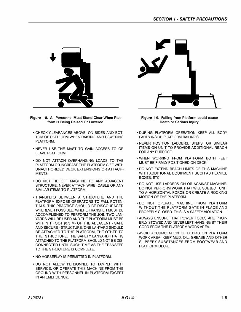
• CHECK CLEARANCES ABOVE, ON SIDES AND BOT-TOM OF PLATFORM WHEN RAISING AND LOWERINGPLATFORM.
• NEVER USE THE MAST TO GAIN ACCESS TO ORLEAVE PLATFORM.
• DO NOT ATTACH OVERHANGING LOADS TO THEPLATFORM OR INCREASE THE PLATFORM SIZE WITHUNAUTHORIZED DECK EXTENSIONS OR ATTACH-MENTS.
• DO NOT TIE OFF MACHINE TO ANY ADJACENTSTRUCTURE. NEVER ATTACH WIRE, CABLE OR ANYSIMILAR ITEMS TO PLATFORM.
• TRANSFERS BETWEEN A STRUCTURE AND THEPLATFORM EXPOSE OPERATORS TO FALL POTEN-TIALS. THIS PRACTICE SHOULD BE DISCOURAGEDWHEREVER POSSIBLE. WHERE TRANSFER MUST BEACCOMPLISHED TO PERFORM THE JOB, TWO LAN-YARDS WILL BE USED AND THE PLATFORM MUST BEWITHIN 1 FOOT (0.3 M) OF THE ADJACENT - SAFEAND SECURE - STRUCTURE. ONE LANYARD SHOULDBE ATTACHED TO THE PLATFORM, THE OTHER TOTHE STRUCTURE. THE SAFETY LANYARD THAT ISATTACHED TO THE PLATFORM SHOULD NOT BE DIS-CONNECTED UNTIL SUCH TIME AS THE TRANSFERTO THE STRUCTURE IS COMPLETE.
• NO HORSEPLAY IS PERMITTED IN PLATFORM.
• DO NOT ALLOW PERSONNEL TO TAMPER WITH,SERVICE, OR OPERATE THIS MACHINE FROM THEGROUND WITH PERSONNEL IN PLATFORM EXCEPTIN AN EMERGENCY..
• DURING PLATFORM OPERATION KEEP ALL BODYPARTS INSIDE PLATFORM RAILINGS.
• NEVER POSITION LADDERS, STEPS, OR SIMILARITEMS ON UNIT TO PROVIDE ADDITIONAL REACHFOR ANY PURPOSE.
• WHEN WORKING FROM PLATFORM BOTH FEETMUST BE FIRMLY POSITIONED ON DECK.
• DO NOT EXTEND REACH LIMITS OF THIS MACHINEWITH ADDITIONAL EQUIPMENT SUCH AS PLANKS,BOXES, ETC.
• DO NOT USE LADDERS ON OR AGAINST MACHINE.DO NOT PERFORM WORK THAT WILL SUBJECT UNITTO A HORIZONTAL FORCE OR CREATE A ROCKINGMOTION OF THE PLATFORM.
• DO NOT OPERATE MACHINE FROM PLATFORMWITHOUT THE PLATFORM GATE IN PLACE ANDPROPERLY CLOSED. THIS IS A SAFETY VIOLATION.
• ALWAYS ENSURE THAT POWER TOOLS ARE PROP-ERLY STOWED AND NEVER LEFT HANGING BY THEIRCORD FROM THE PLATFORM WORK AREA.
• AVOID ACCUMULATION OF DEBRIS ON PLATFORMWORK AREA. KEEP MUD, OIL, GREASE AND OTHERSLIPPERY SUBSTANCES FROM FOOTWEAR ANDPLATFORM DECK.
Figure 1-8. All Personnel Must Stand Clear When Plat-form Is Being Raised Or Lowered.
Figure 1-9. Falling from Platform could causeDeath or Serious Injury.
3120781 – JLG Lift – 1-5
SECTION 1 - SAFETY PRECAUTIONS
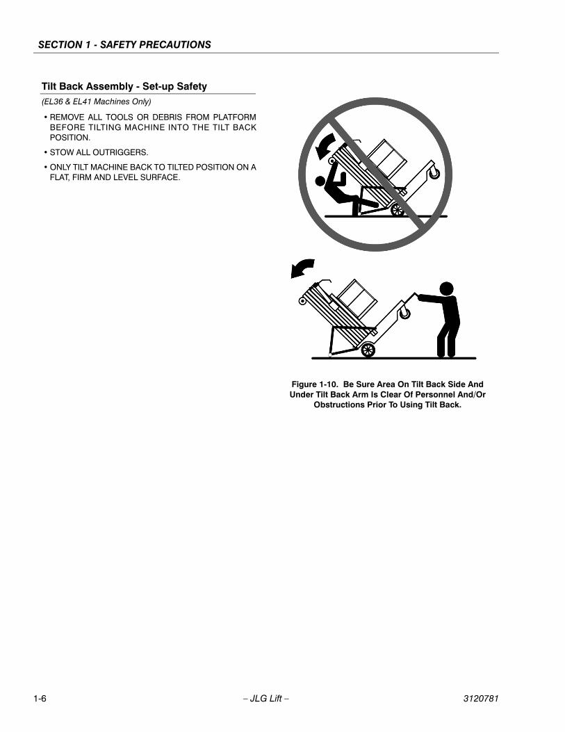
Tilt Back Assembly - Set-up Safety(EL36 & EL41 Machines Only)
• REMOVE ALL TOOLS OR DEBRIS FROM PLATFORMBEFORE TILTING MACHINE INTO THE TILT BACKPOSITION.
• STOW ALL OUTRIGGERS.
• ONLY TILT MACHINE BACK TO TILTED POSITION ON AFLAT, FIRM AND LEVEL SURFACE.
Figure 1-10. Be Sure Area On Tilt Back Side And Under Tilt Back Arm Is Clear Of Personnel And/Or
Obstructions Prior To Using Tilt Back.
1-6 – JLG Lift – 3120781

SECTION 2 - PREPARATION AND INSPECTION
SECTION 2. PREPARATION AND INSPECTION
2.1 GENERALThis section provides the necessary information neededby those personnel that are responsible to place themachine in operation readiness, and lists checks that areperformed prior to use of the machine. It is important thatthe information contained in this section be read andunderstood before any attempt is made to operate themachine. Ensure that all the necessary inspections havebeen completed successfully before placing the machineinto service. These procedures will aid in obtaining maxi-mum service life and safe operation.
SINCE THE MACHINE MANUFACTURER HAS NO DIRECT CON-TROL OVER THE FIELD INSPECTION AND MAINTENANCE, THISIS THE RESPONSIBILITY OF THE OWNER/OPERATOR.
2.2 PREPARATION FOR USEBefore a new machine is put into operation it must becarefully inspected for any evidence of damage resultingfrom shipment and inspected periodically thereafter, asoutlined in Section 2-3, Delivery and Periodic Inspection.The unit should be thoroughly checked for hydraulic leaksduring initial start-up and run. A check of all componentsshould be made to assure their security.
All preparation necessary to place the machine in opera-tion readiness status are the responsibility of manage-ment personnel. Preparation requires good commonsense, (i.e. lift works smoothly) coupled with a series ofvisual inspections. The mandatory requirements are givenin Section 2-4, Daily Walk Around Inspection.
It should be assured that the items appearing in the Deliv-ery and Frequent Inspection and Functional Check arecomplied with prior to putting the machine into service.
NOTE: This machine requires periodic safety and mainte-nance inspections. An annual inspection shall beperformed on the aerial platform no later than thir-teen (13) months from the date of the new machineinspection or prior annual inspection.
2.3 DELIVERY AND FREQUENT INSPECTIONThe following check list provides a systematic inspectionto assist in detecting defective, damaged, or improperlyinstalled parts. The check list denotes the items to beinspected and conditions to examine. Frequent inspectionshall be performed every three (3) months or more oftenwhen required by environment, severity, and frequency ofusage.
Platform Guard Rail AssembliesProperly installed; no loose or missing parts; no visibledamage.
Platform AssemblyNo visible damage; free of dirt and debris. Platform gateor slide bar functions properly on machines so equipped.
MastNo visible damage, abrasions and/or distortions; no bind-ing; mast sections free of dirt or other foreign material.Sequencing cables properly secured; no visible damage;proper cable tension.
Mast Chains & CablesNo visible damage; proper chain/cable tension; evidenceof proper lubrication. Chain/cable sheaves and sheavepins properly secured; no visible damage.
Control/(Power) Cable(s) for PlatformNo visible damage; cable properly tensioned and seatedin control cable sheaves; control cable sheaves not dam-aged and rotating freely.
Lift CylinderNo rust, nicks, scratches or foreign material on piston rod.No leakage. Manual Descent Valve secure; no visibledamage.
FrameNo visible damage; loose or missing hardware (top andunderside); outrigger sockets not bent or damaged; out-rigger beam locking pins properly secured; outriggerinterlock LED’s properly secured and undamaged.
Wheels and CastersFree rolling; no loose or missing parts; no visible damage.
3120781 – JLG Lift – 2-1
SECTION 2 - PREPARATION AND INSPECTION
Hydraulic Oil SupplyCheck the hydraulic oil level at the hydraulic fluid reservoirthrough the access hole on the side of the ground controlpanel. Maintain an oil level to the "Fill to Line" indicator onthe side of the reservoir.
If fluid level is low, see Service Manual, Section 1 - Specifi-cations; Sub-Section 1.5 “Lubrication”, "Hydraulic Oil” forrecommended oil specification use in machine.
Machine Controls - (Platform and Ground)Switches operable; no visible damage; placards secureand legible.
Batteries - (DC Models)Proper electrolyte level; cable connections tight; no visibledamage; no corrosion at battery cable connections.
Power Cord - (AC Models)No visible damage; connector and cable properlysecured.
Electric Motor/Hydraulic Pump and ValveNo leakage; unit secure.
PlacardsNo visible damage; placards secure and legible.
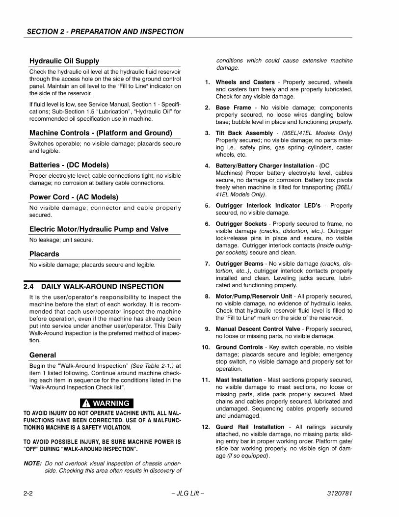
2.4 DAILY WALK-AROUND INSPECTIONIt is the user/operator’s responsibility to inspect themachine before the start of each workday. It is recom-mended that each user/operator inspect the machinebefore operation, even if the machine has already beenput into service under another user/operator. This DailyWalk-Around Inspection is the preferred method of inspec-tion.
GeneralBegin the “Walk-Around Inspection” (See Table 2-1.) atitem 1 listed following. Continue around machine check-ing each item in sequence for the conditions listed in the“Walk-Around Inspection Check list”.
TO AVOID INJURY DO NOT OPERATE MACHINE UNTIL ALL MAL-FUNCTIONS HAVE BEEN CORRECTED. USE OF A MALFUNC-TIONING MACHINE IS A SAFETY VIOLATION.
TO AVOID POSSIBLE INJURY, BE SURE MACHINE POWER IS“OFF” DURING “WALK-AROUND INSPECTION”.
NOTE: Do not overlook visual inspection of chassis under-side. Checking this area often results in discovery of
conditions which could cause extensive machinedamage.
1. Wheels and Casters - Properly secured, wheelsand casters turn freely and are properly lubricated.Check for any visible damage.
2. Base Frame - No visible damage; componentsproperly secured, no loose wires dangling belowbase; bubble level in place and functioning properly.
3. Tilt Back Assembly - (36EL/41EL Models Only)Properly secured; no visible damage; no parts miss-ing i.e.. safety pins, gas spring cylinders, casterwheels, etc.
4. Battery/Battery Charger Installation - (DCMachines) Proper battery electrolyte level, cablessecure, no damage or corrosion. Battery box pivotsfreely when machine is tilted for transporting (36EL/41EL Models Only).
5. Outrigger Interlock Indicator LED’s - Properlysecured, no visible damage.
6. Outrigger Sockets - Properly secured to frame, novisible damage (cracks, distortion, etc.). Outriggerlock/release pins in place and secure, no visibledamage. Outrigger interlock contacts (inside outrig-ger sockets) secure and clean.
7. Outrigger Beams - No visible damage (cracks, dis-tortion, etc..), outrigger interlock contacts properlyinstalled and clean. Leveling jacks secure, lubri-cated and functioning properly.
8. Motor/Pump/Reservoir Unit - All properly secured,no visible damage, no evidence of hydraulic leaks.Check that hydraulic reservoir fluid level is filled tothe "Fill to Line" mark on the side of the reservoir.
9. Manual Descent Control Valve - Properly secured,no loose or missing parts, no visible damage.
10. Ground Controls - Key switch operable, no visibledamage; placards secure and legible; emergencystop switch, no visible damage and properly set foroperation.
11. Mast Installation - Mast sections properly secured,no visible damage to mast sections, no loose ormissing parts, slide pads properly secured. Mastchains and cables properly secured, lubricated andundamaged. Sequencing cables properly securedand undamaged.
12. Guard Rail Installation - All railings securelyattached, no visible damage, no missing parts; slid-ing entry bar in proper working order. Platform gate/slide bar working properly, no visible sign of dam-age (if so equipped).
2-2 – JLG Lift – 3120781

SECTION 2 - PREPARATION AND INSPECTION
13. Platform Assembly - Secure to mast; no loose ormissing parts, no visible damage. Control andpower cables, no visible damage; cables properlytensioned and seated in control cable sheaves; con-trol cable sheaves not damaged and rotate freely
14. Platform Controls - Up/Down and Function Enablebuttons properly secured, no loose or missing parts,no visible damage. Placards secure and legible,emergency shut-off button set for operation. Controlmarkings legible; Operators manual enclosed inmanual storage tube.
In addition to the Daily Walk-Around Inspection, be sure toinclude the following as part of the daily inspection:
Figure 2-1. Daily Walk-Around Inspection.
1
1 5
3*
4
8
9
10
11
12
1314
2 6
7
* (Not Shown but attached here on back
of 36AM and 41AM Models)
Daily Walk-Around Inspection Items
1. Wheels & Casters
2. Base Frame
3. Tilt-Back Base Assy.
4. Battery Box/Charger
5. Outrigger Interlock LED’s
6. Outrigger Sockets
7. Outrigger Beams
8. Motor/Pump/Reservoir Unit
9. Manual Descent Control Valve
10. Ground Controls
11. Mast Installation
12. Guard Rail Installation
13. Platform Assembly
14. Platform Controls
3120781 – JLG Lift – 2-3

SECTION 2 - PREPARATION AND INSPECTION
Batteries Charged (DC Models)Start each day with fully charged batteries. (See Section 2-7. “Battery Charging and Maintenance.”)
Overall CleanlinessKeep oil, grease, water, etc. wiped from standing surfacesand hand holds.
PlacardsKeep all information and operating placards clean andunobstructed. Cover areas where placards are presentwhen using the machine for spraying paint or any materialwhich could cover these surfaces and reduce legibility.
Operators & Safety and ANSI Responsibilities ManualEnsure a copy of the Operators and Safety and ANSIResponsibilities manual is enclosed in the manual storagebox.
LubricationFor those parts pointed out in the Walk-Around Inspectionrequiring lubrication, (refer to the Lubrication Chart, Figure2-4., this Section), for specific time interval requirements.
2.5 DAILY FUNCTIONAL CHECK
TO AVOID INJURY DO NOT OPERATE A MACHINE UNTIL ALLMALFUNCTIONS HAVE BEEN CORRECTED. USE OF A MALFUNC-TIONING MACHINE IS A SAFETY VIOLATION.
Once the walk-around inspection is complete, a functionalcheck of all systems should be performed in an area freeof overhead and ground level obstructions. Perform afunctional check in accordance with the following proce-dures:
1. Set-up machine for operation, according to instruc-tions in Section 4-3, “Machine Set-Up & Operation”,i.e.. install outriggers, level machine, make sure allwheels are off ground, etc.
2. Enter platform, raise and lower platform 2 ft. to 3 ft.(.61m to .92 m) several times. Check for smooth ele-vation and lowering of platform.
3. With platform completely lowered, check hydraulicoil level in reservoir at ground control station. Main-tain an oil level to the "Fill to Line" indicator on theside of the reservoir. NEVER USE HYDRAULICBRAKE FLUID, refer to the Lubrication Chart, Figure7-2, for specific requirements.
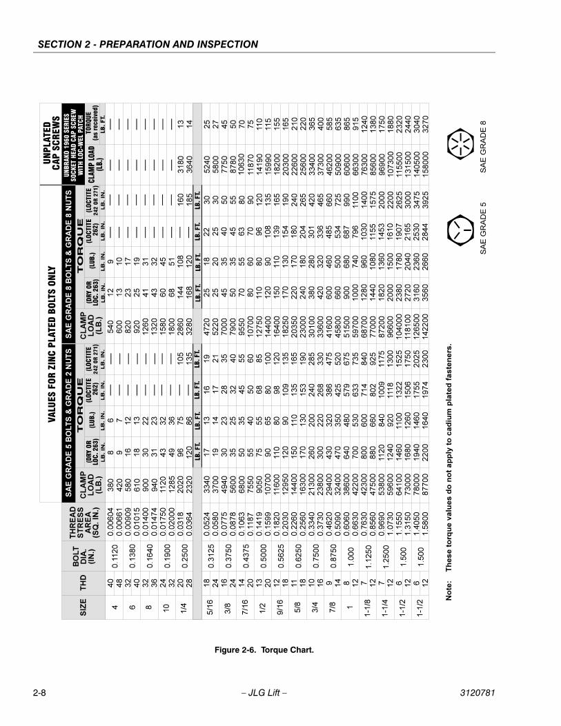
2.6 TORQUE REQUIREMENTSThe Torque Chart, Figure 2-6, consists of standard torquevalues based on bolt diameter and grade, it also specifiesdry and wet torque values in accordance with recom-mended shop practices. This chart is provided as an aidto the user/operator in the event he/she notices a condi-tion that requires prompt attention during the walk-aroundinspection or during operation until the proper service per-sonnel can be notified. Utilizing this Torque Chart in con-junction with the preventive maintenance section inSection 8, will enhance the safety, reliability and perfor-mance of the machine.
2-4 – JLG Lift – 3120781
SECTION 2 - PREPARATION AND INSPECTION
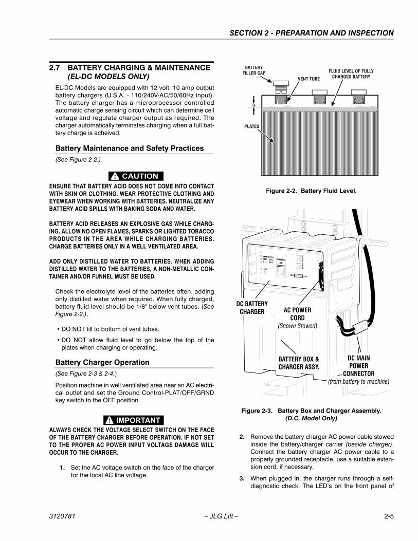
2.7 BATTERY CHARGING & MAINTENANCE (EL-DC MODELS ONLY)
EL-DC Models are equipped with 12 volt, 10 amp outputbattery chargers (U.S.A. - 110/240V-AC/50/60Hz input).The battery charger has a microprocessor controlledautomatic charge sensing circuit which can determine cellvoltage and regulate charger output as required. Thecharger automatically terminates charging when a full bat-tery charge is acheived.
Battery Maintenance and Safety Practices(See Figure 2-2.)
ENSURE THAT BATTERY ACID DOES NOT COME INTO CONTACTWITH SKIN OR CLOTHING. WEAR PROTECTIVE CLOTHING ANDEYEWEAR WHEN WORKING WITH BATTERIES. NEUTRALIZE ANYBATTERY ACID SPILLS WITH BAKING SODA AND WATER.
BATTERY ACID RELEASES AN EXPLOSIVE GAS WHILE CHARG-ING, ALLOW NO OPEN FLAMES, SPARKS OR LIGHTED TOBACCOPRODUCTS IN THE AREA WHILE CHARGING BATTERIES.CHARGE BATTERIES ONLY IN A WELL VENTILATED AREA.
ADD ONLY DISTILLED WATER TO BATTERIES. WHEN ADDINGDISTILLED WATER TO THE BATTERIES, A NON-METALLIC CON-TAINER AND/OR FUNNEL MUST BE USED.
Check the electrolyte level of the batteries often, addingonly distilled water when required. When fully charged,battery fluid level should be 1/8" below vent tubes. (SeeFigure 2-2.).
• DO NOT fill to bottom of vent tubes.
• DO NOT allow fluid level to go below the top of theplates when charging or operating.
Battery Charger Operation(See Figure 2-3 & 2-4.)
Position machine in well ventilated area near an AC electri-cal outlet and set the Ground Control-PLAT/OFF/GRNDkey switch to the OFF position.
ALWAYS CHECK THE VOLTAGE SELECT SWITCH ON THE FACEOF THE BATTERY CHARGER BEFORE OPERATION. IF NOT SETTO THE PROPER AC POWER INPUT VOLTAGE DAMAGE WILLOCCUR TO THE CHARGER.
1. Set the AC voltage switch on the face of the chargerfor the local AC line voltage.
2. Remove the battery charger AC power cable stowedinside the battery/charger carrier (beside charger).Connect the battery charger AC power cable to aproperly grounded receptacle, use a suitable exten-sion cord, if necessary.
3. When plugged in, the charger runs through a self-diagnostic check. The LED’s on the front panel of
Figure 2-2. Battery Fluid Level.
Figure 2-3. Battery Box and Charger Assembly. (D.C. Model Only)
FLUID LEVEL OF FULLYCHARGED BATTERYVENT TUBE
BATTERYFILLER CAP
PLATES
1/8"
DC BATTERYCHARGER
BATTERY BOX &CHARGER ASSY.
DC MAINPOWER
CONNECTOR(from battery to machine)
AC POWERCORD
(Shown Stowed)
3120781 – JLG Lift – 2-5

SECTION 2 - PREPARATION AND INSPECTION
the battery charger flash in the sequence noted fol-lowing;
a. First all five (5) LED’s on the face of the chargerflash three (3) times.
b. Then each LED lights in sequence.
c. Then all five (5) LED’s flash three (3) timesagain.
4. When ready to charge, the CHARGER ON LED andthe INCOMPLETE CHARGE (25%) LED on the frontpanel of the charger will light up, the charger willthen begin to charge the batteries.
NOTE: If the ABNORMAL CYCLE LED comes on and stayson at any time during the charge cycle, see sub-sec-tion following about the ABNORMAL CYCLE indica-tor LED.
5. When the battery cell voltage reaches 2.37 V/cell the80% CHARGE LED on the front panel of the chargerwill light up. The charger then continues to monitorthe increase in charge until it sees no increase, andthen terminates the charging process.
6. The CHARGE COMPLETE (100%) LED will come onwhen the charging process is finished.
7. Unplug the charger AC power cord and stow thecord in the opening in the battery/charger carrier(beside charger).
Abnormal Cycle Indicator LEDIf the ABNORMAL CYCLE indicator LED should come onduring the normal charging cycle of the batteries, it couldindicate any of the following conditions;
• The AC input to the charger was interrupted, i.e. localpower failure or charger cable was unplugged orbumped and power was interrupted intermittently.
• A dead cell or cells in the battery would prevent thecharger from sensing enough voltage to complete thebattery charge.
• One or more of the battery terminal connections looseor corroded resulting in an intermittent incomplete cir-cuit
Figure 2-4. Dual Voltage Battery Charger - Front Panel.
ABNORMAL CYCLE(YELLOW LED)
A/C VOLTAGESELECT SWITCH
CIRCUITBREAKERS
% OF CHARGEIN PROGRESS
CHARGER ON
(GREEN LED'S)
(GREEN LED)
2-6 – JLG Lift – 3120781
SECTION 2 - PREPARATION AND INSPECTION
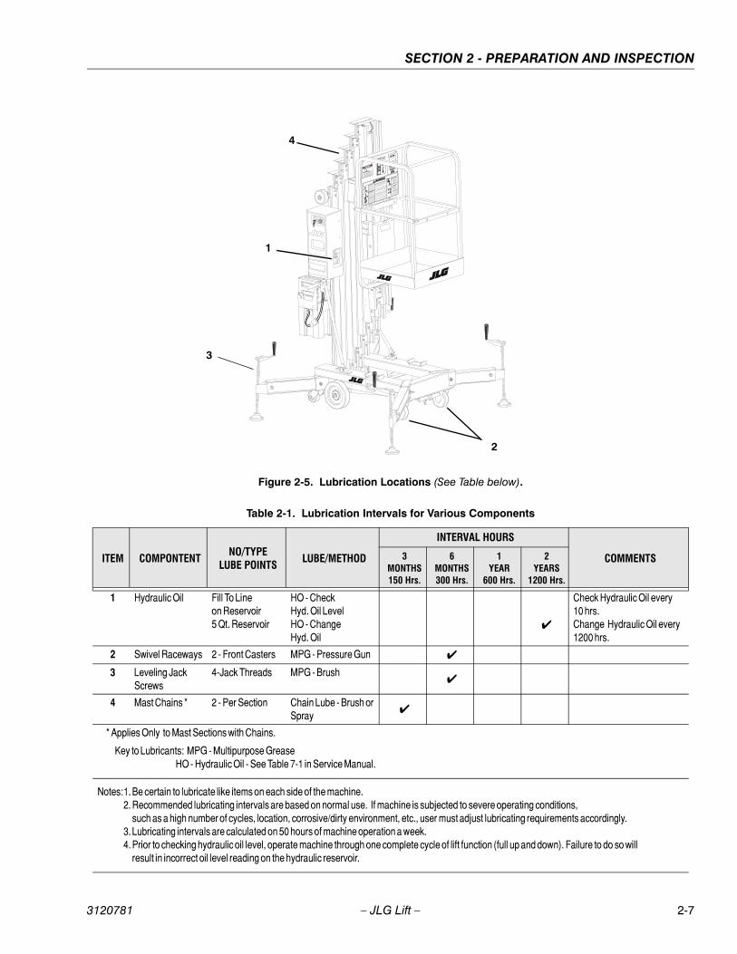
Figure 2-5. Lubrication Locations (See Table below).
1
4
2
3
Table 2-1. Lubrication Intervals for Various Components
ITEM COMPONTENTNO/TYPE
LUBE POINTSLUBE/METHOD
INTERVAL HOURS
COMMENTS3MONTHS150 Hrs.
6MONTHS300 Hrs.
1YEAR
600 Hrs.
2YEARS
1200 Hrs.
1 Hydraulic Oil Fill To Lineon Reservoir5 Qt. Reservoir
HO - CheckHyd. Oil LevelHO - ChangeHyd. Oil
✔
Check Hydraulic Oil every10 hrs.Change Hydraulic Oil every1200 hrs.
2 Swivel Raceways 2 - Front Casters MPG - Pressure Gun ✔
3 Leveling Jack Screws
4-Jack Threads MPG - Brush✔
4 Mast Chains * 2 - Per Section Chain Lube - Brush or Spray ✔
* Applies Only to Mast Sections with Chains.
Key to Lubricants: MPG - Multipurpose GreaseHO - Hydraulic Oil - See Table 7-1 in Service Manual.
Notes:1. Be certain to lubricate like items on each side of the machine.2. Recommended lubricating intervals are based on normal use. If machine is subjected to severe operating conditions,
such as a high number of cycles, location, corrosive/dirty environment, etc., user must adjust lubricating requirements accordingly.3. Lubricating intervals are calculated on 50 hours of machine operation a week.4. Prior to checking hydraulic oil level, operate machine through one complete cycle of lift function (full up and down). Failure to do so will
result in incorrect oil level reading on the hydraulic reservoir.
3120781 – JLG Lift – 2-7
SECTION 2 - PREPARATION AND INSPECTION
Figure 2-6. Torque Chart.
2-8 – JLG Lift – 3120781
SECTION 3 - USER RESPONSIBILITIES & MACHINE CONTROLS
SECTION 3. USER RESPONSIBILITIES & MACHINE CONTROLS
3.1 GENERAL
SINCE THE MANUFACTURER HAS NO DIRECT CONTROL OVERMACHINE APPLICATION AND OPERATION, CONFORMANCE WITHGOOD SAFETY PRACTICES IN THESE AREAS IS THE RESPONSI-BILITY OF THE USER AND HIS OPERATING PERSONNEL.
This section provides the necessary information neededto understand control functions. Included in this sectionare the operating characteristics and limitations, and func-tions and purposes of controls and indicators. It is impor-tant that the user/operator read and understand theproper procedures before operating the machine. Theseprocedures will aid in optimizing service life and safeoperation.
3.2 PERSONNEL TRAININGThe aerial lift is a personnel handling device; therefore, itis essential that it be operated and maintained only byauthorized personnel who have demonstrated that theyunderstand the proper operation and maintenance of themachine. It is important that all personnel who areassigned to and responsible for the operation and mainte-nance of the machine undergo a thorough training pro-gram and check out period in order to become familiarwith the characteristics prior to operating the machine.
In addition, personnel operating the machine should befamiliar with the ANSI A92.3-1990 Manual of Responsibili-ties supplied with this machine. This standard containssections outlining the responsibilities of the owners, users,operators, lessors and lessees concerning safety, training,inspection, maintenance, application and operation.
Persons under the influence of drugs or alcohol or whoare subject to seizures, dizziness or loss of physical con-trol must not be permitted to operate the machine.
Operator TrainingOperator training must include instruction in the following:
1. Use and limitations of the platform controls, groundcontrols and emergency controls.
2. Knowledge and understanding of this manual, thecontrol markings, instructions and warnings on themachine itself and the "JLG Manually PropelledAerial Work Platform Safety" video supplied with thismachine.
3. Knowledge and understanding of all safety workrules of the employer and Federal, State and Local
Statutes, including training in the recognition andavoidance of potential hazards in the work place;with particular attention to the work to be performed.
4. Proper use of all required personnel safety equip-ment.
5. Sufficient knowledge of the mechanical operation ofthe machine to recognize a malfunction or potentialmalfunction.
6. The safest means to operate near overhead obstruc-tions, other moving equipment, obstacles, depres-sions, holes, drop-offs, etc. on the supportingsurface.
7. Means to avoid the hazards of unprotected electricalconductors.
8. Any other requirements of a specific job or machineapplication.
The operator of a JLG manually propelled aerial work plat-form must not accept operating responsibility untilinstructed by a qualified person, the Operators and SafetyManual has been read and understood, as well as havingoperated the JLG manually propelled aerial work platformunder the supervision of a qualified person. A qualifiedoperator must have reviewed and understood the video,the Operators and Safety Manual, and all warning plac-ards and operating instructions on the machine, and con-tacted JLG with any questions regarding safe operation ofthe manually propelled aerial work platform. In addition,the operator and employer are responsible for complyingwith federal, state, local or provincial rules and regulationscovering the proper use and operation of this product. Ifthere is a question on application and/or operation, or toinquire about operator training, contact the Product Safetyand Reliability Department at JLG Industries, Inc. at (877)JLG-SAFE (877-554-7233).
Operator ResponsibilityThe operator must be instructed that he has the responsi-bility and authority to shut down the machine in case of amalfunction or other unsafe condition of either themachine or the job site and to request further informationfrom his supervisor or JLG Industries, Inc.
NOTE: If you require further operator and service training, inaddition to the information supplied with your aerialwork platform, please contact JLG Industries, Inc., 1JLG Drive, McConnellsburg, PA. 17233 or telephonetoll free at (877) 554-7233.
3120781 – JLG Lift – 3-1
SECTION 3 - USER RESPONSIBILITIES & MACHINE CONTROLS
3.3 OPERATING CHARACTERISTICS ANDLIMITATIONS
GeneralA thorough knowledge of the operating characteristicsand limitations of the machine is always the first require-ment for any user, regardless of user’s experience withsimilar types of equipment.
Placards(See Figures 3-3, 3-4, 3-5 & 3-6.)
Important points to remember during operation are pro-vided at the control stations by DANGER, WARNING,CAUTION, IMPORTANT and INSTRUCTION placards. Thisinformation is placed at various locations on the machinefor the express purpose of alerting personnel of potentialhazards constituted by the operating characteristics andload limitations of the machine. See Foreword at the startof this manual for a definition of the seriousness of each ofthe above placard types. See Decal Location Figures inthis section for decals which apply to this machine.
CapacitiesRaising the platform above the stowed position is basedon the following criteria:
• The machine is positioned on a smooth, firm surfaceon which the machine is capable of being leveled.
• The load is within manufacturer’s rated capacity.
• All machine systems are functioning properly.
• The machine is leveled and outriggers are properlyinstalled and locked in place as indicated by the outrig-ger interlock LED’s on the base frame.
StabilityThis machine, as originally manufactured by JLG andoperated within its rated capacity on a smooth, firm andlevel supporting surface, provides a stable aerial platformfor all platform positions.
3.4 CONTROLS AND INDICATORS
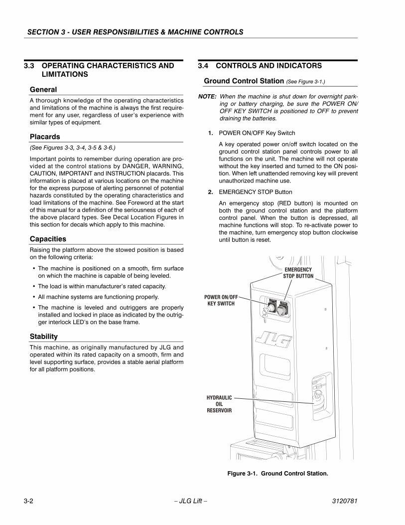
Ground Control Station (See Figure 3-1.)
NOTE: When the machine is shut down for overnight park-ing or battery charging, be sure the POWER ON/OFF KEY SWITCH is positioned to OFF to preventdraining the batteries.
1. POWER ON/OFF Key Switch
A key operated power on/off switch located on theground control station panel controls power to allfunctions on the unit. The machine will not operatewithout the key inserted and turned to the ON posi-tion. When left unattended removing key will preventunauthorized machine use.
2. EMERGENCY STOP Button
An emergency stop (RED button) is mounted onboth the ground control station and the platformcontrol panel. When the button is depressed, allmachine functions will stop. To re-activate power tothe machine, turn emergency stop button clockwiseuntil button is reset.
Figure 3-1. Ground Control Station.
EMERGENCYSTOP BUTTON
POWER ON/OFFKEY SWITCH
HYDRAULICOIL
RESERVOIR
3-2 – JLG Lift – 3120781

SECTION 3 - USER RESPONSIBILITIES & MACHINE CONTROLS
3. MANUAL DESCENT CONTROL VALVE Knob
Located at the rear and bottom of the base frame.This pull to release - spring loaded return valve (REDKnob), allows for lowering of the platform in anemergency or power failure.
4. HYDRAULIC RESERVOIR/CIRCUIT BREAKER/FUSE(located inside ground control station housing)
The hydraulic reservoir is housed inside the groundcontrol station, the hydraulic oil level can bechecked through an access hole in the side of thecover. Maintain an oil level to the "Fill to Line" indica-tor on the side of the reservoir.
NOTE: Check hydraulic oil only when platform is completelylowered and after cycling platform up/down a fewtimes.
A 20 amp reset type circuit breaker is located on thecover of the electrical box on EL-AC Models.
On EL-DC Models, a 5 Amp fuse is located inside theground control station.
Platform Control Station (See Figure 3-2.)
1. EMERGENCY STOP/SHUT-OFF Button.
An EMERGENCY STOP (RED) button is provided inorder to turn machine power on and off in the plat-form and also to turn off machine power in the eventof an emergency. Power is on when the switch is inthe reset position (turned completely clockwise -out). Power is off and all machine functions will stop,when button is depressed.
2. FUNCTION ENABLE Button.
This (GREEN) button must be depressed simulta-neously with either the UP or DOWN platform func-tion buttons in order to operate the platform.
3. Platform UP Button.
When depressed simultaneously with ENABLE but-ton raises the platform to a higher level.
4. Platform DOWN Button.
When depressed simultaneously with ENABLE but-ton lowers the platform to a lower level.
5. AUXILILARY LOWERING Device Button (OPTION)
This button located on the mast behind the platformcontrol station, will in the event of a loss of powerfrom the machines main power source, lower theplatfom from a raised position.
Figure 3-2. Manual Descent Valve Location.
1. Manual Descent Valve2. Tie-Down Lugs3. Mast
1
2
3
Figure 3-3. Platform Control Station.
EMERGENCY STOP BUTTON
PLATFORM UP BUTTON
FUNCTION ENABLE BUTTON
PLATFORM DOWN BUTTON
3120781 – JLG Lift – 3-3
SECTION 3 - USER RESPONSIBILITIES & MACHINE CONTROLS
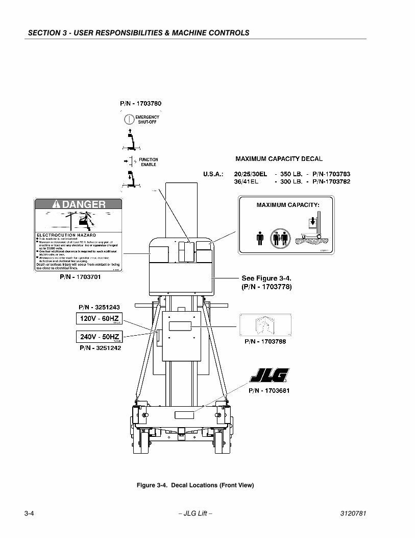
Figure 3-4. Decal Locations (Front View)
3-4 – JLG Lift – 3120781
SECTION 3 - USER RESPONSIBILITIES & MACHINE CONTROLS
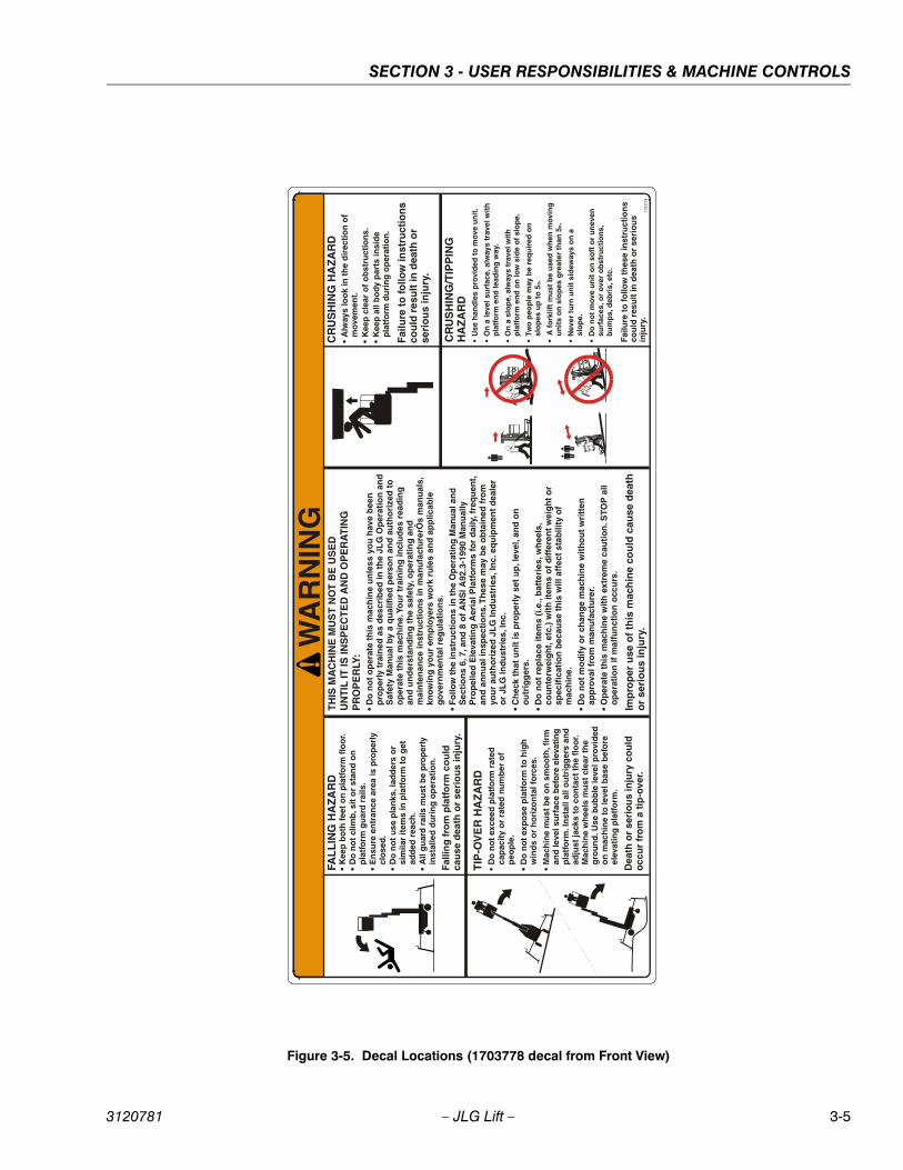
Figure 3-5. Decal Locations (1703778 decal from Front View)
WA
RN
ING
CR
US
HIN
G H
AZ
AR
D
•A
lway
s lo
ok
in t
he
dir
ecti
on
of
mov
emen
t. •
Kee
p c
lear
of
ob
stru
ctio
ns.
K
eep
all
bo
dy p
arts
insi
de
p
latf
orm
du
rin
g o
per
atio
n.
Failu
re t
o fo
llow
inst
ruct
ion
s co
uld
res
ult
in d
eath
or
seri
ou
s in
jury
.
TIP
-OV
ER
HA
ZA
RD
•
Do
no
t ex
ceed
pla
tfo
rm r
ated
ca
pac
ity
or
rate
d n
um
ber
of
p
eop
le.
•D
o n
ot
exp
ose
pla
tfo
rm t
o h
igh
w
ind
s o
r h
ori
zon
tal f
orc
es.
•M
ach
ine
mu
st b
e o
n s
mo
oth
, fir
m
and
leve
l su
rfac
e b
efo
re e
leva
tin
g
pla
tfo
rm. I
nst
all a
ll o
utr
igg
ers
and
ad
just
jack
s to
co
nta
ct t
he
flo
or.
M
ach
ine
wh
eels
mu
st c
lear
th
e
gro
un
d. U
se b
ub
ble
leve
l pro
vid
ed
on
mac
hin
e to
leve
l bas
e b
efo
re
elev
atin
g p
latf
orm
.
Dea
th o
r se
rio
us
inju
ry c
ou
ld
occ
ur
fro
m a
tip
-ove
r.
CR
US
HIN
G/T
IPP
ING
H
AZ
AR
D
•U
se h
and
les
pro
vid
ed t
o m
ove
un
it.
•O
n a
leve
l su
rfac
e, a
lway
s tr
avel
wit
h
pla
tfo
rm e
nd
lead
ing
way
.
•O
n a
slo
pe,
alw
ays
trav
el w
ith
p
latf
orm
en
d o
n lo
w s
ide
of
slo
pe.
•Tw
o p
eop
le m
ay b
e re
qu
ired
on
sl
op
es u
p t
o 5
. o
• A
fork
lift
mu
st b
e u
sed
wh
en m
ovin
g
un
its
on
slo
pes
gre
ater
th
an 5
. o
•N
ever
tu
rn u
nit
sid
eway
s o
n a
slo
pe.
•D
o n
ot
mov
e u
nit
on
so
ft o
r u
nev
en
surf
aces
, or
over
ob
stru
ctio
ns,
bu
mp
s, d
ebri
s, e
tc.
Failu
re t
o fo
llow
th
ese
inst
ruct
ion
s co
uld
res
ult
in d
eath
or
seri
ou
s in
jury
.
TH
IS M
AC
HIN
E M
US
T N
OT
BE
US
ED
U
NT
IL IT
IS IN
SP
EC
TE
D A
ND
OP
ER
AT
ING
P
RO
PE
RLY
: •
Do
no
t o
per
ate
this
mac
hin
e u
nle
ss y
ou
hav
e b
een
p
rop
erly
tra
ined
as
des
crib
ed in
th
e JL
G O
per
atio
n a
nd
S
afet
y M
anu
al b
y a
qu
alif
ied
per
son
an
d a
uth
ori
zed
to
o
per
ate
this
mac
hin
e. Y
ou
r tr
ain
ing
incl
ud
es r
ead
ing
an
d u
nd
erst
and
ing
th
e sa
fety
, op
erat
ing
an
d
mai
nte
nan
ce in
stru
ctio
ns
in m
anu
fact
ure
rÕs
man
ual
s,
know
ing
yo
ur
emp
loye
rs w
ork
ru
les
and
ap
plic
able
g
over
nm
enta
l reg
ula
tio
ns.
•
Fo
llow
th
e in
stru
ctio
ns
in t
he
Op
erat
ing
Man
ual
an
d
Sec
tio
ns
6, 7
, an
d 8
of
AN
SI A
92.3
-199
0 M
anu
ally
P
rop
elle
d E
leva
tin
g A
eria
l Pla
tfo
rms
for
dai
ly, f
req
uen
t,
and
an
nu
al in
spec
tio
ns.
Th
ese
may
be
ob
tain
ed f
rom
yo
ur
auth
ori
zed
JL
G In
du
stri
es, I
nc.
eq
uip
men
t d
eale
r
or
JLG
Ind
ust
ries
, In
c.
•C
hec
k th
at u
nit
is p
rop
erly
set
up
, lev
el, a
nd
on
o
utr
igg
ers.
•
Do
no
t re
pla
ce it
ems
(i.e
., b
atte
ries
, wh
eels
, co
un
terw
eig
ht,
etc.
) w
ith
item
s o
f d
iffe
ren
t w
eig
ht
or
sp
ecif
icat
ion
bec
ause
th
is w
ill a
ffec
t st
abili
ty o
f m
ach
ine.
•
Do
no
t m
od
ify
or
chan
ge
mac
hin
e w
ith
ou
t w
ritt
en
app
rova
l fro
m m
anu
fact
ure
r. •
Op
erat
e th
is m
ach
ine
wit
h e
xtre
me
cau
tio
n. S
TOP
all
o
per
atio
n if
mal
fun
ctio
n o
ccu
rs.
Imp
rop
er u
se o
f th
is m
ach
ine
cou
ld c
ause
dea
th
or
seri
ou
s in
jury
.
FAL
LIN
G H
AZ
AR
D
•K
eep
bo
th f
eet
on
pla
tfo
rm f
loo
r. •
Do
no
t cl
imb
, sit
or
stan
d o
n
pla
tfo
rm g
uar
d r
ails
. •
En
sure
en
tran
ce a
rea
is p
rop
erly
cl
ose
d.
•D
o n
ot
use
pla
nks
, lad
der
s o
r
sim
ilar
item
s in
pla
tfo
rm t
o g
et
add
ed r
each
. •
All
gu
ard
rai
ls m
ust
be
pro
per
ly
inst
alle
d d
uri
ng
op
erat
ion
.
Falli
ng
fro
m p
latf
orm
co
uld
ca
use
dea
th o
r se
rio
us
inju
ry.
1703
778
3120781 – JLG Lift – 3-5

SECTION 3 - USER RESPONSIBILITIES & MACHINE CONTROLS
Figure 3-6. Decal Locations (Rear View)
3-6 – JLG Lift – 3120781
SECTION 3 - USER RESPONSIBILITIES & MACHINE CONTROLS
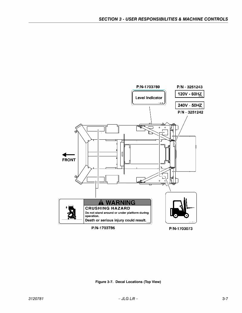
Figure 3-7. Decal Locations (Top View)
3120781 – JLG Lift – 3-7
SECTION 3 - USER RESPONSIBILITIES & MACHINE CONTROLS
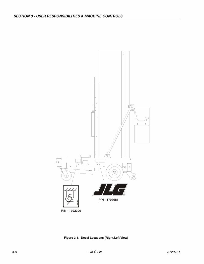
Figure 3-8. Decal Locations (Right/Left View)
1702
300 P/N - 1703681
P/N - 1702300
3-8 – JLG Lift – 3120781

SECTION 4 - MACHINE OPERATION
SECTION 4. MACHINE OPERATION
4.1 MACHINE DESCRIPTION The EL Series line of machines are a manually propelledmachine, with an aerial work platform mounted to an ele-vating aluminum mast mechanism. The mast is raised andlowered by a hydraulic cylinder extending between mastsection-1 and -2, the remaining mast sections are propor-tionally extended and retracted using steel chains andcables. Hydraulic pressure is supplied to the lift cylinderby an electrically powered hydraulic pump. All EL Seriesfeature a steel base frame with aluminum outrigger beamsmanually leveled and configured in an “X” pattern. Theplatform may be raised only when lift is positioned onsmooth, firm surface on which the machine is capable ofbeing leveled. The personnel lift’s intended purpose is toprovide personnel (with their tools and supplies) access toareas above ground level.
The JLG personnel lift has a primary operator control sta-tion in the platform. From this control station the operatorcan raise and lower the platform. A ground control stationis also provided. This station contains a keyed power on/off switch, an emergency stop button and an emergency/manual decent valve which enables the platform to belowered to the ground in an emergency, if the operator inthe platform is unable to do so, or if a power failure shouldoccur.
Instructions and warnings are posted adjacent to bothoperator control stations and at other places on themachine. It is extremely important that the user/operatorknow what instructions and warnings are placed on themachine and in the manual. And that these instructionsand warning’s be reviewed periodically. The JLG person-nel lift is designed to provide efficient and safe operationwhen maintained and operated in accordance withinstructions and warnings on the machine, in the Operat-ing, Safety and Maintenance Manual and all jobsite andgovernment rules and regulations.
As with any type of machinery, the operator is veryimportant to efficient and safe operation.It is absolutelynecessary that the JLG lift be regularly maintained inaccordance with this manual.
Any evidence of lack of maintenance, malfunction, exces-sive wear, damage or modification to the machine must bereported immediately to the machine owner, the jobsitesupervisor or safety manager and that the machine betaken out of service until all discrepancies are corrected.
The JLG personnel lift is not intended to be used to liftmaterial other than supplies which personnel in the plat-form require to do their job. Supplies or tools whichextend outside the platform are prohibited except for JLGapproved recepticals. The personnel lift must not be usedas a forklift, crane, or support for overhead structure.
The total platform rated capacity must be uniformly distrib-uted in the center of the platform. This means that the totalcombined weight of personnel, tools and supplies loadedinto the platform must not exceed the platform total ratedcapacity.
4.2 GENERALThis section provides the necessary information neededto operate the machine. Included in this section are theprocedures for set-up, starting, stopping, raising, lower-ing, platform loading and transporting. It is important thatthe user read and understand the proper proceduresbefore operating the machine. Although some of the moreimportant operating safety precautions will be listed in thefollowing paragraph sections, it is extremely important allsafety precautions in Section 1 - Safety Precautions beread and understood before operating machine. If a “DailyWalk-Around Inspection”, (see Section 2-4.) has not beencompleted, perform this inspection before starting set-upand operation. The operator must also be familiar with allmachine controls as described in Section 3 - User/Opera-tor Responsibilities and Machine Controls.
3120781 – JLG Lift – 4-1
SECTION 4 - MACHINE OPERATION
4.3 MACHINE SET-UP AND OPERATIONThe following sequence of set-up procedures must be fol-lowed to safely operate this machine.
1. Position machine in work area. Work area must be asmooth, firm surface on which machine is capable ofbeing leveled.
NOTE: If AC powered machine, connect machine to agrounded AC receptical with a heavy duty extensioncord equipped with an equipment grounding conduc-tor, also the cord must be capable of handling themaximum amperage draw of the machine’s electricpump motor.If DC powered machine, be sure battery box assem-bly is installed, battery is charged and connected tothe machine’s DC receptacle.
2. Set Power On/Off Key Switch to the ON position atthe ground control station.
3. Check if both Emergency Stop Switches, one onplatform control station and one on ground controlstation are in reset position for operation.
4. Install outriggers, see steps following.
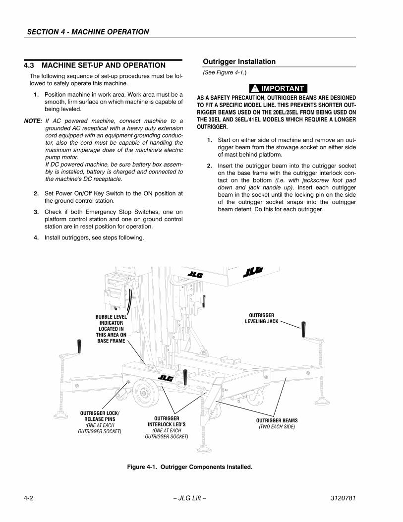
Outrigger Installation(See Figure 4-1.)
AS A SAFETY PRECAUTION, OUTRIGGER BEAMS ARE DESIGNEDTO FIT A SPECIFIC MODEL LINE. THIS PREVENTS SHORTER OUT-RIGGER BEAMS USED ON THE 20EL/25EL FROM BEING USED ONTHE 30EL AND 36EL/41EL MODELS WHICH REQUIRE A LONGEROUTRIGGER.
1. Start on either side of machine and remove an out-rigger beam from the stowage socket on either sideof mast behind platform.
2. Insert the outrigger beam into the outrigger socketon the base frame with the outrigger interlock con-tact on the bottom (i.e. with jackscrew foot paddown and jack handle up). Insert each outriggerbeam in the socket until the locking pin on the sideof the outrigger socket snaps into the outriggerbeam detent. Do this for each outrigger.
Figure 4-1. Outrigger Components Installed.
OUTRIGGERINTERLOCK LED’S
(ONE AT EACH
OUTRIGGER SOCKET)
OUTRIGGER LOCK/RELEASE PINS(ONE AT EACH
OUTRIGGER SOCKET)
OUTRIGGER BEAMS(TWO EACH SIDE)
BUBBLE LEVELINDICATORLOCATED IN
THIS AREA ONBASE FRAME
OUTRIGGERLEVELING JACK
4-2 – JLG Lift – 3120781
SECTION 4 - MACHINE OPERATION
3. With all outriggers inserted and secured with it’slocking pin, crank each outrigger jack down the min-imum amount necessary for all the base wheels toclear the floor. The RED outrigger interlock LED’s(located on side of base frame near each outriggersocket) will illuminate when the outrigger beaminterlock contact (on bottom of each beam) is incontact with the socket contacts (on the bottom ofeach outrigger socket).
4. With all the base wheels on the machine off the sur-face, check the bubble level on the base frame, andlevel machine accordingly (indicated by the bubblebeing centered inside the black circle on the bubblelevel indicator).
MACHINE MUST BE LEVEL, CHECK THAT ALL FOUR WHEELS AREOFF THE FLOOR. ALSO ALL FOUR OUTRIGGER INTERLOCK LED’SMUST BE ILLUMINATED BEFORE POWER WILL BE SUPPLIED TOTHE PLATFORM CONTROL PANEL.
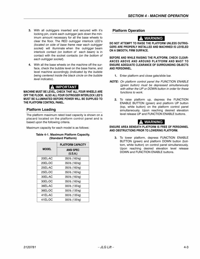
Platform LoadingThe platform maximum rated load capacity is shown on aplacard located on the platform control panel and isbased upon the following criteria.
Maximum capacity for each model is as follows:
Platform Operation
DO NOT ATTEMPT TO RAISE THE PLATFORM UNLESS OUTRIG-GERS ARE PROPERLY INSTALLED AND MACHINED IS LEVELEDON A SMOOTH, FIRM SURFACE.
BEFORE AND WHILE RAISING THE PLATFORM, CHECK CLEAR-ANCES ABOVE AND AROUND PLATFORM AND MAST TOENSURE ADEQUATE CLEARANCE OF SURROUNDING OBJECTSAND PERSONNEL.
1. Enter platform and close gate/slide bar.
NOTE: On platform control panel the FUNCTION ENABLE(green button) must be depressed simultaneouslywith either the UP or DOWN button in order for thesefunctions to work.
2. To raise platform up, depress the FUNCTIONENABLE BUTTON (green) and platform UP button(top, white button) on the platform control panelsimultaneously. Upon reaching desired elevationlevel release UP and FUNCTION ENABLE buttons.
ENSURE AREA BENEATH PLATFORM IS FREE OF PERSONNELAND OBSTRUCTIONS PRIOR TO LOWERING PLATFORM.
3. To lower platform, depress FUNCTION ENABLEBUTTON (green) and platform DOWN button (bot-tom, white button) on control panel simultaneously.Upon reaching desired elevation level releaseDOWN and FUNCTION ENABLE buttons.
Table 4-1. Maximum Platform Capacity.(Standard Platform)
MODEL
PLATFORM CAPACITY
ANSI SPEC(U.S.A.)
20EL-AC 350 lb. (160 kg)
20EL-DC 350 lb. (160 kg)
25EL-AC 350 lb. (160 kg)
25EL-DC 350 lb. (160 kg)
30EL-AC 350 lb. (160 kg)
30EL-DC 350 lb. (160 kg)
36EL-AC 300 lb. (135 kg)
36EL-DC 300 lb. (135 kg)
41EL-AC 300 lb. (135 kg)
41EL-DC 300 lb. (135 kg)
3120781 – JLG Lift – 4-3

SECTION 4 - MACHINE OPERATION
4.4 QUICK-CHANGE PLATFORM(See Figure 4-2.)
This design EL model is equipped with quick-change plat-form mounts which will allow quick removal and installa-tion of the currently available quick-change platforms. Thefollowing procedures describe platform removal andinstallation:
Platform Removal
1. Remove both pins securing the lower platform sup-port rail to the platform lower mount.
2. Remove both pins securing the upper platform sup-port rail to the platform upper mount.
3. Using either suitable lifting equipment, capable oflifting the weight of the mounted platform, or anotherperson, swing the lower platform support rail for-ward, away from the mast to clear the platform lowermount, then lift the upper platform support rail upand out of the platform upper mount. Move the plat-form clear of the machine and carefully set the plat-form on its base out of the way.
Platform Installation
1. Using either two people or suitable lifting equipmentcapable of lifting the weight of the unmounted plat-form, lift the platform and set the platforms’ uppersupport rail into the upper platform mount on themast.
2. Swing the platform lower support rail into the lowerplatform mount on the mast.
3. Secure the platform support rails with the two (2)platform upper mount pins, and the two (2) lowerplatform mount pins.
The platform is now ready for operation.
4.5 STOWING MACHINE
1. Ensure that platform is fully lowered, turn POWERON/OFF key switch (on the Ground Control Station)to the OFF position.
2. Place outrigger beams in stowage sockets on bothsides of mast, behind platform.
WHEN MOVING MACHINE PLEASE FOLLOW ALL SAFETY PRECAU-TIONS DESCRIBED IN SECTION 1-5, “TRANSPORT SAFETY” OFTHIS MANUAL. ALSO SEE SECTION 4-6, “TRANSPORTING ANDLIFTING” FOR PROPER PROCEDURES FOR TRANSPORTING.
3. Move machine to a well-protected and well-venti-lated area. If necessary, cover the machine so it willbe protected if in a hostile environment.
4. Chock at least two wheels when parking machine foran extended period of time.
5. If necessary, remove key from Ground Control PanelPOWER ON/OFF key switch to disable machinefrom unauthorized use.
NOTE: If required, DC machine batteries should be chargedin preparation for next work day in accordance withSection 2-7, “Battery Charging” (DC Machines).
4.6 TRANSPORTING AND LIFTING
GeneralAll EL models may be transported from worksite to work-site using any of the following methods:
• Pushing the machine around on its base wheels.
• Pushing the machine around in Tilt-Back mode. (Seenote following)
• Move with a forklift truck using the forklift pocketsunder the mast end of the baseframe.
Figure 4-2. Quick Change Platform Mount.
PLATFORMUPPER MOUNT
UPPER MOUNTPINS
PLATFORMLOWER MOUNT
LOWER MOUNTPINS
4-4 – JLG Lift – 3120781
SECTION 4 - MACHINE OPERATION
• Load the machine on the back of a pickup truck usingbuilt-in load-bar/slide-pad assembly.
NOTE: Due to the stowed height of the 35EL and 41ELmodels, a permanently attached tilt-back assemblyallows the operator to tilt the machine to move itthrough standard size doorways.
Transporting by Pushing
CAREFULLY REVIEW ALL SAFETY PRECAUTIONS NOTED IN SEC-TIONS 1-3 & 1-4, “TRANSPORT SAFETY”, BEFORE ATTEMPTING TOMOVE MACHINE.
The standard machine’s base frame is equipped with loadbearing wheels mounted on a straight axle at the mastend of the machine; and a pair of heavy duty swivelcaster wheels mounted on the frame at the platform endof the machine. It is important to closely follow the instruc-tions mentioned in the following WARNING note to ensuresafe transport of unit when pushing.
FAILURE TO HEED THE FOLLOWING INSTRUCTIONS COULDCAUSE THE UNIT TO TIP OVER OR BE HARD TO CONTROLWHEN BEING MOVED WHICH COULD RESULT IN SERIOUSINJURY OR DEATH DUE TO BEING PINNED OR CRUSHED BYUNIT.
• WALK BEHIND THE UNIT TO PUSH AND STEERUSING THE HANDLES ON THE MAST CROSSBAR.
• ON A LEVEL SURFACE, ALWAYS TRAVEL WITH THEPLATFORM END LEADING THE WAY.
• ON A SLOPE, ALWAYS TRAVEL WITH THE PLATFORMEND ON THE LOW SIDE OF THE SLOPE.
• TWO PEOPLE ARE REQUIRED ON SLOPES UP TO 5DEGREES, A FORKLIFT MUST BE USED WHEN MOV-ING UNITS ON SLOPES GREATER THAN 5 DEGREES.
• NEVER POSITION THE UNIT SIDEWAYS ON A SLOPE.
• DO NOT MOVE UNIT ON SOFT OR UNEVEN SUR-FACES, OR OVER OBSTRUCTIONS, BUMPS, DEBRIS,ETC.
BEFORE MOVING A MACHINE BY PUSHING, IF NECESSARYREMOVE OUTRIGGERS AND SECURE ANY TOOLS OR OBJECTSWHICH MAY OTHERWISE FALL OFF AND CAUSE INJURY OR BEDAMAGED DURING TRANSPORT.
Tilt-Back Assembly Set-up (EL36/EL41)(See Figure 4-3.)
CAREFULLY REVIEW ALL SAFETY PRECAUTIONS NOTED IN SEC-TION 1-6, OPERATING SAFETY, SUB-SECTION -“TILT BACK ASSEM-BLY SAFETY”, BEFORE ATTEMPTING TO TILT MACHINE.
1. (Photo 1) Move machine to an area clear and free ofobstructions in direction machine is to be tilted.
PLATFORM MUST BE FULLY LOWERED, AND OUTRIGGER BEAMSMUST BE REMOVED FROM OUTRIGGER SOCKETS IN BASE FRAMETO PERFORM THIS OPERATION, (PREFERABLY PLACE BEAMS INSTOWAGE SOCKETS ON EACH SIDE OF PLATFORM).
2. (Photo 2) Hold on to the tilt-back assembly andremove the release pins (located on both ends of themast support crossbar) from the mast supportbracket on the back of mast.
3. (Photo 3) Carefully lower the tilt-back assembly asfar as it will go.
4. (Photo 4) Grasp either of the gas spring assemblieson the tilt-back assembly and pull upward out ofspring clip.
5. (Photo 4) Guide the groove pins (on the free end ofthe gas spring assy.) into the slot on the mast cross-bar support bracket attached to the rear of the mast,the tilt-back assembly will need to be lifted some toperform this operation. Secure gas spring cylindersto the mast support bracket with the release pins,(same pins used to secure the tilt-back assy. to themast support bracket cross bar). Do the same withthe other side gas spring assembly.
6. (Photo 5) To tilt machine back on the tilt-backassembly, go to the platform end of the machine andlocate the T-handle lifting bar just below the baseframe under front of platform.
7. (Photo 5) Lift the spring-loaded locking pin (insidebase frame under platform) on the outer sleeve ofthe T-handle bar and slide the handle out until thelocking pin locks the T-handle bar in the extendedposition.
ON DC MODELS ENSURE BATTERY BOX/CHARGER ASSEMBLY ISNOT OBSTRUCTED AND IS CLEAR TO SWING ONCE MACHINE ISTILTED.
3120781 – JLG Lift – 4-5

SECTION 4 - MACHINE OPERATION
Photo 1 Photo 2
Photo 3 Photo 4
Photo 5 Photo 6
Figure 4-3. Tilt-Back Assembly Set-Up.
4-6 – JLG Lift – 3120781
SECTION 4 - MACHINE OPERATION
8. (Photo 6) With both hands on the grips of the T-han-dle lifting bar, carefully lift up on the platform end ofthe base pivoting the machine on the rear wheelsuntil it engages the gas spring assembly, keep liftinguntil machine rests fully on the tilt-back assembly.
9. The machine may now be moved around on the tilt-back assembly. The castor wheels on the tilt-backassembly can be allowed to rotate freely or can belocked in position at 90 degree intervals.
Pickup Truck Loading Device (Option)(See Figure 4-4.)
NOTE: The stowed mast height of the 36EL and 41ELexceeds the length of most pick-up truck beds. JLGdoes not recommend transporting those models bypick-up truck.
All EL models are capable of being transported in the bedof a standard pickup truck. However the lift must beequipped the optional loading device component kit. Thelifts can be loaded and unloaded by one person, See Fig.4-4. showing an operator loading an EL model into thebed of a pickup truck.
NOTE: It is recommended that 3/4" (19mm) to 1" (25.4mm)thick plywood be placed in the truck bed and outonto the tailgate. This will result in a smooth rollingsurface while loading machine into the truck bed andalso helps distribute the machine weight more evenlyacross the truck tailgate to avoid tailgate damage.
1. Park truck on a firm, smooth, level surface with tail-gate open. Roll the machine over to truck tailgatewith the mast end (back of machine) towards thetailgate.
REMOVE OR SECURE ANY ITEMS ATTACHED TO THE MACHINETHAT MAY OBSTRUCT ENTRY OF THE LIFT ONTO THE TRUCK BED;OR THAT MAY FALL OFF AND BE DAMAGED OR CAUSE INJURY TOYOURSELF OR NEARBY PERSONNEL.
2. On DC machines the battery charger/ storage boxmust be removed and placed on the truck sepa-rately for transport.
3. (Photo 1) Adjust the load bar device on the back ofthe mast so the bar sets approximately 1 to 2 inchesabove tailgate height. Adjust by pulling out on thespring loaded locking pin and raising or lowering theloading device. BE CERTAIN THE LOADING DE-VICE IS LOCKED IN PLACE AT THE PROPERHEIGHT.
4. (Photo 1) Push machine in against tailgate.
5. (Photo 2) On platform end of machine, extend T-han-dle load lifting bar out from under base frame bypulling down on the spring loaded locking pin.Extend the handle out until the locking pin alignswith hole in T-handle bar (when extended). Lock lift-ing bar in place.
6. (Photo 3) Begin lifting machine onto the tailgate ofthe truck with the T-handle lifting bar. As machinebegins to tilt be certain the load bar is properlyengaging the truck tailgate.
7. (Photo 4) Continue lifting and pushing machine ontothe truck tailgate. As the bar of the loading devicepivots the machine horizontally onto the truck bed,firmly grasp the machine by the base frame (Photo4) pushing machine all the way into truck bed on thewheels attached to the back of the mast and base.
8. (Photo 5) With machine loaded, secure machine tothe truck bed with rope or tie down hooks strongenough to limit any machine movement while trans-porting. (See Transport Vehicle Tie Down, sub-sec-tion following).
To unload machine from truck bed, reverse loadinginstructions above or as shown in (See Figure 4-4).
3120781 – JLG Lift – 4-7

SECTION 4 - MACHINE OPERATION
Photo 1 Photo 2
Photo 3 Photo 4
Photo 5
Figure 4-4. Loading Machine onto Bed of Pick-Up Truck.
4-8 – JLG Lift – 3120781
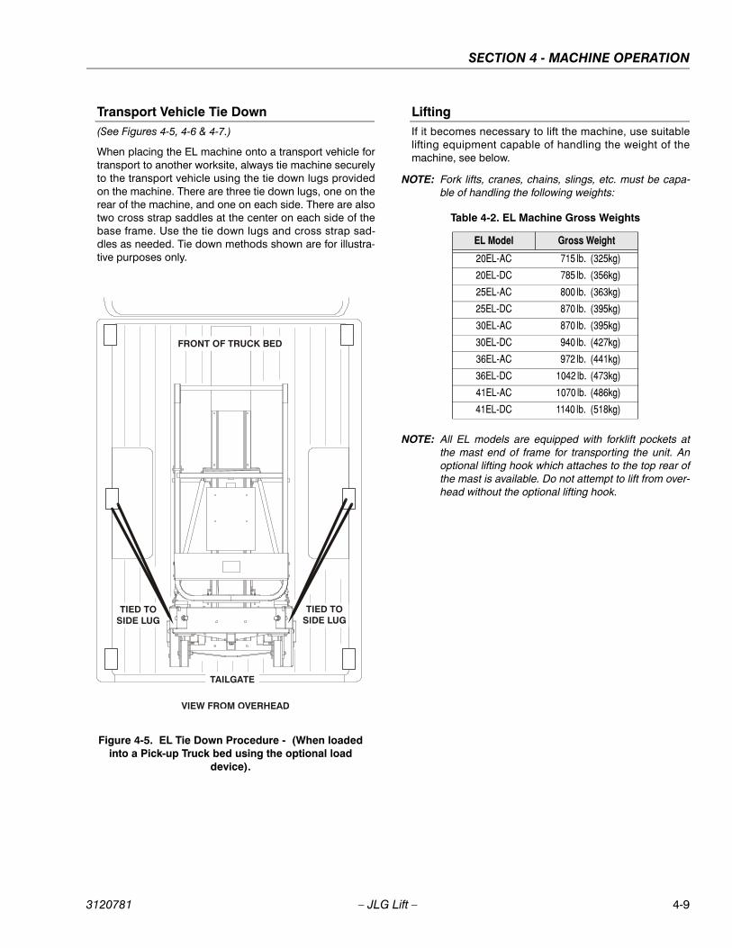
SECTION 4 - MACHINE OPERATION
Transport Vehicle Tie Down(See Figures 4-5, 4-6 & 4-7.)
When placing the EL machine onto a transport vehicle fortransport to another worksite, always tie machine securelyto the transport vehicle using the tie down lugs providedon the machine. There are three tie down lugs, one on therear of the machine, and one on each side. There are alsotwo cross strap saddles at the center on each side of thebase frame. Use the tie down lugs and cross strap sad-dles as needed. Tie down methods shown are for illustra-tive purposes only.
LiftingIf it becomes necessary to lift the machine, use suitablelifting equipment capable of handling the weight of themachine, see below.
NOTE: Fork lifts, cranes, chains, slings, etc. must be capa-ble of handling the following weights:
NOTE: All EL models are equipped with forklift pockets atthe mast end of frame for transporting the unit. Anoptional lifting hook which attaches to the top rear ofthe mast is available. Do not attempt to lift from over-head without the optional lifting hook.
Figure 4-5. EL Tie Down Procedure - (When loaded into a Pick-up Truck bed using the optional load
device).
FRONT OF TRUCK BED
TAILGATE
VIEW FROM OVERHEAD
TIED TOSIDE LUG
TIED TOSIDE LUG
Table 4-2. EL Machine Gross Weights
EL Model Gross Weight
20EL-AC 715 lb. (325kg)
20EL-DC 785 lb. (356kg)
25EL-AC 800 lb. (363kg)
25EL-DC 870 lb. (395kg)
30EL-AC 870 lb. (395kg)
30EL-DC 940 lb. (427kg)
36EL-AC 972 lb. (441kg)
36EL-DC 1042 lb. (473kg)
41EL-AC 1070 lb. (486kg)
41EL-DC 1140 lb. (518kg)
3120781 – JLG Lift – 4-9
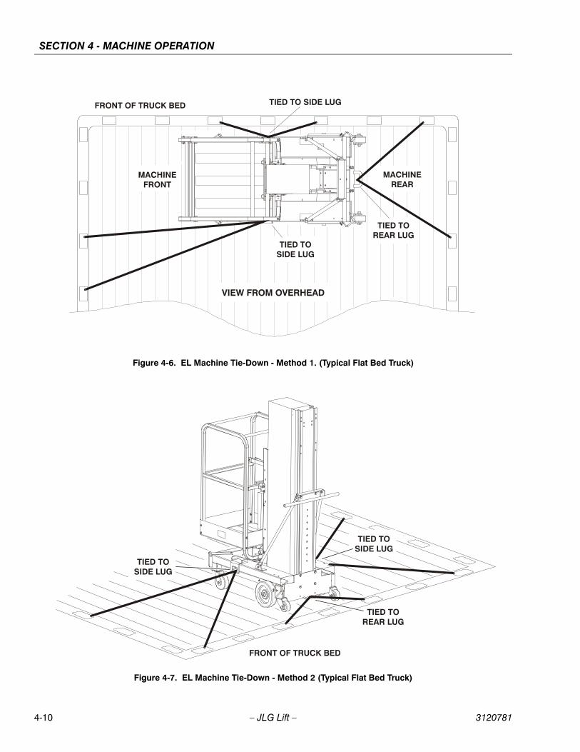
SECTION 4 - MACHINE OPERATION
Figure 4-6. EL Machine Tie-Down - Method 1. (Typical Flat Bed Truck)
TIED TOREAR LUG
FRONT OF TRUCK BED
TIED TOSIDE LUG
VIEW FROM OVERHEAD
TIED TO SIDE LUG
MACHINEFRONT
MACHINEREAR
Figure 4-7. EL Machine Tie-Down - Method 2 (Typical Flat Bed Truck)
FRONT OF TRUCK BED
TIED TOSIDE LUG
TIED TOSIDE LUG
TIED TOREAR LUG
4-10 – JLG Lift – 3120781
SECTION 5 - OPTIONAL EQUIPMENT
SECTION 5. OPTIONAL EQUIPMENT
5.1 OPTIONAL EQUIPMENTThe EL Series machines are available with the followingoptional equipment:
22" x 25" Quick-Change PlatformThe 25" long by 22" wide platform features a gull winggate opening and is attached to the mast using the quick-change mount.
26" x 26" Quick-Change PlatformThe 26" long by 26" wide platform features a side entrygate opening and is attached to the mast using the quick-change mount.
28" x 26" Quick-Change PlatformThe 28" long by 22" wide platform features a gull winggate opening and is attached to the mast using the quick-change mount.
25" x 26" Step-in Molded Platformw/Swing-up GateThe 25" long by 26" wide Step-in Molded Platform featuresa tough molded shell base and sides mounted to awelded steel frame. This step-in platform features a swing-up gate for easy entry.
Tool TrayThe tool tray is attached to the top rail of the platformallowing for quick access to hand tools or other smallitems placed in the tray.
Fluorescent Tube CaddyThe fluorescent tube caddy is attached to the top rail ofthe platform allowing for convenient handling whenreplacing fluorescent tubes.
Lifting HookThe optional lifting hook is mounted at the top rear of thefirst mast section. The hook is used to lift the machine upor down to another level.
Straddle Extension Kit (Requires Straddle Adapter)
(See Section 5.2 for Installation and Use instructions)
The AM-SE Straddle Extension Kit attaches to the AMmachine allowing a user to lift the machine and move itover obstacles up to four feet in height. This allows themachine access to areas above the obstacle.
Ladder for Straddle ExtensionThis is the ladder for the AM-SE Straddle Extension Kitwhich allows the user access to the AM/EL machine onceit is raised using the Straddle Kit.
Extra Power Pack (Battery, Charger & Case)
An extra power pack which includes the battery, chargerand molded case allows for extended use of an ELmachine under high cycle conditions. One power packcan be charging while the other is in use.
Platform Auxiliary Power Lowering DeviceThe Platform Auxiliary Power Lowering device is a switchactivated battery backed electrical circuit designed to pro-vide power to the platform control box in the event of lossof the machines power supply. This can be useful to theoperator if the main battery on a DC model becomesdepleted or the AC power supply of an AC model is inter-rupted while the platform is raised. Also if the on/off keyswitch on the ground control station is turned to the offposition while the platform is still raised.
Laser Positioning DeviceThe laser positioning device attaches to the platform rail-ing and when powered on projects a laser dot on any sur-face above the machine. This allows the operator to moreaccurately position the machine under a work area beforeraising the platform in position.
3120781 – JLG Lift – 5-1
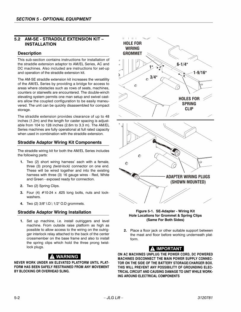
SECTION 5 - OPTIONAL EQUIPMENT
5.2 AM-SE - STRADDLE EXTENSION KIT – INSTALLATION
DescriptionThis sub-section contains instructions for installation ofthe straddle extension adaptor to AM/EL Series, AC andDC machines. Also included are instructions for set-upand operation of the straddle extension kit.
The AM-SE straddle extension kit increases the versatilityof the AM/EL Series by providing a bridge for access toareas where obstacles such as rows of seats, machines,counters or stairwells are encountered. The double-winchelevating system permits one man setup and swivel cast-ers allow the coupled configuration to be easily maneu-vered. The unit can be quickly disassembled for compactstorage.
The straddle extension provides clearance of up to 48inches (1.2m) and the length for caster spacing is adjust-able from 104 to 128 inches (2.6m to 3.3 m). The AM/ELSeries machines are fully operational at full rated capacitywhen used in combination with the straddle extension.
Straddle Adaptor Wiring Kit Components
The straddle wiring kit for both the AM/EL Series includesthe following parts:
1. Two (2) short wiring harness’ each with a female,three (3) prong (twist-lock) connector on one end.These will be wired together and into the existingharness with three (3) 16 gauge wires - Red, Whiteand Green - exposed ready for connection.
2. Two (2) Spring Clips.
3. Four (4) #10-24 x .625 long bolts, nuts and lock-washers.
4. Two (2) 3/8" I.D.\ 1/2" O.D grommets.
Straddle Adaptor Wiring Installation
1. Set up machine, i.e. install outriggers and levelmachine. From outside raise platform as high aspossible to allow access to the wiring on the outrig-ger interlock relay attached to the back of the centercrossmember on the base frame and also to installthe spring clips which hold the three prong twist-lock plugs.
NEVER WORK UNDER AN ELEVATED PLATFORM UNTIL PLAT-FORM HAS BEEN SAFELY RESTRAINED FROM ANY MOVEMENTBY BLOCKING OR OVERHEAD SLING.
2. Place a floor jack or other suitable support betweenthe mast and floor before working underneath plat-form.
ON AC MACHINES UNPLUG THE POWER CORD, DC POWEREDMACHINES DISCONNECT THE MAIN POWER SUPPLY CONNEC-TOR ON THE SIDE OF THE BATTERY STORAGE/CHARGER BOX.THIS WILL PREVENT ANY POSSIBILITY OF GROUNDING ELEC-TRICAL CIRCUIT AND CAUSING DAMAGE TO UNIT WHILE WORK-ING AROUND ELECTRICAL COMPONENTS
Figure 5-1. SE-Adapter - Wiring KitHole Locations for Grommet & Spring Clips
(Same For Both Sides)
1"
3/4"
6-1/4"
HOLE FORWIRING
GROMMET
HOLES FORSPRING
CLIP
1-9/16"
ADAPTER WIRING PLUGS(SHOWN MOUNTED)
5-2 – JLG Lift – 3120781
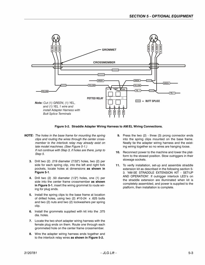
SECTION 5 - OPTIONAL EQUIPMENT
NOTE: The holes in the base frame for mounting the springclips and routing the wires through the center cross-member to the interlock relay may already exist onlate model machines. (See Figure 5-1.)If not continue with Step 3, if holes are there, jump toStep 5.
3. Drill two (2) .219 diameter (7/32") holes, two (2) perside for each spring clip, into the left and right forkpockets, locate holes at dimensions as shown inFigure 5-1.
4. Drill two (2) .50 diameter (1/2") holes, one (1) perside into the center frame crossmember as shownin Figure 5-1, insert the wiring grommet to route wir-ing for plug ends.
5. Install the spring clips to the base frame at locationof drilled holes, using two (2) #10-24 x .625 boltsand two (2) nuts and two (2) lockwashers per springclip.
6. Install the grommets supplied with kit into the .375dia. holes.
7. Locate the two short adapter wiring harness with thefemale plug ends on them. Route one through eachgrommeted hole on the center frame crossmember.
8. Wire the adapter wiring harness ends together andto the interlock relay wires as shown in Figure 5-2.
9. Press the two (2) - three (3) prong connector endsinto the spring clips mounted on the base frame.Neatly tie the adapter wiring harness and the exist-ing wiring together so no wires are hanging loose.
10. Reconnect power to the machine and lower the plat-form to the stowed position. Stow outriggers in theirstowage sockets.
11. To verify installation, set-up and assemble straddleextension kit as described in the following section 5-3. "AM-SE STRADDLE EXTENSION KIT - SET-UPAND OPERATION". If outrigger interlock LED’s onthe straddle extension are illuminated when kit iscompletely assembled, and power is supplied to theplatform, then installation is complete.
Figure 5-2. Straddle Adapter Wiring Harness to AM/EL Wiring Connections.
CROSSMEMBER
GROMMET
POTTED RELAY= BUTT SPLICE
G SG S
RED 16
YEL 1YEL 1
WHITE 16
GREEN
YELLOWYELLOW
YELLOW
GREEN 16
GREEN
BLACK
BLU
BLU
BLU
BLUGREEN
GREENGREEN
BLACK
OUTPUTB+ GRND.
1342
Note: Cut (1) GREEN, (1) YEL, and (1) YEL 1 wire and install Adapter Harness with Butt Splice Terminals
++
3120781 – JLG Lift – 5-3
SECTION 5 - OPTIONAL EQUIPMENT
5.3 AM-SE - STRADDLE EXTENSION KIT – SET-UP AND OPERATION
Straddle Extension - ComponentsThe AM-SE Straddle Extension kit can be set up by oneperson without tools. The AM-SE kit consists of eight (8)structural components. Those eight (8) components are:
1. Two (2) extendable side lifting rails.
2. Two (2) end straddle supports on locking swivelcaster wheels, each with (hand cranked) lifting winchand winch cables, outrigger interlock - retractablecable reel and quick-release safety pins.
3. Four (4) short outrigger (pup) beams which intercon-nect the straddle extension side lifting rails with theAM/EL base outrigger sockets.
Mounting - Straddle Ext. to AM/EL Machine(See Figure 5-3.)
1. Near work area find a suitable area large enough toassemble the AM/EL machine to the Straddle Exten-sion Kit. Assembly area should be a smooth, firm,level surface on which the assembled straddleextension and AM/EL machine can be easilymaneuvered.
2. Locate both extendable side lifting rails and the four(4) (pup) outrigger beams.
3. Start with either side and install one (1) of the (pup)outrigger beams into an outrigger socket in the AM/EL base. Push it in until the locking pin secures the(pup) beam in place.
4. Next pick-up one (1) of the side lifting rails (positionwith the outrigger sockets on the bottom), align the(pup) outrigger beam installed in previous step withthe appropriate side lifting rail outrigger socket andslide the side lifting rail onto the (pup) outriggerbeam.
5. On the same side lifting rail install the remaining(pup) outrigger beam into the side lifting rail socketand align with the AM/EL base outrigger socket.Push (pup) beam in until the locking pin in the AM/EL base secures the (pup) beam in place.
6. Mount the remaining side lifting rail by repeating theinstructions in steps 4 and 5.
7. Next locate either end straddle support, (mount endstraddle support with the winch handle positioned tooutside), align the two vertical rails of the end strad-dle support with the adjust bracket opening on endsof lifting rails.
NOTE: Lock the castor wheels on the bottom of the endstraddle supports so they are parallel with the outrig-ger sockets. This will help to keep the end straddlesupport stable during assembly.
8. Insert vertical rails into the adjust brackets (inagainst the slide pads), and insert an adjust bracketend cap (with slide pad against vertical rail) into theslot on the adjust brackets on both side rails.
9. Secure end caps with the quick-release pin wired tothe end cap, install pin into hole in adjust bracketjust above end cap. (See Figure 5-3. and 5-4.)
10. Repeat steps seven, eight and nine to mount otherend straddle support.
11. At both end straddle supports, attach the winchcable clevis ends to the lifting lugs (on the side liftingrail - adjust brackets), using the quick-release pinsattached to winch cables.
12. Turn winch handle clockwise just enough to start lift-ing side rails. Observe winch cables, both cablesmust be lifting evenly.
If not lifting evenly, adjust slack out of long cableusing the following steps:
a. Lower side rails by turning winch handlescounter-clockwise enough to remove any ten-sion on the winch cables.
b. Remove the quick-release pin securing thewinch cable clevis to the lifting lug on the siderail adjust bracket.
c. Loosen the jam nut on the threaded cable endand turn the clevis end clockwise to shorten thecable.
d. Before tightening the jam nut re-install the winchcable to the side rail lifting lug with the quickrelease pin.
e. Turn winch handle to start lifting side rails, againobserve winch cables. If cables are lifting evenly,retighten jam nut on threaded end of winchcable. If not lifting evenly repeat steps (a)through (e) until properly adjusted.
13. Connect the outrigger interlock cable ends (male)from the retractable reels (mounted on both endstraddle supports) to the connector ends (female)mounted on the AM/EL base frame under the plat-form.
Positioning Straddle Unit and Lifting AM/EL Machine
WHEN EXTENDING SIDE LIFTING RAILS, DO NOT EXTEND RAILSINTO THE RED ZONE PAINTED ON THE RAILS.
5-4 – JLG Lift – 3120781
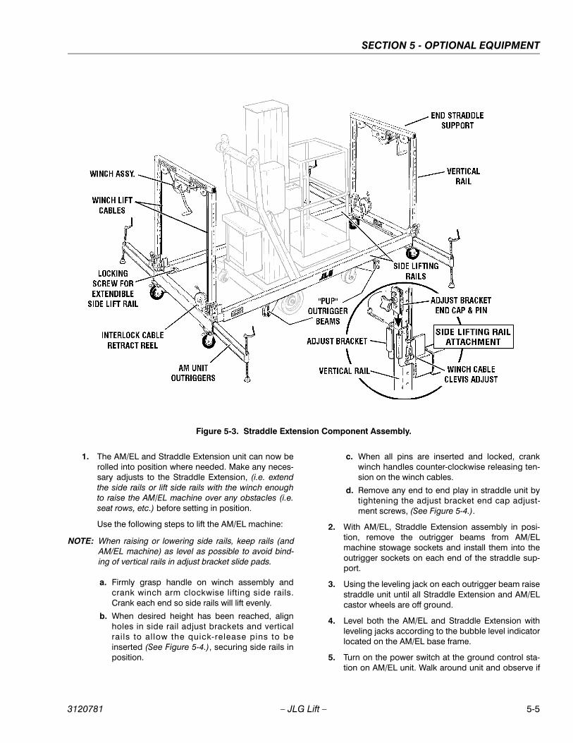
SECTION 5 - OPTIONAL EQUIPMENT
1. The AM/EL and Straddle Extension unit can now berolled into position where needed. Make any neces-sary adjusts to the Straddle Extension, (i.e. extendthe side rails or lift side rails with the winch enoughto raise the AM/EL machine over any obstacles (i.e.seat rows, etc.) before setting in position.
Use the following steps to lift the AM/EL machine:
NOTE: When raising or lowering side rails, keep rails (andAM/EL machine) as level as possible to avoid bind-ing of vertical rails in adjust bracket slide pads.
a. Firmly grasp handle on winch assembly andcrank winch arm clockwise lifting side rails.Crank each end so side rails will lift evenly.
b. When desired height has been reached, alignholes in side rail adjust brackets and verticalrails to allow the quick-release pins to beinserted (See Figure 5-4.), securing side rails inposition.
c. When all pins are inserted and locked, crankwinch handles counter-clockwise releasing ten-sion on the winch cables.
d. Remove any end to end play in straddle unit bytightening the adjust bracket end cap adjust-ment screws, (See Figure 5-4.).
2. With AM/EL, Straddle Extension assembly in posi-tion, remove the outrigger beams from AM/ELmachine stowage sockets and install them into theoutrigger sockets on each end of the straddle sup-port.
3. Using the leveling jack on each outrigger beam raisestraddle unit until all Straddle Extension and AM/ELcastor wheels are off ground.
4. Level both the AM/EL and Straddle Extension withleveling jacks according to the bubble level indicatorlocated on the AM/EL base frame.
5. Turn on the power switch at the ground control sta-tion on AM/EL unit. Walk around unit and observe if
Figure 5-3. Straddle Extension Component Assembly.
3120781 – JLG Lift – 5-5
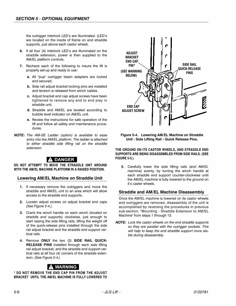
SECTION 5 - OPTIONAL EQUIPMENT
the outrigger interlock LED’s are illuminated. (LED’sare located on the inside of frame on end straddlesupports, just above each castor wheel).
6. If all four (4) interlock LED’s are illuminated on thestraddle extension, power is then supplied to theAM/EL platform controls.
7. Recheck each of the following to insure the lift isproperly set-up and ready to use:
a. All "pup" outrigger beam adapters are lockedand secured.
b. Side rail adjust bracket locking pins are installedand tension is released from winch cables.
c. Adjust bracket end cap adjust screws have beentightened to remove any end to end play instraddle unit.
d. Straddle and AM/EL are leveled according tobubble level indicator on AM/EL unit.
e. Review the instructions for safe operation of thelift and follow all safety and maintenance proce-dures.
NOTE: The AM-SE Ladder (option) is available to easeentry into the AM/EL platform. The ladder is attachedto either straddle side lifting rail on the straddleextension.
DO NOT ATTEMPT TO MOVE THE STRADDLE UNIT AROUNDWITH THE AM/EL MACHINE PLATFORM IN A RAISED POSITION.
Lowering AM/EL Machine on Straddle Unit
1. If necessary remove the outriggers and move thestraddle and AM/EL unit to an area which will allowaccess to the straddle end supports.
2. Loosen adjust screws on adjust bracket end caps(See Figure 5-4.).
3. Crank the winch handle on each winch (located onstraddle end supports) clockwise, just enough tostart raising the side lifting rails, lifting the weight offof the quick-release pins installed through the siderail adjust bracket and the straddle end support ver-tical rails.
4. Remove ONLY the two (2) SIDE RAIL QUICK-RELEASE PINS installed through each side liftingrail adjust bracket, and the straddle end support ver-tical rails at all four (4) corners of the straddle exten-sion. (See Figure 5-4.)
* DO NOT REMOVE THE END CAP PIN FROM THE ADJUSTBRACKET UNTIL THE AM/EL MACHINE IS FULLY LOWERED TO
THE GROUND ON ITS CASTOR WHEELS, AND STRADDLE ENDSUPPORTS ARE BEING DISASSEMBLED FROM SIDE RAILS. (SEEFIGURE 5-5.)
5. Carefully lower the side lifting rails (and AM/ELmachine) evenly, by turning the winch handle ateach straddle end support counter-clockwise untilthe AM/EL machine is fully lowered to the ground onit’s caster wheels.
Straddle and AM/EL Machine DisassemblyOnce the AM/EL machine is lowered on its castor wheelsand outriggers are removed, disassembly of the unit isaccomplished by reversing the procedures in previoussub-section, "Mounting - Straddle Extension to AM/ELMachine" from steps 1 through 13.
NOTE: Lock the castor wheels on the end straddle supportsso they are parallel with the outrigger sockets. Thiswill help to keep the end straddle support more sta-ble during disassembly.
Figure 5-4. Lowering AM/EL Machine on Straddle Unit - Side Lifting Rail - Quick Release Pins.
SIDE RAILQUICK-RELEASE
PINS
ADJUSTBRACKETEND CAP
PIN*
(SEE WARNINGBELOW)
END CAPADJUST SCREW
5-6 – JLG Lift – 3120781
SECTION 6 - EMERGENCY PROCEDURES
SECTION 6. EMERGENCY PROCEDURES
6.1 GENERAL INFORMATION This section provides information on procedures to be fol-lowed, and systems and controls to be used in the eventan emergency situation is encountered during machineoperation. Prior to operation of the machine and periodi-cally thereafter, the entire operating manual, including thissection, should be reviewed by all personnel whoseresponsibilities include any work or contact with themachine.
6.2 EMERGENCY CONTROLS AND THEIRLOCATIONS
CHECK MACHINE DAILY TO MAKE SURE EMERGENCY STOPSWITCHES ARE IN PLACE AND OPERATIONAL. AND THATAPPLICABLE INSTRUCTIONS ARE IN PLACE AND LEGIBLE.
Platform Emergency Stop SwitchThis large red button is located on the platform controlstation and, when depressed, will immediately stop themachine from the platform.
Ground Emergency Stop SwitchThe ground Emergency Stop switch (RED button) islocated on the Ground Control Station beside the PowerOn/OFF Key switch. When depressed, will immediatelystop the machine.
Manual Descent Valve KnobThe manual descent valve is used in the event of either atotal power failure, or if the operator in the platform cannotlower the platform himself. The manual descent knob(RED) is located under the base frame at the rear of themachine. To LOWER the platform, PULL the RED knob(valve open). To STOP lowering, RELEASE the knob(valve closed). (The platform will be lowered, unpowered,using gravity.)
6.3 EMERGENCY OPERATION
Use of Ground Controls.
KNOW HOW TO USE THE GROUND CONTROLS IN AN EMER-GENCY SITUATION.
BEFORE TOUCHING ANY PART OF THE MACHINE IN AN EMER-GENCY SITUATION, FIRST DETERMINE IF MACHINE IS IN CON-TACT WITH OR CLOSE PROXIMITY TO AN ELECTRICALLYCHARGED CONDUCTOR. THIS MACHINE DOES NOT PROVIDEPROTECTION FROM CONTACT WITH OR PROXIMITY TO ANELECTRICALLY CHARGED CONDUCTOR. (SEE ELECTROCUTIONHAZARD, SECTION 1-3.)
Ground personnel must be thoroughly familiar with themachine operating characteristics and the ground controlfunctions. Training should include operation of themachine, review and understanding of this section andhands-on operation of the controls in simulated emergen-cies.
Operator Unable to Control Machine
IF THE PLATFORM OPERATOR IS PINNED, TRAPPED OR UNABLETO OPERATE OR CONTROL THE MACHINE, USE THE FOLLOW-ING INSTRUCTIONS AS A GUIDELINE.
1. Operate the machine from the ground controlsONLY with the assistance of other personnel andequipment (cranes, overhead hoists, etc.) as may berequired to safely remove the danger or emergencycondition.
2. Only qualified personnel in the platform may use theplatform controls. [DO NOT CONTINUE OPERA-TION IF CONTROLS DO NOT FUNCTION NOR-MALLY].
3. Cranes, forklift trucks or other equipment which maybe available are to be used to help remove the plat-form occupant and stabilize motion of the machinein case machine controls are inoperable or platformcannot be lowered with the emergency/manualdecent valve.
(continued next page)
3120781 – JLG Lift – 6-1
SECTION 6 - EMERGENCY PROCEDURES
Platform Caught OverheadIf the platform becomes jammed or snagged in overheadstructures or equipment, do not continue operation of themachine from either the platform or the ground until theoperator and all personnel are safely moved to a securelocation. Only then should an attempt be made to free theplatform using any necessary equipment and personnel.Do not remove outriggers or attempt to move machineunless a crane, forklift or other suitable equipment is avail-able to safely lower machine to ground.
Righting of Tipped MachineBefore righting a tipped machine, check machine for anydamage which may prevent it from setting properly on itsbase wheels once in a vertical position, (i.e. base wheelsdamaged, base frame distorted, etc.). Use a crane, forkliftor other suitable lifting equipment and carefully lift themachine to an upright postion.
Post-Incident InspectionFollowing any incident, thoroughly inspect the machineand test all functions. Do not lift platform above 10 feet (3meters) until you are sure that all damage has beenrepaired and that all controls and machine componentsare operating correctly.
6.4 INCIDENT NOTIFICATIONIt is imperative that JLG Industries, Inc. be notified imme-diately of any incident involving a JLG product. Even if noinjury or property damage is evident, the Product Safetyand Reliability Department at the factory should be con-tacted by telephone and provided with all necessarydetails.
JLG Phone: 877-JLG-SAFE (554-7233) (8am till 4:45pm EST)
Email: [email protected]
It should be noted that failure to notify the Manufacturer ofan incident involving a JLG Industries product within 48hours of such an occurrence may void any warranty con-sideration on that particular machine.
6-2 – JLG Lift – 3120781

SECTION 7 - INSPECTION AND REPAIR LOG
SECTION 7. INSPECTION AND REPAIR LOG
Table 7-1. Inspection and Repair Log
Date Comments
Machine Serial Number:
3120781 – JLG Lift – 7-1

SECTION 7 - INSPECTION AND REPAIR LOG
Table 7-1. Inspection and Repair Log
Date Comments
7-2 – JLG Lift – 3120781
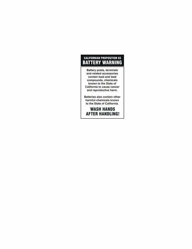
JLG Worldwide Locations
Corporate Office
JLG Industries, Inc.
1 JLG Drive
McConnellsburg PA. 17233-9533
USA
Phone: (717) 485-5161
Fax: (717) 485-6417
JLG Industries (Australia)P.O. Box 511911 Bolwarra RoadPort MacquarieN.S.W. 2444AustraliaPhone: (61) 2 65 811111Fax: (61) 2 65 810122
JLG Industries (UK)Unit 12, SouthsideBredbury Park Industrial EstateBredburyStockportSK6 2sPEnglandPhone: (44) 870 200 7700Fax: (44) 870 200 7711
JLG Deutschland GmbHMax Planck Strasse 21D-27721 Ritterhude/lhlpohlBei BremenGermanyPhone: (49) 421 693 500Fax: (49) 421 693 5035
JLG Industries (Italia)Via Po. 2220010 Pregnana Milanese - MIItalyPhone: (39) 02 9359 5210Fax: (39) 02 9359 5845
JLG Latino Americana Ltda.Rua Eng. Carlos Stevenson,80-Suite 7113092-310 Campinas-SPBrazilPhone: (55) 19 3295 0407Fax: (55) 19 3295 1025
JLG Europe B.V.Jupiterstraat 2342132 HJ FoofddorpThe NetherlandsPhone: (31) 23 565 5665Fax: (31) 23 557 2493
JLG Industries (Norge AS)Sofeimyrveien 12N-1412 SofienyrNorwayPhone: (47) 6682 2000Fax: (47) 6682 2001
JLG PolskaUI. Krolewska00-060 WarsawaPolandPhone: (48) 91 4320 245Fax: (48) 91 4358 200
JLG Industries (Europe)Kilmartin Place, Tannochside ParkUddingston G71 5PHScotlandPhone: (44) 1 698 811005Fax: (44) 1 698 811055
JLG Industries (Pty) Ltd.Unit 1, 24 Industrial ComplexHerman StreetMeadowdaleGermistonSouth AfricaPhone: (27) 11 453 1334Fax: (27) 11 453 1342
Plataformas Elevadoras JLG Iberica, S.L.Trapadella, 2P.I. Castellbisbal Sur08755CastellbisbalSpainPhone: (34) 93 77 24700Fax: (34) 93 77 11762
JLG Industries (Sweden)Enkopingsvagen 150Box 704SE - 175 27 JarfallaSwedenPhone: (46) 8 506 59500Fax: (46) 8 506 59534