Embed Size (px)
Citation preview
Operation and Safety Manual
ANSI ®
Original Instructions - Keep this manual with the machine at all times.
Boom Lift ModelsE300AJE300AJPS/N 0300138358 to Present
3121252January 5, 2015

FOREWORD
a
s.
rs, and lessees with the precautions and operatingtended purpose.
the right to make specification changes without
3121252 – JLG Lift –
FOREWORD
This manual is a very important tool! Keep it with the machine at all time
The purpose of this manual is to provide owners, users, operators, lessoprocedures essential for the safe and proper machine operation for its in
Due to continuous product improvements, JLG Industries, Inc. reservesprior notification. Contact JLG Industries, Inc. for updated information.
FOREWORD
b 3121252
SIGNAL WORDS
INDIRESUGROU
INDIRESUGROU
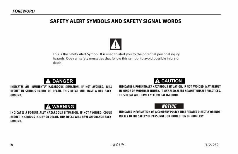
TIALLY HAZARDOUS SITUATION. IF NOT AVOIDED, MAY RESULTRATE INJURY. IT MAY ALSO ALERT AGAINST UNSAFE PRACTICES.
AVE A YELLOW BACKGROUND.
ATION OR A COMPANY POLICY THAT RELATES DIRECTLY OR INDI-ETY OF PERSONNEL OR PROTECTION OF PROPERTY.
potential personal injury avoid possible injury or
– JLG Lift –
SAFETY ALERT SYMBOLS AND SAFETY
CATES AN IMMINENTLY HAZARDOUS SITUATION. IF NOT AVOIDED, WILLLT IN SERIOUS INJURY OR DEATH. THIS DECAL WILL HAVE A RED BACK-ND.
CATES A POTENTIALLY HAZARDOUS SITUATION. IF NOT AVOIDED, COULDLT IN SERIOUS INJURY OR DEATH. THIS DECAL WILL HAVE AN ORANGE BACK-ND.
INDICATES A POTENIN MINOR OR MODETHIS DECAL WILL H
INDICATES INFORMRECTLY TO THE SAF
This is the Safety Alert Symbol. It is used to alert you to the hazards. Obey all safety messages that follow this symbol todeath
FOREWORD
c
ct:uct Safety and Reliability Department
Industries, Inc.4 Fountainhead Plaza
erstown, MD 21742
ur Local JLG Office addresses on inside of manual cover)
A:
Free: 877-JLG-SAFE (877-554-7233)
de USA:e: 240-420-2661
301-745-3713il: [email protected]
ent Reporting
ct Safety Publica-
nt Owner Updates
ions Regarding ct Safety
• Standards and Regulations Compliance Information
• Questions Regarding Special Product Applications
• Questions Regarding Prod-uct Modifications
3121252 – JLG Lift –
THIS PRODUCT MUST COMPLY WITH ALL SAFETY RELATED BULLETINS. CONTACT JLGINDUSTRIES, INC. OR THE LOCAL AUTHORIZED JLG REPRESENTATIVE FOR INFORMA-TION REGARDING SAFETY-RELATED BULLETINS WHICH MAY HAVE BEEN ISSUED FORTHIS PRODUCT.
JLG INDUSTRIES, INC. SENDS SAFETY RELATED BULLETINS TO THE OWNER OFRECORD OF THIS MACHINE. CONTACT JLG INDUSTRIES, INC. TO ENSURE THAT THECURRENT OWNER RECORDS ARE UPDATED AND ACCURATE.
JLG INDUSTRIES, INC. MUST BE NOTIFIED IMMEDIATELY IN ALL INSTANCES WHEREJLG PRODUCTS HAVE BEEN INVOLVED IN AN ACCIDENT INVOLVING BODILY INJURYOR DEATH OF PERSONNEL OR WHEN SUBSTANTIAL DAMAGE HAS OCCURRED TO PER-SONAL PROPERTY OR THE JLG PRODUCT.
ContaProdJLG 1322HagUSA
or Yo(See
In US
Toll
OutsiPhonFax: E-ma
For:• Accid
• Produtions
• Curre
• QuestProdu
FOREWORD
d 3121252
O
Re
Re
Re
Re
Re
Re
Re
– JLG Lift –
REVISION LOG
riginal Issue - June 26, 2009
vised - September 29, 2009
vised - October 28, 2009
vised - November 19, 2009
vised - November 8, 2010
vised - February 6, 2012
vised - August 9, 2012
vised - January 5, 2015
312 i
SEC PARAGRAPH, SUBJECT PAGE
TABLE OF CONTENTS
SEC
SECA
SkyGuard Function Test. . . . . . . . . . . . . . . . . . . . . . . . . . . . 2-6General . . . . . . . . . . . . . . . . . . . . . . . . . . . . . . . . . . . . . . . . . . . 2-9
- MACHINE CONTROLS AND INDICATORS
GENERAL . . . . . . . . . . . . . . . . . . . . . . . . . . . . . . . . . . . . . . . . . . . . 3-1CONTROLS AND INDICATORS . . . . . . . . . . . . . . . . . . . . . . . . 3-1
Ground Control Station . . . . . . . . . . . . . . . . . . . . . . . . . . . . 3-2Platform Station . . . . . . . . . . . . . . . . . . . . . . . . . . . . . . . . . . . 3-9Platform Control Indicator Panel . . . . . . . . . . . . . . . . . 3-13
- MACHINE OPERATION
DESCRIPTION . . . . . . . . . . . . . . . . . . . . . . . . . . . . . . . . . . . . . . . . 4-1BOOM OPERATING CHARACTERISTICS AND LIMITATIONS . . . . . . . . . . . . . . . . . . . . . . . . . . . . . . . . . . . . . . . . 4-2
Capacities . . . . . . . . . . . . . . . . . . . . . . . . . . . . . . . . . . . . . . . . . 4-2Stability . . . . . . . . . . . . . . . . . . . . . . . . . . . . . . . . . . . . . . . . . . . 4-2
MOTOR OPERATION. . . . . . . . . . . . . . . . . . . . . . . . . . . . . . . . . . 4-6Power/Emergency Stop Switch . . . . . . . . . . . . . . . . . . . . 4-6Platform/Ground Select Switch . . . . . . . . . . . . . . . . . . . . 4-6Motor Activation . . . . . . . . . . . . . . . . . . . . . . . . . . . . . . . . . . 4-6
TRAVELING (DRIVING) . . . . . . . . . . . . . . . . . . . . . . . . . . . . . . . . 4-7Traveling Forward and Reverse . . . . . . . . . . . . . . . . . . . . 4-9
STEERING . . . . . . . . . . . . . . . . . . . . . . . . . . . . . . . . . . . . . . . . . . . . 4-9PLATFORM . . . . . . . . . . . . . . . . . . . . . . . . . . . . . . . . . . . . . . . . . . 4-9
Platform Level Adjustment. . . . . . . . . . . . . . . . . . . . . . . . . 4-9Platform Rotation. . . . . . . . . . . . . . . . . . . . . . . . . . . . . . . . . . 4-9
1252 – JLG Lift –
TION - PARAGRAPH, SUBJECT PAGE SECTION -TION - 1 - SAFETY PRECAUTIONS
1.1 GENERAL . . . . . . . . . . . . . . . . . . . . . . . . . . . . . . . . . . . . . . . . . . . . 1-11.2 PRE-OPERATION . . . . . . . . . . . . . . . . . . . . . . . . . . . . . . . . . . . . . 1-1
Operator Training and Knowledge . . . . . . . . . . . . . . . . . 1-1Workplace Inspection. . . . . . . . . . . . . . . . . . . . . . . . . . . . . . 1-2Machine Inspection. . . . . . . . . . . . . . . . . . . . . . . . . . . . . . . . 1-3
1.3 OPERATION . . . . . . . . . . . . . . . . . . . . . . . . . . . . . . . . . . . . . . . . . . 1-3General . . . . . . . . . . . . . . . . . . . . . . . . . . . . . . . . . . . . . . . . . . . 1-3Trip and Fall Hazards. . . . . . . . . . . . . . . . . . . . . . . . . . . . . . . 1-4Electrocution Hazards . . . . . . . . . . . . . . . . . . . . . . . . . . . . . 1-5Tipping Hazards . . . . . . . . . . . . . . . . . . . . . . . . . . . . . . . . . . . 1-7Crushing and Collision Hazards . . . . . . . . . . . . . . . . . . 1-10
1.4 TOWING, LIFTING, AND HAULING . . . . . . . . . . . . . . . . . . . . 1-111.5 MAINTENANCE. . . . . . . . . . . . . . . . . . . . . . . . . . . . . . . . . . . . . . 1-11
Maintenance Hazards . . . . . . . . . . . . . . . . . . . . . . . . . . . . 1-11Battery Hazards. . . . . . . . . . . . . . . . . . . . . . . . . . . . . . . . . . 1-13
TION - 2 - USER RESPONSIBILITIES, MACHINE PREPARATION, ND INSPECTION
2.1 PERSONNEL TRAINING . . . . . . . . . . . . . . . . . . . . . . . . . . . . . . . 2-1Operator Training . . . . . . . . . . . . . . . . . . . . . . . . . . . . . . . . . 2-1Training Supervision . . . . . . . . . . . . . . . . . . . . . . . . . . . . . . . 2-1Operator Responsibility . . . . . . . . . . . . . . . . . . . . . . . . . . . . 2-1
2.2 PREPARATION, INSPECTION, AND MAINTENANCE . . . . . 2-2Pre-Start Inspection. . . . . . . . . . . . . . . . . . . . . . . . . . . . . . . . 2-4Function Check. . . . . . . . . . . . . . . . . . . . . . . . . . . . . . . . . . . . 2-5
SECTION - 3
3.13.2
SECTION - 4
4.14.2
4.3
4.4
4.54.6
ii 3121252
TABLE OF CONTENTS
SECTIO AGRAPH, SUBJECT PAGE4.7
4.84.9
4.14.14.1
SECTION
5.15.25.3
5.45.55.65.7
NERAL SPECIFICATIONS & OPERATOR E
ODUCTION. . . . . . . . . . . . . . . . . . . . . . . . . . . . . . . . . . . . . . 6-1RATING SPECIFICATIONS AND PERFORMANCE A . . . . . . . . . . . . . . . . . . . . . . . . . . . . . . . . . . . . . . . . . . . . . . . 6-1
perating Specifications . . . . . . . . . . . . . . . . . . . . . . . . . . 6-1imensional Data . . . . . . . . . . . . . . . . . . . . . . . . . . . . . . . . . 6-2pacities . . . . . . . . . . . . . . . . . . . . . . . . . . . . . . . . . . . . . . . . . 6-3
res . . . . . . . . . . . . . . . . . . . . . . . . . . . . . . . . . . . . . . . . . . . . . . 6-3draulic Oil . . . . . . . . . . . . . . . . . . . . . . . . . . . . . . . . . . . . . . 6-4
ajor Component Weights . . . . . . . . . . . . . . . . . . . . . . . . 6-7RATOR MAINTENANCE . . . . . . . . . . . . . . . . . . . . . . . . . . . 6-9
ERY MAINTENANCE AND CHARGING . . . . . . . . . . . 6-13ttery Maintenance, Quarterly . . . . . . . . . . . . . . . . . . . 6-13ttery Charging, Daily . . . . . . . . . . . . . . . . . . . . . . . . . . . 6-14
S & WHEELS . . . . . . . . . . . . . . . . . . . . . . . . . . . . . . . . . . . . 6-15re Replacement. . . . . . . . . . . . . . . . . . . . . . . . . . . . . . . . . 6-15heel and Tire Replacement . . . . . . . . . . . . . . . . . . . . . 6-15heel Installation . . . . . . . . . . . . . . . . . . . . . . . . . . . . . . . . 6-15PLEMENTAL INFORMATION . . . . . . . . . . . . . . . . . . . . . 6-16
SPECTION AND REPAIR LOG
– JLG Lift –
N - PARAGRAPH, SUBJECT PAGE SECTION - PARBOOM . . . . . . . . . . . . . . . . . . . . . . . . . . . . . . . . . . . . . . . . . . . . . . 4-10
Swinging the Boom . . . . . . . . . . . . . . . . . . . . . . . . . . . . . . 4-11Raising and Lowering the Upper Boom. . . . . . . . . . . . 4-11
FUNCTION SPEED CONTROL . . . . . . . . . . . . . . . . . . . . . . . . 4-11MACHINE SAFETY SYSTEM OVERRIDE (MSSO)(CE ONLY). . . . . . . . . . . . . . . . . . . . . . . . . . . . . . . . . . . . . . . . . . 4-12
0 SKYGUARD OPERATION . . . . . . . . . . . . . . . . . . . . . . . . . . . . . 4-121 SHUT DOWN AND PARK. . . . . . . . . . . . . . . . . . . . . . . . . . . . . 4-132 LIFTING AND TIE DOWN. . . . . . . . . . . . . . . . . . . . . . . . . . . . . 4-13
Lifting. . . . . . . . . . . . . . . . . . . . . . . . . . . . . . . . . . . . . . . . . . . . 4-13Tie Down. . . . . . . . . . . . . . . . . . . . . . . . . . . . . . . . . . . . . . . . . 4-14
- 5 - EMERGENCY PROCEDURES
GENERAL . . . . . . . . . . . . . . . . . . . . . . . . . . . . . . . . . . . . . . . . . . . . 5-1INCIDENT NOTIFICATION. . . . . . . . . . . . . . . . . . . . . . . . . . . . . 5-1EMERGENCY OPERATION. . . . . . . . . . . . . . . . . . . . . . . . . . . . . 5-1
Operator Unable to Control Machine. . . . . . . . . . . . . . . 5-1Platform or Boom Caught Overhead . . . . . . . . . . . . . . . 5-2
EMERGENCY TOWING PROCEDURES . . . . . . . . . . . . . . . . . . 5-2MANUAL DESCENT SYSTEM . . . . . . . . . . . . . . . . . . . . . . . . . . 5-2MANUAL SWING OVERRIDE . . . . . . . . . . . . . . . . . . . . . . . . . . 5-4MACHINE SAFETY SYSTEM OVERRIDE (MSSO)(CE ONLY). . . . . . . . . . . . . . . . . . . . . . . . . . . . . . . . . . . . . . . . . . . 5-4
SECTION - 6 - GEMAINTENANC
6.1 INTR6.2 OPE
DATODCaTiHyM
6.3 OPE6.4 BATT
BaBa
6.5 TIRETiWW
6.6 SUP
SECTION - 7 - IN
312 iii
LIST OF FIGURES
FIG MBER - TITLE PAGE
1252 – JLG Lift –
URE NUMBER - TITLE PAGE FIGURE NU2-1. Basic Nomenclature. . . . . . . . . . . . . . . . . . . . . . . . . . . . . . . . . . 2-72-2. Daily Walk-Around Inspection - Sheet 1 of 3 . . . . . . . . . . 2-82-3. Daily Walk-Around Inspection - Sheet 2 of 3 . . . . . . . . . . 2-92-4. Daily Walk-Around Inspection - Sheet 3 of 3 . . . . . . . . . 2-103-1. Ground Control Station - E300AJ . . . . . . . . . . . . . . . . . . . . . 3-33-2. Ground Control Station - E300AJ with Machine Safety
System Override (MSSO) (CE Only) . . . . . . . . . . . . . . . . . 3-43-3. Ground Control Station - E300AJP . . . . . . . . . . . . . . . . . . . . 3-53-4. Ground Control Station - E300AJP with Machine Safety
System Override (MSSO) (CE Only) . . . . . . . . . . . . . . . . . 3-63-5. Platform Control Console . . . . . . . . . . . . . . . . . . . . . . . . . . . 3-103-6. Platform Control Indicator Panel. . . . . . . . . . . . . . . . . . . . . 3-144-1. Position of Least Forward Stability . . . . . . . . . . . . . . . . . . . . 4-34-2. Position of Least Backward Stability - E300AJ . . . . . . . . . 4-44-3. Position of Least Backward Stability - E300AJP . . . . . . . . 4-54-4. Grade and Side Slopes . . . . . . . . . . . . . . . . . . . . . . . . . . . . . . . 4-84-5. Lifting and Tie Down Chart . . . . . . . . . . . . . . . . . . . . . . . . . . 4-154-6. Decal Location Sheet 1 of 5. . . . . . . . . . . . . . . . . . . . . . . . . . 4-164-7. Decal Location Sheet 2 of 5. . . . . . . . . . . . . . . . . . . . . . . . . . 4-174-8. Decal Location Sheet 3 of 5. . . . . . . . . . . . . . . . . . . . . . . . . . 4-184-9. Decal Location Sheet 4 of 5. . . . . . . . . . . . . . . . . . . . . . . . . . 4-194-10. Decal Location Sheet 5 of 5. . . . . . . . . . . . . . . . . . . . . . . . . . 4-205-1. Manual Descent Location . . . . . . . . . . . . . . . . . . . . . . . . . . . . 5-36-1. Operator Maintenance and Lubrication Diagram. . . . . . 6-8

iv 3121252
LIST O
FIGURE ER - TITLE PAGE
ally.
– JLG Lift –
F FIGURES
NUMBER - TITLE PAGE FIGURE NUMB
This Page Left Blank Intention
312 v
LIST OF TABLES
TAB MBER - TITLE PAGE
1252 – JLG Lift –
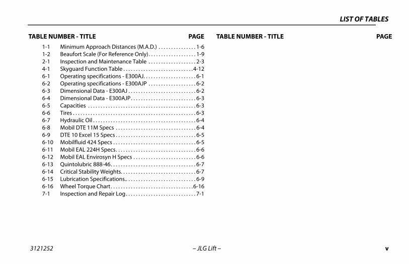
LE NUMBER - TITLE PAGE TABLE NU1-1 Minimum Approach Distances (M.A.D.) . . . . . . . . . . . . . . . 1-61-2 Beaufort Scale (For Reference Only). . . . . . . . . . . . . . . . . . . 1-92-1 Inspection and Maintenance Table . . . . . . . . . . . . . . . . . . . 2-34-1 Skyguard Function Table . . . . . . . . . . . . . . . . . . . . . . . . . . . .4-126-1 Operating specifications - E300AJ. . . . . . . . . . . . . . . . . . . . . 6-16-2 Operating specifications - E300AJP . . . . . . . . . . . . . . . . . . . 6-26-3 Dimensional Data - E300AJ . . . . . . . . . . . . . . . . . . . . . . . . . . . 6-26-4 Dimensional Data - E300AJP. . . . . . . . . . . . . . . . . . . . . . . . . . 6-36-5 Capacities . . . . . . . . . . . . . . . . . . . . . . . . . . . . . . . . . . . . . . . . . . . 6-36-6 Tires . . . . . . . . . . . . . . . . . . . . . . . . . . . . . . . . . . . . . . . . . . . . . . . . . 6-36-7 Hydraulic Oil . . . . . . . . . . . . . . . . . . . . . . . . . . . . . . . . . . . . . . . . . 6-46-8 Mobil DTE 11M Specs . . . . . . . . . . . . . . . . . . . . . . . . . . . . . . . . 6-46-9 DTE 10 Excel 15 Specs . . . . . . . . . . . . . . . . . . . . . . . . . . . . . . . . 6-56-10 Mobilfluid 424 Specs . . . . . . . . . . . . . . . . . . . . . . . . . . . . . . . . . 6-56-11 Mobil EAL 224H Specs. . . . . . . . . . . . . . . . . . . . . . . . . . . . . . . . 6-66-12 Mobil EAL Envirosyn H Specs . . . . . . . . . . . . . . . . . . . . . . . . . 6-66-13 Quintolubric 888-46. . . . . . . . . . . . . . . . . . . . . . . . . . . . . . . . . . 6-76-14 Critical Stability Weights. . . . . . . . . . . . . . . . . . . . . . . . . . . . . . 6-76-15 Lubrication Specifications.. . . . . . . . . . . . . . . . . . . . . . . . . . . . 6-96-16 Wheel Torque Chart . . . . . . . . . . . . . . . . . . . . . . . . . . . . . . . . .6-167-1 Inspection and Repair Log. . . . . . . . . . . . . . . . . . . . . . . . . . . . 7-1
vi 3121252
LIST O
TABLE N R - TITLE PAGE
lly.
– JLG Lift –
F TABLES
UMBER - TITLE PAGE TABLE NUMBE
This Page Left Blank Intentiona
SECTION 1 - SAFETY PRECAUTIONS
1-1
UTIONS
MPLY WITH THE SAFETY PRECAUTIONS LISTED IN THIS MANUAL IN MACHINE DAMAGE, PROPERTY DAMAGE, PERSONAL INJURY OR
-OPERATION
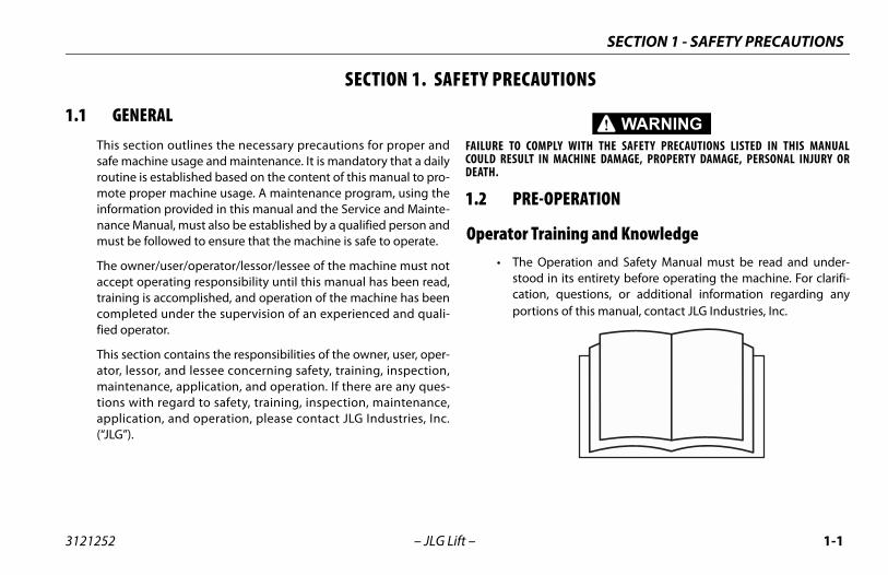
raining and Knowledge Operation and Safety Manual must be read and under-d in its entirety before operating the machine. For clarifi-
on, questions, or additional information regarding anytions of this manual, contact JLG Industries, Inc.
3121252 – JLG Lift –
SECTION 1. SAFETY PRECA
1.1 GENERALThis section outlines the necessary precautions for proper andsafe machine usage and maintenance. It is mandatory that a dailyroutine is established based on the content of this manual to pro-mote proper machine usage. A maintenance program, using theinformation provided in this manual and the Service and Mainte-nance Manual, must also be established by a qualified person andmust be followed to ensure that the machine is safe to operate.
The owner/user/operator/lessor/lessee of the machine must notaccept operating responsibility until this manual has been read,training is accomplished, and operation of the machine has beencompleted under the supervision of an experienced and quali-fied operator.
This section contains the responsibilities of the owner, user, oper-ator, lessor, and lessee concerning safety, training, inspection,maintenance, application, and operation. If there are any ques-tions with regard to safety, training, inspection, maintenance,application, and operation, please contact JLG Industries, Inc.(“JLG”).
FAILURE TO COCOULD RESULTDEATH.
1.2 PRE
Operator T• The
stoocatipor
SECTION 1 - SAFETY PRECAUTIONS
1-2 3121252
pectionns to avoid all hazards in the work area must be
the user before and during operation of the machine.
perate or raise the platform from a position on trucks,ailway cars, floating vessels, scaffolds or other equip-less the application is approved in writing by JLG.
peration, check work area for overhead hazards suchic lines, bridge cranes, and other potential overheadions.
erating surfaces for holes, bumps, drop-offs, obstruc-bris, concealed holes, and other potential hazards.
e work area for hazardous locations. Do not operateine in hazardous environments unless approved forose by JLG.
hat the ground conditions are adequate to supportimum tire load indicated on the tire load decalsn the chassis adjacent to each wheel. Do not travelported surfaces.
– JLG Lift –
• An operator must not accept operating responsibilities untiladequate training has been given by competent and autho-rized persons.
• Allow only those authorized and qualified personnel to oper-ate the machine who have demonstrated that they under-stand the safe and proper operation and maintenance of theunit.
• Read, understand, and obey all DANGERS, WARNINGS, CAU-TIONS, and operating instructions on the machine and in thismanual.
• Ensure that the machine is to be used in a manner which iswithin the scope of its intended application as determined byJLG.
• All operating personnel must be familiar with the emergencycontrols and emergency operation of the machine as specifiedin this manual.
• Read, understand, and obey all applicable employer, local, andgovernmental regulations as they pertain to your utilizationand application of the machine.
Workplace Ins• Precautio
taken by
• Do not otrailers, rment un
• Before oas electrobstruct
• Check options, de
• Check ththe machthat purp
• Ensure tthe maxlocated oon unsup
SECTION 1 - SAFETY PRECAUTIONS
1-3
RATION
hine operation requires your full attention. Bring thehine to a full stop before using any device, i.e. cell phones,-way radios, etc. that will distract your attention fromly operating the machine.
not use the machine for any purpose other than position-personnel, their tools, and equipment.
re operation, the user must be familiar with the machineabilities and operating characteristics of all functions.
er operate a malfunctioning machine. If a malfunctionrs, shut down the machine. Remove the unit from service
notify the proper authorities.
ot remove, modify, or disable any safety devices.
er slam a control switch or lever through neutral to anosite direction. Always return switch to neutral and stopre moving the switch to the next function. Operate con- with slow and even pressure.
not allow personnel to tamper with or operate thehine from the ground with personnel in the platform,pt in an emergency.
3121252 – JLG Lift –
Machine Inspection • Do not operate this machine until the inspections and func-
tional checks as specified in Section 2 of this manual havebeen performed.
• Do not operate this machine until it has been serviced andmaintained according to the maintenance and inspectionrequirements as specified in the machine’s Service and Main-tenance Manual.
• Ensure all safety devices are operating properly. Modificationof these devices is a safety violation.
MODIFICATION OR ALTERATION OF AN AERIAL WORK PLATFORM SHALL BE MADEONLY WITH PRIOR WRITTEN PERMISSION FROM THE MANUFACTURER.
• Do not operate any machine on which the safety or instructionplacards or decals are missing or illegible.
• Check the machine for modifications to original components.Ensure that any modifications have been approved by JLG.
• Avoid accumulation of debris on platform floor. Keep mud, oil,grease, and other slippery substances from footwear and plat-form floor.
1.3 OPE
General • Mac
mactwosafe
• Do ing
• Befocap
• Nevoccuand
• Do n
• Nevoppbefotrols
• Do macexce
SECTION 1 - SAFETY PRECAUTIONS
1-4 3121252
c cylinders are subject to thermal expansion and con-This may result in changes to the boom and/or plat-sition while the machine is stationary. Factors thermal movement can include the length of timeine will remain stationary, hydraulic oil temperature,
air temperature, and boom and platform position.
azards peration, occupants in the platform must wear a fullness with a lanyard attached to an authorized lanyarde point. Attach only one (1) lanyard per lanyarde point..
d exit only through gate area. Use extreme cautiontering or leaving platform. Ensure that the platform is fully lowered. Face the machine when entering orhe platform. Always maintain “three point contact” machine, using two hands and one foot or two feethand at all times during entry and exit.
– JLG Lift –
• Do not carry materials directly on platform railing unlessapproved by JLG.
• When two or more persons are in the platform, the operatorshall be responsible for all machine operations.
• Always ensure that power tools are properly stowed and neverleft hanging by their cord from the platform work area.
• When driving, always position boom over rear axle in line withthe direction of travel. Remember, if boom is over the frontaxle, steer and drive functions will be reversed.
• Do not assist a stuck or disabled machine by pushing or pull-ing except by pulling at the chassis tie-down lugs.
• Fully lower platform and shut off all power before leavingmachine.
• Remove all rings, watches, and jewelry when operatingmachine. Do not wear loose fitting clothing or long hair unre-strained which may become caught or entangled in equip-ment.
• Persons under the influence of drugs or alcohol or who aresubject to seizures, dizziness or loss of physical control mustnot operate this machine.
• Hydraulitraction. form poaffectingthe machambient
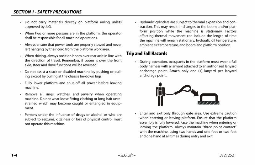
Trip and Fall H• During o
body haranchoraganchorag
• Enter anwhen enassemblyleaving twith theand one
SECTION 1 - SAFETY PRECAUTIONS
1-5
ion Hazards machine is not insulated and does not provide protection contact or proximity to electrical current.
3121252 – JLG Lift –
• Before operating the machine, make sure all gates are closedand fastened in their proper position.
• Keep both feet firmly positioned on the platform floor at alltimes. Never position ladders, boxes, steps, planks, or similaritems on unit to provide additional reach for any purpose.
• Keep oil, mud, and slippery substances cleaned from footwearand the platform floor.
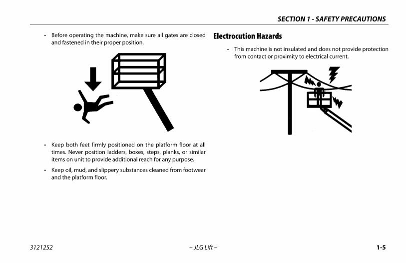
Electrocut• This
from
SECTION 1 - SAFETY PRECAUTIONS
1-6 3121252
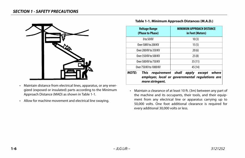
a clearance of at least 10 ft. (3m) between any part ofhine and its occupants, their tools, and their equip-m any electrical line or apparatus carrying up toolts. One foot additional clearance is required forditional 30,000 volts or less.
-1. Minimum Approach Distances (M.A.D.)
e Rangeto Phase)
MINIMUM APPROACH DISTANCEin Feet (Meters)
50 KV 10 (3)
V to 200 KV 15 (5)
V to 350 KV 20 (6)
V to 500 KV 25 (8)
V to 750 KV 35 (11)
V to 1000 KV 45 (14)
requirement shall apply except whereloyer, local or governmental regulations are
re stringent.
– JLG Lift –
• Maintain distance from electrical lines, apparatus, or any ener-gized (exposed or insulated) parts according to the MinimumApproach Distance (MAD) as shown in Table 1-1.
• Allow for machine movement and electrical line swaying.
• Maintainthe macment fro50,000 vevery ad
Table 1
Voltag(Phase
0 to
Over 50K
Over 200 K
Over 350 K
Over 500 K
Over 750 K
NOTE: Thisempmo
SECTION 1 - SAFETY PRECAUTIONS
1-7
azards user must be familiar with the surface before driving. Doexceed the allowable sideslope and grade while driving.
not elevate platform or drive with platform elevated whiler near a sloping, uneven, or soft surface. Ensure machine is
itioned on a firm, level and smooth surface before elevat-platform or driving with the platform in the elevated posi-.
re driving on floors, bridges, trucks, and other surfaces,ck allowable capacity of the surfaces.
3121252 – JLG Lift –
• The minimum approach distance may be reduced if insulatingbarriers are installed to prevent contact, and the barriers arerated for the voltage of the line being guarded. These barriersshall not be part of (or attached to) the machine. The mini-mum approach distance shall be reduced to a distance withinthe designed working dimensions of the insulating barrier.This determination shall be made by a qualified person inaccordance with the employer, local, or governmental require-ments for work practices near energized equipment
DO NOT MANEUVER MACHINE OR PERSONNEL INSIDE PROHIBITED ZONE (MAD).ASSUME ALL ELECTRICAL PARTS AND WIRING ARE ENERGIZED UNLESS KNOWN OTH-ERWISE.
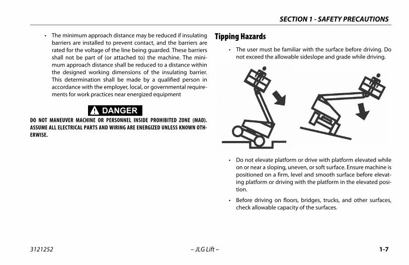
Tipping H• The
not
• Do on oposing tion
• Befoche
SECTION 1 - SAFETY PRECAUTIONS
1-8 3121252
perate the machine when wind conditions exceed 28.5 m/s). Refer to Table 1-2, Beaufort Scale (For Refer-y).
ncrease the surface area of the platform or the load.of the area exposed to the wind will decrease stabil-
increase the platform size with unauthorized deckns or attachments.
assembly or platform is in a position that one or morere off the ground, all persons must be removed beforeng to stabilize the machine. Use cranes, forklift trucks,appropriate equipment to stabilize machine.
– JLG Lift –
• Never exceed the maximum work load as specified on theplatform. Keep all loads within the confines of the platform,unless authorized by JLG.
• Keep the chassis of the machine a minimum of 2 ft. (0.6m)from holes, bumps, drop-offs, obstructions, debris, concealedholes, and other potential hazards at the ground level.
• Do not push or pull any object with the boom.
• Never attempt to use the machine as a crane. Do not tie-offmachine to any adjacent structure. Never attach wire, cable, orany similar items to platform.
• Do not omph (12ence Onl
• Do not iIncrease ity.
• Do not extensio
• If boom wheels aattemptior other
SECTION 1 - SAFETY PRECAUTIONS
1-9
nce Only)
Land Conditions
vertically
le in smoke
ed skin. Leaves rustle
twigs in constant motion
er raised. Small branches begin to move.
.
otion. Flags waving near horizontal. Umbrella use
ion. Effort needed to walk against the wind.
trees. Cars veer on road.
age.
3121252 – JLG Lift –
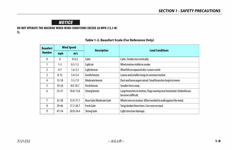
DO NOT OPERATE THE MACHINE WHEN WIND CONDITIONS EXCEED 28 MPH (12.5 M/S).
Table 1-2. Beaufort Scale (For Refere
Beaufort Number
Wind SpeedDescription
mph m/s
0 0 0-0.2 Calm Calm. Smoke rises
1 1-3 0.3-1.5 Light air Wind motion visib
2 4-7 1.6-3.3 Light breeze Wind felt on expos
3 8-12 3.4-5.4 Gentle breeze Leaves and smaller
4 13-18 5.5-7.9 Moderate breeze Dust and loose pap
5 19-24 8.0-10.7 Fresh breeze Smaller trees sway
6 25-31 10.8-13.8 Strong breeze Large branches in mbecomes difficult.
7 32-38 13.9-17.1 Near Gale/Moderate Gale Whole trees in mot
8 39-46 17.2-20.7 Fresh Gale Twigs broken from
9 47-54 20.8-24.4 Strong Gale Light structure dam
SECTION 1 - SAFETY PRECAUTIONS
1-1 3121252
Cru n-operating personnel at least 6 ft. (1.8m) away from during all driving and swing operations.
ll travel conditions, the operator must limit travelcording to conditions of ground surface, congestion, slope, location of personnel, and other factors whichse collision or injury to personnel.
of stopping distances in all drive speeds. When driv-h speed, switch to low speed before stopping. Travel low speed only.
se high speed drive in restricted or close quarters orving in reverse.
extreme caution at all times to prevent obstacles fromr interfering with operating controls and persons in
orm.
that operators of other overhead and floor levels are aware of the aerial work platform’s presence. Dis-power to overhead cranes.
rsonnel not to work, stand, or walk under a raised platform. Position barricades on floor if necessary.
0 – JLG Lift –
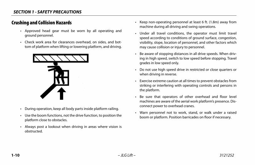
shing and Collision Hazards• Approved head gear must be worn by all operating and
ground personnel.
• Check work area for clearances overhead, on sides, and bot-tom of platform when lifting or lowering platform, and driving.
• During operation, keep all body parts inside platform railing.
• Use the boom functions, not the drive function, to position theplatform close to obstacles.
• Always post a lookout when driving in areas where vision isobstructed.
• Keep nomachine
• Under aspeed acvisibility,may cau
• Be awareing in higgrades in
• Do not uwhen dri
• Exercise striking othe platf
• Be sure machineconnect
• Warn peboom or
SECTION 1 - SAFETY PRECAUTIONS
1-11
INTENANCEb-section contains general safety precautions which musterved during maintenance of this machine. Additional pre-ns to be observed during machine maintenance ared at the appropriate points in this manual and in the Ser-d Maintenance Manual. It is of utmost importance thatnance personnel pay strict attention to these precautionsd possible injury to personnel or damage to the machineerty. A maintenance program must be established by a
ied person and must be followed to ensure that thee is safe.
nce Hazardst off power to all controls and ensure that all moving partssecured from inadvertent motion prior to performing anystments or repairs.
er work under an elevated platform until it has been fullyered to the full down position, if possible, or otherwiseported and restrained from movement with appropriatety props, blocking, or overhead supports.
NOT attempt to repair or tighten any hydraulic hoses or fit-s while the machine is powered on or when the hydraulicem is under pressure.
ays relieve hydraulic pressure from all hydraulic circuitsre loosening or removing hydraulic components.
3121252 – JLG Lift –
1.4 TOWING, LIFTING, AND HAULING• Never allow personnel in platform while towing, lifting, or
hauling.
• This machine should not be towed, except in the event ofemergency, malfunction, power failure, or loading/unloading.Refer to the Emergency Procedures section of this manual foremergency towing procedures.
• Ensure boom is in the stowed position and the turntablelocked prior to towing, lifting or hauling. The platform must becompletely empty of tools.
• When lifting machine, lift only at designated areas of themachine. Lift the unit with equipment of adequate capacity.
• Refer to the Machine Operation section of this manual for lift-ing information.
1.5 MAThis sube obscautioinsertevice anmainteto avoior propqualifmachin
Maintena• Shu
are adju
• Nevlowsupsafe
• DO tingsyst
• Alwbefo
SECTION 1 - SAFETY PRECAUTIONS
1-1 3121252
se machine as a ground for welding.
rforming welding or metal cutting operations, pre- must be taken to protect the chassis from direct to weld and metal cutting spatter.
fuel the machine with the engine running.
approved non-flammable cleaning solvents.
eplace items critical to stability, such as batteries ors, with items of different weight or specification. Doify unit in any way to affect stability.
the Service and Maintenance Manual for the weightsl stability items.
LTERATION OF AN AERIAL WORK PLATFORM SHALL BE MADERITTEN PERMISSION FROM THE MANUFACTURER.
2 – JLG Lift –
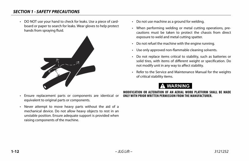
• DO NOT use your hand to check for leaks. Use a piece of card-board or paper to search for leaks. Wear gloves to help protecthands from spraying fluid.
• Ensure replacement parts or components are identical orequivalent to original parts or components.
• Never attempt to move heavy parts without the aid of amechanical device. Do not allow heavy objects to rest in anunstable position. Ensure adequate support is provided whenraising components of the machine.
• Do not u
• When pecautionsexposure
• Do not re
• Use only
• Do not rsolid tirenot mod
• Refer to of critica
MODIFICATION OR AONLY WITH PRIOR W
SECTION 1 - SAFETY PRECAUTIONS
1-13
ID IS HIGHLY CORROSIVE. AVOID CONTACT WITH SKIN AND ALL TIMES. IMMEDIATELY RINSE ANY CONTACTED AREA WITH AND SEEK MEDICAL ATTENTION.
rge batteries only in a well ventilated area.
id overfilling the battery fluid level. Add distilled water toeries only after the batteries are fully charged.
3121252 – JLG Lift –
Battery Hazards• Always disconnect batteries when servicing electrical compo-
nents or when performing welding on the machine.
• Do not allow smoking, open flame, or sparks near battery dur-ing charging or servicing.
• Do not contact tools or other metal objects across the batteryterminals.
• Always wear hand, eye, and face protection when servicingbatteries. Ensure that battery acid does not come in contactwith skin or clothing.
BATTERY FLUCLOTHING ATCLEAN WATER
• Cha
• Avobatt
SECTION 1 - SAFETY PRECAUTIONS
1-1 3121252
4 – JLG Lift –NOTES:
S, MACHINE PREPARATION, AND INSPECTION
2-1
REPARATION, AND INSPECTION
e safest means to operate the machine where overheadstructions, other moving equipment, and obstacles,pressions, holes, drop-offs.
eans to avoid the hazards of unprotected electrical con-ctors.
ecific job requirements or machine application.
upervisiong must be done under the supervision of a qualified per- an open area free of obstructions until the trainee hasped the ability to safely control and operate the machine.
esponsibilityerator must be instructed that he/she has the responsibil- authority to shut down the machine in case of a malfunc- other unsafe condition of either the machine or the job
SECTION 2 - USER RESPONSIBILITIE
3121252 – JLG Lift –
SECTION 2. USER RESPONSIBILITIES, MACHINE P
2.1 PERSONNEL TRAININGThe aerial platform is a personnel handling device; so it is neces-sary that it be operated and maintained only by trained person-nel.
Persons under the influence of drugs or alcohol or who are sub-ject to seizures, dizziness or loss of physical control must notoperate this machine.
Operator TrainingOperator training must cover:
1. Use and limitations of the controls in the platform and at theground, emergency controls and safety systems.
2. Control labels, instructions, and warnings on the machine.
3. Rules of the employer and government regulations.
4. Use of approved fall protection device.
5. Enough knowledge of the mechanical operation of themachine to recognize a malfunction or potential malfunc-tion.
6. Thobde
7. Mdu
8. Sp
Training STraininson indevelo
Operator RThe opity andtion orsite.
SECTION 2 - USER RESPONSIBILITIES, MACHINE PREPARATION, AND INSPECTION
2-2 3121252
2.2. RECOGNIZES A FACTORY TRAINED SERVICE TECHNICIAN AS A
UCCESSFULLY COMPLETED THE JLG SERVICE TRAINING SCHOOL PRODUCT MODEL.
– JLG Lift –
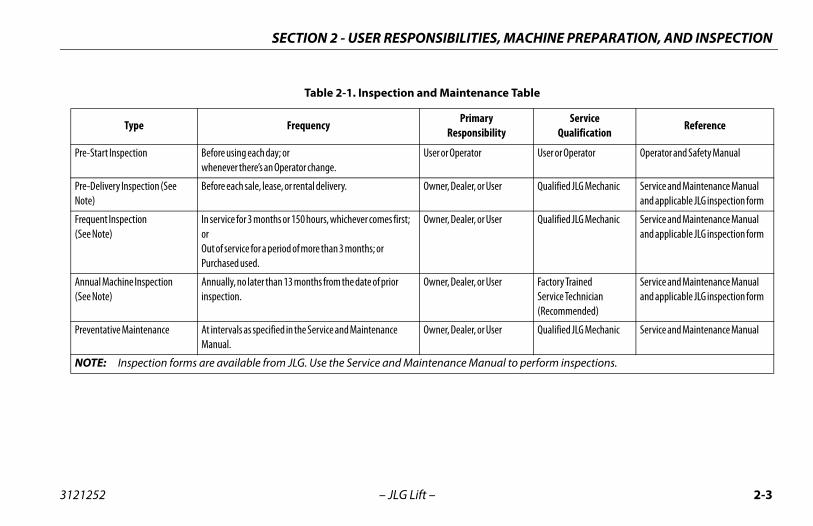
PREPARATION, INSPECTION, AND MAINTENANCEThe following table covers the periodic machine inspections andmaintenance required by JLG Industries, Inc. Consult local regula-tions for further requirements for aerial work platforms. The fre-quency of inspections and maintenance must be increased asnecessary when the machine is used in a harsh or hostile environ-ment, if the machine is used with increased frequency, or if themachine is used in a severe manner.
JLG INDUSTRIES, INCPERSON WHO HAS SFOR THE SPECIFIC JLG
S, MACHINE PREPARATION, AND INSPECTION
2-3
nce Table
yility
Service Qualification
Reference
User or Operator Operator and Safety Manual
ser Qualified JLG Mechanic Service and Maintenance Manual and applicable JLG inspection form
ser Qualified JLG Mechanic Service and Maintenance Manual and applicable JLG inspection form
ser Factory TrainedService Technician(Recommended)
Service and Maintenance Manual and applicable JLG inspection form
ser Qualified JLG Mechanic Service and Maintenance Manual
ual to perform inspections.
SECTION 2 - USER RESPONSIBILITIE
3121252 – JLG Lift –
Table 2-1. Inspection and Maintena
Type FrequencyPrimar
Responsib
Pre-Start Inspection Before using each day; or whenever there’s an Operator change.
User or Operator
Pre-Delivery Inspection (See Note)
Before each sale, lease, or rental delivery. Owner, Dealer, or U
Frequent Inspection(See Note)
In service for 3 months or 150 hours, whichever comes first; orOut of service for a period of more than 3 months; orPurchased used.
Owner, Dealer, or U
Annual Machine Inspection(See Note)
Annually, no later than 13 months from the date of prior inspection.
Owner, Dealer, or U
Preventative Maintenance At intervals as specified in the Service and Maintenance Manual.
Owner, Dealer, or U
NOTE: Inspection forms are available from JLG. Use the Service and Maintenance Man
SECTION 2 - USER RESPONSIBILITIES, MACHINE PREPARATION, AND INSPECTION
2-4 3121252
Pre tion and Safety Manuals – Make sure a copy of theor and Safety Manual, AEM Safety Manual (ANSI mar-ly), and ANSI Manual of Responsibilities (ANSI mar-
nly) is enclosed in the weather resistant storageer.
Around” Inspection – Refer to Figure 2-2.
y – Charge as required.
ulic Oil – Check the hydraulic oil level. Ensure hydrau- added as required.
ories/Attachments - Reference the Operator andManual of each attachment or accessory installedhe machine for specific inspection, operation, andnance instructions.
– JLG Lift –
-Start InspectionThe Pre-Start Inspection should include each of the following:
1. Cleanliness – Check all surfaces for leakage (oil, fuel, or bat-tery fluid) or foreign objects. Report any leakage to theproper maintenance personnel.
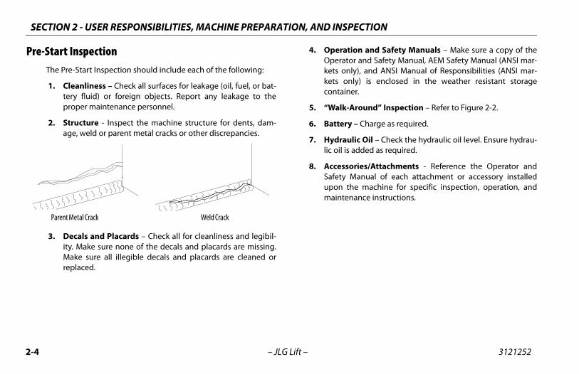
2. Structure - Inspect the machine structure for dents, dam-age, weld or parent metal cracks or other discrepancies.
3. Decals and Placards – Check all for cleanliness and legibil-ity. Make sure none of the decals and placards are missing.Make sure all illegible decals and placards are cleaned orreplaced.
4. OperaOperatkets onkets ocontain
5. “Walk-
6. Batter
7. Hydralic oil is
8. AccessSafety upon tmainte
Parent Metal Crack Weld Crack
S, MACHINE PREPARATION, AND INSPECTION
2-5
om the platform control console:
. Ensure that the control console is firmly secured in theproper location;
. Check that all guards protecting the switches or locksare in place;
. Operate all functions and ensure proper operation;
. Ensure that all machine functions are disabled whenthe Emergency Stop Button is pushed in.
. Ensure that all machine functions stop when the foot-switch is released.
ith the platform in the stowed position:
. Drive the machine on a grade, not to exceed the ratedgradeability, and stop to ensure the brakes hold;
. Check that the tilt indicator is illuminated to ensureproper operation.
ing the boom over either of the rear tires and ensure thate Drive Orientation indicator illuminates and that theive Orientation Override switch must be used for the drivenction to operate.
SECTION 2 - USER RESPONSIBILITIE
3121252 – JLG Lift –
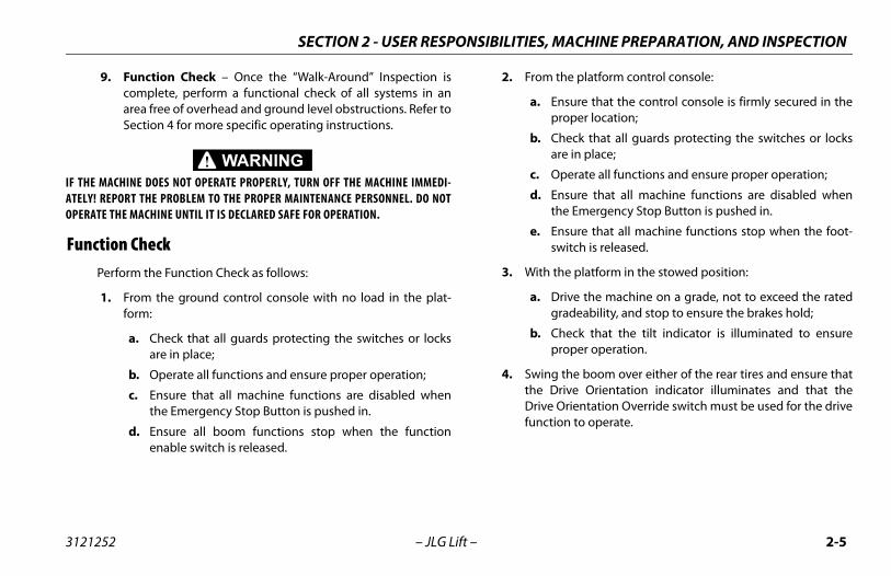
9. Function Check – Once the “Walk-Around” Inspection iscomplete, perform a functional check of all systems in anarea free of overhead and ground level obstructions. Refer toSection 4 for more specific operating instructions.
IF THE MACHINE DOES NOT OPERATE PROPERLY, TURN OFF THE MACHINE IMMEDI-ATELY! REPORT THE PROBLEM TO THE PROPER MAINTENANCE PERSONNEL. DO NOTOPERATE THE MACHINE UNTIL IT IS DECLARED SAFE FOR OPERATION.
Function CheckPerform the Function Check as follows:
1. From the ground control console with no load in the plat-form:
a. Check that all guards protecting the switches or locksare in place;
b. Operate all functions and ensure proper operation;
c. Ensure that all machine functions are disabled whenthe Emergency Stop Button is pushed in.
d. Ensure all boom functions stop when the functionenable switch is released.
2. Fr
a
b
c
d
e
3. W
a
b
4. SwthDrfu
SECTION 2 - USER RESPONSIBILITIES, MACHINE PREPARATION, AND INSPECTION
2-6 3121252
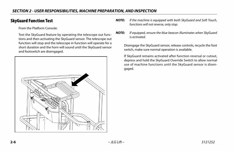
Sky achine is equipped with both SkyGuard and Soft Touch,s will not reverse, only stop.
ed, ensure the blue beacon illuminates when SkyGuardted.
the SkyGuard sensor, release controls, recycle the foote sure normal operation is available.
remains activated after function reversal or cutout, hold the SkyGuard Override Switch to allow normal
hine functions until the SkyGuard sensor is disen-
– JLG Lift –
Guard Function Test From the Platform Console:
Test the SkyGuard feature by operating the telescope out func-tions and then activating the SkyGuard sensor. The telescope outfunction will stop and the telescope in function will operate for ashort duration and the horn will sound until the SkyGuard sensorand footswitch are disengaged.
NOTE: If the mfunction
NOTE: If equippis activa
Disengage switch, mak
If SkyGuarddepress anduse of macgaged.
S, MACHINE PREPARATION, AND INSPECTION
2-7
re
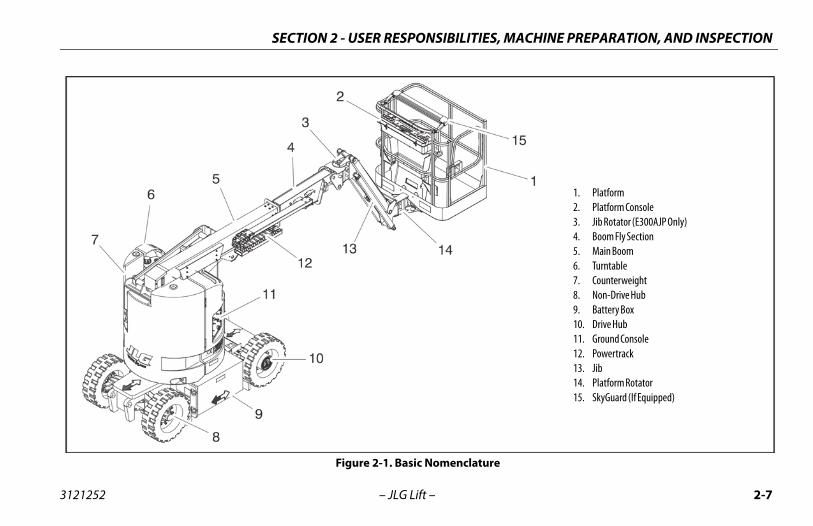
1. Platform2. Platform Console3. Jib Rotator (E300AJP Only)4. Boom Fly Section5. Main Boom6. Turntable7. Counterweight8. Non-Drive Hub9. Battery Box10. Drive Hub11. Ground Console12. Powertrack13. Jib14. Platform Rotator15. SkyGuard (If Equipped)
SECTION 2 - USER RESPONSIBILITIE
3121252 – JLG Lift –
Figure 2-1. Basic Nomenclatu
SECTION 2 - USER RESPONSIBILITIES, MACHINE PREPARATION, AND INSPECTION
2-8 3121252
eet 1 of 3
– JLG Lift –
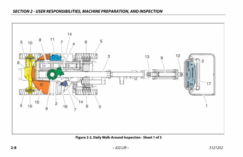
Figure 2-2. Daily Walk-Around Inspection - Sh
S, MACHINE PREPARATION, AND INSPECTION
2-9
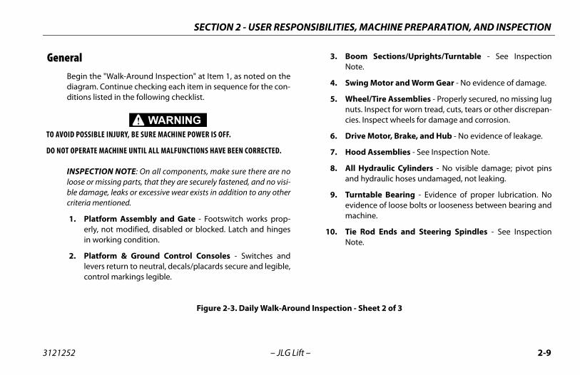
oom Sections/Uprights/Turntable - See Inspectionote.
wing Motor and Worm Gear - No evidence of damage.
heel/Tire Assemblies - Properly secured, no missing luguts. Inspect for worn tread, cuts, tears or other discrepan-ies. Inspect wheels for damage and corrosion.
rive Motor, Brake, and Hub - No evidence of leakage.
ood Assemblies - See Inspection Note.
ll Hydraulic Cylinders - No visible damage; pivot pinsnd hydraulic hoses undamaged, not leaking.
urntable Bearing - Evidence of proper lubrication. Novidence of loose bolts or looseness between bearing andachine.
ie Rod Ends and Steering Spindles - See Inspectionote.
- Sheet 2 of 3
SECTION 2 - USER RESPONSIBILITIE
3121252 – JLG Lift –
GeneralBegin the "Walk-Around Inspection" at Item 1, as noted on thediagram. Continue checking each item in sequence for the con-ditions listed in the following checklist.
TO AVOID POSSIBLE INJURY, BE SURE MACHINE POWER IS OFF.
DO NOT OPERATE MACHINE UNTIL ALL MALFUNCTIONS HAVE BEEN CORRECTED.
INSPECTION NOTE: On all components, make sure there are noloose or missing parts, that they are securely fastened, and no visi-ble damage, leaks or excessive wear exists in addition to any othercriteria mentioned.
1. Platform Assembly and Gate - Footswitch works prop-erly, not modified, disabled or blocked. Latch and hingesin working condition.
2. Platform & Ground Control Consoles - Switches andlevers return to neutral, decals/placards secure and legible,control markings legible.
3. BN
4. S
5. Wnc
6. D
7. H
8. Aa
9. Tem
10. TN
Figure 2-3. Daily Walk-Around Inspection
SECTION 2 - USER RESPONSIBILITIES, MACHINE PREPARATION, AND INSPECTION
2-1 3121252
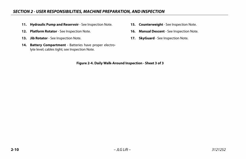
erweight - See Inspection Note.
al Descent - See Inspection Note.
ard - See Inspection Note.
eet 3 of 3
0 – JLG Lift –
11. Hydraulic Pump and Reservoir - See Inspection Note.
12. Platform Rotator - See Inspection Note.
13. Jib Rotator - See Inspection Note.
14. Battery Compartment - Batteries have proper electro-lyte level; cables tight; see Inspection Note.
15. Count
16. Manu
17. SkyGu
Figure 2-4. Daily Walk-Around Inspection - Sh
N 3 - MACHINE CONTROLS AND INDICATORS
3-1
ND INDICATORS
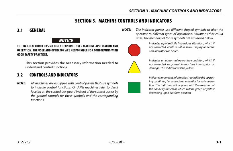
indicator panels use different shaped symbols to alert therator to different types of operational situations that could
se. The meaning of those symbols are explained below.Indicates a potentially hazardous situation, which ifnot corrected, could result in serious injury or death.This indicator will be red.
Indicates an abnormal operating condition, which ifnot corrected, may result in machine interruption ordamage. This indicator will be yellow.
Indicates important information regarding the operat-ing condition, i.e. procedures essential for safe opera-tion. This indicator will be green with the exception ofthe capacity indicator which will be green or yellowdepending upon platform position.
SECTIO
3121252 – JLG Lift –
SECTION 3. MACHINE CONTROLS A
3.1 GENERAL
THE MANUFACTURER HAS NO DIRECT CONTROL OVER MACHINE APPLICATION ANDOPERATION. THE USER AND OPERATOR ARE RESPONSIBLE FOR CONFORMING WITHGOOD SAFETY PRACTICES.
This section provides the necessary information needed tounderstand control functions.
3.2 CONTROLS AND INDICATORS
NOTE: All machines are equipped with control panels that use symbolsto indicate control functions. On ANSI machines refer to decallocated on the control box guard in front of the control box or bythe ground controls for these symbols and the correspondingfunctions.
NOTE: Theopeari
SECTION 3 - MACHINE CONTROLS AND INDICATORS
3-2 3121252
TO ATOGGOFF P
Gro
(S
NOT
NOT
NOT
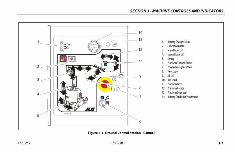
Charge Status
LED lights indicate charge status of battery. Green;es 100% charged. Yellow; indicates charger on. Red;es abnormal battery condition.
n Enable
able switch must be held "DOWN" to enable all boomls when the machine power is on.
oom Lift
s raising/lowering of the main boom when position- or down.
Boom Lift
s raising and lowering of the upright and lower.
s 350 degrees non-continuous turntable rotation. Toe SWING, position switch to LEFT or RIGHT.
– JLG Lift –
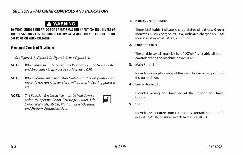
VOID SERIOUS INJURY, DO NOT OPERATE MACHINE IF ANY CONTROL LEVERS ORLE SWITCHES CONTROLLING PLATFORM MOVEMENT DO NOT RETURN TO THEOSITION WHEN RELEASED.
und Control Station
ee Figure 3-1., Figure 3-2., Figure 3-3. and Figure 3-4. )
E: When machine is shut down the Platform/Ground Select switchand Emergency Stop must be positioned to OFF.
E: When Power/Emergency Stop Switch is in the on position andmotor is not running, an alarm will sound, indicating power ison.
E: The Function Enable switch must be held down inorder to operate Boom Telescope, Lower Lift,Swing, Main Lift, Jib Lift, Platform Level Override,and Platform Rotate functions.
1. Battery
Three indicatindicat
2. Functio
The encontro
3. Main B
Provideing up
4. Lower
Providebooms
5. Swing
Provideactivat
N 3 - MACHINE CONTROLS AND INDICATORS
3-3
- E300AJ
1. Battery Charge Status2. Function Enable3. Main Boom Lift4. Lower Boom Lift5. Swing6. Platform/Ground Select7. Power/Emergency Stop8. Telescope9. Jib Lift10. Not Used11. Platform Level12. Platform Rotate13. Platform Overload14. Battery Condition/Hourmeter
SECTIO
3121252 – JLG Lift –
1001109630 B
1
2
3
4
5
6
7
8
9
11
12
13
14
Figure 3-1. Ground Control Station
SECTION 3 - MACHINE CONTROLS AND INDICATORS
3-4 3121252
stem Override (MSSO) (CE Only)
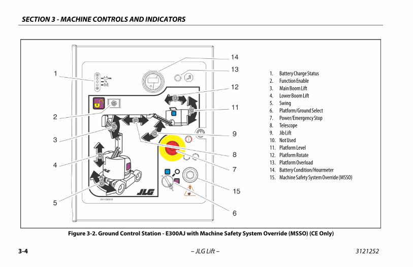
1. Battery Charge Status2. Function Enable3. Main Boom Lift4. Lower Boom Lift5. Swing6. Platform/Ground Select7. Power/Emergency Stop8. Telescope9. Jib Lift10. Not Used11. Platform Level12. Platform Rotate13. Platform Overload14. Battery Condition/Hourmeter15. Machine Safety System Override (MSSO)
– JLG Lift –
Figure 3-2. Ground Control Station - E300AJ with Machine Safety Sy
N 3 - MACHINE CONTROLS AND INDICATORS
3-5
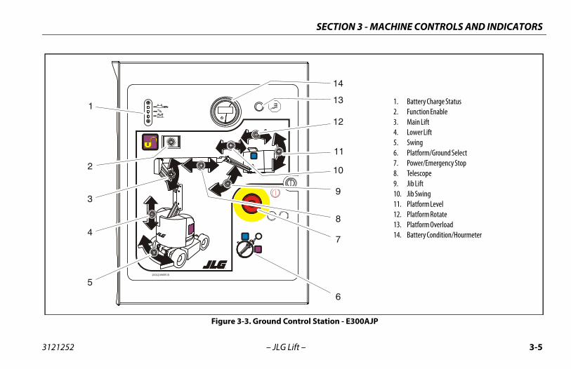
1. Battery Charge Status2. Function Enable3. Main Lift4. Lower Lift5. Swing6. Platform/Ground Select 7. Power/Emergency Stop8. Telescope9. Jib Lift10. Jib Swing11. Platform Level12. Platform Rotate13. Platform Overload14. Battery Condition/Hourmeter
E300AJP
SECTIO
3121252 – JLG Lift –
1001109655 B
1
2
3
4
5
6
7
8
9
10
11
12
13
14
Figure 3-3. Ground Control Station -
SECTION 3 - MACHINE CONTROLS AND INDICATORS
3-6 3121252
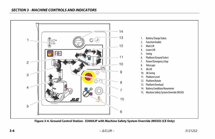
1. Battery Charge Status2. Function Enable3. Main Lift4. Lower Lift5. Swing6. Platform/Ground Select 7. Power/Emergency Stop8. Telescope9. Jib Lift10. Jib Swing11. Platform Level12. Platform Rotate13. Platform Overload14. Battery Condition/Hourmeter15. Machine Safety System Override (MSSO)
ystem Override (MSSO) (CE Only)
– JLG Lift –
Figure 3-4. Ground Control Station - E300AJP with Machine Safety S
N 3 - MACHINE CONTROLS AND INDICATORS
3-7
HINE IS SHUT DOWN THE POWER/EMERGENCY STOP SWITCH MUST BE THE OFF POSITION TO PREVENT DRAINING THE BATTERIES.
wer/Emergency Stop Switch
two-position red mushroom shaped switch supplieswer to PLATFORM/GROUND SELECT switch when pulledt (on). When pushed in (off ), power is shut off to the PLAT-RM/GROUND SELECT switch.
lescope Control
ovides extension and retraction of the boom.
SECTIO
3121252 – JLG Lift –
NOTE: When the Platform/Ground Select Switch is in the center posi-tion, power is shut off to the controls at both operating stations.Remove the key to prevent the controls from being actuated. Thekey is removable in the platform position on CE specificationmachines. The key must be available to ground personnel in theevent of an emergency.
6. Platform/Ground Select Switch
The three position, key operated switch supplies power tothe platform control console when positioned to PLATFORM.With the switch key turned to the GROUND position, poweris shut off to platform and only ground controls are opera-ble.
WHEN THE MACPOSITIONED TO
7. Po
A poouFO
8. Te
Pr
SECTION 3 - MACHINE CONTROLS AND INDICATORS
3-8 3121252
ONLYTHE FALL
m Rotate
s rotation of the platform.
m Overload (If equipped)
es the platform has been overloaded.
Indicator and Hourmeter
ttery indicator displays the present charge of the bat-The hourmeter counts the amount of machine oper-ime, up to 9,999.9 hours, and cannot be reset.
e Safety System Override (MSSO) (CE
s emergency override of functionls that are locked out in the event ofense System activation.
– JLG Lift –
9. Jib Lift
Provides raising and lowering of the jib.
10. Jib Swing
Allows swinging of the jib.
USE THE PLATFORM LEVELING OVERRIDE FUNCTION FOR SLIGHT LEVELING OFPLATFORM. INCORRECT USE COULD CAUSE THE LOAD/OCCUPANTS TO SHIFT OR. FAILURE TO DO SO COULD RESULT IN DEATH OR SERIOUS INJURY.
11. Platform Leveling Override
A three position switch allows the operator to adjust theautomatic self leveling system. This switch is used to adjustplatform level in situations such as ascending/descending agrade.
12. Platfor
Provide
13. Platfor
Indicat
14. Battery
The bateries. ating t
15. MachinOnly)
ProvidecontroLoad S
N 3 - MACHINE CONTROLS AND INDICATORS
3-9
PLATFORM LEVELING OVERRIDE FUNCTION FOR SLIGHT LEVELING OF. INCORRECT USE COULD CAUSE THE LOAD/OCCUPANTS TO SHIFT ORTO DO SO COULD RESULT IN DEATH OR SERIOUS INJURY.
atform Leveling Override
three position switch allows the operator to adjust thetomatic self leveling system. This switch is used to adjust
atform level in situations such as ascending/descending aade.
rn
push-type HORN switch supplies electrical power to an dible warning device when pressed.
wer/Emergency Stop Switch
two-position red mushroom shaped switch furnisheswer to PLATFORM Controls when pulled out (on). Whenshed in (off ), power is shut off to the platform functions.
SECTIO
3121252 – JLG Lift –
Platform Station
(See Figure 3-5., Platform Control Console)
TO AVOID SERIOUS INJURY, DO NOT OPERATE MACHINE IF ANY CONTROL LEVERS ORTOGGLE SWITCHES CONTROLLING PLATFORM MOVEMENT DO NOT RETURN TO THEOFF OR NEUTRAL POSITION WHEN RELEASED.
1. Posi-Track
When one wheel is slipping and the machine is not descend-ing a grade, automatic traction control will provide addedtorque to both drive wheels. While this function is auto-matic, it may also be manually engaged by moving the tog-gle switch to the forward position. Positrac will be engagedfor approximately 20 seconds.
ONLY USE THE THE PLATFORMFALL. FAILURE
2. Pl
A auplgr
3. Ho
A au
4. Po
A popu
SECTION 3 - MACHINE CONTROLS AND INDICATORS
3-1 3121252
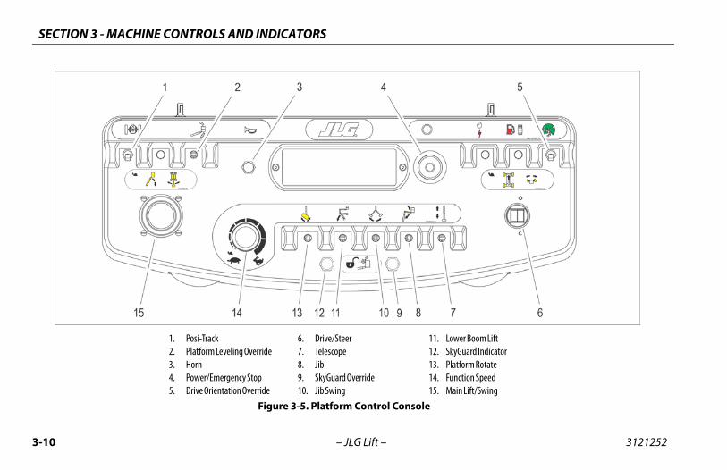
. Lower Boom Lift
. SkyGuard Indicator
. Platform Rotate
. Function Speed
. Main Lift/Swing
0 – JLG Lift –
1. Posi-Track2. Platform Leveling Override3. Horn4. Power/Emergency Stop5. Drive Orientation Override
6. Drive/Steer7. Telescope8. Jib9. SkyGuard Override10. Jib Swing
1112131415
Figure 3-5. Platform Control Console
N 3 - MACHINE CONTROLS AND INDICATORS
3-11
lescope
ovides extension and retraction of the main boom.
ovides for raising or lowering of the jib by positioning up/wn.
yGuard Override Switch (Ifuipped)
e switch enables functions cut out the Skyguard system to be operatedain, allowing the operator to resume use of machine func-ns.
Swing (If equipped)
ovides jib swing right or left.
wer Boom Lift
ovides for raising and lowering of Upright when posi-ned to UP or DOWN.
SECTIO
3121252 – JLG Lift –
5. Drive Orientation Override
When the boom is swung over the rear tires or further ineither direction, the Drive Orientation indicator will illumi-nate when the drive function is selected. Push and releasethe switch, and within 3 seconds move the Drive/Steer con-trol to activate drive or steer. Before driving, locate the black/white orientation arrows on both the chassis and the plat-form controls. Move the drive controls in a direction match-ing the directional arrows.
NOTE: To operate the Drive joystick, pull up on the locking ring belowthe handle.
NOTE: The Drive joystick is spring loaded and will automatically returnto neutral (off) position when released.
6. Drive/Steer
Push forward to drive forward, pull back to drive in reverse.Steering is accomplished via a thumb-activated rockerswitch on the end of the steer handle.
NOTE: When boom is positioned above horizontal and Posi-Trackengaged or Function speed are positioned to high, high functionspeeds are automatically cut out and the machine continues tooperate at a lower speed.
7. Te
Pr
8. Jib
Prdo
9. Skeq
Thbyagtio
10. Jib
Pr
11. Lo
Prtio
SECTION 3 - MACHINE CONTROLS AND INDICATORS
3-1 3121252
ate the Main Boom Lift/Swing joystick, pull up on thering below the handle.
in Boom Lift/Swing joystick is spring loaded and willtically return to neutral (off ) position when released.
ift/Swing Controller
s main lift and swing. Push forward to lift up, pullard to boom down. Move right to swing right, moveswing left. Moving the joystick activates switches toe the functions selected. Proportional control of thesens can be attained by using the Function Speed
2 – JLG Lift –
12. SkyGuard Indicator (If Equipped)
Indicates the SkyGuard sensor has been activated. All con-trols are cut out until the override button is pushed. Controlswill then work normally.
13. Platform Rotate
Provides rotation of the platform when positioned to theright or left.
14. Function Speed Control
Adjusts speed of Boom and Swing Functions. Rotate coun-terclockwise for slower speed and clockwise for faster speed.To adjust Drive, Swing, and Main Boom Lift to creep, turnknob fully counterclockwise until it clicks.
NOTE: To operlocking
NOTE: The Maautoma
15. Main L
Providebackwleft to providfunctioknob.
N 3 - MACHINE CONTROLS AND INDICATORS
3-13
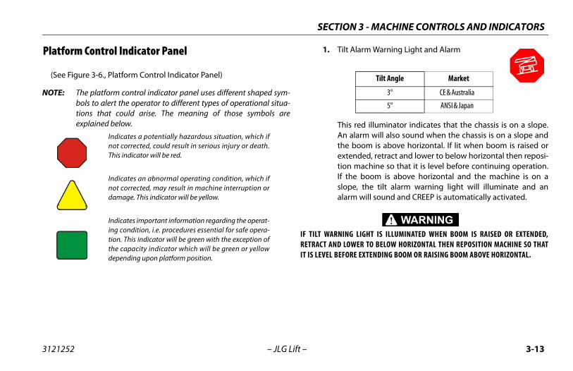
lt Alarm Warning Light and Alarm
is red illuminator indicates that the chassis is on a slope. alarm will also sound when the chassis is on a slope and
e boom is above horizontal. If lit when boom is raised ortended, retract and lower to below horizontal then reposi-n machine so that it is level before continuing operation.the boom is above horizontal and the machine is on ape, the tilt alarm warning light will illuminate and an
arm will sound and CREEP is automatically activated.
NG LIGHT IS ILLUMINATED WHEN BOOM IS RAISED OR EXTENDED,LOWER TO BELOW HORIZONTAL THEN REPOSITION MACHINE SO THATORE EXTENDING BOOM OR RAISING BOOM ABOVE HORIZONTAL.
Tilt Angle Market
3° CE & Australia
5° ANSI & Japan
SECTIO
3121252 – JLG Lift –
Platform Control Indicator Panel
(See Figure 3-6., Platform Control Indicator Panel)
NOTE: The platform control indicator panel uses different shaped sym-bols to alert the operator to different types of operational situa-tions that could arise. The meaning of those symbols areexplained below.
1. Ti
ThAnthextioIf sloal
IF TILT WARNIRETRACT AND IT IS LEVEL BEF
Indicates a potentially hazardous situation, which ifnot corrected, could result in serious injury or death.This indicator will be red.
Indicates an abnormal operating condition, which ifnot corrected, may result in machine interruption ordamage. This indicator will be yellow.
Indicates important information regarding the operat-ing condition, i.e. procedures essential for safe opera-tion. This indicator will be green with the exception ofthe capacity indicator which will be green or yellowdepending upon platform position.
SECTION 3 - MACHINE CONTROLS AND INDICATORS
3-1 3121252
r likely causes of a system fault are:
e seven second enable time has been allowed topse or a function was selected before depressing theotswitch. The system reads this condition as a fault,st as it would if the footswitch were jammed in thepressed position or a function switch were stuck ine on position. Re-depress the footswitch to power thentrols and extinguish the light.
e maximum power limit has been reached and theachine is not moving. This could happen when theachine is stuck or when attempting to travel overugh terrain or on steep grades which exceed theted gradeability of the machine. This condition ismparable to stalling the engine by asking it to pro-
de more power than it was designed to do.
e batteries are nearly depleted, and should bearged very soon to prevent having the machine stop an inconvenient place.
ere is some other fault in one of the circuits. Deter-ine the cause by counting the flash code, a number ofshes followed by a pause followed by another num-r of flashes, and refer to the service manual.
rientation Indicator
the boom is swung beyond the rear drive tires or fur-
4 – JLG Lift –
2. Platform Overload (If equipped)
Indicates the platform has been overloaded.
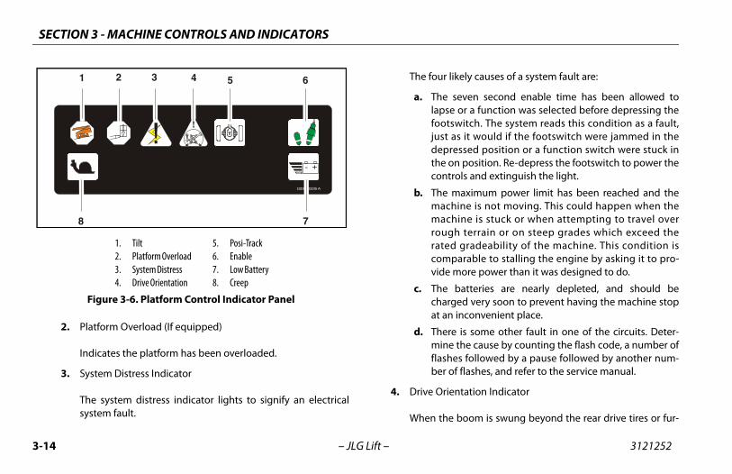
3. System Distress Indicator
The system distress indicator lights to signify an electricalsystem fault.
The fou
a. Thlafojudethco
b. Thmmroracovi
c. Thchat
d. Thmflabe
4. Drive O
When
1001110226 A
+-
8 7
1 65432
1. Tilt2. Platform Overload3. System Distress4. Drive Orientation
5. Posi-Track6. Enable7. Low Battery8. Creep
Figure 3-6. Platform Control Indicator Panel
N 3 - MACHINE CONTROLS AND INDICATORS
3-15
UST BE ADJUSTED IF FUNCTIONS ACTIVATE WHEN SWITCH ONLYHIN LAST 1/4" OF TRAVEL, TOP OR BOTTOM.
w Battery Indicator
dicates the batteries are low and need to be charged.
eep Speed Indicator
hen the Function Speed Control is turned to the creepsition, the indicator acts as a reminder that all functions
e set to the slowest speed.
SECTIO
3121252 – JLG Lift –
ther in either direction, the Drive Orientation indicator willilluminate when the drive function is selected. This is a signalfor the operator to verify that the drive control is being oper-ated in the proper direction (i.e. controls reversed situa-tions).
5. Posi-Track Indicator
This indicator lights to show that posi-track is operating.
6. Enable Indicator/Footswitch
To operate any function, the footswitch must be depressedand the function selected within seven seconds. The enableindicator shows that the controls are enabled. If a function isnot selected within seven seconds, or if a seven second lapsebetween ending one function and beginning the next func-tion, the enable light will go out and the footswitch must bereleased and depressed again to enable the controls.
Releasing the footswitch removes power from all controlsand applies the drive brakes.
TO AVOID SERIOUS INJURY, DO NOT REMOVE, MODIFY OR DISABLE THE FOOTSWITCHBY BLOCKING OR ANY OTHER MEANS.
FOOTSWITCH MOPERATES WIT
7. Lo
In
8. Cr
Wpoar
SECTION 3 - MACHINE CONTROLS AND INDICATORS
3-1 3121252
6 – JLG Lift –NOTES:
SECTION 4 - MACHINE OPERATION
4-1
RATIONimary operator control station is in the platform. From thisl station, the operator can drive and steer the machine inrward and reverse directions. The operator can raise or
he boom or swing the boom to the left or right. Standardswing is 350 degree non-continuous. The machine has a Control Station which will override the Platform Control
. Ground Controls operate Boom Lift and Swing, and are tod in an emergency to lower the platform to the ground the operator in the platform be unable to do so.
3121252 – JLG Lift –
SECTION 4. MACHINE OPE
4.1 DESCRIPTIONThis machine is a self-propelled hydraulic personnel lift equippedwith a work platform on the end of an elevating and rotatingboom.
The prcontroboth folower tboom GroundStationbe useshould
SECTION 4 - MACHINE OPERATION
4-2 3121252
4.2
Cap
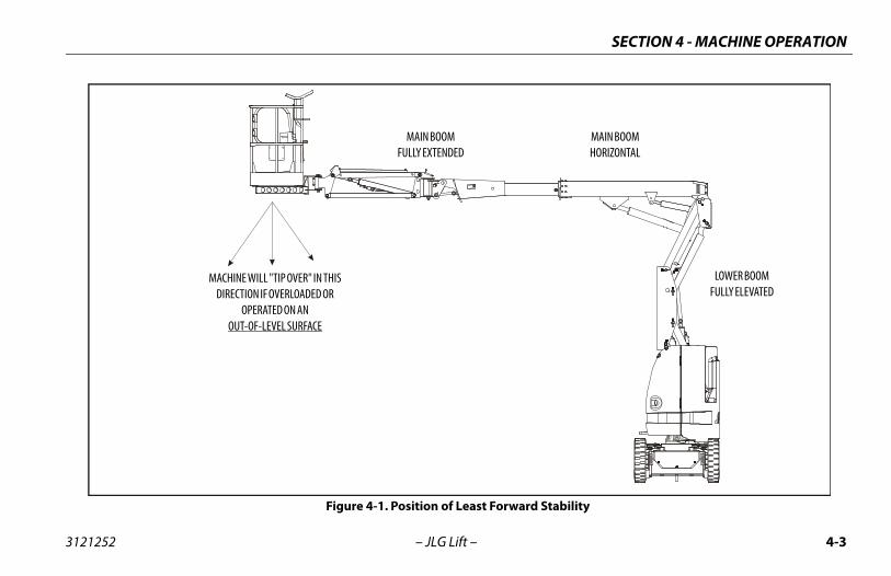
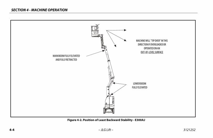
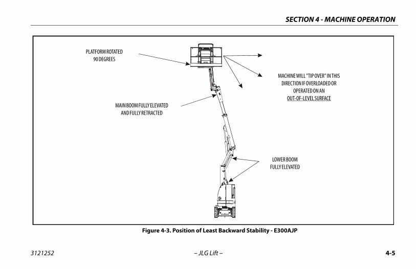
bility is based on two (2) conditions which are calledand BACKWARD stability. The machine’s position ofARD stability is shown in Figure 4-1., and its positionKWARD stability is shown in Figure 4-2. and Figure 4-
OR BACKWARD TIPPING, DO NOT OVERLOAD MACHINE OR OPER- AN OUT-OF-LEVEL SURFACE.
– JLG Lift –
BOOM OPERATING CHARACTERISTICS AND LIMITATIONS
acities
Raising boom above horizontal with or without any load in plat-form, is based on the following criteria:
1. Machine is positioned on a smooth, firm and level surface.
2. Load is within manufacturers rated design capacity.
3. All machine systems are functioning properly.
4. Machine is as originally equipped from JLG.
StabilityMachine staFORWARD least FORWof least BAC3.
TO AVOID FORWARD ATE THE MACHINE ON
SECTION 4 - MACHINE OPERATION
4-3
Stability
LOWER BOOMFULLY ELEVATED
MAIN BOOMHORIZONTAL
3121252 – JLG Lift –
Figure 4-1. Position of Least Forward
MAIN BOOMFULLY EXTENDED
MACHINE WILL "TIP OVER" IN THISDIRECTION IF OVERLOADED OR
OPERATED ON ANOUT-OF-LEVEL SURFACE
SECTION 4 - MACHINE OPERATION
4-4 3121252
.
lity - E300AJ
LOWER BOOMFULLY ELEVATED
MACHINE WILL "TIP OVER" IN THISDIRECTION IF OVERLOADED OR
OPERATED ON ANOUT-OF-LEVEL SURFACE
– JLG Lift –
Figure 4-2. Position of Least Backward Stabi
MAIN BOOM FULLY ELEVATEDAND FULLY RETRACTED
SECTION 4 - MACHINE OPERATION
4-5
tability - E300AJP
LOWER BOOMFULLY ELEVATED
MACHINE WILL "TIP OVER" IN THISDIRECTION IF OVERLOADED OR
OPERATED ON ANOUT-OF-LEVEL SURFACE
3121252 – JLG Lift –
Figure 4-3. Position of Least Backward S
PLATFORM ROTATED90 DEGREES
MAIN BOOM FULLY ELEVATEDAND FULLY RETRACTED
SECTION 4 - MACHINE OPERATION
4-6 3121252
4.3
Pow
Pla
ion
BE DEPRESSED PRIOR TO ACTIVATING ANY FUNCTION, OTHER-L NOT OPERATE.
ecomes activated and operates the desired functionergency Stop switch is pulled out (on), the Platform/
ct switch is in the appropriate position and the Foot-pressed.
CTION NECESSITATES UNSCHEDULED SHUTDOWN, DETERMINEUSE BEFORE RESUMING ANY OPERATION.
MERGENCY STOP SWITCH TO THE ‘OFF’ POSITION (PUSHED IN)OT IN USE.
– JLG Lift –
MOTOR OPERATION
er/Emergency Stop Switch
This red, mushroom-shaped switch provides battery power to thePlatform/Ground Select switch, when pulled out (on), for allmachine functions. The switch should be pushed in (off ) whenrecharging the batteries or parking the machine overnight.
tform/Ground Select Switch
The Platform/Ground Select switch functions to direct batterypower to the desired control station when the POWER/EMER-GENCY STOP switch is pulled out (on). With the switch in theGROUND position, battery power is supplied to the ground con-trol station. When the switch is in the PLATFORM position, batterypower is supplied to the platform control station.
The key is removable in the platform position on CE machines.The key must be available to ground personnel in the event of anemergency.
Motor Activat
FOOTSWITCH MUST WISE FUNCTION WIL
The motor bwhen the EmGround seleswitch is de
IF A MOTOR MALFUNAND CORRECT THE CA
ALWAYS POSITION EWHEN MACHINE IS N
SECTION 4 - MACHINE OPERATION
4-7
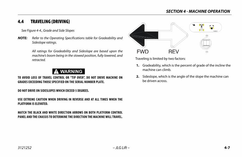
ng is limited by two factors:
adeability, which is the percent of grade of the incline the achine can climb.
deslope, which is the angle of the slope the machine can driven across.
3121252 – JLG Lift –
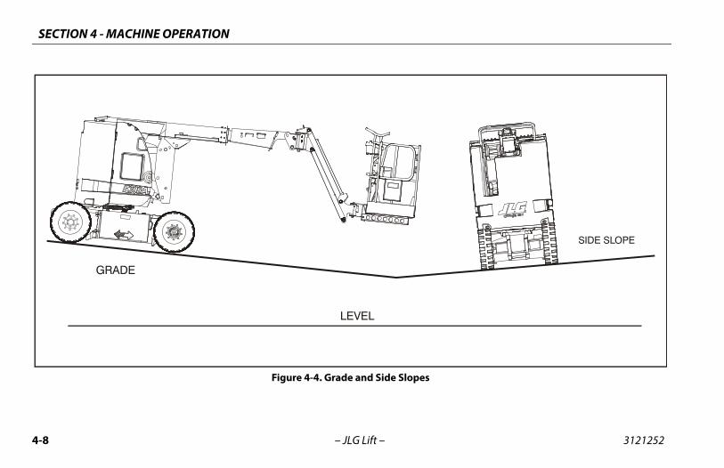
4.4 TRAVELING (DRIVING)
See Figure 4-4., Grade and Side Slopes
NOTE: Refer to the Operating Specifications table for Gradeability andSideslope ratings.
All ratings for Gradeability and Sideslope are based upon themachine’s boom being in the stowed position, fully lowered, andretracted.
TO AVOID LOSS OF TRAVEL CONTROL OR “TIP OVER”, DO NOT DRIVE MACHINE ONGRADES EXCEEDING THOSE SPECIFIED ON THE SERIAL NUMBER PLATE.
DO NOT DRIVE ON SIDESLOPES WHICH EXCEED 5 DEGREES.
USE EXTREME CAUTION WHEN DRIVING IN REVERSE AND AT ALL TIMES WHEN THEPLATFORM IS ELEVATED.
MATCH THE BLACK AND WHITE DIRECTION ARROWS ON BOTH PLATFORM CONTROLPANEL AND THE CHASSIS TO DETERMINE THE DIRECTION THE MACHINE WILL TRAVEL.
Traveli
1. Grm
2. Sibe
SECTION 4 - MACHINE OPERATION
4-8 3121252
SIDE SLOPE
– JLG Lift –
GRADE
LEVEL
Figure 4-4. Grade and Side Slopes
SECTION 4 - MACHINE OPERATION
4-9
ERINGn thumb switch on Drive/Steer controller to RIGHT forg right, or to LEFT for steering left.
TFORM
PLATFORM LEVELING OVERRIDE FUNCTION FOR SLIGHT LEVELING OF. INCORRECT USE COULD CAUSE THE LOAD/OCCUPANTS TO SHIFT ORTO DO SO COULD RESULT IN DEATH OR SERIOUS INJURY.
evel Adjustmentually Level Up or Down - Position the Platform/Level con-
itch Up or Down and hold until the desired platform posi-obtained.
otationte the platform to the left or right, use the Platform Rotatel switch to select the direction and hold until desired posi-reached.
3121252 – JLG Lift –
Traveling Forward and Reverse1. At Platform Controls, pull out Emergency Stop switch and
activate footswitch.
2. Position Drive controller to FORWARD or REVERSE as desired.
This machine is equipped with a Drive Orientation Indicator. Theyellow light on the platform control console indicates that theboom is swung beyond the rear drive tires and the machine mayDrive/Steer in the opposite direction from the movement of thecontrols. If the indicator is illuminated, operate the Drive functionin the following manner:
1. Match the black and white direction arrows on both plat-form control panel and the chassis to determine the direc-tion the machine will travel.
2. Push and release the Drive Orientation Override switch. Within 3 seconds, slowly move the Drive control toward the arrow matching the intended direction of machine travel. The indicator light will flash during the 3 second interval until the drive function is selected.
4.5 STEPositiosteerin
4.6 PLA
ONLY USE THE THE PLATFORMFALL. FAILURE
Platform LTo mantrol swtion is
Platform RTo rotacontrotion is
SECTION 4 - MACHINE OPERATION
4-1 3121252
4.7
A REWHEABOV
DO NALARCHASOR D
TO AABOVMACH
TRAVSLOP
JURY, DO NOT OPERATE MACHINERY IF ANY CONTROL LEVER ORTROLLING PLATFORM MOVEMENT DOES NOT RETURN TO THESITION WHEN RELEASED.
N AND INJURY IF PLATFORM DOES NOT STOP WHEN A CONTROL RELEASED, REMOVE FOOT FROM FOOTSWITCH OR USE EMER-
TO STOP THE MACHINE.
0 – JLG Lift –
BOOM
D TILT WARNING LIGHT IS LOCATED ON THE CONTROL CONSOLE WHICH LIGHTSN THE CHASSIS IS ON AN EXCESSIVE SLOPE. DO NOT SWING OR RAISE BOOME HORIZONTAL WHEN LIGHT IS LIT.
OT DEPEND ON TILT ALARM AS A LEVEL INDICATOR FOR THE CHASSIS. TILTM INDICATES CHASSIS IS ON AN EXCESSIVE SLOPE (5 DEGREE OR GREATER).SIS MUST BE LEVEL BEFORE SWINGING, OR RAISING BOOM ABOVE HORIZONTAL
RIVING WITH THE BOOM ELEVATED.
VOID TIP OVER IF RED TILT WARNING LIGHT LIGHTS WHEN BOOM IS RAISEDE HORIZONTAL, LOWER PLATFORM TO GROUND LEVEL. THEN REPOSITIONINE SO THAT CHASSIS IS LEVEL BEFORE RAISING BOOM.
ELING WITH BOOM BELOW HORIZONTAL IS PERMITTED ON GRADES AND SIDEES SPECIFIED ON SERIAL NAMEPLATE ON THE FRAME.
TO AVOID SERIOUS INTOGGLE SWITCH CON‘OFF’ OR NEUTRAL PO
TO AVOID A COLLISIOSWITCH OR LEVER ISGENCY STOP SWITCH
SECTION 4 - MACHINE OPERATION
4-11
CTION SPEED CONTROLntrol affects the speed of boom functions and platform
Lift, Telescope, and Swing. When in the fully counterclock-sition, Drive is placed in creep speed.
3121252 – JLG Lift –
Swinging the Boom
To swing boom, use Swing control to select Right or Left direc-tion.
Raising and Lowering the Upper BoomTo raise or lower the Upper Boom, position Upper Boom Liftswitch to Up or Down until desired height is reached.
4.8 FUNThis corotate wise po
SECTION 4 - MACHINE OPERATION
4-1 3121252
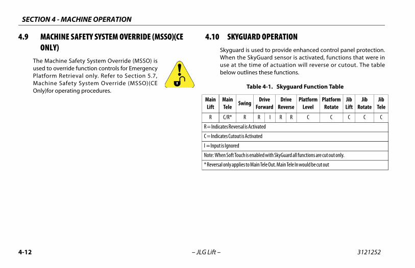
4.9 RD OPERATION used to provide enhanced control panel protection.kyGuard sensor is activated, functions that were in
time of actuation will reverse or cutout. The tablenes these functions.
able 4-1. Skyguard Function Table
gDrive
ForwardDrive
ReversePlatform
LevelPlatform
RotateJibLift
JibRotate
JibTele
R I R R C C C C C
ctivated
tivated
enabled with SkyGuard all functions are cut out only.
Main Tele Out. Main Tele In would be cut out
2 – JLG Lift –
MACHINE SAFETY SYSTEM OVERRIDE (MSSO)(CE ONLY)
The Machine Safety System Override (MSSO) isused to override function controls for EmergencyPlatform Retrieval only. Refer to Section 5.7,Machine Safety System Override (MSSO)(CEOnly)for operating procedures.
4.10 SKYGUASkyguard isWhen the Suse at the below outli
T
MainLift
MainTele
Swin
R C/R* R
R = Indicates Reversal is A
C = Indicates Cutout is Ac
I = Input is Ignored
Note: When Soft Touch is
* Reversal only applies to
SECTION 4 - MACHINE OPERATION
4-13
ut down Emergency Stop at Platform Controls.
ut down Emergency Stop at Ground Controls. Positionatform/Ground Select switch to center OFF.
necessary, cover Platform Controls to protect instructionacards, warning decals, and operating controls from hos-e environment.
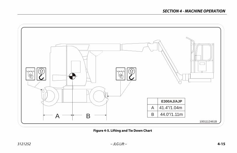
TING AND TIE DOWNure 4-5.)
fer to the Serial Number Plate, refer to the Specificationsction of this manual, or weigh the individual unit to findt the Gross Vehicle Weight.
ace the boom in the stowed position.
move all loose items from the machine.
operly adjust the rigging to prevent damage to theachine and so the machine remains level.
3121252 – JLG Lift –
4.11 SHUT DOWN AND PARKNOTE: When parking battery powered units overnight, batteries should
be charged in accordance with instructions in Section 6 toensure readiness for following workday.
NOTE: Electric machines are equipped with a static strap due to staticelectricity build-ups. Strap is located under rear of machine chas-sis.
The procedures to shut down and park the machine are as fol-lows:
1. Drive machine to a reasonably well protected area.
2. Ensure boom is lowered over rear drive axle.
3. Sh
4. ShPl
5. If pltil
4.12 LIF(See Fig
Lifting1. Re
seou
2. Pl
3. Re
4. Prm
SECTION 4 - MACHINE OPERATION
4-1 3121252
Tie
WHETHE B
4 – JLG Lift –
Down
N TRANSPORTING THE MACHINE, THE BOOM MUST BE FULLY LOWERED INTOOOM REST.
1. Place the boom in the stowed position.
2. Remove all loose items from the machine.
3. Secure the chassis and the platform using straps or chains ofadequate strength.
SECTION 4 - MACHINE OPERATION
4-15
A 41.4”/1.04mB 44.0”/1.11m
E300AJ/AJP
1001112461B
Chart
3121252 – JLG Lift –
A B
Figure 4-5. Lifting and Tie Down
SECTION 4 - MACHINE OPERATION
4-1 3121252
BOTHSIDES
BOTHSIDES
BOTHSIDES
7
24
25
26
30
149
6
of 5
6 – JLG Lift –
HYD TANK VIEWINSIDE HOOD
19
28
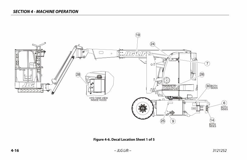
Figure 4-6. Decal Location Sheet 1
SECTION 4 - MACHINE OPERATION
4-17
46
23
1645
29
31
24
15
536
of 5
3121252 – JLG Lift –
336
14
23
24
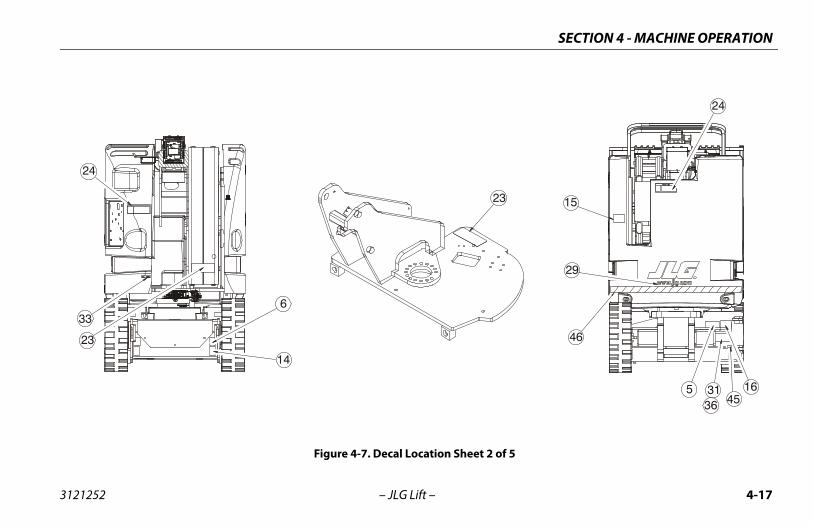
Figure 4-7. Decal Location Sheet 2
SECTION 4 - MACHINE OPERATION
4-1 3121252
34
12
3 of 5
8 – JLG Lift –
11
2232
25
25
26
9
42
40
41
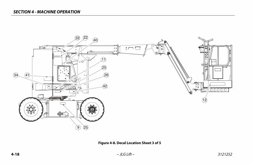
Figure 4-8. Decal Location Sheet
SECTION 4 - MACHINE OPERATION
4-19
44
46
TAIL A3
4
8
20
29
12
18
394345
235
37
137
4 of 5
3121252 – JLG Lift –
SEE DE
DETAIL A
21
20
17
23
23
33
27
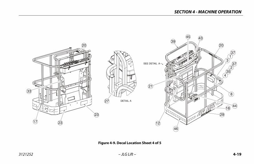
Figure 4-9. Decal Location Sheet
SECTION 4 - MACHINE OPERATION
4-2 3121252
LOCATE ON SIDEOF CONTROL BOX.
9
38
5
0 – JLG Lift –
BOTHSIDES
13
13
30
10
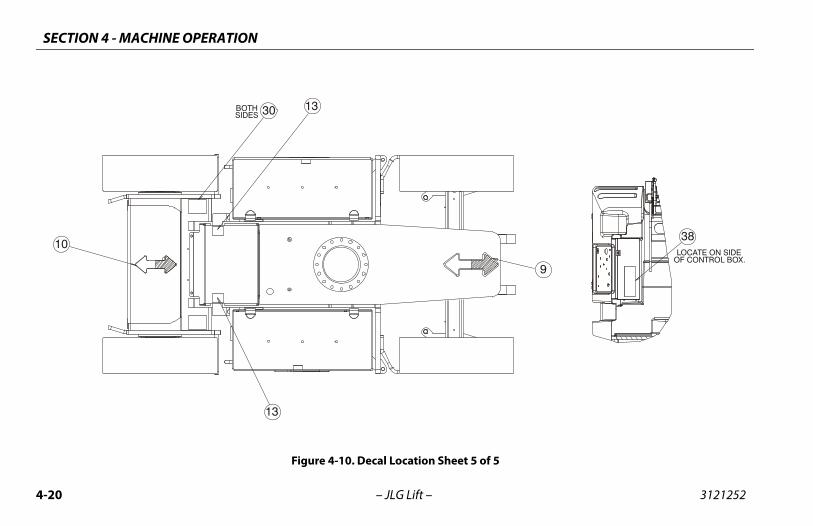
Figure 4-10. Decal Location Sheet 5 of
SECTION 4 - MACHINE OPERATION
4-21
ish828-B
French1001110829-C
Chinese1001110830-B
Portuguese1001110831-B
- - - - - -
- - - - - -
- - - - - -
- - - - - -
84 1700584 1700584 1700584
00 1701500 1701500 1701500
04 1701504 1701504 1701504
09 1701509 1701509 1701509
29 1701529 1701529 1701529
42 1701642 1701642 1701642
44 1701644 1701644 1701644
56 1707055 1707060 1707134
55 1702155 1702155 1702155
00 1702300 1702300 1702300
3171 1001113169 1001113168 1001113170
31 1702631 1702631 1702631
- - - - - -
- - - - - -
- - - - - -
3121252 – JLG Lift –
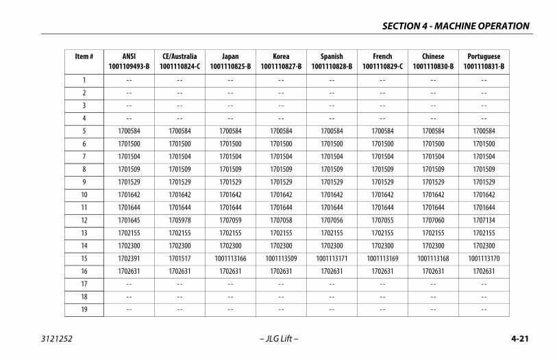
Item # ANSI1001109493-B
CE/Australia1001110824-C
Japan1001110825-B
Korea1001110827-B
Span1001110
1 - - - - - - - - - -
2 - - - - - - - - - -
3 - - - - - - - - - -
4 - - - - - - - - - -
5 1700584 1700584 1700584 1700584 17005
6 1701500 1701500 1701500 1701500 17015
7 1701504 1701504 1701504 1701504 17015
8 1701509 1701509 1701509 1701509 17015
9 1701529 1701529 1701529 1701529 17015
10 1701642 1701642 1701642 1701642 17016
11 1701644 1701644 1701644 1701644 17016
12 1701645 1705978 1707059 1707058 17070
13 1702155 1702155 1702155 1702155 17021
14 1702300 1702300 1702300 1702300 17023
15 1702391 1701517 1001113166 1001113509 100111
16 1702631 1702631 1702631 1702631 17026
17 - - - - - - - - - -
18 - - - - - - - - - -
19 - - - - - - - - - -
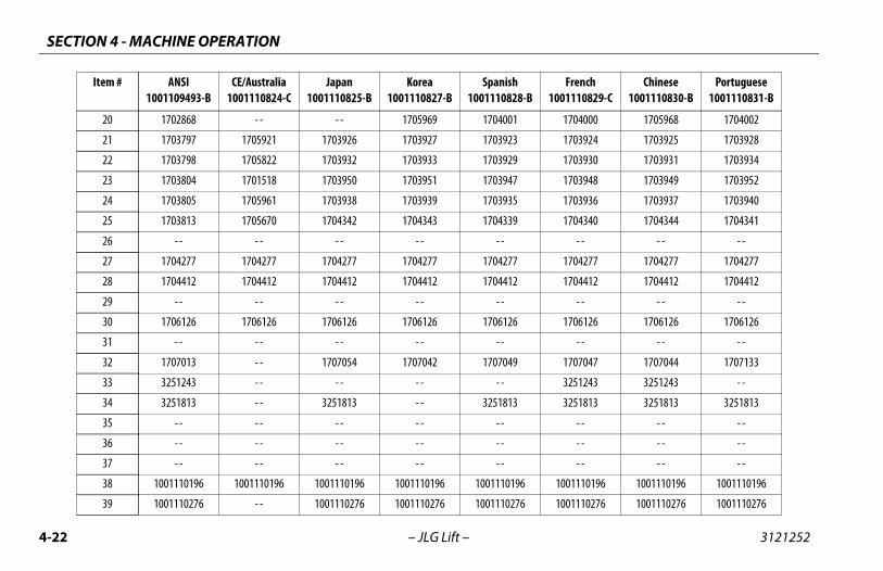
SECTION 4 - MACHINE OPERATION
4-2 3121252
1704000 1705968 1704002
1703924 1703925 1703928
1703930 1703931 1703934
1703948 1703949 1703952
1703936 1703937 1703940
1704340 1704344 1704341
- - - - - -
1704277 1704277 1704277
1704412 1704412 1704412
- - - - - -
1706126 1706126 1706126
- - - - - -
1707047 1707044 1707133
3251243 3251243 - -
3251813 3251813 3251813
- - - - - -
- - - - - -
- - - - - -
1001110196 1001110196 1001110196
1001110276 1001110276 1001110276
French1001110829-C
Chinese1001110830-B
Portuguese1001110831-B
2 – JLG Lift –
20 1702868 - - - - 1705969 1704001
21 1703797 1705921 1703926 1703927 1703923
22 1703798 1705822 1703932 1703933 1703929
23 1703804 1701518 1703950 1703951 1703947
24 1703805 1705961 1703938 1703939 1703935
25 1703813 1705670 1704342 1704343 1704339
26 - - - - - - - - - -
27 1704277 1704277 1704277 1704277 1704277
28 1704412 1704412 1704412 1704412 1704412
29 - - - - - - - - - -
30 1706126 1706126 1706126 1706126 1706126
31 - - - - - - - - - -
32 1707013 - - 1707054 1707042 1707049
33 3251243 - - - - - - - -
34 3251813 - - 3251813 - - 3251813
35 - - - - - - - - - -
36 - - - - - - - - - -
37 - - - - - - - - - -
38 1001110196 1001110196 1001110196 1001110196 1001110196
39 1001110276 - - 1001110276 1001110276 1001110276
Item # ANSI1001109493-B
CE/Australia1001110824-C
Japan1001110825-B
Korea1001110827-B
Spanish1001110828-B
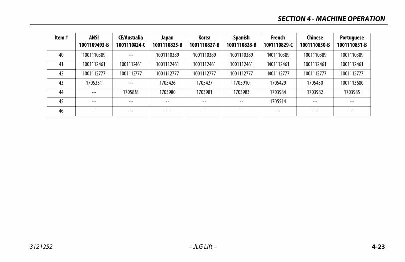
SECTION 4 - MACHINE OPERATION
4-23
0389 1001110389 1001110389 1001110389
2461 1001112461 1001112461 1001112461
2777 1001112777 1001112777 1001112777
10 1705429 1705430 1001113680
83 1703984 1703982 1703985
1705514 - - - -
- - - - - -
ish828-B
French1001110829-C
Chinese1001110830-B
Portuguese1001110831-B
3121252 – JLG Lift –
40 1001110389 - - 1001110389 1001110389 100111
41 1001112461 1001112461 1001112461 1001112461 100111
42 1001112777 1001112777 1001112777 1001112777 100111
43 1705351 - - 1705426 1705427 17059
44 - - 1705828 1703980 1703981 17039
45 - - - - - - - - - -
46 - - - - - - - - - -
Item # ANSI1001109493-B
CE/Australia1001110824-C
Japan1001110825-B
Korea1001110827-B
Span1001110
SECTION 4 - MACHINE OPERATION
4-2 3121252
4 – JLG Lift –NOTES:
SECTION 5 - EMERGENCY PROCEDURES
5-1
OCEDURES
NY INCIDENT, THOROUGHLY INSPECT THE MACHINE AND TEST ALLST FROM THE GROUND CONTROLS, THEN FROM THE PLATFORM CON-
LIFT ABOVE 3 M (10 FT.) UNTIL YOU ARE SURE THAT ALL DAMAGE HASD, IF REQUIRED, AND THAT ALL CONTROLS ARE OPERATING COR-
ERGENCY OPERATION
nable to Control MachinePLATFORM OPERATOR IS PINNED, TRAPPED OR UNABLE TOTE OR CONTROL MACHINE:
ther personnel should operate the machine from ground ntrols only as required.
ther qualified personnel on the platform may use the plat-rm controls. DO NOT CONTINUE OPERATION IF CONTROLS
NOT FUNCTION PROPERLY.
anes, forklift trucks or other equipment can be used to sta-lize motion of the machine.
3121252 – JLG Lift –
SECTION 5. EMERGENC Y PR
5.1 GENERALThis section explains the steps to be taken in case of an emer-gency situation while operating.
5.2 INCIDENT NOTIFICATIONJLG Industries, Inc. must be notified immediately of any incidentinvolving a JLG product. Even if no injury or property damage isevident, the factory should be contacted by telephone and pro-vided with all necessary details.
In USA:JLG Phone: 877-JLG-SAFE (554-7233) (8am till 4:45pm EST)
Outside USA: 240-420-2661
E-mail:
Failure to notify the manufacturer of an incident involving a JLGIndustries product within 48 hours of such an occurrence mayvoid any warranty consideration on that particular machine.
FOLLOWING AFUNCTIONS FIRTROLS. DO NOTBEEN REPAIRERECTLY.
5.3 EM
Operator UIF THE OPERA
1. Oco
2. OfoDO
3. Crbi
SECTION 5 - EMERGENCY PROCEDURES
5-2 3121252
Pla
5.4
THE TOW
age the mechanical release on both drive hubs bying, completely reversing, and tightening the twon each hub.
e chocks from wheels as desired.
L DESCENT SYSTEM5-1., Manual Descent Location)
scent system is used, in the event of total power fail-he key is not accessible to the ground personnel, tor and lower booms using gravity. The jib lift cylinder
ed down. To operate the manual descent system, pro-:
the manual descent knob on the boom functionush the knob in to lower the tower and pull the knob
lower the main boom. The knob must be held in placeform the lowering function; it is spring loaded toto center when released. Install handle into manualt pump and lower the selected cylinders by pumpingdle until the boom is completely lowered.
ped with a jib, locate the split ring on the boom func-lve. Push the split ring in to lower the jib or pull theg out to raise the jib by pumping the handle until it istely lowered or raised. Stow the handle in bracket
ed.
– JLG Lift –
tform or Boom Caught OverheadIf the platform or boom becomes jammed or snagged in over-head structures or equipment, rescue platform occupants prior tofreeing the machine.
EMERGENCY TOWING PROCEDURESTowing this machine is prohibited. However, provisions for mov-ing the machine have been incorporated. The following proce-dures are to be used ONLY for emergency movement to asuitable maintenance area.
ALLOWABLE TOWING SPEED IS 1.9 MPH (3 KPH). THE MAXIMUM ALLOWABLEING DISTANCE IS 0.6 MILES (1 KM).
1. Chock wheels securely.
2. Engage the mechanical release on both drive hubs by loos-ening, completely reversing, and tightening the two bolts oneach hub.
3. Connect suitable equipment, remove chocks, and movemachine.
After moving machine, complete the following procedure:
1. Position machine on a firm level surface.
2. Chock wheels securely.
3. Disengloosenbolts o
4. Remov
5.5 MANUA(See Figure
The manual deure or in case tlower the uppemust be pumpceed as follows
1. Locatevalve. Pout to to perreturn descenthe han
2. If equiption vasplit rincompleprovid
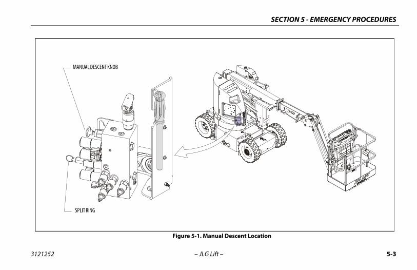
SECTION 5 - EMERGENCY PROCEDURES
5-3
ocation
3121252 – JLG Lift –
Figure 5-1. Manual Descent L
SPLIT RING
MANUAL DESCENT KNOB
SECTION 5 - EMERGENCY PROCEDURES
5-4 3121252
5.6
Thtupm
5.7
NOT
tional checks of the MSSO system are necessary. The JLGsystem will set a Diagnostic Trouble Code if the control faulty.
he MSSO:
he ground control console, place the Platform/ Select switch in the Ground position.
t the Power/Emergency Stop control.
e engine.
nd hold the MSSO switch and the control switch for ired function.
– JLG Lift –
MANUAL SWING OVERRIDE
e manual swing override is used to manually swing the boom andrntable assembly in the event of a total power failure when the
latform is positioned over a structure or obstacle. To operate theanual swing override, proceed as follows:
1. Using a 7/8 inch socket and ratchet wrench, locate nut onswing worm gear on left side of machine.
2. Install wrench on nut and ratchet in the direction desired.
MACHINE SAFETY SYSTEM OVERRIDE (MSSO)(CE ONLY)
The Machine Safety System Override (MSSO) isonly to be used to retrieve an operator that ispinned, trapped, or unable to operate themachine and function controls are locked outfrom the platform due to a platform overload sit-uation.
E: If the MSSO functionality is used, the fault indicator will flashand a fault code is set in the JLG Control System which must bereset by a qualified JLG Service Technician.
NOTE: No funcControl switch is
To operate t
1. From tGround
2. Pull ou
3. Start th
4. Press athe des
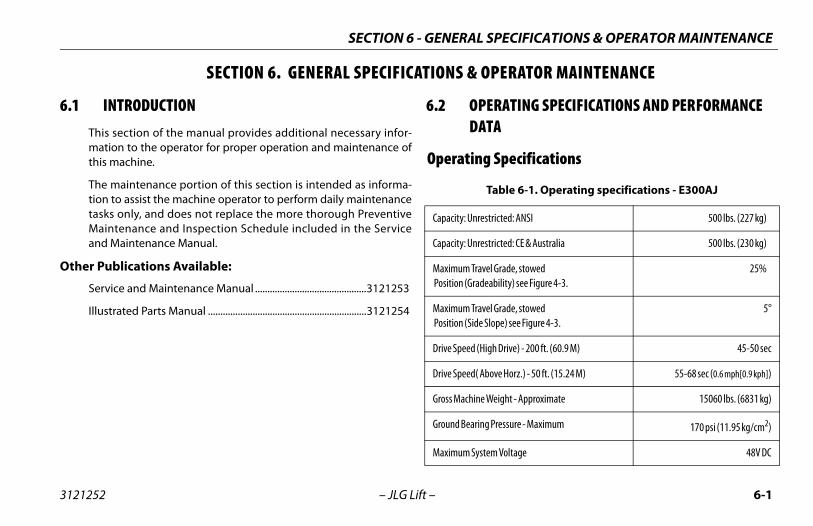
PECIFICATIONS & OPERATOR MAINTENANCE
6-1
PERATOR MAINTENANCE
RATING SPECIFICATIONS AND PERFORMANCE A
Specifications
able 6-1. Operating specifications - E300AJ
tricted: ANSI 500 lbs. (227 kg)
tricted: CE & Australia 500 lbs. (230 kg)
l Grade, stowedability) see Figure 4-3.
25%
l Grade, stowedlope) see Figure 4-3.
5°
gh Drive) - 200 ft. (60.9 M) 45-50 sec
ove Horz.) - 50 ft. (15.24 M) 55-68 sec (0.6 mph[0.9 kph])
eight - Approximate 15060 lbs. (6831 kg)
Pressure - Maximum 170 psi (11.95 kg/cm2)
m Voltage 48V DC
SECTION 6 - GENERAL S
3121252 – JLG Lift –
SECTION 6. GENERAL SPECIFICATIONS & O
6.1 INTRODUCTIONThis section of the manual provides additional necessary infor-mation to the operator for proper operation and maintenance ofthis machine.
The maintenance portion of this section is intended as informa-tion to assist the machine operator to perform daily maintenancetasks only, and does not replace the more thorough PreventiveMaintenance and Inspection Schedule included in the Serviceand Maintenance Manual.
Other Publications Available:
Service and Maintenance Manual .............................................3121253
Illustrated Parts Manual ................................................................3121254
6.2 OPEDAT
Operating
T
Capacity: Unres
Capacity: Unres
Maximum Trave Position (Grade
Maximum Trave Position (Side S
Drive Speed (Hi
Drive Speed( Ab
Gross Machine W
Ground Bearing
Maximum Syste
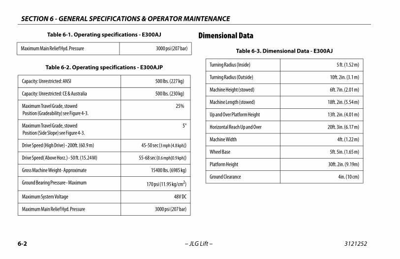
SECTION 6 - GENERAL SPECIFICATIONS & OPERATOR MAINTENANCE
6-2 3121252
ataMax
Cap
Cap
Ma Po
Ma Po
Dri
Dri
Gro
Gro
Ma
Ma
ble 6-3. Dimensional Data - E300AJ
side) 5 ft. (1.52 m)
utside) 10ft. 2in. (3.1 m)
stowed) 6ft. 7in. (2.01 m)
stowed) 18ft. 2in. (5.54 m)
orm Height 13ft. 2in. (4.01 m)
Up and Over 20ft. 3in. (6.17 m)
4ft. (1.22 m)
5ft. 5in. (1.65 m)
30ft. 2in. (9.19m)
4in. (10 cm)
– JLG Lift –
Dimensional Dimum Main Relief Hyd. Pressure 3000 psi (207 bar)
Table 6-2. Operating specifications - E300AJP
acity: Unrestricted: ANSI 500 lbs. (227 kg)
acity: Unrestricted: CE & Australia 500 lbs. (230 kg)
ximum Travel Grade, stowedsition (Gradeability) see Figure 4-3.
25%
ximum Travel Grade, stowedsition (Side Slope) see Figure 4-3.
5°
ve Speed (High Drive) - 200ft. (60.9 m) 45-50 sec (3 mph [4.8 kph])
ve Speed( Above Horz.) - 50 ft. (15.24 M) 55-68 sec (0.6 mph[0.9 kph])
ss Machine Weight- Approximate 15400 lbs. (6985 kg)
und Bearing Pressure - Maximum 170 psi (11.95 kg/cm2)
ximum System Voltage 48V DC
ximum Main Relief Hyd. Pressure 3000 psi (207 bar)
Table 6-1. Operating specifications - E300AJ
Ta
Turning Radius (In
Turning Radius (O
Machine Height (
Machine Length (
Up and Over Platf
Horizontal Reach
Machine Width
Wheel Base
Platform Height
Ground Clearance
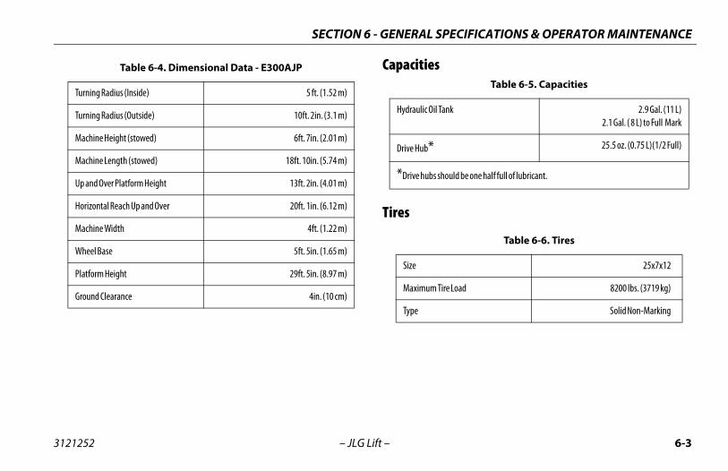
PECIFICATIONS & OPERATOR MAINTENANCE
6-3
Table 6-5. Capacities
Tank 2.9 Gal. (11 L)2.1 Gal. ( 8 L) to Full Mark
25.5 oz. (0.75 L)(1/2 Full)
should be one half full of lubricant.
Table 6-6. Tires
25x7x12
Tire Load 8200 lbs. (3719 kg)
Solid Non-Marking
SECTION 6 - GENERAL S
3121252 – JLG Lift –
Capacities
Tires
Table 6-4. Dimensional Data - E300AJP
Turning Radius (Inside) 5 ft. (1.52 m)
Turning Radius (Outside) 10ft. 2in. (3.1 m)
Machine Height (stowed) 6ft. 7in. (2.01 m)
Machine Length (stowed) 18ft. 10in. (5.74 m)
Up and Over Platform Height 13ft. 2in. (4.01 m)
Horizontal Reach Up and Over 20ft. 1in. (6.12 m)
Machine Width 4ft. (1.22 m)
Wheel Base 5ft. 5in. (1.65 m)
Platform Height 29ft. 5in. (8.97 m)
Ground Clearance 4in. (10 cm)
Hydraulic Oil
Drive Hub*
*Drive hubs
Size
Maximum
Type
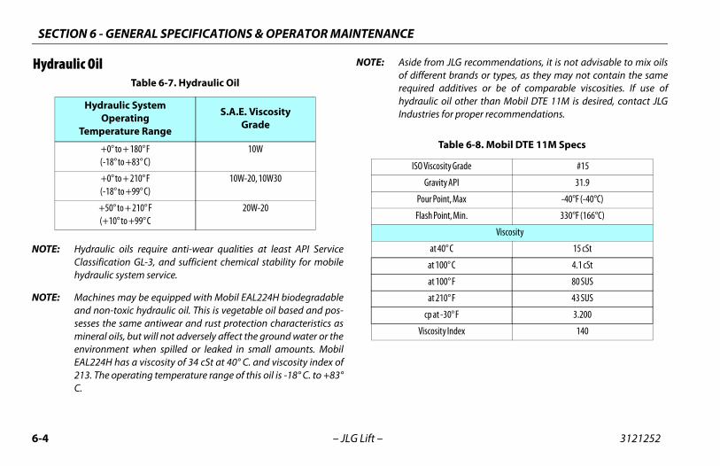
SECTION 6 - GENERAL SPECIFICATIONS & OPERATOR MAINTENANCE
6-4 3121252
Hyd
NOT
NOT
m JLG recommendations, it is not advisable to mix oilsent brands or types, as they may not contain the same additives or be of comparable viscosities. If use ofc oil other than Mobil DTE 11M is desired, contact JLGs for proper recommendations.
Table 6-8. Mobil DTE 11M Specs
cosity Grade #15
avity API 31.9
Point, Max -40°F (-40°C)
Point, Min. 330°F (166°C)
Viscosity
t 40° C 15 cSt
t 100° C 4.1 cSt
t 100° F 80 SUS
t 210° F 43 SUS
at -30° F 3.200
sity Index 140
– JLG Lift –
raulic Oil
E: Hydraulic oils require anti-wear qualities at least API ServiceClassification GL-3, and sufficient chemical stability for mobilehydraulic system service.
E: Machines may be equipped with Mobil EAL224H biodegradableand non-toxic hydraulic oil. This is vegetable oil based and pos-sesses the same antiwear and rust protection characteristics asmineral oils, but will not adversely affect the ground water or theenvironment when spilled or leaked in small amounts. MobilEAL224H has a viscosity of 34 cSt at 40° C. and viscosity index of213. The operating temperature range of this oil is -18° C. to +83°C.
NOTE: Aside froof differrequiredhydrauliIndustrie
Table 6-7. Hydraulic Oil
Hydraulic SystemOperating
Temperature Range
S.A.E. ViscosityGrade
+0° to + 180° F(-18° to +83° C)
10W
+0° to + 210° F(-18° to +99° C)
10W-20, 10W30
+50° to + 210° F(+10° to +99° C
20W-20
ISO Vis
Gr
Pour
Flash
a
a
a
a
cp
Visco
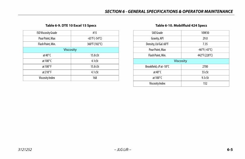
PECIFICATIONS & OPERATOR MAINTENANCE
6-5
Table 6-10. Mobilfluid 424 Specs
SAE Grade 10W30
Gravity, API 29.0
ensity, Lb/Gal. 60°F 7.35
Pour Point, Max -46°F (-43°C)
Flash Point, Min. 442°F (228°C)
Viscosity
rookfield, cP at -18°C 2700
at 40° C 55 cSt
at 100° C 9.3 cSt
Viscosity Index 152
SECTION 6 - GENERAL S
3121252 – JLG Lift –
Table 6-9. DTE 10 Excel 15 Specs
ISO Viscosity Grade #15
Pour Point, Max -65°F (-54°C)
Flash Point, Min. 360°F (182°C)
Viscosity
at 40° C 15.8 cSt
at 100° C 4.1cSt
at 100° F 15.8 cSt
at 210° F 4.1 cSt
Viscosity Index 168
D
B
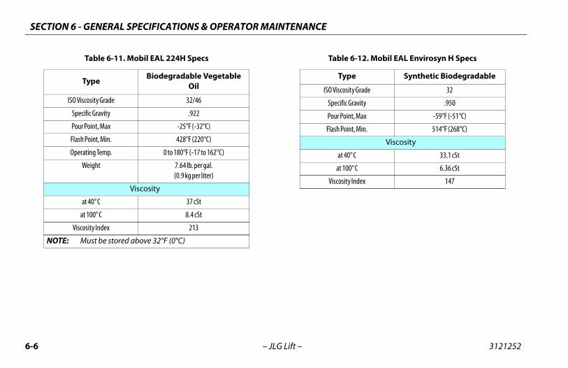
SECTION 6 - GENERAL SPECIFICATIONS & OPERATOR MAINTENANCE
6-6 3121252
le 6-12. Mobil EAL Envirosyn H Specs
ype Synthetic Biodegradable
osity Grade 32
fic Gravity .950
oint, Max -59°F (-51°C)
Point, Min. 514°F (268°C)
Viscosity
t 40° C 33.1 cSt
100° C 6.36 cSt
sity Index 147
– JLG Lift –
Table 6-11. Mobil EAL 224H Specs
Type Biodegradable Vegetable Oil
ISO Viscosity Grade 32/46
Specific Gravity .922
Pour Point, Max -25°F (-32°C)
Flash Point, Min. 428°F (220°C)
Operating Temp. 0 to 180°F (-17 to 162°C)
Weight 7.64 lb. per gal.(0.9 kg per liter)
Viscosity
at 40° C 37 cSt
at 100° C 8.4 cSt
Viscosity Index 213
NOTE: Must be stored above 32°F (0°C)
Tab
T
ISO Visc
Speci
Pour P
Flash
a
at
Visco
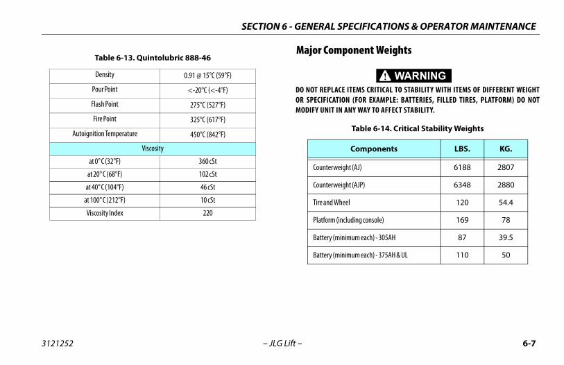
PECIFICATIONS & OPERATOR MAINTENANCE
6-7
ponent Weights
CE ITEMS CRITICAL TO STABILITY WITH ITEMS OF DIFFERENT WEIGHTION (FOR EXAMPLE: BATTERIES, FILLED TIRES, PLATFORM) DO NOTN ANY WAY TO AFFECT STABILITY.
Table 6-14. Critical Stability Weights
Components LBS. KG.
eight (AJ) 6188 2807
eight (AJP) 6348 2880
heel 120 54.4
including console) 169 78
inimum each) - 305AH 87 39.5
inimum each) - 375AH & UL 110 50
SECTION 6 - GENERAL S
3121252 – JLG Lift –
Major Com
DO NOT REPLAOR SPECIFICATMODIFY UNIT I
Table 6-13. Quintolubric 888-46
Density 0.91 @ 15°C (59°F)
Pour Point <-20°C (<-4°F)
Flash Point 275°C (527°F)
Fire Point 325°C (617°F)
Autoignition Temperature 450°C (842°F)
Viscosity
at 0° C (32°F) 360 cSt
at 20° C (68°F) 102 cSt
at 40° C (104°F) 46 cSt
at 100° C (212°F) 10 cSt
Viscosity Index 220
Counterw
Counterw
Tire and W
Platform (
Battery (m
Battery (m
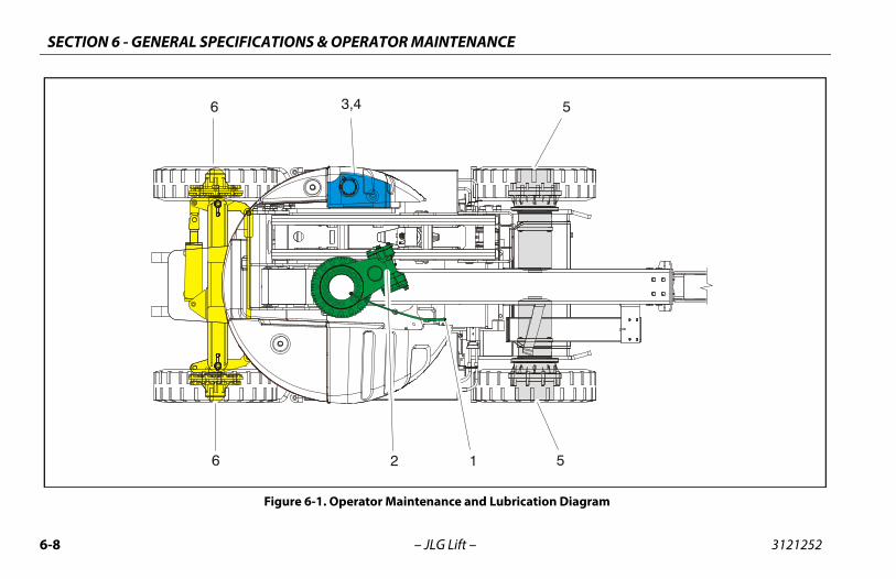
SECTION 6 - GENERAL SPECIFICATIONS & OPERATOR MAINTENANCE
6-8 3121252
5
5
ion Diagram
– JLG Lift –
1
6 3,4
26
Figure 6-1. Operator Maintenance and Lubricat
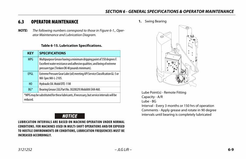
PECIFICATIONS & OPERATOR MAINTENANCE
6-9
ing Bearing
e Point(s) - Remote Fittingacity - A/Re - BGrval - Every 3 months or 150 hrs of operationments - Apply grease and rotate in 90 degree
rvals until bearing is completely lubricated
SECTION 6 - GENERAL S
3121252 – JLG Lift –
6.3 OPERATOR MAINTENANCE
NOTE: The following numbers correspond to those in Figure 6-1., Oper-ator Maintenance and Lubrication Diagram.
LUBRICATION INTERVALS ARE BASED ON MACHINE OPERATION UNDER NORMALCONDITIONS. FOR MACHINES USED IN MULTI-SHIFT OPERATIONS AND/OR EXPOSEDTO HOSTILE ENVIRONMENTS OR CONDITIONS, LUBRICATION FREQUENCIES MUST BEINCREASED ACCORDINGLY.
1. Sw
LubCapLubInteCominte
Table 6-15. Lubrication Specifications.
KEY SPECIFICATIONS
MPG Multipurpose Grease having a minimum dripping point of 350 degrees F. Excellent water resistance and adhesive qualities; and being of extreme pressure type (Timken OK 40 pounds minimum).
EPGL Extreme Pressure Gear Lube (oil) meeting API Service Classification GL-5 or Mil-Spec Mil-L-2105.
HO Hydraulic Oil. Mobil DTE-11M
BG* Bearing Grease (JLG Part No. 3020029) Mobilith SHA 460.
*MPG may be substituted for these lubricants, if necessary, but service intervals will be reduced.
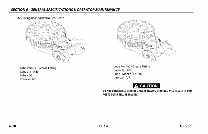
SECTION 6 - GENERAL SPECIFICATIONS & OPERATOR MAINTENANCE
6-1 3121252
nt(s) - Grease Fitting - A/Robile SHC 007 A/R
E BEARINGS. OVERGREASING BEARINGS WILL RESULT IN DAM-N HOUSING.
0 – JLG Lift –
2. Swing Bearing/Worm Gear Teeth
Lube Point(s) - Grease FittingCapacity - A/RLube - BGInterval - A/R
Lube PoiCapacityLube - MInterval -
DO NOT OVERGREASAGE TO OUTER SEAL I
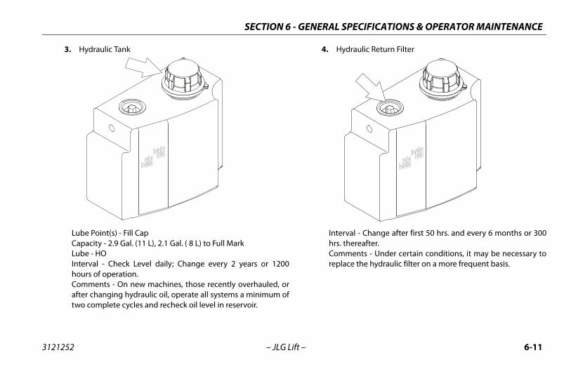
PECIFICATIONS & OPERATOR MAINTENANCE
6-11
draulic Return Filter
rval - Change after first 50 hrs. and every 6 months or 300thereafter.ments - Under certain conditions, it may be necessary to
ace the hydraulic filter on a more frequent basis.
SECTION 6 - GENERAL S
3121252 – JLG Lift –
3. Hydraulic Tank
Lube Point(s) - Fill CapCapacity - 2.9 Gal. (11 L), 2.1 Gal. ( 8 L) to Full Mark Lube - HOInterval - Check Level daily; Change every 2 years or 1200hours of operation.Comments - On new machines, those recently overhauled, orafter changing hydraulic oil, operate all systems a minimum oftwo complete cycles and recheck oil level in reservoir.
4. Hy
Intehrs. Comrepl
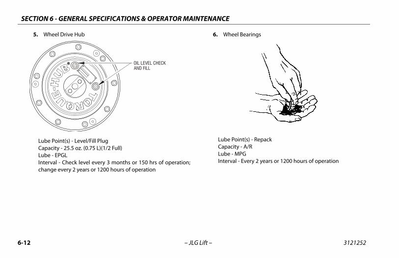
SECTION 6 - GENERAL SPECIFICATIONS & OPERATOR MAINTENANCE
6-1 3121252
Bearings
nt(s) - Repack - A/RPG Every 2 years or 1200 hours of operation
2 – JLG Lift –
5. Wheel Drive Hub
Lube Point(s) - Level/Fill PlugCapacity - 25.5 oz. (0.75 L)(1/2 Full)Lube - EPGLInterval - Check level every 3 months or 150 hrs of operation;change every 2 years or 1200 hours of operation
6. Wheel
Lube PoiCapacityLube - MInterval -
OIL LEVEL CHECKAND FILL
PECIFICATIONS & OPERATOR MAINTENANCE
6-13
move all vent caps and inspect electrolyte level of each ll. Electrolyte level should be to the ring approximately e inch from top of battery. Fill batteries with distilled
ater only. Replace and secure all vent caps.
move battery cables from each battery post one at a time, gative first. Clean cables with acid neutralizing solution
.g. baking soda and water or ammonia) and wire brush. place cables and/or cable clamp bolts as required.
ean battery post with wire brush then re-connect cable to st. Coat non-contact surfaces with mineral grease or troleum jelly.
hen all cables and terminal posts have been cleaned, sure all cables are properly positioned and do not get
nched. Close battery compartment cover.
art hydraulic system and ensure that it functions properly.
SECTION 6 - GENERAL S
3121252 – JLG Lift –
6.4 BATTERY MAINTENANCE AND CHARGING
TO AVOID INJURY FROM AN EXPLOSION, DO NOT SMOKE OR ALLOW SPARKS OR AFLAME NEAR BATTERY DURING SERVICING. ALWAYS WEAR EYE AND HAND PROTEC-TION WHEN SERVICING BATTERIES.
Battery Maintenance, Quarterly1. Open battery compartment cover to allow access to battery
terminals and vent caps.
WHEN ADDING WATER TO BATTERIES, ADD WATER UNTIL ELECTROLYTE COVERSPLATES. DO NOT CHARGE BATTERIES UNLESS ELECTROLYTE COVERS THE PLATES.
NOTE: When adding distilled water to batteries, non-metallic contain-ers and/or funnels must be used.
To avoid electrolyte overflow, add distilled water to batteriesafter charging.
When adding water to the battery, fill only to level indicated or 3/8" (9.5 mm) above separators.
2. Receonw
3. Rene(eRe
4. Clpope
5. Wenpi
6. St
SECTION 6 - GENERAL SPECIFICATIONS & OPERATOR MAINTENANCE
6-1 3121252
Bat
NOT
WHEINTOTION
low batteries to charge until 100% LED is illuminated.
atteries are completely charged, disconnect charging cable from receptacle. Store charging harness cable.
sure battery cables are properly positioned and aret pinched. Close and secure all compartment doors.
4 – JLG Lift –
tery Charging, Daily
E: To avoid excessive battery charging time, do not allow batteriesto become completely discharged.
To avoid electrolyte overflow, add distilled water to batteriesafter charging.
When adding water to the battery, fill only to level indicated or 3/8" above separators.
1. Charge batteries at the end of each work day, or when machine performance is significantly reduced due to batter-ies becoming discharged.
2. Charge batteries in accordance with the following proce-dure:
a. Open battery compartment, and battery charger com-partment covers.
N BATTERY CHARGER IS TO BE USED, CHARGING HARNESS MUST BE PLUGGED A GROUNDED RECEPTACLE. IF RECEPTACLE IS NOT GROUNDED AND A MALFUNC- SHOULD OCCUR, THE MACHINE COULD CAUSE SERIOUS ELECTRICAL SHOCK.
b. Remove charging harness cable and connect to areceptacle or the correct voltage.
c. Al
NOTE: When bharness
d. Enno
PECIFICATIONS & OPERATOR MAINTENANCE
6-15
Tire Replacement
nstalled on each product model have been designed forquirements which consist of track width, tire pressure, andity. Size changes such as rim width, center piece location,maller diameter, etc., without written factory recommen-ay result in an unsafe condition regarding stability.
tallationmely important to apply and maintain proper wheel
torque.
UST BE INSTALLED AND MAINTAINED AT THE PROPER TORQUE TOE WHEELS, BROKEN STUDS, AND POSSIBLE DANGEROUS SEPARATIONM THE AXLE. BE SURE TO USE ONLY THE NUTS MATCHED TO THE CONEWHEEL.
e lug nuts to the proper torque to prevent wheels fromose. Use a torque wrench to tighten the fasteners. If you do torque wrench, tighten the fasteners with a lug wrench,
ediately have a service garage or dealer tighten the lug proper torque. Over-tightening will result in breaking theermanently deforming the mounting stud holes in thee proper procedure for attaching wheels is as follows:
SECTION 6 - GENERAL S
3121252 – JLG Lift –
6.5 TIRES & WHEELS
Tire Replacement
JLG recommends a replacement tire be the same size, ply and brandas originally installed on the machine. Please refer to the JLG PartsManual for the part number of the approved tires for a particularmachine model. If not using a JLG approved replacement tire, werecommend that replacement tires have the following characteris-tics:
• Equal or greater ply/load rating and size of original
• Tire tread contact width equal or greater than original
• Wheel diameter, width, and offset dimensions equal to theoriginal
• Approved for the application by the tire manufacturer(including inflation pressure and maximum tire load)
Unless specifically approved by JLG Industries Inc. do not replace afoam filled or ballast filled tire assembly with a pneumatic tire. Whenselecting and installing a replacement tire, ensure that all tires areinflated to the pressure recommended by JLG. Due to size variationsbetween tire brands, both tires on the same axle should be the same.
Wheel and
The rims istability reload capaclarger or sdations, m
Wheel InsIt is extremounting
WHEEL NUTS MPREVENT LOOSOF WHEEL FROANGLE OF THE
Tighten thcoming lonot have athen immnuts to thestuds or pwheels. Th
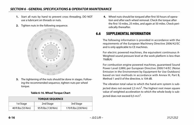
SECTION 6 - GENERAL SPECIFICATIONS & OPERATOR MAINTENANCE
6-1 3121252
nuts should be torqued after first 50 hours of opera-d after each wheel removal. Check the torque after t 10 miles, 25 miles, and again at 50 miles. Check peri-y thereafter.
MENTAL INFORMATIONng information is provided in accordance with thets of the European Machinery Directive 2006/42/EC
applicable to CE machines.
powered machines, the equivalent continuous A-ound pressure level at the work platform is less than
tion engine powered machines, guaranteed Soundl (LWA) per European Directive 2000/14/EC (Noise the Environment by Equipment for Use Outdoors)est methods in accordance with Annex III, Part B,nd 0 of the directive, is 104 dB.
n total value to which the hand-arm system is sub- not exceed 2,5 m/s2. The highest root mean squareighted acceleration to which the whole body is sub- not exceed 0,5 m/s2.
4
6 – JLG Lift –
1. Start all nuts by hand to prevent cross threading. DO NOTuse a lubricant on threads or nuts.
2. Tighten nuts in the following sequence.
3. The tightening of the nuts should be done in stages. Follow-ing the recommended sequence, tighten nuts per wheel torque.
4. Wheel tion anthe firsodicall
6.6 SUPPLEThe followirequiremenand is only
For electricWeighted s70dB(A)
For combusPower LeveEmission inbased on tMethod 1 a
The vibratiojected doesvalue of wejected does
Table 6-16. Wheel Torque Chart
TORQUE SEQUENCE
1st Stage 2nd Stage 3rd Stage
0 ft lbs (55 Nm) 95 ft lbs (130 Nm) 170 ft lbs (230 Nm)
SECTION 7 - INSPECTION AND REPAIR LOG
7-1
REPAIR LOG
ir Log
nts
3121252 – JLG Lift –
SECTION 7. INSPECTION ANDMachine Serial Number _______________________________________
Table 7-1. Inspection and Repa
Date Comme
SECTION 7 - INSPECTION AND REPAIR LOG
7-2 3121252
– JLG Lift –Table 7-1. Inspection and Repair Log
Date Comments
TRA
NSF
ER O
F O
WN
ERSH
IP
To P
rodu
ct O
wne
r:If
you
now
ow
n bu
t ARE
NO
T th
e or
igin
al p
urch
aser
of t
he p
rodu
ct c
over
ed b
y th
is m
anua
l, w
e w
ould
like
to k
now
who
you
are
. For
the
purp
ose
of re
ceiv
ing
safe
ty-r
elat
ed b
ulle
tins
, it i
s ve
ry im
port
ant t
o ke
ep JL
G In
dust
ries
, Inc
. upd
ated
wit
h th
e cu
rren
t ow
ners
hip
of a
ll JL
G
prod
ucts
. JLG
mai
ntai
ns o
wne
r inf
orm
atio
n fo
r eac
h JL
G p
rodu
ct a
nd u
ses
this
info
rmat
ion
in
case
s w
here
ow
ner n
otifi
cati
on is
nec
essa
ry.
Plea
se u
se th
is fo
rm to
pro
vide
JLG
wit
h up
date
d in
form
atio
n w
ith
rega
rd to
the
curr
ent
owne
rshi
p of
JLG
pro
duct
s. P
leas
e re
turn
com
plet
ed fo
rm to
the
JLG
Pro
duct
Saf
ety
&
Relia
bilit
y D
epar
tmen
t via
facs
imile
or m
ail t
o ad
dres
s as
spe
cifie
d be
low
.
Than
k Yo
u,Pr
oduc
t Saf
ety
& R
elia
bilit
y D
epar
tmen
tJL
G In
dust
ries
, Inc
.13
224
Foun
tain
head
Pla
zaH
ager
stow
n, M
D21
742
USA
Tele
phon
e: +
1-71
7-48
5-65
91Fa
x: +
1-30
1-74
5-37
13
NO
TE: L
ease
d or
rent
ed u
nits
sho
uld
not b
e in
clud
ed o
n th
is fo
rm.
Mfg
. Mod
el:
____
____
____
___ _
____
____
____
____
____
____
____
____
____
____
____
____
____
__
Seri
al N
umbe
r: _
____
____
____
____
____
____
____
____
____
____
____
____
____
____
____
____
___
Prev
ious
Ow
ner:
__
____
____
____
____
____
____
____
____
____
____
____
____
____
____
____
____
Add
ress
: __
____
____
____
____
____
____
____
____
____
____
____
____
____
____
____
____
____
___
____
____
____
____
____
____
____
____
____
____
____
____
____
____
____
____
____
____
____
____
_
Coun
try:
___
____
____
____
____
____
____
__Te
leph
one:
(___
____
) __
____
____
____
____
____
__
Dat
e of
Tra
nsfe
r: _
____
____
____
____
____
____
____
____
____
_
Curr
ent O
wne
r: _
____
____
____
____
____
____
____
____
____
____
____
____
____
____
____
____
__
Add
ress
: __
____
____
____
____
____
____
____
____
____
____
____
____
____
____
____
____
____
___
____
____
____
____
____
____
____
____
____
____
____
____
____
____
____
____
____
____
____
____
_
Coun
try:
___
____
____
____
____
____
____
__Te
leph
one:
(___
____
) __
____
____
____
____
____
__
Who
in y
our o
rgan
izat
ion
shou
ld w
e no
tify
?
Nam
e: _
____
____
____
____
____
____
____
____
____
____
____
____
____
____
____
____
____
____
__
Titl
e:__
____
____
____
____
____
____
____
____
____
____
____
____
____
____
____
____
__
��
����
���
�
��
� ��
�
�
��
��

Corporate OfficeJLG Industries, Inc.1 JLG DriveMcConnellsburg PA. 17233-9533USA
(717) 485-5161 (717) 485-6417
JLG Worldwide LocationsJLG Industries (Australia)P.O. Box 511911 Bolwarra RoadPort MacquarieN.S.W. 2444Australia
+61 2 65 811111
+61 2 65813058
JLG Latino Americana Ltda.Rua Eng. Carlos Stevenson,80-Suite 7113092-310 Campinas-SPBrazil
+55 19 3295 0407
+55 19 3295 1025
JLG Industries (UK) LtdBentley HouseBentley AvenueMiddletonGreater ManchesterM24 2GP - England
+44 (0)161 654 1000
+44 (0)161 654 1001
JLG France SASZ.I. de Baulieu47400 FauilletFrance
+33 (0)5 53 88 31 70
+33 (0)5 53 88 31 79
JLG Deutschland GmbHMax-Planck-Str. 21D - 27721 Ritterhude - IhlpohlGermany
+49 (0)421 69 350 20
+49 (0)421 69 350 45
JLG Equipment Services Ltd.Rm 1107 Landmark North39 Lung Sum AvenueSheung Shui N. T.Hong Kong
(852) 2639 5783
(852) 2639 5797
JLG Industries (Italia) s.r.l.Via Po. 2220010 Pregnana Milanese - MIItaly
+39 029 359 5210
+39 029 359 5845
Oshkosh-JLG Singapore Technology Equipment Pte Ltd29 Tuas Ave 4,Jurong Industrial EstateSingapore, 639379
+65-6591 9030
+65-6591 9031
Plataformas Elevadoras JLG Iberica, S.L.Trapadella, 2P.I. Castellbisbal Sur08755 Castellbisbal, BarcelonaSpain
+34 93 772 4700
+34 93 771 1762
JLG Sverige ABEnkopingsvagen 150Box 704SE - 176 27 JarfallaSweden
+46 (0)850 659 500
+46 (0)850 659 534
www.jlg.com
3121252