Embed Size (px)
Citation preview

Operation and Performance of a Flywheel-BasedUninterruptible Power Supply (UPS) System
White Paper 108
2128 W. Braker Lane, BK12
Austin, Texas 78758-4028
w w w . a c t i v e p o w e r . c o m

2
Objective
This paper describes the operation, configuration and performance of integrated flywheel based UPS systems. This family of products is battery-free and incorporates a modular design that allows field capacity expansion and internal redundancy.
3
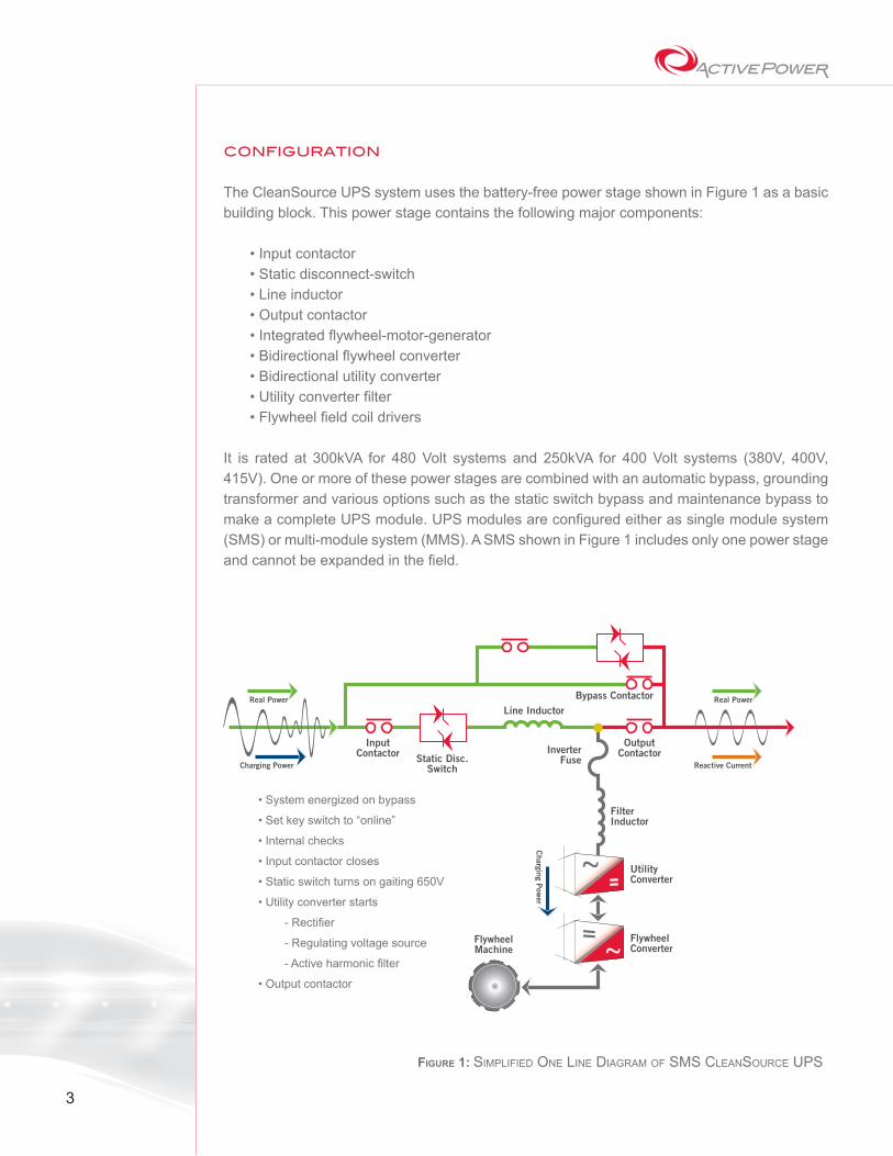
CONFIGURATION
The CleanSource UPS system uses the battery-free power stage shown in Figure 1 as a basic building block. This power stage contains the following major components:
• Input contactor• Static disconnect-switch• Line inductor• Output contactor• Integrated flywheel-motor-generator• Bidirectional flywheel converter• Bidirectional utility converter• Utility converter filter• Flywheel field coil drivers
It is rated at 300kVA for 480 Volt systems and 250kVA for 400 Volt systems (380V, 400V, 415V). One or more of these power stages are combined with an automatic bypass, grounding transformer and various options such as the static switch bypass and maintenance bypass to make a complete UPS module. UPS modules are configured either as single module system (SMS) or multi-module system (MMS). A SMS shown in Figure 1 includes only one power stage and cannot be expanded in the field.
InputContactor
Real Power
OutputContactorInverter
Fuse
FilterInductor
UtilityConverter
FlywheelConverter
FlywheelMachine
Bypass ContactorLine Inductor
Static Disc.Switch
Real Power
Charging Power Reactive Current
Charging P
ower
Figure 1: Simplified One line diagram Of SmS CleanSOurCe upS
• System energized on bypass
• Set key switch to “online”
• Internal checks
• Input contactor closes
• Static switch turns on gaiting 650V
• Utility converter starts
- Rectifier
- Regulating voltage source
- Active harmonic filter
• Output contactor
4
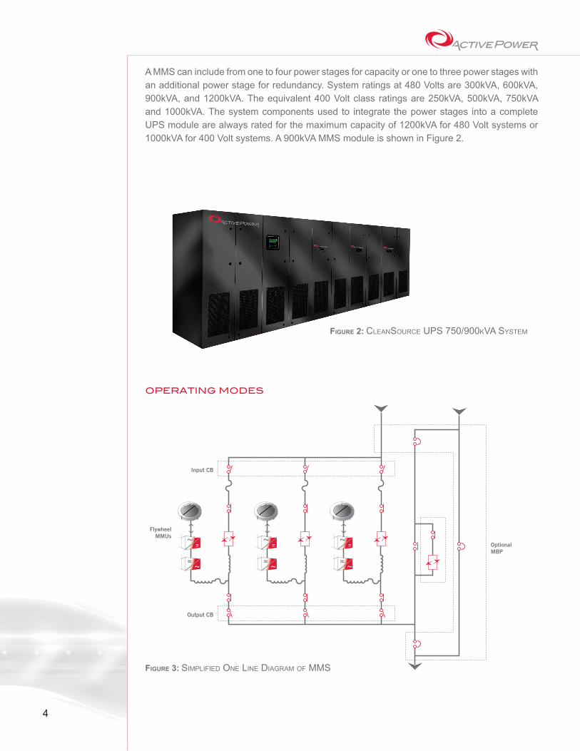
A MMS can include from one to four power stages for capacity or one to three power stages with an additional power stage for redundancy. System ratings at 480 Volts are 300kVA, 600kVA, 900kVA, and 1200kVA. The equivalent 400 Volt class ratings are 250kVA, 500kVA, 750kVA and 1000kVA. The system components used to integrate the power stages into a complete UPS module are always rated for the maximum capacity of 1200kVA for 480 Volt systems or 1000kVA for 400 Volt systems. A 900kVA MMS module is shown in Figure 2.
OPERATING MODES
Figure 2: CleanSOurCe upS 750/900kVa SyStem
FlywheelMMUs
Input CB
OptionalMBP
Output CB
Figure 3: Simplified One line diagram Of mmS

5
A SMS UPS as shown in Figure 1 will be used to explain the various system operating modes. In MMS (shown in Figure 3), all power stages are paralleled and operate identically except for the redundant power stage in systems programmed for N+1 operation. N+1 operation will also be reviewed.
Start-UpThe UPS output is energized on bypass as soon as power is applied to the system. The UPS is then started using a completely automated process. Placing a key switch in the online position begins start-up. The UPS performs internal checks to ensure all control and monitoring functions are operating properly and the input contactor closes.
The static disconnect switch turns on and the conduction angle is rapidly increased from zero to an angle that causes the direct current (DC) bus voltage between utility converter and the flywheel converter to reach approximately 650 Volts through the rectifying action of the freewheeling diodes in the utility converter. As soon as this DC value is reached, the static switch turns on fully.
The utility converter insulated gate bipolar transistor (IGBT) begins to operate which allows the converter to act as a rectifier, a regulating voltage source and an active harmonic filter. The DC bus is then increased to normal operating voltage of approximately 800 Volts and the output bus is transferred from bypass to the output of the power stage. The transfer is accomplished by closing the output contactor and opening the bypass in a make-before-break manner.
The firing of the silicon controlled rectifier (SCR) in the static disconnect switch is now changed so that each SCR in each phase is only turned on during the half cycle, which permits real power to flow from the utility supply to the UPS. This firing pattern prevents power from the flywheel from feeding backwards into the supply and assures all of the flywheel energy is available to support the load.
Immediately after the output is transferred from bypass to the power stage, the flywheel field is excited which also provides magnetic lift to unload the flywheel bearings. The flywheel inverter is then turned on and gradually increases frequency at a constant rate to accelerate the flywheel to approximately 60 rotations per minute (rpm). Once the flywheel reaches 60 rpm, the flywheel inverter controls the acceleration to keep currents below the maximum charging and the maximum input settings. Once the flywheel reaches 4,000 rpm, the UPS is fully functional and capable of supporting the load during a power outage. Acceleration continues until the flywheel reaches full charge at 7,700 rpm. Total time to complete the start-up sequence is less than five minutes.
Normal OperationOnce the system is started and the flywheel is operating at greater than 4,000 rpm, the UPS is in normal operation. In this operating mode, the UPS regulates output voltage and supplies reactive and harmonic currents required by the load. At the same time, it cancels the effect of load current harmonics on the UPS output voltage. Analyzing the components of the input and output currents as shown in Figure 1 makes it easier to understand normal operation of the UPS.

6
One component of the input current is real current that supplies power to the load. Real current is current that is in phase with the supply voltage and supplies real power (kW) to the load. When flowing through the line inductor, this component of the input current causes a phase shift across the line inductor rather than boosting or bucking voltage. The line inductor impedance is chosen to limit the phase shift to less than 10 degrees at full load. Keeping the phase shift this small ensures the UPS can instantaneously transfer to bypass without causing unacceptable voltage or phase transients to the load.
The second component of the input current is reactive current that circulates between the input and the utility converter to regulate the output voltage. Leading reactive current (90 degrees ahead of the voltage) through the line inductor causes a voltage boost across the line inductor from input to output. Lagging reactive current (90 degrees behind the voltage) causes a bucking voltage. By controlling the utility converter to maintain nominal output voltage, just enough leading or lagging reactive current flows through the line inductor to make up the difference between the input voltage at any point in time and nominal output voltage. The input voltage is sampled every 50 microseconds to allow the utility converter to reach very quickly to input voltage transients and steady state voltage fluctuations.
The final component of the input current is real current that is used to keep the flywheel fully charged or to recharge the flywheel after a discharge. The power required to maintain full charge is less than 2kW so this current is small in normal operation. The utility converter rectifies the AC voltage and supplies DC power to the flywheel converter. The IGBTs of the flywheel converter are gated to provide small pulses of motoring current to keep the flywheel charged.
The load current has two components in addition to the real current that is supplied from the input source. These components are reactive current and harmonics current. The utility inverter supplies both of these additional components. Since these components of the total load current contribute no net power to the load, no flywheel energy is used to supply these currents. They circulate between the utility converter and the load. The power stage controls analyze the harmonic current requirements of the load and set the firing of the IGBTs to make the utility inverter a very low impedance source to any harmonic currents that are present. Therefore, highly non-linear load currents are supplied almost entirely from the utility converter with little effect on the quality of the UPS output voltage waveform and with almost no transmission of load harmonic currents to the input of the UPS. If the harmonic currents of the load current changes, utility converter gating is changed to provide dynamic harmonic cancellation for the changing load.
Because the utility converter supplies the harmonic and reactive components of the load current, load power factor has little effect on input power factor. The amount of reactive current on the input is determined almost entirely by the difference between the actual root mean square (RMS) input voltage and the nominal RMS voltage. At nominal voltage, the input power factor is unity regardless of the load power factor. For a given input voltage deviation above or below nominal, a specific amount of lagging current or leading current, respectively, must flow between the input and the utility converter to correct the voltage deviation. Because input power factor is the ratio of real current to total current, the input power factor depends on both the amount of reactive current and the amount of real current. Therefore, the input power factor is a function of both the deviation of the input voltage from nominal and the load power (kW). At light loads, the total current will be less while the reactive current remains the same for a given input voltage deviation. Thus, the input power factor spans a wider range at partial load,

7
but it remains leading for low voltages and lagging for high voltages. These are much more desirable input power factor characteristics than the normal characteristics of traditional double conversion UPS because it does not interfere with the voltage regulation of generator sets. It actually helps generator sets regulate voltage. Leading current helps the generator boost its voltage when the voltage is low and lagging current helps the generator reduce its voltage when the voltage is high. In comparison, the typical double conversion UPS has a very leading input power factor at light load regardless of whether the input voltage is low or high. During UPS walk-in after a transfer to standby power, this leading current can cause generator output voltage to climb above acceptable levels and shut down the engine generators.
Discharge ModeThe UPS senses the deviation of voltage or frequency beyond programmed tolerances and quickly disconnects the UPS from the supply by turning off the static disconnect switch and opening the input contactor. In most instances, the UPS disconnects instantaneously, but in all cases, it will disconnect in less than one-half cycle. At the same time the utility converter starts delivering power from the DC bus to the load and the flywheel converter changes the firing point of its IGBTs to delivery power to the utility converter through the DC bus. The UPS maintains a clean output voltage to the load. The output voltage transient for loss and return of input voltage at full load is less than 3 percent.
The UPS uses several techniques to quickly detect a utility failure. The first method is RMS voltage detection. Every fifth cycle, the RMS value of the input voltage is calculated from the 334 samples taken over one complete cycle of the input voltage. If the RMS value of the input voltage deviates from nominal by more than the limit programmed into the UPS, the UPS will disconnect from the input and enter discharge mode. RMS voltage detection is effective for relatively slow changes in input voltage.
The UPS also detects input voltage transients by sampling the input voltage every 50 microseconds and comparing to the corresponding point of a stored sine wave that has a RAM value equal to the previous RMS input voltage measurement. If the sample deviates from the stored sine wave by more than the amount programmed into the UPS, the UPS disconnects from the input source and enters discharge mode. Transient detection occurs very quickly. The total delay between sampling the input voltage and discharging the flywheel is about 500 microseconds.
The third method of detecting a utility failure is variation in DC bus voltage. In some cases, the input voltage appears to remain nominal, but current cannot be supplied to the UPS by the input source. In these cases, the DC bus voltage will immediately begin to decay. A reduction in DC voltage greater than a preprogrammed threshold triggers a transfer to discharge mode. The final method of detecting input failure is to compare input frequency to nominal frequency.
A frequency measurement and comparison is made every cycle by comparing the period between positive slope zero crossings to the period at nominal frequency. This combination of methods ensures the UPS will always detect an input power failure and discharge the flywheel before the output voltage is affected.

8
Recharge ModeWhen input power is restored to acceptable limits, the UPS synchronizes the output and input voltages, closes the input contactor and turns on the static disconnect switch. The utility converter then walks power from the flywheel to the input source by linearly increasing the real input current. The ramping time is programmable from one second to 15 seconds. As soon as the load power is completely walked-in, the utility converter and flywheel converter start to recharge the flywheel and return to normal operation. The recharge power is programmable between 25kW and 70kW per flywheel. Maximum recharge power results in an increase to the UPS input current of 85 Amps. Recharging is accomplished by controlling the utility and flywheel converters in a similar way as is used to maintain full charge in normal operation, but the IGBT gating points are changed to increase current into the flywheel. Recharge current is ramped on and off to avoid any step loads on the power supply to optimize operation from standby generators.
PARALLELING POWER STAGES
MMS modules use multiple power stages operating in parallel as shown in Figure 3. Each power stage contains a complete set of paralleling controls and communications between power stages are routed via redundant serial busses. In normal operation, real power is shared among stages simply by building all of the line inductors the same. Reactive current is shared by monitoring the AC current of the utility converter in each power stage and matching each current to the average of all stages. Maximum unbalance among power stages is limited to less than 5 percent.
In discharge mode, the phase angles and amplitudes of all utility converters are matched to the average, which balances real and reactive current among power stages and ensures the output frequency remains constant.
N+1 REDUNDANCY
All MMS modules can be equipped with a redundant power stage. There is no difference in hardware between an N+1 MMS and the next larger non-redundant system. For example, a 300kVA N+1 UPS and a 600kVA full power UPS have identical hardware. In an N+1 configuration, one of the power stages operates differently from the others. If all of the power stages of an N+1 system operated identically, the UPS would behave like a higher capacity UPS module operating at reduced load. Reactive current would have to be supplied through all N+1 line inductors to regulate load voltage. The extra current flowing through the additional line inductor affects efficiency, input current and input power factor. To avoid these effects, the redundant power stage is operated with its static disconnect switch open. This means no current flow through the line inductor of the redundant power stage and no additional current is needed for voltage regulation through this line inductor. The redundant flywheel is charged like the others using power from the output power bus rather than through its own static disconnect switch and line inductor.
The redundant flywheel is also discharged in unison with the others, sharing power equally and proportionally extending the ride-through time of the UPS. The redundant utility converter shares reactive current with the other stages and supplies voltage regulating current through the

9
line inductors in other stages and reactive and harmonic current to the load. This proportionally reduces the amount of current that must be supplied from the other power stages. In effect, everything in the redundant power stage operates like the other power stages except the static disconnect switch remains open.
If any power stage fails, the redundant power stage takes over in less than 500 microseconds by turning on its static disconnect switch. In order to ensure the redundant unit is always capable of operation as a primary power stage, the redundant role is rotated between power stages on a pre-programmed periodic basis. Transfer of redundant status from one power stage to another is accomplished in a fail-safe manner by closing the static switch of the redundant unit and monitoring proper primary operation before making another power stage assume the redundant role.
CONCLUSION
The CleanSource battery-free UPS supplies superior, fast- responding UPS performance using high efficiency line-interactive UPS technology. The UPS:
• Maintains excellent output power quality for highly non-linear and conventional loads and at the same time assures low input current harmonics
• Eliminates the need for input filters• Presents an input power factor that helps regulate upstream utility voltage• Integrates easily with engine generators and recharges quickly
CleanSource UPS includes modular construction to allow convenient installation and service, capacity expansion in the field and cost effective internal UPS redundancy.
© ® TM 2007 Active Power, Inc. All rights reserved.WP-108