Embed Size (px)
Citation preview

OPERATION AND MAINTENANCE HANDBOOK
®
D407270XA
vers. 1.0

Thank you for choosing one of Silca’s high quality key cuttingmachines. This machine has been designed, tested and producedin our factory using the most modern technology to provide you withmany excellent years of precision key duplicating.Before using the machine, we suggest that you read the informationpresented in this manual throughly.The proper care and maintenance that your machine requires is alsodetailed in this handbook.By following these instructions you will ensure a long, trouble freelife for your machine.If anything is at all unclear, please contact your supplier, who directlyor by means of Silca’s Technical Service Department will provideyou with the service and assistance you require.

INDEX
BRAVO FEATURES ........................................................................................... 1
TECHNICAL DATA ............................................................................................. 1
ACCESSORIES .................................................................................................. 1
PARTS OF THE BRAVO .................................................................................... 2
CHECKING CALIBRATION OF THE MACHINE ............................................... 3
TO CUT WORN KEYS ........................................................................................ 3
SPACE SETTING ............................................................................................... 4
THE JAWS .......................................................................................................... 5
USE OF THE PINS ............................................................................................. 6
CUTTING CRUCIFORM KEYS WITH ONE SHOULDER ................................. 6
CUTTING BEST KEYS ....................................................................................... 6
REPLACING THE CUTTER ............................................................................... 7
REPLACING THE BRUSH ................................................................................. 7
BELT TENSION AND REPLACEMENT ............................................................. 8
REPLACING THE TRACER POINT ................................................................... 8
TO SET THE STOP POSITION OF THE CARRIAGE ....................................... 9
MAINTENANCE .................................................................................................. 9
WARRANTY ........................................................................................................ 9
ELECTRICAL DIAGRAM .................................................................................. 10


Operating Manual BRAVO II
BRAVO FEATURES
• Professional key cutting machine for automobile, household cylinder keys and cruciform keys.• Micrometer adjustment for the tracer.• Removable chip tray.• Tynex brush.• Carriage operates on twin rods with sealed bushings.• Carriage is automatically released once the gauges are disengaged.• Carriage locks in down position.• Machined jaws give excellent grip with minimal pressure.
TECHNICAL DATA
MOTOR: single phase 110V-60Hz
CUTTER: High speed steel dia. 3.15” x 0.197” x 0.63” (80 mm x 5 mm x 16 mm)
MOVEMENT: on bearings. Self cleaning synthetic bushings.
JAWS: four side, revolving.
SAFETY DEVICE: carriage is released only when the gauges are out of safety position.
MAX. CUT. LGTH.: 2.09”
DIMENSIONS: length 18.11”, width 14.96”, height 9.65”
WEIGHT: 39.7 lbs.
ACCESSORIES
Pair of ø 0.047” steel pinsCode D401224ZZ (each)
Pair of setting blanksfor calibratingCode D401561BA (each)
Pair of steel tip stopswith neckCode D402301BA (each)
Pair of ø 0.066”steel pinsCode D401225ZZ (each)
Locking bar forcutter removalCode D400754BA
Set of allen keys (6 pcs.)2mm, 2.5mm3mm, 4mm, 5mm, 6mm
Wrench 19mmCode D300783ZZ
Pair of steel tip stopsCode D402302BA (each)
1

Operating Manual BRAVO II
PARTS OF THE BRAVO
A) Original keyB) Key blankC) CutterD) Tracer pointD1) Tracer point supportF) Complete carriage assemblyG) JawH) Jaw handleJ) Transparent cutter shieldL) BrushM) Tracer point locking screwM1) Tracer point lock nutN) Key gaugeO) Carriage leverP) Brush switcQ) Chip trayR) Tracer point adjusting screwR1) MicrometerS) On/Off switchT) Carriage release buttonU) Key gauge drumW) Belt coverY) MotorZ) Carriage handle
Fig. 1
MM1
J
W
C
L
B
H
G
T
F
Q
ZUGN
A
O
S
P
D
D1
R1
R
Y
2
Operating Manual BRAVO II
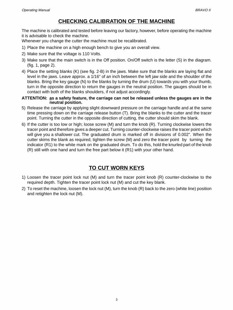
CHECKING CALIBRA TION OF THE MACHINE
The machine is calibrated and tested before leaving our factory, however, before operating the machineit is advisable to check the machine.Whenever you change the cutter the machine must be recalibrated.
1) Place the machine on a high enough bench to give you an overall view.
2) Make sure that the voltage is 110 Volts.
3) Make sure that the main switch is in the Off position. On/Off switch is the letter (S) in the diagram.(fig. 1, page 2).
4) Place the setting blanks (K) (see fig. 2-B) in the jaws. Make sure that the blanks are laying flat andlevel in the jaws. Leave approx. a 1/16” of an inch between the left jaw side and the shoulder of theblanks. Bring the key gauge (N) to the blanks by turning the drum (U) towards you with your thumb,turn in the opposite direction to return the gauges in the neutral position. The gauges should be incontact with both of the blanks shoulders, if not adjust accordingly.
ATTENTION: as a safety feature, the carriage can not be released unless the gauges are in theneutral position.
5) Release the carriage by applying slight downward pressure on the carriage handle and at the sametime pressing down on the carriage release button (T). Bring the blanks to the cutter and the tracerpoint. Turning the cutter in the opposite direction of cutting, the cutter should skim the blank.
6) If the cutter is too low or high; loose screw (M) and turn the knob (R). Turning clockwise lowers thetracer point and therefore gives a deeper cut. Turning counter-clockwise raises the tracer point whichwill give you a shallower cut. The graduated drum is marked off in divisions of 0.002”. When thecutter skims the blank as required, tighten the screw (M) and zero the tracer point by turning theindicator (R1) to the white mark on the graduated drum. To do this, hold the knurled part of the knob(R) still with one hand and turn the free part below it (R1) with your other hand.
TO CUT WORN KEYS
1) Loosen the tracer point lock nut (M) and turn the tracer point knob (R) counter-clockwise to therequired depth. Tighten the tracer point lock nut (M) and cut the key blank.
2) To reset the machine, loosen the lock nut (M), turn the knob (R) back to the zero (white line) positionand retighten the lock nut (M).
3

Operating Manual BRAVO II
SPACE SETTING
1) Place the set up blanks in the jaws as shown in fig. 2-A using the key gauge (N) with the groovesfacing the cutter.
2) Make sure to leave the main switch off. Release the carriage and position the blanks so that thegrooves come in contact with the cutter and tracer point. Turn the cutter a complete revolution byhand in the opposite direction of cutting. The cutter should skim both sides of the groove, in otherwords the cutter should fit squarely in the groove.
3) If the cutter skims only one side of the blank, loosen screw (M1) and move the tracer point support(D1) sideways. When the cutter skims both sides of the blank, tighten the screw (M1).
4) Use the carriage handle (Z) to return the carriage to the neutral position. The carriage willautomatically lock in position. The machine is now ready for operation.
IMPORTANT: when the set up blanks have been used a number of times, they must be replaced.Two identical blanks can be used as an alternative.
Fig. 2
KM
U
T
Z
K
NDD1R1
R
M1
A
B
4

Operating Manual BRAVO II
THE JAWS
The jaws rotate to allow perfect clamping of all cylinder keys against the back and the profile.Side A & B of the jaws are used for keys that are cut on one side such as normal household cylindertype keys. Jaw side A (shown in fig. 3) is used for keys with shallow cuts (min. 0.148” original key bladewidth).Jaw side B is used for keys with a deeper cut (min.original key blank width of 0.108”). Both of these jawpositions are shown in fig. 4 below. Make sure that the keys are laying flat inside the jaw and theshoulder is resting against the jaw face or against the key gauge (N).Side C & D of the jaws are used for foreign car keys and keys that are cut on both sides. For doublesided keys that need to be clamped by the groove on the underside of the key, turn the jaws to side Cas shown in fig. 5.Insert the key with the groove facing downwards, using the lip on the lower part of the jaw as a guide.For keys with a flat surface, be sure they are inserted parallel to the base of the jaw.For keys that are double sided that needs to be clamped by the groove on top of the key, the jaws mustbe rotated to side D as shown in fig. 6.Insert the keys with the groove upwards using the lip on the upper portion of the jaw as a guide.Again make sure that the keys with smaller flat surfaces are inserted parallel to the jaw base.
IMPORTANT: the jaw handles have bearing discs and therefore require minimum pressure totighten them. The key is fully secured by “SNUGGING” the handles. It is recommended that youkeep from overtightening to avoid damaging the jaws over a period of time.
Fig. 3
Fig. 4
Fig. 5Fig. 6
0.108”
0.148”
5

Operating Manual BRAVO II
USE OF THE PINS
For broken keys use one of the steel pins #D401224ZZ or #D401225ZZ and insert into the groove ofthe key so that the key is properly aligned for cutting as shown in fig. 7.
Fig. 7
CUTTING CRUCIFORM KEYS WITH ONE SHOULDER
Using side A of the jaw, most of types of the cruciform key can be cut except for the Y & T profiles. Thekey must be re-positioned in the jaw to cut each of the three sides of the key. The steel tip stops(#D402301BA) are used to do this. Refer to fig. 8 as you are reading this section.
1) Do not use the key gauges.
2) Place the bars into one of the slots in the jaws, insert the original and the key blank in their properjaw until they stop against the bar using the shoulder on the blade of the key. Tighten the jaws byturning the handles.
3) Cut the first side then rotate the keys on both sides to the next side you wish to duplicate. Slide theshoulder of the keys against the stop bar to properly gauge the key for the next cut. Tighten the jawsagain by turning the handles.
4) Repeat step three for the third side to complete duplication.
Fig. 8
CUTTING BEST KEYS
Use side A of the jaw to cut the Best keys. You should use the tip stops #D402301BA to cut these keys.
1) Insert the tip stops in the last slot on the jaws, insert the original key and the key blank into theirproper jaws until they stop. Tighten the jaws by turning the handles.
2) Cut the key blank, and repeat previous instruction to cut generations.
1 2 3
6

Operating Manual BRAVO II
REPLACING THE CUTTER
1) Raise the cutter shield (J) and insert the locking bar (#D400754BA) into the slot in the base and thehole in the cutter shaft next to the cutter as shown in fig. 9.
2) Use the wrench (#D300783ZZ) that was provided to loosen the nut.
IMPORTANT: the thread is a left handed.3) When replacing the cutter, make sure that the longest sharpened angle of the cutter is facing to the
right.
4) Clean the cutter and the shaft before installing the cutter.
5) Tighten the lock nut. Make sure to remove the locking bar from the slot before starting themachine .
Fig. 9
REPLACING THE BRUSH
1) Unscrew the four screws holding the belt shield and remove the shield.
2) Raise the cutter shield (J) and insert the locking bar (#D400754BA) into the groove in the base andthe hole in the cutter shaft as shown in fig. 10.
3) Remove the allen screw with one of the allen keys that was provided.
4) Replace the brush.
5) After you replace everything, make sure that you remove the locking bar from the slot.
Fig. 10
D400754BA
D300783ZZ
J
D400754BA
D301820ZZ
J
7

Operating Manual BRAVO II
BELT TENSION AND REPLACEMENT
If the belt should come loose, remove the shield, and loosen the four nuts (*) holding the motor to thebase (fig. 11). Adjust the position of the motor until the belt tension is tight (about 1/2” play in thebelt).The belt is replaced the same way.
Fig. 11
REPLACING THE TRACER POINT
1) Completely unscrew the tracer point knob (R) and remove it as shown in fig. 12.
2) Completely unscrew (R2), loosen the dowl (M) and remove the tracer point (D) as shown in fig. 13.
3) Replace the tracer point, carrying out the instructions described in #2 in reverse order.
4) Replace the knob (R) and tighten. Re-set the machine following the instructions on page 3.
Fig. 12
Fig. 13
*
R M
D
R2 D
M
8
Operating Manual BRAVO II
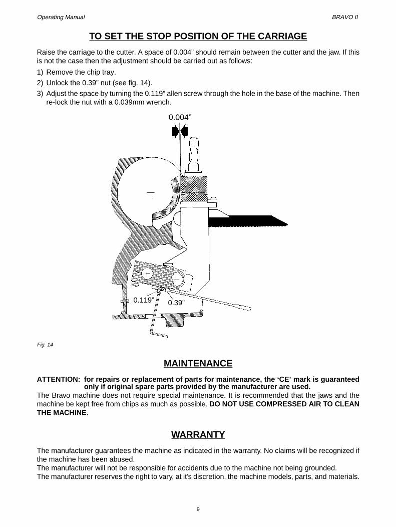
TO SET THE STOP POSITION OF THE CARRIAGE
Raise the carriage to the cutter. A space of 0.004” should remain between the cutter and the jaw. If thisis not the case then the adjustment should be carried out as follows:
1) Remove the chip tray.
2) Unlock the 0.39” nut (see fig. 14).
3) Adjust the space by turning the 0.119” allen screw through the hole in the base of the machine. Thenre-lock the nut with a 0.039mm wrench.
Fig. 14
MAINTENANCE
ATTENTION: for repairs or replacement of parts for maintenance, the ‘CE’ mark is guaranteedonly if original spare parts provided by the manufacturer are used.
The Bravo machine does not require special maintenance. It is recommended that the jaws and themachine be kept free from chips as much as possible. DO NOT USE COMPRESSED AIR TO CLEANTHE MACHINE.
WARRANTY
The manufacturer guarantees the machine as indicated in the warranty. No claims will be recognized ifthe machine has been abused.The manufacturer will not be responsible for accidents due to the machine not being grounded.The manufacturer reserves the right to vary, at it’s discretion, the machine models, parts, and materials.
0.004”
0.119” 0.39”
9

Operating Manual BRAVO II
ELECTRICAL DIA GRAM
Fig. 15
1) Main switch
2) Brush button
3) Microswitch
4) Motor
5) Fuses (6,3)
blue
brown
red
black
grey
purple
blue
brow
n
blac
k
grey
grey
10

SILCA S.p.A.Via Podgora, 20 (Z.I.) 31029 VITTORIO VENETO (TV)
Tel. 0438 9136 Fax 0438 913800www.silca.it
Member of the Kaba Group