Embed Size (px)
Citation preview

OM-2076D080604 – Original
Operation and Maintenance Manual with
Illustrated Parts Listfor
90DZ20
90 kVA, 3 Phase, 115/200 Volt,400 Hz. Generator Set
Series 500047D
ITW GSE GroupHobart Ground Power
Troy, Ohio 45373U.S.A.


WarrantyHOBART GROUND POWER
TROY, OHIO 45373
Data Sheet 165Index: 990223Replaces: 980601
1. Hobart Brothers Company (hereinafter called HOBART) warrants that each new and unused Hobart Ground PowerEquipment, (hereinafter called the PRODUCT) is of good workmanship and is free from mechanical defects,provided that (1) the PRODUCT is installed and operated in accordance with the printed instructions of HOBART,(2) the PRODUCT is used under the normal operating conditions for which it is designed, (3) the PRODUCT is notsubjected to misuse, negligence or accident, and (4) the PRODUCT receives proper care, lubrication, protection,and maintenance under the supervision of trained personnel.
2. This warranty expires 15 months after shipment by HOBART to the first user, or 12 months after installation,whichever first occurs.
3. This warranty does not apply to: primary and secondary switch contacts, cable connectors, carbon brushes, fuses,bulbs, and filters unless found to be defective prior to use.
4. Hobart DOES NOT WARRANT THE FOLLOWING COMPONENTS: Engines, engine components ; such as:starters, alternators, regulators, governors, etc., and cable retrieving devices. Many of the foregoing componentsare warranted directly by the manufacturer to the first user and serviced by a worldwide network of distributors andothers authorized to handle claims for component manufacturers. A first user’s claim should be presented directlyto such an authorized component service outlet. In the event any component manufacturer has warranted itscomponent to HOBART and will not deal directly with a first user then HOBART will cooperate with the first userin the presentation of a claim to such manufacturer. Under NO circumstances does HOBART assume any liabilityfor any warranty claim against or warranty work done by or in behalf of any manufacturer of the foregoingcomponents.
5. This warranty is extended by HOBART only to the purchaser of new PRODUCTS from HOBART or one of itsauthorized distributors. The PRODUCTS purchased under this warranty are intended for use exclusively by thebuyer and his employees and by no other persons and, therefore, there shall be no third party beneficiary to thiswarranty.
6. A claim of defects in any PRODUCT covered by this warranty is subject to HOBART factory inspection andjudgment. HOBART’S liability is limited to repair of any defects found by HOBART to exist, or at HOBART’Soption the replacement of the defective product, F.O.B. factory, after the defective product has been returned by thepurchaser at its expense to HOBART’S shipping place. Replacement and exchange parts will be warranted for theremainder of the original Warranty, or for a period of ninety (90) days, whichever is greater.
7. UNDER NO CIRCUMSTANCES whatsoever shall HOBART and its authorized distributors be liable for anyspecial or consequential damages, whether based on lost goodwill, lost resale profits, work stoppage impairmentof other goods or otherwise, and whether arising out of breach of any express or implied warranty, breach ofcontract, negligence or otherwise, except only in the case of personal injury as may be required by applicable law.
8. Continued use of the PRODUCT(S) after discovery of a defect VOIDS ALL WARRANTIES.9. Except as authorized in writing, this warranty does not cover any equipment that has been altered by any party
other than HOBART.10. THERE ARE NO WARRANTIES WHICH EXTEND BEYOND THE DESCRIPTION ON THE FACE HERE
OF. HOBART MAKES NO WARRANTIES, EXPRESSED OR IMPLIED, OF MERCHANTABILITY ORFITNESS FOR A PARTICULAR PURPOSE.
11. HOBART neither assumes nor authorizes any person to assume for HOBART any liability in connection with thePRODUCTS sold, and there are no oral agreements or warranties collateral to or affecting this written Warranty.This warranty and all undertakings of HOBART thereunder shall be governed by the laws of the State of Ohio,United States of America.
WARNINGAT ALL TIMES, SAFETY MUST BE CONSIDERED AN IMPORTANT FACTOR IN THE INSTALLATION,
SERVICING AND OPERATION OF THE PRODUCT, AND SKILLED, TECHNICALLY QUALIFIEDPERSONNEL SHOULD ALWAYS BE EMPLOYED FOR SUCH TASKS.


OM-2076D / Operation and Maintenance Manual90DZ20/ Series 500047D/ 400 Hz. Generator Set
August 6, 2004 Safety WarningsPage 1
Safety Warnings and Cautions
WARNINGELECTRIC SHOCK can KILL. Do not touch live electrical parts.
ELECTRIC ARC FLASH can injure eyes, burn skin, cause equipment damage, andignite combustible material. DO NOT use power cables to break load and prevent toolsfrom causing short circuits.
IMPROPER PHASE CONNECTION, PARALLELING, OR USE can damage this andattached equipment.
IMPORTANTProtect all operating personnel. Read, understand, and follow all instructions in theOperating/Instruction Manual before installing, operating, or servicing the equipment.Keep the manual available for future use by all operators.
WARNINGCALIFORNIA PROPOSITION 65 - DIESEL ENGINES. Diesel engine exhaust andsome of its constituents are known to the State of California to cause cancer, birthdefects and other reproductive harm.
1) General
Equipment that supplies electrical power can cause serious injury or death, or damage to other equipment orproperty. The operator must strictly observe all safety rules and take precautionary actions. Safe practiceshave been developed from past experience in the use of power source equipment. While certain practicesbelow apply only to electrically-powered equipment, other practices apply to engine-driven equipment, andsome practices to both.
2) Shock Prevention
Bare conductors, terminals in the output circuit, or ungrounded, electrically live equipment can fatally shock aperson. Have a certified electrician verify that the equipment is adequately grounded and learn whatterminals and parts are electrically HOT. Avoid hot spots on machine. Use proper safety clothing,procedures, and test equipment.
The electrical resistance of the body is decreased when wet, permitting dangerous currents to flow through it.When inspecting or servicing equipment, do not work in damp areas. Stand on a dry rubber mat or dry wood,and use insulating gloves when dampness or sweat cannot be avoided. Keep clothing dry, and never workalone.
a) Installation and Grounding of Electrically Powered Equipment
Equipment driven by electric motors (rather than by diesel or gasoline engines) must be installed andmaintained in accordance with the National Electrical Code, ANSI/NFPA 70, or other applicablecodes. A power disconnect switch or circuit breaker must be located at the equipment. Check thenameplate for voltage, frequency, and phase requirements. If only 3-phase power is available,connect any single-phase rated equipment to only two wires of the 3-phase line. DO NOT CONNECTthe equipment grounding conductor (lead) to the third live wire of the 3-phase line, as this makes theequipment frame electrically HOT, which can cause a fatal shock.

OM-2076D / Operation and Maintenance Manual90DZ20/ Series 500047D/ 400 Hz. Generator Set
August 6, 2004 Safety WarningsPage 2
Always connect the grounding lead, if supplied in a power line cable, to the grounded switch box orbuilding ground. If not provided, use a separate grounding lead. Ensure that the current (amperage)capacity of the grounding lead will be adequate for the worst fault current situation. Refer to theNational Electrical Code ANSI/NFPA 70 for details. Do not remove plug ground prongs. Use correctlymating receptacles.
b) Output Cables and Terminals
Inspect cables frequently for damage to the insulation and the connectors. Replace or repair crackedor worn cables immediately. Do not overload cables. Do not touch output terminal while equipment isenergized.
3) Service and Maintenance
This equipment must be maintained in good electrical condition to avoid hazards stemming fromdisrepair. Report any equipment defect or safety hazard to the supervisor and discontinue use of theequipment until its safety has been assured. Repairs should be made by qualified personnel only. Beforeinspecting or servicing this equipment, take the following precautions:
a) Shut off all power at the disconnecting switch, or line breaker, or by disconnecting battery, beforeinspecting or servicing the equipment.
b) Lock switch OPEN (or remove line fuses) so that power cannot be turned on accidentally.
c) Disconnect power to equipment if it is out of service.
d) If troubleshooting must be done with the unit energized, have another person present who is trainedin turning off the equipment and providing or calling for first aid.
4) Fire And Explosion Prevention
Fire and explosion are caused by electrical short circuits, combustible material near engine exhaustpipes, misuse of batteries and fuel, or unsafe operating or fueling conditions.
a) Electrical Short Circuits and Overloads
Overloaded or shorted equipment can become hot enough to cause fires by self-destruction or bycausing nearby combustibles to ignite. For electrically powered equipment, provide primary inputprotection to remove short circuited or heavily overloaded equipment from the line.
b) Batteries
Batteries may explode and/or give off flammable hydrogen gas. Acid and arcing from a rupturedbattery can cause fires and additional failures. When servicing, do not smoke, cause sparking, or useopen flame near the battery.
c) Engine Fuel
Use only approved fuel container or fueling system. Fires and explosions can occur if the fuel tank isnot grounded prior to or during fuel transfer. Shut unit DOWN before opening fuel tank cap. DO NOTcompletely fill tank, because heat from the equipment may cause fuel expansion overflow. Remove
OM-2076D / Operation and Maintenance Manual90DZ20/ Series 500047D/ 400 Hz. Generator Set
August 6, 2004 Safety WarningsPage 3
all spilled fuel IMMEDIATELY, including any that penetrates the unit. After clean-up, open equipmentdoors and blow fumes away with compressed air.
5) Toxic Fume Prevention
Carbon monoxide - Engine exhaust fumes can kill and cause health problems. Pipe or vent the exhaustfumes to a suitable exhaust duct or outdoors. Never locate engine exhausts near intake ducts of airconditioners.
6) Bodily Injury Prevention
Serious injury can result from contact with fans or hot spots inside some equipment. Shut DOWN suchequipment for inspection and routine maintenance. When equipment is in operation, use extreme care indoing necessary trouble-shooting and adjustment. Do not remove guards while equipment is operating.
7) Medical and First Aid Treatment
First aid facilities and a qualified first aid person should be available for each shift for immediate treatmentof all injury victims. Electric shock victims should be checked by a physician and taken to a hospitalimmediately if any abnormal signs are observed.
EMERGENCYFIRST AID Call physician immediately. Seek additional assistance. Use First Aid techniques
recommended by American Red Cross until medical help arrives.
IF BREATHING IS DIFFICULT, give oxygen, if available, and have victim lie down.FOR ELECTRICAL SHOCK, turn off power. Remove victim; if not breathing, beginartificial respiration, preferably mouth-to-mouth. If no detectable pulse, begin externalheart massage. CALL EMERGENCY RESCUE SQUAD IMMEDIATELY.
8) Equipment Precautionary Labels
Inspect all precautionary labels on the equipment monthly. Order and replace all labels that cannot beeasily read.

OM-2076D / Operation and Maintenance Manual90DZ20/ Series 500047D/ 400 Hz. Generator Set
August 6, 2004 Safety WarningsPage 4
This page intentionally left blank.

OM-2076D / Operation and Maintenance Manual90DZ20/ Series 500047D/ 400 Hz. Generator Set
August 6, 2004 IntroductionPage 1
Introduction
This manual contains operation and maintenance information for a 90DZ20, 400 Hz Generator Setmanufactured by ITW GSE Group, Hobart Ground Power, Troy, Ohio 45373.
This manual is not intended to be a textbook on electricity or electronics. Its primary purpose is to provideinformation and instructions to experienced operators, electricians, and mechanics who have never operatedthis equipment. It is the intent of this manual to guide and assist operators and maintenance people in theproper use and care of the equipment.
Use of the manual should not be put off until a trouble or need for help develops. Read the instructionsbefore starting the unit. Learn to use the manual and to locate information contained in it. Its style andarrangement are very similar to commercial aircraft manuals.
The manual is divided into five chapters plus an appendix. Each chapter is divided into as many sections asrequired. Each new section starts with page 1. Each page is identified by chapter, section and page number,which are located in the lower, outside corner. When information located in another portion of the manual isreferred to, its location is identified by a chapter, section, and paragraph or figure number.
For example: “(see Section 2-3, Paragraph 1.a.)” refers to information located in Chapter 2, Section 3,Paragraph 1.a. If a chapter and section are not indicated in a reference, the referenced material is located inthe same section as the reference, for example: “(see Paragraph 1.a.).”
The Appendix is the last section. Its contains a list of available options that may be purchased with that unit.Items on the list with check marks next to them, have been added to the standard unit per the customersorder. Literature for each option follows. The Appendix will help control the information in the manual:making it unique to the unit purchased.
In addition to operation and maintenance instructions, the manual contains an illustrated parts list in Chapter4, and a collection of manufacturer’s literature and supplemental information in Chapter 5.
Contents of the manual is arranged as follows:
Chapter 1. Description/Operation
Chapter 2. Servicing/Troubleshooting
Chapter 3. Overhaul/Major Repair
Chapter 4. Illustrated Parts List
Chapter 5. Manufacturer’s Literature
Appendix A Options
OM-2076D / Operation and Maintenance Manual90DZ20/ Series 500047D/ 400 Hz. Generator Set
August 6, 2004 IntroductionPage 2
If you have any questions concerning your Hobart Ground Power equipment, immediately contact our ServiceDepartment by mail, telephone, FAX, or E-Mail.
Write: ITW GSE GroupHobart Ground PowerService Department1177 Trade Road EastTroy, Ohio 45373U.S.A.
Call Inside U.S.A.: (800) 422-4166 (Parts)(800) 422-4177 (Service)
Call From Foreign Countries: (937) 332-5050 (Parts)(937) 332-5060 (Service)
FAX Inside U.S.A. (800) 367-4945
FAX From Foreign Countries: (937) 332-5121
E-Mail : [email protected]
Web Page : www.itwgsegroup.com

OM-2076D / Operation and Maintenance Manual90DZ20/ Series 500047D/ 400 Hz. Generator Set
August 6, 2004 Table of ContentsPage 1
Table of Contents
Chapter 1 Description/Operation Chapter-Section/Page#
Description 1-1/1
General 1-1/1
Optional Equipment - Appendix A 1-1/1
Orientation 1-1/1
Special Features 1-1/1
Canopy 1-1/2
Engine and Generator 1-1/3
Control Box Assembly 1-1/10
Power Module Panel Assembly 1-1/21
Cold Weather Start System 1-1/22
Section 1
Preparation for Use, Storage or Shipping 1-2/1
Preparation For Use 1-2/1
Preparation for Storage 1-2/3
Preparation for Shipment 1-2/4
Section 2
Operation 1-3/1
General 1-3/1
400 Hz. Operation Procedure 1-3/1
Section 3
DC Operation Procedure 1-3/6
Chapter 2 Servicing / Troubleshooting Chapter-Section/Page#
Maintenance Inspection/Check 2-1/1
General 2-1/1
Maintenance Schedule 2-1/1
Inspection / Check 2-1/3
Section 1
Maintenance Procedures 2-2/1
General 2-2/1
Lubrication 2-2/1
Servicing The Air Cleaner 2-2/5
Engine Fuel 2-2/6
Section 2
Engine Fuel System 2-2/7
OM-2076D / Operation and Maintenance Manual90DZ20/ Series 500047D/ 400 Hz. Generator Set
August 6, 2004 Table of ContentsPage 2
Engine Cooling System 2-2/10
Generator Maintenance 2-2/13
Drive Belt 2-2/13
Section 2(cont.)
Adjustments / Tests 2-3/1
General 2-3/1
Testing the 400 Hz. Generator Set 2-3/1
Generator Set Adjustments 2-3/12
Generator and Exciter Test 2-3/15
Diode Test 2-3/16
Testing the Transformer-Rectifier 2-3/16
Section 3
Troubleshooting Procedures
General 2-4/1
Equipment for Troubleshooting 2-4/1
Parts Replacement 2-4/1
400 Hz. Test Values 2-4/2
Check Connections and Leads 2-4/2
Engine Troubleshooting 2-4/2
Illustrations 2-4/2
Connection and Schematic Diagrams 2-4/2
GPU Control Monitoring 2-4/3
Troubleshooting Charts 2-4/10
…Engine Controls 2-4/10
…Generator Excitation Circuits 2-4/13
…No. 1 Load Contactor Operating Circuit 2-4/14
…No. 2 Load Contactor Operating Circuit 2-4/16
…Protective Circuit 2-4/18
…Generator 2-4/19
Troubleshooting Tables – GPU Commands 2-4/21
Section 4
Troubleshooting Tables – GPU Faults 2-4/25
Chapter 3 Overhaul / Major Repair Chapter-Section/Page#
Exciter Armature 3-1/1
General 3-1/1
Exciter Armature 3-1/2
Exciter Armature Replacement 3-1/3
Exciter Armature Installation 3-1/6
Section 1
OM-2076D / Operation and Maintenance Manual90DZ20/ Series 500047D/ 400 Hz. Generator Set
August 6, 2004 Table of ContentsPage 3
Dual Bearing Flexible Coupling
General 3-2/1
Disassembly 3-2/1
Coupling Service 3-2/4
Coupling Installation 3-2/5
Reassemble Engine and Generator 3-2/6
Run-in and Periodic Check 3-2/7
Section 2
Generator Assembly
General 3-3/1
Generator Assembly Removal 3-3/1
Generator Assembly Installation 3-3/3
Section 3
Chapter 4 Illustrated Parts List Chapter-Section/Page#
Introduction 4-1/1
General 4-1/1
Purpose 4-1/1
Arrangement 4-1/1
Explanation of Parts List 4-1/1
Section 1
Manufacture's Codes 4-2/1
Explanation of Manufacture's (Vendor) Code List 4-2/1
Section 2
Illustrated Parts List 4-3/1
Explanation of Parts List Arrangement 4-3/1
Symbols and Abbreviations 4-3/1
Figure 1: General Assembly 4-3/2
Figure 2: Frame Assembly 4-3/4
Figure 3: Canopy Assembly 4-3/6
Figure 4: Internal Components 4-3/8
Figure 5: Control Box Door Panel Assembly 4-3/10
Figure 6: Control Box Interior Components 4-3/12
Figure 7: Control Switch Panel Components 4-3/14
Figure 8: Push-Buttons Details 4-3/16
Figure 9: 400 Hz. Power Module Assembly 4-3/18
Section 3
Figure 10: Cooling System Components 4-3/20
OM-2076D / Operation and Maintenance Manual90DZ20/ Series 500047D/ 400 Hz. Generator Set
August 6, 2004 Table of ContentsPage 4
Figure 11: Engine Ground Plate and Cables 4-3/22
Figure 12: Fuel System Components 4-3/24
Figure 13: Engine Exhaust Components 4-3/26
Figure 14: 12 VDC Battery System 4-3/28
Figure 15: Air Cleaner Components 4-3/30
Figure 16: Engine Electrical Panel Components 4-3/34
Figure 17: Generator Assembly 4-3/36
Section 3(cont.)
Numerical Index 4-4/1Section 4
Explanation of Numerical Index 4-4/1
Chapter 5 Manufacture's Literature
Appendix A Options/Features
Wet Stacking
Unusual Service Conditions
OM-2076D / Operation and Maintenance Manual90DZ20/ Series 500047D/ 400 Hz. Generator Set
August 6, 2004 Chapter 1-1Page 1
Chapter 1 Description/Operation
Section 1 Description
1) General
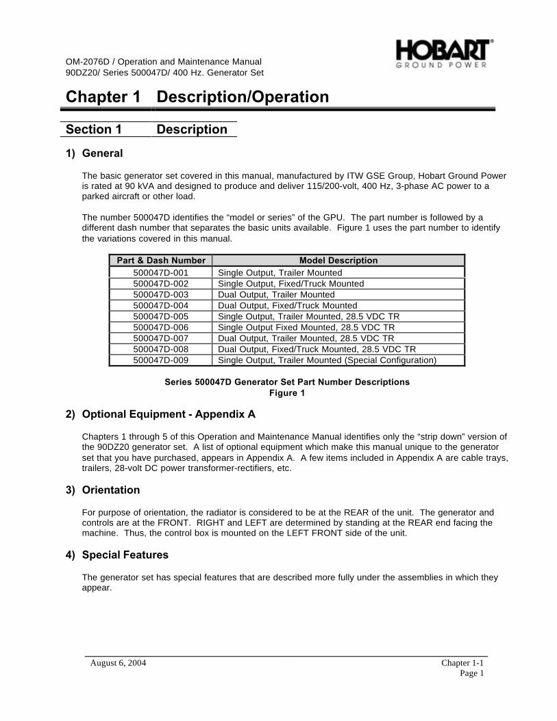
The basic generator set covered in this manual, manufactured by ITW GSE Group, Hobart Ground Poweris rated at 90 kVA and designed to produce and deliver 115/200-volt, 400 Hz, 3-phase AC power to aparked aircraft or other load.
The number 500047D identifies the “model or series” of the GPU. The part number is followed by adifferent dash number that separates the basic units available. Figure 1 uses the part number to identifythe variations covered in this manual.
Part & Dash Number Model Description500047D-001 Single Output, Trailer Mounted500047D-002 Single Output, Fixed/Truck Mounted500047D-003 Dual Output, Trailer Mounted500047D-004 Dual Output, Fixed/Truck Mounted500047D-005 Single Output, Trailer Mounted, 28.5 VDC TR500047D-006 Single Output Fixed Mounted, 28.5 VDC TR500047D-007 Dual Output, Trailer Mounted, 28.5 VDC TR500047D-008 Dual Output, Fixed/Truck Mounted, 28.5 VDC TR500047D-009 Single Output, Trailer Mounted (Special Configuration)
Series 500047D Generator Set Part Number DescriptionsFigure 1
2) Optional Equipment - Appendix A
Chapters 1 through 5 of this Operation and Maintenance Manual identifies only the “strip down” version ofthe 90DZ20 generator set. A list of optional equipment which make this manual unique to the generatorset that you have purchased, appears in Appendix A. A few items included in Appendix A are cable trays,trailers, 28-volt DC power transformer-rectifiers, etc.
3) Orientation
For purpose of orientation, the radiator is considered to be at the REAR of the unit. The generator andcontrols are at the FRONT. RIGHT and LEFT are determined by standing at the REAR end facing themachine. Thus, the control box is mounted on the LEFT FRONT side of the unit.
4) Special Features
The generator set has special features that are described more fully under the assemblies in which theyappear.
OM-2076D / Operation and Maintenance Manual90DZ20/ Series 500047D/ 400 Hz. Generator Set
August 6, 2004 Chapter 1-1Page 2
a) Protective Monitoring
The protective monitoring system receives signals from the fault sensing units in the generator outputcircuit and functions to cause the load to be disconnected from the generator if an abnormal conditionof voltage, frequency, or load develops.
b) Voltage Regulator
A microprocessor-type, adjustable voltage regulator provides automatic voltage regulation at theaircraft. The regulator is also adjustable for a variety of output cable sizes and lengths.
c) Engine Electronic Control Module
The engine is equipped with an electronic control module that monitors, records, and controls engineperformance.
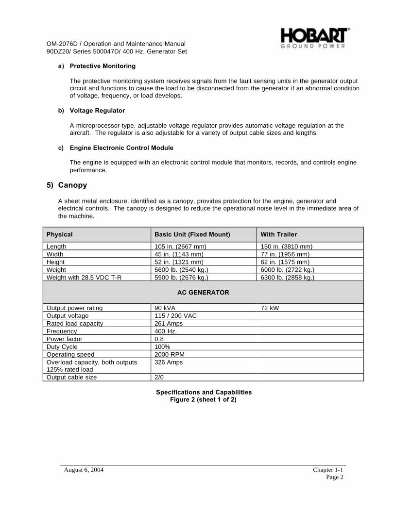
5) Canopy
A sheet metal enclosure, identified as a canopy, provides protection for the engine, generator andelectrical controls. The canopy is designed to reduce the operational noise level in the immediate area ofthe machine.
Physical Basic Unit (Fixed Mount) With Trailer
Length 105 in. (2667 mm) 150 in. (3810 mm)Width 45 in. (1143 mm) 77 in. (1956 mm)Height 52 in. (1321 mm) 62 in. (1575 mm)Weight 5600 lb. (2540 kg.) 6000 lb. (2722 kg.)Weight with 28.5 VDC T-R 5900 lb. (2676 kg.) 6300 lb. (2858 kg.)
AC GENERATOR
Output power rating 90 kVA 72 kWOutput voltage 115 / 200 VACRated load capacity 261 AmpsFrequency 400 Hz.Power factor 0.8Duty Cycle 100%Operating speed 2000 RPMOverload capacity, both outputs125% rated load
326 Amps
Output cable size 2/0
Specifications and CapabilitiesFigure 2 (sheet 1 of 2)
OM-2076D / Operation and Maintenance Manual90DZ20/ Series 500047D/ 400 Hz. Generator Set
August 6, 2004 Chapter 1-1Page 3
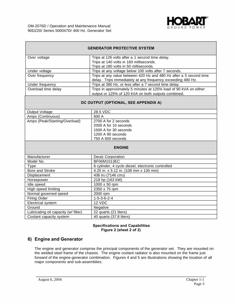
GENERATOR PROTECTIVE SYSTEM
Over voltage Trips at 126 volts after a 1 second time delay.Trips at 140 volts in 160 milliseconds.Trips at 180 volts in 50 milliseconds.
Under voltage Trips at any voltage below 100 volts after 7 seconds.Over frequency Trips at any value between 420 Hz and 480 Hz after a 5 second time
delay. Trips immediately at any frequency exceeding 480 Hz.Under frequency Trips at 380 Hz. or less after a 7 second time delay.Overload time delay Trips in approximately 5 minutes at 125% load of 90 kVA on either
output or 125% of 120 kVA on both outputs combined.
DC OUTPUT (OPTIONAL, SEE APPENDIX A)
Output Voltage 28.5 VDCAmps (Continuous) 600 AAmps (Peak/Starting/Overload) 2700 A for 2 seconds
2000 A for 10 seconds1500 A for 30 seconds1200 A 90 seconds750 A 600 seconds
ENGINE
Manufacturer Deutz CorporationModel No. BF06M1013ECType 6 cylinder, 4 cycle diesel, electronic controlledBore and Stroke 4.25 in. x 5.12 in. (108 mm x 130 mm)Displacement 436 in3 (7146 cm3)Horsepower 218 hp (163 kW)Idle speed 1000 ± 50 rpmHigh speed limiting 2350 ± 75 rpmNormal governed speed 2000 rpmFiring Order 1-5-3-6-2-4Electrical system 12 VDCGround NegativeLubricating oil capacity (w/ filter) 22 quarts (21 liters)Coolant capacity system 40 quarts (37.8 liters)
Specifications and CapabilitiesFigure 2 (sheet 2 of 2)
6) Engine and Generator
The engine and generator comprise the principal components of the generator set. They are mounted onthe welded steel frame of the chassis. The engine coolant radiator is also mounted on the frame justforward of the engine-generator combination. Figures 4 and 5 are illustrations showing the location of allmajor components and sub-assemblies.
OM-2076D / Operation and Maintenance Manual90DZ20/ Series 500047D/ 400 Hz. Generator Set
August 6, 2004 Chapter 1-1Page 4
a) Basic Engine
The basic engine is direct injected, 6-cylinder, electronically controlled, diesel rated at 218horsepower. See Figure 2 for specifications and capabilities.
b) Engine Manufacturer’s Equipment
As received from the engine manufacturer, the engine includes the following equipment, which ismore fully described in the engine manufacturer’s operation manual.
(1) Electrical System
The 12 VDC electrical generating and starting system include an alternator, voltage regulator,and starter with solenoid switch.
(2) Fuel Filter
The fuel filter is a spin-on disposable type, located on interior bulkhead located in the middle ofthe unit.
(3) Oil Filter
The engine oil filter is a spin-on, full-flow type, located on the left side of the engine near the front.
(4) Pre-programmed Electronic Engine Governor (EMR)
The EMR is a pre-programmed engine control module, mounted remotely on the interiorbulkhead.
c) Engine-cooling fan
The engine fan is designed to blow air outward through the radiator, rather than pulling the air inwardas a conventional fan does.
d) Factory Installed Equipment
This generator set is modified at the factory by the addition of the following equipment:
(1) Shut Down/Reset device
In addition to the other devices provided by the engine manufacturer, the factory also added anengine shutdown/reset feature.
a EMERGENCY SHUTDOWN/RESET SWITCH (S28)
The emergency shutdown switch has two purposes. One is to reset the starting circuitfollowing a failed starting sequence. The other is to provide instant manual shut off of thegenerator set by disconnecting power to the EMR through the control box. It is located on theleft side of the generator set near the control box (See Figure 3)

OM-2076D / Operation and Maintenance Manual90DZ20/ Series 500047D/ 400 Hz. Generator Set
August 6, 2004 Chapter 1-1Page 5
To operate the EMERGENCY SHUTDOWN/RESET SWITCH:
• Push button in until engine stops or until button travel stops• Pull the button back out to reset
b Coolant high temperature shutdown system
The coolant temperature shutdown system consists of a factory supplied temperature switch.This switch is monitored by the microprocessor on the EIB (“Engine Interface Board”) PCBoard, which will stop the engine if the temperature reaches 230º F (110º C).
c Oil pressure shutdown system
The oil pressure shutdown system consists of a factory supplied oil pressures switch. Thisswitch is monitored by the microprocessor on the EIB (“Engine Interface Board”) PC Board,which will stop the engine if the oil pressure is under 12 PSI (82.7 kPA).
(2) Radiator and Charge-Air-Cooler (CAC)
The radiator and charge-air-cooler is a two-piece type designed for long periods of operationwithout servicing. Refer to Section 2-1 for servicing procedure.
(3) Air cleaner (Figure 6)
The diesel engine air cleaner is so constructed that air enters through its cylindrical body, andthen is filtered in the process before being passed onto the engine turbo-charger assembly. Anair cleaner service indicator device is mounted on the air cleaner assembly to monitor the airflowinto the air cleaner. As the air cleaner becomes filled with dust, dirt, and carbon, the intakesystem airflow becomes increasingly restricted. This restriction causes a diaphragm inside theindicator to move toward an electrical contact. When the maximum allowable restriction level isreached, the circuit closes and the air cleaner indicator fault appears on the control panel faultdisplay to warn the operator that the air cleaner must be changed. The electrical indicatorautomatically resets when the restriction level drops sufficiently.
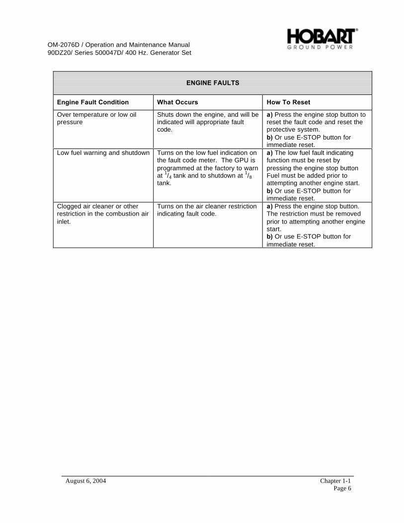
e) Engine faults
The following is a table listing faults, which may occasionally occur. Column two of the table explainswhat happens in the engine’s circuitry when the fault occurs, and column three tells how to return thegenerator set to service once the problem is solved. Refer to Chapter 2 for more details on all otherfaults.
OM-2076D / Operation and Maintenance Manual90DZ20/ Series 500047D/ 400 Hz. Generator Set
August 6, 2004 Chapter 1-1Page 6
ENGINE FAULTS
Engine Fault Condition What Occurs How To Reset
Over temperature or low oilpressure
Shuts down the engine, and will beindicated will appropriate faultcode.
a) Press the engine stop button toreset the fault code and reset theprotective system.b) Or use E-STOP button forimmediate reset.
Low fuel warning and shutdown Turns on the low fuel indication onthe fault code meter. The GPU isprogrammed at the factory to warnat 1/4 tank and to shutdown at 1/8tank.
a) The low fuel fault indicatingfunction must be reset bypressing the engine stop buttonFuel must be added prior toattempting another engine start.b) Or use E-STOP button forimmediate reset.
Clogged air cleaner or otherrestriction in the combustion airinlet.
Turns on the air cleaner restrictionindicating fault code.
a) Press the engine stop button.The restriction must be removedprior to attempting another enginestart.b) Or use E-STOP button forimmediate reset.
OM-2076D / Operation and Maintenance Manual90DZ20/ Series 500047D/ 400 Hz. Generator Set
August 6, 2004 Chapter 1-1Page 7
1 2
345
6
7
8 9
10
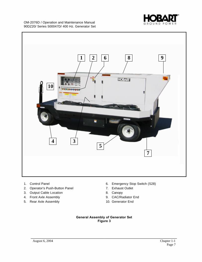
1. Control Panel2. Operator’s Push-Button Panel3. Output Cable Location4. Front Axle Assembly5. Rear Axle Assembly
6. Emergency Stop Switch (S28)7. Exhaust Outlet8. Canopy9. CAC/Radiator End10. Generator End
General Assembly of Generator SetFigure 3

OM-2076D / Operation and Maintenance Manual90DZ20/ Series 500047D/ 400 Hz. Generator Set
August 6, 2004 Chapter 1-1Page 8
1 2 3 45
6 7
8
9
10
1. Radiator / Charge-Air-Cooler2. Deutz 1013E Engine3. Air Cleaner4. Control Box5. Fuel Tank
6. Exhaust System7. Generator8. Inlet/Oulet Radiator Hoses9. Rear Axle10. Air Intake Heater (BH1)
Main Components of Generator Set (Right Side)Figure 4
OM-2076D / Operation and Maintenance Manual90DZ20/ Series 500047D/ 400 Hz. Generator Set
August 6, 2004 Chapter 1-1Page 9
1 2
3 4
5
6 78,910
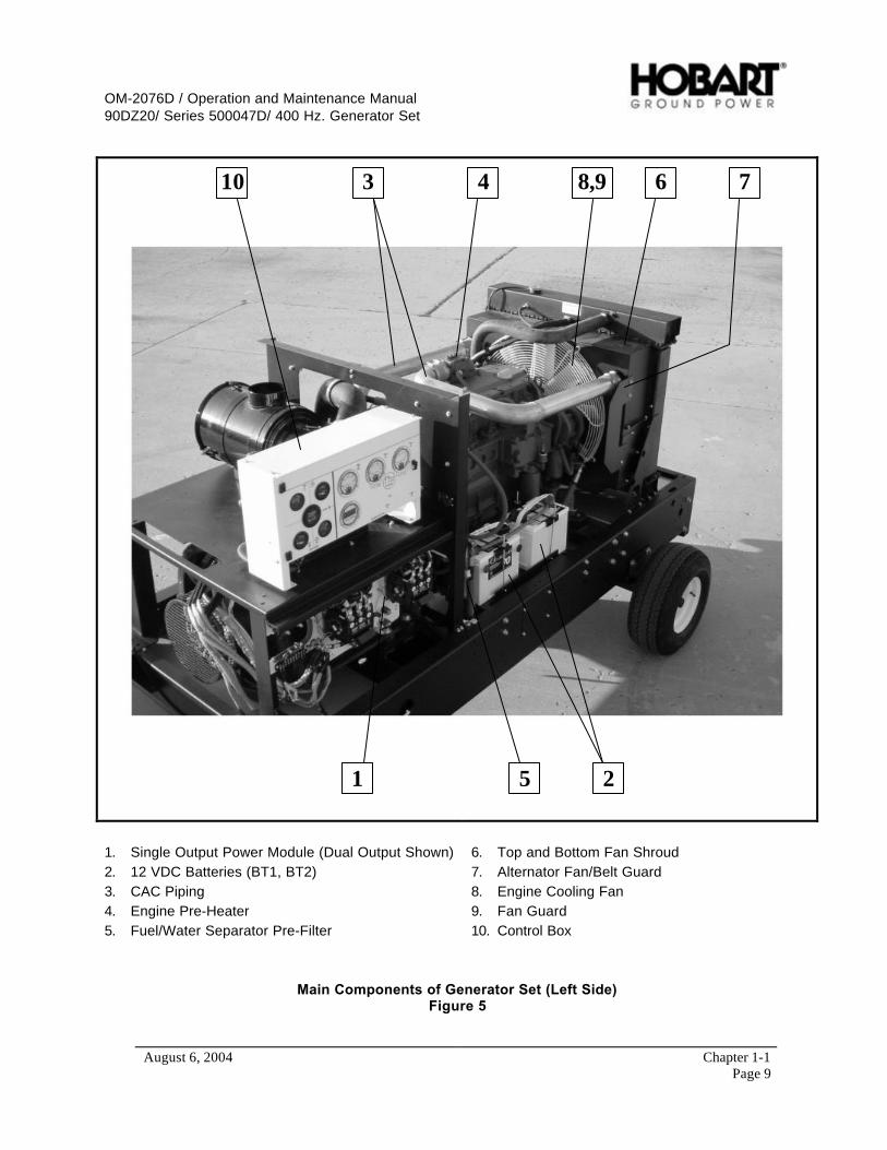
1. Single Output Power Module (Dual Output Shown)2. 12 VDC Batteries (BT1, BT2)3. CAC Piping4. Engine Pre-Heater5. Fuel/Water Separator Pre-Filter
6. Top and Bottom Fan Shroud7. Alternator Fan/Belt Guard8. Engine Cooling Fan9. Fan Guard10. Control Box
Main Components of Generator Set (Left Side)Figure 5

OM-2076D / Operation and Maintenance Manual90DZ20/ Series 500047D/ 400 Hz. Generator Set
August 6, 2004 Chapter 1-1Page 10
Service Indicator
Air Cleaner
Air Cleaner and Service IndicatorFigure 6
f) Generator
The 400 Hz generator is a brushless, revolving field, three-phase, alternating current type. Thegenerator set covered by this manual is a dual-bearing type. The front end of the rotor shaft extendsforward beyond the front bearing and is attached to the engine flywheel by a flexible couplingassembly. The rear end of the rotor shaft extends rearward beyond the rear bearing and into theexciter stator housing. The exciter rotor is mounted on this shaft extension with a key and is securedby a washer and 1/2-13 thread cap screw. A rectifier with six diodes is mounted on the exciter rotorand converts exciter AC output to DC for excitation of the generator revolving fields. The exciter DCoutput to the generator fields, and consequently the generator output, is controlled voltage regulatorPC board (REG). A centrifugal, radial-blade fan, which is part of the flexible coupling assembly,draws cooling air over all internal windings. Air enters at the exciter end and is discharged at thedrive end. The complete generator assembly is bolted to the engine flywheel housing.
7) Control Box Assembly
The control box is a sheet metal enclosure that houses and provides mounting facilities for engine andgenerator controls and monitoring equipment.
a) Control Panel (Figure 7 and 8)
The control system is divided into two sections. On the left side of the control panel, as one faces it,are engine meters. On the right side of the control panel are generator meters. Below the controlpanel are push-button switches for operating the engine and generator.
(1) Panel lights and panel light push-button switch (S74)
Meters are lighted from inside the control panel. The “LAMPS” push-button switch controls thelights.
(2) Engine hour meter (M4)
The hour meter is electrically driven from the 12 VDC battery system. The hour meter measuresand records the engine’s running time and will record up to 9999.9 hours on five revolving drums.It is only functional when the engine is running.

OM-2076D / Operation and Maintenance Manual90DZ20/ Series 500047D/ 400 Hz. Generator Set
August 6, 2004 Chapter 1-1Page 11
12
3 4
5
6 8 7,10 11,1010,12
139 15 1617
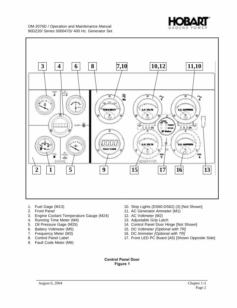
1. Fuel Gage (M13)2. Front Panel3. Engine Coolant Temperature Gauge (M24)4. Running Time Meter (M4)5. Oil Pressure Gage (M25)6. Battery Voltmeter (M5)7. Frequency Meter (M3)8. Control Panel Label9. Fault Code Meter (M6)
10. Strip Lights (DS60-DS62) (3) [Not Shown]11. AC Generator Ammeter (M1)12. AC Voltmeter (M2)13. Adjustable Grip Latch14. Control Panel Door Hinge [Not Shown]15. DC Voltmeter [Optional with TR]16. DC Ammeter [Optional with TR]17. Front LED PC Board (A5) [Shown Opposite Side]
Control Panel DoorFigure 7
OM-2076D / Operation and Maintenance Manual90DZ20/ Series 500047D/ 400 Hz. Generator Set
August 6, 2004 Chapter 1-1Page 12
1245678910 3
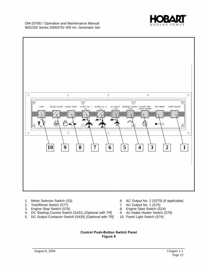
1. Meter Selector Switch (S3)2. Test/Reset Switch (S77)3. Engine Stop Switch (S76)4. DC Starting Current Switch (S431) [Optional with TR]5. DC Output Contactor Switch (S430) [Optional with TR]
6. AC Output No. 2 (S275) [if applicable]7. AC Output No. 1 (S75)8. Engine Start Switch (S24)9. Air Intake Heater Switch (S79)10. Panel Light Switch (S74)
Control Push-Button Switch PanelFigure 8
OM-2076D / Operation and Maintenance Manual90DZ20/ Series 500047D/ 400 Hz. Generator Set
August 6, 2004 Chapter 1-1Page 13
2
3
1
4
5
6
711 9 810
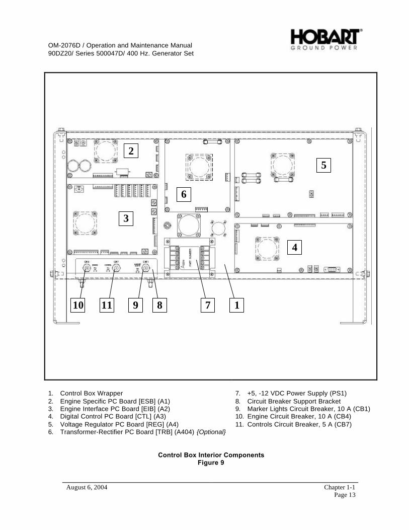
1. Control Box Wrapper2. Engine Specific PC Board [ESB] (A1)3. Engine Interface PC Board [EIB] (A2)4. Digital Control PC Board [CTL] (A3)5. Voltage Regulator PC Board [REG] (A4)6. Transformer-Rectifier PC Board [TRB] (A404) {Optional}
7. +5, -12 VDC Power Supply (PS1)8. Circuit Breaker Support Bracket9. Marker Lights Circuit Breaker, 10 A (CB1)10. Engine Circuit Breaker, 10 A (CB4)11. Controls Circuit Breaker, 5 A (CB7)
Control Box Interior ComponentsFigure 9
OM-2076D / Operation and Maintenance Manual90DZ20/ Series 500047D/ 400 Hz. Generator Set
August 6, 2004 Chapter 1-1Page 14
(3) Engine oil pressure gage (M24)
The oil pressure gage is an electrical type that is connected by a wire to an oil pressure sensorinstalled in the engine lubricating system. The range is 0 to 125 PSI (0 to 862 kPA).
(4) Engine ON indicating light (DS58)
When the engine is running at idle speed, a green indicating light, within the “ENGINE START”push button switch, flashes at a rate of 1 second on, 1 second off. When the engine is running atrated speed, the light will stay on continuously.
(5) Engine coolant temperature gage
The temperature gage is an electrical type that is connected by a wire to a water temperaturesensor installed in the engine cooling system. The gage indicates engine coolant temperature inthe range of 100-280 º F (38-138º C).
(6) “ENGINE START” push-button switch (S24)
The “ENGINE START” push-button switch, when pressed, connects 12 VDC power to the startersolenoid coil, which actuates the solenoid switch to connect power to the engine starting motor.The 12 VDC power is supplied directly to the engine EMR and the oil pressure shutdown switch isbypassed (This bypass is necessary for engine starting because the low oil pressure switch isCLOSED until the engine is running normally). The green indicator light with blink.
When pressed a second time, this push-button switch provides a signal to the EMR to adjust theengine speed to 2000 RPM. The green indicator light will glow continuously. At the same time, aground signal is provided to the regulator, enabling the generator to build up voltage for 400-Hzgenerator output. Pressing the push-button switch once more removes these signals and theengine reverts to idle speed and a blinking green indicator light.
(7) “ENGINE HEATER” push-button switch (S79)
The “ENGINE HEATER” push-button switch activates the standard cold starting aid (manifold airintake heater), which is totally controlled by the engine’s EMR. Once the heater is activated, theengine’s EMR will control the operation. The heater typically stays on for a period ofapproximately 30 seconds, which is indicated by the light on the push-button. When the lightgoes out, the engine is ready to start. Starting a cold engine without first warming the engine willlead to excessive white smoke exhaust and the engine may be hard to start.
(8) “ENGINE STOP” push-button switch (S76)
When the “ENGINE STOP” push-button switch is pressed, the red indicator will glow. Then a 3 -5 minute delay will occur to permit the turbo and other engine components to cool evenly. Afterthe delay, power is disconnected from the engine EMR causing the engine to shut down.
(9) Engine voltmeter (M5)
The ammeter indicates the direction and value of current flow from or to the 12 VDC battery. Itsgraduated 10 V to 16 V.

OM-2076D / Operation and Maintenance Manual90DZ20/ Series 500047D/ 400 Hz. Generator Set
August 6, 2004 Chapter 1-1Page 15
(10) Engine fuel gage (M13)
An electric fuel gauge receives its controlling signal from a sending unit in the fuel tank. 12 VDCoperating power is supplied to the fuel gauge when the “ENGINE START” push-button switch ispressed. The fuel level can also be checked when the unit isn’t running by pressing the panellight “LAMPS” push-button switch.
(11) Fault Code meter and “TEST/RESET” push-button switch (M6, S77)
The function of the fault code meter is to indicate to the operator, that an abnormal condition ofover voltage, under frequency, etc. occurred, which caused the protective monitoring system tofunction. When one of the circuits are activated, it shows the code on the fault code meter. Thefault will remain on for a short period of time or until the “TEST/RESET” push-button switch ispressed. Pressing the “TEST/RESET” push-button switch can also test the fault code meteroperation. A meter test should be performed only when disconnected from a load, as thecontactor(s) will open during the test cycle.
(12) Engine systems fault codes
Fault codes will be shown to warn the operator of abnormal engine operations that must becorrected. These indicators are over temperature, air cleaner restriction, low oil pressure, andlow fuel indication.
(13) AC Generator output monitors (meters)
Three instruments, a frequency meter, a voltmeter, and an ammeter monitor the generator output.The frequency meter is an analog type and indicates the frequency of the generator outputalternating current in the range of 360 to 440 Hz (cycles per second). The voltmeter indicates thegenerator output voltage in each phase-to-neutral (A-N, B-N and C-N) or phase-to-phase (A-B, B-C and C-A) as selected by the “METER SELECT” switch. The voltmeter has a scale of 0 to 300V. The ammeter has a scale of 0 to 500 A. The amperage value in each of the three phasesmay be read on the ammeter by selecting the desired phase with “METER SELECT” switch. Theammeter current transformers, located in the output power module circuit, lower the output loadcurrent to a lesser value, of definite ratio, which is sent to the Voltage Regulator PC Board (REG).The ammeter dial scale is numbered so that the pointer will indicate the true load current value.
(14) Load contactor indicating lights [Yellow # 1 and Orange # 2] (S75, S275)
Indicating lights within the respective contactor control push-button switches (“OUTPUT NO. 1”and or “OUTPUT NO. 2” , if applicable) glow when the circuit is energized, indicating that poweris available at the plug. When the load contactor opens for any reason, the light is turned OFF.
(15) Front LED Display (A5)
The front LED display signifies to the operator which voltage (A-N, A-B, etc…) and amperage areshown on the meters, as well as, when “EF BY-PASS” is present or bypassed. This “EF BY-PASS” indicator serves to warn the operator that if the plug interlock system was by-passed anyexposed cable may be live.

OM-2076D / Operation and Maintenance Manual90DZ20/ Series 500047D/ 400 Hz. Generator Set
August 6, 2004 Chapter 1-1Page 16
(16) DC Generator output monitors (meters) [Optional with TR, Reference Appendix A]
Two instruments, a voltmeter and an ammeter, monitor and display the transformer-rectifier’soutput. The voltmeter and ammeter meters are both analog type and indicate the output voltagefrom 0 to 50 VDC and the amperage from 0 to 2500 A.
(17) “STARTING CURRENT” Switch (S431) [Optional with TR, Reference Appendix A]
Each time the “STARTING CURRENT” push-button switch is pressed, the BLUE indicator willglow. The present current limiting amperage setting will be displayed on the fault code meter fora short time delay, before incrementing, at 100 A increments, up to 2500 A. Once 2500 A hasbeen reached, the incrementing will start over from the beginning.
(18) “DC OUTPUT” Contactor Switch (S430) [Optional with TR, Reference Appendix A]
Each time the “DC OUTPUT” push-button switch is pressed, the BLUE indicator will glow whenthe circuit is energized, indicating that power is available at the plug. When the load contactoropens for any reason, the light is turned OFF.
b) Control Box Interior Components (Figure 9)
(1) EF Bypass switches (located on CTL)
For each load contactor circuit, a single-pole, single-throw “EF1 BYPASS” for “OUTPUT 1” (or“EF2 BYPASS” for “OUTPUT 2” , if applicable) provides a means of bypassing the 28 VDCinterlock circuit for the contactor when supplying power to a load bank or to an aircraft notequipped with a plug interlock system.
(2) Regulated-diagnostic switch (located on the REG)
When the “REGULATED/DIAGNOSTIC” switch is in the “REGULATED” (down) position, thegenerator output voltage is regulated by the PC board for 115/200 VAC output to an aircraft.When this switch is placed in the “DIAGNOSTIC” (up) position, 12 VDC is applied to thegenerator exciter with the engine running at rated RPM, in order to check the operation of thegenerator. This is done to determine if a particular power output malfunction is caused by adefective generator or by a defective voltage regulator. When this switch is in theMAINTENANCE position, no current is supplied to the generator exciter. In this condition, a low-level, unregulated voltage of approximately 30 VAC will be produced at the generator outputterminals due to the residual magnetism of the exciter.
(3) Circuit breakers (CB1, CB4, CB7)
A 10-ampere “ENGINE” circuit breaker, protects the 12 VDC engine electrical and fault circuits,and another 10-ampere “MARKER LIGHTS” circuit breaker protects the 12 VDC lighting system.A 5-ampere “CONTROL” circuit breaker protects the 12 VDC control system.
(4) Digital Control PC Board [CTL] (A3)
The digital control PC board (see Figure 10) is the center for all communications throughout theentire control system. All push-button panel commands run through the digital control PC boardand communicates the commands to the appropriate area (i.e. other PC boards) in the controlsystem. The digital control PC board also controls the real time clock, monitors the over/undervoltage and overload protection, push-button panel indicator lights, generator output meters, EFbypass switches, and communicates with the optional service tool.

OM-2076D / Operation and Maintenance Manual90DZ20/ Series 500047D/ 400 Hz. Generator Set
August 6, 2004 Chapter 1-1Page 17
(5) Engine Interface PC Board [EIB] (A2)
The EIB (see figure 11) is common between all engine models and monitors coolant temperature,oil pressure, battery voltage, and fuel tank level monitoring. The EIB is also responsible for themonitoring the warning switches for high coolant temperature, low oil pressure, high airrestriction, and low coolant level (optional). The warning switches signal the EIB when a faultoccurs, which then the EIB relays this information to the CTL. The CTL will issue the commandto the system that fits the fault event.
The EIB also controls the power distribution in the control system, hour meter, lights, and theengine starter operation.
EF1 Bypass
EF2 Bypass (if applicable)
PC Board Software
Service Tool Connector
J54 Connector
Digital Control PC BoardFigure 10
(6) Engine Specific PC Board [ESB] (A1)
The ESB (see figure 12) is unique only to the engine model used in the GPU purchased. TheESB is the primary interface between the control system and the engine’s electronic controlmodule. When the CTL senses the engine start button has been pressed it signals to the ESB,which then communicates to the engine control module what mode of operation is required (idleor rated speed).
The ESB controls the “FREQUENCY ADJUST” switch that is used to enable the “FREQUENCYADJUST ENABLE/DISABLE” potentiometer to test the over/under frequency fault limits of thegenerator set system. The ESB also controls the “DATA REQUEST” button and diagnosticindicator light to read the engine’s EMR diagnostic error codes.

OM-2076D / Operation and Maintenance Manual90DZ20/ Series 500047D/ 400 Hz. Generator Set
August 6, 2004 Chapter 1-1Page 18
J51 Connector
Starter Disable/Enable
PC Board Software
Engine Interface PC BoardFigure 11
J52 Connector
Engine Status Light PC Board Software
Engine Status Switch Frequency Adjustment &Enable/Disable Switch
Engine Specific PC BoardFigure 12

OM-2076D / Operation and Maintenance Manual90DZ20/ Series 500047D/ 400 Hz. Generator Set
August 6, 2004 Chapter 1-1Page 19
Regulated/Diagnostic J53 Connector
Voltage Adjustment, Coarse
Voltage Adjustment, Fine LDC Control
PC Board Software
Voltage Regulator PC BoardFigure 13
(7) Voltage regulator PC board [REG] (A4)
This voltage regulator PC board (see Figure 13) is designed to provide voltage regulation for athree-phase, four-wire, 115/200-volt, 400-Hz brushless alternator. This regulator provides fieldexcitation power as required to meet varying alternator load conditions to hold the alternatorvoltage constant. In addition, the voltage regulator PC board circuitry provides line dropcompensation. Any deviation of the alternator voltage from its set, regulated level is sensed atthe voltage regulator PC board. The sensing signal is compared to a reference signal, and, withassociated circuitry, varies the field power supplied to the rotary exciter.
a When the machine is started, and the engine is at rated speed, the rotary exciter is excitedfrom alternator residual magnetism through the half-wave rectifier-bridge, located on thevoltage regulator PC board assembly. As the rotary exciter voltage increases, alternatorexcitation increases and the alternator voltage builds up. The sensing circuit of the voltageregulator PC board then compares the input voltage to a reference voltage and adjusts thefield power of the rotary exciter to bring the voltage into regulation limits.

OM-2076D / Operation and Maintenance Manual90DZ20/ Series 500047D/ 400 Hz. Generator Set
August 6, 2004 Chapter 1-1Page 20
b When the alternator is loaded, its terminal voltage decreases, lowering the rectified three-phase voltage of the voltage sensing circuit. The sensing voltage is low in respect to itsreference voltage, causing the voltage regulator PC circuitry to increase the power to the fieldof the rotary exciter. The alternator voltage increases until the voltage returns to its regulatedvalue.
c When a load is removed from the alternator, the alternator voltage rises. The rectified three-phase voltage-sensing signal increases, causing this signal to be higher than the referencesignal. The associated voltage regulator circuitry causes the field power of the rotary exciterto decrease, lowering the alternator voltage until the voltage returns to regulated value. Theline drop voltage compensation circuit consists of a current transformer on each phase of theload circuit, and fixed resistance in parallel with each current transformer. The currenttransformers detects the magnitude of current flowing through the power cables from thealternator to its load and feeds a signal into the voltage regulator PC board. The PC boardprocesses this signal to change the output voltage proportional to the current draw. Theregulator output increases slightly so that the alternator output voltage is equal to theregulated voltage plus the voltage drop in the lines. The line drop compensationpotentiometer may be adjusted to match exactly the voltage drop of the power cablescarrying the load current.
The under/over frequency protection, EF signal, and lost neutral detection are also monitored bythe REG and will signal the CTL when a fault has occurred. The CTL issues the appropriatecommand that corresponds to the fault.
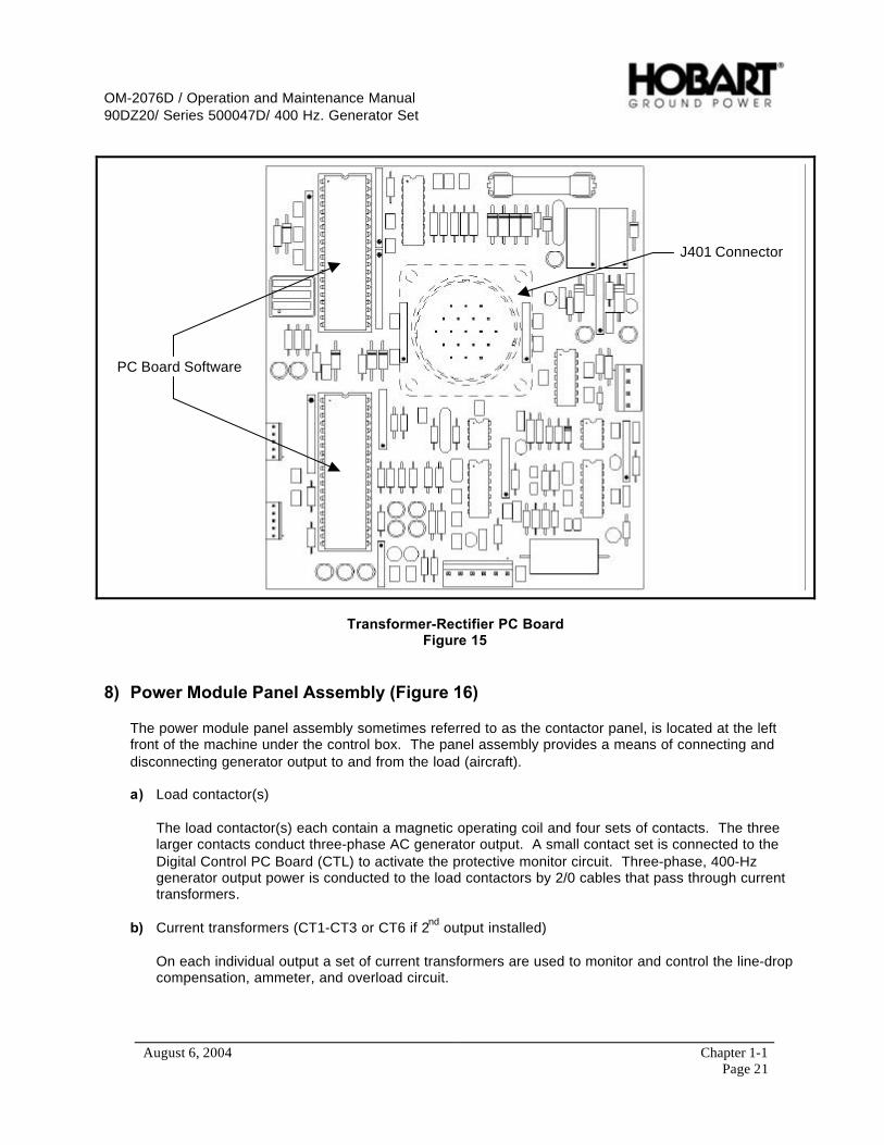
(8) Transformer-Rectifier PC Board [TRB] (A404) {Optional with TR, Reference Appendix A}
The TRB PC Board (see Figure 15) is only used when the optional 28.5 VDC transformer-rectifierassembly is installed. The TR monitors the output voltage, output current, controls the input andoutput contactors, and monitors all fault events associated with the DC output. When a fault eventdoes occur the TRB relays this information to the CTL. The CTL will issue the command to thesystem that fits the fault event.
(9) +5, -12 VDC Power Source (PS1)
Supplies the internal power distribution of +5 VDC and –12 VDC into the control system.
Control System Power SourceFigure 14
OM-2076D / Operation and Maintenance Manual90DZ20/ Series 500047D/ 400 Hz. Generator Set
August 6, 2004 Chapter 1-1Page 21
PC Board Software
J401 Connector
Transformer-Rectifier PC BoardFigure 15
8) Power Module Panel Assembly (Figure 16)
The power module panel assembly sometimes referred to as the contactor panel, is located at the leftfront of the machine under the control box. The panel assembly provides a means of connecting anddisconnecting generator output to and from the load (aircraft).
a) Load contactor(s)
The load contactor(s) each contain a magnetic operating coil and four sets of contacts. The threelarger contacts conduct three-phase AC generator output. A small contact set is connected to theDigital Control PC Board (CTL) to activate the protective monitor circuit. Three-phase, 400-Hzgenerator output power is conducted to the load contactors by 2/0 cables that pass through currenttransformers.
b) Current transformers (CT1-CT3 or CT6 if 2nd output installed)
On each individual output a set of current transformers are used to monitor and control the line-dropcompensation, ammeter, and overload circuit.
OM-2076D / Operation and Maintenance Manual90DZ20/ Series 500047D/ 400 Hz. Generator Set
August 6, 2004 Chapter 1-1Page 22
(1) Line-Drop Compensation
The current transformers detects the magnitude and power factor of current flowing fromgenerator to load. They feed a signal to the voltage regulator that interprets the signal and altersthe exciter field current as required to maintain a constant predetermined voltage at the load.
(2) Ammeter
The current transformers convert a current signal to a voltage signal, which is sent to the VoltageRegulator PC Board (REG). The ammeter is really a voltmeter graduated and numbered inamperes to show current proportional to the voltage signal received.
When there is overload on the output for more than 5 minutes (load exceeding 326 amperes peroutput or 125% of rated load), the main overload sensing circuit sends signals the load thecontactor(s) circuit to open both load contactors.
(3) Overload, No 1 and/or No. 2 output (if applicable)
On each individual output the current transformers converts a current signal to a voltage signal.The voltage signal is sent to the ammeter and to the overload monitoring circuit for that output.The overload monitoring circuit will open the contactors when the output current reaches 125% ofthe normal rated output current. The monitoring circuit moniters each individual output, as wellas, the overall current for a dual output machines.
The following is a list of overload module characteristics:
• At 125% load the module will function in 5 minutes.• At 150% load the module will function in 30 seconds.• AT 200% load the module will function in 10 seconds.
NOTE: The overload protective system will function when any phase carries 123% to 127% ofrated load. All times are plus or minus 25% and are non-adjustable.
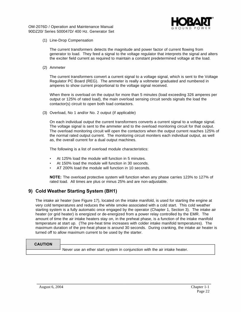
9) Cold Weather Starting System (BH1)
The intake air heater (see Figure 17), located on the intake manifold, is used for starting the engine atvery cold temperatures and reduces the white smoke associated with a cold start. This cold weatherstarting system is a fully automatic once engaged by the operator (Chapter 1, Section 3). The intake airheater (or grid heater) is energized or de-energized from a power relay controlled by the EMR. Theamount of time the air intake heaters stay on, in the preheat phase, is a function of the intake manifoldtemperature at start up. (The pre-heat time increases with colder intake manifold temperatures). Themaximum duration of the pre-heat phase is around 30 seconds. During cranking, the intake air heater isturned off to allow maximum current to be used by the starter.
CAUTIONNever use an ether start system in conjunction with the air intake heater.

OM-2076D / Operation and Maintenance Manual90DZ20/ Series 500047D/ 400 Hz. Generator Set
August 6, 2004 Chapter 1-1Page 23
Output Cable Connection PointsOutput Contactor # 1 (S75)
Output Contactor # 2 (S275)Location (if applicable)Current Transformers (CT1-CT3)Generator Lead Connection Point
Output Power Module ComponentsFigure 16

OM-2076D / Operation and Maintenance Manual90DZ20/ Series 500047D/ 400 Hz. Generator Set
August 6, 2004 Chapter 1-1Page 24
Intake Heater
CAC Intake End
Air Intake HeaterFigure 17

OM-2076D / Operation and Maintenance Manual90DZ20/ Series 500047D/ 400 Hz. Generator Set
August 6, 2004 Chapter 1-2Page 1
Section 2 Preparation for Use, Storage, or Shipping
1) Preparation for Use
a) Inspection/Check
Inspect the unit thoroughly prior to operation.
(1) Remove blocking, banding, ties, and other securing material.
(2) Inspect exterior for shipping damage such as broken lights, damaged sheet metal, etc.
(3) Open all canopy doors and inspect interior for foreign material such as rags, tools, shippingpapers, etc.
(4) Check fuel, coolant, oil hoses and connections for visible leaks. Visually inspect the compartmentfloor and ground surface under the unit for signs of leakage. If leaks are found, correct bytightening hose clamps, tube fitting, etc., as required.
(5) Check security of generator set retaining components.
(6) Check the following for sufficient quantity:
a Fuel
Press “LAMPS” push-button button to energize fuel gage when engine is stopped. Fuel issupplied from a customer-furnished source.
NOTE: For recommended fuel specifications refer to the Engine Manufacturers Operation andMaintenance Manual provided with this manual.
b Engine coolant
Remove radiator cap to check coolant level. Coolant level should be at the bottom of the fillerneck.
CAUTIONBE SURE the cooling system antifreeze solution is adequate to protect below thelowest temperature expected.
NOTE: For antifreeze protection, use a solution of 50% permanent antifreeze (Ethylene glycol) and50% clean water.
ENGINE OIL AND COOLANT CAPACITIES
Lubricating oil capacity (w/ filter) 22 quarts (21 liters)Coolant capacity system 40 quarts (37.8 liters)
Figure 1
OM-2076D / Operation and Maintenance Manual90DZ20/ Series 500047D/ 400 Hz. Generator Set
August 6, 2004 Chapter 1-2Page 2
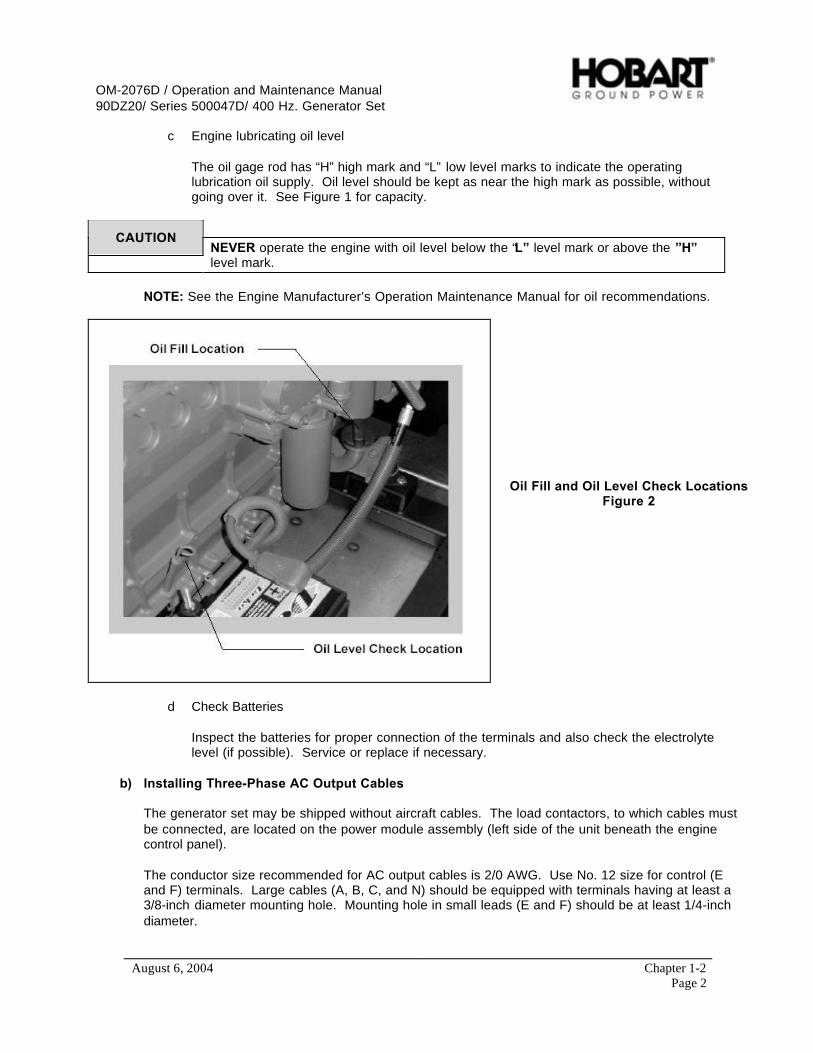
c Engine lubricating oil level
The oil gage rod has “H” high mark and “L” low level marks to indicate the operatinglubrication oil supply. Oil level should be kept as near the high mark as possible, withoutgoing over it. See Figure 1 for capacity.
CAUTIONNEVER operate the engine with oil level below the “L” level mark or above the ”H”level mark.
NOTE: See the Engine Manufacturer’s Operation Maintenance Manual for oil recommendations.
Oil Fill and Oil Level Check LocationsFigure 2
d Check Batteries
Inspect the batteries for proper connection of the terminals and also check the electrolytelevel (if possible). Service or replace if necessary.
b) Installing Three-Phase AC Output Cables
The generator set may be shipped without aircraft cables. The load contactors, to which cables mustbe connected, are located on the power module assembly (left side of the unit beneath the enginecontrol panel).
The conductor size recommended for AC output cables is 2/0 AWG. Use No. 12 size for control (Eand F) terminals. Large cables (A, B, C, and N) should be equipped with terminals having at least a3/8-inch diameter mounting hole. Mounting hole in small leads (E and F) should be at least 1/4-inchdiameter.

OM-2076D / Operation and Maintenance Manual90DZ20/ Series 500047D/ 400 Hz. Generator Set
August 6, 2004 Chapter 1-2Page 3
To install AC output cables proceed as follows:
(1) Open control box door of the generator set and remove the lower panel.
(2) Remove Plexiglas cover in front of the power module assembly.
(3) Remove the cover panel on the cable tray covering the cable clamps.
(4) Loosen screws on cable clamps.
(5) Route cables through cable clamps, and up to the load side of the load contactor(s).
(6) Connect the phase cable terminal lugs to the appropriate terminal studs on the contactor(s): cablelug “A” to terminal stud “A”, “B” to “B”, and “C” to “C”.
(7) Connect the cable’s neutral terminal lug securely to the neutral (ground) stud on the powermodule assembly.
(8) Connect the “E” and “F” cables to the “E” and “F” studs on the power module assembly.
(9) Tighten clamp screws securely, but avoid damage to cable insulation.
(10) Replace Plexiglas cover panel, lower panel, and close canopy door.
2) Preparation for Storage
When a generator set is to be stored or removed from operation, special precautions should be taken toprotect the internal and external parts from rust, corrosion, and gumming in the engine fuel system.
a) General
Pull all circuit breakers and/or disconnect battery negative terminal.
(1) The unit should be prepared for storage as soon as possible after being removed from service.
(2) The unit should be stored in a building which is dry and which may be heated during wintermonths.
(3) Moisture absorbing chemicals (Factory Part No. 76A1354-001) are available for use whereexcessive dampness is a problem; however, the unit must be completely packaged and sealed ifmoisture absorbing chemicals are to be effective.
b) Temporary Storage
When storing the unit for 30 days or less, prepare as follows:
(1) Lubricate the unit completely in accordance with instructions in Section 2-2. This will includechanging engine oil, and all filter elements.
(2) Start the engine and operate for about two minutes so that all internal engine components will becoated with new oil.
NOTE: Do not drain the fuel system or crankcase after this run.

OM-2076D / Operation and Maintenance Manual90DZ20/ Series 500047D/ 400 Hz. Generator Set
August 6, 2004 Chapter 1-2Page 4
(3) Make certain the cooling system antifreeze solution is adequate to protect below the lowesttemperatures expected during the storage period. Be sure the solution is thoroughly mixed.
(4) Clean the exterior of the engine. Dry with clean rags and compressed air.
(5) Seal all engine openings. Use a waterproof, vapor proof material that is strong enough to resistpuncture damage from air pressures.
c) Long Time Storage (Over 30 Days)
To protect the generator and other electrical components, the complete unit should be packagedusing moisture proof packaging material and sealing material. Place containers of moistureabsorbing chemicals (Factory Part No. 76A-1354-001) in the unit before packaging. The unit may bestored for long periods with no special preparation if it is possible to operate the engine once eachweek. When starting once a week proceed as follows:
(1) Make certain the cooling system is adequately protected.
WARNINGENSURE adequate ventilation before starting the engine.
(2) Start the engine and operate under full load until coolant temperature has reached at least 176ºF(80ºC).
(3) While the engine is running, ensure that normal operating controls are in good working conditionbefore shutdown and storage. If weekly operation is not possible, contact the nearest enginemanufacturer distributor for instructions.
3) Preparation for Shipment
a) Disconnect battery negative terminal before shipping.
b) During long shipments, vibration, jolting, etc may loosen the generator set retaining hardware.
CAUTIONWhen shipping the unit, provide sufficient retaining materials to ensure the generatorset cannot roll out or off the vehicle in which it is being transported.
NOTE: It is suggested that strong banding be used to secure the generator set, or a strong steel barbe either welded or bolted across the front of the generator set frame.

OM-2076D / Operation and Maintenance Manual90DZ20/ Series 500047D/ 400 Hz. Generator Set
August 6, 2004 Chapter 1-3Page 1
Section 3 Operation
1) General
This section contains information and instructions for the safe and efficient operation of the equipment.Operating instructions are presented in step-by-step sequence of procedures to be followed in supplying400-Hz power.
NOTE: Read ALL of the operating instructions before attempting to operate the equipment.
WARNINGEar protection equipment may be necessary when working close to this equipment.
2) 400 Hz. Operating Procedure
a) Pre-start inspection
(1) Be sure the fuel shutoff valve on the unit is open.
(2) Ensure 12 VDC power is available to the engine starting system.
(3) Check the engine and generator compartments to make certain they are free of rags or otherforeign materials.
(4) Make certain there is sufficient lubricating oil and coolant in the engine.
(5) Check that all circuit breakers are reset.
(6) Make certain the “STARTER ENABLE/DISABLE” switch is enabled, and the “FREQUENCYADJUST” switch is disabled.
b) Normal Engine Starting Procedures
Engine starting procedures are outlined below. The engine’s operating controls and monitoringinstruments are illustrated in Figure 1 and 2.
CAUTIONRefer to operating instructions in the engine manufacturer’s operation manual, whenstarting engine for the first time.
NOTE: The engine manufacturer’s operation manual is provided with this manual.
(1) If illumination is required, press “LAMPS” push-button switch one time. Pressing this buttonswitch also activates the fuel gage.
(2) On days when the ambient temperatures are below 60° F, press the “ENGINE HEATER” push-button to engage the air intake heater prior to starting the engine. The light in the button willilluminate when the intake heater is engaged (if the light does not illuminate, the engine is readyto start) and will go off when the intake heater is disengaged, thus signifying the engine is readyto start.
OM-2076D / Operation and Maintenance Manual90DZ20/ Series 500047D/ 400 Hz. Generator Set
August 6, 2004 Chapter 1-3Page 2
12
3 4
5
6 8 7,10 11,1010,12
139 15 1617
1. Fuel Gage (M13)2. Front Panel3. Engine Coolant Temperature Gauge (M24)4. Running Time Meter (M4)5. Oil Pressure Gage (M25)6. Battery Voltmeter (M5)7. Frequency Meter (M3)8. Control Panel Label9. Fault Code Meter (M6)
10. Strip Lights (DS60-DS62) (3) [Not Shown]11. AC Generator Ammeter (M1)12. AC Voltmeter (M2)13. Adjustable Grip Latch14. Control Panel Door Hinge [Not Shown]15. DC Voltmeter [Optional with TR]16. DC Ammeter [Optional with TR]17. Front LED PC Board (A5) [Shown Opposite Side]
Control Panel DoorFigure 1

OM-2076D / Operation and Maintenance Manual90DZ20/ Series 500047D/ 400 Hz. Generator Set
August 6, 2004 Chapter 1-3Page 3
1245678910 3
1. Meter Selector Switch (S3)2. Test/Reset Switch (S77)3. Engine Stop Switch (S76)4. DC Starting Current Switch (S431) [Optional with TR]5. DC Output Contactor Switch (S430) [Optional with TR]
6. AC Output No. 2 (S275) [if applicable]7. AC Output No. 1 (S75)8. Engine Start Switch (S24)9. Air Intake Heater Switch (S79)10. Panel Light Switch (S74)
Control Push-Button Switch PanelFigure 2

OM-2076D / Operation and Maintenance Manual90DZ20/ Series 500047D/ 400 Hz. Generator Set
August 6, 2004 Chapter 1-3Page 4
CAUTIONNever use an ether start system in conjunction with the air intake heater.
(3) Press the green “ENGINE START” push-button switch and hold until engine starts. The enginewill start at idle speed, and the green light in the “ENGINE START” push-button switch will flashto indicate that power is available to the engine’s ECM circuit.
CAUTIONDo not attempt to bring to rated speed for at least 5 seconds after engine starts.Damage to the starter and flywheel will result.
CAUTIONIf the engine fails to start within 5 seconds, the control system will automaticallydisable the starting motor and indicate a low oil pressure fault. The emergency stopswitch must be pressed to reset the control system and allow another starting attempt.If the engine fails to start after four attempts, an inspection should be made todetermine the cause.
If the engine fires sufficiently to disengage the starter gear, but does not start, allowthe starting motor to come to a complete stop before attempting to engage the starteragain, then press the start push button switch.
(4) Check oil pressure to make certain that it is normal, and observe all other engine instruments fornormal operation.
(5) Allow engine to idle and warm for 3 - 5 minutes before bringing it up to rated speed.
CAUTIONTo eliminate the possibility of wet stacking (See Appendix A), DO NOT allow theengine to idle for long periods of time.
c) Failed Starting Procedure
In the event that the engine fails to start, the circuitry must be reset before the next attempt. To dothis:
(1) Push the red “EMERGENCY STOP/RESET BUTTON” on the control box door to the right of thecontrol panel.
(2) Pull the red “EMERGENCY STOP/RESET BUTTON” back out before the next attempt to startthe generator set.
d) Power Delivery
(1) Press “ENGINE START” push button switch a second time to bring engine from idle speed torated speed. The ECM will immediately increase engine speed to 2000 RPM and maintain it.The voltage build-up will occur automatically. Also the green indicating light in the “ENGINESTART” push-button switch will glow continuously.

OM-2076D / Operation and Maintenance Manual90DZ20/ Series 500047D/ 400 Hz. Generator Set
August 6, 2004 Chapter 1-3Page 5
(2) Observe generator instruments. The frequency meter should indicate exactly 400 Hz. With the“METER SELECT” push button switch set to read any line-to-neutral position, (A-N, B-N, or C-N), the voltmeter should read 115 volts. With the “METER SELECT” push button switch set toany line-to-line position, (A-B, B-C, or C-A), the voltmeter should read 200 volts.
(3) The final step in delivering power is closing one or both of the load contactors. When theinstruments indicate satisfactory frequency and voltage values, close either load contactor (orboth load contactors) by momentarily pressing the load contactor(s) (“OUTPUT NO. 1” or“OUTPUT NO. 2”, if applicable) push button switch. The yellow or orange indicating light of thepush button switch that is pressed will glow continuously, indicating that the load contactor isclosed and power is available at the aircraft.
(4) Early in the power delivery run it is recommended that the operator check output voltage andcurrent in each of the three phases. Use the “METER SELECT” push button switch to select theeither the line-to-line or line-to-neutral voltage. If the load is changing, it is good operatingpractice to observe the instruments until load conditions stabilize.
CAUTIONNEVER press the test/reset push button switch while power is being delivered.The contactors will open and power to the aircraft will be suddenly interrupted.
(5) A condition of over-voltage, under-voltage, under-frequency, over-frequency, or overload in theoutput circuit will automatically open the load contactor and display a fault code to signal theoperator which of the above faults caused the protective monitor system to operate. After thefault has been corrected, press the “TEST/RESET” push-button switch to reset the protectiverelay system. Proceed with power delivery by operating the load contactor push button switch.
WARNINGNEVER disconnect the output cable while power is being delivered. Outputcontactors must be open prior to removal of the cable from the aircraft.
CAUTIONThe generator set must be shut down so that the failed power delivery problems canbe diagnosed. Only licensed technicians should work on this generator set.
e) Failed Power Delivery
If the contactor indicating light should go out as soon as the push button switch is released, and afault code is displayed indicating that 28.5 VDC interlock signal is not being supplied from the aircraftto the plug interlock relay, correct the condition and again press the load contactor(s) (“OUTPUT NO.1” or “OUTPUT NO. 2” , if applicable) push button switch.
The “REGULATED/DIAGNOSTIC” switch (located on the VR1) must be set to “NORMAL” for powerdelivery.
The “OUTPUT NO. 1” (or “OUTPUT NO. 2”, if applicable) “EF BY-PASS ON/OFF” switch (locatedon the CTL) must be set to “ON” position.
See section 2-4 for other No. 1 (or No. 2, if applicable) Load Contactor Operating Circuit for additionaltroubleshooting procedures.

OM-2076D / Operation and Maintenance Manual90DZ20/ Series 500047D/ 400 Hz. Generator Set
August 6, 2004 Chapter 1-3Page 6
f) Discontinue Power Delivery with Unit Shutdown
(1) Normal conditions
a Push the load contactor(s) (“OUTPUT NO. 1” or “OUTPUT NO. 2”, if applicable) pushbutton switch to open the contactor. The indicating light (yellow or orange depending on thecontactor used) on that switch will go OFF immediately to indicate that the load contactor hasopened and power is no longer being delivered to the aircraft. The engine will remain atrated speed.
b Push the red “ENGINE STOP” push-button switch once to bring the engine down to idlespeed. This will begin the automatic shutdown sequence to shut off the engine, gauges,lights, etc., after approximately 3 - 5 minutes.
c Disconnect output cable from aircraft after engine is at idle speed only.
(2) Emergency conditions
a Depress the “EMERGENCY STOP BUTTON” located on the control box door to the right ofthe control panel. When pushed this button instantly shuts the generator set off and must bepulled back out to reset itself for restarting the generator set.
CAUTIONDo not use the “EMERGENCY STOP BUTTON” button as a normal shutdown device.Damage to the engine turbo charger may result without proper cooling time. Use the“ENGINE STOP” push-button for all normal engine shutdowns.
3) DC Operating Procedure (Optional, See Appendix A)
The 28.5 VDC transformer-rectifier is an optional add-on to the GPU. See Appendix A for more details onthe operation of the transformer-rectifier.

OM-2076D / Operation and Maintenance Manual90DZ20/ Series 500047D/ 400 Hz. Generator Set
August 6, 2004 Chapter 2-1Page 1
Chapter 2 Service and Troubleshooting
Section 1 Maintenance Inspection/Check
1) General
To make certain the generator set is always ready for operation, it must be inspected and maintainedregularly and systematically so that defects may be discovered and corrected before they result in seriousdamage to components, or failure of the equipment.
WARNINGSTOP operations at once if a serious or possibly dangerous fault is discovered.
2) Maintenance Schedule
a) General
A periodic maintenance schedule should be established and maintained. A suggested schedule isprovided in Figure 1 on the following pages. It may be modified, as required to meet varyingoperating and environmental conditions. It is suggested that generator set and vehicle inspections becoordinated as much as possible.
b) Maintenance Schedule Check Sheet
It is strongly recommended that the customer use a maintenance schedule check sheet such as theone in engine manufacture’s operation manual. The check sheet will provide a record and serve as aguide for establishment of a schedule to meet the customer’s maintenance requirements for hisspecific operation.
c) Time Intervals
The schedule is based on both hours of operation and calendar intervals. These two intervals are notnecessarily the same. For example, in normal operation the oil change period, based on hours ofoperation, will be reached long before the three months calendar period. The calendar period isincluded to make certain services are performed regularly when the equipment is stored, or beingoperated infrequently. Lubricating oil standing in engines that are stored, or used very little, may tendto oxidize and may require changing although it is not dirty. Perform all services on whichever-comes-first basis.
d) Identification of Interval Periods
Each interval period is identified by a letter A, B, C, etc. For example, services under B scheduleshould be performed at the end of each 250 hours of operation, or every three months, BR service isperformed during the BREAK IN period (first 50-150 hours) and AR service is performed ASREQUIRED.

OM-2076D / Operation and Maintenance Manual90DZ20/ Series 500047D/ 400 Hz. Generator Set
August 6, 2004 Chapter 2-1Page 2
Hourly Interval AR 50-150 10 250 500 1000 1500 2000
Calendar Interval Once Daily 3 Mo. 6 Mo. 1 Yr. 1.5 Yr. 2 Yr.Symbol AR BR A B C D E F
Engine
Change Air Cleaner Cartridge X
Check Coolant Hose and Clamps X
Check Crankcase Oil Level X
Drain Fuel PreFilter Elements X
Check Coolant Level X
Check for Leaks and Correct X X
Check Air Cleaner Indicator X
Check Exhaust System X X
Charge-Air-Cooler (CAC) and Piping X
Change Fuel Filter Element X X
Change Fuel Pre-Filter Element X X
Check Fuel Pump X
Check Radiator Core and Hoses X
Check Oil Pressure and Record X
Change Crankcase Oil X X
Change Oil Filter Element X X
Check Engine and Generator Mounts X X
Check Coolant, Additive-Concentration X X
Check Fan Hub and Drive Pulley X
Check Hose Clamps on Air Intake Side X X
Check Belts Conditions and Tensioner X
Check and/or Adjust Valve Clearance X
Check Water Pump X X
Steam Clean Engine X X
Clean Fuel System X
Check Alternator X
Check Cranking Motor X
Check Vibration Damper X
Check Cooling and CAC systems X
Maintenance ScheduleFigure 1 (Sheet 1 of 2)
OM-2076D / Operation and Maintenance Manual90DZ20/ Series 500047D/ 400 Hz. Generator Set
August 6, 2004 Chapter 2-1Page 3
Hourly Interval AR 50-150 10 250 500 1000 1500 2000
Calendar Interval Once Daily 3 Mo. 6 Mo. 1 Yr. 1.5 Yr. 2 Yr.Symbol AR BR A B C D E F
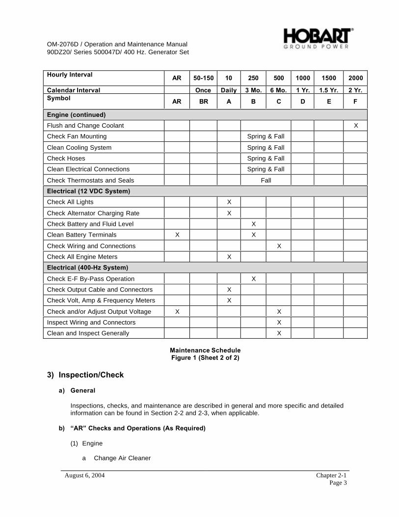
Engine (continued)
Flush and Change Coolant X
Check Fan Mounting Spring & Fall
Clean Cooling System Spring & Fall
Check Hoses Spring & Fall
Clean Electrical Connections Spring & Fall
Check Thermostats and Seals Fall
Electrical (12 VDC System)
Check All Lights X
Check Alternator Charging Rate X
Check Battery and Fluid Level X
Clean Battery Terminals X X
Check Wiring and Connections X
Check All Engine Meters X
Electrical (400-Hz System)
Check E-F By-Pass Operation X
Check Output Cable and Connectors X
Check Volt, Amp & Frequency Meters X
Check and/or Adjust Output Voltage X X
Inspect Wiring and Connectors X
Clean and Inspect Generally X
Maintenance ScheduleFigure 1 (Sheet 2 of 2)
3) Inspection/Check
a) General
Inspections, checks, and maintenance are described in general and more specific and detailedinformation can be found in Section 2-2 and 2-3, when applicable.
b) “AR” Checks and Operations (As Required)
(1) Engine
a Change Air Cleaner
OM-2076D / Operation and Maintenance Manual90DZ20/ Series 500047D/ 400 Hz. Generator Set
August 6, 2004 Chapter 2-1Page 4
A definite time schedule for changing the air cleaner cannot be established. This filter shouldnot be washed more then six times or retained for more than one year of service, which evercomes first.
b Check and tighten, as required, all coolant hose clamps, air intake hose clamps and exhaustclamps. Check all coolant hoses, air intake hoses and exhaust pipes for leaks.
(2) Electrical System (12 VDC)
a Check Battery Terminals
Anytime the compartment doors are opened for any reason, visually check battery cableconnectors and battery posts. If corrosion is observed, disconnect cables and clean batteryposts and connectors with a wire brush or special battery post-cleaning tool. Coat posts andconnectors with a light film of petroleum lubricant before reconnecting cables.
(3) Electrical (400 Hz System)
a Check the output voltage and be sure it is set for 115 VAC ± 1 V. Adjustment can be madeusing the fine adjustment located on the Voltage Regulator PC Board (REG).
c) “BR” Checks and Operations (Break-In Period, Once After 50-150 hrs.)
The following procedures are precautionary measures taken on most new engines. If a problemoccurs with any of the following issues be sure to recheck it after the next 50-150 hours.
(1) Engine
a Check for leaks and correct. This involves an overall inspection of the engine and mayrequire some maintenance if leaks are found. Refer to the engine manufacturer’s operationsmanual for assistance.
b Change all fuel filter elements. Metal shavings from the new fuel tank can clog the filter.
c Change crankcase oil. New engines often release metal shavings more frequently. Thereforethe crankcase oil must be changed as a precautionary measure.
d Change oil filter element. The oil filter should be changed with the oil.
e Check engine and generator mounts to ensure they are properly installed and they have notworked loose. (Torque is set at 122 N-m, 90 ft-lb.).
f Check coolant additive concentration. Refer to the engine manufacturer’s operations manualfor assistance.
g Steam clean the engine to free it of oil and dirt to prevent uneven engine cooling “hot spots”.The oil and dirt can also fall into the engine and fuel system when covers are removed duringrepair work.
h Inspect the water pump weep hole for indication of a steady leak. If a steady flow of coolantor oil is observed, replace the water pump with a new or rebuilt unit. Refer to the enginemanufacturer’s operations manual for assistance.

OM-2076D / Operation and Maintenance Manual90DZ20/ Series 500047D/ 400 Hz. Generator Set
August 6, 2004 Chapter 2-1Page 5
d) “A” Checks and Operations (10 Hours or Daily)
(1) Engine
a Check Crankcase Oil Level
CAUTIONDO NOT overfill. DO NOT operate the engine with oil level below the lower bar orabove the upper bar on the dipstick.
(i) Check oil level daily with oil gage dipstick.
(ii) Oil level should not be checked until 3 to 5 minutes after engine shutdown. Keep oillevel as near the upper bar as possible.
b Drain Fuel Pre-Filter Element
The life of the fuel pump and injectors can be extended if the operator drains about a cup offuel from the fuel pre-filter element to remove water and sediment before starting the engineeach day.
CAUTIONBE SURE to prime and bleed the fuel system after draining the filters, replacing filterelement, or if the fuel tank has run empty. Failure to do so can cause engine startingproblems.
(i) Provide a container for catching drained fuel.
(ii) Open the drain valve on the fuel/water filter by turning it counterclockwise.
(iii) Drain the filter until clear fuel is visible.
(iv) Tighten the drain valve.
(v) Safely dispose of drained fuel.
(vi) Purge air from fuel system if necessary.
c Check Coolant Level
Check coolant level daily or at each fuel fill interval. Investigate for cause of any coolant loss.
WARNINGCooling system is pressurized. To avoid personal injury, DO NOT remove radiatorcap when engine is hot.
d Check for Leaks and Correct
At each daily start-up, check for coolant, fuel, and oil leaks. Coolant leaks may be morenoticeable when components are cold. Observe pumps, hoses, fittings, gasket connections,etc., for signs of leakage. Correct as required.

OM-2076D / Operation and Maintenance Manual90DZ20/ Series 500047D/ 400 Hz. Generator Set
August 6, 2004 Chapter 2-1Page 6
Fuel Pre-Filter and DrainFigure 2
e Check Air Cleaner Indicator
At each daily start-up, observe the air cleaner indicator light. If this light comes ON, itindicates that the air cleaner should be changed.
f Check Exhaust System
Visually inspect muffler and exhaust pipes for rust and signs of approaching failure. Listen forany gasket or joint leaks.
WARNINGA leaking and defective exhaust system could be a fire hazard.
(2) Electrical System (12 VDC)
a Check All Lights
Check all indicating lights to be sure they will operate when they should. If any light fails tooperate, check both the lamp and its protective circuit breaker. Figure 5 lists all lamps withtheir location and part number. Figure 6 lists all circuit breakers.
b Check Alternator Charging Rate
Observe the 12 VDC ammeter each time the engine is started. A zero amperage reading orextremely high reading for any length of time indicates trouble in the alternator, regulator,battery, or interconnecting wiring.
c Check the operation of all the engine meters.
Fuel Drain

OM-2076D / Operation and Maintenance Manual90DZ20/ Series 500047D/ 400 Hz. Generator Set
August 6, 2004 Chapter 2-1Page 7
(3) Electrical (400 Hz System)
b Check Output Cables and Connector
Check the output cable plug connection for damaged insulation and contacts each time theconnector is detached from the aircraft.
b Monitoring Instruments
Check operation of voltmeter, ammeter and frequency meter each time the unit is started.
e) “B” Check and Operations (250 Hours or 3 Months)
(1) Engine
a Charge-Air-Cooler and Piping
Inspect the charge-air-cooler for dirt and debris blocking the fins. Check for cracks, holes, orother damage.
Inspect the pipes and hoses for leaks, holes, cracks, or loose connections. Tighten the hoseclamps if necessary.
b Change oil and oil filters
c Check and record oil pressure
After each oil change, check and record oil pressure at idle speed after oil has warmed toapproximately 140º F. Record oil pressure under identical conditions at each oil changeinterval. A comparison of pressure at idle speed with previous readings will give an indicationof progressive wear of oil pump, bearings, shafts, etc. Investigate any abnormal change inpressure readings.
d Change all fuel filters.
e Check Radiator Core and Hoses
Inspect the radiator core for dirt and debris blocking the fins. Clean as necessary. Check forcracks, holes, or other damage.
f Check Fuel Pump
Inspect the fuel injection pump mounting nuts for loose are damaged hardware.
(2) Electrical (12 VDC system)
NOTE: The battery furnished with this generator set is MAINTENANCE FREE.
a Battery Electrolyte Level (if applicable)
Battery electrolyte level must be maintained above top of plates. Add distilled water asrequired.

OM-2076D / Operation and Maintenance Manual90DZ20/ Series 500047D/ 400 Hz. Generator Set
August 6, 2004 Chapter 2-1Page 8
CAUTIONDO NOT overfill.
b Check Battery
If battery requires water frequently, or is low in charge, the reason for the condition must befound and corrected.
c Check battery terminals and clean, if necessary.
(3) Electrical (400 Hz System)
a Check the operation of the E-F bypass system.
f) “C” Checks and Operations (500 Hours or 6 Months)
(1) Engine
a Check Engine and Generator Mounts
CAUTIONAn unstable or loosely mounted engine can create hazardous environment and mayalso damage equipment.
(i) Engine mount bolts must be torqued to 122 N-m (90 ft-lb.).
(ii) Generator mount bolts must be torqued to 122 N-m (90 ft-lb.).
b Check Coolant Additive Concentration
The cooling system protective liquid (nitrite-, amine- and phosphate free) provides effectiveprotection against corrosion, cavitation, and freezing. See engine manufacturer’s operationmanual for ordering and mixture details.
(2) Electrical (12 VDC system)
a Wiring
Inspect all cables and leads for worn or damaged insulation.
b Connections
Inspect connectors for damaged or corroded condition.
(3) Electrical (400 Hz System)
a Protective Monitoring Circuits
Check operation of all protective monitoring circuits to make certain they will function if a faultshould occurs in the output circuit. Procedures for testing these circuits are contained in theAdjustment/Test section of this manual.

OM-2076D / Operation and Maintenance Manual90DZ20/ Series 500047D/ 400 Hz. Generator Set
August 6, 2004 Chapter 2-1Page 9
b Inspect Wiring and Connections
Check all cables, leads, and wiring for broken, worn and damaged insulation. Check allconnections for tightness.
c Clean and inspect generally
g) “D” Checks and Operations (1000 Hours or 1 Year)
(1) Engine
a Check Fan Hub and Drive Pulley
Inspect for loose bolts or worn features. Tighten bolts and replace parts if necessary. Referto the engine manufacturer’s operations and maintenance manual for assistance and themost update to date information.
b Check Hose Clamps on Air Intake Side
Be sure that all clamps are properly secured to prevent leaks and all hose are in goodcondition.
c Check Belt Condition and Tensioner
Refer to the engine manufacturer’s operations and maintenance manual for assistance andthe most update to date information.
d Check and/or Adjust Valve Clearance
Refer to the engine manufacturer’s operations and maintenance manual for assistance andthe most update to date information.
e Check Water Pump
Inspect the water pump weep hole for indication of a steady leak. If a steady flow of coolantor oil is observed, replace the water pump with a new or rebuilt unit. Refer to the enginemanufacturer’s operations manual for assistance.
h) “E” Checks and Operations (1500 Hours or 1.5 Year)
(1) Engine
a Steam Clean Engine
There are several reasons why the engine exterior should be kept clean. Dirt on the outsidewill enter fuel and oil filter cases and rocker housings when covers are removed, unless dirt isremoved first. A clean engine will run cooler and develop fewer hot-spots. Steam cleaning isone of the most satisfactory methods of cleaning and engine; however, there are someCAUTIONS to be observed:

OM-2076D / Operation and Maintenance Manual90DZ20/ Series 500047D/ 400 Hz. Generator Set
August 6, 2004 Chapter 2-1Page 10
WARNINGExercise care to avoid injury and damage to eyes and skin.
CAUTION1. If a cleaning compound is used, select one that is free from acid and will notremove paint.2. Protect (or remove) all electrical accessories, such as voltage regulator, alternator,and electrical wiring.3. Seal all openings. DO NOT use a flammable solvent.4. DO NOT use mineral spirits or solvents on a hot engine.5. Remove or protect bottom panel of unit (belly pan) to protect insulation.
b Clean Fuel System
See engine manufacturer’s operation manual for instructions.
c Check Alternator and Cranking Motor.
The alternator and cranking motor on this particular engine require no periodic lubrication.
i) “F” Checks and Operations (2000 Hours or 2 Years)
(1) Engine
a Check Vibration Damper.
Check vibration damper for looseness, wobble, chunking and streaking. Also verify the hubbolts are tightened to the engine manufacturer’s specifications.
Refer to the engine manufacturer’s operations and maintenance manual for assistance andthe most update to date information.
b Check Charge-Air-Cooler and Radiator Systems
(i) Check for damaged hoses and loose or damaged hose clamps.
(ii) Check the radiator for leaks, damage, and build up of dirt in the fins. Clean orreplace as necessary.
c Flush cooling system and change coolant.
j) Seasonal Maintenance Checks Spring/Fall (Engine)
(1) Check Fan Mounting
a Check fan to be sure it is securely mounted.
b Check for fan wobble and/or broken/cracked blades.
c Check fan hub and crankshaft pulley for secure mounting.

OM-2076D / Operation and Maintenance Manual90DZ20/ Series 500047D/ 400 Hz. Generator Set
August 6, 2004 Chapter 2-1Page 11
1
2
3
4
5
1. Water Pump2. Fan Pulley3. Vibration Damper4. Alternator5. Starter Motor
Engine AccessoriesFigure 3
(2) Check cooling system each spring and fall. Clean if necessary.
(3) Check All Hoses.
In addition to daily checks of hoses for leaks, inspect hoses thoroughly each time the coolingsystem is cleaned and serviced.
Inspect for signs of deterioration and collapse. Inspect for cracks and cuts. Inspect for cuttingand deformation caused by hose clamps. Replace hoses as required.
(4) Check thermostat and seals each fall when cooling system is serviced.
k) Lamps Circuit breakers, and Fuses
(1) Check all lamps daily
(2) Check circuit breakers and fuses as required.
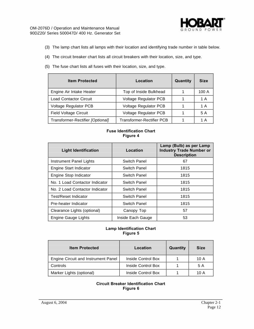
OM-2076D / Operation and Maintenance Manual90DZ20/ Series 500047D/ 400 Hz. Generator Set
August 6, 2004 Chapter 2-1Page 12
(3) The lamp chart lists all lamps with their location and identifying trade number in table below.
(4) The circuit breaker chart lists all circuit breakers with their location, size, and type.
(5) The fuse chart lists all fuses with their location, size, and type.
Item Protected Location Quantity Size
Engine Air Intake Heater Top of Inside Bulkhead 1 100 A
Load Contactor Circuit Voltage Regulator PCB 1 1 A
Voltage Regulator PCB Voltage Regulator PCB 1 1 A
Field Voltage Circuit Voltage Regulator PCB 1 5 A
Transformer-Rectifier [Optional] Transformer-Rectifier PCB 1 1 A
Fuse Identification ChartFigure 4
Light Identification LocationLamp (Bulb) as per LampIndustry Trade Number or
Description
Instrument Panel Lights Switch Panel 67
Engine Start Indicator Switch Panel 1815
Engine Stop Indicator Switch Panel 1815
No. 1 Load Contactor Indicator Switch Panel 1815
No. 2 Load Contactor Indicator Switch Panel 1815
Test/Reset Indicator Switch Panel 1815
Pre-heater Indicator Switch Panel 1815
Clearance Lights (optional) Canopy Top 57
Engine Gauge Lights Inside Each Gauge 53
Lamp Identification ChartFigure 5
Item Protected Location Quantity Size
Engine Circuit and Instrument Panel Inside Control Box 1 10 A
Controls Inside Control Box 1 5 A
Marker Lights (optional) Inside Control Box 1 10 A
Circuit Breaker Identification ChartFigure 6

OM-2076D / Operation and Maintenance Manual90DZ20/ Series 500047D/ 400 Hz. Generator Set
August 6, 2004 Chapter 2-2Page 1
Section 2 Maintenance Procedures
1) General
A suggested maintenance schedule was provided in Section 1 of this Servicing Chapter. Each step of theschedule was also covered in general in Section 1. This Section covers maintenance in more detail,where necessary.
WARNINGSTOP operations at once if a serious or possibly dangerous fault is discovered.
2) Lubrication
a) General
Proper lubrication is one of the most important steps in good maintenance procedure. Properlubrication means the use of correct lubricants and adherence to a proper time schedule. Lubricationpoints, frequency of lubrication, and recommended lubricants are indicated in Figures 1 and 2.
b) AC Generator
The 400 Hz generator requires NO lubrication.
c) Generator Controls
Generator controls and instruments require no periodic lubrication. A few drops of oil may be requiredon door hinges occasionally to insure free and quiet operation.
d) Engine
Although the engine and its accessories require no more attention than any other similar installation,they still inherently require a major portion of the generator set lubrication and maintenance.Recommendations regarding engine lubrication have been taken from the engine manufacturer’s“Operation and Maintenance Manual” and incorporated here to make them more readily available tooperators and maintenance personnel.
(1) Lubrication schedule
Time schedules indicated on the Lubrication Chart, Figure 1, are approximate. They are based onaverage operating conditions. It may be necessary to lubricate more frequently under severeoperating conditions such as: low engine temperatures, high oil temperatures, or intermittentoperation. However, time intervals should not exceed those indicated in the chart without carefulevaluation.
OM-2076D / Operation and Maintenance Manual90DZ20/ Series 500047D/ 400 Hz. Generator Set
August 6, 2004 Chapter 2-2Page 2
(2) Oil specification
Engine lubricating oil, recommended by the engine manufacturer, is identified by an API(American Petroleum Institute) classification designation. The manufacturer does not recommendany specific brand of lubricating oil.
The use of quality lubricating oil, combined with a appropriate lubricating oil drain and filterchange intervals, are important factors in extending engine life.
Oil recommended for the diesel engines in this application is API Class CCMC.
Lubricating oil is discussed in detail in the engine manufacturer’s operation manual.
(3) Oil viscosity
A temperature and oil viscosity index chart is shown below. For operation at temperaturesconsistently below -13ºF (-25ºC), refer to the engine manufacturer’s operation manual.
(4) Changing engine oil
Oil should be changed once after the first 50 - 150 hrs. of use, then every 500 hrs of engineoperation thereafter. The generator set is equipped with an hour meter to record actual engineoperating time. The ideal time to change engine oil is soon after a power delivery run, when theengine is at operating temperature.
Change the oil filter element each time the oil is changed.
NOTE: If lubricating oil is drained immediately after the unit has been run for some time, most of thesediment will be in suspension and will drain readily.
CAUTIONHigh ash oils may produce harmful deposits on valves that can cause valve burning.
CAUTIONDo not use solvents as flushing oils in running engines.
Change oil as follows:
a Provide an open container for catching the old oil below the oil drain plug. Container capacitymust be greater than 30 quarts (28.4 liters).
b The oil drain tube can be attained though a hole in the access panel underneath thegenerator set.
c Open drain plug located in oil pan.

OM-2076D / Operation and Maintenance Manual90DZ20/ Series 500047D/ 400 Hz. Generator Set
August 6, 2004 Chapter 2-2Page 3
Item Maintenance Required
Lube OilCheck oil level daily or after every 10 hours of use. Change oil and the oil filterafter the first 50 to 150 hours of use, then at 250 hour or 3 month intervalsthereafter. Use oil specification API CF-4, HT/HS Viscosity 3.7cP minimum.
Capacity 22 quarts (21 liters)
Oil Filter Replacement Oil Filter Replacement Hobart Ground Power No. 286897-013Oil Filter Replacement Engine Manufacturer No. 117-4421
VISCOSITY AMBIENT TEMPERATURE CONDITIONS
Lube Oil ViscosityRequired as perAmbient Temperatures
SAE 15W40 (Preferred)SAE 10W30SAE 5W30SAE 0W30
0ºF (-18ºC) and above for most climates-10ºF to +50ºF (-23ºC to +10ºC) Winter conditions-20ºF to +50ºF (-29ºC to +10ºC) Artic Conditions-20ºF and below to +50ºF (-29ºC and Below to +10ºC)
Synthetic OilsSee the engine manufacturer’s operations manual for usable synthetic oils andinstructions.
Fuel Pre-filter Drain Filter Daily. Change filter element every 250 hours or 3 months of use.
CoolantCheck coolant level daily. Service and maintain coolant system according toSection 2-2, paragraph 6. Engine coolant capacity (system): 40 quarts (37.8liters)
Coolant hoses andconnections
Check coolant hoses and connections daily for leaks.
Air CleanerChange air cleaner filter as required when air cleaner indicator (on engine controlpanel) shows that it should be changed.
Fan Belt Check fan belt condition and tension every 500 hours or 6 months of use.
AC Generator AC generator bearings are sealed and require no periodic lubrication.
Alternator Alternator bearings are sealed and require no periodic lubrication.
Starter Starter motor bearings are sealed and require no periodic lubrication.
Water Pump The water pump is packed at assembly and requires no periodic lubrication.
Fan Hub The fan hub is lubricated at assembly and requires no periodic lubrication.
Lubrication and Maintenance ChartFigure 1
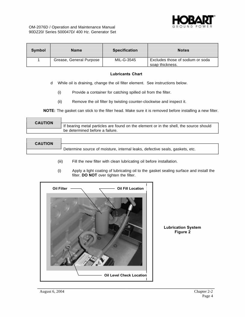
OM-2076D / Operation and Maintenance Manual90DZ20/ Series 500047D/ 400 Hz. Generator Set
August 6, 2004 Chapter 2-2Page 4
Symbol Name Specification Notes
1 Grease, General Purpose MIL-G-3545 Excludes those of sodium or sodasoap thickness.
Lubricants Chart
d While oil is draining, change the oil filter element. See instructions below.
(i) Provide a container for catching spilled oil from the filter.
(ii) Remove the oil filter by twisting counter-clockwise and inspect it.
NOTE: The gasket can stick to the filter head. Make sure it is removed before installing a new filter.
CAUTIONIf bearing metal particles are found on the element or in the shell, the source shouldbe determined before a failure.
CAUTIONDetermine source of moisture, internal leaks, defective seals, gaskets, etc.
(iii) Fill the new filter with clean lubricating oil before installation.
(i) Apply a light coating of lubricating oil to the gasket sealing surface and install thefilter. DO NOT over tighten the filter.
Oil Fill Location
Oil Level Check Location
Oil Filter
Lubrication SystemFigure 2

OM-2076D / Operation and Maintenance Manual90DZ20/ Series 500047D/ 400 Hz. Generator Set
August 6, 2004 Chapter 2-2Page 5
e Clean the drain plug and install when engine oil has completely drained. Torque the drainplug to 50 foot-pound (68 Nm).
f Use the oil refill tube to refill the crankcase with new, clean oil that meets enginemanufacturer’s recommendations.
NOTE: Using a funnel to fill the oil crankcase will help prevent spills.
Lubricating oil capacity (w/ filter) 22 quarts (21 liters)Coolant capacity system 40 quarts (37.8 liters)
CAUTION1. Always use clean containers, funnels, etc.2. Don’t forget to close the drain plug valve, and install the new oil, before starting theengine.
g Start engine and check oil pressure at once. Allow engine to idle for 5 minutes, check forleaks, than stop the engine.
h After the engine has been stopped for about 5 minutes, recheck the oil level. Add oil, ifrequired, to bring the level up to the high bar on the oil dipstick.
e) Engine Accessories Lubrication
(1) Alternator
Most alternators contain sealed bearings and require no periodic lubrication, however, CHECK tomake certain there are no lubrication points on your particular alternator.
(2) Starter
Most starting motors are lubricated at assembly and should be re-lubricated only when the starteris removed and disassembled, however, INSPECT the starter to make certain it has nolubrication points.
(3) Water Pump
The water pump is packed at assembly and requires no periodic lubrication. Replace pump ifsigns of lubricant leakage are found.
(4) Fan Pulley
The fan hub is also lubricated at assembly and requires no periodic lubrication. Replace hub iflubricant is leaking.
3) Servicing the Air Cleaner
This air cleaner is a disposable type which, when dirty may be discarded. A definite time schedule forcleaning or changing the air cleaner cannot be determined because of varying operating conditions. Thisair cleaner filter can be removed from the air cleaner housing and replaced by unfastening the three metalclamps on the end of the air cleaner housing. It may be inspected either at prescribed service intervals orat any time deemed necessary.
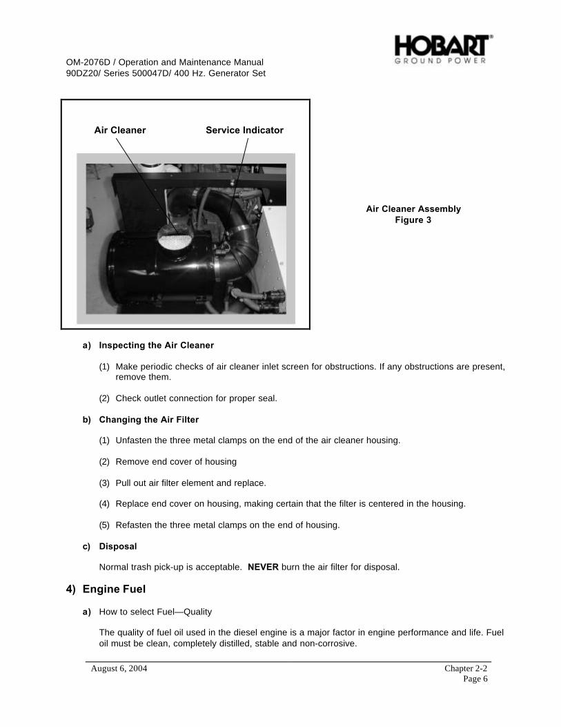
OM-2076D / Operation and Maintenance Manual90DZ20/ Series 500047D/ 400 Hz. Generator Set
August 6, 2004 Chapter 2-2Page 6
Service IndicatorAir Cleaner
Air Cleaner AssemblyFigure 3
a) Inspecting the Air Cleaner
(1) Make periodic checks of air cleaner inlet screen for obstructions. If any obstructions are present,remove them.
(2) Check outlet connection for proper seal.
b) Changing the Air Filter
(1) Unfasten the three metal clamps on the end of the air cleaner housing.
(2) Remove end cover of housing
(3) Pull out air filter element and replace.
(4) Replace end cover on housing, making certain that the filter is centered in the housing.
(5) Refasten the three metal clamps on the end of housing.
c) Disposal
Normal trash pick-up is acceptable. NEVER burn the air filter for disposal.
4) Engine Fuel
a) How to select Fuel—Quality
The quality of fuel oil used in the diesel engine is a major factor in engine performance and life. Fueloil must be clean, completely distilled, stable and non-corrosive.

OM-2076D / Operation and Maintenance Manual90DZ20/ Series 500047D/ 400 Hz. Generator Set
August 6, 2004 Chapter 2-2Page 7
CAUTIONDue to the precise tolerances of diesel injection systems, it is extremely important thatthe fuel be kept clean and free of dirt or water. Dirt or water in the system can causesevere damage to both the injection pump and the injection nozzles.
Use commercially available diesel fuel with less than 0.5% sulfur content. If the sulfur content ishigher than 0.5%, oil change intervals should be reduced (See engine manufacturer’s operationmanual).
In general, fuels meeting the properties of ASTM designation D 975 (grades 1-D and 2-D) haveprovided satisfactory performance. For more information regarding the selection of fuel to use, referto publication “Engine Requirements—Lubricating Oil, Fuel, and Filters” available from authorizedengine manufacturer’s service outlets.
b) Cold Weather Operation
In cold weather, diesel fuel will form wax crystals, which can restrict flow and clog filters. Fuel oilsuppliers approach this problem several ways. Some provide a specially refined product, whileothers may use flow-improving additives or winter blends. Winter blended fuel will likely containkerosene or 1-D fuel, which provide good cloud point temperatures, but result in a lighter fuel with alower heat content. These fuels may be used, but they may result in reduced engine power and/orfuel mileage.
In most cases, adequate resistance to cold can be obtained by adding an additive. For furtherassistance contact the nearest engine manufacturer’s service representative.
5) Engine Fuel System
The fuel system consists of five primary components: Fuel tank, Fuel Water Separator (Pre-Filter), FuelLift Pump, Fuel Filter, and the Fuel Return Line. The following are maintenance procedures for each ofthese items.
a) Fuel Tank
Be sure that no foreign objects are permitted in the fuel tank. The fuel tank must be removed andflushed out if objects are found in the Fuel Water Separator
b) Fuel Water Separator
Hobart Ground Power has mounted a fuel water separator on the inner wall of the canopy. Itsfunction is to remove foreign material and extract water from the fuel before it enters the fuel liftpump. Daily draining of the filter water separator bowl is required.
OM-2076D / Operation and Maintenance Manual90DZ20/ Series 500047D/ 400 Hz. Generator Set
August 6, 2004 Chapter 2-2Page 8
(1) Draining the fuel water separator bowl.
a Open drain valve
b Drain accumulated water and contaminants.
c Close drain valve.
(2) Priming fuel water separator (when applicable).
a Loosen the vent plug.
b Pump until fuel purges at the vent plug.
c Close the vent plug, start the engine and check for leaks,
d Correct as necessary with the engine off.
(3) Changing the fuel water separator element (when applicable).
a The filter element replacement part number.
• Hobart Part No. 286897-027• Deutz Part No. 1340130
b Drain off some fuel by loosening the vent plug and opening the drain valve.
c Spin the element and bowl off together. Remove the bowl and clean the O-ring gland.
d Apply a coating of clean fuel or motor oil to the new O-ring and element seal. Spin the bowlonto the new element and the spin them both onto the filter head snugly by hand only. DONOT USE TOOLS TO TIGHTEN!
e With the vent plug still loosened, pump knob until fuel purges at the vent plug. Close the ventplug, start the engine and check for leaks, correct as necessary with the engine off.
NOTE: The priming pump in the filter assembly is in tended for priming fuel into the Racor filter onlyand not the entire fuel system.
c) Fuel Pump
The fuel pump supplies pressure to the fuel system so the diesel fuel can circulate freely. Aconsistent check of the fuel pressure is necessary. Loss in fuel pressure in the fuel line may indicatea faulty fuel pump.
d) Engine Fuel Filter
The forth item in the fuel line system is the factory installed fuel filter. The filter function is to removeforeign material from the fuel under pressure before it enters the engine. The filament element is athrowaway type in which the case and element are made as one disposable part.
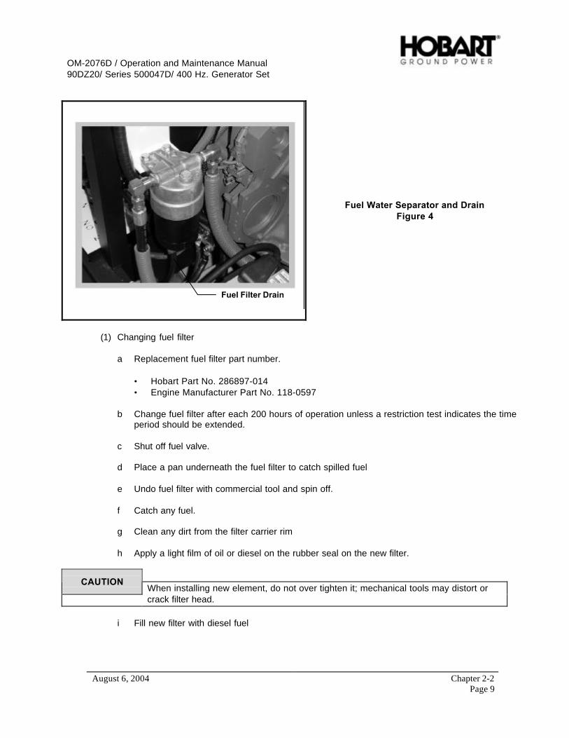
OM-2076D / Operation and Maintenance Manual90DZ20/ Series 500047D/ 400 Hz. Generator Set
August 6, 2004 Chapter 2-2Page 9
Fuel Filter Drain
Fuel Water Separator and DrainFigure 4
(1) Changing fuel filter
a Replacement fuel filter part number.
• Hobart Part No. 286897-014• Engine Manufacturer Part No. 118-0597
b Change fuel filter after each 200 hours of operation unless a restriction test indicates the timeperiod should be extended.
c Shut off fuel valve.
d Place a pan underneath the fuel filter to catch spilled fuel
e Undo fuel filter with commercial tool and spin off.
f Catch any fuel.
g Clean any dirt from the filter carrier rim
h Apply a light film of oil or diesel on the rubber seal on the new filter.
CAUTIONWhen installing new element, do not over tighten it; mechanical tools may distort orcrack filter head.
i Fill new filter with diesel fuel
OM-2076D / Operation and Maintenance Manual90DZ20/ Series 500047D/ 400 Hz. Generator Set
August 6, 2004 Chapter 2-2Page 10
j Screw in the new fuel filter “snug”. Check that the cartridge is seated correctly against thegasket and tighten with a final half turn.
k Open fuel valve.
e) Fuel Return
The fuel return is a fuel line (tube) that takes unused fuel from the engine, and delivers it to the fueltank. No maintenance is required.
f) Priming Fuel System (when applicable)
If this generator set has been run out of fuel, the fuel system must be manually primed with diesel fuelup to the fuel water separator before the generator set can be started again. See Paragraph 5, b, (2)for instructions for priming the fuel water separator system. Once the fuel has reached the fuel waterseparator, close all open valves (i.e. filter vent plug) and cranked the engine until the fuel reaches theinjectors and the engine starts.
CAUTIONMake sure that all rags, or absorbent sheets, are clear of moving engine parts andcannot be drawn in to the radiator fan.
CAUTIONDo not crank the engine for more then 15 seconds continuously. Allow the starter tocool for 15 seconds between attempts.
6) Engine Cooling System
a) General
Cooling system service requires more than maintaining the proper coolant level in the radiator andprotecting the system against freezing. Water should by clean and free of any corrosive chemicalssuch as chloride, sulfate, and acids. It should be kept slightly alkaline with a pH value in the range of8.0 to 9.5. Any water which is suitable for drinking can be used in the engine when properly treatedas described in Engine manufacturer’s operation manual. The engine manufacturer’s representativeshould be consulted regarding the selection of satisfactory brand, permanent-type antifreeze for usein the cooling system.
b) Radiator Cap
(1) General
A pressure relief valve is built into the radiator cap. It is designed to open at a pressure ofapproximately 10 psi (68.9 Kpa).
WARNINGWhen removing cap from a very hot radiator, do not turn cap past safety stop until thepressure or steam has escaped.
OM-2076D / Operation and Maintenance Manual90DZ20/ Series 500047D/ 400 Hz. Generator Set
August 6, 2004 Chapter 2-2Page 11
(2) Removal
To remove, turn the cap to the left (counterclockwise) to the safety stop. When all pressure isreleased, press down on the cap and continue to turn until the cap is free to be removed.
CAUTIONAllow engine to cool before adding coolant.
CAUTIONDo not attempt to repair the valve in a radiator cap in case of failure. Replace with anew cap.
(3) Installation
When installing the cap, be sure it is turned clockwise as far as it will go so that the pressureretaining valve will be functional.
c) Coolant
The preparation and maintenance of the coolant solution is important to engine life and is completelycovered in the engine manufacturer’s operation manual. For information regarding coolantspecifications, testing equipment, antifreeze, etc., refer to engine manufacturer’s operation manualthat accompanies the Hobart manual or consult the local engine manufacturer’s representative.
CAUTIONNever use soluble oil in the cooling system.
(1) General
A permanent type antifreeze is recommended for use in the cooling system.
CAUTION1. DO NOT use methanol or alcohol as antifreeze.
2. DO NOT mix brands or type of antifreeze. A solution containing two or moretypes of antifreeze is impossible to test accurately.
(2) Selecting antifreeze
a Select a permanent type antifreeze known to be satisfactory for use with chromate corrosionresistor.
b When it is not known if the antifreeze is satisfactory for use with chromate resistor, check withlocal engine manufacturer’s representative for a list of compatible antifreezes.
(3) Checking antifreeze solution
Check the solution with a reliable tester when in doubt about antifreeze protection.
OM-2076D / Operation and Maintenance Manual90DZ20/ Series 500047D/ 400 Hz. Generator Set
August 6, 2004 Chapter 2-2Page 12
d) Draining the Cooling System
To completely empty the cooling system requires draining the engine block and the radiatorassembly. Both of the drain valves (radiator and block drain), CAN BE opened/closed at the sametime but they DO NOT need to be.
To drain the cooling system, proceed as follows:
(1) Remove radiator cap.
(2) Place a drain pan with at least a 40 quart (28.4 liters) capacity under radiator to catch coolant.
(3) Place the radiator drain hose that comes off the two radiator drain valves, into the drain pans.
(4) Open the radiator drain valves.
(5) Allow the system to drain completely.
NOTE: Be sure the drain valves do not clog during draining.
(6) When the system is completely drained, close the drain valves and replace engine drain plug.
e) Flushing the Cooling System
Flushing the cooling system should be a yearly maintenance procedure. By flushing the system,clean water is forced through the engine block to remove expired coolant and other contaminants.
f) Cleaning the Radiator Core
Blow out accumulated dirt from the radiator core air passages, using water. Engine overheating isoften caused by bent or clogged radiator fins. When straightening bent fins, be careful not to damagethe tubes or to break the bond between fins and tubes.
NOTE: Direct the water in a reverse direction to normal air flow. Normal flow on this installation isfrom the engine compartment out ward.
g) Filling the Cooling System
The preparation and monitoring of coolant in liquid-cooled engines is especially important becausecorrosion, cavitation, and freezing can lead to engine damage. For coolant system protection detailssee the engine manufacturer’s operations manual.
(1) Install coolant
a Remove radiator cap. Be sure that both radiator drain valves are closed.
b Pour coolant into radiator very slowly until it reaches the bottom of fill neck. Allow time fortrapped air to escape from the system then continue filling until the coolant level remains atthe bottom of the fill neck.
c Start the engine and bring up to rated speed and allow the thermostat to open. Add coolantas trapped air escapes from the system and the coolant level falls.
OM-2076D / Operation and Maintenance Manual90DZ20/ Series 500047D/ 400 Hz. Generator Set
August 6, 2004 Chapter 2-2Page 13
d Continue to check coolant level until all trapped air escapes. Add coolant if needed to fill tothe bottom of fill neck. Install radiator cap.
(2) Inspection/Check
a Check system for evidence of leaks.
b Inspect all hoses. Install new hoses as necessary. Tighten hose clamps as required.
c Check the condition of fan and water pump belts. Replace belts if necessary.
NOTE: It is good practice to attach a card, indicating the cooling system contents and date serviced,to the radiator filler neck.
h) Thermostat
The thermostat should be checked each fall, or as required. Refer to engine manufacturer’soperations manual for recommended instructions.
7) Generator Maintenance
The 400 Hz generator requires no maintenance or service other than periodic cleaning. The unit isbrushless and has bearings that are permanently lubricated and sealed.
a) Cleaning
The generator may be cleaned by careful use of compressed air and/or a good, SAFE commercialcleaner. Steam cleaning of the generator is not recommended because the use of steam and harshchemical compounds may result in damage to insulation and other generator components.
CAUTIONDo not use a flammable solvent. Be sure the unit is completely dry before operating.
b) Adjustment
The generator itself requires no adjustment. Adjustment procedures for generator controls arecovered in Section 2-3.
8) Drive Belt
a) General
The engine cooling fan, alternator, and water pumps are driven by one serpentine belt, which must bereplaced if worn or damaged.
b) Preparation for Belt Check and Adjustment
All driven assemblies must be securely mounted in operating position before checking belt tension.
OM-2076D / Operation and Maintenance Manual90DZ20/ Series 500047D/ 400 Hz. Generator Set
August 6, 2004 Chapter 2-2Page 14
c) Checking Belt Tension
CAUTIONChecking the tension and changing the serpentine belt should only be performed withthe engine off.
Check belt tension every 500 hours, or once a half-year, whichever comes first. A belt that is too tightis destructive to bearings of the driven part. A loose belt will slip and cause inefficient operation of thepart being driven as well as wear to the belt.
CAUTIONInspect and replace the belt if it has unacceptable cracks, is frayed, or has pieces ofmaterial missing.
Belt tension may be checked by hand. To do so, manually depress the belt with an index finger todetermine the amount of belt deflection obtained. When a force is applied at a point halfway betweenpulleys on the longest span of a belt, there should be no more than 1/2 inch of deflection attained.
Refer to the engine manufacturer’s operation manual for checking belt tension and changing wornbelts.
OM-2076D / Operation and Maintenance Manual90DZ20/ Series 500047D/ 400 Hz. Generator Set
August 6, 2004 Chapter 2-3Page 1
Section 3 Adjustment/Test
1) General
These adjustments and test procedures are applicable to testing and adjusting the generator set aftermajor repair, major parts replacements, or overhaul.
IMPORTANTIn order to perform most of the following test, a load bank with an EF interlock circuitis required. But if no EF interlock is available on a load bank, see special procedurein the EF Bypass section for testing the EF circuit.
2) Testing the 400 Hz. Generator Set
a) Pre-operational Test Procedures
(1) Connect cables from the generator output terminals to a load bank. Use cables of the same sizeand length as those to be used in service. Be sure the generator output N cable is grounded.
(2) Check engine oil level. Oil should be at high bar on the dipstick.
(3) Check radiator coolant level (See 2-2, Paragraph 6)
(4) Check tension of drive belt (See 2-2, Paragraph 8).
(5) Inspect for oil, fuel and coolant leaks.
(6) If the setting of the output voltage coarse adjustment potentiometer (Figure 8) on the voltageregulator has been disturbed, set it at center position (halfway between full clockwise position andfull counterclockwise position).
(7) Check control panel lights circuit breaker (Figure 3) by pressing panel “LAMPS” push buttonswitch (Figure 2). If panel lights operate, the circuit breaker, switch, and lamps are good.
(8) Check fault indication lights by pressing “TEST/RESET” push button switch (Figure 2). If faultcode display lights up, the control circuit breaker (Figure 3) is good.
(9) Make a general inspection of all wiring, and terminals. Inspect the equipment to be certain nodamage will result from starting the engine.
b) Operational Test Procedures
(1) Start the engine in accordance with instructions in Section 1-3, Paragraph 2.
(2) Check operation of engine instruments: ammeter, coolant temperature indicator, oil pressuregage and hour meter (all shown in Figure 1).
(3) Check engine idle speed. Should be 1000 +/- 25 RPM.
NOTE: A stroboscope may be required for this check.
(4) Again check for oil, fuel, and coolant leaks and correct any leaking condition.
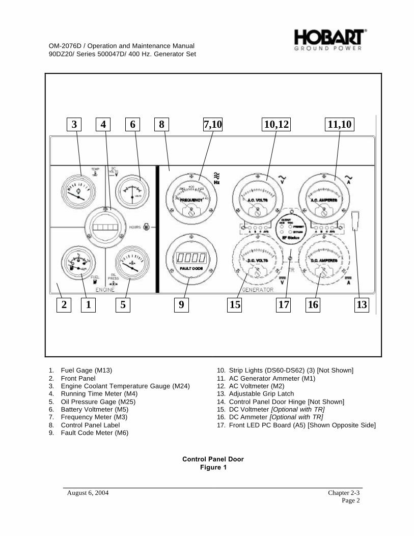
OM-2076D / Operation and Maintenance Manual90DZ20/ Series 500047D/ 400 Hz. Generator Set
August 6, 2004 Chapter 2-3Page 2
12
3 4
5
6 8 7,10 11,1010,12
139 15 1617
1. Fuel Gage (M13)2. Front Panel3. Engine Coolant Temperature Gauge (M24)4. Running Time Meter (M4)5. Oil Pressure Gage (M25)6. Battery Voltmeter (M5)7. Frequency Meter (M3)8. Control Panel Label9. Fault Code Meter (M6)
10. Strip Lights (DS60-DS62) (3) [Not Shown]11. AC Generator Ammeter (M1)12. AC Voltmeter (M2)13. Adjustable Grip Latch14. Control Panel Door Hinge [Not Shown]15. DC Voltmeter [Optional with TR]16. DC Ammeter [Optional with TR]17. Front LED PC Board (A5) [Shown Opposite Side]
Control Panel DoorFigure 1

OM-2076D / Operation and Maintenance Manual90DZ20/ Series 500047D/ 400 Hz. Generator Set
August 6, 2004 Chapter 2-3Page 3
1245678910 3
1. Meter Selector Switch (S3)2. Test/Reset Switch (S77)3. Engine Stop Switch (S76)4. DC Starting Current Switch (S431) [Optional with TR]5. DC Output Contactor Switch (S430) [Optional with TR]
6. AC Output No. 2 Contactor Switch (S275)7. AC Output No. 1 Contactor Switch (S75)8. Engine Start Switch (S24)9. Air Intake Heater Switch (S79)10. Panel Light Switch (S74)
Control Push-Button Switch PanelFigure 2

OM-2076D / Operation and Maintenance Manual90DZ20/ Series 500047D/ 400 Hz. Generator Set
August 6, 2004 Chapter 2-3Page 4
2
3
1
4
5
6
711 9 810
1. Control Box Wrapper2. Engine Specific PC Board [ESB] (A1)3. Engine Interface PC Board [EIB] (A2)4. Digital Control PC Board [CTL] (A3)5. Voltage Regulator PC Board [REG] (A4)6. Transformer-Rectifier PC Board [TRB] (A404) {Optional}
7. +5, -12 VDC Power Supply (PS1)8. Circuit Breaker Support Bracket9. Marker Lights Circuit Breaker, 10 A (CB1)10. Engine Circuit Breaker, 10 A (CB4)11. Controls Circuit Breaker, 5 A (CB7)
Control Box Interior ComponentsFigure 3
OM-2076D / Operation and Maintenance Manual90DZ20/ Series 500047D/ 400 Hz. Generator Set
August 6, 2004 Chapter 2-3Page 5
(5) Position switches and controls for automatic voltage regulation and power delivery as follows:
a Place regulated-diagnostic switch (Figure 8) in “REGULATED” position.
b Place EF Bypass switches (Figure 4) in “BYPASS / OFF” position.
c If the output voltage coarse adjustment potentiometer (Figure 8) on the voltage regulator hasbeen disturbed, place the knob at mid-range position.
(6) Bring the engine up to rated speed, which also energize the generator, by pressing the “ENGINESTART” push button switch (Figure 2) a second time. If the engine comes up to rated speed anda 115 V voltage value appears on the voltmeter (Figure 1), the engine EMR and excitation circuitsare functioning.
(7) After generator overhaul or repair, the Regulated/Diagnostic switch (Figure 8) must be placed inthe “DIAGNOSTIC” position for 3 to 5 seconds to re-magnetize the exciter. Then return the switchto the “REGULATED“ position after voltage has built-up.
(8) Observe frequency meter (Figure 1). If engine speed is properly set, frequency should read 400Hz.
(9) Observe voltmeter (Figure 1). Use output fine voltage coarse adjustment potentiometer (Figure 8)to adjust voltage to 115 V AC.
(10) Check adjustable voltage range.
a Observe voltmeter (Figure 1) and turn output voltage coarse adjustment potentiometer(Figure 8) to full clockwise position. Maximum voltage should be 134 volts or higher.
NOTE: If voltage should decrease when regulator potentiometer is turned clockwise, it indicates thatinternal wiring in the voltage regulator is incorrect. Replace complete voltage regulator assembly.
b Observe voltmeter and turn regulator potentiometer knob to full counterclockwise position.The minimum voltage should be 95 volts or lower.
(11) Position load bank switches, etc., to apply a light load to the generator.
c) Testing the No. 1 Output Circuit
(1) Place EF Bypass switch (Figure 4) in “BYPASS / OFF” position turn the EF signal “ON” on theload bank. Then press the yellow No. 1 load contactor push button switch (Figure 2) to closecontactor, which is indicated when its internal indicating light glows.
(2) Place EF switch on the load bank in the off position. The No. 1 load contactor should openimmediately, and the indicating light within the push button switch should go off. The fault codedisplay should also read “EF 1”, indicating an EF warning. This is because the interlock circuit ofthe control PC board is not receiving 28.5 VDC signal from an outside source. It indicates thatthe No. 1 interlock circuit is OPEN, as it should be when the interlock circuit is not receiving a 28VDC signal. Reset the fault by pressing the “TEST/RESET ” push button (Figure 2).
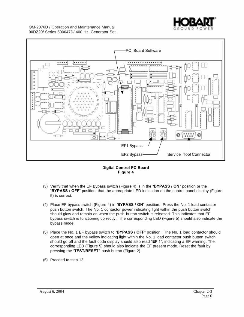
OM-2076D / Operation and Maintenance Manual90DZ20/ Series 500047D/ 400 Hz. Generator Set
August 6, 2004 Chapter 2-3Page 6
EF1 Bypass
EF2 Bypass
PC Board Software
Service Tool Connector
Digital Control PC BoardFigure 4
(3) Verify that when the EF Bypass switch (Figure 4) is in the “BYPASS / ON” position or the“BYPASS / OFF” position, that the appropriate LED indication on the control panel display (Figure5) is correct.
(4) Place EF bypass switch (Figure 4) in “BYPASS / ON” position. Press the No. 1 load contactorpush button switch. The No. 1 contactor power indicating light within the push button switchshould glow and remain on when the push button switch is released. This indicates that EFbypass switch is functioning correctly. The corresponding LED (Figure 5) should also indicate thebypass mode.
(5) Place the No. 1 EF bypass switch to “BYPASS / OFF” position. The No. 1 load contactor shouldopen at once and the yellow indicating light within the No. 1 load contactor push button switchshould go off and the fault code display should also read “EF 1”, indicating a EF warning. Thecorresponding LED (Figure 5) should also indicate the EF present mode. Reset the fault bypressing the “TEST/RESET ” push button (Figure 2).
(6) Proceed to step 12.

OM-2076D / Operation and Maintenance Manual90DZ20/ Series 500047D/ 400 Hz. Generator Set
August 6, 2004 Chapter 2-3Page 7
(Steps 8 - 11 are only required if EF interlock system is not available on a load bank.)
(7) Connect a source of 24 V-DC power (two twelve-volt batteries connected in series) to terminalsN, F (or E) at the output terminal panel. Connection polarity is important. Connect plus (+) toterminals E or F, and minus (-) to terminal N.
(8) Verify that when the EF Bypass switch (Figure 4) is in the “BYPASS / ON” position or the“BYPASS / OFF” position, that the appropriate LED indication on the control panel display (Figure5) is correct during the following steps 9 and 10.
(9) Place the No. 1 EF bypass switch to “BYPASS / OFF” position. Press the No. 1 contactoroperating push button switch (Figure 2). The No. 1 contactor power on indicating light, within thepush button switch, should glow and remain on when the push button switch is released. Thisindicates that the load contactor is closed and the plug interlock circuit is functioning properly.
(10) Disconnect the 24 V-DC power source and the No. 1 load contactor should open immediately,and the indicating light within the push button switch should go OFF. The fault code displayshould also read “EF 1”, indicating an EF warning. This is because the interlock circuit of thecontrol PC board is not receiving 28.5 VDC signal from an outside source. It indicates that theNo. 1 interlock circuit is OPEN, as it should be when the interlock circuit is not receiving a 28 VDCsignal. Reset the fault by pressing the “TEST/RESET” push button (Figure 2).
EF Bypass IndicationFigure 5
(11) In EF bypass mode, apply 1/3 to 1/2 load at the load bank and allow the unit to run for 15 to 30minutes. Observe operation of all monitoring instruments.
(12) Increase load at the load bank to full load.
(13) Check operation of the engine EMR by observing the frequency meter (Figure 1) when generatoris switched from no load to full load, and vice versa. Use the No. 1 contactor control push buttonswitch to apply and remove load several times. Steady-state frequency droop should be no morethan 1 Hz.
(14) Follow instructions in Paragraph 3 to set voltage regulator line drop compensation for the lengthand size of cable being used.
EF Bypass Indication

OM-2076D / Operation and Maintenance Manual90DZ20/ Series 500047D/ 400 Hz. Generator Set
August 6, 2004 Chapter 2-3Page 8
(15) Check voltage regulator, at intervals, from no load to full load. Observe and note voltage atvarious loads. Steady-state voltages should vary no more than +/- 1% from normal outputvoltage.
(16) Operate the No. 1 output circuit of the unit no less than 10 minutes under full load. The overloadprotection MUST NOT trip.
(17) Operate the No. 1 output circuit of the unit at 125% load (325 amperes) for 5 minutes immediatelyfollowing the full load run. The overload device MUST trip within 5 minutes, and the fault codedisplay should read “70.18” indicating an overload condition in “OUTPUT NO 1” (Reference faultchart in Section 2-4).
(18) Reset the fault by pressing “TEST/RESET ” push button (Figure 2).
d) Testing the No. 2 output circuit
(1) Repeat steps (1) through (18) in the previous section “Testing the No. 1 Output Circuit” fortesting the No. 2 output circuit.
e) Testing and checking meters, switches, protective monitoring circuits, and fault code display
(1) Check accuracy of AC voltmeter
a Open door of control box and connect a master voltmeter of known accuracy to terminals ofthe AC voltmeter (Figure 1).
b Compare the unit’s voltmeter reading with master meter. Error must not exceed 2% of fullscale.
(2) Check accuracy of AC ammeter
a Connect a master ammeter of known accuracy to the AC ammeter (Figure 1).
b Compare the unit’s ammeter reading with master meter under various loads. Error must notexceed 4% of full scale.
(3) Check operation of the “METER SELECT” switch (Figure 2).
a In any LINE-TO-NEUTRAL position, the voltmeter reading should be 115 volts when the LEDunder the voltmeter indicates one of the 3 phase being check (Figure 5).
b In any LINE-TO-LINE position, voltmeter reading should be 200 volts when the LED underthe voltmeter indicates two of the phases being checked (Figure 5).
(4) Check accuracy of frequency meter
a Connect a master frequency meter of known accuracy to the terminals of the frequency meter(Figure 1).
b Compare meter readings. Error must not exceed 1% of full scale.
OM-2076D / Operation and Maintenance Manual90DZ20/ Series 500047D/ 400 Hz. Generator Set
August 6, 2004 Chapter 2-3Page 9
NOTE: Make all protective system tests with the unit operating under a load for the following steps.Reference Chapter 2, Section 4, for all fault codes.
(5) Check operation of over-voltage circuit and fault code display.
a With the unit running at a normal load, adjust the coarse adjustment potentiometer (Figure 8)on the voltage regulator clockwise to increase voltage until the over-voltage sensing circuitactuates the protective monitor. After the protective monitor is activated, the load contactorwill open and the fault code display will display fault “70.16”. At 125 volts, the circuit will tripafter a 1-second time delay. At higher values of voltage, time delays for over voltage trips areas follow:
• At 140 volts, the circuit will trip within 160 milliseconds.
• At 180 volts, the circuit will trip within 50 milliseconds.
b If the load contactor does not open under the conditions described in step (a), refer to theTroubleshooting Chart in Section 2-4.
c Return unit to normal operating conditions by adjusting coarse adjustment potentiometer(turning it counterclockwise) and pressing “TEST/RESET” button switch to clear the faultcode (Figure 2).
(6) Check operation of under-voltage circuit and fault code display.
With the unit running at a normal load, adjust the coarse adjustment potentiometer (Figure 8) onthe voltage regulator counterclockwise to decrease voltage until the under-voltage sensing circuitactuates the protective monitor. After the protective monitor is activated, the load contactor willopen and the fault code display will display fault “70.17”. Follow the following steps below toactivate the under-voltage protective monitor. A stopwatch is required for this check.
a With the unit running at normal load, use the output voltage coarse adjustment potentiometeron the voltage regulator to reduce the voltage to 104 volts. The load contactor should NOTopen.
b Reduce voltage in increments of 1 volt, with a time delay of 7 seconds between steps. At asetting of 100 volts, the load contactor will open and the under voltage light will glow after a 7-second time delay.
c If the load contactor does not open under the conditions described, refer to theTroubleshooting Chart in Section 2-4.
d If the under voltage circuit performs satisfactorily, return unit to normal operation by adjustingoutput voltage coarse adjustment potentiometer for normal output voltage, pressing the“TEST/REST” push button switch to clear the fault code.
(7) Check under-frequency circuit and fault code display.
At some frequency value 380 Hz or less, after 7 seconds, the frequency condition should signalthe under-frequency circuit protective monitor to OPEN the load contactor and display “70.23” onfault code display. To check the under-frequency protective components, proceed as follows:

OM-2076D / Operation and Maintenance Manual90DZ20/ Series 500047D/ 400 Hz. Generator Set
August 6, 2004 Chapter 2-3Page 10
a While the unit is operating normally under load, set the frequency adjust switch (Figure 6) to“TEST”. Use the frequency adjust potentiometer (Figure 6) to adjust frequency to 400 HZ.
b Reduce frequency in steps of 1 Hz, with a time delay of 7 seconds between steps.
c If the protective circuit opens the load contactor and displays fault “70.23” on the fault codedisplay after 7 seconds, at 380 Hz or less, all components of the system are functioningproperly.
d If the load contactor is not opened at 380 Hz or less after 7 seconds, refer to TroubleshootingChart in Chapter 2, Section 4.
e Return unit to normal operating condition by setting the frequency adjust switch to“NORMAL” and pressing “TEST/RESET” button switch (Figure 2) to clear fault code.
J52 Connector
Engine Status Light PC Board Software
Engine Status Switch Frequency Adjustment &Enable/Disable Switch
Engine Specific PC BoardFigure 6
(8) Check over-frequency circuit and fault code display.
At some frequency value 420 Hz to 440 Hz, after 5 seconds, the over frequency sensing circuitshould signal the over-frequency circuit protective monitor to OPEN the load contactor anddisplay “70.22” on fault code display.
At any frequency value exceeding 440 Hz, the over-frequency circuit should immediately signalthe protective monitor to OPEN the load contactor and display “70.22” on fault code display..
To check the under frequency protective components, proceed as follows:
a While the unit is operating normally under load, set the frequency adjust switch (Figure 6) to“TEST”. Use the frequency adjust potentiometer (Figure 6) to adjust frequency to 400 HZ.
b Increase frequency in steps of 1 Hz, with a time delay of 5-7 seconds between steps.

OM-2076D / Operation and Maintenance Manual90DZ20/ Series 500047D/ 400 Hz. Generator Set
August 6, 2004 Chapter 2-3Page 11
c If the protective circuit opens the load contactor and displays fault “70.22” on the fault codeafter 5 seconds at 426 Hz, all components of the system are functioning properly.
d If the load contactor is not opened at 426 Hz after 5 seconds, refer to Troubleshooting Chartin Chapter 2, Section 4.
e Return unit to normal operating condition by setting the frequency adjust switch to“NORMAL” and pressing “TEST/RESET” button switch (Figure 2) to clear fault code.
NOTE: If the generator is operating under load at this point, open the contactors. There will be nofurther need for the load bank in the following checks.
f) Testing for engine EMR faults
(1) Set the starter disable switch to DISABLE.
(2) Press the green engine start push button switch. The engine will not start and the green light inthe engine start switch will flash to indicate that power is available to the engine EMR.
Starter Disable/Enable
PC Board Software
Engine Interface PC BoardFigure 7
OM-2076D / Operation and Maintenance Manual90DZ20/ Series 500047D/ 400 Hz. Generator Set
August 6, 2004 Chapter 2-3Page 12
(3) If no active codes are recorded the “Engine Diagnostic Indicator” lamp will stay off.
If active codes are recorded the lamps will flash or stay on continuously signifying the severity ofthe fault code. A continuous light is the most severe and may prevent the engine from operatinguntil the fault is corrected and cleared.
(4) If active codes exist, press the data request button for 2 seconds and release. The light will blinkthe present error codes. See engine manufacture’s manual for code meanings.
g) Re-checking the entire unit after testing
(1) With the engine running at normal rated speed, check the entire unit for vibration and for anyparts that may have become loosened during the above checks. Tighten any loose hardware asrequired.
(2) Check engine oil pressure at rated speed (2000 RPM). The oil pressure gage should indicate atleast 44.9 psi (3.1 bar) when engine is hot. Also at rated speed, check the engine coolanttemperature. The temperature gage should indicate in the range of 180° to 190° F (82º to 88º C),depending upon operating conditions.
WARNINGIf a metal sounding rod is used to detect bearing noises, exercise extreme care toavoid injury from moving components.
(3) Check 400 Hz generator bearings. Use a stethoscope or metal sounding rod to listen for unusualnoises. If using a metal rod, place on end on the generator housing and hold the other end nearthe ear. Hold the rod with three fingers and use the index finger and thumb to form a soundingchamber between the rod and the ear. Do NOT allow the rod to touch the ear. Listen for grindingor pounding sounds, which would indicate a defective bearing. An engine noise may betelegraphed to the generator and misinterpreted as a generator noise. Contact the equipmentmanufacturer if in doubt of bearing serviceability.
3) Generator Set Adjustment
a) Generator Adjustment
The 400 Hz generator is a brushless type requiring no adjustments of any kind.
b) Adjust 400 Hz voltage regulator.
When a voltage regulator is first put into service, or when output (generator-to-aircraft) cables arechanged, the regulator may require adjustments of output voltage value and line-drop compensation.For making these adjustments, the voltage regulator has three potentiometers:
• A coarse output voltage potentiometer (Figure 8).
• A fine output voltage potentiometer (Figure 8)
• A line-drop compensation potentiometer (Figure 8).
For the following adjustment, the generator set must be running at rated speed (2000 RPM), underno-load conditions. Adjust the regulator as follows:
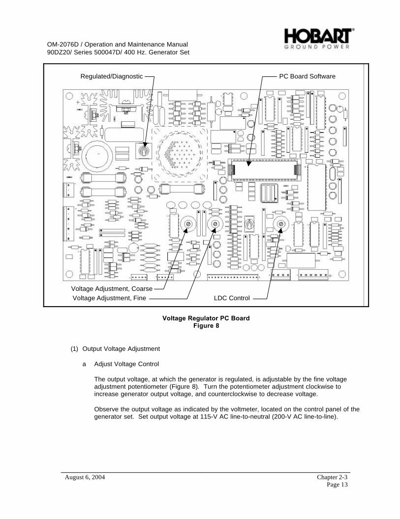
OM-2076D / Operation and Maintenance Manual90DZ20/ Series 500047D/ 400 Hz. Generator Set
August 6, 2004 Chapter 2-3Page 13
Regulated/Diagnostic
Voltage Adjustment, Coarse
Voltage Adjustment, Fine LDC Control
PC Board Software
Voltage Regulator PC BoardFigure 8
(1) Output Voltage Adjustment
a Adjust Voltage Control
The output voltage, at which the generator is regulated, is adjustable by the fine voltageadjustment potentiometer (Figure 8). Turn the potentiometer adjustment clockwise toincrease generator output voltage, and counterclockwise to decrease voltage.
Observe the output voltage as indicated by the voltmeter, located on the control panel of thegenerator set. Set output voltage at 115-V AC line-to-neutral (200-V AC line-to-line).
OM-2076D / Operation and Maintenance Manual90DZ20/ Series 500047D/ 400 Hz. Generator Set
August 6, 2004 Chapter 2-3Page 14
b Adjust Line Drop Compensation
Adjustment of line drop compensation is made with the line drop compensation potentiometer(Figure 8). Turning the potentiometer knob clockwise increases the magnitude of thecompensation, and turning the potentiometer knob counterclockwise decreases themagnitude (A graduated nameplate for specified cable lengths is included for quickreference.). To adjust the line drop compensation, proceed as follows:
• Connect the generator set output cables to a load. Load the generator set with thelargest available three-phase load of rated power factor not exceeding the maximumrating of the generator set.
• Measure output voltage at the load end of the cables. If the load voltage rises or dropsmore than 1% at the load end of the cables, decrease or increase the line dropcompensation until the regulation is flat (115-V AC line-to-neutral and 200-V AC line-to-line).
• If the line drop compensation adjustments have affected the no-load voltage output,adjust the fine output voltage control potentiometer to the desired value.
(2) Test the Voltage Regulator
After necessary adjustments have been completed, re-test the voltage regulator as follows:
a Connect a voltmeter at the load end of the generator output cables.b Operate the generator set at no-load and observe voltage reading.c Operate the generator set under load and observe voltage reading.d Voltage under load and no load should vary no more than 1% at the load end of the cables.
c) Basic Engine Adjustments
Adjustment procedures applicable to the diesel engine are included in the engine manufacturer’soperation manual, which is referenced in Chapter 5. Specific information for these engines is listed inFigure 2. Refer to the engine operation manual for detailed information on the following engineadjustments.
(1) Exhaust valve adjustment(2) Fuel injector timing adjustment(3) Engine idle speed adjustment
Engine idle speed is programmed at the factory. If adjustment is required, contact the localengine distributor. The recommended idle speed is 1000 RPM, +/- 25 RPM.
NOTE: A stroboscope is required for engine idle speed checks.
(4) Engine speed limiting adjustment
The speed limiting adjustment is also set and sealed at the factory. Speed should be limited toapproximately 2350 RPM. If adjustment is required, contact your local engine distributor.

OM-2076D / Operation and Maintenance Manual90DZ20/ Series 500047D/ 400 Hz. Generator Set
August 6, 2004 Chapter 2-3Page 15
d) Engine Accessories Adjustment
(1) Alternator and fan belt adjustment
Refer to Section 2-1 and engine manufacturer’s manual.
ENGINE
Manufacturer Deutz CorporationModel No. BF06M1013ECType Rotary, 6 cylinder, 4 cycle diesel, electronic controledHorsepower 218 hp (163 kW)Idle speed 850 or 1000 ± 50 rpmHigh speed limiting 2350 ± 75 rpmNormal governed speed 2000 rpmLubricating oil capacity (w/ filter) 22 quarts (21 liters)Coolant capacity system 40 quarts (37.8 liters)
Specifications and CapabilitiesFigure 9
4) Generator and Exciter Test
The generator fields and exciter stator may be tested with a Kelvin bridge. This is a double-bridge typeinstrument required for the very low resistance’s encountered in this test. It is understood that zero (0)resistance indicates a SHORT CIRCUITED condition. An infinite resistance reading indicates an OPENCIRCUITED condition. See Figure 10 for resistance values.
a) Disconnect generator stator leads at the output module panel.
b) Disconnect the two black exciter field leads from terminal block mounted on output module panel.
c) Check resistance and compare to values given in Figure 5.
Test Connection Resistance (Ohms)
Generator Stator Phase A to N (G1)* 0.0026Generator Stator Phase B to N (G1)* 0.0026Generator Stator Phase C to N (G1)* 0.0026Exciter Stator Field (L2) 29A - B, B - C, C - A Exciter Armature (G2) 0.041Generator Revolving Field (L1) 2.1
*NOTE: The two leads of a phase must be connected when test is made. Take readings when unitis cold and in an ambient temperature of 70 ºF (21ºC.).
Generator and Exciter Test ReadingsFigure 10
OM-2076D / Operation and Maintenance Manual90DZ20/ Series 500047D/ 400 Hz. Generator Set
August 6, 2004 Chapter 2-3Page 16
5) Diode Test
Test values for diodes are not given here because they could be misleading. Test values may vary evenbetween diodes of the same part number, rating, and manufacturer. General instructions for testingdiodes are as follows:
a) Disconnect exciter windings from diode lead(s).
b) Use a good quality ohmmeter. An instrument, which indicates 50 ohms at the center of the scale, ispreferable.
NOTE: Make certain the battery is in good condition and the pointer is adjusted to zero when the testlead points are shorted together.
c) Hold one ohmmeter lead point on the threaded end of the diode. Hold the other lead point on thewire terminal end. Observe and note the indicated resistance. Now reverse the lead connection onthe diode. Again observe and note the ohmmeter indicated resistance. Generally speaking, if aninfinite or very high resistance was indicated with the leads connected one way and a low, readableresistance was indicated with the leads connected the opposite way, the diode may be consideredgood.
6) Testing the Transformer-Rectifier (Optional, See Appendix A)
The 28.5 VDC transformer-rectifier is an optional add-on to the GPU. See Appendix A for more details onthe adjustment and test of the transformer-rectifier.
OM-2076D / Operation and Maintenance Manual90DZ20/ Series 500047D/ 400 Hz. Generator Set
August 6, 2004 Chapter 2-4Page 1
Section 4 Troubleshooting Procedures
1) General
The Troubleshooting Chart (See Appendix A for the 28.5 VDC Transformer-Rectifier troubleshootinginformation.) and Fault Code Chart, located in this section, covers the common faults and malfunctionsthat you may find during operation or maintenance of this equipment. The charts may not list all faultsand malfunctions that may occur. If a fault of malfunction is not listed in the chart, start looking for thecause at the source of power in the affected circuit. Refer to the schematic and connection diagrams inChapter 5. Test the circuit, step by step, until the source of the malfunction is isolated.
The Fault Code Chart is arranged under 2 headings: Commands and Faults. Commands display theoperation mode at the time a fault code is triggered.
The Troubleshooting Chart is arranged under 3 headings: Trouble Symptom and Condition, ProbableCause, and Test Check and/or Remedy. Trouble(s), Symptom(s), and Condition(s) are described andnumbered. Probable Cause(s) are indented to the right and listed in numbered steps below ProbableCause. Test Check and/or Remedy provides instructions for correcting the malfunction, and is listedbelow each Test or Inspection procedure. Tests and inspections called for in the Troubleshooting Chartare to be performed as described in Chapter 2, Section 1-3, of this manual.
2) Equipment for Troubleshooting
WARNINGExercise extreme care to avoid contact with high voltage leads and components.High voltage can kill!
CAUTIONMaintenance personnel must be very careful when performing terminal-to-terminalchecks to be certain the proper terminals are being used, especially when usingjumper leads. Damage to electrical components may result from the application ofimproper voltage and current.
A good quality multi-scale voltmeter is the only instrument required for troubleshooting. At least twojumper leads with alligator, or similar clips, will be required. The engine electrical system may beused as a 12 VDC power source.
3) Parts Replacement
To lessen end item down time, and to get a faulty machine back on line as quickly as possible, the blackbox concept of parts replacement is reflected in the Troubleshooting and Fault Code Chart. For example,if a component on a control box PC board is defective, the quickest way to remedy the situation is toreplace the complete PC board and send the old to stock. Some of the assemblies that tend to lendthemselves to this concept are:
• Voltage regulator PC Board (REG)• Control PC board (CTL)• Engine Specific PC Board (ESB)• Enigne Interface PC Board (EIB)• LED PC Board (LED)• 28.5 VDC Transformer-Rectifier PC Board (TRB) [Optional, See Appendix A]
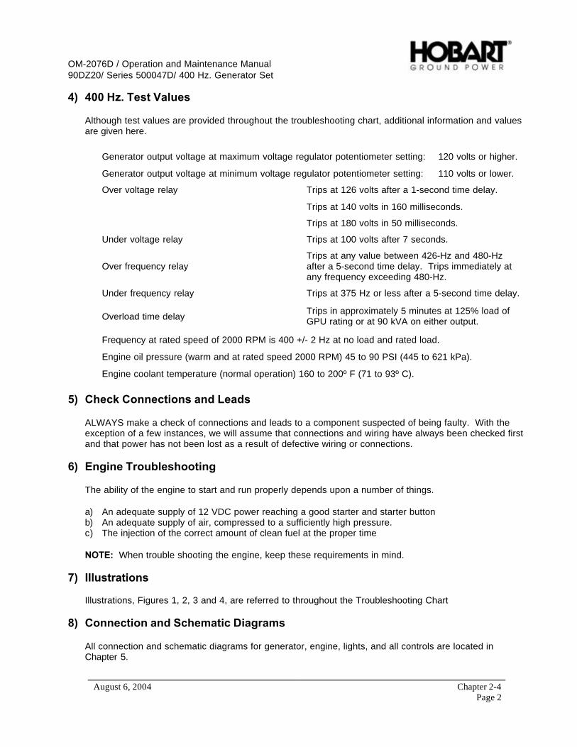
OM-2076D / Operation and Maintenance Manual90DZ20/ Series 500047D/ 400 Hz. Generator Set
August 6, 2004 Chapter 2-4Page 2
4) 400 Hz. Test Values
Although test values are provided throughout the troubleshooting chart, additional information and valuesare given here.
Generator output voltage at maximum voltage regulator potentiometer setting: 120 volts or higher.
Generator output voltage at minimum voltage regulator potentiometer setting: 110 volts or lower.
Over voltage relay Trips at 126 volts after a 1-second time delay.
Trips at 140 volts in 160 milliseconds.
Trips at 180 volts in 50 milliseconds.
Under voltage relay Trips at 100 volts after 7 seconds.
Over frequency relayTrips at any value between 426-Hz and 480-Hzafter a 5-second time delay. Trips immediately atany frequency exceeding 480-Hz.
Under frequency relay Trips at 375 Hz or less after a 5-second time delay.
Overload time delayTrips in approximately 5 minutes at 125% load ofGPU rating or at 90 kVA on either output.
Frequency at rated speed of 2000 RPM is 400 +/- 2 Hz at no load and rated load.
Engine oil pressure (warm and at rated speed 2000 RPM) 45 to 90 PSI (445 to 621 kPa).
Engine coolant temperature (normal operation) 160 to 200º F (71 to 93º C).
5) Check Connections and Leads
ALWAYS make a check of connections and leads to a component suspected of being faulty. With theexception of a few instances, we will assume that connections and wiring have always been checked firstand that power has not been lost as a result of defective wiring or connections.
6) Engine Troubleshooting
The ability of the engine to start and run properly depends upon a number of things.
a) An adequate supply of 12 VDC power reaching a good starter and starter buttonb) An adequate supply of air, compressed to a sufficiently high pressure.c) The injection of the correct amount of clean fuel at the proper time
NOTE: When trouble shooting the engine, keep these requirements in mind.
7) Illustrations
Illustrations, Figures 1, 2, 3 and 4, are referred to throughout the Troubleshooting Chart
8) Connection and Schematic Diagrams
All connection and schematic diagrams for generator, engine, lights, and all controls are located inChapter 5.

OM-2076D / Operation and Maintenance Manual90DZ20/ Series 500047D/ 400 Hz. Generator Set
August 6, 2004 Chapter 2-4Page 3
9) GPU Control Monitoring
The GPU control system performs complete diagnostic testing and continuous monitoring of all criticalcircuits and operating electrical values. If the control system senses a problem with one of the circuits orif any of the electrical values exceeds its safe operating limit, the control system will shut the GPU down,or may allow the GPU to continue operation depending on the severity of the condition.
a) Commands
The ongoing operations conducted by the GPU are driven by the list of commands in Table 1. Thecontrol PC board communicates these commands to all of the PC boards in the GPU. The first half ofthe fault code identifies the command that was present when the fault occurred.
Commands
01.\
39.Self-Test Mode
40. Engine Start Mode
50. Engine Idle Mode
70. Engine Run Mode
80. Engine Shutdown Mode
90. Engine Stop Mode
99. System Off Mode
Operating CommandsTable 1
(1) Self-Test Mode
When power is first applied to the control circuit, the GPU performs complete self diagnostics ofthe internal circuitry. During this self test, the GPU will perform the commands listed in theenclosed charts. When a fault is detected during the self test, the current “COMMAND” anddetected “FAULT” are displayed on the fault code display.
(2) Engine Start Mode
When the “ENGINE START” push-button is activated, the engine’s starter and the engine’s ECMwill be energized.
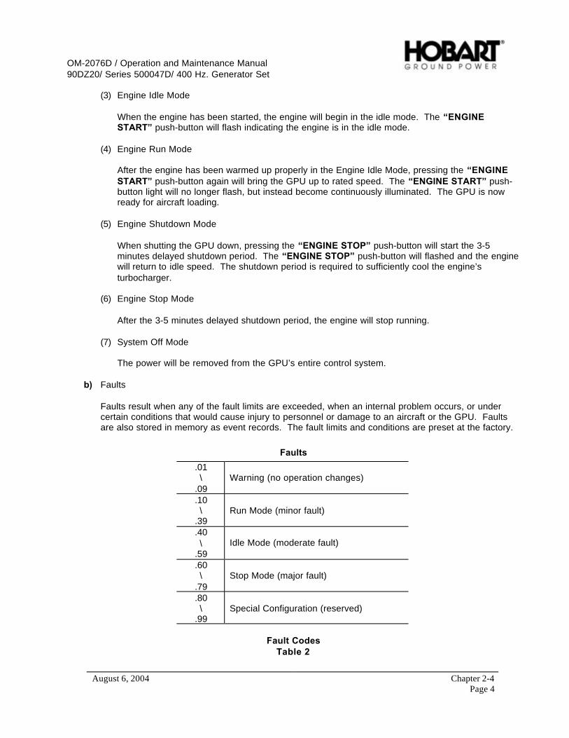
OM-2076D / Operation and Maintenance Manual90DZ20/ Series 500047D/ 400 Hz. Generator Set
August 6, 2004 Chapter 2-4Page 4
(3) Engine Idle Mode
When the engine has been started, the engine will begin in the idle mode. The “ENGINESTART” push-button will flash indicating the engine is in the idle mode.
(4) Engine Run Mode
After the engine has been warmed up properly in the Engine Idle Mode, pressing the “ENGINESTART” push-button again will bring the GPU up to rated speed. The “ENGINE START” push-button light will no longer flash, but instead become continuously illuminated. The GPU is nowready for aircraft loading.
(5) Engine Shutdown Mode
When shutting the GPU down, pressing the “ENGINE STOP” push-button will start the 3-5minutes delayed shutdown period. The “ENGINE STOP” push-button will flashed and the enginewill return to idle speed. The shutdown period is required to sufficiently cool the engine’sturbocharger.
(6) Engine Stop Mode
After the 3-5 minutes delayed shutdown period, the engine will stop running.
(7) System Off Mode
The power will be removed from the GPU’s entire control system.
b) Faults
Faults result when any of the fault limits are exceeded, when an internal problem occurs, or undercertain conditions that would cause injury to personnel or damage to an aircraft or the GPU. Faultsare also stored in memory as event records. The fault limits and conditions are preset at the factory.
Faults
.01\
.09Warning (no operation changes)
.10\
.39Run Mode (minor fault)
.40\
.59Idle Mode (moderate fault)
.60\
.79Stop Mode (major fault)
.80\
.99Special Configuration (reserved)
Fault CodesTable 2

OM-2076D / Operation and Maintenance Manual90DZ20/ Series 500047D/ 400 Hz. Generator Set
August 6, 2004 Chapter 2-4Page 5
(1) Warning
Warning faults are faults that occur and have no effect on the operation of the GPU. An examplewould be an intake air restriction fault due to a dirty filter. Although the GPU will continue tooperate, the fault will appear on the fault code display. Pressing the “TEST/RESET” push buttonor shutting down the GPU will reset the fault.
(2) Run Mode
Run mode faults that occur will remove power form the aircraft but will not change the operatingspeed of the engine. An example would be an over voltage fault. Although the contactors willopen and remove power from the aircraft, the engine will remain at rated speed, and the fault willappear on the fault code display, along with the appropriate command. Pressing the“TEST/RESET” push button or shutting down the GPU will reset the fault.
(3) Idle Mode
Idle mode faults that occur will remove power form the aircraft and drop the operating speed ofthe engine to the idle setting. A possible example (depending on customer configuration) wouldbe a high temperature fault. The contactors will open and remove power from the aircraft, theengine will drop to its idle speed, and the fault will appear on the fault code display, along with theappropriate command. Pressing the “TEST/RESET ” push button or shutting down the GPU willreset the fault.
(4) Stop Mode
Stop mode faults that occur will remove power form the aircraft and shut the engine down. Anexample would be a low oil pressure fault. The contactors will open and remove power from theaircraft, the engine will shut down, and the fault will appear on the fault code display, along withthe appropriate command. Pressing the “TEST/RESET” push button or shutting down the GPUwill reset the fault.
(5) Special Configuration
These fault codes are reserved for special customer configurations. Contact the factory forinformation.
c) Fault Code Display
The numbers that appear in the “FAULT CODE” display are used for troubleshooting the GPU. Toread the four-digit fault code properly, it must be understood that the first two digits represent one halfof the fault code and the last two digits represent the other half.
• The first two digits on the left side of the Fault Code represent the Command.• The two digits on the right side of the Fault Code represent the Fault Condition.

OM-2076D / Operation and Maintenance Manual90DZ20/ Series 500047D/ 400 Hz. Generator Set
August 6, 2004 Chapter 2-4Page 6
Fault Meter DisplayFigure 1
d) Operation Monitoring
While applying power to an aircraft, the GPU continually monitors all critical circuits and operatingelectrical values.
During 400 Hz AC and 28.5 VDC (if supplied) operation, the GPU continually performs Command“70” (Engine Run Mode). When a fault is detected during operation, this Command and the detectedFault are indicated in the “FAULT CODE” display.
By referencing the Command and Fault Code chart, the GPU state and exact fault can bedetermined. When the fault is reset, and the GPU restarted, the GPU may often detect the fault againrevealing additional information. This method yields a high degree of troubleshooting accuracy.
Fault meter display example shown above: If the engine shuts down with the above fault code,“70.67”, the engine ceases operation due to high coolant temperatures in the engine. The “70”represents the command the GPU was executing at the time of the fault and shutdown (Command“70” indicates an Engine Run Mode command.). The “67” represents the fault code that indicates theaction taken by the control system upon faulting (Fault “67” indicates a Stop Mode fault which shutsthe GPU down.).
70.67
Command Fault
Fault Codes

OM-2076D / Operation and Maintenance Manual90DZ20/ Series 500047D/ 400 Hz. Generator Set
August 6, 2004 Chapter 2-4Page 7
12
3 4
5
6 8 7,10 11,1010,12
139 15 1617
1. Fuel Gage (M13)2. Front Panel3. Engine Coolant Temperature Gauge (M24)4. Running Time Meter (M4)5. Oil Pressure Gage (M25)6. Battery Voltmeter (M5)7. Frequency Meter (M3)8. Control Panel Label9. Fault Code Meter (M6)
10. Strip Lights (DS60-DS62) (3) [Not Shown]11. AC Generator Ammeter (M1)12. AC Voltmeter (M2)13. Adjustable Grip Latch14. Control Panel Door Hinge [Not Shown]15. DC Voltmeter [Optional with TR]16. DC Ammeter [Optional with TR]17. Front LED PC Board (A5) [Shown Opposite Side]
Control Panel DoorFigure 2

OM-2076D / Operation and Maintenance Manual90DZ20/ Series 500047D/ 400 Hz. Generator Set
August 6, 2004 Chapter 2-4Page 8
1245678910 3
1. Meter Selector Switch (S3)2. Test/Reset Switch (S77)3. Engine Stop Switch (S76)4. DC Starting Current Switch (S431) [Optional with TR]5. DC Output Contactor Switch (S430) [Optional with TR]
6. AC Output No. 2 (S275) [if applicable]7. AC Output No. 1 (S75)8. Engine Start Switch (S24)9. Air Intake Heater Switch (S79)10. Panel Light Switch (S74)
Control Push-Button Switch PanelFigure 3

OM-2076D / Operation and Maintenance Manual90DZ20/ Series 500047D/ 400 Hz. Generator Set
August 6, 2004 Chapter 2-4Page 9
2
3
1
4
5
6
711 9 810
1. Control Box Wrapper2. Engine Specific PC Board [ESB] (A1)3. Engine Interface PC Board [EIB] (A2)4. Digital Control PC Board [CTL] (A3)5. Voltage Regulator PC Board [REG] (A4)6. Transformer-Rectifier PC Board [TRB] (A404) {Optional}
7. +5, -12 VDC Power Supply (PS1)8. Circuit Breaker Support Bracket9. Marker Lights Circuit Breaker, 10 A (CB1)10. Engine Circuit Breaker, 10 A (CB4)11. Controls Circuit Breaker, 5 A (CB7)
Control Box Interior ComponentsFigure 4

OM-2076D / Operation and Maintenance Manual90DZ20/ Series 500047D/ 400 Hz. Generator Set
August 6, 2004 Chapter 2-4Page 10
Trouble, Symptom, Condition Probable Cause Test, Check, and/or Remedy
Engine Controls
a. Battery discharged, or loosebattery or ground connection.
Check voltage across batteries.Voltage should be approximately12.8 volts DC. Check all batteryterminals. Be sure 12.8 volts DCis reaching solenoid input terminal.
b. Electrical defect in starter. Momentarily connect a largecapacity jumper cable (No. 1/0minimum) between hot side ofstarter solenoid and starter inputterminal. If starter does not crankengine, proceed to step c. Ifstarter does crank engine, proceedto step e.
c. Mechanical defect in starter. Remove starter motor from engineand apply 12 VDC to test it. If itdoesn’t operate, it is defective.Replace it. If starter motor doesoperate, proceed to step d.
d. Internal seizure. If battery and starter are good andstarter is unable to crank theengine, internal seizure isindicated. Attempt to hand crankengine with a ¾-inch square driveon a long flex handle oncrankshaft pulley. If engine cannotbe turned one complete revolution,internal seizure is indicated.Remove engine and contact theengine manufacturer and/ornearest dealer.
e. Defective starter solenoid. Momentarily connect a largecapacity jumper cable (No. 1/0minimum) between the auxiliarysolenoid terminals (one on eachside). If engine does not crank,replace starter solenoid. If enginecranks, proceed to step f below.
1. Engine will not start. Starterwill NOT crank engine.
f. Defective auxiliary startersolenoid.
Momentarily connect a small lugjumper on front of auxiliarysolenoid to the battery terminal ofthe auxiliary starter If engine doesnot crank, replace auxiliary startersolenoid. If engine cranks,proceed to step g below.
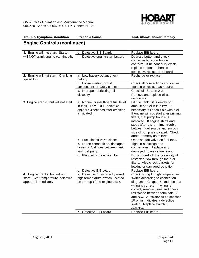
OM-2076D / Operation and Maintenance Manual90DZ20/ Series 500047D/ 400 Hz. Generator Set
August 6, 2004 Chapter 2-4Page 11
Trouble, Symptom, Condition Probable Cause Test, Check, and/or Remedy
Engine Controls (continued)
g. Defective EIB Board. Replace EIB board.1. Engine will not start. Starterwill NOT crank engine (continued). h. Defective engine start button. Depress button and check
continuity between buttoncontacts. If no continuity exists,replace button. If there iscontinuity, replace EIB board.
a. Low battery output checkbattery.
Recharge or replace.
b. Loose starting circuitconnections or faulty cables.
Check all connections and cables.Tighten or replace as required.
2. Engine will not start. Crankingspeed low.
c. Improper lubricating oilviscosity
Check oil, Section 2-2.Remove and replace oil asnecessary.
a. No fuel or insufficient fuel levelin tank. Low FUEL indicationappears 3 seconds after crankingis initiated.
Fill fuel tank if it is empty or ifamount of fuel in it is low. Ifnecessary, fill each filter with fuel.If engine will not start after primingfilters, fuel pump trouble isindicated. If engine starts andstops after a short time, troublebetween fuel source and suctionside of pump is indicated. Checkand/or remedy as follows.
b. Fuel shutoff valve closed. Open shutoff valve on fuel tank.c. Loose connections, damagedhoses or fuel lines between tankand fuel pump
Tighten all fittings andconnections. Replace anydamaged hoses or fuel links.
d. Plugged or defective filter. Do not overlook the possibility ofrestricted flow through the fuelfilters. Also check gaskets forleaking or damaged condition.
3. Engine cranks, but will not start.
e. Defective EIB board. Replace EIB board.a. Defective or incorrectly wiredhigh temperature switch, locatedon the top of the engine block.
Check wiring to high temperatureswitch according to connectiondiagram in Chapter 5, and see thatwiring is correct. If wiring iscorrect, remove wires and checkresistance between terminals Cand N.O. A resistance of less than10 ohms indicates a defectiveswitch. Replace switch ifdefective.
4. Engine cranks, but will notstart. Over-temperature indicationappears immediately.
b. Defective EIB board Replace EIB board.

OM-2076D / Operation and Maintenance Manual90DZ20/ Series 500047D/ 400 Hz. Generator Set
August 6, 2004 Chapter 2-4Page 12
Trouble, Symptom, Condition Probable Cause Test, Check, and/or Remedy
Engine Controls (continued)
5. Engine is hard to start.Cranking speed normal, fuelsupply adequate.
a. Low compression, which maybe caused by any one of following:Sticking or burned exhaust valves,worn or broken compression rings,leaking cylinder head gasket, orimproper valve clearanceadjustment.
Check compression in accordancewith instructions in enginemanufacturer’s operation manual.Overhaul engine to make repairsas necessary.
a. Shutdown circuit may havefunctioned normally to stop enginebecause of low lubricating oilpressure or due to a defective oilpressure switch.
Restart engine, and observe oilpressure gage. If oil pressure is12 psi or more, disconnect wirefrom oil pressure switch terminalN.C. Restart engine. If enginecontinues to run, oil pressureswitch is defective. Replace oilpressure switch. If engine stops,check for following malfunctions:
6. Engine starts. Stops after afew seconds by automaticshutdown.
b. Defective EIB board Replace EIB board.a. Marker light circuit breaker,(CB1) won’t close.
Replace marker lights circuitbreaker (CB1) if defective.
7. All panel and clearance lightsare either always ON or alwaysOFF. b. Defective CTL board Replace CTL board.
8. Engine either goes from ratedspeed to idle speed, or shutsdown.
a. Low fuel was detected or theEIB board could be defective.
Add No. 2 diesel fuel.Replace EIB board.
9. Engine has slow responsetime.
a. Engine needs tune-up Tune-up as required. Refer toengine manufacturer’s operationmanual.
a. Insufficient fuel Check low fuel level in accordancewith engine manufacturer’soperation manual. Repair orreplace parts as required.
b. Faulty injector Check injectors in accordance withengine manufacturer’s operationmanual. See causes of lowcompression listed under ENGINECONTROLS.
c. Low compression pressure Check compression in accordancewith engine manufacturer’soperation manual. See causes oflow compression listed underENGINE CONTROLS.
10. Engine “misses”. Runsunevenly.
d. Air in fuel system Check all fittings to be sure theyare tight and the thread sealant isstill present. Tight the fittings andadd new thread sealant asrequired.
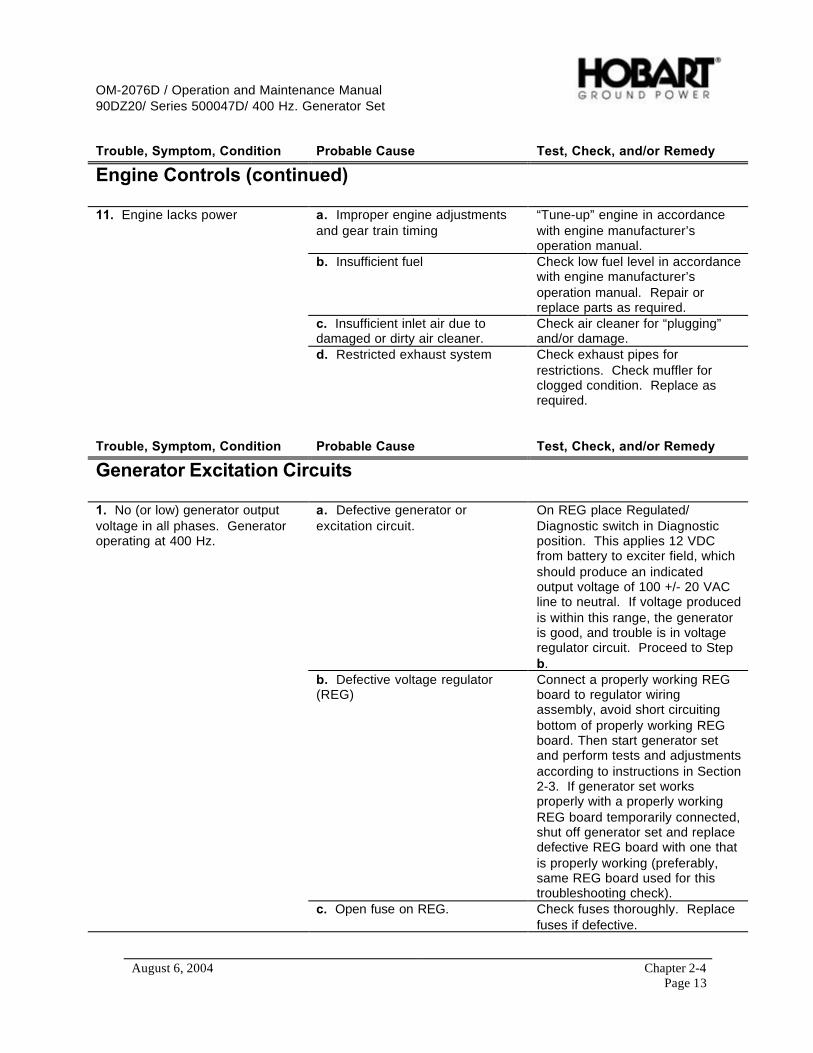
OM-2076D / Operation and Maintenance Manual90DZ20/ Series 500047D/ 400 Hz. Generator Set
August 6, 2004 Chapter 2-4Page 13
Trouble, Symptom, Condition Probable Cause Test, Check, and/or Remedy
Engine Controls (continued)
a. Improper engine adjustmentsand gear train timing
“Tune-up” engine in accordancewith engine manufacturer’soperation manual.
b. Insufficient fuel Check low fuel level in accordancewith engine manufacturer’soperation manual. Repair orreplace parts as required.
c. Insufficient inlet air due todamaged or dirty air cleaner.
Check air cleaner for “plugging”and/or damage.
11. Engine lacks power
d. Restricted exhaust system Check exhaust pipes forrestrictions. Check muffler forclogged condition. Replace asrequired.
Trouble, Symptom, Condition Probable Cause Test, Check, and/or Remedy
Generator Excitation Circuits
a. Defective generator orexcitation circuit.
On REG place Regulated/Diagnostic switch in Diagnosticposition. This applies 12 VDCfrom battery to exciter field, whichshould produce an indicatedoutput voltage of 100 +/- 20 VACline to neutral. If voltage producedis within this range, the generatoris good, and trouble is in voltageregulator circuit. Proceed to Stepb.
b. Defective voltage regulator(REG)
Connect a properly working REGboard to regulator wiringassembly, avoid short circuitingbottom of properly working REGboard. Then start generator setand perform tests and adjustmentsaccording to instructions in Section2-3. If generator set worksproperly with a properly workingREG board temporarily connected,shut off generator set and replacedefective REG board with one thatis properly working (preferably,same REG board used for thistroubleshooting check).
1. No (or low) generator outputvoltage in all phases. Generatoroperating at 400 Hz.
c. Open fuse on REG. Check fuses thoroughly. Replacefuses if defective.
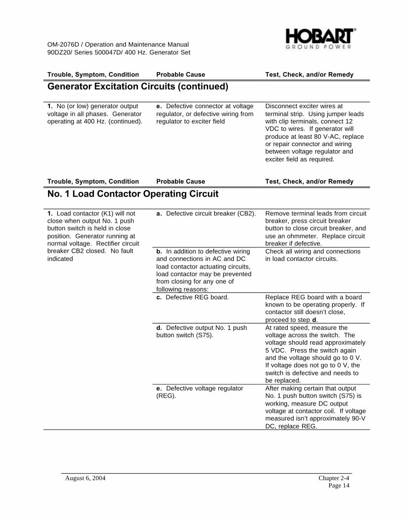
OM-2076D / Operation and Maintenance Manual90DZ20/ Series 500047D/ 400 Hz. Generator Set
August 6, 2004 Chapter 2-4Page 14
Trouble, Symptom, Condition Probable Cause Test, Check, and/or Remedy
Generator Excitation Circuits (continued)
1. No (or low) generator outputvoltage in all phases. Generatoroperating at 400 Hz. (continued).
e. Defective connector at voltageregulator, or defective wiring fromregulator to exciter field
Disconnect exciter wires atterminal strip. Using jumper leadswith clip terminals, connect 12VDC to wires. If generator willproduce at least 80 V-AC, replaceor repair connector and wiringbetween voltage regulator andexciter field as required.
Trouble, Symptom, Condition Probable Cause Test, Check, and/or Remedy
No. 1 Load Contactor Operating Circuit
a. Defective circuit breaker (CB2). Remove terminal leads from circuitbreaker, press circuit breakerbutton to close circuit breaker, anduse an ohmmeter. Replace circuitbreaker if defective.
b. In addition to defective wiringand connections in AC and DCload contactor actuating circuits,load contactor may be preventedfrom closing for any one offollowing reasons:
Check all wiring and connectionsin load contactor circuits.
c. Defective REG board. Replace REG board with a boardknown to be operating properly. Ifcontactor still doesn’t close,proceed to step d.
d. Defective output No. 1 pushbutton switch (S75).
At rated speed, measure thevoltage across the switch. Thevoltage should read approximately5 VDC. Press the switch againand the voltage should go to 0 V.If voltage does not go to 0 V, theswitch is defective and needs tobe replaced.
1. Load contactor (K1) will notclose when output No. 1 pushbutton switch is held in closeposition. Generator running atnormal voltage. Rectifier circuitbreaker CB2 closed. No faultindicated
e. Defective voltage regulator(REG).
After making certain that outputNo. 1 push button switch (S75) isworking, measure DC outputvoltage at contactor coil. If voltagemeasured isn’t approximately 90-VDC, replace REG.

OM-2076D / Operation and Maintenance Manual90DZ20/ Series 500047D/ 400 Hz. Generator Set
August 6, 2004 Chapter 2-4Page 15
Trouble, Symptom, Condition Probable Cause Test, Check, and/or Remedy
No. 1 Load Contactor Operating Circuit (Continued)
1. Load contactor (K1) will notclose when output No. 1 pushbutton switch is held in CLOSEposition. Generator running atnormal voltage. Rectifier circuitbreaker (CB2) closed. No faultindicated. (continued)
f. Defective coil in load contactor(K1).
Disconnect leads at load contactorterminals V and W. Check coilresistance between theseterminals. Resistance should beapproximately 50 ohms. If coil isdefective, replace complete loadcontactor.
a. No. 1 plug interlock EF1 circuiton CTL board could be defective
Place EF Bypass switch, No. 1output in ON position. If loadcontactor remains closed, proceedto step b.
b. 28.5-V DC is not reaching theNo. 1 plug interlock EF1 circuitfrom aircraft for following reasonsd & e:
Proceed as follows to find thecause of this malfunction.
d. Generator to aircraft cableconnector defective or not pluggedinto aircraft receptacle connector.
Inspect cable connector plugthoroughly for damaged E and Fterminals. Be sure plug is fullymated with aircraft receptacleconnector and making goodcontact.
e. Aircraft rejecting power. Check aircraft on-board electricalequipment and controls.
2. Load contactor (K1) will closewhen output No. 1 push buttonswitch is held in CLOSE position.Opens immediately when switch isreleased.
f. Defective contacts in N.O.auxiliary push button switchmounted on right side of contactor(K1).
Connect a jumper lead betweenterminals of N.O. auxiliary switch.If load contactor will now remainclosed, replace N.O. auxiliaryswitch or complete load contactor.
a. A fault has developed in loadcontactor holding circuit.
If load contactor cannot be closedby operation of output No. 1 pushbutton switch (S75), check circuitin accordance with instructions inTrouble, Symptom, Condition 1. Ifload contactor can be closed, butopens as soon as power acceptedswitch (S75) is released, check fortrouble under Trouble 2, above.
3. Load contactor opens duringpower delivery. No fault indicated.
c. Cable accidentallydisconnected from aircraft.
Reconnect cable.
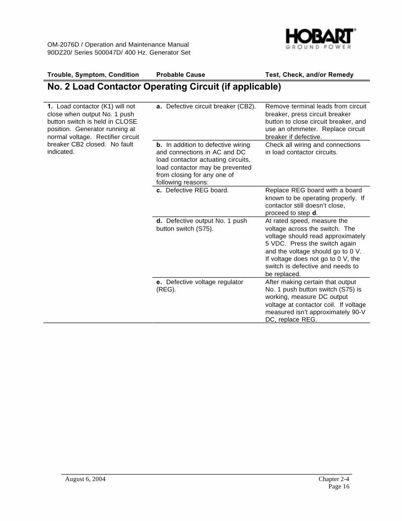
OM-2076D / Operation and Maintenance Manual90DZ20/ Series 500047D/ 400 Hz. Generator Set
August 6, 2004 Chapter 2-4Page 16
Trouble, Symptom, Condition Probable Cause Test, Check, and/or Remedy
No. 2 Load Contactor Operating Circuit (if applicable)
a. Defective circuit breaker (CB2). Remove terminal leads from circuitbreaker, press circuit breakerbutton to close circuit breaker, anduse an ohmmeter. Replace circuitbreaker if defective.
b. In addition to defective wiringand connections in AC and DCload contactor actuating circuits,load contactor may be preventedfrom closing for any one offollowing reasons:
Check all wiring and connectionsin load contactor circuits.
c. Defective REG board. Replace REG board with a boardknown to be operating properly. Ifcontactor still doesn’t close,proceed to step d.
d. Defective output No. 1 pushbutton switch (S75).
At rated speed, measure thevoltage across the switch. Thevoltage should read approximately5 VDC. Press the switch againand the voltage should go to 0 V.If voltage does not go to 0 V, theswitch is defective and needs tobe replaced.
1. Load contactor (K1) will notclose when output No. 1 pushbutton switch is held in CLOSEposition. Generator running atnormal voltage. Rectifier circuitbreaker CB2 closed. No faultindicated.
e. Defective voltage regulator(REG).
After making certain that outputNo. 1 push button switch (S75) isworking, measure DC outputvoltage at contactor coil. If voltagemeasured isn’t approximately 90-VDC, replace REG.

OM-2076D / Operation and Maintenance Manual90DZ20/ Series 500047D/ 400 Hz. Generator Set
August 6, 2004 Chapter 2-4Page 17
Trouble, Symptom, Condition Probable Cause Test, Check, and/or Remedy
No. 2 Load Contactor Operating Circuit (if applicable) [continued]
1. Load contactor (K201) will notclose when output No. 1 pushbutton switch is held in closeposition. Generator running atnormal voltage. Rectifier circuitbreaker (CB2) closed. No faultindicated. (continued)
f. Defective coil in load contactor(K201).
Disconnect leads at load contactorterminals V and W. Check coilresistance between theseterminals. Resistance should beapproximately 50 ohms. If coil isdefective, replace complete loadcontactor.
a. No. 2 plug interlock EF2 circuiton CTL board could be defective
Place EF Bypass switch, No. 1output in ON position. If loadcontactor remains closed, proceedto step b.
b. 28.5-V DC is not reaching theNo. 1 plug interlock EF2 circuitfrom aircraft for following reasonsd & e:
Proceed as follows to find thecause of this malfunction.
d. Generator to aircraft cableconnector defective or not pluggedinto aircraft receptacle connector.
Inspect cable connector plugthoroughly for damaged E and Fterminals. Be sure plug is fullymated with aircraft receptacleconnector and making goodcontact.
e. Aircraft rejecting power. Check aircraft on-board electricalequipment and controls.
2. Load contactor (K201) willclose when output No. 1 pushbutton switch is held in CLOSEposition. Opens immediately whenswitch is released.
f. Defective contacts in N.O.auxiliary push button switchmounted on right side of contactor(K1).
Connect a jumper lead betweenterminals of N.O. auxiliary switch.If load contactor will now remainclosed, replace N.O. auxiliaryswitch or complete load contactor.
a. A fault has developed in loadcontactor holding circuit.
If load contactor cannot be closedby operation of output No. 1 pushbutton switch (S275), check circuitin accordance with instructions inTrouble, Symptom, Condition 1. Ifload contactor can be closed, butopens as soon as power acceptedswitch (S275) is released, checkfor trouble under Trouble 2, above.
3. Load contactor opens duringpower delivery. No fault indicated.
c. Cable accidentallydisconnected from aircraft.
Reconnect cable.
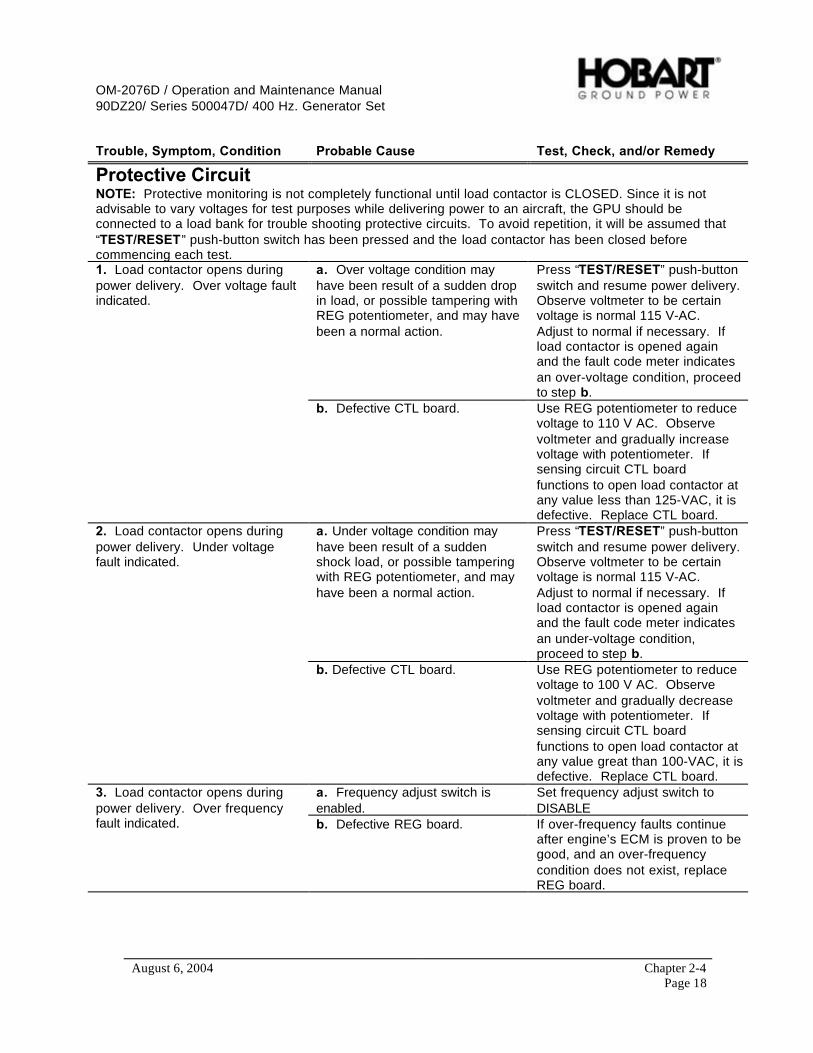
OM-2076D / Operation and Maintenance Manual90DZ20/ Series 500047D/ 400 Hz. Generator Set
August 6, 2004 Chapter 2-4Page 18
Trouble, Symptom, Condition Probable Cause Test, Check, and/or Remedy
Protective CircuitNOTE: Protective monitoring is not completely functional until load contactor is CLOSED. Since it is notadvisable to vary voltages for test purposes while delivering power to an aircraft, the GPU should beconnected to a load bank for trouble shooting protective circuits. To avoid repetition, it will be assumed that“TEST/RESET” push-button switch has been pressed and the load contactor has been closed beforecommencing each test.
a. Over voltage condition mayhave been result of a sudden dropin load, or possible tampering withREG potentiometer, and may havebeen a normal action.
Press “TEST/RESET” push-buttonswitch and resume power delivery.Observe voltmeter to be certainvoltage is normal 115 V-AC.Adjust to normal if necessary. Ifload contactor is opened againand the fault code meter indicatesan over-voltage condition, proceedto step b.
1. Load contactor opens duringpower delivery. Over voltage faultindicated.
b. Defective CTL board. Use REG potentiometer to reducevoltage to 110 V AC. Observevoltmeter and gradually increasevoltage with potentiometer. Ifsensing circuit CTL boardfunctions to open load contactor atany value less than 125-VAC, it isdefective. Replace CTL board.
a. Under voltage condition mayhave been result of a suddenshock load, or possible tamperingwith REG potentiometer, and mayhave been a normal action.
Press “TEST/RESET” push-buttonswitch and resume power delivery.Observe voltmeter to be certainvoltage is normal 115 V-AC.Adjust to normal if necessary. Ifload contactor is opened againand the fault code meter indicatesan under-voltage condition,proceed to step b.
2. Load contactor opens duringpower delivery. Under voltagefault indicated.
b. Defective CTL board. Use REG potentiometer to reducevoltage to 100 V AC. Observevoltmeter and gradually decreasevoltage with potentiometer. Ifsensing circuit CTL boardfunctions to open load contactor atany value great than 100-VAC, it isdefective. Replace CTL board.
a. Frequency adjust switch isenabled.
Set frequency adjust switch toDISABLE
3. Load contactor opens duringpower delivery. Over frequencyfault indicated. b. Defective REG board. If over-frequency faults continue
after engine’s ECM is proven to begood, and an over-frequencycondition does not exist, replaceREG board.
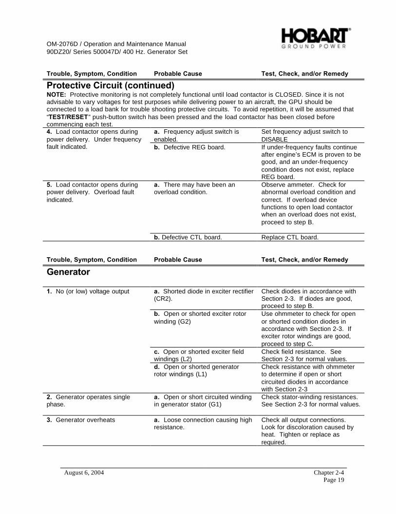
OM-2076D / Operation and Maintenance Manual90DZ20/ Series 500047D/ 400 Hz. Generator Set
August 6, 2004 Chapter 2-4Page 19
Trouble, Symptom, Condition Probable Cause Test, Check, and/or Remedy
Protective Circuit (continued)NOTE: Protective monitoring is not completely functional until load contactor is CLOSED. Since it is notadvisable to vary voltages for test purposes while delivering power to an aircraft, the GPU should beconnected to a load bank for trouble shooting protective circuits. To avoid repetition, it will be assumed that“TEST/RESET” push-button switch has been pressed and the load contactor has been closed beforecommencing each test.
a. Frequency adjust switch isenabled.
Set frequency adjust switch toDISABLE
4. Load contactor opens duringpower delivery. Under frequencyfault indicated. b. Defective REG board. If under-frequency faults continue
after engine’s ECM is proven to begood, and an under-frequencycondition does not exist, replaceREG board.
a. There may have been anoverload condition.
Observe ammeter. Check forabnormal overload condition andcorrect. If overload devicefunctions to open load contactorwhen an overload does not exist,proceed to step B.
5. Load contactor opens duringpower delivery. Overload faultindicated.
b. Defective CTL board. Replace CTL board.
Trouble, Symptom, Condition Probable Cause Test, Check, and/or Remedy
Generator
a. Shorted diode in exciter rectifier(CR2).
Check diodes in accordance withSection 2-3. If diodes are good,proceed to step B.
b. Open or shorted exciter rotorwinding (G2)
Use ohmmeter to check for openor shorted condition diodes inaccordance with Section 2-3. Ifexciter rotor windings are good,proceed to step C.
c. Open or shorted exciter fieldwindings (L2)
Check field resistance. SeeSection 2-3 for normal values.
1. No (or low) voltage output
d. Open or shorted generatorrotor windings (L1)
Check resistance with ohmmeterto determine if open or shortcircuited diodes in accordancewith Section 2-3
2. Generator operates singlephase.
a. Open or short circuited windingin generator stator (G1)
Check stator-winding resistances.See Section 2-3 for normal values.
3. Generator overheats a. Loose connection causing highresistance.
Check all output connections.Look for discoloration caused byheat. Tighten or replace asrequired.
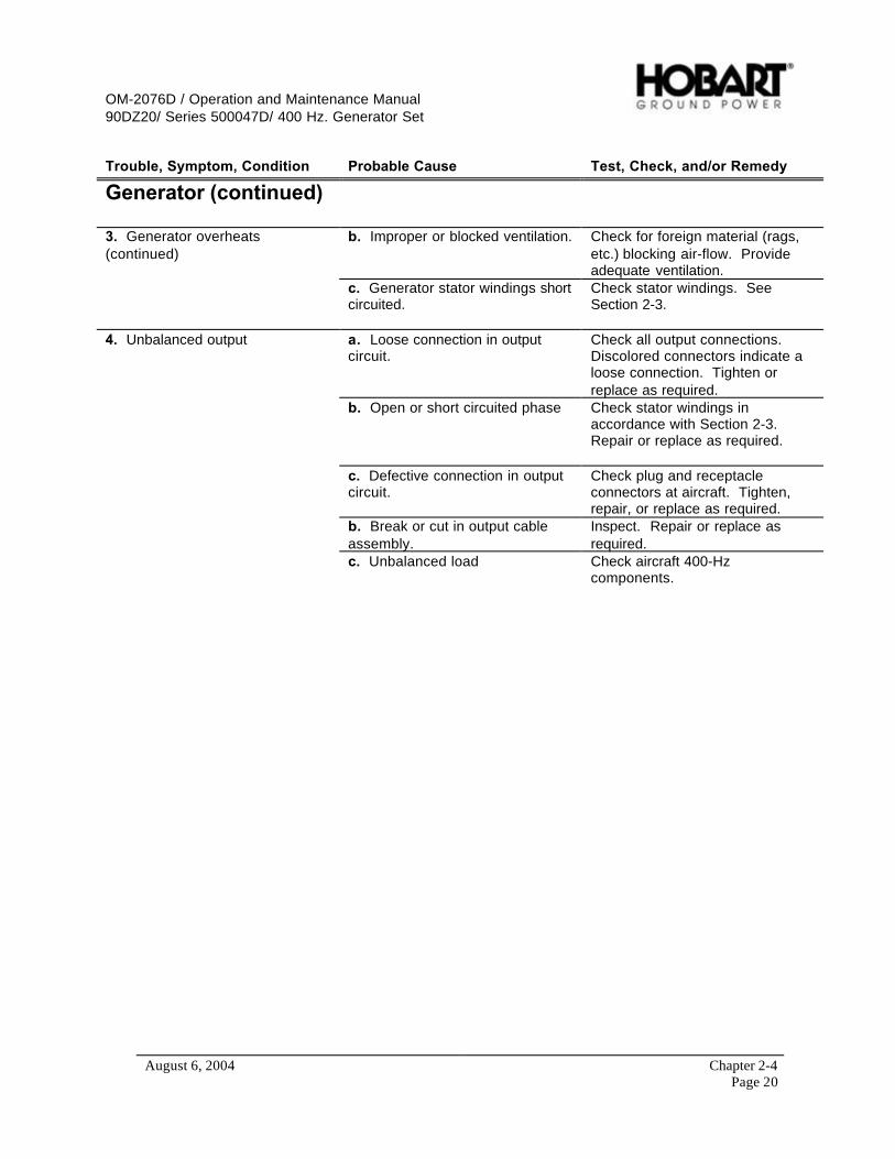
OM-2076D / Operation and Maintenance Manual90DZ20/ Series 500047D/ 400 Hz. Generator Set
August 6, 2004 Chapter 2-4Page 20
Trouble, Symptom, Condition Probable Cause Test, Check, and/or Remedy
Generator (continued)
b. Improper or blocked ventilation. Check for foreign material (rags,etc.) blocking air-flow. Provideadequate ventilation.
3. Generator overheats(continued)
c. Generator stator windings shortcircuited.
Check stator windings. SeeSection 2-3.
a. Loose connection in outputcircuit.
Check all output connections.Discolored connectors indicate aloose connection. Tighten orreplace as required.
b. Open or short circuited phase Check stator windings inaccordance with Section 2-3.Repair or replace as required.
c. Defective connection in outputcircuit.
Check plug and receptacleconnectors at aircraft. Tighten,repair, or replace as required.
b. Break or cut in output cableassembly.
Inspect. Repair or replace asrequired.
4. Unbalanced output
c. Unbalanced load Check aircraft 400-Hzcomponents.
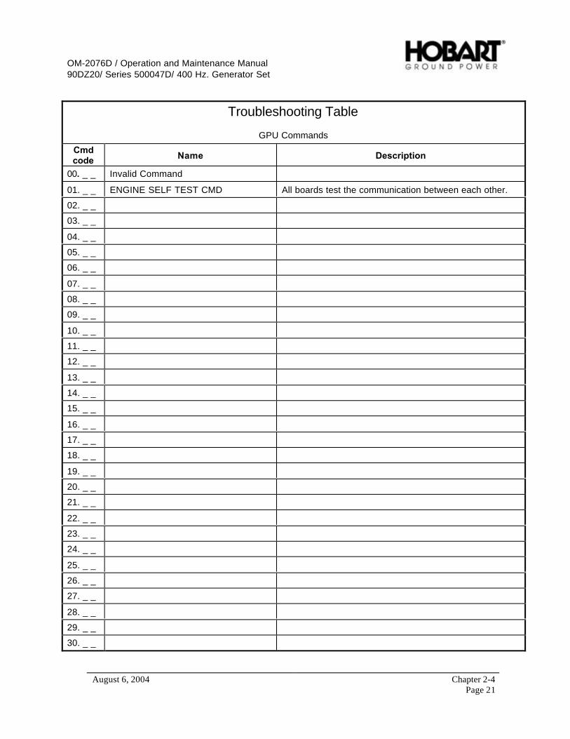
OM-2076D / Operation and Maintenance Manual90DZ20/ Series 500047D/ 400 Hz. Generator Set
August 6, 2004 Chapter 2-4Page 21
Troubleshooting Table
GPU Commands
Cmdcode Name Description
00. _ _ Invalid Command
01. _ _ ENGINE SELF TEST CMD All boards test the communication between each other.
02. _ _
03. _ _
04. _ _
05. _ _
06. _ _
07. _ _
08. _ _
09. _ _
10. _ _
11. _ _
12. _ _
13. _ _
14. _ _
15. _ _
16. _ _
17. _ _
18. _ _
19. _ _
20. _ _
21. _ _
22. _ _
23. _ _
24. _ _
25. _ _
26. _ _
27. _ _
28. _ _
29. _ _
30. _ _
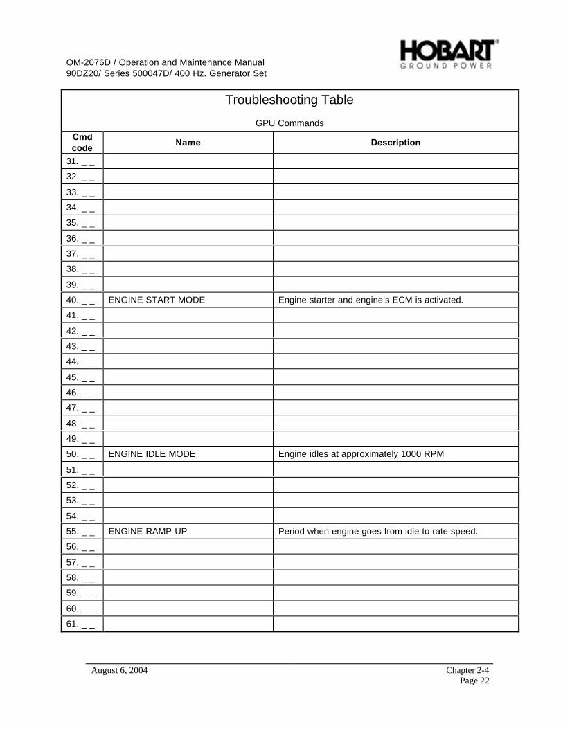
OM-2076D / Operation and Maintenance Manual90DZ20/ Series 500047D/ 400 Hz. Generator Set
August 6, 2004 Chapter 2-4Page 22
Troubleshooting Table
GPU Commands
Cmdcode
Name Description
31. _ _
32. _ _
33. _ _
34. _ _
35. _ _
36. _ _
37. _ _
38. _ _
39. _ _
40. _ _ ENGINE START MODE Engine starter and engine’s ECM is activated.
41. _ _
42. _ _
43. _ _
44. _ _
45. _ _
46. _ _
47. _ _
48. _ _
49. _ _
50. _ _ ENGINE IDLE MODE Engine idles at approximately 1000 RPM
51. _ _
52. _ _
53. _ _
54. _ _
55. _ _ ENGINE RAMP UP Period when engine goes from idle to rate speed.
56. _ _
57. _ _
58. _ _
59. _ _
60. _ _
61. _ _

OM-2076D / Operation and Maintenance Manual90DZ20/ Series 500047D/ 400 Hz. Generator Set
August 6, 2004 Chapter 2-4Page 23
Troubleshooting Table
GPU Commands
Cmdcode
Name Description
62. _ _
63. _ _ REG TEST OUTPUT FREQUENCY Check for 400 Hz. output frequency.
64. _ _
65. _ _ TRB REGULATE DC Check for DC regulation.
66. _ _
67. _ _
68. _ _ CTL TEST OUTPUT Checks the CTL communications.
69. _ _
70. _ _ ENGINE RUN MODE The engine is at rated speed and ready for aircraft load.
71. _ _
72. _ _
73. _ _
74. _ _
75. _ _ ENGINE RAMP DOWN Period when engine goes from rated to idle speed.
76. _ _
77. _ _
78. _ _
79. _ _
80. _ _ ENGINE SHUTDOWN MODE Allows the turbocharger to cooling properly.
81. _ _
82. _ _
83. _ _
84. _ _
85. _ _
86. _ _
87. _ _
88. _ _
89. _ _
90. _ _ ENGINE STOP MODE Engine is brought to a complete stop.
91. _ _
92. _ _
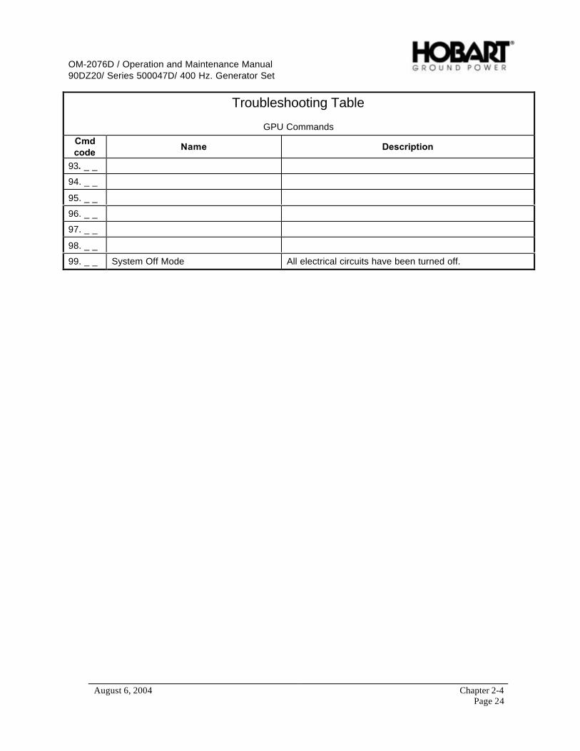
OM-2076D / Operation and Maintenance Manual90DZ20/ Series 500047D/ 400 Hz. Generator Set
August 6, 2004 Chapter 2-4Page 24
Troubleshooting Table
GPU Commands
Cmdcode
Name Description
93. _ _
94. _ _
95. _ _
96. _ _
97. _ _
98. _ _
99. _ _ System Off Mode All electrical circuits have been turned off.
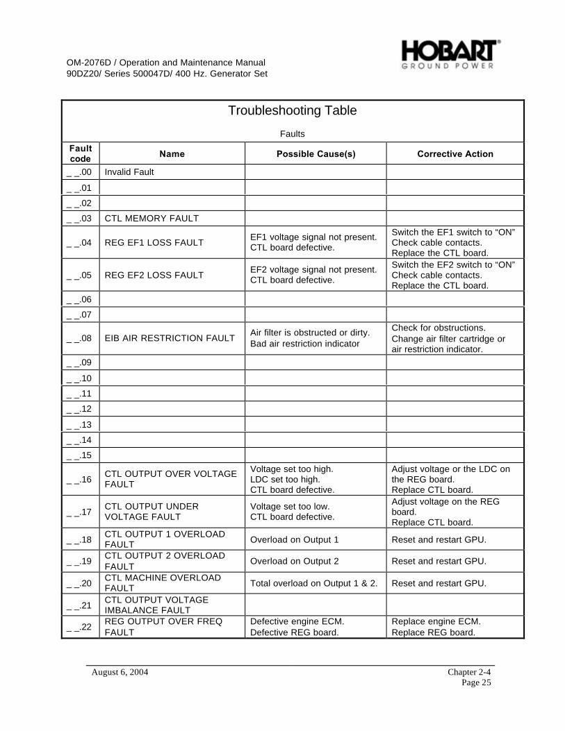
OM-2076D / Operation and Maintenance Manual90DZ20/ Series 500047D/ 400 Hz. Generator Set
August 6, 2004 Chapter 2-4Page 25
Troubleshooting Table
Faults
Faultcode Name Possible Cause(s) Corrective Action
_ _.00 Invalid Fault
_ _.01
_ _.02
_ _.03 CTL MEMORY FAULT
_ _.04 REG EF1 LOSS FAULTEF1 voltage signal not present.CTL board defective.
Switch the EF1 switch to “ON”Check cable contacts.Replace the CTL board.
_ _.05 REG EF2 LOSS FAULTEF2 voltage signal not present.CTL board defective.
Switch the EF2 switch to “ON”Check cable contacts.Replace the CTL board.
_ _.06
_ _.07
_ _.08 EIB AIR RESTRICTION FAULTAir filter is obstructed or dirty.Bad air restriction indicator
Check for obstructions.Change air filter cartridge orair restriction indicator.
_ _.09
_ _.10
_ _.11
_ _.12
_ _.13
_ _.14
_ _.15
_ _.16CTL OUTPUT OVER VOLTAGEFAULT
Voltage set too high.LDC set too high.CTL board defective.
Adjust voltage or the LDC onthe REG board.Replace CTL board.
_ _.17CTL OUTPUT UNDERVOLTAGE FAULT
Voltage set too low.CTL board defective.
Adjust voltage on the REGboard.Replace CTL board.
_ _.18CTL OUTPUT 1 OVERLOADFAULT Overload on Output 1 Reset and restart GPU.
_ _.19CTL OUTPUT 2 OVERLOADFAULT
Overload on Output 2 Reset and restart GPU.
_ _.20CTL MACHINE OVERLOADFAULT Total overload on Output 1 & 2. Reset and restart GPU.
_ _.21CTL OUTPUT VOLTAGEIMBALANCE FAULT
_ _.22REG OUTPUT OVER FREQFAULT
Defective engine ECM.Defective REG board.
Replace engine ECM.Replace REG board.

OM-2076D / Operation and Maintenance Manual90DZ20/ Series 500047D/ 400 Hz. Generator Set
August 6, 2004 Chapter 2-4Page 26
Troubleshooting Table
Faults
Faultcode Name Possible Cause(s) Corrective Action
_ _.23REG OUTPUT UNDER FREQFAULT
Defective engine ECM.Defective REG board.
Replace engine ECM.Replace REG board.
_ _.24 REG CONTACTOR1 FAULTDefective output contactor.Defective REG board.
Replace output contactor.Replace REG board.
_ _.25 REG CONTACTOR 2 FAULTDefective output contactor.Defective REG board.
Replace output contactor.Replace REG board.
_ _.26CTL DC OVER VOLTAGEFAULT
Defective CTL board. Replace CTL board.
_ _.27CTL DC UNDER VOLTAGEFAULT Defective CTL board. Replace CTL board.
_ _.28TRB OUTPUT OVER VOLTAGEFAULT
Voltage set too high.TRB board defective.
Reset and restart GPU.Replace TRB board.
_ _.29TRB OUTPUT UNDERVOLTAGE FAULT
Voltage set too low.TRB board defective.
Reset and restart GPU.Replace TRB board.
_ _.30TRB OUTPUT OVERLOADFAULT DC load over rating of GPU. Reset and restart GPU.
_ _.31 TRB DC CONTACTOR FAULTDefective output contactor.Defective TRB board.
Replace output contactor.Replace TRB board.
_ _.32
_ _.33
_ _.34
_ _.35
_ _.36
_ _.37
_ _.38
_ _.39
_ _.40 CTL ID FAULT Defective CTL board. Replace CTL board.
_ _.41 TRB ID FAULT Defective TRB board. Replace TRB board.
_ _.42 ESB ID FAULT Defective ESB board. Replace ESB board.
_ _.43 REG ID FAULT Defective REG board. Replace REG board.
_ _.44TRB HEATSINK OVERTEMPFAULT
Obstructed cooling air path.Defective thermal switch
Clear air obstruction.Replace switch.
_ _.45TRB TRANSFORMEROVERTEMP FAULT
Obstructed cooling air path.Defective thermal switch
Clear air obstruction.Replace switch.
_ _.46TRB INPUT CONTACTORFAULT
Defective input contactor.Defective TRB board.
Replace input contactor.Replace TRB board.
_ _.47
_ _.48
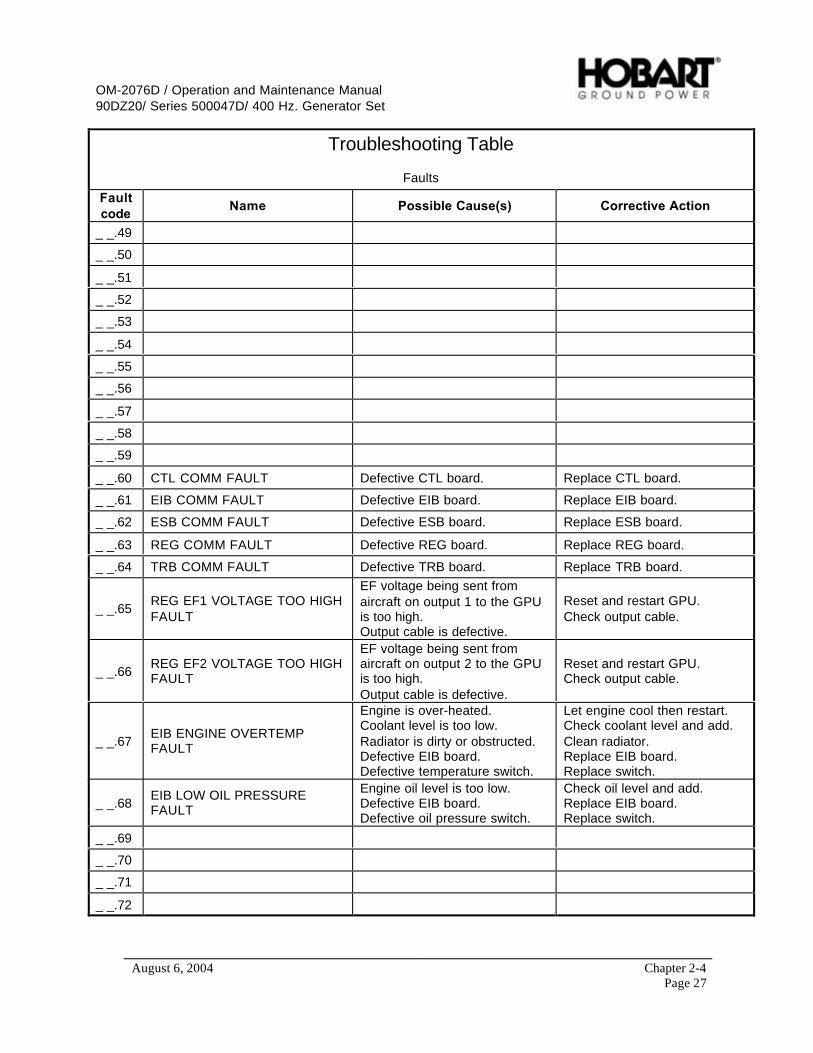
OM-2076D / Operation and Maintenance Manual90DZ20/ Series 500047D/ 400 Hz. Generator Set
August 6, 2004 Chapter 2-4Page 27
Troubleshooting Table
Faults
Faultcode
Name Possible Cause(s) Corrective Action
_ _.49
_ _.50
_ _.51
_ _.52
_ _.53
_ _.54
_ _.55
_ _.56
_ _.57
_ _.58
_ _.59
_ _.60 CTL COMM FAULT Defective CTL board. Replace CTL board.
_ _.61 EIB COMM FAULT Defective EIB board. Replace EIB board.
_ _.62 ESB COMM FAULT Defective ESB board. Replace ESB board.
_ _.63 REG COMM FAULT Defective REG board. Replace REG board.
_ _.64 TRB COMM FAULT Defective TRB board. Replace TRB board.
_ _.65REG EF1 VOLTAGE TOO HIGHFAULT
EF voltage being sent fromaircraft on output 1 to the GPUis too high.Output cable is defective.
Reset and restart GPU.Check output cable.
_ _.66REG EF2 VOLTAGE TOO HIGHFAULT
EF voltage being sent fromaircraft on output 2 to the GPUis too high.Output cable is defective.
Reset and restart GPU.Check output cable.
_ _.67EIB ENGINE OVERTEMPFAULT
Engine is over-heated.Coolant level is too low.Radiator is dirty or obstructed.Defective EIB board.Defective temperature switch.
Let engine cool then restart.Check coolant level and add.Clean radiator.Replace EIB board.Replace switch.
_ _.68EIB LOW OIL PRESSUREFAULT
Engine oil level is too low.Defective EIB board.Defective oil pressure switch.
Check oil level and add.Replace EIB board.Replace switch.
_ _.69
_ _.70
_ _.71
_ _.72

OM-2076D / Operation and Maintenance Manual90DZ20/ Series 500047D/ 400 Hz. Generator Set
August 6, 2004 Chapter 2-4Page 28
Troubleshooting Table
Faults
Faultcode Name Possible Cause(s) Corrective Action
_ _.73
_ _.74
_ _.75
_ _.76
_ _.77
_ _.78
_ _.79
_ _.80
_ _.81
_ _.82
_ _.83
_ _.84
_ _.85
_ _.86
_ _.87
_ _.88
_ _.89
_ _.90
_ _.91
_ _.92
_ _.93
_ _.94
_ _.95
_ _.96
_ _.97
_ _.98
_ _.99

OM-2076D / Operation and Maintenance Manual90DZ20/ Series 500047D/ 400 Hz. Generator Set
August 6, 2004 Chapter 3-1Page 1
Chapter 3 Overhaul/Major Repair
Section 1 Exciter Armature
1) General
This section provides information and instructions for removal and installation of the exciter armatureused on this generator set. Through design improvements, the exciter and rear main bearing can beremoved without removing the generator from the generator set. The name exciter armature refers to theshaft-mounted, revolving three-phase windings of the exciter.
1, 2
3
4
5,6,7,8
9
1. Coupling Key (Not Shown)2. Flex Coupling Assembly3. Generator Housing & Stator Assembly4. Armature Assembly5. Exciter Housing & Coils Assembly
6. Exciter Cover7. Exciter Armature Assembly8. Exciter Key (Not Shown)9. Front Bearing (Located Inside Housing Shown)10. Rear Bearing (Located In Exciter Housing)
General AssemblyFigure 1
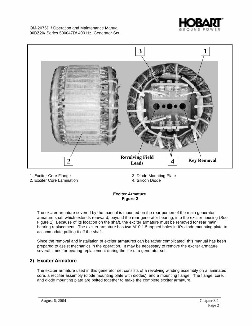
OM-2076D / Operation and Maintenance Manual90DZ20/ Series 500047D/ 400 Hz. Generator Set
August 6, 2004 Chapter 3-1Page 2
13
42 Key RemovalRevolving Field
Leads
1. Exciter Core Flange2. Exciter Core Lamination
3. Diode Mounting Plate4. Silicon Diode
Exciter ArmatureFigure 2
The exciter armature covered by the manual is mounted on the rear portion of the main generatorarmature shaft which extends rearward, beyond the rear generator bearing, into the exciter housing (SeeFigure 1). Because of its location on the shaft, the exciter armature must be removed for rear mainbearing replacement. The exciter armature has two M10-1.5 tapped holes in it’s diode mounting plate toaccommodate pulling it off the shaft.
Since the removal and installation of exciter armatures can be rather complicated, this manual has beenprepared to assist mechanics in the operation. It may be necessary to remove the exciter armatureseveral times for bearing replacement during the life of a generator set.
2) Exciter Armature
The exciter armature used in this generator set consists of a revolving winding assembly on a laminatedcore, a rectifier assembly (diode mounting plate with diodes), and a mounting flange. The flange, core,and diode mounting plate are bolted together to make the complete exciter armature.
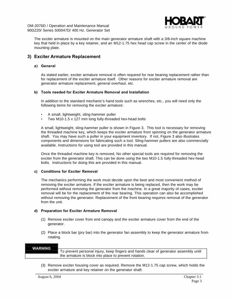
OM-2076D / Operation and Maintenance Manual90DZ20/ Series 500047D/ 400 Hz. Generator Set
August 6, 2004 Chapter 3-1Page 3
The exciter armature is mounted on the main generator armature shaft with a 3/8-inch square machinekey that held in place by a key retainer, and an M12-1.75 hex head cap screw in the center of the diodemounting plate.
3) Exciter Armature Replacement
a) General
As stated earlier, exciter armature removal is often required for rear bearing replacement rather thanfor replacement of the exciter armature itself. Other reasons for exciter armature removal aregenerator armature replacement, general overhaul, etc.
b) Tools needed for Exciter Armature Removal and Installation
In addition to the standard mechanic’s hand tools such as wrenches, etc., you will need only thefollowing items for removing the exciter armature:
• A small, lightweight, sling-hammer puller• Two M10-1.5 x 127 mm long fully-threaded hex-head bolts
A small, lightweight, sling-hammer puller is shown in Figure 3. This tool is necessary for removingthe threaded machine key, which keeps the exciter armature from spinning on the generator armatureshaft. You may have such a puller in your equipment inventory. If not, Figure 3 also illustratescomponents and dimensions for fabricating such a tool. Sling-hammer pullers are also commerciallyavailable. Instructions for using tool are provided in this manual.
Once the threaded machine key is removed, No other special tools are required for removing theexciter from the generator shaft. This can be done using the two M10-1.5 fully-threaded hex-headbolts. Instructions for doing this are provided in this manual.
c) Conditions for Exciter Removal
The mechanics performing the work must decide upon the best and most convenient method ofremoving the exciter armature. If the exciter armature is being replaced, then the work may beperformed without removing the generator from the machine. In a great majority of cases, exciterremoval will be for the replacement of the rear bearing. This operation can also be accomplishedwithout removing the generator. Replacement of the front bearing requires removal of the generatorfrom the unit.
d) Preparation for Exciter Armature Removal
(1) Remove exciter cover from end canopy and the exciter armature cover from the end of thegenerator.
(2) Place a block bar (pry bar) into the generator fan assembly to keep the generator armature fromrotating.
WARNINGTo prevent personal injury, keep fingers and hands clear of generator assembly untilthe armature is block into place to prevent rotation.
(3) Remove exciter housing cover as required. Remove the M12-1.75 cap screw, which holds theexciter armature and key retainer on the generator shaft.
OM-2076D / Operation and Maintenance Manual90DZ20/ Series 500047D/ 400 Hz. Generator Set
August 6, 2004 Chapter 3-1Page 4
(4) Refer to Figures 1 and 2. Disconnect the two rectifier-to-generator field leads. One lead, with aring type terminal, is attached to the rectifier mounting plate with a screw and the other lead goesinto a splice type connector with three other leads coming from the exciter armature windings. Cutthe leads at the connector for removal of the one field lead. Cut as close as possible to theconnection as to preserve lead length for reconnection later during exciter armature installation.
(5) Take EXERCISE CARE to prevent damage to leads. Remove kinks in the two generator leadsas much as possible before starting removal operation (The exciter armature will be sliding overthese leads.).
e) Exciter Armature Removal
(1) Removing the Threaded Key with Sling-Hammer Puller
Refer to Figure 2 for location of threaded machine key. Attachment of the assembled puller to thekey in one operation is not recommended because the weight and bulk of the assembly makethreading the 1/4 inch stud into the key rather clumsy. This could result in cross-threading anddamage to key and stud. It is safer and easier to attach as follows:
a Thread stud (1, Figure 3) into adapter (2) until it bottoms, then thread this assembly (1) and(2) into key until stud bottoms in key threads. Tighten securely.
b If hammer (5) and rod (4) are not already assembled, thread one nut (3) onto adapter end ofrod (4). Thread rod into adapter until it bottoms, then tighten nut securely against adapter.Slide hammer (5) onto rod and install washer (6) and two nuts (3). Thread nuts onto rod untilboth nuts are full threaded and locked together.
WARNINGBe very careful during removal process (slide-hammering) to avoid injury to hands.
CAUTIONExercise care to prevent breaking or damaging stud.
c Position hammer at adapter end of rod.
d Quickly move hammer to outer end of rod with a rapid, slinging motion. HOLD the hammerthrough the entire motion. If hammer is allowed to slide free on the rod, the stud could beDAMAGED or BROKEN.
e Repeat step (c) and (d) as required to loosen key, then remove key and slide-hammer puller.
f After key is removed, apply penetrating oil in the armature and shaft keyways.
(2) Removing the Exciter Armature
CAUTIONLeads may be damaged if armature is turned too far in either direction.
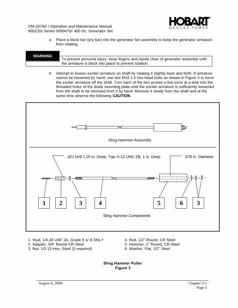
OM-2076D / Operation and Maintenance Manual90DZ20/ Series 500047D/ 400 Hz. Generator Set
August 6, 2004 Chapter 3-1Page 5
a Place a block bar (pry bar) into the generator fan assembly to keep the generator armaturefrom rotating.
WARNINGTo prevent personal injury, keep fingers and hands clear of generator assembly untilthe armature is block into place to prevent rotation.
b Attempt to loosen exciter armature on shaft by rotating it slightly back and forth. If armaturecannot be loosened by hand, use two M10-1.5 hex-head bolts as shown in Figure 4 to forcethe exciter armature off the shaft. Turn each of the two screws a few turns at a time into thethreaded holes of the diode mounting plate until the exciter armature is sufficiently loosenedfrom the shaft to be removed from it by hand. Remove it slowly from the shaft and at thesame time observe the following CAUTION.
1 2 3 4 5 6 3
.578 in. Diameter.421 Drill 1.25 in. Deep; Tap ½-13 UNC-2B, 1 in. Deep
Sling Hammer Assembly
Sling Hammer Components
1. Stud, 1/4-28 UNF 2A, Grade 5 or 8 ONLY2. Adapter, 3/4" Round CR Steel3. Nut, 1/2-13 Hex, Steel (3 required)
4. Rod, 1/2" Round, CR Steel5. Hammer, 2" Round, CR Steel6. Washer, Flat, 1/2" Steel
Sling Hammer PullerFigure 3

OM-2076D / Operation and Maintenance Manual90DZ20/ Series 500047D/ 400 Hz. Generator Set
August 6, 2004 Chapter 3-1Page 6
CAUTIONPay close attention to field leads while pulling exciter armature from shaft. MakeCERTAIN that the leads stay in the 1/2" keyway. One mechanic should watch themconstantly while another operates the puller. Make certain that leads do not catch andbe sure that they slide smoothly through the hole (Figure 2). Straighten leads andremove kinks as required to avoid damage to insulation.
4) Installation Exciter Armature
a) Preparation for Exciter Armature Installation
(1) Clean generator shaft and exciter armature bore. Remove all rust, corrosion, etc.
(2) Make CERTAIN that the leads are tucked into the 1/2" keyway, which is opposite from the 3/8"keyway in the generator armature shaft.
Screw the two M10-1.5 bolts into thethreaded holes of the diode mounting plate toforce the exciter armature off the generatorarmature shaft.
Threaded hole in thediode mounting plate
Threaded hole in thediode mounting plate
(2) M10-1.5 x 127 mm lg. Bolts
GeneratorArmature
Shaft
Exciter Armature RemovalFigure 4
(3) Route the revolving field leads (step 2 above) through exciter armature hole (Figure 2), which isopposite the keyway.
OM-2076D / Operation and Maintenance Manual90DZ20/ Series 500047D/ 400 Hz. Generator Set
August 6, 2004 Chapter 3-1Page 7
(4) Align armature keyway with key in shaft and start armature on shaft.
b) Exciter Armature Installation
(1) If the exciter armature-to-generator shaft fit is such that the exciter armature may be pushed onby hand, push it on very slowly while another mechanic carefully watches and pulls field leadsthrough hole in the exciter armature diode mounting plate. Continue installation until the diodemounting plate contacts the end of the generator shaft. If the exciter armature cannot be pushedon by hand, use a M12-1.75 hex-head bolt and M12-1.75 nut as shown in Figure 5 to pull theexciter armature onto the generator shaft. Put the exciter armature on slowly and at the sametime pull field leads through the hole (Figure 2) in the diode mounting plate. Screw the nut ontothe bolt until it is near the head of the bolt. Insert the bolt through the hole in the center of thediode mounting plate as far as it will go, and screw it into the end of the armature shaft. Screw thenut up against the diode mounting plate. Continue turning the nut until the diode mounting platecontacts the end of the generator shaft, just as is shown in the lower portion of Figure 5. Afterinstallation, remove the bolt and nut.
(2) Connect the two generator field leads to the exciter armature as follows:
a Connect lead with ring type terminal to the screw provided to the mounting plate (Figure 2).
b Connect the other field lead to the three leads coming off of the exciter armature windings.Use parallel splice connector, crimp and solder for a good connection.
c Insulate with sleeving material or wrap with electrical tape.
(3) Install the Machine Key
a Clean the machine key thoroughly. All mounting surfaces must be free of rust, corrosion, oil,grease, etc.
b Apply LOCQUIC primer, No. 47-56 grade T to SIDES of machine key. Do not over prime. Athin film is best. Allow to dry three to four minutes.
c Apply a thin coating of LOCTITE, No. 242 adhesive to SIDES of keyways in shaft andarmature. Be certain to remove any excess from mounting surfaces on shaft and bore ofarmature.
NOTE: Application of “Loctite” is to compensate for any looseness in machine key and keyway (up to0.005 inch). Manufacturers of LOCTITE and other recommended products are listed below.
When exciter armature removal is for the replacement of bearings and no kit is involved, be sure thatLOCTITE is used (No. 242 is recommended), which is a milder adhesive than that recommended inthe manual.
When kits are involved, the correct grade of LOCTITE is included in the Kit.
The application of NEVER-SEEZ to the shaft and armature bore is NOT recommended because thereis a danger that it may mix with and contaminate the LOCTITE. Application of NEVER-SEEZ will beat the customer’s risk. LOCTITE can lose its adhesive and tightening properties if contaminated byrust preventatives, oil, or other lubricants and antirust products.

OM-2076D / Operation and Maintenance Manual90DZ20/ Series 500047D/ 400 Hz. Generator Set
August 6, 2004 Chapter 3-1Page 8
Recommended Products Manufacturers:
• “LOCQUIC” No. 47-56, Primer Grade T• “LOCTITE” No. 40-31, Retaining Compound, Manufactured by Loctite Corporation, Newington,
Connecticut 06111• “NEVER-SEEZ” No. NSBT-8 (8 oz. can), Manufactured by Never-Seez Compound Corporation,
Broadview, Illinois 60153• “NOCO10" Varnish No. T-211 (clear, air dry), Manufactured by Sterling Division of Reichhold
Chemical Incorporated, Marysville, Pennsylvania 17053
d Apply LOCTITE, No. 242 to SIDES of new type threaded machine key. A thin film 0.005 to0.010 inch thick is adequate and desirable.
e Ensure keyways in the generator armature shaft and exciter armature are aligned.
f Insert UNTHREADED end of key in keyways, and then tap lightly until threaded end is flushwith end of shaft.
(4) Secure the exciter armature and key retainer on generator shaft with the M12-1.75 hex head capscrew.
CAUTIONAllow at least 6 hours for complete cure and set up of Loctite before operatingmachine.

OM-2076D / Operation and Maintenance Manual90DZ20/ Series 500047D/ 400 Hz. Generator Set
August 6, 2004 Chapter 3-1Page 9
Exciter armature after installation on shaft
Remove the M12-1.75 bolt and the nut afterinstalling the exciter armature on the generatorarmature shaft.
GeneratorArmature
M12-1.75 threadedhole in armature
Diode MountingPlate
M12-1.75bolt and nut
Exciter Armature InstallationFigure 5

OM-2076D / Operation and Maintenance Manual90DZ20/ Series 500047D/ 400 Hz. Generator Set
August 6, 2004 Chapter 3-1Page 10
This page intentionally left blank.

OM-2076D / Operation and Maintenance Manual90DZ20/ Series 500047D/ 400 Hz. Generator Set
August 6, 2004 Chapter 3-2Page 1
Section 2 Dual Bearing Flexible Coupling
1) General
This manual provides basic instructions for removal, service and installation of a flexible couplingassembly, with generator fan, manufactured by Hobart Ground Power as Part Number 288481. Thisassembly is illustrated in Figure 1. The primary function of this assembly is to couple a Hobart 2000 RPMGenerator to a Diesel engine. The flexible coupling assembly compensates for slight misalignmentbetween the engine and the generator, due to manufacturing tolerances. A tapered bushing and hubsecures the coupling to the generator shaft.
Coupling AssemblyFigure 1
2) Disassembly
Removal of the flexible coupling is required for servicing the generator armature, generator bearings, orthe coupling itself. To remove the coupling, for any reason, it is necessary to separate the engine andgenerator. However, separating the engine and generator while they are installed in the Ground PowerUnit is VERY DIFFICULT because of the limited working space. During removal DO NOT cut any cablesor wires. Disconnect and tag them for re-assembly.
a) Separate Engine and Generator
(1) Refer to Chapter 3, Section 3 for generator assembly removal.

OM-2076D / Operation and Maintenance Manual90DZ20/ Series 500047D/ 400 Hz. Generator Set
August 6, 2004 Chapter 3-2Page 2
Access To Coupling Bolts(for removal or installation)
Figure 2
b) Remove Coupling Assembly
WARNINGTo prevent personal injury, keep fingers and hands clear of generator assembly untilthe armature is block into place to prevent rotation.
(1) Refer to Figure 3. Using a socket wrench, remove all three of the 3/8-16 bolts that secure thebushing to the hub.
(2) Using a 3/16-inch Allen wrench, loosen the set-screw in the bushing to release pressure on thekey.
(3) To separate the bushing from the hub, lubricate two of the 3/8-16 bolts and insert them into thetwo threaded holes in the bushing flange. With socket wrench, screw these bolts into the bushingsuch that the bushing pops loose from the hub, alternating from bolt to bolt.
(4) When the bushing is loose in the hub, use a mallet to GENTLY tap the bushing out of the hub.
(5) Slide the coupling assembly off the shaft and remove the key.
(6) Inspect the coupling assembly components carefully as follows:
a Check for deformed fan blades and damage to the disk.
b Check the rubber exposed at both ends of the bushings for signs of deterioration.
c Check hub and bushing for cracks, evidence of galling, and rust pits. Light rust is permissibleon the bushing and the tapered bore of the hub.

OM-2076D / Operation and Maintenance Manual90DZ20/ Series 500047D/ 400 Hz. Generator Set
August 6, 2004 Chapter 3-2Page 3
d Check the shaft for any damage or deformation where the coupling was mounted on it.
e Check rubber bushing alignment to make sure that the dimension illustrated in Figure 4 ismaintained.
1
5
2
4
3
6
7
8
1. Bolt, 3/8-16 UNC (3)2. Taper Lock Bushing3. Taper Lock Hub4. Tapped holes (2)
5. Key6. Set Screw7. Fan/Coupling Disk8. Armature Shaft
Hub and BushingFigure 3

OM-2076D / Operation and Maintenance Manual90DZ20/ Series 500047D/ 400 Hz. Generator Set
August 6, 2004 Chapter 3-2Page 4
3) Coupling Service
When ordering coupling kits or other parts from your ITW GSE Group Distributor, be sure to include allpertinent information from the unit’s identification plate: Specification No., Model No., and unit rating.
If you have any questions concerning your ITW GSE Group equipment, immediately contact our ServiceDepartment by mail, telephone, e-mail, or FAX.
Write: ITW GSE GroupHobart Ground PowerService Department1177 Trade Road EastTroy, Ohio 45373U.S.A.
Call Inside U.S.A.: (800) 422-4166 (Parts)(800) 422-4177 (Service)
Call From Foreign Countries: (937) 332-5050 (Parts)(937) 332-5060 (Service)
FAX Inside U.S.A. (800) 367-4945
FAX From Foreign Countries: (937) 332-5121
E-Mail : [email protected]
Web Page : www.itwgsegroup.com
a) Replacement Coupling Kit
A replacement coupling kit is available from your ITW GSE Group Distributor. This kit provides areplacement coupling assembly with attaching hardware and installation instructions.
b) Bushing Kit
A bushing kit is available from the ITW GSE Group for replacing the rubber bushing only in thecoupling assembly. However, it should be noted that the finished coupling assembly must bebalanced to 1/2 inch-ounce (360 mg-m) minimum, which may be a problem in the field. If bushingreplacement only is required, the kit part number is 480290. Each kit contains the required number ofbushings, a container of lubrication, and installation instructions.
c) Bushing Replacement
To replace bushings only, proceed as follows:
(1) Press out ALL old bushings.
(2) Refer to Figure 4. Clean each bushing socket thoroughly, removing all traces of old rubber. DONOT scratch or deform the bore of the bushing socket.
OM-2076D / Operation and Maintenance Manual90DZ20/ Series 500047D/ 400 Hz. Generator Set
August 6, 2004 Chapter 3-2Page 5
(3) Shake the container of lubricant (supplied with kit) vigorously and poor it into a small shallow dish.
(4) Roll a bushing in the lubricant to coat it thoroughly. Press it into a socket (from the chamferedend) to the dimension shown in Figure 4.
(5) Repeat step 4 until all new bushings are installed.
(6) Balance the complete coupling assembly to 1/2 inch-ounce (360 mg-m) minimum.
4) Coupling Installation
WARNINGTo prevent personal injury, keep fingers and hands clear of generator assembly untilthe armature is block into place to prevent rotation.
CAUTIONImproper installation of the coupling assembly can result in serious damage to theequipment. Follow these installation instructions exactly.
a) Cleaning
Refer to Figure 5. It is VERY IMPORTANT that the shaft, the bore and the outside of the splitbushing, and the tapered inside of the hub be thoroughly CLEANED FREE OF DIRT AND GRIT.
CAUTIONDo not lubricate any of the surfaces listed above. Lubrication of these surfaces cancause the coupling to fail and damage the generator set. Slight traces of rust arepermissible on the surfaces.
b) Assembly
(1) If an adapter ring must be replaced, remove the bolts that secure it to the flywheel. Discard theold adapter ring and bolts. Install the new adapter ring (see Chapter 4) using the new socket headbolts.
Torque all bolts to 100 ft-lbs (135 N-m).
The new adapter ring and bolts are included in the kit, when required.
(2) Refer to Figure 3. Assemble the bushing into the hub.
CAUTIONMake certain that only the bolts are lubricated, and that no lubricant is permitted to getinside the bushing where the armature shaft will enter the bushing.
(3) Lubricate the three 3/8-16 bolts SPARINGLY and start them into the three (unthreaded) holesfinger-tight.
(4) Slide the generator armature as far as it will go toward the fan housing. Block the armature tomaintain this forward position throughout the installation procedure. Block the armature with awooden block or wedge, being careful not to damage any components of the armature or exciter.
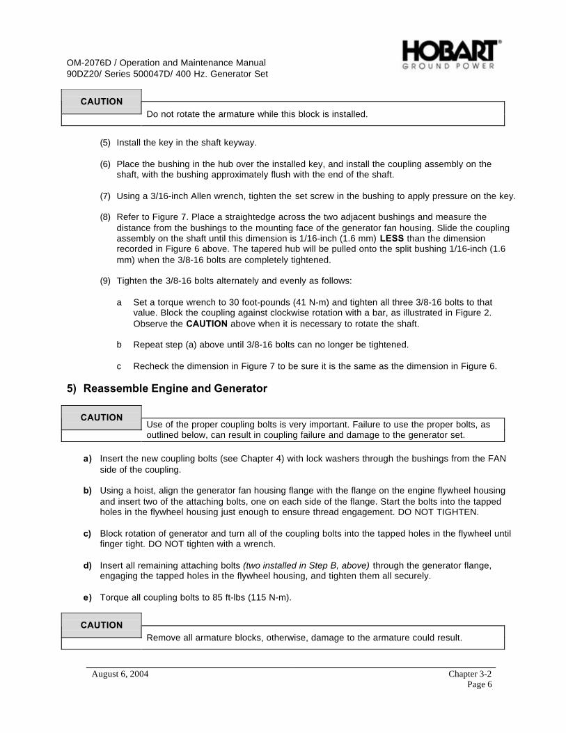
OM-2076D / Operation and Maintenance Manual90DZ20/ Series 500047D/ 400 Hz. Generator Set
August 6, 2004 Chapter 3-2Page 6
CAUTIONDo not rotate the armature while this block is installed.
(5) Install the key in the shaft keyway.
(6) Place the bushing in the hub over the installed key, and install the coupling assembly on theshaft, with the bushing approximately flush with the end of the shaft.
(7) Using a 3/16-inch Allen wrench, tighten the set screw in the bushing to apply pressure on the key.
(8) Refer to Figure 7. Place a straightedge across the two adjacent bushings and measure thedistance from the bushings to the mounting face of the generator fan housing. Slide the couplingassembly on the shaft until this dimension is 1/16-inch (1.6 mm) LESS than the dimensionrecorded in Figure 6 above. The tapered hub will be pulled onto the split bushing 1/16-inch (1.6mm) when the 3/8-16 bolts are completely tightened.
(9) Tighten the 3/8-16 bolts alternately and evenly as follows:
a Set a torque wrench to 30 foot-pounds (41 N-m) and tighten all three 3/8-16 bolts to thatvalue. Block the coupling against clockwise rotation with a bar, as illustrated in Figure 2.Observe the CAUTION above when it is necessary to rotate the shaft.
b Repeat step (a) above until 3/8-16 bolts can no longer be tightened.
c Recheck the dimension in Figure 7 to be sure it is the same as the dimension in Figure 6.
5) Reassemble Engine and Generator
CAUTIONUse of the proper coupling bolts is very important. Failure to use the proper bolts, asoutlined below, can result in coupling failure and damage to the generator set.
a) Insert the new coupling bolts (see Chapter 4) with lock washers through the bushings from the FANside of the coupling.
b) Using a hoist, align the generator fan housing flange with the flange on the engine flywheel housingand insert two of the attaching bolts, one on each side of the flange. Start the bolts into the tappedholes in the flywheel housing just enough to ensure thread engagement. DO NOT TIGHTEN.
c) Block rotation of generator and turn all of the coupling bolts into the tapped holes in the flywheel untilfinger tight. DO NOT tighten with a wrench.
d) Insert all remaining attaching bolts (two installed in Step B, above) through the generator flange,engaging the tapped holes in the flywheel housing, and tighten them all securely.
e) Torque all coupling bolts to 85 ft-lbs (115 N-m).
CAUTIONRemove all armature blocks, otherwise, damage to the armature could result.
OM-2076D / Operation and Maintenance Manual90DZ20/ Series 500047D/ 400 Hz. Generator Set
August 6, 2004 Chapter 3-2Page 7
6) Run-in and Periodic Check
a) Mount the engine-generator assembly in a suitable test area and operate it for a 2-hour run-in.
b) Shut down the engine after 2 hours and re-torque all coupling bolts to 85 foot-pounds (115 N-m) tocompensate for normal torque relaxation.
c) Return the unit to normal service.
d) After 200 hours of operation, check all coupling bolts with a torque wrench set at 85 foot-pounds (115N-m).
e) Return the unit to normal service.
f) After each additional 2,000 hours of operation (or every year) recheck all coupling bolts to maintainthe same torque value.
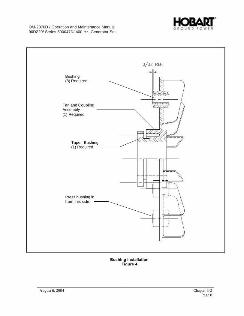
OM-2076D / Operation and Maintenance Manual90DZ20/ Series 500047D/ 400 Hz. Generator Set
August 6, 2004 Chapter 3-2Page 8
Bushing(8) Required
Fan and CouplingAssembly(1) Required
Taper Bushing(1) Required
Press bushing infrom this side.
Bushing InstallationFigure 4

OM-2076D / Operation and Maintenance Manual90DZ20/ Series 500047D/ 400 Hz. Generator Set
August 6, 2004 Chapter 3-2Page 9
Assembly ProcedureFigure 5
Measure from mounting face to adapter ring.Figure 6

OM-2076D / Operation and Maintenance Manual90DZ20/ Series 500047D/ 400 Hz. Generator Set
August 6, 2004 Chapter 3-2Page 10
Measuring From Mounting Face To BushingFigure 7
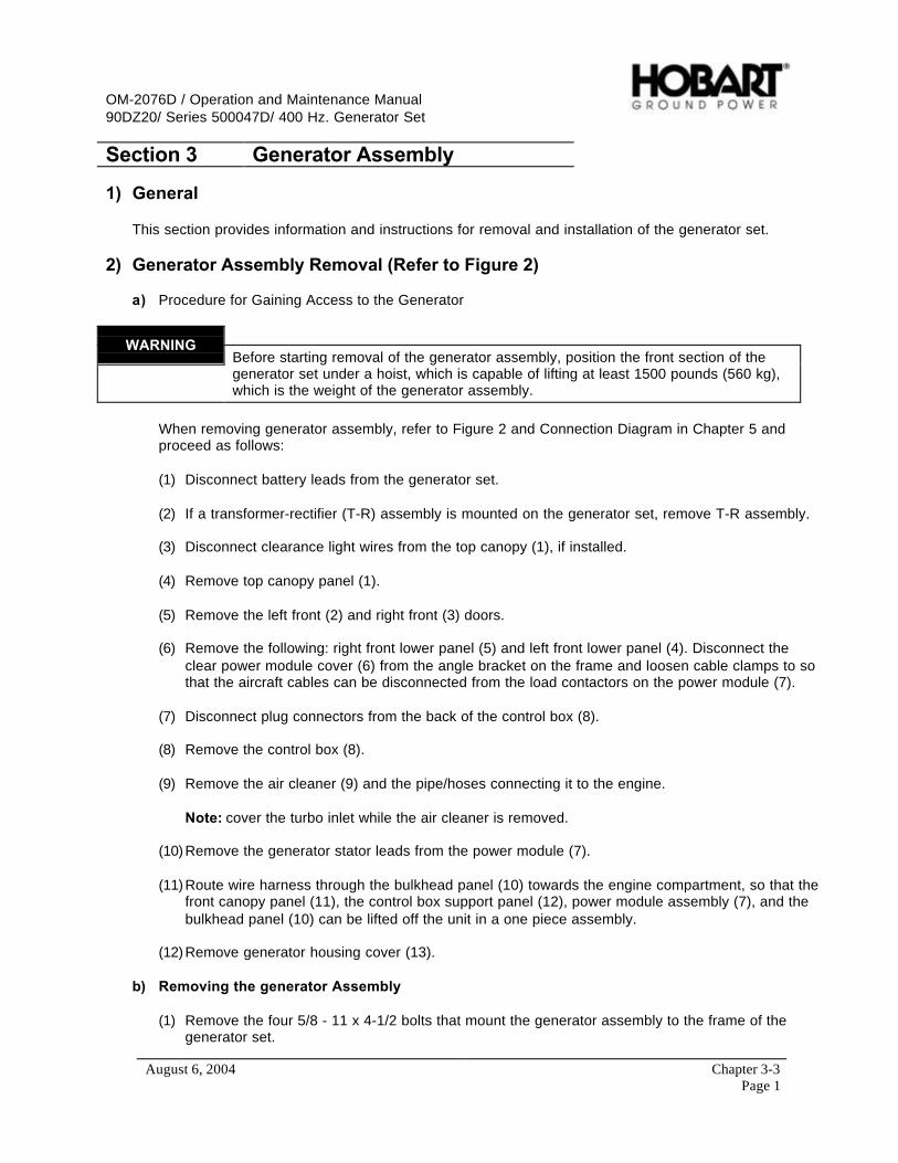
OM-2076D / Operation and Maintenance Manual90DZ20/ Series 500047D/ 400 Hz. Generator Set
August 6, 2004 Chapter 3-3Page 1
Section 3 Generator Assembly
1) General
This section provides information and instructions for removal and installation of the generator set.
2) Generator Assembly Removal (Refer to Figure 2)
a) Procedure for Gaining Access to the Generator
WARNINGBefore starting removal of the generator assembly, position the front section of thegenerator set under a hoist, which is capable of lifting at least 1500 pounds (560 kg),which is the weight of the generator assembly.
When removing generator assembly, refer to Figure 2 and Connection Diagram in Chapter 5 andproceed as follows:
(1) Disconnect battery leads from the generator set.
(2) If a transformer-rectifier (T-R) assembly is mounted on the generator set, remove T-R assembly.
(3) Disconnect clearance light wires from the top canopy (1), if installed.
(4) Remove top canopy panel (1).
(5) Remove the left front (2) and right front (3) doors.
(6) Remove the following: right front lower panel (5) and left front lower panel (4). Disconnect theclear power module cover (6) from the angle bracket on the frame and loosen cable clamps to sothat the aircraft cables can be disconnected from the load contactors on the power module (7).
(7) Disconnect plug connectors from the back of the control box (8).
(8) Remove the control box (8).
(9) Remove the air cleaner (9) and the pipe/hoses connecting it to the engine.
Note: cover the turbo inlet while the air cleaner is removed.
(10) Remove the generator stator leads from the power module (7).
(11) Route wire harness through the bulkhead panel (10) towards the engine compartment, so that thefront canopy panel (11), the control box support panel (12), power module assembly (7), and thebulkhead panel (10) can be lifted off the unit in a one piece assembly.
(12) Remove generator housing cover (13).
b) Removing the generator Assembly
(1) Remove the four 5/8 - 11 x 4-1/2 bolts that mount the generator assembly to the frame of thegenerator set.

OM-2076D / Operation and Maintenance Manual90DZ20/ Series 500047D/ 400 Hz. Generator Set
August 6, 2004 Chapter 3-3Page 2
(2) Support the engine at the flywheel housing with wooden blocks, or second hoist if available.
(3) Using the hoist, support the generator assembly. For lifting convenience, a M12-1.75 threadedhole is drilled in the top of the generator housing. Insert a M12-1.75 eyebolt in the hole and attachthe hoist chain to the eyebolt as shown in Figure 1.
(4) Remove the M12-1.75 bolts generator-to-flywheel coupling bolts.
(5) Detach the generator housing from the engine. Do this by removing the six M10 - 1.5 x 35 metricbolts.
(6) Carefully lift and separate the generator from the engine.
Hoist
Lifting Eye
Generator
Generator Lifting ArrangementFigure 1

OM-2076D / Operation and Maintenance Manual90DZ20/ Series 500047D/ 400 Hz. Generator Set
August 6, 2004 Chapter 3-3Page 3
1
2
3
5
4
6
8
9
10
11
12137
1. Canopy Top Assembly2. Right Front Door3. Control Box Door (Left Front Door)4. Left Front Lower Panel5. Right Front Lower Panel6. Power Module Cover7. Power Module Assembly
8. Control Box Assembly9. Air Filter Assembly10. Bulkhead Panel11. Front Canopy Panel12. Control Box Support13. Generator Cover
Component Removal Required for Access to GeneratorFigure 2

OM-2076D / Operation and Maintenance Manual90DZ20/ Series 500047D/ 400 Hz. Generator Set
August 6, 2004 Chapter 3-3Page 4
3) Generator Assembly Installation
Installation of a generator assembly is essentially a reversal of the procedure for removal of the generatorassembly: the re-mounting of the generator assembly to the frame of the generator set, and theremounting of the assemblies that were removed to gain access to the generator assembly. To install thegenerator assembly, refer to Connection Diagram, and proceed as follows:
a) Remounting the Generator Assembly
(1) Support engine at flywheel housing with wooden blocks, or second hoist if available.
(2) Using the hoist, support the generator assembly and lower it carefully and slowly into position forattachment to the engine.
(3) While still supporting the generator assembly with the hoist, attach the generator housing to theengine, using the six M10 - 1.5 x 35 metric bolts. Torque bolts to 30 ft-lb (41 N-m).
(4) Attach the generator to the flywheel coupling, using the eight M12-1.75 bolts. Torque bolts to 85ft-lb (115 N-m).
(5) Mount the generator housing to the frame of the generator set, using the four 5/8 - 11 x 4-1/2bolts.
(6) Install the generator wrapper on the generator assembly, using 1/4 - 20 x 1/2 tap-tite screws.
b) Remounting the previously removed assemblies
(1) Remount the remaining pieces of the unit in reverse order of disassembly procedure.

OM-2076D / Operation and Maintenance Manual90DZ20/ Series 500047D/ 400 Hz. Generator Set
August 6, 2004 Chapter 4-1Page 1
Chapter 4 Illustrated Parts List
Section 1 Introduction
1) General
The Illustrated Parts List identifies, describes, and illustrates main assemblies, subassemblies, and detailparts of an Engine-Generator Set manufactured by ITW GSE Group, Hobart Ground Power.
2) Purpose
The purpose of this list is to provide parts identification and descriptive information to maintenance andprovisioning personnel for use in provisioning, requisitioning, purchasing, storing, and issuing of spareparts.
3) Arrangement
Chapter 4 is arranged as follows:
Section 1 - IntroductionSection 2 - Manufacturer’s CodesSection 3 - Parts ListSection 4 - Numerical index
4) Explanation of Parts List
a) Contents
The parts list contains a breakdown of the equipment into assemblies, subassemblies, and detailparts. All parts of the equipment are listed except:
(1) Standard hardware items (attaching parts) such as nuts, screws, washers, etc., which areavailable commercially.
(2) Bulk items such as wire, cable, sleeving, tubing, etc., which are also commercially available.
(3) Permanently attached parts, which lose their identity by being welded, soldered, riveted, etc., toother parts, weldments, or assemblies.
b) Parts List Form
This form is divided into six columns. Beginning at the left side of the form and proceeding to theright, columns are identified as follows:
(1) FIGURE-ITEM NO. Column
This column lists the figure number of the illustration applicable to a particular parts list and alsoidentifies each part in the list by an item number. These item numbers also appear on theillustration. Each item number on an illustration is connected to the part to which it pertains by aleader line. Thus the figure and item numbering system ties the parts lists to the illustrations and

OM-2076D / Operation and Maintenance Manual90DZ20/ Series 500047D/ 400 Hz. Generator Set
August 6, 2004 Chapter 4-1Page 2
vice-versa. The figure and index numbers are also used in the numerical index to assist the userin finding the illustration of a part when the part number is known.
(2) FACTORY PART NUMBER Column
All part numbers appearing in this column are Hobart numbers. In all instances where the part isa purchased item, the vendor’s identifying five-digit code and his part number will appear in the“NOMENCLATURE” column. Vendor parts, which are modified by Hobart, will be identified assuch in the “NOMENCLATURE” column. In case Hobart does not have an identifying partnumber for a purchased part, the “FACTORY PART NUMBER” column will reflect “No Number”and the vendor’s number will be shown in the “NOMENCLATURE” column. Parts manufacturedby Hobart will reflect no vendor or part number in the “NOMENCLATURE” column.
(3) NOMENCLATURE Column
The item-identifying name appears in this column. The indenture method is used to indicate itemrelationship. Thus, components of an assembly are listed directly below the assembly andindented one space. Vendor codes and part numbers for purchased parts are also listed in thiscolumn when applicable. Hobart modification to vendor items is also noted in this column.
(4) EFF (Effective) Column
This column is used to indicate the applicability of parts to different models of equipment. Whenmore than one model of equipment is covered by a parts list, there are some parts that are usedon only one model. This column is used for insertion of a code letter A, B, etc., to indicate theseparts and to identify the particular model they are used on. Since this manual covers more thanone generator set specification, this column is used as follows:
Parts coded “A” are usable on Part Number 500047D-001 only.Parts coded “B” are usable on Part Number 500047D-002 only.Parts coded “C” are usable on Part Number 500047D-003 only.Parts coded “D” are usable on Part Number 500047D-004 only.Parts coded “E” are usable on Part Number 500047D-005 only.Parts coded “F” are usable on Part Number 500047D-006 only.Parts coded “G” are usable on Part Number 500047D-007 only.Parts coded “H” are usable on Part Number 500047D-008 only.Parts coded “J” are usable on Part Number 500047D-009 only (Special Configuration).
(5) UNITS PER ASSEMBLY Column
This column indicates the quantity of parts required for an assembly or subassembly in which thepart appears. This column does not necessarily reflect the total used in the complete end item.
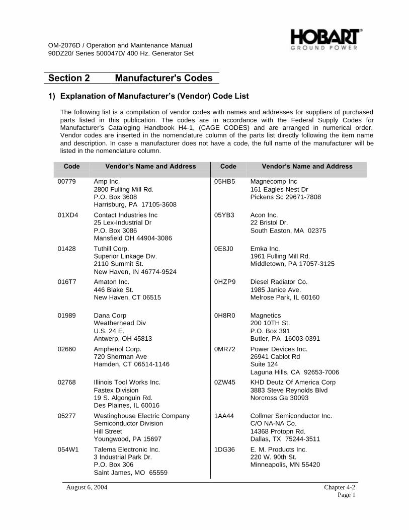
OM-2076D / Operation and Maintenance Manual90DZ20/ Series 500047D/ 400 Hz. Generator Set
August 6, 2004 Chapter 4-2Page 1
Section 2 Manufacturer's Codes
1) Explanation of Manufacturer’s (Vendor) Code List
The following list is a compilation of vendor codes with names and addresses for suppliers of purchasedparts listed in this publication. The codes are in accordance with the Federal Supply Codes forManufacturer’s Cataloging Handbook H4-1, (CAGE CODES) and are arranged in numerical order.Vendor codes are inserted in the nomenclature column of the parts list directly following the item nameand description. In case a manufacturer does not have a code, the full name of the manufacturer will belisted in the nomenclature column.
Code Vendor’s Name and Address Code Vendor’s Name and Address
00779 Amp Inc.2800 Fulling Mill Rd.P.O. Box 3608Harrisburg, PA 17105-3608
05HB5 Magnecomp Inc161 Eagles Nest DrPickens Sc 29671-7808
01XD4 Contact Industries Inc25 Lex-Industrial DrP.O. Box 3086Mansfield OH 44904-3086
05YB3 Acon Inc.22 Bristol Dr.South Easton, MA 02375
01428 Tuthill Corp.Superior Linkage Div.2110 Summit St.New Haven, IN 46774-9524
0E8J0 Emka Inc.1961 Fulling Mill Rd.Middletown, PA 17057-3125
016T7 Amaton Inc.446 Blake St.New Haven, CT 06515
0HZP9 Diesel Radiator Co.1985 Janice Ave.Melrose Park, IL 60160
01989 Dana CorpWeatherhead DivU.S. 24 E.Antwerp, OH 45813
0H8R0 Magnetics200 10TH St.P.O. Box 391Butler, PA 16003-0391
02660 Amphenol Corp.720 Sherman AveHamden, CT 06514-1146
0MR72 Power Devices Inc.26941 Cablot RdSuite 124Laguna Hills, CA 92653-7006
02768 Illinois Tool Works Inc.Fastex Division19 S. Algonguin Rd.Des Plaines, IL 60016
0ZW45 KHD Deutz Of America Corp3883 Steve Reynolds BlvdNorcross Ga 30093
05277 Westinghouse Electric CompanySemiconductor DivisionHill StreetYoungwood, PA 15697
1AA44 Collmer Semiconductor Inc.C/O NA-NA Co.14368 Protopn Rd.Dallas, TX 75244-3511
054W1 Talema Electronic Inc.3 Industrial Park Dr.P.O. Box 306Saint James, MO 65559
1DG36 E. M. Products Inc.220 W. 90th St.Minneapolis, MN 55420

OM-2076D / Operation and Maintenance Manual90DZ20/ Series 500047D/ 400 Hz. Generator Set
August 6, 2004 Chapter 4-2Page 2
Code Vendor’s Name and Address Code Vendor’s Name and Address
1E045 Austin Hardware and Supply Co.10220 E. 65TH St.P.O. Box 9550Kansas City, MO 64133-5205
14552 Microsemi Corp2830 S. Fairview St.Santa Ana, CA 92704-5948
1E222 Furnas Electric Co.Richmond, VA 23200
14799 Square D Co.Chicago Assembly Plant9522 W. WinonaSchiller Park, IL 60176-1025
1FQ83 Newark Electronics Div3033 Kettering BlvdDayton OH 45439
14604 Elmwood Sensors, Inc.Subsidary Fasco Ind.1655 Elmwood AvenueCranston, RI 02907
1PAM0 DAVCO Manfacturing1600 Woodland Dr.Saline MI 48176
14892 Bendix Corp.The Brake And Steering Div.401 N Bendix DrSouth Bend IN 46634
1SPJ9 Hobart Ground Power1177 Trade Road EastTroy, OH 45373
16238 Lord Mfg. Co. Inc.Sterling RoadSouth Lancaster, Mass 01561
1W134 Eaton Corp.4201 N. 27TH Ave.Milwaukee, WI 53216-1807
16476 Datcon Instrument Co.P.O. Box 128East Petersburg, PA 17520
1Y498 F B Wright100 E Wilson Bridge RdColumbus Oh 43085-2334
17284 Mercury Metal Company1201 S. Mercury Dr.Schaumburg, IL 60193
12662 Peterson Mfg Co.4200 E 135th StGrandview MO 64030-2821
18265 Donaldson Co. Inc.1400 W. 94th St.P.O. Box 1299Minneaplis, MN 55440-1299
12687 Trilectron Industries11001 U.S. Hwy. 41 NorthPalmetto, Florida 34221
2B664 All-Phase Electric Supply Co1620 W Main StP.O. Box 149Springfield OH 45501-0149
13445 Cole-Herse20 Old Colony Ave.Boston, MA 02127
2B928 Barber Colman Co.Pasadena, TX 77501
13902 Smith Valve Corp.1 Apple HL Suite 316Natick, MA 01760-2072
2N562 Power Transmission Sales Inc.351 WashingtonP.O. Box 229Chagrin Falls, OH 44022-4446
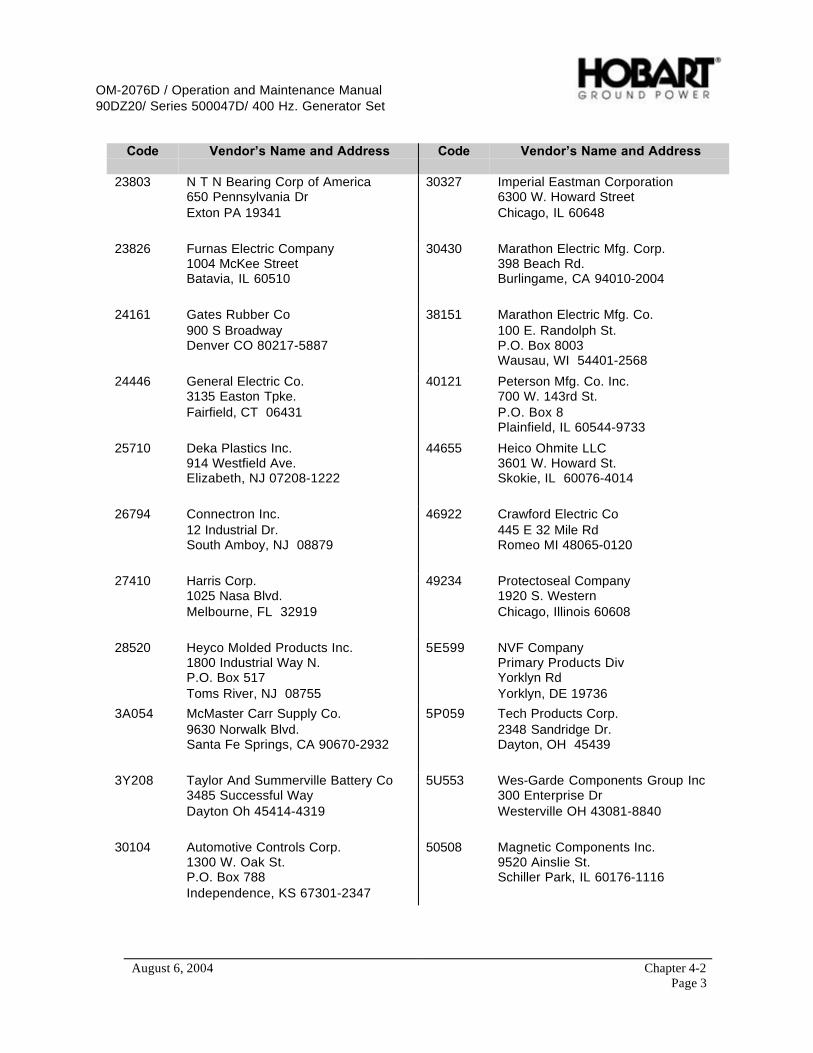
OM-2076D / Operation and Maintenance Manual90DZ20/ Series 500047D/ 400 Hz. Generator Set
August 6, 2004 Chapter 4-2Page 3
Code Vendor’s Name and Address Code Vendor’s Name and Address
23803 N T N Bearing Corp of America650 Pennsylvania DrExton PA 19341
30327 Imperial Eastman Corporation6300 W. Howard StreetChicago, IL 60648
23826 Furnas Electric Company1004 McKee StreetBatavia, IL 60510
30430 Marathon Electric Mfg. Corp.398 Beach Rd.Burlingame, CA 94010-2004
24161 Gates Rubber Co900 S BroadwayDenver CO 80217-5887
38151 Marathon Electric Mfg. Co.100 E. Randolph St.P.O. Box 8003Wausau, WI 54401-2568
24446 General Electric Co.3135 Easton Tpke.Fairfield, CT 06431
40121 Peterson Mfg. Co. Inc.700 W. 143rd St.P.O. Box 8Plainfield, IL 60544-9733
25710 Deka Plastics Inc.914 Westfield Ave.Elizabeth, NJ 07208-1222
44655 Heico Ohmite LLC3601 W. Howard St.Skokie, IL 60076-4014
26794 Connectron Inc.12 Industrial Dr.South Amboy, NJ 08879
46922 Crawford Electric Co445 E 32 Mile RdRomeo MI 48065-0120
27410 Harris Corp.1025 Nasa Blvd.Melbourne, FL 32919
49234 Protectoseal Company1920 S. WesternChicago, Illinois 60608
28520 Heyco Molded Products Inc.1800 Industrial Way N.P.O. Box 517Toms River, NJ 08755
5E599 NVF CompanyPrimary Products DivYorklyn RdYorklyn, DE 19736
3A054 McMaster Carr Supply Co.9630 Norwalk Blvd.Santa Fe Springs, CA 90670-2932
5P059 Tech Products Corp.2348 Sandridge Dr.Dayton, OH 45439
3Y208 Taylor And Summerville Battery Co3485 Successful WayDayton Oh 45414-4319
5U553 Wes-Garde Components Group Inc300 Enterprise DrWesterville OH 43081-8840
30104 Automotive Controls Corp.1300 W. Oak St.P.O. Box 788Independence, KS 67301-2347
50508 Magnetic Components Inc.9520 Ainslie St.Schiller Park, IL 60176-1116
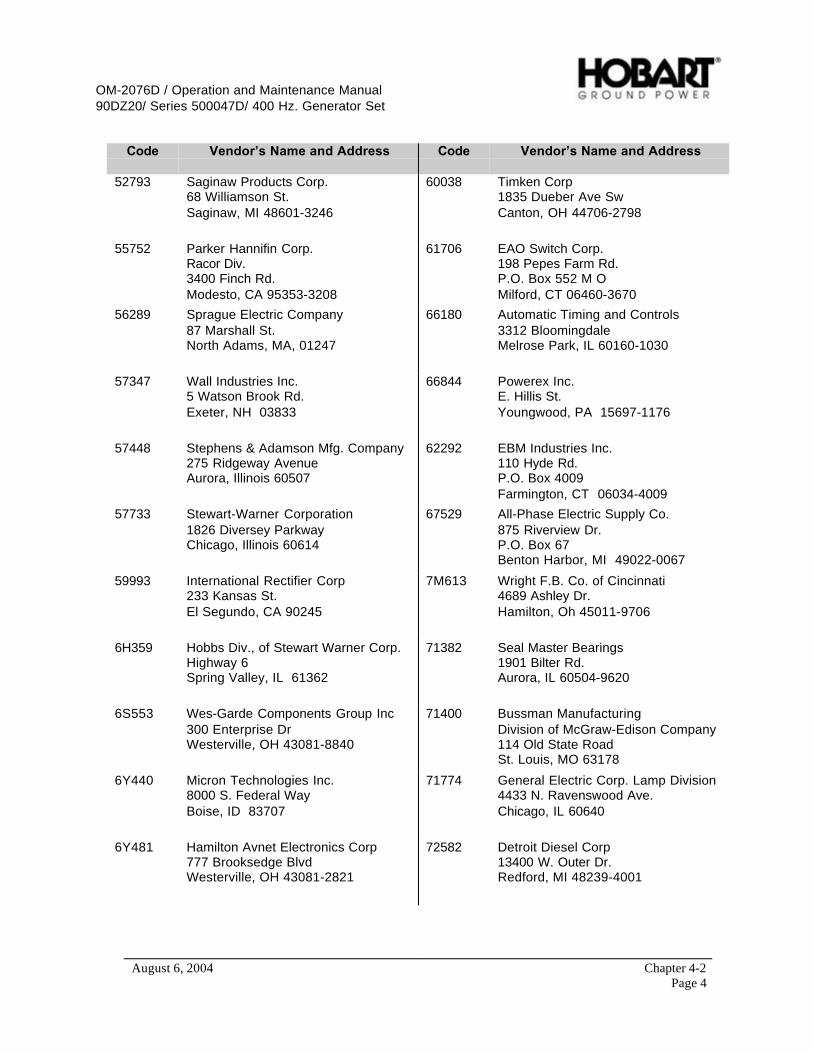
OM-2076D / Operation and Maintenance Manual90DZ20/ Series 500047D/ 400 Hz. Generator Set
August 6, 2004 Chapter 4-2Page 4
Code Vendor’s Name and Address Code Vendor’s Name and Address
52793 Saginaw Products Corp.68 Williamson St.Saginaw, MI 48601-3246
60038 Timken Corp1835 Dueber Ave SwCanton, OH 44706-2798
55752 Parker Hannifin Corp.Racor Div.3400 Finch Rd.Modesto, CA 95353-3208
61706 EAO Switch Corp.198 Pepes Farm Rd.P.O. Box 552 M OMilford, CT 06460-3670
56289 Sprague Electric Company87 Marshall St.North Adams, MA, 01247
66180 Automatic Timing and Controls3312 BloomingdaleMelrose Park, IL 60160-1030
57347 Wall Industries Inc.5 Watson Brook Rd.Exeter, NH 03833
66844 Powerex Inc.E. Hillis St.Youngwood, PA 15697-1176
57448 Stephens & Adamson Mfg. Company275 Ridgeway AvenueAurora, Illinois 60507
62292 EBM Industries Inc.110 Hyde Rd.P.O. Box 4009Farmington, CT 06034-4009
57733 Stewart-Warner Corporation1826 Diversey ParkwayChicago, Illinois 60614
67529 All-Phase Electric Supply Co.875 Riverview Dr.P.O. Box 67Benton Harbor, MI 49022-0067
59993 International Rectifier Corp233 Kansas St.El Segundo, CA 90245
7M613 Wright F.B. Co. of Cincinnati4689 Ashley Dr.Hamilton, Oh 45011-9706
6H359 Hobbs Div., of Stewart Warner Corp.Highway 6Spring Valley, IL 61362
71382 Seal Master Bearings1901 Bilter Rd.Aurora, IL 60504-9620
6S553 Wes-Garde Components Group Inc300 Enterprise DrWesterville, OH 43081-8840
71400 Bussman ManufacturingDivision of McGraw-Edison Company114 Old State RoadSt. Louis, MO 63178
6Y440 Micron Technologies Inc.8000 S. Federal WayBoise, ID 83707
71774 General Electric Corp. Lamp Division4433 N. Ravenswood Ave.Chicago, IL 60640
6Y481 Hamilton Avnet Electronics Corp777 Brooksedge BlvdWesterville, OH 43081-2821
72582 Detroit Diesel Corp13400 W. Outer Dr.Redford, MI 48239-4001

OM-2076D / Operation and Maintenance Manual90DZ20/ Series 500047D/ 400 Hz. Generator Set
August 6, 2004 Chapter 4-2Page 5
Code Vendor’s Name and Address Code Vendor’s Name and Address
72619 Amperex Electronic Corp.Dialight Division203 Harrison PlaceBrooklyn, NY 11237
8A334 Cummins Interstate Power Inc4000 Lyman DrHilliard OH 43026
74829 Ilsco Corp.4730 Madison Rd.Cincinnati, OH 45227-1426
8T246 Whitesell RO & Associates, Inc.4133 S. Dixie Ave.Dayton, OH 45439
77166 Pass and SeymourP.O. Box 4822Syracuse, NY 13221
81074 Holub Industries, Inc.413 DeKalb AvenueSycamore, Illinois 60178
74542 Hoyt Electrical InstrumentsP.O. Box 8798Penacook, NH 03303
81703 Mulberry Metal Products Inc.2199 Stanley TerraceUnion , NJ 07083
74545 Hubbell Harvey Inc.584 Derby Milford Rd.Orange, CT 06477
82866 Research Products Corp.1015 E. Washington Ave.Madison, WI 53701
75418 Kysor Industrial Corporation1100 W. Wright StreetCadillac, Michigan 49601
83330 Dialight Corp.1913 Atlantic Ave.Manasquan, NJ 08736-1005
74559 Electrical EnclosuresDiv Of Hoover Systems12118 Corporate DrDallas TX 75228
86797 Rogan Corp3455 Woodhead Dr.Northbrook, IL 60062-1812
77342 Potter and Brumfield Inc200 S. Richland Creek Dr.Princeton, IN 47671-0001
90201 Emhart Ind., Inc.Mallory Capacitor Co.4760 Kentucky Ave.Indianapolis, IN 46206
78377 Superior Carbon Products IncCleveland OH 44100
91637 Dale Electronics Inc.1122 23RD St.Columbas, NE 68601-3647
78388 Synchro-Start Products IncSub of Knowles Electronics Inc6250 W Howard StNiles, Il 60714
91929 Honeywell Inc.Microswitch Div.11 W. Spring St.Freeport, IL 61032
79497 Western Rubber Co.620 E. DouglasGoshen, IN 46526-4035
94222 Southco Inc.210 N. Brinton Lake Rd.Concordville, PA 19331

OM-2076D / Operation and Maintenance Manual90DZ20/ Series 500047D/ 400 Hz. Generator Set
August 6, 2004 Chapter 4-2Page 6
Code Vendor’s Name and Address Code Vendor’s Name and Address
97520 Basler Electric CompanyRoute 143P.O. Box 269Highland, IL 62249
D0024 Semikron InternationalSigmundstrasse 200P.O. Box 820251Nuerengerg, Germany 90253
E0615 Kraus and Naimer42 Miramar AvenueP.O. Box 15-009Wellington, New Zealand
S7023 Bossard LTD FastenersSteinhauserstrasse 70ZugSwitzerland, CH-6300
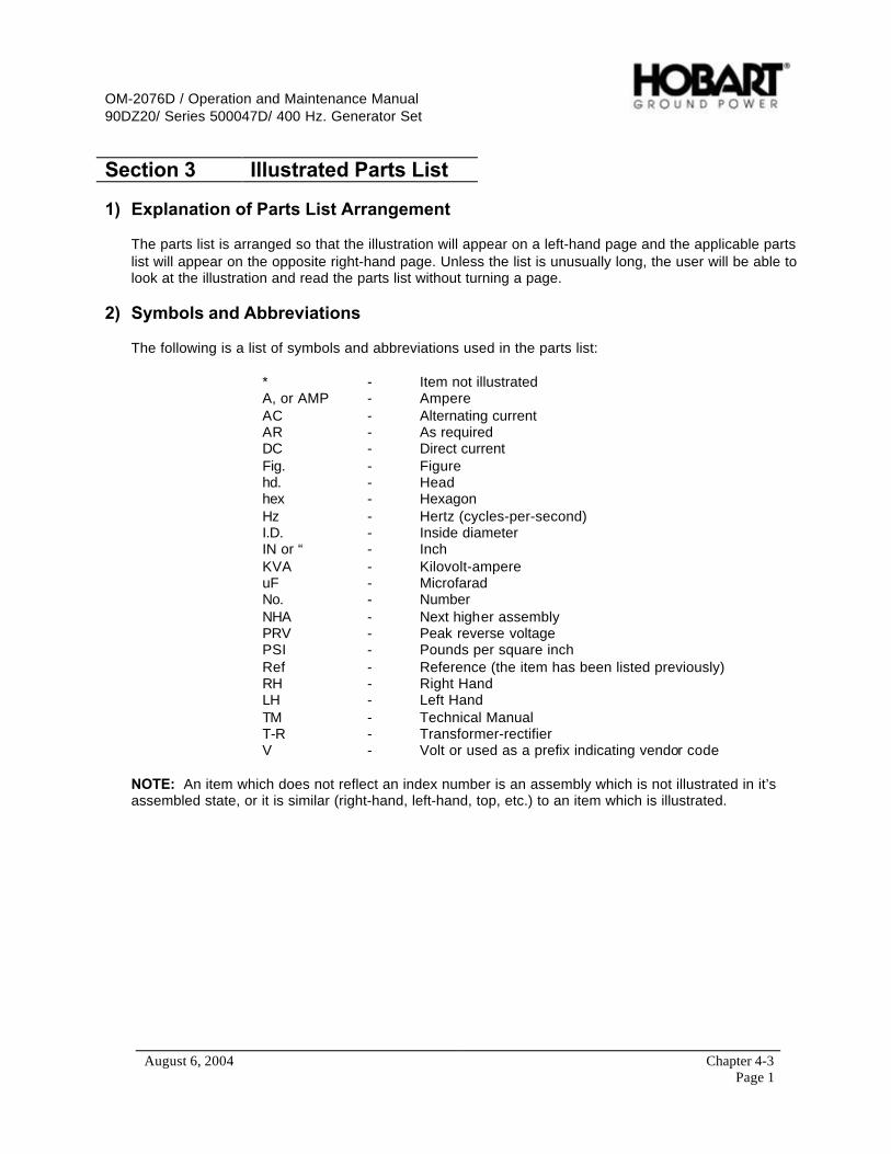
OM-2076D / Operation and Maintenance Manual90DZ20/ Series 500047D/ 400 Hz. Generator Set
August 6, 2004 Chapter 4-3Page 1
Section 3 Illustrated Parts List
1) Explanation of Parts List Arrangement
The parts list is arranged so that the illustration will appear on a left-hand page and the applicable partslist will appear on the opposite right-hand page. Unless the list is unusually long, the user will be able tolook at the illustration and read the parts list without turning a page.
2) Symbols and Abbreviations
The following is a list of symbols and abbreviations used in the parts list:
* - Item not illustratedA, or AMP - AmpereAC - Alternating currentAR - As requiredDC - Direct currentFig. - Figurehd. - Headhex - HexagonHz - Hertz (cycles-per-second)I.D. - Inside diameterIN or “ - InchKVA - Kilovolt-ampereuF - MicrofaradNo. - NumberNHA - Next higher assemblyPRV - Peak reverse voltagePSI - Pounds per square inchRef - Reference (the item has been listed previously)RH - Right HandLH - Left HandTM - Technical ManualT-R - Transformer-rectifierV - Volt or used as a prefix indicating vendor code
NOTE: An item which does not reflect an index number is an assembly which is not illustrated in it’sassembled state, or it is similar (right-hand, left-hand, top, etc.) to an item which is illustrated.
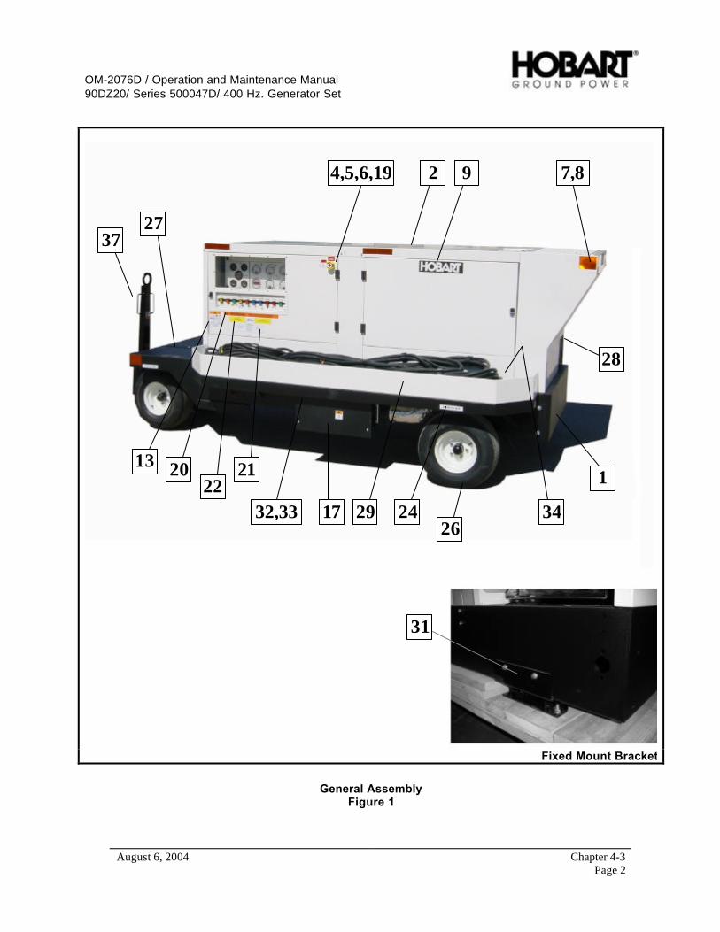
OM-2076D / Operation and Maintenance Manual90DZ20/ Series 500047D/ 400 Hz. Generator Set
August 6, 2004 Chapter 4-3Page 2
4,5,6,19 2 9 7,8
28
34
1
29 2432,33 17
2122
2013
27
26
37
31
Fixed Mount Bracket
General AssemblyFigure 1

OM-2076D / Operation and Maintenance Manual90DZ20/ Series 500047D/ 400 Hz. Generator Set
August 6, 2004 Chapter 4-3Page 3
FIGUREITEM NO.
FACTORYPART NO. NOMENCLATURE EFF
UNIT PERASSY.
1- 1 Frame Assembly (See Figure 2) Ref.2 Canopy Assembly (See Figure 3) Ref.
* 3 Generator Set Internal Components (See Fig. 4) Ref.4 285125 Guard, Mushroom Button (V14799 # K564M) 15 288300 Plate, Legend, Emergency Stop 16 77A1157 Switch, Maintained, Push-Pull (V14799 #KR-9R-H6) 17 408665-1 Reflector. Red (V12662 #B491) 88 408665-2 Reflector, Amber (V12662 #B491A) 249 4025987 Label, Hobart 2
* 10 289177-2 Instructions, Operating 1* 11 287696 Label, Hearing Protection 1* 12 76B1148 Label, Diesel Fuel 1
13 287459 Label, General 1* 14 287460 Label, High Voltage 1* 15 287461 Label, Fuel 1* 16 287462 Label, Radiator 1
17 287463 Label, Hot Muffler 2* 18 287464 Label, Moving Parts 2
19 287466 Label, Emergency Stop 120 282658 Label, Warning Clearance 121 288866 Label, Support Center 122 288862 Label, Caution, Engine Speed 1
* 23 287465 Label, Warning Drawbar A,C,E,G,J 224 287571 Label, Tire Pressure A,C,E,G,J 4
* 25 283714-2 Label, kVA Rating 226 285418 Wheel, Ay. 20.5 x 8.00 – 10 A,C,E,G,J 427 282667 Bracket, 5th Wheel Assembly A,C,E,G,J 1
282727 …Plate, Cover A,C,E,G,J 1* 280763 …Plate, Bearing A,C,E,G,J 1* 408781-1 …Pin, Spring A,C,E,G,J 2
28 288697 Tray, Cable, Right A,C,E,G,J 1* 288698 …Cover, DC Cable A,C,E,G,J 1* 288694 …Panel, Cable Guide A,C,E,G,J 1
29 288696 Tray, Cable, Left A,C,E,G,J 1* 288695 …Cover, AC Cable A,C,E,G,J 1* 288695 …Cover, AC Cable E,F,G,H 2* 288694 …Panel, Cable Guide A,C,E,G,J 1* 30 7J422-0 Clamp, Cable 2* Clamp, Cable (when DC is supplied) E,F,G,H 3* Clamp, Cable (with 2nd output) C,D,G,H 4
31 287808 Kit, Fixed Mount Support B,D,F,H 132 287376 Bumper, Side A,C,E,G,J 233 287377 Support, Fender A,C,E,G,J 4
* 34 288967 Shield, Heat, Tray, Cable A,C,E,G,J 135 288703 Rear, Axle A,C,E,G,J 136 287120 Front, Axle A,C,E,G,J 137 286956 Drawbar A,C,E,G,J 138 100GH121 Bracket, Mounting Clamp 1
100GH121 Bracket, Mounting Clamp (when DC is supplied) E,F,G,H 2100GH121 Bracket, Mounting Clamp (with 2nd output) C,D,G,H 3

OM-2076D / Operation and Maintenance Manual90DZ20/ Series 500047D/ 400 Hz. Generator Set
August 6, 2004 Chapter 4-3Page 4
1
2
3
4
67
8
11910
12
13
14
12
15
16
Frame AssemblyFigure 2
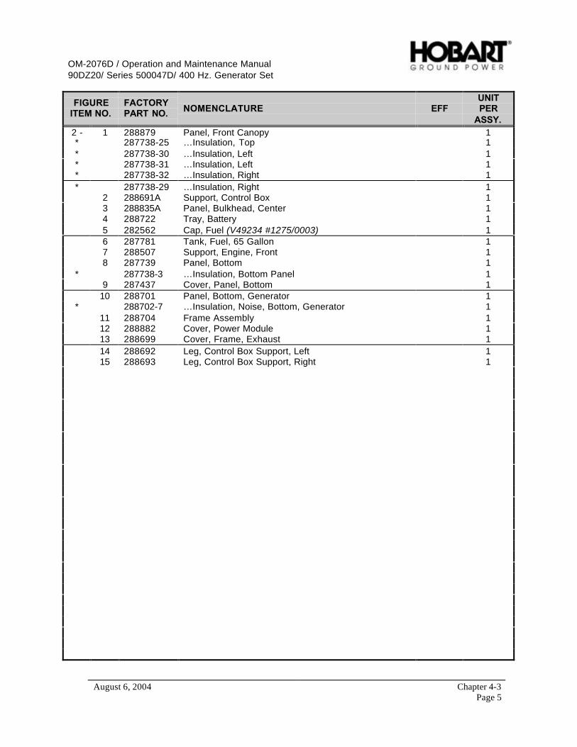
OM-2076D / Operation and Maintenance Manual90DZ20/ Series 500047D/ 400 Hz. Generator Set
August 6, 2004 Chapter 4-3Page 5
FIGUREITEM NO.
FACTORYPART NO. NOMENCLATURE EFF
UNITPER
ASSY.2 - 1 288879 Panel, Front Canopy 1* 287738-25 …Insulation, Top 1* 287738-30 …Insulation, Left 1* 287738-31 …Insulation, Left 1* 287738-32 …Insulation, Right 1* 287738-29 …Insulation, Right 1
2 288691A Support, Control Box 13 288835A Panel, Bulkhead, Center 14 288722 Tray, Battery 15 282562 Cap, Fuel (V49234 #1275/0003) 16 287781 Tank, Fuel, 65 Gallon 17 288507 Support, Engine, Front 18 287739 Panel, Bottom 1
* 287738-3 …Insulation, Bottom Panel 19 287437 Cover, Panel, Bottom 1
10 288701 Panel, Bottom, Generator 1* 288702-7 …Insulation, Noise, Bottom, Generator 1
11 288704 Frame Assembly 112 288882 Cover, Power Module 113 288699 Cover, Frame, Exhaust 114 288692 Leg, Control Box Support, Left 115 288693 Leg, Control Box Support, Right 1

OM-2076D / Operation and Maintenance Manual90DZ20/ Series 500047D/ 400 Hz. Generator Set
August 6, 2004 Chapter 4-3Page 6
1
1
1
2
3
3
4 6
7
8
9
9
9
1014
12
1113
Canopy AssemblyFigure 3
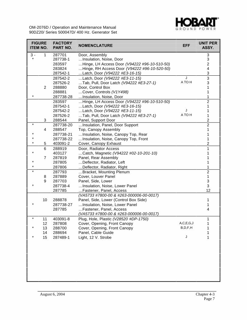
OM-2076D / Operation and Maintenance Manual90DZ20/ Series 500047D/ 400 Hz. Generator Set
August 6, 2004 Chapter 4-3Page 7
FIGUREITEM NO.
FACTORYPART NO. NOMENCLATURE EFF
UNIT PERASSY.
3 - 1 287701 Door, Assembly 3* 287738-1 …Insulation, Noise, Door 3
283597 …Hinge, LH Access Door (V94222 #96-10-510-50) 2283824 …Hinge, RH Access Door (V94222 #96-10-520-50) 4287542-1 …Latch, Door (V94222 #E3-16-15) 3287542-2 …Latch, Door (V94222 #E3-11-15) J 3287526-2 …Tab, Pull, Door Latch (V94222 #E3-27-1) A TO H 3
2 288880 Door, Control Box 1288881 …Cover, Controls (V1Y498) 1
* 287738-28 …Insulation, Noise, Door 1283597 …Hinge, LH Access Door (V94222 #96-10-510-50) 2287542-1 …Latch, Door (V94222 #E3-16-15) 1287542-2 …Latch, Door (V94222 #E3-11-15) J 1287526-2 …Tab, Pull, Door Latch (V94222 #E3-27-1) A TO H 1
3 288544 Panel, Support Door 2* 287738-20 …Insulation, Panel, Door Support 2
4 288547 Top, Canopy Assembly 1* 287738-21 …Insulation, Noise, Canopy Top, Rear 1* 287738-22 …Insulation, Noise, Canopy Top, Front 1* 5 403091-2 Cover, Canopy Exhaust 2
6 288919 Door, Radiator Access 1* 403127 …Catch, Magnetic (V94222 #02-10-201-10) 1
7 287819 Panel, Rear Assembly 1* 287805 …Deflector, Radiator, Left 1* 287806 …Deflector, Radiator, Right 1* 287793 …Bracket, Mounting Plenum 2
8 287889 Cover, Louver Panel 19 287703 Panel, Side, Lower 3
* 287738-4 …Insulation, Noise, Lower Panel 3287785 …Fastener, Panel, Access 12
(VA5733 #7800-00 & #263-000006-00-0017)10 288878 Panel, Side, Lower (Control Box Side) 1
* 287738-27 …Insulation, Noise, Lower Panel 1287785 …Fastener, Panel, Access 4
(VA5733 #7800-00 & #263-000006-00-0017)* 11 403091-8 Plug, Hole, Plastic (V28520 #DP-1750) 1
12 287808 Cover, Opening, Front Canopy A,C,E,G,J 1* 13 288700 Cover, Opening, Front Canopy B,D,F,H 1
14 288694 Panel, Cable Guide 1* 15 287489-1 Light, 12 V. Strobe J 1
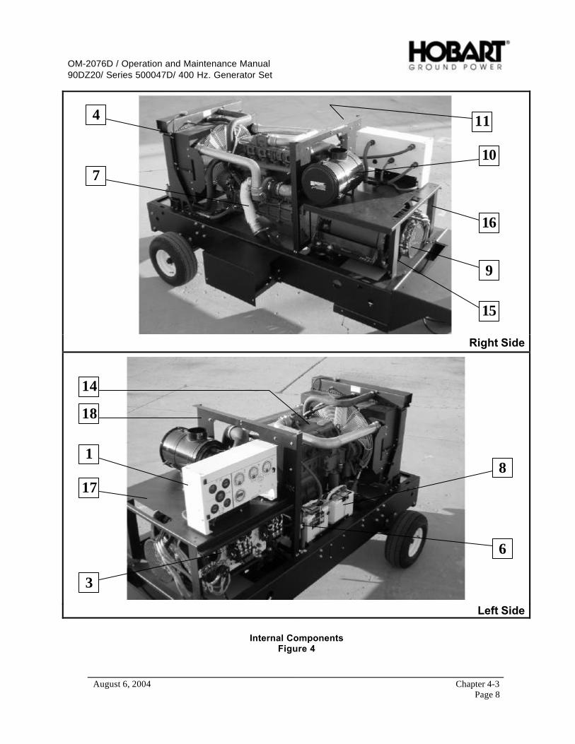
OM-2076D / Operation and Maintenance Manual90DZ20/ Series 500047D/ 400 Hz. Generator Set
August 6, 2004 Chapter 4-3Page 8
4
7
9
10
11
15
16
Right Side
1
3
8
6
14
17
18
Left Side
Internal ComponentsFigure 4
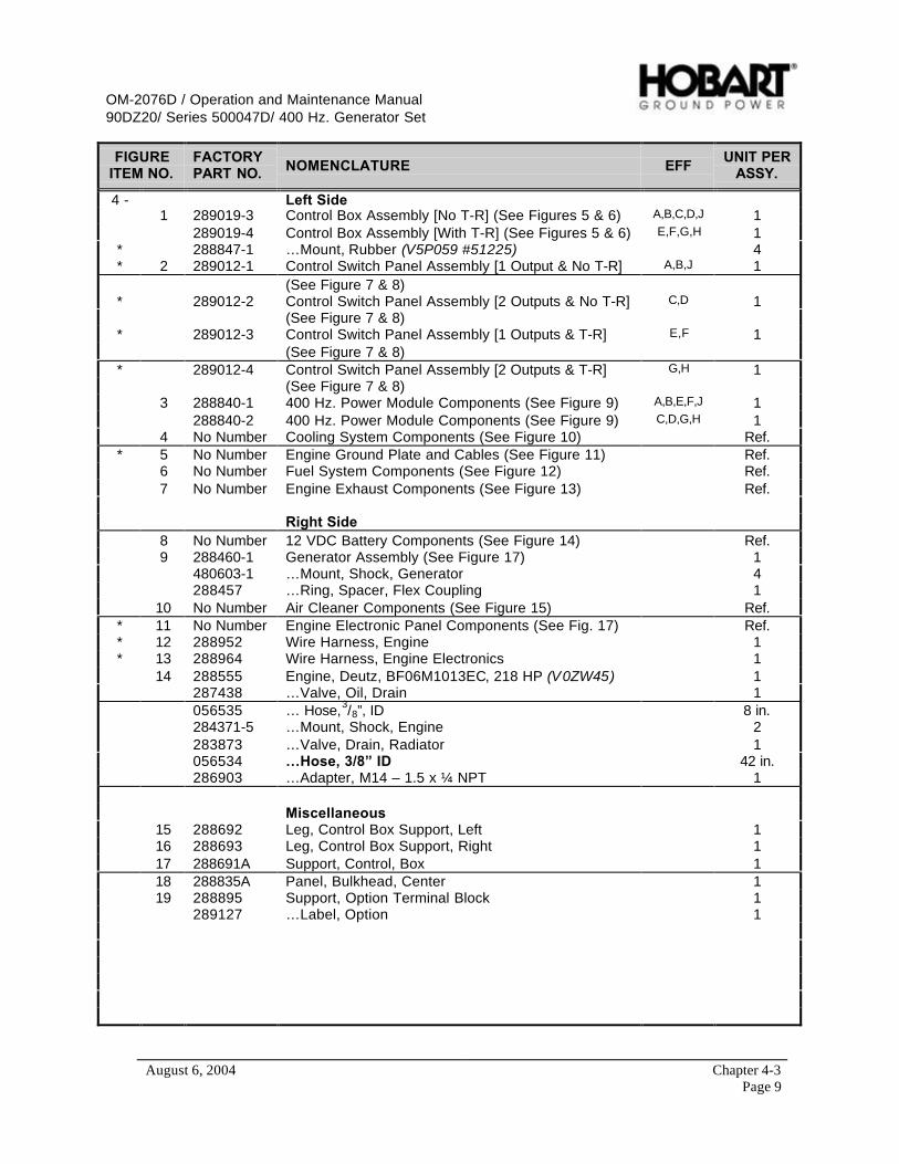
OM-2076D / Operation and Maintenance Manual90DZ20/ Series 500047D/ 400 Hz. Generator Set
August 6, 2004 Chapter 4-3Page 9
FIGUREITEM NO.
FACTORYPART NO. NOMENCLATURE EFF
UNIT PERASSY.
4 - Left Side1 289019-3 Control Box Assembly [No T-R] (See Figures 5 & 6) A,B,C,D,J 1
289019-4 Control Box Assembly [With T-R] (See Figures 5 & 6) E,F,G,H 1* 288847-1 …Mount, Rubber (V5P059 #51225) 4* 2 289012-1 Control Switch Panel Assembly [1 Output & No T-R] A,B,J 1
(See Figure 7 & 8)* 289012-2 Control Switch Panel Assembly [2 Outputs & No T-R] C,D 1
(See Figure 7 & 8)* 289012-3 Control Switch Panel Assembly [1 Outputs & T-R] E,F 1
(See Figure 7 & 8)* 289012-4 Control Switch Panel Assembly [2 Outputs & T-R] G,H 1
(See Figure 7 & 8)3 288840-1 400 Hz. Power Module Components (See Figure 9) A,B,E,F,J 1
288840-2 400 Hz. Power Module Components (See Figure 9) C,D,G,H 14 No Number Cooling System Components (See Figure 10) Ref.
* 5 No Number Engine Ground Plate and Cables (See Figure 11) Ref.6 No Number Fuel System Components (See Figure 12) Ref.7 No Number Engine Exhaust Components (See Figure 13) Ref.
Right Side8 No Number 12 VDC Battery Components (See Figure 14) Ref.9 288460-1 Generator Assembly (See Figure 17) 1
480603-1 …Mount, Shock, Generator 4288457 …Ring, Spacer, Flex Coupling 1
10 No Number Air Cleaner Components (See Figure 15) Ref.* 11 No Number Engine Electronic Panel Components (See Fig. 17) Ref.* 12 288952 Wire Harness, Engine 1* 13 288964 Wire Harness, Engine Electronics 1
14 288555 Engine, Deutz, BF06M1013EC, 218 HP (V0ZW45) 1287438 …Valve, Oil, Drain 1056535 … Hose,3/8”, ID 8 in.284371-5 …Mount, Shock, Engine 2283873 …Valve, Drain, Radiator 1056534 …Hose, 3/8” ID 42 in.286903 …Adapter, M14 – 1.5 x ¼ NPT 1
Miscellaneous15 288692 Leg, Control Box Support, Left 116 288693 Leg, Control Box Support, Right 117 288691A Support, Control, Box 118 288835A Panel, Bulkhead, Center 119 288895 Support, Option Terminal Block 1
289127 …Label, Option 1
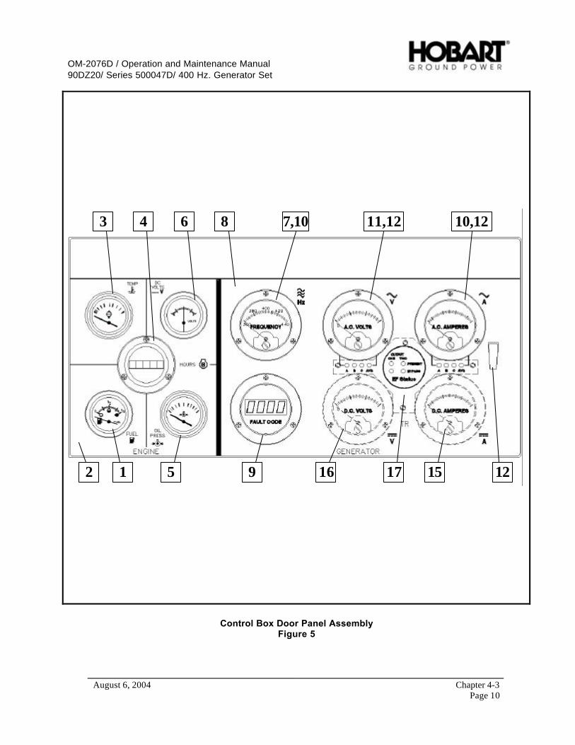
OM-2076D / Operation and Maintenance Manual90DZ20/ Series 500047D/ 400 Hz. Generator Set
August 6, 2004 Chapter 4-3Page 10
12
3 4
5
6 8 7,10 10,1211,12
129 16 1517
Control Box Door Panel AssemblyFigure 5
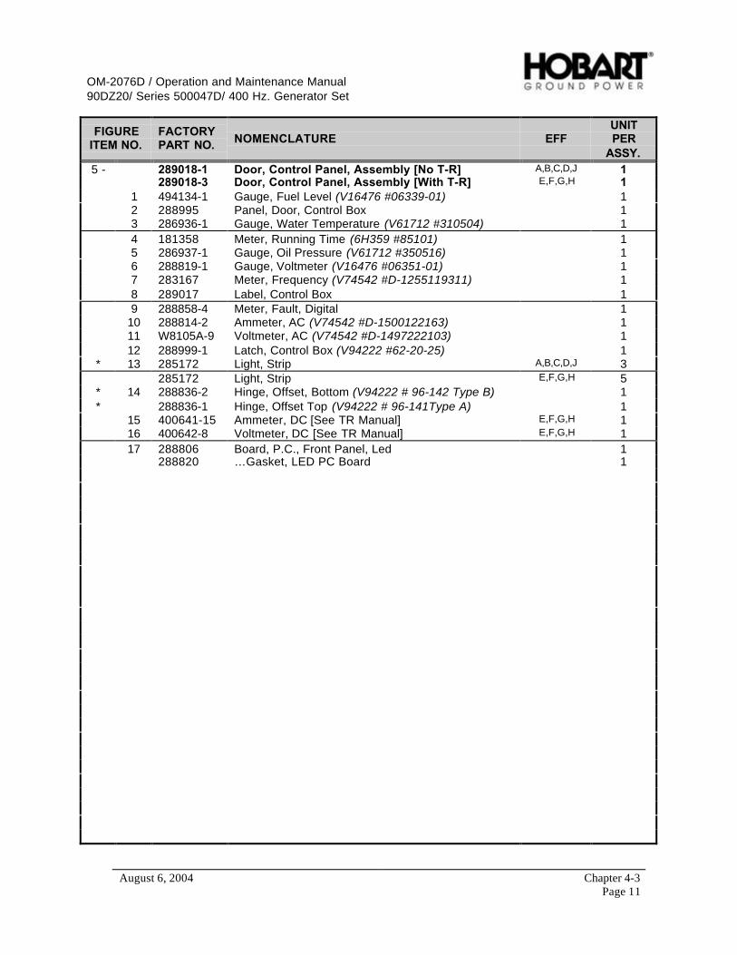
OM-2076D / Operation and Maintenance Manual90DZ20/ Series 500047D/ 400 Hz. Generator Set
August 6, 2004 Chapter 4-3Page 11
FIGUREITEM NO.
FACTORYPART NO. NOMENCLATURE EFF
UNITPER
ASSY.5 - 289018-1 Door, Control Panel, Assembly [No T-R] A,B,C,D,J 1
289018-3 Door, Control Panel, Assembly [With T-R] E,F,G,H 11 494134-1 Gauge, Fuel Level (V16476 #06339-01) 12 288995 Panel, Door, Control Box 13 286936-1 Gauge, Water Temperature (V61712 #310504) 14 181358 Meter, Running Time (6H359 #85101) 15 286937-1 Gauge, Oil Pressure (V61712 #350516) 16 288819-1 Gauge, Voltmeter (V16476 #06351-01) 17 283167 Meter, Frequency (V74542 #D-1255119311) 18 289017 Label, Control Box 19 288858-4 Meter, Fault, Digital 1
10 288814-2 Ammeter, AC (V74542 #D-1500122163) 111 W8105A-9 Voltmeter, AC (V74542 #D-1497222103) 112 288999-1 Latch, Control Box (V94222 #62-20-25) 1
* 13 285172 Light, Strip A,B,C,D,J 3285172 Light, Strip E,F,G,H 5
* 14 288836-2 Hinge, Offset, Bottom (V94222 # 96-142 Type B) 1* 288836-1 Hinge, Offset Top (V94222 # 96-141Type A) 1
15 400641-15 Ammeter, DC [See TR Manual] E,F,G,H 116 400642-8 Voltmeter, DC [See TR Manual] E,F,G,H 117 288806 Board, P.C., Front Panel, Led 1
288820 …Gasket, LED PC Board 1

OM-2076D / Operation and Maintenance Manual90DZ20/ Series 500047D/ 400 Hz. Generator Set
August 6, 2004 Chapter 4-3Page 12
4
5
1
7
6
14
811 92 31010 12
Control Box Interior ComponentsFigure 6
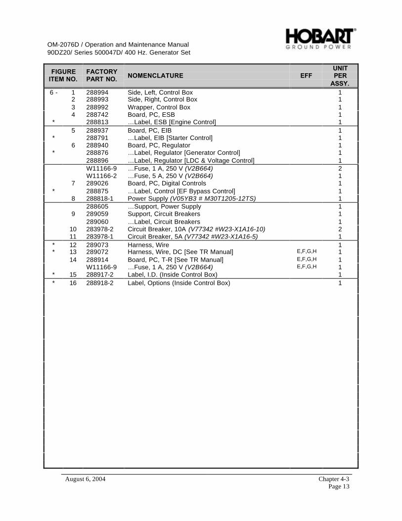
OM-2076D / Operation and Maintenance Manual90DZ20/ Series 500047D/ 400 Hz. Generator Set
August 6, 2004 Chapter 4-3Page 13
FIGUREITEM NO.
FACTORYPART NO. NOMENCLATURE EFF
UNITPER
ASSY.6 - 1 288994 Side, Left, Control Box 1
2 288993 Side, Right, Control Box 13 288992 Wrapper, Control Box 14 288742 Board, PC, ESB 1
* 288813 …Label, ESB [Engine Control] 15 288937 Board, PC, EIB 1
* 288791 …Label, EIB [Starter Control] 16 288940 Board, PC, Regulator 1
* 288876 …Label, Regulator [Generator Control] 1288896 …Label, Regulator [LDC & Voltage Control] 1W11166-9 …Fuse, 1 A, 250 V (V2B664) 2W11166-2 …Fuse, 5 A, 250 V (V2B664) 1
7 289026 Board, PC, Digital Controls 1* 288875 …Label, Control [EF Bypass Control] 1
8 288818-1 Power Supply (V05YB3 # M30T1205-12TS) 1288605 …Support, Power Supply 1
9 289059 Support, Circuit Breakers 1289060 …Label, Circuit Breakers 1
10 283978-2 Circuit Breaker, 10A (V77342 #W23-X1A16-10) 211 283978-1 Circuit Breaker, 5A (V77342 #W23-X1A16-5) 1
* 12 289073 Harness, Wire 1* 13 289072 Harness, Wire, DC [See TR Manual] E,F,G,H 1
14 288914 Board, PC, T-R [See TR Manual] E,F,G,H 1W11166-9 …Fuse, 1 A, 250 V (V2B664) E,F,G,H 1
* 15 288917-2 Label, I.D. (Inside Control Box) 1* 16 288918-2 Label, Options (Inside Control Box) 1

OM-2076D / Operation and Maintenance Manual90DZ20/ Series 500047D/ 400 Hz. Generator Set
August 6, 2004 Chapter 4-3Page 14
1 2 3 4 5 6 8 9 10
11 Item #’s 12 & 13 are bolted to item # 11.Item # 18 is located on item # 13
1514
7
Control Switch Panel ComponentsFigure 7

OM-2076D / Operation and Maintenance Manual90DZ20/ Series 500047D/ 400 Hz. Generator Set
August 6, 2004 Chapter 4-3Page 15
FIGUREITEM NO. PART NO. NOMENCLATURE EFF
UNITPER
ASSY.7 - 1 No Number Lamps Pushbutton, Yellow (See Figure 8) 1
2 No Number Pre-Heater Pushbutton, Orange (See Figure 8) 13 No Number Engine Start Pushbutton, Green (See Figure 8) 14 No Number Output # 1 Pushbutton, Yellow (See Figure 8) 15 No Number Output # 2 Pushbutton, Orange (See Figure 8) C,D,G,H 1
287038-1 Plug, Hole (when output # 2 is not used) 16 No Number DC Output Pushbutton, Blue [See T-R Manual] E,F,G,H 1
287038-1 Plug, Hole (when TR in not used) 17 No Number Starting Current Pushbutton, Blue [See T-R Manual] E,F,G,H 1
287038-1 Plug, Hole (when TR in not used) 18 No Number Engine Stop Pushbutton, Red (See Figure 8) 19 No Number Test/Reset Pushbutton, Red (See Figure 8) 1
10 No Number Meter Select Pushbutton, Green (See Figure 8) 111 288773 Panel, Switch Box 1
* 12 288772 Wrapper, Switch Box 1* 13 288771 Top, Switch Box 1
14 289004 Panel, Switch 115 289014 Label, Panel, Switch 1
* 16 W10079-3 Connector, Box Straight 1* 17 289015 Harness, Wire 1* 18 288872 Label, Fault and Command 1
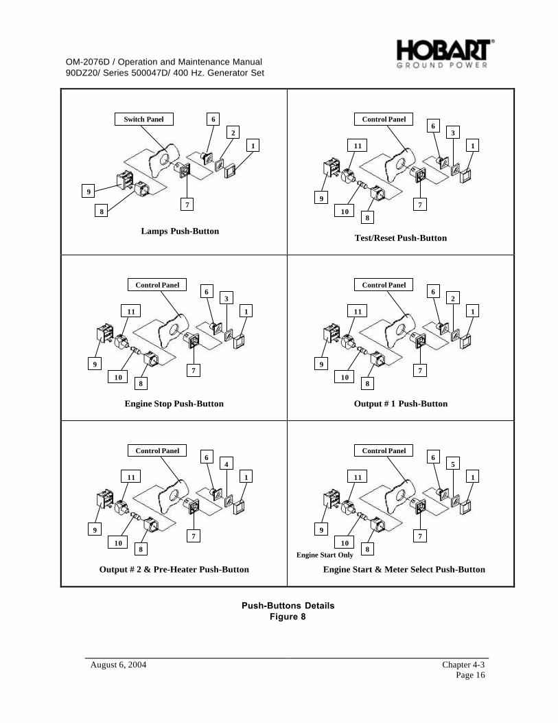
OM-2076D / Operation and Maintenance Manual90DZ20/ Series 500047D/ 400 Hz. Generator Set
August 6, 2004 Chapter 4-3Page 16
1
2
6
78
9
Lamps Push-Button
Switch Panel
Test/Reset Push-Button
Control Panel
1
36
7
810
11
9
Engine Stop Push-Button
Control Panel
1
36
7
810
11
9
Output # 1 Push-Button
Control Panel
1
26
7
810
11
9
Output # 2 & Pre-Heater Push-Button
Control Panel
1
46
7
810
11
9
Engine Start & Meter Select Push-Button
Control Panel
1
56
7
810
11
9
Engine Start Only
Push-Buttons DetailsFigure 8
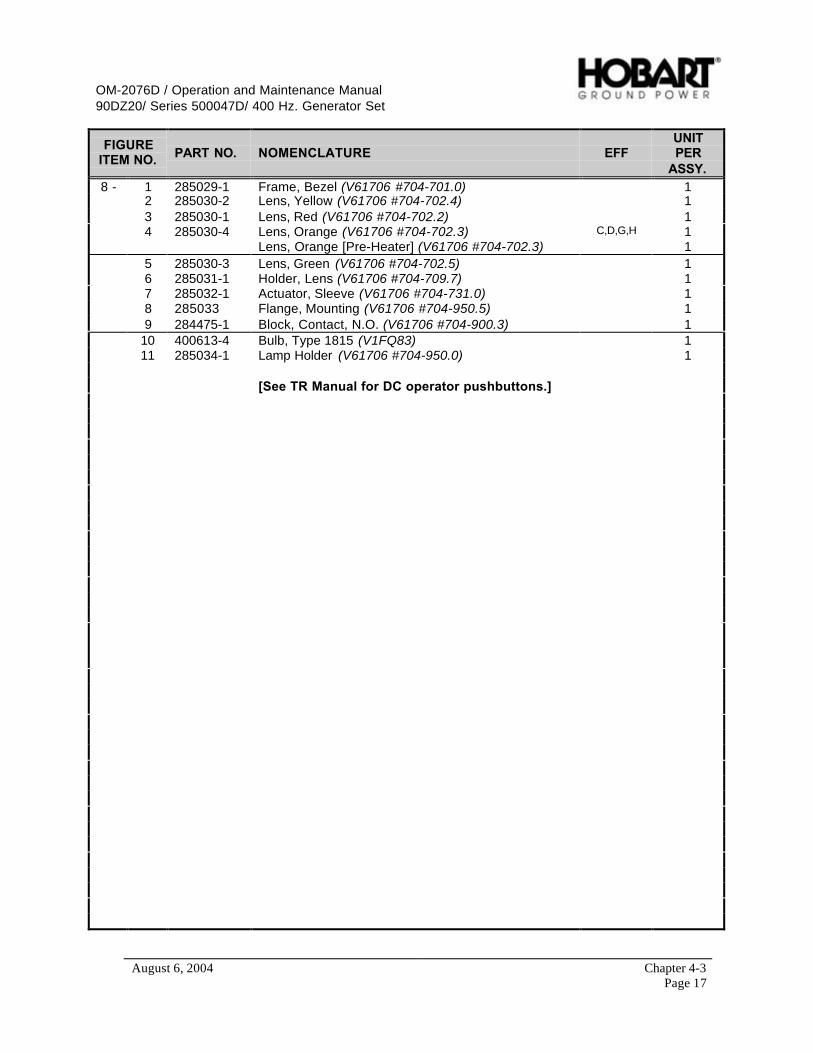
OM-2076D / Operation and Maintenance Manual90DZ20/ Series 500047D/ 400 Hz. Generator Set
August 6, 2004 Chapter 4-3Page 17
FIGUREITEM NO. PART NO. NOMENCLATURE EFF
UNITPER
ASSY.8 - 1 285029-1 Frame, Bezel (V61706 #704-701.0) 1
2 285030-2 Lens, Yellow (V61706 #704-702.4) 13 285030-1 Lens, Red (V61706 #704-702.2) 14 285030-4 Lens, Orange (V61706 #704-702.3) C,D,G,H 1
Lens, Orange [Pre-Heater] (V61706 #704-702.3) 15 285030-3 Lens, Green (V61706 #704-702.5) 16 285031-1 Holder, Lens (V61706 #704-709.7) 17 285032-1 Actuator, Sleeve (V61706 #704-731.0) 18 285033 Flange, Mounting (V61706 #704-950.5) 19 284475-1 Block, Contact, N.O. (V61706 #704-900.3) 1
10 400613-4 Bulb, Type 1815 (V1FQ83) 111 285034-1 Lamp Holder (V61706 #704-950.0) 1
[See TR Manual for DC operator pushbuttons.]
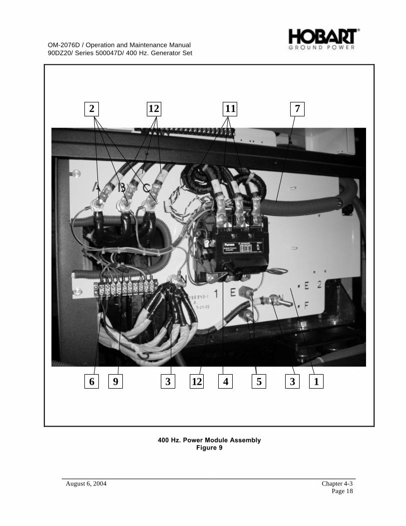
OM-2076D / Operation and Maintenance Manual90DZ20/ Series 500047D/ 400 Hz. Generator Set
August 6, 2004 Chapter 4-3Page 18
1
2
3 4 356
7
9
1112
12
400 Hz. Power Module AssemblyFigure 9

OM-2076D / Operation and Maintenance Manual90DZ20/ Series 500047D/ 400 Hz. Generator Set
August 6, 2004 Chapter 4-3Page 19
FIGUREITEM NO. PART NO. NOMENCLATURE EFF
UNITPER
ASSY.9 - 1 288709 Panel, Power Module 1
2 AW626 Bushing, Insulating [A-B-C] (V1Y498) 3A25 …Washer, Insulating 6
3 AW626 Bushing, Insulating [N] (V1Y498) 2A25 …Washer, Insulating 4
4 282130-1 Contactor, Line, 3-Pole 1* 282130-1 Contactor, Line, 3-Pole C,D,G,H 2
5 286266 Standoff, Short [E-F] 2* 286266 Standoff, Short [E-F] C,D,G,H 4
6 401911-10 Block, Terminal 17 288829 Harness, Wire 1
* 8 288832 Harness, Wire, 2nd Output C,D,G,H 19 282089-10 Diode, Flyback 1
* 10 288892-1 Resistor, GPU ID 111 285102-1 Current, Transformer (V05HB5 # 20130) 3
* 285102-1 Current, Transformer (V05HB5 # 20130) C,D,G,H 612 288829 Cable, Power, Ay. Ref.
…(No. 101) “A” Stator Terminal to “K1”, # 1 Output 1…(No. 102) “B” Stator Terminal to “K1”, # 1 Output 1…(No. 103) “C” Stator Terminal to “K1”, # 1 Output 1…(No. 110) “N” Stator Terminal to “N”, Neutral 1
* 13 288832 Cable, Power, Ay. C,D,G,H
…(No. 104) “A” Stator Terminal to “K201”, # 2 Output 1…(No. 105) “B” Stator Terminal to “K201”, # 2 Output 1…(No. 106) “C” Stator Terminal to “K201”, # 2 Output 1
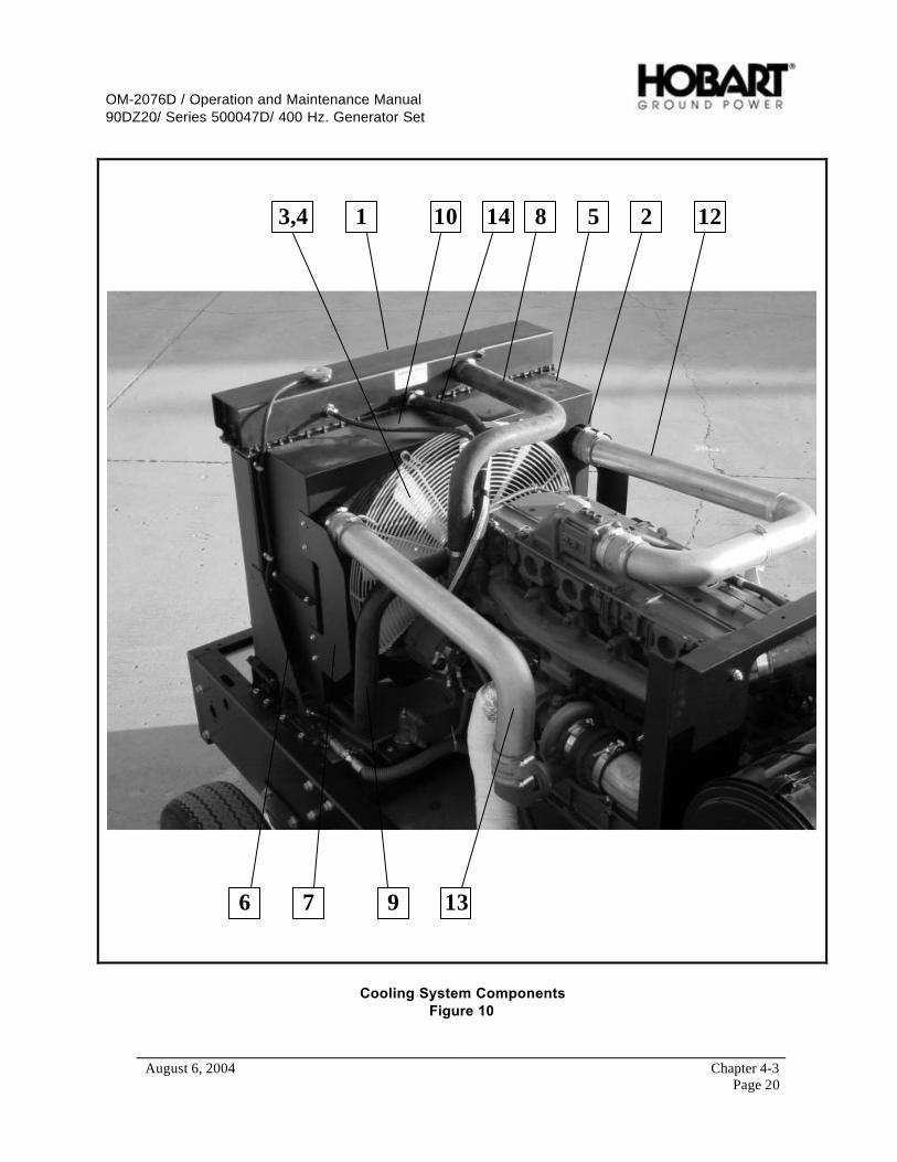
OM-2076D / Operation and Maintenance Manual90DZ20/ Series 500047D/ 400 Hz. Generator Set
August 6, 2004 Chapter 4-3Page 20
1 23,4 5
6 7 9
810 12
13
14
Cooling System ComponentsFigure 10
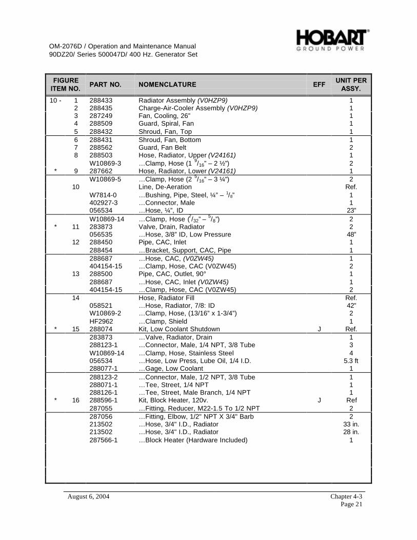
OM-2076D / Operation and Maintenance Manual90DZ20/ Series 500047D/ 400 Hz. Generator Set
August 6, 2004 Chapter 4-3Page 21
FIGUREITEM NO.
PART NO. NOMENCLATURE EFFUNIT PER
ASSY.
10 - 1 288433 Radiator Assembly (V0HZP9) 12 288435 Charge-Air-Cooler Assembly (V0HZP9) 13 287249 Fan, Cooling, 26” 14 288509 Guard, Spiral, Fan 15 288432 Shroud, Fan, Top 16 288431 Shroud, Fan, Bottom 17 288562 Guard, Fan Belt 28 288503 Hose, Radiator, Upper (V24161) 1
W10869-3 …Clamp, Hose (1 9/16” – 2 ½”) 2* 9 287662 Hose, Radiator, Lower (V24161) 1
W10869-5 …Clamp, Hose (2 5/16” – 3 ¼”) 210 Line, De-Aeration Ref.
W7814-0 …Bushing, Pipe, Steel, ¼” – 1/8” 1402927-3 …Connector, Male 1056534 …Hose, ¼”, ID 23”W10869-14 …Clamp, Hose (7/32” – 5/8”) 2
* 11 283873 Valve, Drain, Radiator 2056535 …Hose, 3/8” ID, Low Pressure 48”
12 288450 Pipe, CAC, Inlet 1288454 …Bracket, Support, CAC, Pipe 1288687 …Hose, CAC, (V0ZW45) 1404154-15 …Clamp, Hose, CAC (V0ZW45) 2
13 288500 Pipe, CAC, Outlet, 90° 1288687 …Hose, CAC, Inlet (V0ZW45) 1404154-15 …Clamp, Hose, CAC (V0ZW45) 2
14 Hose, Radiator Fill Ref.058521 …Hose, Radiator, 7/8: ID 42”W10869-2 …Clamp, Hose, (13/16” x 1-3/4”) 2HF2962 …Clamp, Shield 1
* 15 288074 Kit, Low Coolant Shutdown J Ref.283873 …Valve, Radiator, Drain 1288123-1 …Connector, Male, 1/4 NPT, 3/8 Tube 3W10869-14 …Clamp, Hose, Stainless Steel 4056534 …Hose, Low Press, Lube Oil, 1/4 I.D. 5.3 ft288077-1 …Gage, Low Coolant 1288123-2 …Connector, Male, 1/2 NPT, 3/8 Tube 1288071-1 …Tee, Street, 1/4 NPT 1288126-1 …Tee, Street, Male Branch, 1/4 NPT 1
* 16 288596-1 Kit, Block Heater, 120v. J Ref287055 …Fitting, Reducer, M22-1.5 To 1/2 NPT 2287056 …Fitting, Elbow, 1/2" NPT X 3/4" Barb 2213502 …Hose, 3/4" I.D., Radiator 33 in.213502 …Hose, 3/4" I.D., Radiator 28 in.287566-1 …Block Heater (Hardware Included) 1

OM-2076D / Operation and Maintenance Manual90DZ20/ Series 500047D/ 400 Hz. Generator Set
August 6, 2004 Chapter 4-3Page 22
1
3 2
4
Engine Ground Plate and CablesFigure 11
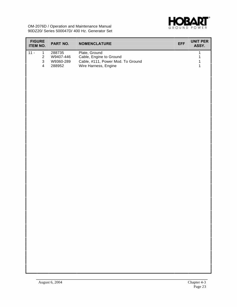
OM-2076D / Operation and Maintenance Manual90DZ20/ Series 500047D/ 400 Hz. Generator Set
August 6, 2004 Chapter 4-3Page 23
FIGUREITEM NO. PART NO. NOMENCLATURE EFF
UNIT PERASSY.
11 - 1 288735 Plate, Ground 12 W9407-446 Cable, Engine to Ground 13 W9360-289 Cable, #111, Power Mod. To Ground 14 288952 Wire Harness, Engine 1
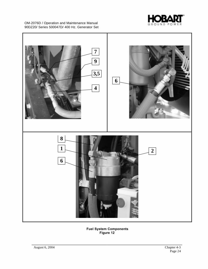
OM-2076D / Operation and Maintenance Manual90DZ20/ Series 500047D/ 400 Hz. Generator Set
August 6, 2004 Chapter 4-3Page 24
3,5
4
9
7
6
1 2
6
8
Fuel System ComponentsFigure 12

OM-2076D / Operation and Maintenance Manual90DZ20/ Series 500047D/ 400 Hz. Generator Set
August 6, 2004 Chapter 4-3Page 25
FIGUREITEM NO. PART NO. NOMENCLATURE EFF
UNIT PERASSY.
12 - 1 No Number Filter, Fuel/Water, Separator (V0ZW45 # 1340130) Ref.286897-13 ….Filter, Fuel, Replacement (V0ZW45 # 117-4421) 1
2 288585 Line, Fuel, Tank to Filter 13 12CW2077-3 Elbow, ½” NPT, ST., 90° 14 400819-3 Valve, Ball, ½” NPT 15 W10760-3 Nipple, Pipe, ½” 16 288586 Line, Fuel, Filter to Pump 17 Line, Fuel, Return Ref.
056535 …Hose, 3/8” ID 72”W10869-14 …Clamp, Hose ( 7/32 – 5/8) 2286851 …Fitting, Hose, Barbed, Brass 1288248 …Fitting, Fuel Return Straight 176A1132 …Tubing, Z-Flex, ¾” ID 66”
8 288587 Bracket, Engine Fuel Filter 19 287781 Tank, Fuel, 65 Gallon 1
* 10 282562 Cap, Fuel Neck (V49234 #1275G/12T) 1* 11 288188 Filter, Fuel/Water, Separator J 1
(V1PAM0 # 382050CMDV)* 12 289166 Line, Fuel, Tank to Filter J 1* 13 289165 Line, Fuel, Filter to Pump J 1* 14 289188 Bracket, Engine Fuel Filter J 1

OM-2076D / Operation and Maintenance Manual90DZ20/ Series 500047D/ 400 Hz. Generator Set
August 6, 2004 Chapter 4-3Page 26
12,3
5,6
79
Engine Exhaust ComponentsFigure 13

OM-2076D / Operation and Maintenance Manual90DZ20/ Series 500047D/ 400 Hz. Generator Set
August 6, 2004 Chapter 4-3Page 27
FIGUREITEM NO. PART NO. NOMENCLATURE EFF
UNIT PERASSY.
13 - 1 288968 Muffler and Exhaust Ay. 12 287431 Bracket, Muffler Mounting, Front A,C,E,G,J 1
287431 Bracket, Muffler Mounting, Front B,D,F,H 23 287432 Bracket, Muffler Mounting, Rear 1
* 4 287691 Spring, Muffler, Mounting 45 288969 Pipe, Turbo, Ay. 16 404154-16 Clamp, Pipe, 4” 37 287406 Shield, Heat, Muffler A,C,E,G,J 1
* 287644 Shield, Heat, Muffler B,D,F,H 1* 287647 Shield, Heat, Muffler [End] B,D,F,H 1* 8 287645 Support, Exhaust Pipe B,D,F,H 1
9 287370 Pipe, Exhaust Ay. A,C,E,G,J 1* 287643 Pipe, Exhaust Ay. B,D,F,H 1
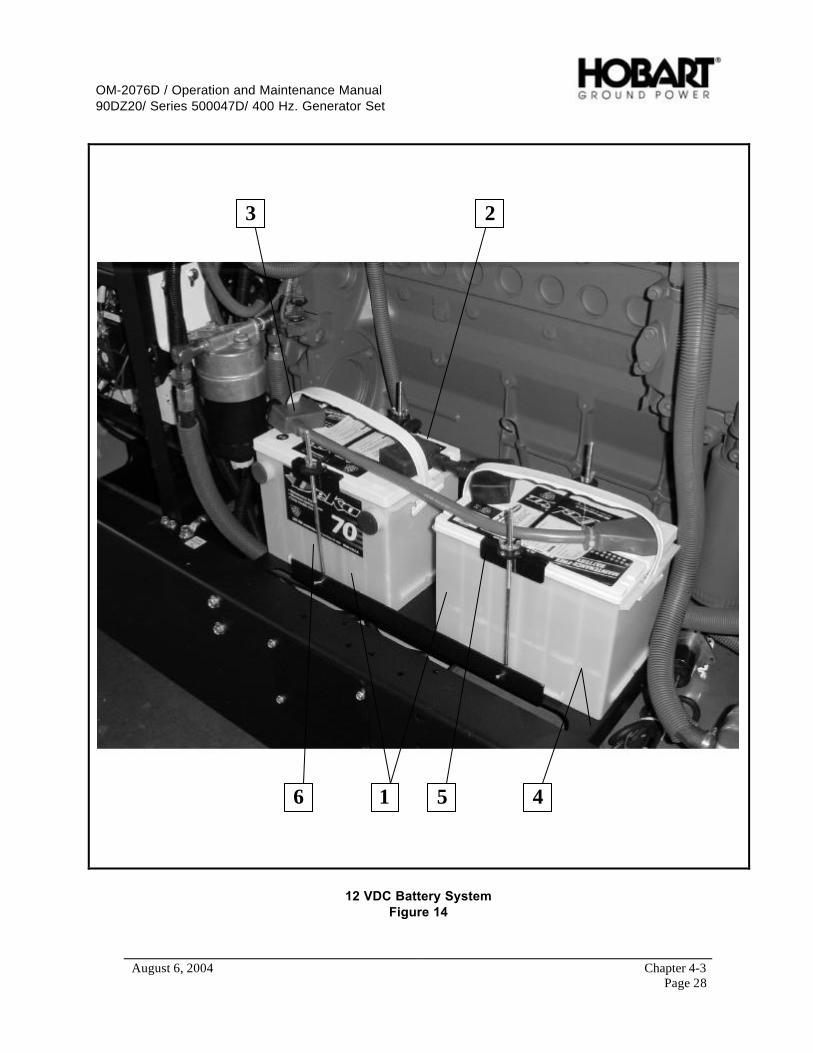
OM-2076D / Operation and Maintenance Manual90DZ20/ Series 500047D/ 400 Hz. Generator Set
August 6, 2004 Chapter 4-3Page 28
1
3 2
456
12 VDC Battery SystemFigure 14
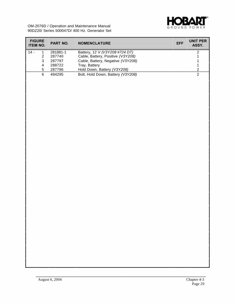
OM-2076D / Operation and Maintenance Manual90DZ20/ Series 500047D/ 400 Hz. Generator Set
August 6, 2004 Chapter 4-3Page 29
FIGUREITEM NO. PART NO. NOMENCLATURE EFF
UNIT PERASSY.
14 - 1 281881-1 Battery, 12 V (V3Y208 #724 DT) 22 287740 Cable, Battery, Positive (V3Y208) 13 287797 Cable, Battery, Negative (V3Y208) 14 288722 Tray, Battery 15 287796 Hold Down, Battery (V3Y208) 26 494295 Bolt, Hold Down, Battery (V3Y208) 2

OM-2076D / Operation and Maintenance Manual90DZ20/ Series 500047D/ 400 Hz. Generator Set
August 6, 2004 Chapter 4-3Page 30
1
2
74 675 3
8
9
10
Air Cleaner ComponentsFigure 15

OM-2076D / Operation and Maintenance Manual90DZ20/ Series 500047D/ 400 Hz. Generator Set
August 6, 2004 Chapter 4-3Page 31
FIGUREITEM NO. PART NO. NOMENCLATURE EFF
UNIT PERASSY.
15 - 1 286061 Air Cleaner (V18265 #EBB12-0271) 12 284923 Mount, Band, Air Cleaner (V18265 #AAH00-0349) 23 282918 Indicator, Restriction, Electric (V18265 #REX77-0062) 14 288588 Pipe, Air Inlet, Ay. 15 287371 Elbow, Rubber, 90° (V55752 # 4014-03002) 16 284925 Reducer, Rubber, 90° Elbow (V18265 # P12-1482) 17 280732-6 Clamp, T-Bolt (V18265 # P148343) 48 280732-7 Clamp, T-Bolt (V18265 # P148345) 19 403484 Reducer, Hump, Rubber 1
10 288054-3 Elbow, Steel, 90° 1

OM-2076D / Operation and Maintenance Manual90DZ20/ Series 500047D/ 400 Hz. Generator Set
August 6, 2004 Chapter 4-3Page 32
1
23 4 5 6 7
8
Engine Electronic Panel ComponentsFigure 16
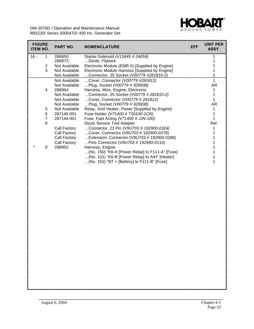
OM-2076D / Operation and Maintenance Manual90DZ20/ Series 500047D/ 400 Hz. Generator Set
August 6, 2004 Chapter 4-3Page 33
FIGUREITEM NO. PART NO. NOMENCLATURE EFF
UNIT PERASSY.
16 - 1 286850 Starter Solenoid (V13445 # 24059) 1288973 …Diode, Flyback 1
2 Not Available Electronic Module (EMR II) [Supplied by Engine] 13 Not Available Electronic Module Harness [Supplied by Engine] 1
Not Available …Connector, 25 Socket (V00779 #281810-2) 1Not Available …Cover, Connector (V00779 #281812) 1Not Available …Plug, Socket (V00779 # 929938) AR
4 288964 Harness, Wire, Engine, Electronic 1Not Available …Connector, 25 Socket (V00779 # 281810-2) 1Not Available …Cover, Connector (V00779 # 281812) 1Not Available …Plug, Socket (V00779 # 929938) AR
5 Not Available Relay, Grid Heater, Power [Supplied by Engine] 16 287145-001 Fuse Holder (V71400 # T30100-1CR) 17 287144-001 Fuse, Fast Acting (V71400 # JJN-100) 18 Deutz Service Tool Adapter Ref.
Call Factory …Connector, 23 Pin (V9U703 # 192900-0324) 1Call Factory …Cover, Connector (V9U703 # 192900-0378) 1Call Factory …Extension, Connector (V9U703 # 192900-0286) 1Call Factory …Pins Connector (V9U703 # 192990-0110) 1
* 9 288952 Harness, Engine 1…(No. 150) “K6-A [Power Relay] to F111-A” [Fuse] 1…(No. 151) “K6-B [Power Relay] to AIH” [Heater] 1…(No. 152) “BT + [Battery] to F111-B” [Fuse] 1
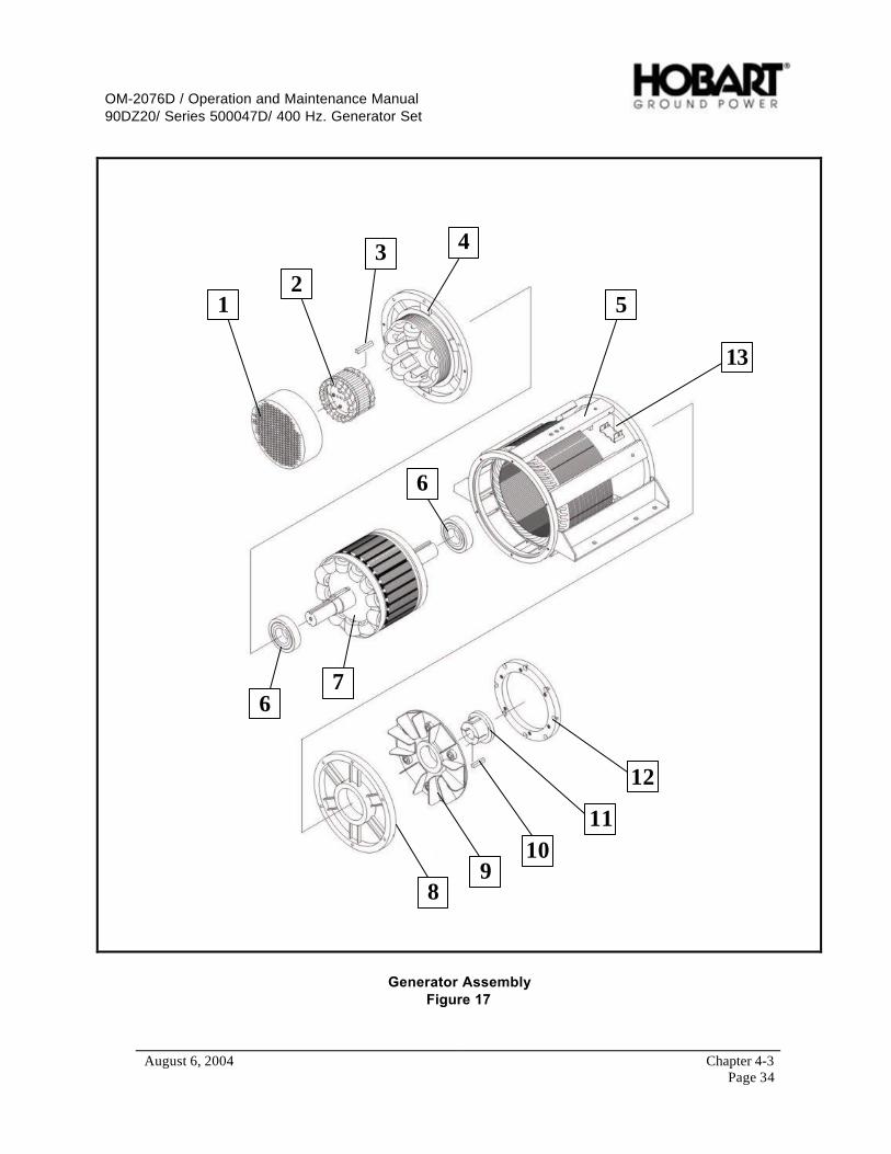
OM-2076D / Operation and Maintenance Manual90DZ20/ Series 500047D/ 400 Hz. Generator Set
August 6, 2004 Chapter 4-3Page 34
12
3 4
5
6
67
89
1011
12
13
Generator AssemblyFigure 17
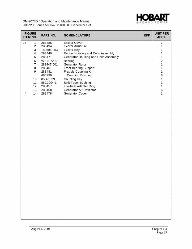
OM-2076D / Operation and Maintenance Manual90DZ20/ Series 500047D/ 400 Hz. Generator Set
August 6, 2004 Chapter 4-3Page 35
FIGUREITEM NO. PART NO. NOMENCLATURE EFF
UNIT PERASSY.
17 - 1 288486 Exciter Cover 12 288494 Exciter Armature 13 180696-003 Exciter Key 14 288440 Exciter Housing and Coils Assembly 15 288471 Generator Housing and Coils Assembly 16 W-10072-68 Bearing 27 288447-001 Generator Rotor 18 288461 Front Bearing Support 19 288481 Flexible Coupling Kit 1
480290 …Coupling Bushing 810 85B-1039 Coupling Key 111 85C1004-1 Split Taper Bushing 112 288457 Flywheel Adapter Ring 113 288458 Generator Air Deflector 6
* 14 288478 Generator Cover 1

OM-2076D / Operation and Maintenance Manual90DZ20/ Series 500047D/ 400 Hz. Generator Set
August 6, 2004 Chapter 4-3Page 36
This page intentionally left blank.
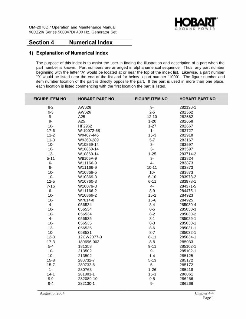
OM-2076D / Operation and Maintenance Manual90DZ20/ Series 500047D/ 400 Hz. Generator Set
August 6, 2004 Chapter 4-4Page 1
Section 4 Numerical Index
1) Explanation of Numerical Index
The purpose of this index is to assist the user in finding the illustration and description of a part when thepart number is known. Part numbers are arranged in alphanumerical sequence. Thus, any part numberbeginning with the letter “A” would be located at or near the top of the index list. Likewise, a part number“9” would be listed near the end of the list and far below a part number “1000”. The figure number anditem number location of the part is directly opposite the part. If the part is used in more than one place,each location is listed commencing with the first location the part is listed.
FIGURE ITEM NO. HOBART PART NO. FIGURE ITEM NO. HOBART PART NO.
9-2 AW626 9- 282130-19-3 AW626 2-5 2825629- A25 12-10 2825629- A25 1-20 28265810- HF2962 1-27 282667
17-6 W-10072-68 1- 28272711-2 W9407-446 15-3 28291811-3 W9360-289 5-7 28316710- W10869-14 3- 28359710- W10869-14 3- 28359712- W10869-14 1-25 283714-2
5-11 W8105A-9 3- 2838246- W11166-9 4- 2838736- W11166-9 10-11 28387310- W10869-5 10- 28387310- W10869-3 6-10 283978-2
12-5 W10760-3 6-11 283978-17-16 W10079-3 4- 284371-56- W11166-2 8-9 284475-110- W10869-2 15-2 28492310- W7814-0 15-6 2849254- 056534 8-4 285030-410- 056534 8-5 285030-310- 056534 8-2 285030-24- 056535 8-1 285029-110- 056535 8-3 285030-112- 056535 8-6 285031-110- 058521 8-7 285032-1
12-3 12CW2077-3 8-11 285034-117-3 180696-003 8-8 2850335-4 181358 9-11 285102-110- 213502 9- 285102-110- 213502 1-4 285125
15-8 280732-7 5-13 28517215-7 280732-6 5- 2851721- 280763 1-26 285418
14-1 281881-1 15-1 2860619-9 282089-10 9-5 2862669-4 282130-1 9- 286266
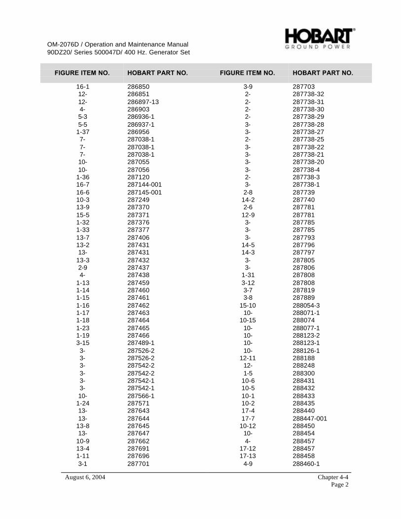
OM-2076D / Operation and Maintenance Manual90DZ20/ Series 500047D/ 400 Hz. Generator Set
August 6, 2004 Chapter 4-4Page 2
FIGURE ITEM NO. HOBART PART NO. FIGURE ITEM NO. HOBART PART NO.
16-1 286850 3-9 28770312- 286851 2- 287738-3212- 286897-13 2- 287738-314- 286903 2- 287738-305-3 286936-1 2- 287738-295-5 286937-1 3- 287738-28
1-37 286956 3- 287738-277- 287038-1 2- 287738-257- 287038-1 3- 287738-227- 287038-1 3- 287738-2110- 287055 3- 287738-2010- 287056 3- 287738-4
1-36 287120 2- 287738-316-7 287144-001 3- 287738-116-6 287145-001 2-8 28773910-3 287249 14-2 28774013-9 287370 2-6 28778115-5 287371 12-9 2877811-32 287376 3- 2877851-33 287377 3- 28778513-7 287406 3- 28779313-2 287431 14-5 28779613- 287431 14-3 287797
13-3 287432 3- 2878052-9 287437 3- 2878064- 287438 1-31 287808
1-13 287459 3-12 2878081-14 287460 3-7 2878191-15 287461 3-8 2878891-16 287462 15-10 288054-31-17 287463 10- 288071-11-18 287464 10-15 2880741-23 287465 10- 288077-11-19 287466 10- 288123-23-15 287489-1 10- 288123-13- 287526-2 10- 288126-13- 287526-2 12-11 2881883- 287542-2 12- 2882483- 287542-2 1-5 2883003- 287542-1 10-6 2884313- 287542-1 10-5 28843210- 287566-1 10-1 288433
1-24 287571 10-2 28843513- 287643 17-4 28844013- 287644 17-7 288447-001
13-8 287645 10-12 28845013- 287647 10- 288454
10-9 287662 4- 28845713-4 287691 17-12 2884571-11 287696 17-13 2884583-1 287701 4-9 288460-1

OM-2076D / Operation and Maintenance Manual90DZ20/ Series 500047D/ 400 Hz. Generator Set
August 6, 2004 Chapter 4-4Page 3
FIGURE ITEM NO. HOBART PART NO. FIGURE ITEM NO. HOBART PART NO.
17-8 288461 5-17 28880617-5 288471 5-10 288814-2
17-14 288478 6- 28881317-9 288481 6-8 288818-117-1 288486 5-6 288819-117-2 288494 5- 288820
10-13 288500 9-7 28882910-8 288503 9-12 2888292-7 288507 9-8 288832
10-4 288509 9-13 2888323-3 288544 5-14 288836-23-4 288547 5- 288836-1
4-14 288555 2-3 288835A10-7 288562 4-18 288835A12-2 288585 4- 288840-212-6 288586 4-3 288840-112-8 288587 4- 288847-115-4 288588 5-9 288858-4
10-16 288596-1 1-22 2888626- 288605 1-21 28886610- 288687 7-18 28887210- 288687 6- 2888752-2 288691A 6- 288876
4-17 288691A 3-10 2888782-14 288692 2-1 2888794-15 288692 3-2 2888802-15 288693 3- 2888814-16 288693 2-12 2888821- 288694 9-10 288892-11- 288694 4-19 288895
3-14 288694 6- 2888962- 288702-7 6-14 2889141- 288695 6-15 288917-21- 288695 6-16 288918-2
1-29 288696 3-6 2889191-28 288697 6-5 2889371- 288698 6-6 288940
2-13 288699 4-12 2889523-13 288700 11-4 2889522-10 288701 16-9 2889521-35 288703 4-13 2889642-11 288704 16-4 2889649-1 288709 1-34 2889672-4 288722 13-1 288968
14-4 288722 13-5 28896911-1 288735 16- 2889736-4 288742 6-3 288992
7-13 288771 6-2 2889937-12 288772 6-1 2889947-11 288773 5-2 2889956- 288791 5-12 288999-1

OM-2076D / Operation and Maintenance Manual90DZ20/ Series 500047D/ 400 Hz. Generator Set
August 6, 2004 Chapter 4-4Page 4
FIGURE ITEM NO. HOBART PART NO. FIGURE ITEM NO. HOBART PART NO.
7-14 2890044- 289012-44- 289012-34- 289012-24-2 289012-1
7-15 2890144- 289019-45- 289018-3
7-17 2890154-1 289019-35- 289018-15-8 2890176-7 2890266-9 2890596- 289060
6-13 2890726-12 2890734- 289127
12-13 28916512-12 2891661-10 289177-2
12-14 2891888-10 400613-45-15 400641-155-16 400642-812-4 400819-39-6 401911-1010- 402927-3
3-11 403091-83-5 403091-23- 403127
15-9 40348413-6 404154-1610- 404154-1510- 404154-151-8 408665-21-7 408665-11- 408781-117- 4802904- 480603-15-1 494134-1
14-6 4942951-9 4025987
1-30 7J422-01-12 76B114812- 76A11321-6 77A1157
17-10 85B-103917-11 85C1004-1
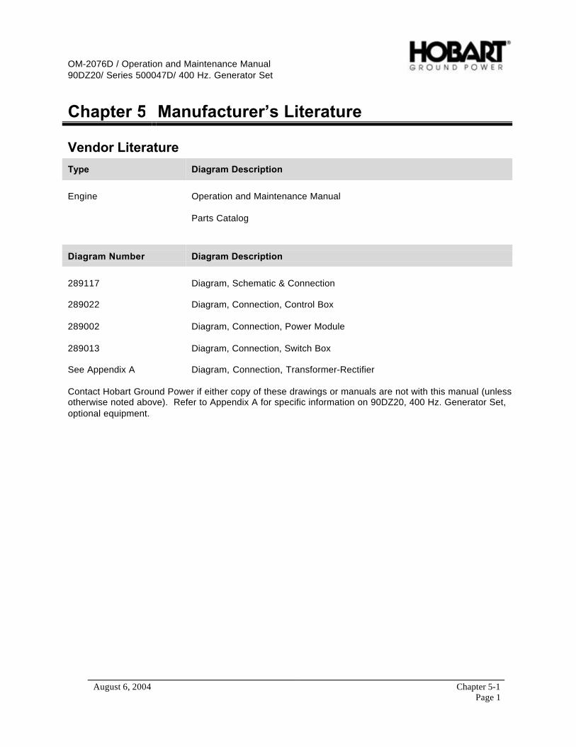
OM-2076D / Operation and Maintenance Manual90DZ20/ Series 500047D/ 400 Hz. Generator Set
August 6, 2004 Chapter 5-1Page 1
Chapter 5 Manufacturer’s Literature
Vendor Literature
Type Diagram Description
Engine Operation and Maintenance Manual
Parts Catalog
Diagram Number Diagram Description
289117 Diagram, Schematic & Connection
289022 Diagram, Connection, Control Box
289002 Diagram, Connection, Power Module
289013 Diagram, Connection, Switch Box
See Appendix A Diagram, Connection, Transformer-Rectifier
Contact Hobart Ground Power if either copy of these drawings or manuals are not with this manual (unlessotherwise noted above). Refer to Appendix A for specific information on 90DZ20, 400 Hz. Generator Set,optional equipment.

OM-2076D / Operation and Maintenance Manual90DZ20/ Series 500047D/ 400 Hz. Generator Set
August 6, 2004 Chapter 5-1Page 2
This page intentionally left blank.
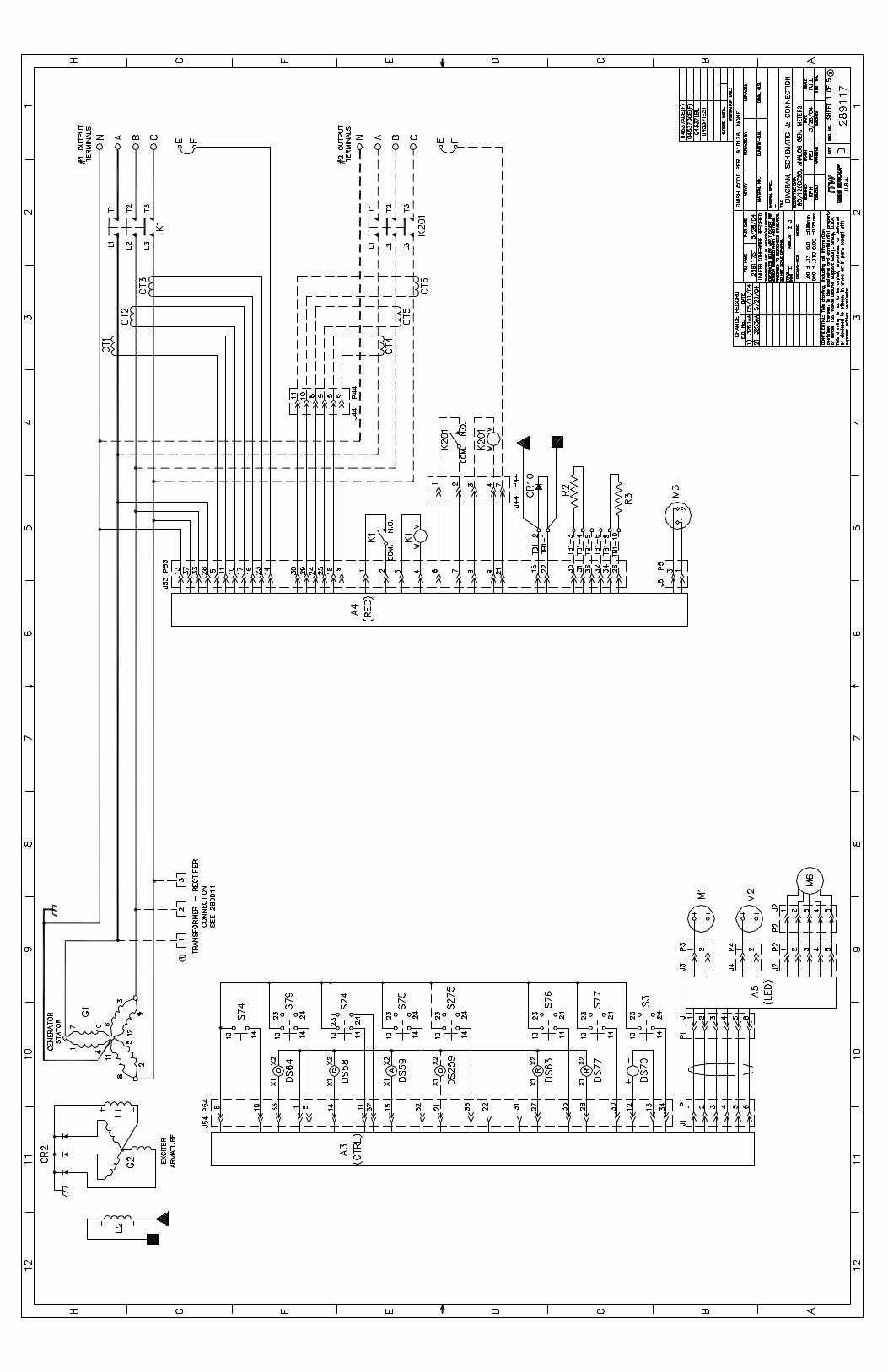


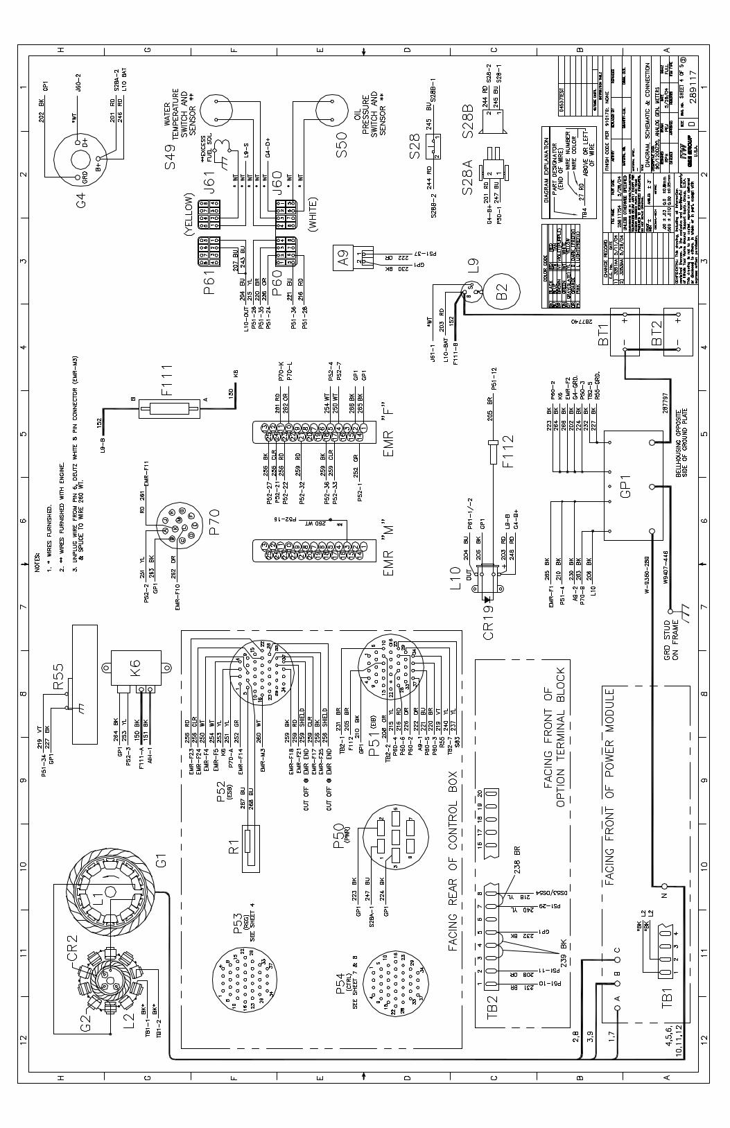


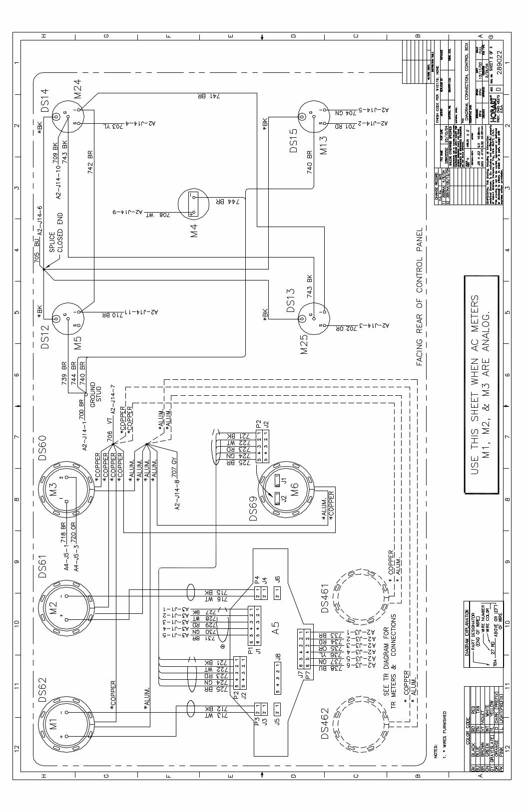

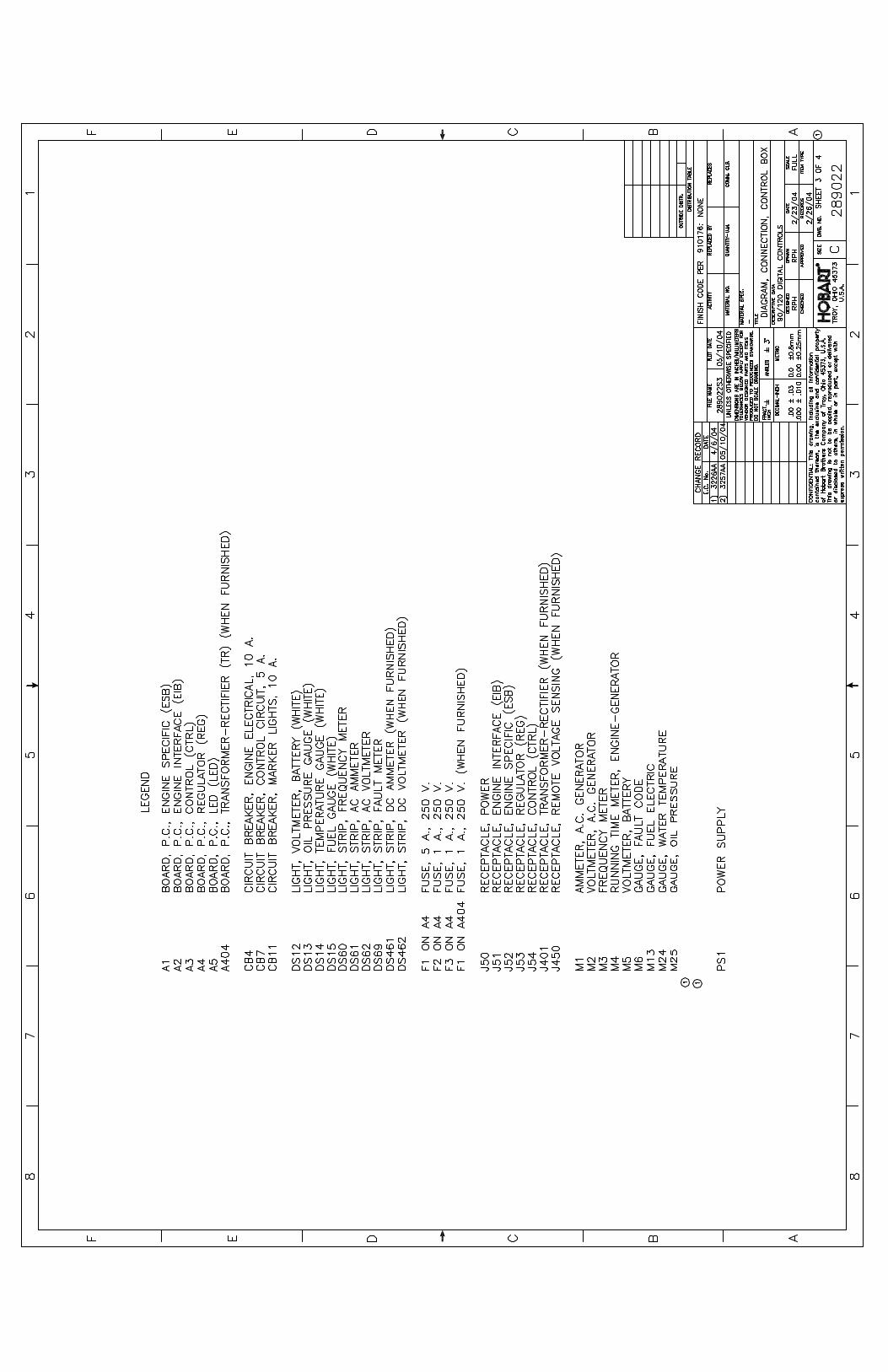

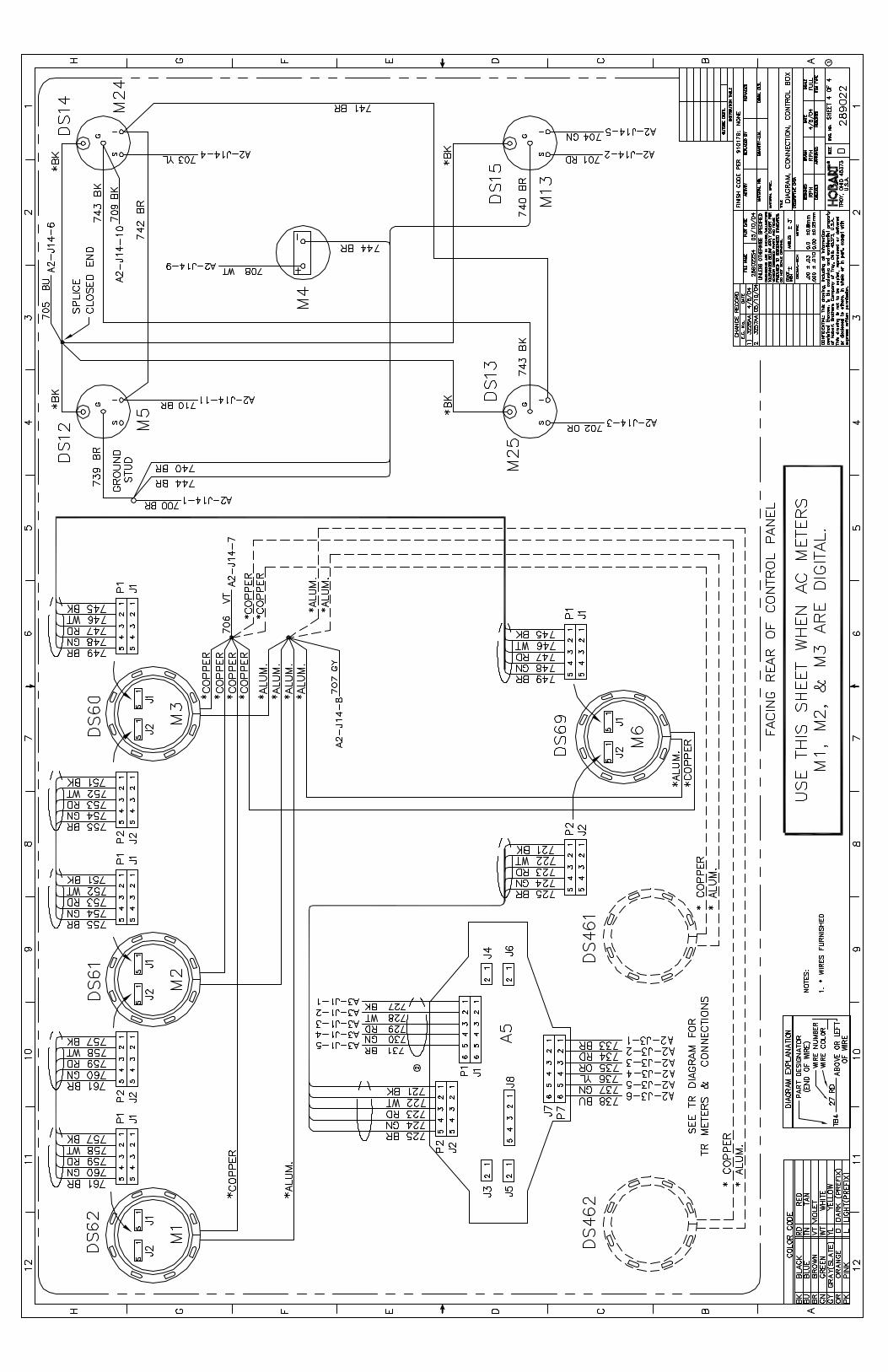

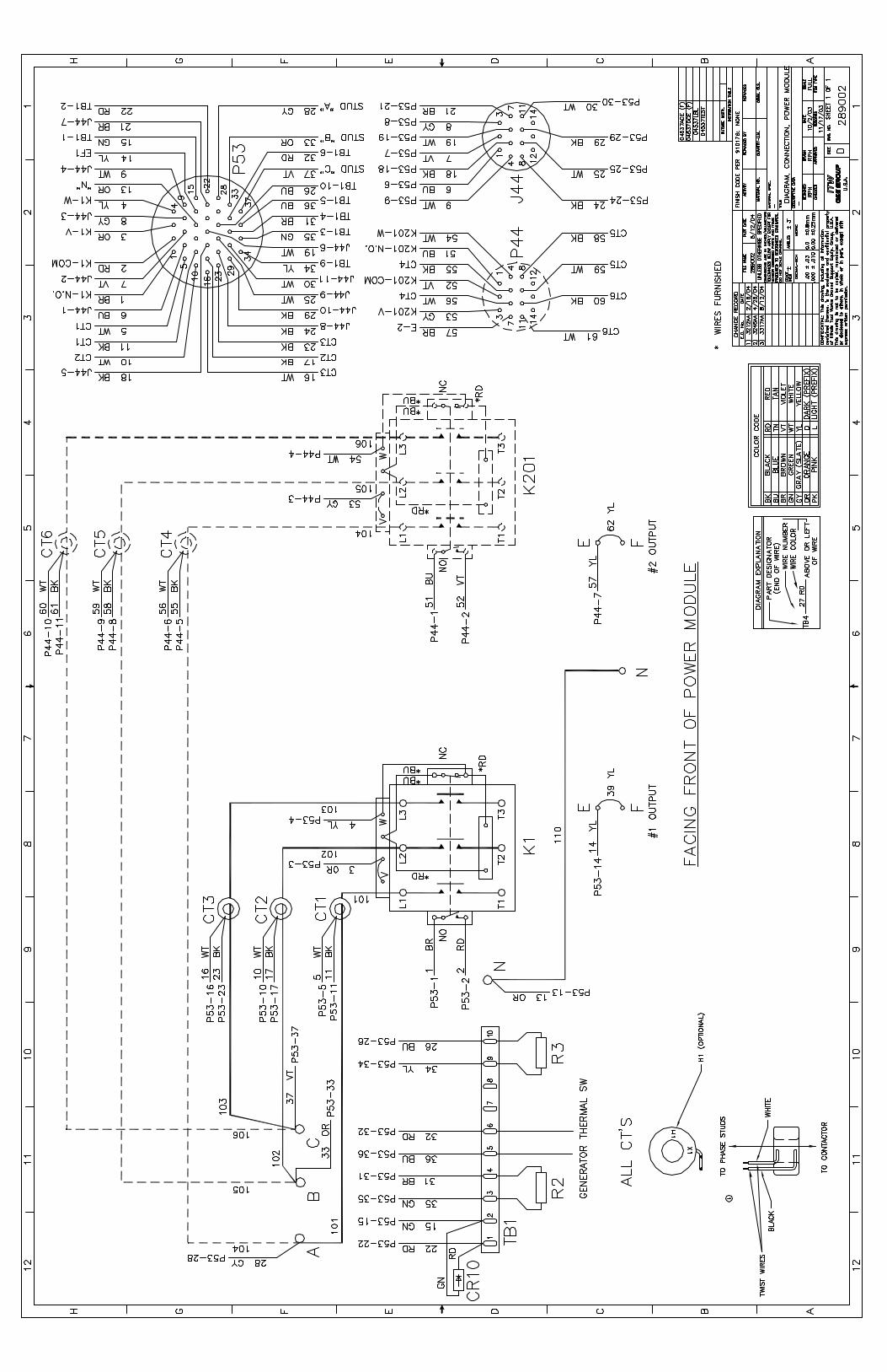


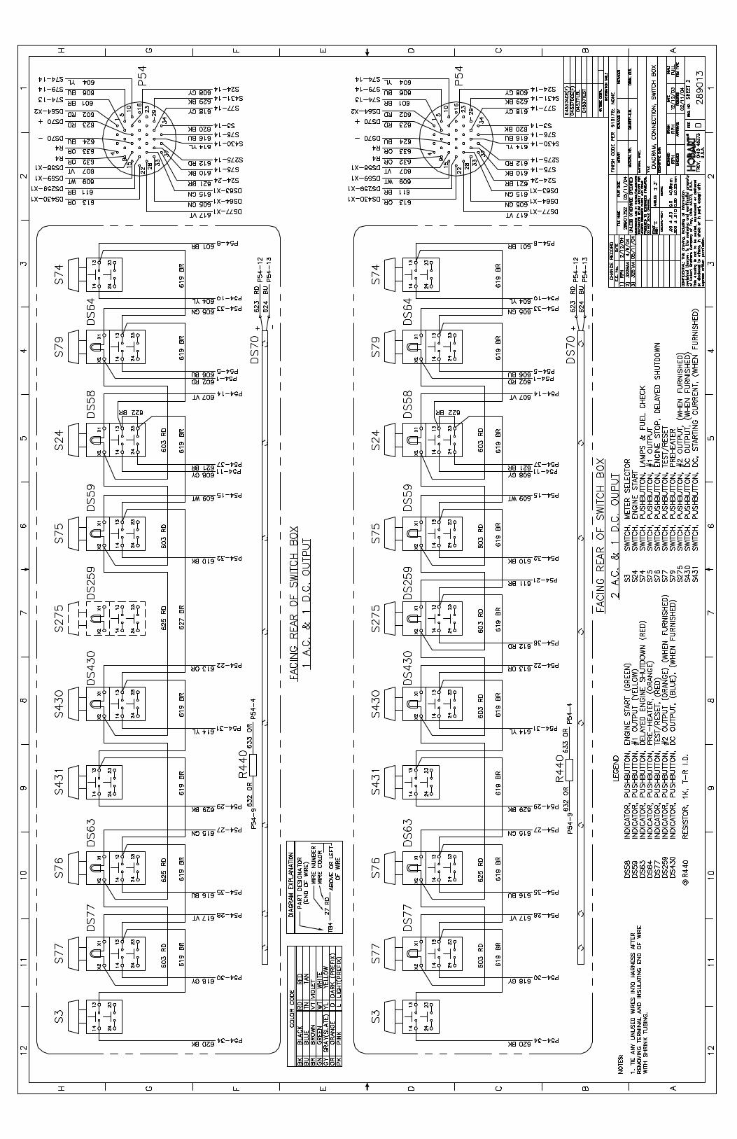


OM-2076D / Operation and Maintenance Manual90DZ20/ Series 500047D/ 400 Hz. Generator Set
August 6, 2004 Appendix APage 1
Appendix A Options / Features
Option/Features Available
Description Part NumberDocumentNumber
In ThisSection
Trailer, with Tongue Actuated Brakes/Cable Trays Standard TO-257Trailer, with Lever Actuated Brakes/Cable Trays Call Factory TO-241Kit, Noise Reduction 288865 n/aKit, Spotlight 287122 n/aKit, Block Heater, 120V 288596-1 288596Kit, Block Heater, 240V 288596-2 288596Kit, Fire Extinguisher 283012 TO-252Kit, Pin Hitch 381441 381441Kit, Pintle Hitch 76A1361 76A1361Kit, Fixed Mounting 287892 n/aSupport, Fork Lift Assembly 287694 TO-281Kit, Tie-Down 284706 n/a*Kit, Unit Operating, Non-Flashing Beacon 288909-XXX n/a*Kit, Low Fuel, Flashing/Non-Flashing Beacon Call Factory n/a*Kit, Low Fuel Strobe Beacon Call Factory n/aKit, Battery Blanket, 120V 287917 n/aDrawbar, 1-1/2” Eye 286944 n/aKit, T-Handle Latch 287546-2 n/aWheel Chocks 287609 n/aKit, Clearance Lights 288912 TO-297Kit, Transformer-Rectifier, 28 VDC Call Factory OM-2136
* – A large number of variations exist under this part number. Call the factory for details.n/a – Not Available, call the factory for details.
The following is a list of options/features available for the 90DZ20, 400 Hz. Generator Set. This chartcontains the description, part number, and document number (if applicable) of the option/feature. There isalso a column to identify which option/feature document is contained in this Appendix.

OM-2076D / Operation and Maintenance Manual90DZ20/ Series 500047D/ 400 Hz. Generator Set
August 6, 2004 Appendix APage 2
This page intentionally left blank.
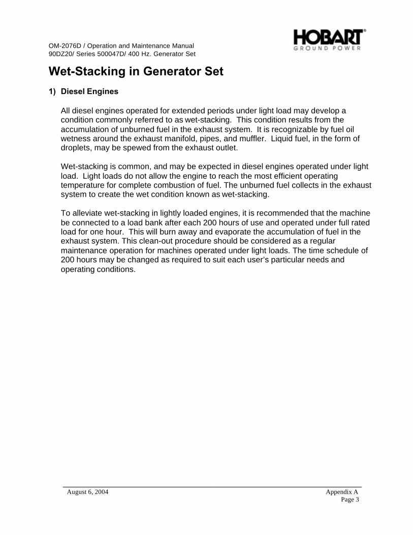
OM-2076D / Operation and Maintenance Manual90DZ20/ Series 500047D/ 400 Hz. Generator Set
August 6, 2004 Appendix APage 3
Wet-Stacking in Generator Set
1) Diesel Engines
All diesel engines operated for extended periods under light load may develop acondition commonly referred to as wet-stacking. This condition results from theaccumulation of unburned fuel in the exhaust system. It is recognizable by fuel oilwetness around the exhaust manifold, pipes, and muffler. Liquid fuel, in the form ofdroplets, may be spewed from the exhaust outlet.
Wet-stacking is common, and may be expected in diesel engines operated under lightload. Light loads do not allow the engine to reach the most efficient operatingtemperature for complete combustion of fuel. The unburned fuel collects in the exhaustsystem to create the wet condition known as wet-stacking.
To alleviate wet-stacking in lightly loaded engines, it is recommended that the machinebe connected to a load bank after each 200 hours of use and operated under full ratedload for one hour. This will burn away and evaporate the accumulation of fuel in theexhaust system. This clean-out procedure should be considered as a regularmaintenance operation for machines operated under light loads. The time schedule of200 hours may be changed as required to suit each user’s particular needs andoperating conditions.

OM-2076D / Operation and Maintenance Manual90DZ20/ Series 500047D/ 400 Hz. Generator Set
August 6, 2004 Appendix APage 4
This page intentionally left blank.
OM-2076D / Operation and Maintenance Manual90DZ20/ Series 500047D/ 400 Hz. Generator Set
August 6, 2004 Appendix APage 5
Unusual Service ConditionsThis information is a general guideline and cannot cover all possible conditions of equipment use. Thespecific local environments may be dependent upon conditions beyond the manufacturer’s control. Themanufacturer should be consulted if any unusual conditions of use exist which may affect the physicalcondition or operation of the equipment.
Among such conditions are:
1) Exposure to:
a) Combustible, explosive, abrasive or conducting dusts.
b) Environments where the accumulation of lint or excessive dirt will interfere with normal ventilation.
c) Chemical fumes, flammable, or explosive gases.
d) Nuclear radiation.
e) Steam, salt-laden air, or oil vapor.
f) Damp or very dry locations, radiant heat, vermin infestation, or atmospheres conducive to fungusgrowth.
g) Abnormal shock, vibration or mechanical loading from external sources during equipment operation.
h) Abnormal axial or side thrust imposed on rotating equipment shafts.
i) Low and/or high ambient temperatures.
j) High electromagnetic fields
2) Operation at:
a) Voltages above or below rated voltage.
b) Speeds other than rated speed.
c) Frequency other than rated frequency.
d) Standstill with rotating equipment windings energized.
e) Unbalanced voltages.
f) Operation at loads greater than rated.
3) Operation where low acoustical noise levels are required.

OM-2076D / Operation and Maintenance Manual90DZ20/ Series 500047D/ 400 Hz. Generator Set
August 6, 2004 Appendix APage 6
4) Operation with:
a) Improper fuel, lubricants or coolant.
b) Parts or elements unauthorized by the manufacturer.
c) Unauthorized modifications.
5) Operation in poorly ventilated areas.