Embed Size (px)
Citation preview
OM-2010121585
Revised 121691031893
OPERATION AND MAINTENANCE
MANUAL
with
ILLUSTRATED PARTS LIST
for
GPU-600
SOLID STATE TRANSFORMER-RECTIFIER
RATED OUTPUT: 28 V-DC, 600 A
SPECIFICATION INPUT VOLTAGE FREQUENCY MODEL NUMBER
S6883-1 208/230/460 V, 3-PHASE 60-Hz 6T28-600CLS6883-2 220/380 V, 3-PHASE 50-Hz 5T28-600CLS6883A-1 208/230/460 V, 3-PHASE 60-Hz 6T28-600CLS6883A-2 220/380 V, 3-PHASE 50-Hz 5T28-600CLS6883A-3 230/460/575 V, 3-PHASE 60-Hz 6T28-600CL
Manufactured byHOBART BROTHERS COMPANY
POWER SYSTEMS GROUPGROUND POWER EQUIPMENT
TROY, OHIO 45373U.S.A.

This page intentionally left blank
SAFETY INSTRUCTIONS AND WARNINGS FOR ELECTRICAL POWER EQUIPMENTWARNINGELECTRIC SHOCK can KILL . Do not touch live electrical parts.
ELECTRIC ARC FLASH can injure eyes, burn skin, cause equipment damage, and ignite combustiblematerial. DO NOT use power cables to break load and prevent tools from causing short circuits.
IMPROPER PHASE CONNECTION, PARALLELING, OR USE can damage this and attachedequipment.
Important: - Protect all operating personnel. Read, understand, and follow all instructions inthe Operating/Instruction Manual before installing, operating, or servicing the equipment. Keep themanual available for future use by all operators.
A. GENERALEquipment that supplies electrical power can cause serious injury or death, or damage to other equipment
or property. The operator must strictly observe all safety rules and take precautionary actions. Safe practiceshave been developed from past experience in the use of power source equipment. While certain practices be-low apply only to electrically-powered equipment, other practices apply to engine-driven equipment, andsome practices to both.
B. SHOCK PREVENTIONBare conductors, or terminals in the output circuit, or ungrounded, electrically-live equipment can fatally
shock a person. Have a certified electrician verify that the equipment is adequately grounded and learn whatterminals and parts are electrically HOT. Avoid hot spots on machine. Use proper safety clothing, proce-dures, and test equipment.
The electrical resistance of the body is decreased when wet, permitting dangerous currents to flowthrough it. When inspecting or servicing equipment, do not work in damp areas. Stand on a dry rubber mator dry wood, use insulating gloves when dampness or sweat cannot be avoided. Keep clothing dry, andnever work alone
1. Installation and Grounding of Electrically Powered EquipmentEquipment driven by electric motors (rather than by diesel or gasoline engines) must be installed and
maintained in accordance with the National Electrical Code, ANSI/NFPA 70, or other applicable codes. Apower disconnect switch or circuit breaker must be located at the equipment. Check the nameplate for volt-age, frequency, and phase requirements. If only 3-phase power is available, connect any single-phase ratedequipment to only two wires of the 3-phase line. DO NOT CONNECT the equipment grounding conductor(lead) to the third live wire of the 3-phase line, as this makes the equipment frame electrically HOT, which cancause a fatal shock.
Always connect the grounding lead, if supplied in a power line cable, to the grounded switch box or build-ing ground. If not provided, use a separate grounding lead. Ensure that the current (amperage) capacity ofthe grounding lead will be adequate for the worst fault current situation. Refer to the National Electrical CodeANSI/NFPA 70 for details. Do not remove plug ground prongs. Use correctly mating receptacles.
2. Output Cables and TerminalsInspect cables frequently for damage to the insulation and the connectors. Replace or repair cracked or
worn cables immediately. Do not overload cables. Do not touch output terminal while equipment is energized.3. Service and MaintenanceThis equipment must be maintained in good electrical and mechanical condition to avoid hazards stem-
ming from disrepair. Report any equipment defect or safety hazard to the supervisor and discontinue use ofthe equipment until its safety has been assured. Repairs should be made by qualified personnel only.
Before inspecting or servicing electrically-powered equipment, take the following precautions:a. Shut OFF all power at the disconnecting switch or line breaker before inspecting or servicing the
equipment.b. Lock switch OPEN (or remove line fuses) so that power cannot be turned on accidentally.c. Disconnect power to equipment if it is out of service.d. If troubleshooting must be done with the unit energized, have another person present who is trained in
turning off the equipment and providing or calling for first aid.
C . FIRE AND EXPLOSION PREVENTIONFire and explosion are caused by electrical short circuits, combustible material near engine exhaust pip-
ing, misuse of batteries and fuel, or unsafe operating or fueling conditions.1. Electrical Short Circuits and OverloadsOverloaded or shorted equipment can become hot enough to cause fires by self destruction or by causing
nearby combustibles to ignite. For electrically-powered equipment, provide primary input protection to removeshort circuited or heavily overloaded equipment from the line.
2. BatteriesBatteries may explode and/or give off flammable hydrogen gas. Acid and arcing from a ruptured battery
can cause fires and additional failures. When servicing,do not smoke, cause sparking, or use open flamenear the battery.
3. Engine FuelUse only approved fuel container or fueling system. Fires and explosions can occur if the fuel tank is not
grounded prior to or during fuel transfer. Shut unit DOWN before removing fuel tank cap. DO NOT com-pletely fill tank, because heat from the equipment may cause fuel expansion overflow. Remove all spilledfuel IMMEDIATELY , including any that penetrates the unit. After clean-up, open equipment doors and blowfumes away with compressed air.
D. TOXIC FUME PREVENTIONCarbon monoxide - Engine exhaust fumes can kill and cause health problems. Pipe or vent the exhaust
fumes to a suitable exhaust duct or outdoors. Never locate engine exhausts near intake ducts of air condition-ers.
E. BODILY INJURY PREVENTIONSerious injury can result from contact with fans inside some equipment. Shut DOWN such equipment for
inspection and routine maintenance. When equipment is in operation, use extreme care in doing necessarytrouble-shooting and adjustment. Do not remove guards while equipment is operating.
F. MEDICAL AND FIRST AID TREATMENTFirst aid facilities and a qualified first aid person should be available for each shift for immediate treat-
ment of all injury victims. Electric shock victims should be checked by a physician and taken to a hospital im-mediately if any abnormal signs are observed.
EMERGENCY FIRST AIDCall physician immediately. Seek additional assistance. Use First Aid techniques recommended
by American Red Cross until medical help arrives.IF BREATHING IS DIFFICULT, give oxygen, if available, and have victim lie down. FOR ELECTRICALSHOCK, turn off power. Remove victim; if not breathing, begin artificial respiration, preferably mouth-to-mouth. If no detectable pulse, begin external heart massage. CALL EMERGENCY RESCUE SQUAD IMMEDI-ATELY.
G. EQUIPMENT PRECAUTIONARY LABELSInspect all precautionary labels on the equipment monthly. Order and inspect all labels that cannot be
easily read.
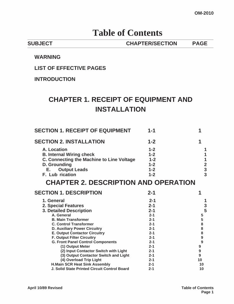
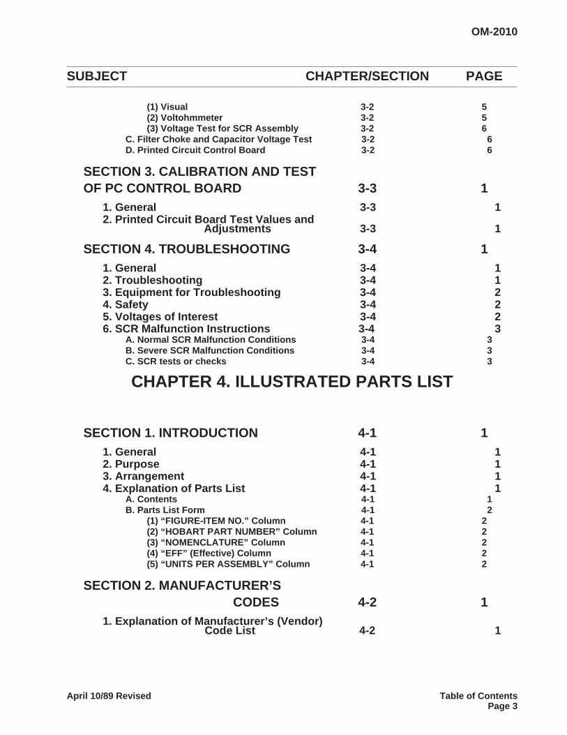
Table of ContentsSUBJECT CHAPTER/SECTION PAGE
WARNING
LIST OF EFFECTIVE PAGES
INTRODUCTION
CHAPTER 1. RECEIPT OF EQUIPMENT ANDINSTALLATION
SECTION 1. RECEIPT OF EQUIPMENT 1-1 1
SECTION 2. INSTALLATION 1-2 1A. Location 1-2 1B. Internal Wiring check 1-2 1C. Connecting the Machine to Line Voltage 1-2 1D. Grounding 1-2 2
E. Output Leads 1-2 3F. Lub rication 1-2 3
CHAPTER 2. DESCRIPTION AND OPERATIONSECTION 1. DESCRIPTION 2-1 1
1. General 2-1 12. Special Features 2-1 33. Detailed Description 2-1 5
A. General 2-1 5B. Main Transformer 2-1 5C. Control Transformer 2-1 8D. Auxiliary Power Circuitry 2-1 8E. Output Contactor Circuitry 2-1 8F. Output Filter Circuitry 2-1 9G. Front Panel Control Components 2-1 9
(1) Output Meter 2-1 9(2) Input Contactor Switch with Light 2-1 9(3) Output Contactor Switch and Light 2-1 9(4) Overload Trip Light 2-1 10
H.Main SCR Heat Sink Assembly 2-1 10J. Solid State Printed Circuit Control Board 2-1 10
OM-2010
April 10/89 Revised Table of ContentsPage 1
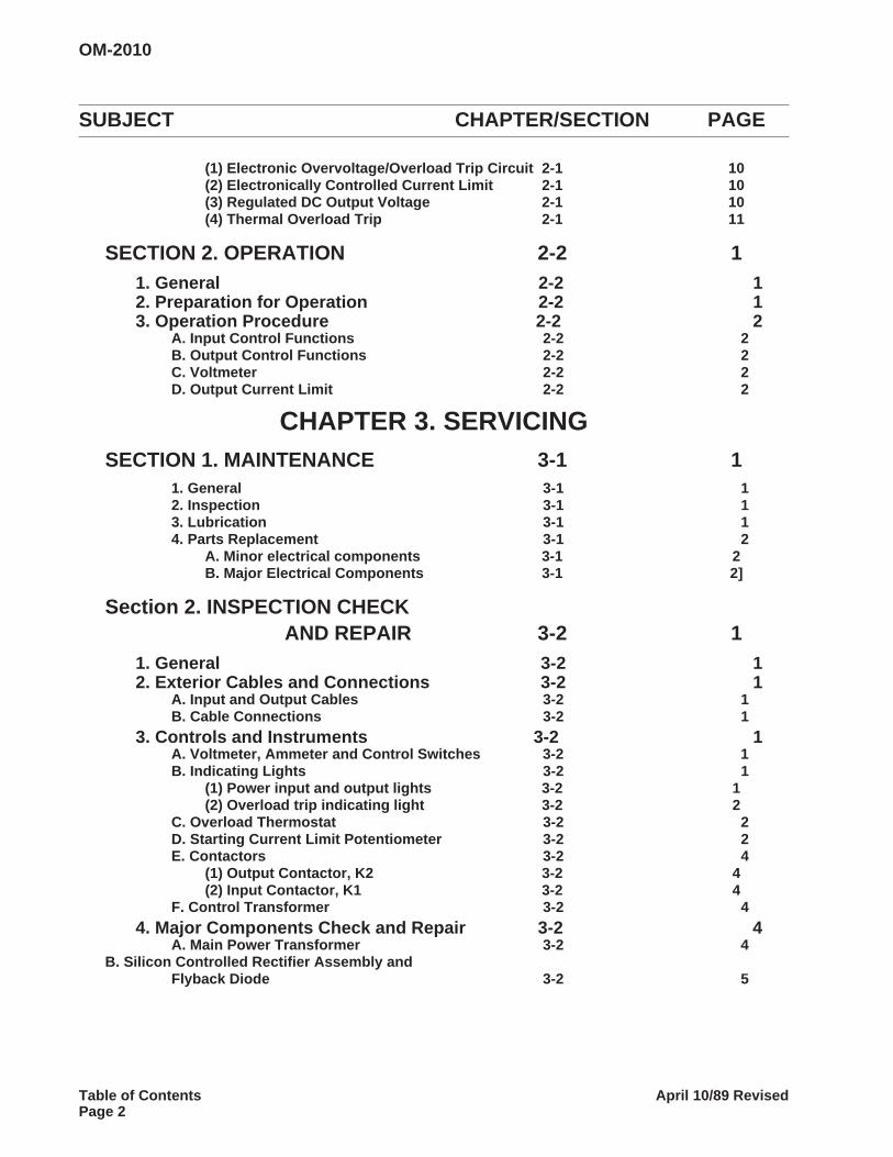
SUBJECT CHAPTER/SECTION PAGE
(1) Electronic Overvoltage/Overload Trip Circuit 2-1 10(2) Electronically Controlled Current Limit 2-1 10(3) Regulated DC Output Voltage 2-1 10(4) Thermal Overload Trip 2-1 11
SECTION 2. OPERATION 2-2 11. General 2-2 12. Preparation for Operation 2-2 13. Operation Procedure 2-2 2
A. Input Control Functions 2-2 2B. Output Control Functions 2-2 2C. Voltmeter 2-2 2D. Output Current Limit 2-2 2
CHAPTER 3. SERVICINGSECTION 1. MAINTENANCE 3-1 1
1. General 3-1 12. Inspection 3-1 13. Lubrication 3-1 14. Parts Replacement 3-1 2
A. Minor electrical components 3-1 2B. Major Electrical Components 3-1 2]
Section 2. INSPECTION CHECKAND REPAIR 3-2 1
1. General 3-2 12. Exterior Cables and Connections 3-2 1
A. Input and Output Cables 3-2 1B. Cable Connections 3-2 1
3. Controls and Instruments 3-2 1A. Voltmeter, Ammeter and Control Switches 3-2 1B. Indicating Lights 3-2 1
(1) Power input and output lights 3-2 1(2) Overload trip indicating light 3-2 2
C. Overload Thermostat 3-2 2D. Starting Current Limit Potentiometer 3-2 2E. Contactors 3-2 4
(1) Output Contactor, K2 3-2 4(2) Input Contactor, K1 3-2 4
F. Control Transformer 3-2 44. Major Components Check and Repair 3-2 4
A. Main Power Transformer 3-2 4B. Silicon Controlled Rectifier Assembly and
Flyback Diode 3-2 5
OM-2010
Table of Contents April 10/89 RevisedPage 2
SUBJECT CHAPTER/SECTION PAGE
(1) Visual 3-2 5(2) Voltohmmeter 3-2 5(3) Voltage Test for SCR Assembly 3-2 6
C. Filter Choke and Capacitor Voltage Test 3-2 6D. Printed Circuit Control Board 3-2 6
SECTION 3. CALIBRATION AND TESTOF PC CONTROL BOARD 3-3 1
1. General 3-3 12. Printed Circuit Board Test Values and
Adjustments 3-3 1
SECTION 4. TROUBLESHOOTING 3-4 11. General 3-4 12. Troubleshooting 3-4 13. Equipment for Troubleshooting 3-4 24. Safety 3-4 25. Voltages of Interest 3-4 26. SCR Malfunction Instructions 3-4 3
A. Normal SCR Malfunction Conditions 3-4 3B. Severe SCR Malfunction Conditions 3-4 3C. SCR tests or checks 3-4 3
CHAPTER 4. ILLUSTRATED PARTS LIST
SECTION 1. INTRODUCTION 4-1 11. General 4-1 12. Purpose 4-1 13. Arrangement 4-1 14. Explanation of Parts List 4-1 1
A. Contents 4-1 1B. Parts List Form 4-1 2
(1) “FIGURE-ITEM NO.” Column 4-1 2(2) “HOBART PART NUMBER” Column 4-1 2(3) “NOMENCLATURE” Column 4-1 2(4) “EFF” (Effective) Column 4-1 2(5) “UNITS PER ASSEMBLY” Column 4-1 2
SECTION 2. MANUFACTURER’SCODES 4-2 1
1. Explanation of Manufacturer’s (Vendor)Code List 4-2 1
OM-2010
April 10/89 Revised Table of ContentsPage 3
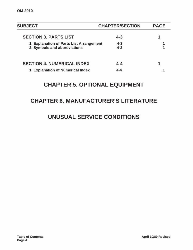
SUBJECT CHAPTER/SECTION PAGE
SECTION 3. PARTS LIST 4-3 11. Explanation of Parts List Arrangement 4-3 12. Symbols and abbreviations 4-3 1
SECTION 4. NUMERICAL INDEX 4-4 11. Explanation of Numerical Index 4-4 1
CHAPTER 5. OPTIONAL EQUIPMENT
CHAPTER 6. MANUFACTURER’S LITERATURE
UNUSUAL SERVICE CONDITIONS
OM-2010
Table of Contents April 10/89 RevisedPage 4
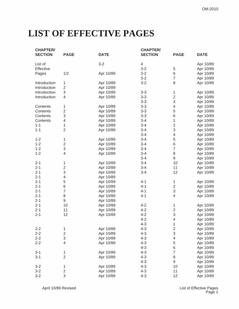
LIST OF EFFECTIVE PAGES
CHAPTER/ CHAPTER/SECTION PAGE DATE SECTION PAGE DATE
List of 3-2 4 Apr 10/89Effective 3-2 5 Apr 10/89Pages 1/2 Apr 10/89 3-2 6 Apr 10/89
3-2 7 Apr 10/89Introduction 1 Apr 10/89 3-2 8 Apr 10/89Introduction 2 Apr 10/89Introduction 3 Apr 10/89 3-3 1 Apr 10/89Introduction 4 Apr 10/89 3-3 2 Apr 10/89
3-3 3 Apr 10/89Contents 1 Apr 10/89 3-3 4 Apr 10/89Contents 2 Apr 10/89 3-3 5 Apr 10/89Contents 3 Apr 10/89 3-3 6 Apr 10/89Contents 4 Apr 10/89 3-4 1 Apr 10/891-1 1 Apr 10/89 3-4 2 Apr 10/891-1 2 Apr 10/89 3-4 3 Apr 10/89
3-4 4 Apr 10/891-2 1 Apr 10/89 3-4 5 Apr 10/891-2 2 Apr 10/89 3-4 6 Apr 10/891-2 3 Apr 10/89 3-4 7 Apr 10/891-2 4 Apr 10/89 3-4 8 Apr 10/89
3-4 9 Apr 10/892-1 1 Apr 10/89 3-4 10 Apr 10/892-1 2 Apr 10/89 3-4 11 Apr 10/892-1 3 Apr 10/89 3-4 12 Apr 10/892-1 4 Apr 10/892-1 5 Apr 10/89 4-1 1 Apr 10/892-1 6 Apr 10/89 4-1 2 Apr 10/892-1 7 Apr 10/89 4-1 3 Apr 10/892-1 8 Apr 10/89 4-1 4 Apr 10/892-1 9 Apr 10/892-1 10 Apr 10/89 4-2 1 Apr 10/892-1 11 Apr 10/89 4-2 2 Apr 10/892-1 12 Apr 10/89 4-2 3 Apr 10/89
4-2 4 Apr 10/894-3 1 Apr 10/89
2-2 1 Apr 10/89 4-3 2 Apr 10/892-2 2 Apr 10/89 4-3 3 Apr 10/892-2 3 Apr 10/89 4-3 4 Apr 10/892-2 4 Apr 10/89 4-3 5 Apr 10/89
4-3 6 Apr 10/893-1 1 Apr 10/89 4-3 7 Apr 10/893-1 2 Apr 10/89 4-3 8 Apr 10/89
4-3 9 Apr 10/893-2 1 Apr 10/89 4-3 10 Apr 10/893-2 2 Apr 10/89 4-3 11 Apr 10/893-2 3 Apr 10/89 4-3 12 Apr 10/89
OM-2010
April 10/89 Revised List of Effective PagesPage 1
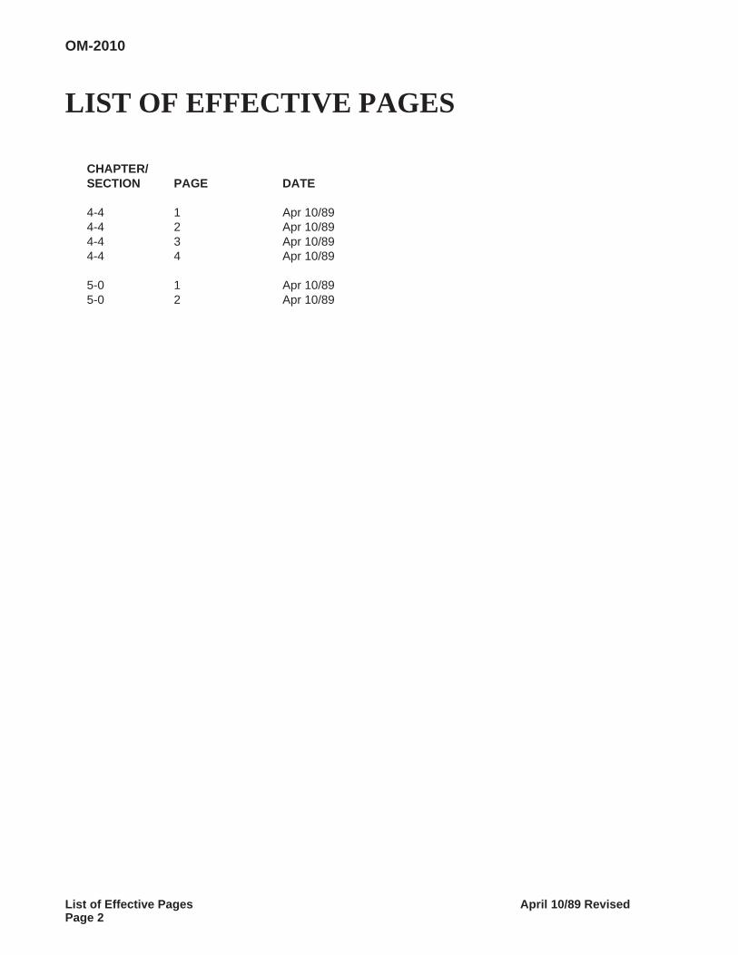
LIST OF EFFECTIVE PAGES
CHAPTER/SECTION PAGE DATE
4-4 1 Apr 10/894-4 2 Apr 10/894-4 3 Apr 10/894-4 4 Apr 10/89
5-0 1 Apr 10/895-0 2 Apr 10/89
OM-2010
List of Effective Pages April 10/89 RevisedPage 2
INTRODUCTION
1. General
This Introduction is intended to give the reader a better understanding of how to use the manual properly.The manual can be very helpful to you if you will READ THIS INTRODUCTION FIRST. READ AND UN-DERSTAND THE MANUAL BEFORE ATTEMPTING TO OPERATE, INSTALL, OR REPAIR THISEQUIPMENT.
2. Scope
The manual covers a solid state controlled transformer-rectifier, 600 A DC ground power unit having theSpecification Numbers listed. It gives a detailed description of the equipment and includes information cov-ering operation, installation, troubleshooting and repair.
3. Purpose
The manual’s purpose is to provide information and instructions to experienced operators, electricians,and repairmen who have never seen or operated this equipment. It is the intent of the manual to guideand assist operators and maintenance personnel in the proper use and maintenance of the equipment.
4. Contents
Immediately following the Introduction is a List of Effective Pages which lists each page in the manual byits Chapter/Section, and page number. Directly opposite each page number listing is a date which indi-cates whether the page is original or revised.
A complete Table of Contents appears next in sequence. It contains a list of all Chapters, Sections, andthe principal paragraph titles within each Section. The location of each listing is identified by Chapter/Sec-tion and page number. A complete list of illustrations with their location is located at the end of the Tableof Contents.
The main text of the manual is divided into five Chapters as follows:
Chapter 1. Receipt and Installation Instructions
Chapter 2. Description and Operation
Chapter 3. Servicing
Chapter 4. Illustrated Parts List with Index
Chapter 5. Optional Equipment
Chapter 6. Manufacturer’s Literature
Each Chapter is divided into as many Sections as necessary. Sections are always referred to by a combi-nation Chapter/Section number. Example, 2-3 refers to Chapter 2, Section 3.
OM-2010
April 10/89 Revised IntroductionPage 1
5. Format
A. Paragraphing and Outlining
The material within each Section is divided into main subjects with applicable paragraph headingsand sub-headings as required. This method not only helps keep information closely knit, but providesa means of identifying material for reference purposes. For example, a portion of the Description Sec-tion might logically follow this arrangement and paragraphing:
1. Control A. Interior Panel
(1) Protective devices
(a) Overload relay
(2) Contactors
B. Page Numbering
Page numbers do not run consecutively throughout the manual. Each page is identified by the Chap-ter/Section number in which it appears, and by a page number within the Chapter/Section. Therefore,the first page in each Section is page 1. These identifying numbers appear in the lower, outside cor-ner of each page. Each page also bears a date located in the corner opposite the page number. Thisdate is either that of original issue, or of the latest revision. Any revision to the original text is identifiedby a heavy black line in the left-hand margin. Illustrations follow a numbering system similar to pagenumbering. The first Figure in each Section is Figure 1.
6. How to Use the Manual
A. General
This manual follows the format, rules and style proposed by, and generally accepted by members ofthe Air Transport Association. Insofar as possible, information is grouped to help the user locate itquickly. All tables, charts, diagrams, etc., as well as illustrations, are identified by Figure Number (i.e.,Fig. 2) to avoid confusion.
B.How to Locate Information
Even if you have read the manual completely and thoroughly, the easiest and quickest way to locateinformation is by using the Table of Contents. Look for new and added information at the end of thesection in which it is normally found.
(1) Table of Contents
The complete Table of Contents is relatively short. Even if the user has no idea where a certainbit of information is located, the general location can be quickly found by running through the Ta-ble of Contents. For example, some adjustment information is needed. A quick look at the Tableof Contents indicates that Adjustment/Test information is located in 3-3 (Chapter 3, Section 3).
OM-2010
Introduction April 10/89 RevisedPage 2
(2) List of Illustrations
A complete list of Illustrations follows the Table of Contents and includes the title, figure number,and Chapter/Section, with page number location of all illustrations contained in the manual. Lo-cate the appropriate title in the List of Illustrations, then turn to the Chapter/Section and pagenumber indicated. A complete set of electrical schematic and connection diagrams is included inChapter 5.
(3) References
To avoid repetition and lengthy explanations, references to other material are used throughoutthe manual. Both material in the text and illustrations may be referred to in order to clarify or ex-pand information and instructions. Portions of the text are referred to by identifying the paragraphin which referenced material may be found. A reference to other material would be in order hereby referring to paragraphing information contained in paragraph 5, A above. When referenced ma-terial is located in the same Chapter/Section as the reference, only the paragraph identification isgiven.
Example:
(Ref. Para. 1, A) means the material is to be found in paragraph 1, A, of the same Chap-ter/Section.
When referenced material is located in another Chapter/Section, both the Chapter/Sectionnumber and the paragraph identification are given.
Example:
(Ref. 1-2, Para. 1, A) means that the referenced material is located in Chapter/Section 1-2,and identified by paragraph 1, A.
Components shown in illustrations and illustrations themselves are referenced in a similar man-ner. When this type reference is made, the item number of the part and the Figure number inwhich it appears are given.
Example:
(Ref. 2, Fig. 3) refers to item number 2 which appears in illustration Figure 3 of the sameChapter/Section.
When the referenced Figure appears in another Chapter/Section, the reference will include theChapter/Section number.
OM-2010
April 10/89 Revised IntroductionPage 3
Example:
(Ref. 2-3; 1, Fig. 4) tells the user to refer to Chapter/Section 2-3, and to see item 1, in Figure4.
Once a Figure number reference has been established for a series of instructional steps, the Fig-ure number is not repeated. Only the item numbers of parts involved are referenced.
For example, an instruction might appear like this: “Loosen screw (2, Fig. 6), slide out connec-tor (4), and remove brush (6)”.
When an item is referenced without a figure number, it will always apply to the last precedingFigure number mentioned in the text.
NOTE 1: The word See may appear in some references, as (See Fig. 2). It means exactly the same thingas Ref., however, its usage seems a little more direct and definite.
NOTE 2: When an “output cable” is mentioned in the manual, it refers to a large cable used to carryoutput current. A special connector for the two output leads and the ground lead may be required whendelivering power directly to an aircraft.
7. SERVICE
If you have any questions concerning your Hobart Power Systems Division equipment, please contactour Service Department by mail, telephone or FAX.
Write: Hobart Brothers CompanyPower Systems Group
Service DepartmentTroy, Ohio 45373
U.S.A.
Call: Area Code (513) 339-5060
FAX: 513-339-4219
OM-2010
Introduction April 10/89 RevisedPage 4
CHAPTER 1. RECEIPT OF EQUIPMENTAND INSTALLATION
SECTION 1. RECEIPT OF EQUIPMENT
Check the equipment received against the Hobart Brothers Company invoice to make certain that theshipment is complete and undamaged. If the equipment has been damaged in transit, notify the carrier(railroad, trucking company, etc.) at once and file a claim for damages. If you require assistance with adamage claim, furnish Hobart Brothers Company with full information about the claim. If the shipment is inerror, contact Order Department, Hobart Brothers Company, Power Systems Division, Troy, Ohio 45373.
Give the MODEL, SPECIFICATION , and SERIAL numbers of the equipment, and a full description of theparts in error. Refer to the title of this manual for a listing of the specification numbers this manual describes.An identification and rating nameplate is normally located on the power supply front panel for yourconvenience. If the rated input or output voltages do not agree with your requirements, contact the orderdepartment for instructions or corrective action.
Generally, it is good practice to move the equipment to the site of installation before uncrating or unpacking .Take care to avoid damage to the equipment if bars, hammers, etc., are used. Lifting eyes which extendthrough the top of the cabinet have been provided to facilitate handling with a crane or hoist. Be certain thecrane or hoist is adequate for the task.
Best results will be obtained with this equipment ONLY if the responsible operating personnel have access tothis manual, and are familiar with these instructions. Additional copies may be obtained at a small cost percopy by writing to: Hobart Brothers Company, Power Systems Division, Troy, Ohio Supply the owner’smanual no. (OM-2010) plus the model, specification, and serial numbers of your equipment.
OM-2010
April 10/89 Revised 1-1Page 1
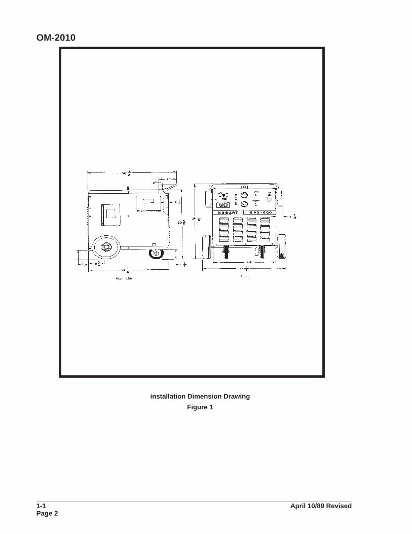
installation Dimension Drawing
Figure 1
OM-2010
1-1 April 10/89 RevisedPage 2
SECTION 2. INSTALLATION
A. Location
For best operating characteristics and longest unit life, select an installation site that is not exposed tohigh humidity, dust, high ambient temperature, flooding, or corrosive agents. Moisture can condense onelectrical components, causing corrosion or shorting of circuits. Dirt on components helps retain this mois-ture in addition to providing a conducting material.
Adequate air circulation is needed at all times in order to assure proper operation. Provide a minimum of12 inches (305mm) of free air space at both front and rear of the unit. Make sure that the ventilator open-ings are not obstructed.
B. Internal Wiring check
Refer to the product identification plate (nameplate) on the machine’s control panel to determine thepower input voltages and frequency at which it will be operated.
WARNING: ELECTRIC SHOCK CAN KILL. OPEN THE DISCONNECT SWITCH,OR BREAKER, AND DETERMINE THAT NO VOLTAGE IS PRESENT, BEFORECONNECTING WIRES BETWEEN THE INPUT SERVICE AND POWER SUPPLYOR WORKING ON THE POWER SUPPLY.
CAUTION: RECONNECTION OF CONTROL TRANSFORMER AS WELL AS MAIN INPUT CON-NECTION PANEL MUST BE MADE WHEN CHANGING RATED INPUT VOLTAGE. SEE CHANGE-OVER DIAGRAM.
Remove cabinet top for access to LINE VOLTAGE MAIN CHANGEOVER circuitry. Check line voltageconnections against instructions on the VOLTAGE CHANGEOVER DIAGRAM supplied with this manual.If necessary, rearrange internal wiring and/or link connections to agree with the requirements for your in-put.
C. Connecting the Machine to Line Voltage
The input power should be connected to the input terminals on the lifting baffle via a suitable disconnect-ing means furnished by the user. Select the proper sized knock-out hole provided in the rear panel of themachine to allow for the entry of the input conductors. Be certain the cable inside the power supply willnot contact the fan or hot parts. The lower holes may give a bit less weather leakage.
CAUTION: THE METHOD OF INSTALLATION, CONDUCTOR SIZE, AND OVERCURRENT PRO-TECTION SHALL CONFORM TO THE REQUIREMENTS OF THE LOCAL ELECTRICAL CODE,THE NATIONAL ELECTRICAL CODE, OR OTHER NATIONAL CODES, AS APPLICABLE. ALL IN-STALLATION WIRING AND MACHINE RECONNECTION SHALL BE DONE BY QUALIFIED PER-SONS.
OM-2010
April 10/89 Revised 1-2Page 1
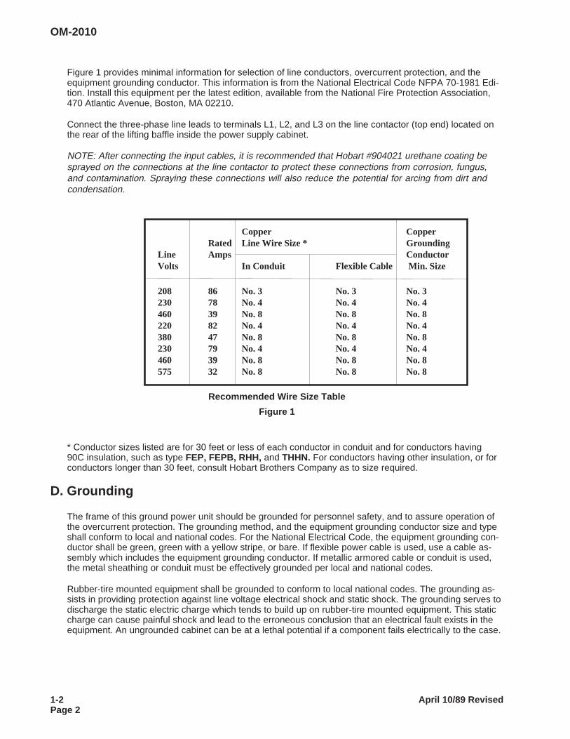
Figure 1 provides minimal information for selection of line conductors, overcurrent protection, and theequipment grounding conductor. This information is from the National Electrical Code NFPA 70-1981 Edi-tion. Install this equipment per the latest edition, available from the National Fire Protection Association,470 Atlantic Avenue, Boston, MA 02210.
Connect the three-phase line leads to terminals L1, L2, and L3 on the line contactor (top end) located onthe rear of the lifting baffle inside the power supply cabinet.
NOTE: After connecting the input cables, it is recommended that Hobart #904021 urethane coating besprayed on the connections at the line contactor to protect these connections from corrosion, fungus,and contamination. Spraying these connections will also reduce the potential for arcing from dirt andcondensation.
Copper CopperRated Line Wire Size * Grounding
Line Amps ConductorVolts In Conduit Flexible Cable Min. Size
208 86 No. 3 No. 3 No. 3230 78 No. 4 No. 4 No. 4460 39 No. 8 No. 8 No. 8220 82 No. 4 No. 4 No. 4380 47 No. 8 No. 8 No. 8230 79 No. 4 No. 4 No. 4460 39 No. 8 No. 8 No. 8575 32 No. 8 No. 8 No. 8
Recommended Wire Size Table
Figure 1
* Conductor sizes listed are for 30 feet or less of each conductor in conduit and for conductors having90C insulation, such as type FEP, FEPB, RHH, and THHN. For conductors having other insulation, or forconductors longer than 30 feet, consult Hobart Brothers Company as to size required.
D. Grounding
The frame of this ground power unit should be grounded for personnel safety, and to assure operation ofthe overcurrent protection. The grounding method, and the equipment grounding conductor size and typeshall conform to local and national codes. For the National Electrical Code, the equipment grounding con-ductor shall be green, green with a yellow stripe, or bare. If flexible power cable is used, use a cable as-sembly which includes the equipment grounding conductor. If metallic armored cable or conduit is used,the metal sheathing or conduit must be effectively grounded per local and national codes.
Rubber-tire mounted equipment shall be grounded to conform to local national codes. The grounding as-sists in providing protection against line voltage electrical shock and static shock. The grounding serves todischarge the static electric charge which tends to build up on rubber-tire mounted equipment. This staticcharge can cause painful shock and lead to the erroneous conclusion that an electrical fault exists in theequipment. An ungrounded cabinet can be at a lethal potential if a component fails electrically to the case.
OM-2010
1-2 April 10/89 RevisedPage 2
If a system ground is not available, consult the electrical code enforcement body for instructions. Theground power unit should be connected per your electrical code to an adequate driven ground rod or to awater pipe that enters the ground not more than 10 feet (3 meters) from the machine.
The equipment grounding conductor size listed in Fig. 1 is a guide if no local or national code is applicable.
Attach the equipment grounding block conductor to the stud provided adjacent to the fuse block. Deter-mine that the ground wire size is adequate before the machine is used.
CAUTION: FOR SAFETY AND TO ASSURE ADEQUATE VENTILATION, BE SURE TO RE-PLACE CABINET TOP.
E. Outpu t Leads
Use your applicable electrical code to determine the minimum size output cable you need. If the cable volt-age drop is too large with the minimum size cable, use a larger size cable. For example, the 90 C rated in-sulation, 4/0 cable in a 40 C ambient needed for 400 A DC may have to be larger for carrying thatamperage over 200 feet with less than 4.5 Volts cable drop.
OM-2010
Apri l 10/89 Revised 1-2Page 3

This page intentionally left blank.
OM-2010
1-2 April 10/89 RevisedPage 4
CHAPTER 2. DESCRIPTION ANDOPERATION
SECTION 1. DESCRIPTION
1. General
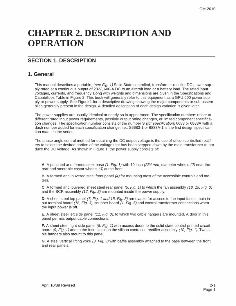
This manual describes a portable, (see Fig. 1) Solid State controlled, transformer-rectifier DC power sup-ply rated at a continuous output of 28-V, 600-A DC to an aircraft load or a battery load. The rated inputvoltages, currents, and frequency along with weights and dimensions are given in the Specifications andCapabilities Table in Figure 2. This book will generally refer to this equipment as a GPU-600 power sup-ply or power supply. See Figure 1 for a descriptive drawing showing the major components or sub-assem-blies generally present in the design. A detailed description of each design variation is given later.
The power supplies are usually identical or nearly so in appearance. The specification numbers relate todifferent rated input power requirements, possible output rating changes, or limited component specifica-tion changes. The specification number consists of the number S (for specification) 6683 or 6883A with adash number added for each specification change, i.e., S6683-1 or 6883A-1 is the first design specifica-tion made in the series.
The phase angle control method for obtaining the DC output voltage is the use of silicon controlled rectifi-ers to select the desired portion of the voltage that has been stepped down by the main transformer to pro-duce the DC voltage. As shown in Figure 1, the power supply consists of:
A. A punched and formed steel base (1, Fig. 1) with 10 inch (254 mm) diameter wheels (2) near therear and steerable castor wheels (3) at the front.
B. A formed and louvered steel front panel (4) for mounting most of the accessible controls and me-ters.
C. A formed and louvered sheet steel rear panel (5, Fig. 1) to which the fan assembly (18, 19, Fig. 3)and the SCR assembly (17, Fig. 3) are mounted inside the power supply.
D. A sheet steel top panel (7, Fig. 1 and 15, Fig. 3) removable for access to the input fuses, main in-put terminal board (16, Fig. 3), snubber board (1, Fig. 5) and control transformer connections whenthe input power is off.
E. A sheet steel left side panel (11, Fig. 3), to which two cable hangers are mounted. A door in thispanel permits output cable connections.
F. A sheet steel right side panel (8, Fig. 1) with access doors to the solid state control printed circuitboard (9, Fig. 1) and to the fuse block on the silicon controlled rectifier assembly (10, Fig. 1). Two ca-ble hangers also mount to this panel.
G. A steel vertical lifting yoke (3, Fig. 3) with baffle assembly attached to the base between the frontand rear panels.
OM-2010
April 10/89 Revised 2-1Page 1
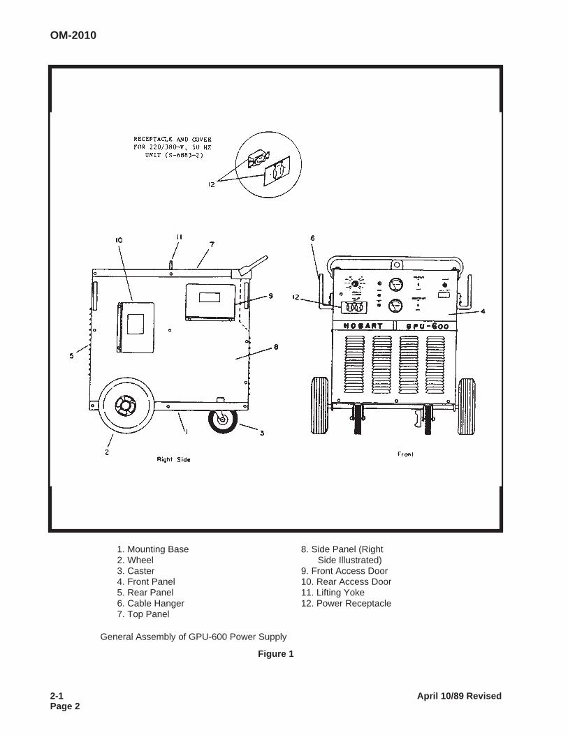
1. Mounting Base 8. Side Panel (Right2. Wheel Side Illustrated)3. Caster 9. Front Access Door4. Front Panel 10. Rear Access Door5. Rear Panel 11. Lifting Yoke6. Cable Hanger 12. Power Receptacle7. Top Panel
General Assembly of GPU-600 Power Supply
Figure 1
OM-2010
2-1 April 10/89 RevisedPage 2

H. Various internal components such as the preload resistors (6, Fig. 3), main transformer (1, Fig. 3),filter capacitors (4, Fig. 3) with the bus bar (5, Fig. 3) at the front, filter reactor (7, Fig. 3), two (8, 9,Fig. 3) output contactor, control transformer (10, Fig. 3), and printed circuit control board (13, Fig. 3),input contactor (14, Fig. 3), etc.
CAUTION: CAPACITOR CHARGE CAN INJURE! ALLOW CAPACITORS TO DISCHARGE ANDVERIFY CAPACITOR DISCHARGE WITH VOLTMETER BEFORE TOUCHING THE CAPACITORCIRCUITRY.
2. Special Features
This DC ground power supply has the following special features which may be described more fully, if re-quired, in the detailed description:
A. Output Ammeter, M1, (2, Fig. 4) with a 0-2000 A DC scale for reading the DC output amperes. Thesignal is provided by R11 meter shunt (20, Fig. 3).
B. Output Voltmeter, M2, (3, Fig. 4) having a 0 to 50 V DC scale reading the DC output voltage.
C. Input contactor, (14, Fig. 3) with amber input contactor on-off light (12, Fig. 4)
D. 28-V DC contactor (8, 9, Fig. 3) with green output contactor on-off light (13, Fig. 4).
E. Solid state closed loop feedback output voltage control to compensate for brown-outs and load re-lated power supply voltage droop.
F. Output overvoltage (31.5 V DC) and overcurrent turn off circuitry and turn on DS2 trip light.
G. Adjustable solid state output limit circuitry. The customer selects the momentary output limit in the250 to 2000 A DC range by adjusting the R13 starting current potentiometer (8, Fig. 4). A preset volt-age slope circuit causes a 25 percent drop in output voltage from 600 A DC to 1600 A DC output cur-rent.
CAUTION: EXCESSIVE CHARGING CURRENT CAN DAMAGE SOME TYPES OF BATTERIESAND SOME OTHER LOADS. IF THE 250 A DC “STARTING SURGE” LEVEL IS TOO HIGH FORYOUR PARTICULAR LOAD, CONTACT THE MANUFACTURER FOR RECOMMENDATIONS.
H. Auxiliary power receptacle (5, Fig. 4) with weather protection cover (7, Fig. 4) On the 60-Hz model,this is a duplex receptacle rated at 115 V AC, 9-amperes, single phase. On the 50-Hz model, this is asingle output rated at 220 V AC, 15-amperes, single phase.
J. Thermal overload thermostat (3, Fig. 5) which turns off the output voltage when the SCR heatsinkoverheats.
OM-2010
April 10/89 Revised 2-1Page 3
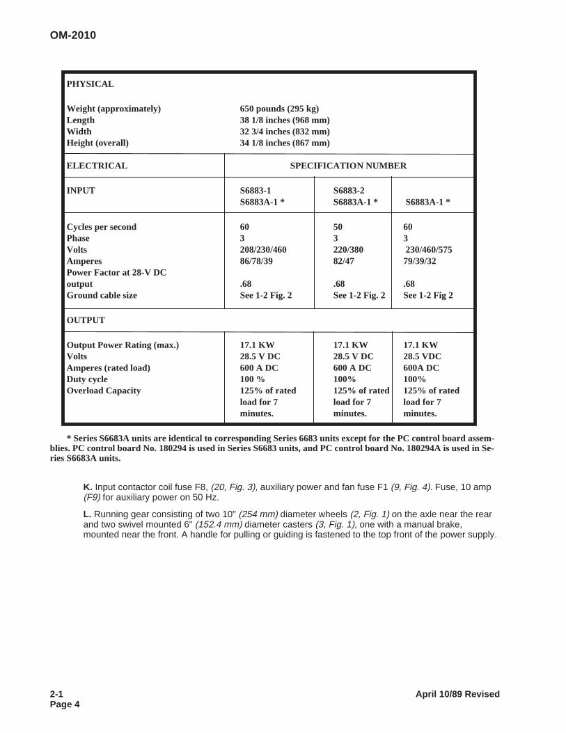
PHYSICAL
Weight (approximately) 650 pounds (295 kg)Length 38 1/8 inches (968 mm)Width 32 3/4 inches (832 mm)Height (overall) 34 1/8 inches (867 mm)
ELECTRICAL SPECIFICATION NUMBER
INPUT S6883-1 S6883-2S6883A-1 * S6883A-1 * S6883A-1 *
Cycles per second 60 50 60Phase 3 3 3Volts 208/230/460 220/380 230/460/575Amperes 86/78/39 82/47 79/39/32Power Factor at 28-V DCoutput .68 .68 .68Ground cable size See 1-2 Fig. 2 See 1-2 Fig. 2 See 1-2 Fig 2
OUTPUT
Output Power Rating (max.) 17.1 KW 17.1 KW 17.1 KWVolts 28.5 V DC 28.5 V DC 28.5 VDCAmperes (rated load) 600 A DC 600 A DC 600A DCDuty cycle 100 % 100% 100%Overload Capacity 125% of rated 125% of rated 125% of rated
load for 7 load for 7 load for 7minutes. minutes. minutes.
* Series S6683A units are identical to corresponding Series 6683 units except for the PC control board assem-blies. PC control board No. 180294 is used in Series S6683 units, and PC control board No. 180294A is used in Se-ries S6683A units.
K. Input contactor coil fuse F8, (20, Fig. 3), auxiliary power and fan fuse F1 (9, Fig. 4). Fuse, 10 amp(F9) for auxiliary power on 50 Hz.
L. Running gear consisting of two 10" (254 mm) diameter wheels (2, Fig. 1) on the axle near the rearand two swivel mounted 6" (152.4 mm) diameter casters (3, Fig. 1), one with a manual brake,mounted near the front. A handle for pulling or guiding is fastened to the top front of the power supply.
OM-2010
2-1 April 10/89 RevisedPage 4
3. Detailed Description
A. General
A detailed description of the parts used to build the power supply is given below. If a description ap-plies only to power supplies having a particular specification number, reference to that specificationwill be made. The specification number and equipment rating information is provided on the name-plate located on the power supply front panel just above the manufacturers name. Be certain that thespecification number and rating is proper for your input power rating. Also be sure that your outputvoltage setting is properly rated for your load. Refer also to Figure 2 of this chapter for the tabulationof rated values for the specifications listed.
This power supply utilizes solid state devices to control the output of the main transformer by delayingthe turn on time of the main siliconcontrolled rectifier to that required to give the desired power supplyoutput voltage. This control method is called SCR phase angle control.
The turn on delay after the voltage input to the SCR devices is quite similar to a phase shift. Gener-ally, the longer the turn-on delay (i.e., lower output voltage) the lower the power supply input powerfactor. The printed circuit board has various data sent to it from sensors and/or points in the powersupply. These data are compared with the commands that the user has established so that instruc-tions to correct any abnormality in output can be automatically provided.
B. Main Transformer (1, Fig. 3)
The main power transformer is a forced air cooled, core-type, 3 phase unit that reduces the rated in-put voltage or voltages to a voltage somewhat higher than the maximum rated output voltage. The ex-tra voltage for the output provides a reserve capability to compensate for undervoltage on the inputcircuit, for the higher IR voltage drop found as the transformer, cables and other components heat upwith load and ambient temperature rises.
OM-2010
April 10/89 Revised 2-1Page 5
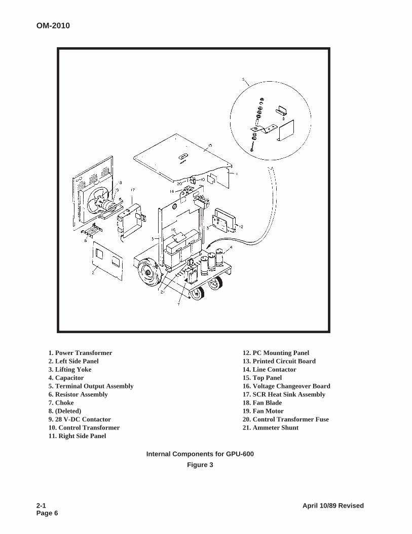
1. Power Transformer 12. PC Mounting Panel2. Left Side Panel 13. Printed Circuit Board3. Lifting Yoke 14. Line Contactor4. Capacitor 15. Top Panel5. Terminal Output Assembly 16. Voltage Changeover Board6. Resistor Assembly 17. SCR Heat Sink Assembly7. Choke 18. Fan Blade8. (Deleted) 19. Fan Motor9. 28 V-DC Contactor 20. Control Transformer Fuse10. Control Transformer 21. Ammeter Shunt11. Right Side Panel
Internal Components for GPU-600
Figure 3
OM-2010
2-1 April 10/89 RevisedPage 6
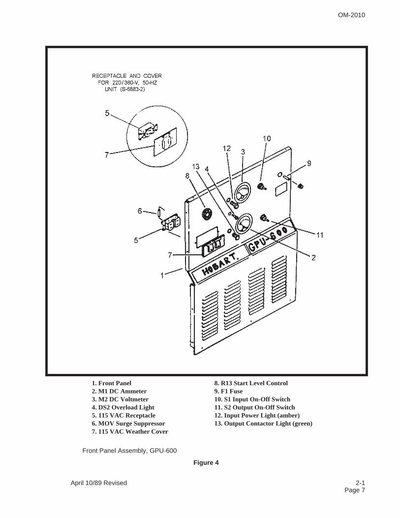
1. Front Panel 8. R13 Start Level Control2. M1 DC Ammeter 9. F1 Fuse3. M2 DC Voltmeter 10. S1 Input On-Off Switch4. DS2 Overload Light 11. S2 Output On-Off Switch5. 115 VAC Receptacle 12. Input Power Light (amber)6. MOV Surge Suppressor 13. Output Contactor Light (green)7. 115 VAC Weather Cover
Front Panel Assembly, GPU-600
Figure 4
OM-2010
April 10/89 Revised 2-1Page 7
The main transformer of the 208/230/460-V power supply (Spec 6683-1 or 6883A-1) has a winding toprovide the 115-V AC for the auxiliary power receptacle and fan motor. The main transformer has acenter tapped coil on each phase that provides six sensing or synchronizing voltage signals to thesolid state printed circuit control board (13, Fig. 3).
The main transformer for the 220/380-V power supply (Spec 6683-2 or 6883A -2) has a 220-V ACwinding for its auxiliary power receptacle and a 110-V AC winding for the fan motor. Be certain to fol-low the changeover diagram for both the main transformer and the control transformer (10, Fig. 3) forthe input voltage you have available.
CAUTION: IMPROPER CONNECTIONS WILL CAUSE DAMAGE. CONTACT FACTORY IF YOUREQUIPMENT SPECIFICATION INFORMATION AND/OR VOLTAGE CHANGEOVER DIAGRAMDOES NOT AGREE WITH YOUR RATED 3 PHASE INPUT VOLTAGE.
C. Control Transformer (10, Fig. 3)
The small control transformer located on the rear of the inside baffle (3, Fig. 3) or lifting eye plate pro-vides 115 V AC to the K1 (14, Fig. 3) input contactor coil, input contactor light A (12, Fig. 4), and S1(11, Fig. 4) input contactor switch via the half amp F8 contactor fuse (20, Fig. 3) on the control trans-former. This transformer does not provide the 9A, 115 V AC auxiliary power.
WARNING: ELECTRIC SHOCK CAN KILL! DISCONNECT INPUT POWER ATSOURCE TO REMOVE VOLTAGE TO CONTROL TRANSFORMER AND INPUTFUSES AND CONTACTOR.
D. Auxiliary Power Circuitry
The 115 V AC single phase auxiliary power receptacle (5, Fig. 4) has the same frequency as the pri-mary input voltage. It is protected by the F1 fuse (9, Fig. 4) located on the power supply front panel,typically, 15 Amperes. The auxiliary power circuitry is turned off whenever the primary contactor isopen or off. The auxiliary power winding is typically located on the middle leg (B phase) of the maintransformer. It provides power to the duplex 115 V AC receptacle (5, Fig. 4) and to the fan motor.
A “MOV” voltage surge suppressor, RV (6, Fig. 4), is installed across the 115 V AC receptacle termi-nals to reduce voltage surge problems to the load equipment and the power source.
E. Output Contactor Circuitry
Output contactor K2 (9, Fig. 3) is operated by the output contactor ON-OFF switch S2 (11, Fig. 4).Placing this switch momentarily in the UP (spring-loaded) position turns the output contactor ON, andplacing it in the DOWN position turns the output contactor OFF.
The positive output lead is to be connected to the positive output terminal of the K2 contactor. Thenegative output lead is to be connected to the negative bus bar (5, Fig. 3) of the C15-C17 output filtercapacitor bank (4, Fig. 3). A small notch has been made in the bottom of the right and left side panelsto allow for the output cable assembly to pass out either side.
OM-2010
2-1 April 10/89 RevisedPage 8
F. Output Filter Circuitry
The DC output voltage is smoothed (filtered) by an L-C filter made up of L1 iron core reactor (7, Fig.3) carrying the output current to the load and the ripple current to the C15, C16, C17 ripple bypass ca-pacitors (4, Fig. 3) in parallel with the load terminals. The R2, R3, R4 bypass resistors (6, Fig. 3) pro-vide both a preload to the SCR devices (2, Fig. 5) and a safety discharge circuit for quicklydischarging the filter capacitors whenever the power supply is turned off.
CAUTION: CAPACITOR CHARGE CAN INJURE. BE SURE CAPACITORS ARE DISCHARGEDBEFORE TOUCHING.
The CR7 flyback diode (6, Fig. 5) acts to facilitate discharge of the output filter circuitry as well as toprotect the main SCR rectifier assembly from damaging reverse voltage spikes.
G. Front Panel Control Components (See Fig. 4)
(1) Output Meter
The power supply is typically supplied with a 0 to 2000 Amp scale DC ammeter M1 (21, Fig. 4)which measures the millivolt drop across the R11 meter shunt (20, Fig. 3) that corresponds to thescale calibration. The scale range is so much more than the rated output because the R13 start-ing current potentiometer (8, Fig. 4) can select any initial or starting current from 250 amperes toa maximum of 2000 amperes. The M2 output voltmeter (16, Fig. 4) measures the DC output volt-age across the main filter capacitors.
The scale typically has a 50 V DC maximum reading. It should be emphasized that the R12 con-trol feedback shunt (21, Fig. 3) is not to be used for the meter shunt. This separation provides bet-ter control integrity.
(2) Input Contactor Switch with Light
The S1 input contactor switch (10, Fig. 4) controls the 115 V AC contactor pickup voltage sup-plied by the control transformer via the F8 fuse. The amber input contactor light (12, Fig. 4) glowswhenever voltage is applied to the input contactor coil. The input contactor applies the rated inputvoltage to main changeover board (16, Fig. 3).
WARNING: ELECTRIC SHOCK CAN KILL! DISCONNECT THE INPUT POWERFROM THE POWER SUPPLY BEFORE TOUCHING INTERNAL PARTS. THE IN-PUT CONTACTOR DOES NOT REMOVE ALL INPUT POWER FROM THEUNIT. BE SURE ALL CAPACITORS HAVE DISCHARGED BEFORE TOUCHINGTHE COMPONENTS.
(3) Output Contactor Switch and Light
The S2 output contactor close on-off switch (11, Fig. 4) has a spring loaded up position for theclose mode, a middle position for “on” mode, and a bottom position for the “off” mode. The greenoutput contactor “on” light (13, Fig. 4) glows for all the positions except “off”.
OM-2010
April 10/89 Revised 2-1Page 9
(4) Overload Trip Light (4, Fig. 4)
The overload trip light glows whenever the solid state printed circuit board turns off the power sup-ply output due to output voltage exceeding 31.5 V DC, output current surge exceeding 2200-ADC.
H.Main SCR Heat Sink Assembly (See Fig. 5)
The main SCR heat sink assembly is mounted on the front of the rear panel. It surrounds the 115 VAC cooling fan assembly for optimum cooling efficiency. The SCR heat sink (2, Fig. 5) consists of aformed aluminum heat sink with 6 “hockey puck” silicon controlled rectifiers held by 6 insulated com-pression spring assemblies held against it by 6 U-shaped aluminum heat sinks for the “hockey puck”device cooling, two snubber pc board assemblies for SCR gate signal control and protection (1, Fig.5), the associated insulators, thermostats and hardware.
The solid state printed circuit board (13, Fig. 3) described later provides a properly timed and se-quenced turn on signal to the silicon controlled rectifiers that must conduct to provide the desired out-put. If the output voltage is too high or if the output current is above the limit set by controls such asthe R13 starting potentiometer, the “pcb” control delays the SCR turn-on signal to allow less SCR de-vice conduction time for a correspondly lower output. Conversely, if the output voltage is too low, theSCR turn-on signal is delivered earlier in the possible conduction time for each SCR thereby allowingmore power to be supplied because of the longer conduction time. Proper operation of the SCR de-vices requires phase sequence and presence of all 6 voltage sensing signals, proper phase se-quence and presence of the output voltage to the SCR devices and the proper magnitude andsequence of the SCR turn-on signal to the SCR gate leads.
J. Solid State Printed Circuit Control Board (13, Fig. 3)
The printed circuit board is located in a steel box behind the front access door on the power supplyright side panel (2, Fig. 3). This large printed circuit board is the “brains” or electronic control for thefollowing functions:
(1) Electronic Overvoltage/Overload Trip Circuit
The “pc board” trips the power supply off and turns on DS-2 red overload trip light (4, Fig. 4) onthe front panel if more than 31.5 V DC or 2200 A overload exists. To reset, correct the cause ofthe condition and then turn the input switch off and back on.
(2) Electronically Controlled Current Limit
The starting current or output surge current is selected by adjusting R13 starting current control(8, Fig. 4) on the front panel from the minimum 250 A DC to the maximum 2000 A DC.
CAUTION: EXCESS STARTING CURRENT MAY CAUSE DAMAGE TO LOAD, BLOW FUSES ORDAMAGE POWER SUPPLY. CONTACT FACTORY IF YOU REQUIRE A CURRENT LIMIT LOWERTHAN THE 250 A DC STANDARD MINIMUM LIMIT.
(3) Regulated DC Output Voltage
The voltage value is continuously compared to the actual output. If adequate input voltage exists,deviation from the desired voltage output is corrected by the change in SCR conduction time setby the printed circuit board firing pulse output. This corrective action is done quickly because thecontrol is done electronically with only limited stored energy in the circuitry. Typical response timeis about 25 milliseconds.
OM-2010
2-1 April 10/89 RevisedPage 10
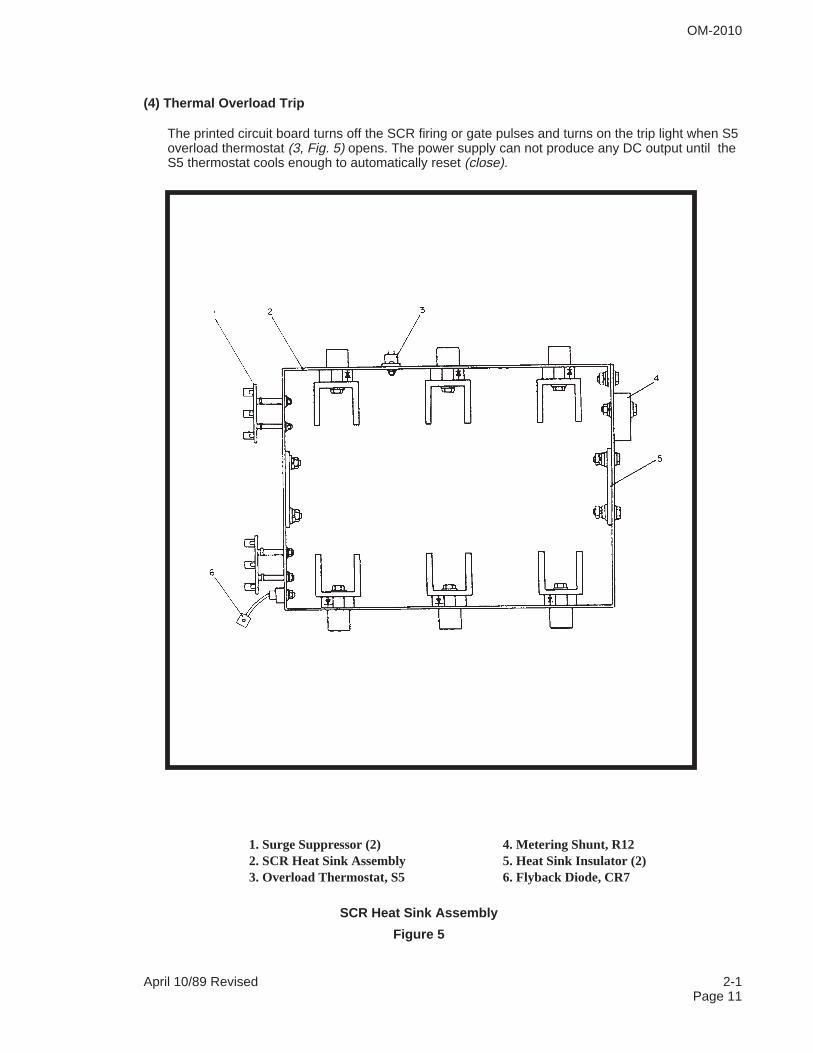
(4) Thermal Overload Trip
The printed circuit board turns off the SCR firing or gate pulses and turns on the trip light when S5overload thermostat (3, Fig. 5) opens. The power supply can not produce any DC output until theS5 thermostat cools enough to automatically reset (close).
1. Surge Suppressor (2) 4. Metering Shunt, R122. SCR Heat Sink Assembly 5. Heat Sink Insulator (2)3. Overload Thermostat, S5 6. Flyback Diode, CR7
SCR Heat Sink Assembly
Figure 5
OM-2010
April 10/89 Revised 2-1Page 11

This page intentionally left blank
OM-2010
2-1 April 10/89 RevisedPage 12
CHAPTER 2. DESCRIPTION ANDOPERATION
SECTION 2. OPERATION
1. General
This section contains information for safe and efficient operation of the equipment. Operating instructionsare presented in step-by-step sequence of procedures to be followed in supplying 28 V DC to an aircraftor similar load.
WARNING: ELECTRIC SHOCK AND FIRE CAN KILL! READ AND UNDER-STAND ALL OPERATING INSTRUCTIONS BEFORE ATTEMPTING TO OPER-ATE THE EQUIPMENT. OPERATION ATTEMPTS BY UNTRAINEDPERSONNEL CAN ENDANGER PEOPLE, THIS EQUIPMENT, AND THE LOAD.DO NOT ATTEMPT TO OPERATE THE EQUIPMENT FOR USES NOT AP-PROVED BY THE MANUFACTURER, OR AT INPUT AND OUTPUT RATINGSNOT LISTED IN THE SPECIFICATION TABLE LOCATED IN 2-1, FIGURE 2.
The repeated opening of input fuses or repeated functioning of the overload trip circuitry indicates a mis-application, a faulty main component, or an improper connection or load. Correct the problem by followingthe instructions in Chapter 3 before attempting to operate the power supply. Be certain that an input dis-connect means is readily accessible between the power input source and this DC power supply. You mayneed to quickly isolate the DC power source from all power during an emergency, fire, or equipment mal-function.
2. Preparation for Operation
A. Verify input power is disconnected at source.
B. Verify that the supply input connections agree with the input voltage available by comparison to thevoltage changeover diagram.
C. Connect your output cable between your load and the proper connection points in the DC powersupply.
D. When all covers or panels are in place, turn on the source of input power.
E. Set R13 start level control knob (9, Fig. 1) to the output surge limit required for your load.
OM-2010
April 10/89 Revised 2-2Page 1
3. Operation Procedure
A. Input Control Functions
(1) Turn on S1 input contactor switch (4, Fig. 1).
(2) Verify that only the amber input power light (7, Fig. 1) glows. If the light glows, no problem existsrequiring service.
B. Output Control Functions
(1) Hold the S2 output contactor switch (4, Fig. 1) in the up “CLOSE” position long enough for thegreen output contactor light (10, Fig. 1) to glow.
(2) Release S2 switch to the middle “ON” position.
(3) Verify that M1 DC ammeter (5, Fig. 1) does not read an excessive amperage. Release S2 switch.
(4) The DC power supply should continue to deliver power until the S2 switch is placed in the down“OFF” position or one of the other control means functions to turn the unit “OFF”.
C. Voltmeter
(1) Verify on the M2 DC voltmeter (6, Fig. 1) that the DC output voltage level is correct. If not, turn offpower supply, disconnect your load, and refer to Service, Chapter 3 for instructions.
D. Output Current Limit
(1) If the DC ammeter continuously reads more than 600 A DC after start-up, immediately turn R13current limit control (9, Fig. 1) down to continuous operation current point, normally 600 A DC. Thismay prevent automatic overload trip out or blowing of fuses or tripping of circuit breakers at thesource of input power.
(2) If R13 has no effect or if the output current cannot be decreased to about 250 A DC at the R13minimum position, a faulty SCR device or control circuit malfunction is indicated requiring power sup-ply repair. Refer to Chapter 3 for service instructions.
OM-2010
2-2 April 10/89 RevisedPage 2
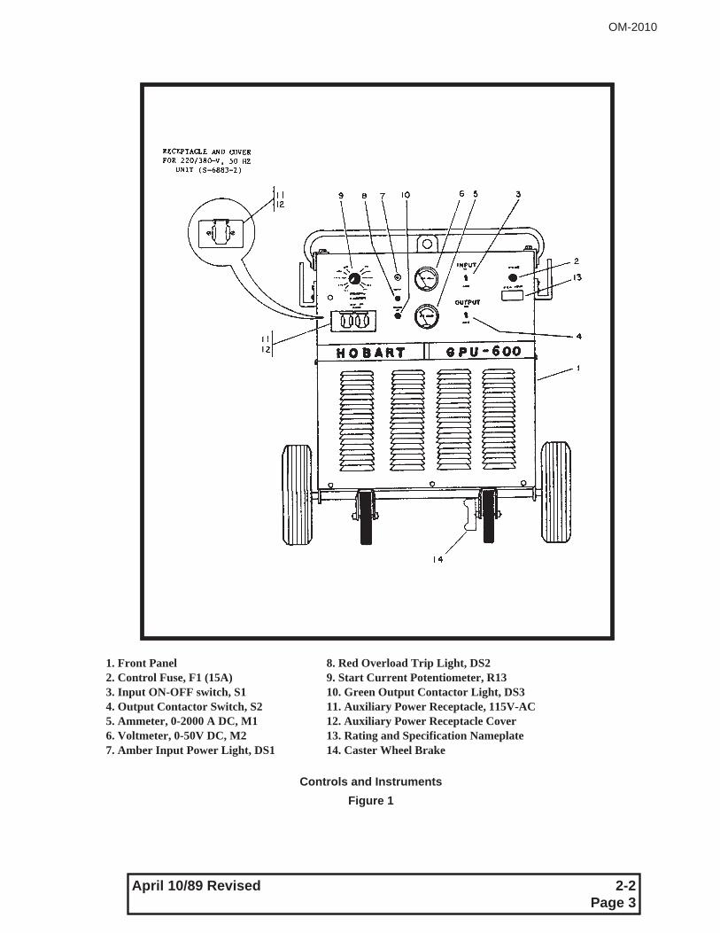
1. Front Panel 8. Red Overload Trip Light, DS22. Control Fuse, F1 (15A) 9. Start Current Potentiometer, R133. Input ON-OFF switch, S1 10. Green Output Contactor Light, DS34. Output Contactor Switch, S2 11. Auxiliary Power Receptacle, 115V-AC5. Ammeter, 0-2000 A DC, M1 12. Auxiliary Power Receptacle Cover6. Voltmeter, 0-50V DC, M2 13. Rating and Specification Nameplate7. Amber Input Power Light, DS1 14. Caster Wheel Brake
Controls and Instruments
Figure 1
OM-2010
April 10/89 Revised 2-2Page 3

This page intentionally left blank.
OM-2010
2-2 April 10/89 RevisedPage 4
CHAPTER 3. SERVICING
SECTION 1. MAINTENANCE
1. General
To be certain the DC power supply set is ready for operation at all times, it must be inspected and main-tained systematically so that defects may be discovered and corrected before they result in serious dam-age or failure of the equipment. Defects discovered during operation of the unit should be noted forcorrection to be made as soon as operation has ceased.
WARNING: HIGH VOLTAGE - ELECTRIC SHOCK CAN KILL! BE CERTAINTHE INPUT POWER SOURCE IS TURNED OFF BEFORE PROCEEDING WITHANY INSPECTION OR MAINTENANCE OPERATION WHICH COULD BRINGPERSONNEL IN CONTACT WITH HIGH VOLTAGE OR REVOLVING EQUIP-MENT. STOP OPERATION IMMEDIATELY IF A POSSIBLE DANGEROUSFAULT IS DISCOVERED. THE FRONT PANEL INPUT CONTACTOR SWITCHDOES NOT REMOVE INPUT POWER FROM ALL COMPONENTS. BE SURECAPACITORS ARE DISCHARGED BEFORE YOU TOUCH.
The power supply is designed to be as maintenance free as possible, therefore, there are few inspectionand maintenance requirements.
2. Inspection
A periodic inspection schedule should be established and maintained. A suggested inspection/checkschedule is provided in Section 3-2, Figure 1; however, it may be changed as required to meet varying op-erating conditions and environment. See Section 2, Inspection/Check for inspection and check proce-dures to be used in conjunction with Section 3-2, Figure 1 schedule.
3. Lubrication
The subject of lubrication is mentioned here mostly to inform maintenance personnel that it has not beenoverlooked. Except for sleeve bearings in the fan motor, no lubrication is required. Refer to Section 1-2,Para. F for fan motor lubrication instructions.
NOTE: The fan motor is designed for 10,000 hours between bearing lubrications. Relubrication for evenlonger life at 10,000 hours requires fan motor removal and dissassembly, possible but not normallyrecommended.
A good silicone spray lubricant is recommended for hinges if exposure to weather should make them diffi-cult to operate.
OM-2010
April 10/89 Revised 3-1Page 1
4. Parts Replacement
A. Minor electrical components
(1) Lamps and fuses are mortality type items which require simple periodic replacement.
(2) Switches, meters, contactors and fan motor in the power supply fall into the category of partswhich can be expected to fail at infrequent, irregular intervals. Instructions for repair and replace-ment of these parts are obvious. Be certain the input power is turned off. Obtain the replacementpart specified in the parts list. Replace the part by substituting the new part for the old taking carenot to mix up the leads. See Sections 2 and 3.
(3) The user-supplied disconnecting means must be of proper capacity for the rated input voltage.See the rating for your input as listed for your use in 1-2, Figure 1, recommended wire size table.Be certain your specification number is designed for your input voltage. No visible inspection ispossible, except for the marked rating if the input power source is off. The use of the wrong inputvoltage could be the cause for equipment damage.
B. Major Electrical Components
(1) Major electrical components such as the power transformer, filter choke, and SCR devices onthe SCR heat sink assembly should be replaced or repaired at an overhaul type facility.
(2) The firing circuit board can be easily replaced as a “plug-in” assembly. Minor calibration adjust-ment may be required for optimum performance. It is recommended, however, that this adjust-ment be made only by factory authorized personnel.
(3) The flyback rectifier diode located on the main SCR heat sink assembly rarely fails from nor-mal use. If replacement is ever required, be sure to connect the replacement exactly as the origi-nal after torque wrench tightening the nut to the stud at 4.2 to 5.2 foot pounds (5.70 to 7.05newton meters).
(4) SCR device replacement requires extreme care, special tools, and the exact replacement partand technique for optimum performance. The replacement of the SCR should be done at the fac-tory or an authorized repair facility. A replacement SCR bridge subassembly can be obtainedfrom the factory which would allow the customer to install so long as he was certain to exactly re-place all leads and components in the same position with the same hardware. This task wouldstill require considerable care and time.
OM-2010
3-1 April 10/89 RevisedPage 2
Section 2. INSPECTION CHECK AND REPAIR
1. General
This section describes inspections and checks to be performed in conjunction with Inspection/CheckSchedule, Figure 1. For satisfactory service, keep the power supply clean, dry, and well ventilated. At theprescribed intervals or more often as necessary, disconnect the power supply from the input powersource and wipe and blow out all dirt and other foreign materials from the internal components, includingthe fan blades. Air pressure should not exceed 25 ps; (172 kPA).
2. Exterior Cables and Connections
A. Input and Output Cables
Observe general condition of power input cables and equipment output cables. Inspect for cuts andabrasions in the insulation which could cause a short circuit. Visually inspect the output cable plugconnector for physical damage and evidence of overheating.
B. Cable Connections
Check all input and output cable connections for tightness and security.
WARNING: HIGH VOLTAGE - ELECTRIC SHOCK CAN KILL! TURN THESOURCE OF INPUT POWER OFF WHEN CHECKING THESE CONNECTIONS.BE CERTAIN CAPACITORS ARE DISCHARGED BEFORE TOUCHING THECIRCUITRY.
3. Controls and Instruments
A. Voltmeter, Ammeter and Control Switches
These components can be damaged by abuse, shipping, and type of use. Observe these instrumentsat each “start-up” to verify they are operating. If one of the meters is suspected of being inaccurate,check it against a master, or test instrument. Replace any faulty or intermittently faulty switches imme-diately.
B. Indicating Lights
(1) Power input and output lights
Life of incandescent bulbs varies with the magnitude of voltage and vibration. Check the lamps(bulbs) in these lights by substituting a known good replacement lamp. If the lights do not glow af-ter the replacement, the circuitry is defective and should be repaired. If the proper voltagereaches the base terminals, replace the base; if not correct the wiring fault.
OM-2010
April 10/89 Revised 3-2Page 1
(2) Overload trip indicating light
More than 31.5 V DC output or overcurrent trips overload trip light DS2. The light emitting diodecircuit resets when S1 power on switch is cycled off and back on after the cause of the trip hasbeen removed. The LED light does not fail in normal use. Applying reverse voltage or overvoltageto it during a test would be a more probable cause for failure, therefore applying a direct test isnot recommended. A bad light does not come on during a trip.
C. Overload Thermostat
The S5 overload thermostat must be closed in order for the DS2 overload light not to be on duringequipment turn-on. If AC power input is disconnected, verify continuity exists between the two S5terminals with the leads to one of the terminals disconnected. Replace the S5 thermostat if thewiring terminals on the S5 thermostat are not shorted.
D. Starting Current Limit Potentiometer
If the R13 starting current control has no effect on the output current above 250 A DC, check theintegrity of the R13 potentiometer before replacing the solid state control board. With input poweroff and the R13 potentiometer slider terminal disconnected from the wiring, the resistance to theslider terminal from each end of the potentiometer should change smoothly as the knob is turned.If not, replace the potentiometer and retest. If retesting shows no change, the printed circuit con-trol board is probably faulty also.
OM-2010
3-2 April 10/89 RevisedPage 2
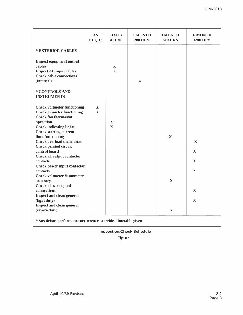
AS DAILY 1 MONTH 3 MONTH 6 MONTHREQ'D 8 HRS. 200 HRS. 600 HRS. 1200 HRS.
* EXTERIOR CABLES
Inspect equipment outputcables XInspect AC input cables XCheck cable connections(internal) X
* CONTROLS ANDINSTRUMENTS
Check voltmeter functioning XCheck ammeter functioning XCheck fan thermostatoperation XCheck indicating lights XCheck starting currentlimit functioning XCheck overload thermostat XCheck printed circuitcontrol board XCheck all output contactorcontacts XCheck power input contactorcontacts XCheck voltmeter & ammeteraccuracy XCheck all wiring andconnections XInspect and clean general(light duty) XInspect and clean general(severe duty) X
* Suspicious performance occurrence overrides timetable given.
Inspection/Check Schedule
Figure 1
OM-2010
April 10/89 Revised 3-2Page 3
E. Contactors
(1) Output Contactor, K2
The output contactor has contacts that can be visually inspected whenever the input power is re-moved from the power supply. If the contacts are badly burned the contactor should be replacedas soon as possible. Slightly pitted and burned contacts can be cleaned up with a commercialcontact cleaner and very fine grained emery cloth or equivalent. If application of 28 V DC to thecoil of the K2 contactor does not make the normally open contacts close completely or the nor-mally open contacts open completely, the contactor should be replaced if the contact mechanismcan’t be mechanically adjusted for proper operation.
(2) Input Contactor, K1
If input power has been turned off at the source of power, the K1 input contactor contacts can bevisually inspected by removing the two screws holding the contact cover in place. If the contactsare badly eroded, burned, or stuck, the replacement contacts and spring for each pole can be or-dered with the number given in the applicable replacement parts list. If the contactor with DS1light on has failed to pick up before the inspection, and no mechanical obstruction has beenfound, the contactor should be replaced or repaired with the replacement coil and contacts speci-fied in the parts list. Many customers prefer to replace the whole contactor, especially for the con-dition showing bad coil and contacts. If DS1 light is good but does not glow and the F8 fusechecks good, the problem is in the control transformer circuit.
F. Control Transformer
The control transformer is located on the rear of the lifting baffle. The F8 fuse (.5A) is normallymounted on top of the control transformer. The voltage input connection on the control transformermust also be changed whenever the input voltage changes.
Not changing the input connection when going from a lower to higher input voltage will result in aburned out control transformer. The same result occurs if a larger than 1/2 ampere fuse is substitutedfor F8, especially if the input contactor is faulty. The only sure way for checking the control trans-former to verify what the input voltage and output voltages are. If there is no proper output with properinput voltage, replace the control transformer.
4. Major Components Check and Repair
A. Main Power Transformer
No replacement parts are available for the main transformer. The replacment power transformer partnumber for your specification number is given in the replacement parts list in Chapter 4. This part andmost of the major component parts can best be replaced at the factory or a factory authorized repairfacility. However, replacement can be done by the customer if he exercises care to reconnect every-thing to the same points and in the same manner as the original part.
WARNING: HIGH VOLTAGE - ELECTRIC SHOCK CAN KILL! TURN THESOURCE OF INPUT POWER OFF WHEN CHECKING THESE CONNECTIONS.BE CERTAIN CAPACITORS ARE DISCHARGED BEFORE TOUCHING THECIRCUITRY.
OM-2010
3-2 April 10/89 RevisedPage 4
Normally, a visual inspection will not find a transformer problem until the failure is very severe. Thetypical inspection is a voltage measurement test for rated primary input voltage and for 6 rated andbalanced line to neutral AC voltages at the transformer secondary terminals. Refer to the applicablevoltage changeover diagram for the input voltage test points and to the applicable connection dia-gram for the transformer secondary test connection points. The normal transformer line to neutral sec-ondary voltage is approximately 33 V AC with no output amperage. Line to line voltage on thesecondary is 66 V. If the fuses blow or circuit breakers trip immediately in the user-supplied discon-nect switch and no evidence of lead shorting exists at the input contactor, or the primary connectionterminal board, both the main transformer and the SCR control assembly are suspect. Open the inputdisconnect switch external to the power supply, label all the transformer leads going to the six U-shaped SCR heat sinks before disconnecting and insulating the leads. Also disconnect the flyback di-ode “pigtail” lead 105 and L1 filter lead 104. These connection changes enables you to check thetransformer only.
After verifying that input power can be turned on from the power source safely, turn the rated inputpower on. After the S1 input contactor switch is closed carefully measure the output line to neutralvoltages if the primary input is still on. If the input power source voltage trips out when the unit isturned on, the main transformer has probably failed. To verify failure, disconnect the input power atthe power source and then remove the copper links (jumpers) on the main voltage changeover board.If turning the primary input voltage on, after input breakers at the power source have been reset, re-sults in no high input current, the main transformer is bad.
If the problem still exists, the problem is not in the main transformer. Check the main connection termi-nal board for faulty connections and check the control transformer and input contactor. Go to 4.B if noproblem existed with all the SCR devices disconnected.
B. Silicon Controlled Rectifier Assembly and Flyback Diode
(1) Visual
No visual failure capability is possible with the SCR assembly, except for faulty leads or miscon-nections which we assume have been found and corrected. The input power at the power sourceshould be turned off at the start of the SCR check out.
(2) Voltohmmeter
To check with voltohmmeter, set the meter to the RX1 scale and check for a shorted SCR bymeasuring between each of the 6 U-shaped heat sink and the main heat sink. No reading shouldbe possible with either polarity of lead connection. The flyback diode should read 4 to 14 ohms inone direction and a very high reading with the leads from the voltohmmeter reversed. If the fly-back diode is shorted, (a rare occurrence) replace it with the same type of device (see Chapter 4 -Replacement Parts) taking care to torque the nut to the stud with 4.2 to 5.2 foot. pounds (5.7 to7.05 newton meters). If the SCR bridge has one or more SCR devices showing a short circuit orlow ohmmeter reading, it is recommended that the GPU-600 power supply be sent to the factoryor an authorized repair station for repair. A replacement SCR bridge subassembly can be ob-tained from the factory which would allow the customer to replace the faulty SCR bridge assem-bly without special tools and techniques. He must still be careful to exactly replace all themounted subassemblies and the connection leads exactly as they were on the faulty heat sink as-sembly. Special tools, parts, and techniques are required to replace single SCR devices on theheat sink assembly.
If the SCR heat sink and diode assembly checks good with the voltohmmeter, the componentscould still be failing due to voltage breakdown at voltages above that of the voltohmmeter. Go to4. B. (3) Voltage test.
OM-2010
April 10/89 Revised 3-2Page 5
(3) Voltage Test for SCR Assembly
With input power turned off, reconnect one SCR device at a time and apply power until the inputpower is interrupted by a fault condition or all the SCR devices are connected. The last SCR de-vice to be connected before interruption is faulty. If no fault occurred, the SCR’s are all good. Theinput power should be turned off and the flyback diode mounted on the SCR heat sink shouldhave the pigtail lead reconnected to lead 105. If reapplication of power causes a trip-out, replacethe faulty flyback diode. The diode nut must be torqued to 4.2 to 5.2 foot pounds (5.7 to 7.05 new-ton-meters). If no failure occurred, go to 4. C. after turning input power off.
C. Filter Choke and Capacitor Voltage Test
Reconnect L1 Filter Choke lead 104 to the proper point as shown in the connection diagram. Visuallycheck the C15, C16, and C17 capacitors for indication of a faulty connection which could cause theproblem.
WARNING: CAPACITOR CHARGE CAN INJURE! BE SURE CAPACITORSARE DISCHARGED BEFORE TOUCHING OUTPUT CIRCUITRY. STAY CLEAROF CAPACITORS DURING TESTING. THEY CAN BURST.
Reapply input voltage. If trip out occurs, either the C15, C16, or C17 capacitors, or the connecting wir-ing between them, are shorted. Disconnect the input voltage at once, allow the capacitors time to dis-charge, and disconnect the positive and negative wiring from the capacitor assembly. Replace anyshorted or bad capacitors (having case deformation caused by high shorting amperage), or bad con-necting wiring. If the problem is found to be the L1 filter choke breaking down to ground, anothergrounded component must be present on the (+) side for the high current output to cause the trip outto occur. Check for the second grounded component also.
D. Printed Circuit Control Board
The best, most quick way to verify condition of a suspected printed circuit board is to exchange it for aknown good one. This plug-in substitution method using a known good board also allows the equip-ment to go back on line immediately while the faulty board is sent back to the factory for repair or re-placement. Field repair is not recommended.
Before assuming the board is faulty when you have no spare board perform the following checks:
(a) Check for blown fuses F2 thru F7 and replace bad ones for a retest under power. If unit nowworks, the problem may be solved or an intermittently present one. Keep record of which fuseblew for later assistance.
(b) Check for broken or shorted leads on or to plugs J1, J2, and J3 plugged into the printed circuitcontrol board. Use the applicable schematic and connection diagrams for instructions and lead lo-cations.
(c) Check snubber printed circuit boards on the right side of the SCR heatsink assembly forshorted or broken leads and for signs of overheating.
(d) Check the SCR gate leads for breaks or short circuits and correct any problems found beforeretesting.
OM-2010
3-2 April 10/89 RevisedPage 6
(e) If the reason the pc control board is being checked, and no substitute board exists, is insuffi-ciency of output voltage with proper AC secondary voltage at the main transformer, check forproper pc board voltages (See 3-3), if no oscilloscope is available. If the readings are good, theproblem may be one or more open SCR devices. The best test equipment is an oscilloscope butthe use of a crude SCR tester with the input power off can verify open SCR devices but not hardto fire ones. One type of SCR turn-on tester is a battery power circuit tester with a light bulb in se-ries with the battery and two leads. With input power off, the positive lead is connected to the an-ode of the SCR under test and the negative lead is connected to the cathode of the same SCRdevice. The light should stay off until the gate lead of the same SCR has the positive voltage ap-plied to it. If the light turns on and remains on after the gate lead voltage is removed so long asthe anode and cathode leads stay connected, the SCR is probably good. If the SCR stops con-ducting as soon as the gate lead is removed, an anode to cathode open or very hard to drivefaulty SCR is probable. If any SCR devices are found to be faulty, the printed circuit board maynot be faulty unless the voltages in 3.3 of the pc board test aren’t achievable. Then both compo-nents may be faulty.
OM-2010
April 10/89 Revised 3-2Page 7

This page intentionally left blank
OM-2010
3-2 April 10/89 RevisedPage 8
SECTION 3. CALIBRATION AND TEST OF PC CONTROL BOARD
1. General
This section describes the test points, test values, and adjustment locations for testing and adjustingthe printed circuit control board which is the “brains” of the GPU-600 DC power supply. As a minimumthe following equipment and tools are required.
A. High impedance, high accuracy DC voltmeter;
B. Small, standard blade screwdriver;
C. Small, insulated clip leads;
D. A resistance load bank or equivalent that can safely dissipate 2200 ADC at 20-V DC if theovercurrent trip point is to be checked or adjusted.
Faulty control boards should be returned to the manufacturer for repair.
2. Printed Circuit Board Test Values and Adjustments
A. Refer to Figure 1 for the location of test points and adjustment potentiometers for possible fieldadjustment.
B. Test point values and comments about the measurements and testing conditions are tabulatedin Figure 2.
WARNING: ELECTRIC SHOCK AND ARCS CAN KILL OR INJURE! USE ACCESS DOORS TO IN-SPECT, OR TEST THE PRINTED CIRCUIT CONTROL BOARD WHILE THE EQUIPMENT IS RUNNING.THE VOLTAGES ON THE PRINTED CIRCUIT BOARD ARE SAFE; HOWEVER, REMOVING THE RIGHTSIDE PANEL EXPOSES PEOPLE TO DANGEROUS VOLTAGES.
C. Test and Calibration Procedure
Follow Figures 1 and 2 to verify that the PC board is functioning to the standard. If the voltagereadings to the PC board common are not within specification, attempt to correct the reading byadjusting the applicable control. Be certain the operating conditions are exactly as stated in Fig-ure 2. If the board does not adjust and the leads, fuses (F2-F7), and connectors to the PC controlboard are good and proper, the PC control board is faulty. Replace it with a known good board af-ter the input power has been turned off. The PC board is held in place by six (6) self tappingscrews. After unplugging the three polarized connection plugs, remove the screws and keep forthe new board. Reverse the procedure when the new PC board is mounted in the exact orienta-tion of the old board. Recheck the voltages. In some cases a minor adjustment may be requiredfor optimum calibration. If the same magnitude of error and lack of adjustment control is encoun-tered, it is possible that the control board is not at fault.
Consideration should be given to returning the GPU-600 DC power supply to the factory or anauthorized repair facility if your recheck of the GPU-600 does not find the cause of the difficulty.Field repair of the PC control board is not recommended.
OM-2010
April 10/89 Revised 3-3Page 1

CAUTION: IMPROPER TEST EQUIPMENT CAN DAMAGE! USE ONLY RECOMMENDED TESTEQUIPMENT AND TOOLS. NEVER APPLY TEST VOLTAGE DIRECTLY TO COMPONENTS ONTHE BOARD. THIS SOLID STATE CONTROL USES LOW CURRENT DEVICES THAT QUICKLYBURN OUT IF A LOW IMPEDANCE VOLTAGE SOURCE IS APPLIED DIRECTLY TO THE COM-PONENT. THE DEVICE MAY NOT FAIL UNTIL LATER FROM THE TEST.
OM-2010
3-3 April 10/89 RevisedPage 2
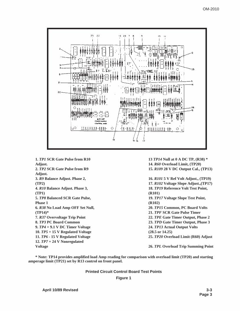
1. TP1SCR Gate Pulse from R10 13TP14Null at 0 A DC TP, (R38) *Adjust. 14. R60Overload Limit, (TP20)2. TP2SCR Gate Pulse from R9 15.R10928 V DC Output Cal., (TP13)Adjust.3. R9 Balance Adjust. Phase 2, 16.R1015 V Ref Volt Adjust., (TP19)(TP2) 17.R102Voltage Slope Adjust.,(TP17)4. R10Balance Adjust. Phase 3, 18.TP19Reference Volt Test Point,(TP1) (R101)5. TP8Balanced SCR Gate Pulse, 19.TP17Voltage Slope Test Point,Phase 1 (R102)6. R38No Load Amp OFF Set Null, 20.TP15Common, PC Board Volts(TP14)* 21.TPF SCR Gate Pulse Timer7. R37Overvoltage Trip Point 22.TPE Gate Timer Output, Phase 28. TP3PC Board Common 23.TPD Gate Timer Output, Phase 39. TP4+ 9.1 V DC Timer Voltage 24.TP13Actual Output Volts10.TP5+ 15 V Regulated Voltage (28.5 or 14.25)11.TP6 - 15 V Regulated Voltage 25.TP20Overload Limit (R60) Adjust12.TP7+ 24 V NonregulatedVoltage 26.TPL Overload Trip Summing Point
* Note: TP14 provides amplified load Amp reading for comparison with overload limit (TP20) and startingamperage limit (TP21) set by R13 control on front panel.
Printed Circuit Control Board Test Points
Figure 1
OM-2010
April 10/89 Revised 3-3Page 3
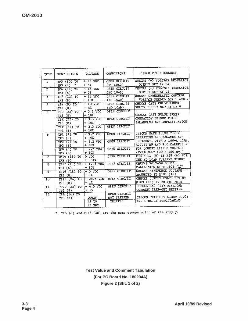
Test Value and Comment Tabulation
(For PC Board No. 180294A)
Figure 2 (Sht. 1 of 2)
OM-2010
3-3 April 10/89 RevisedPage 4
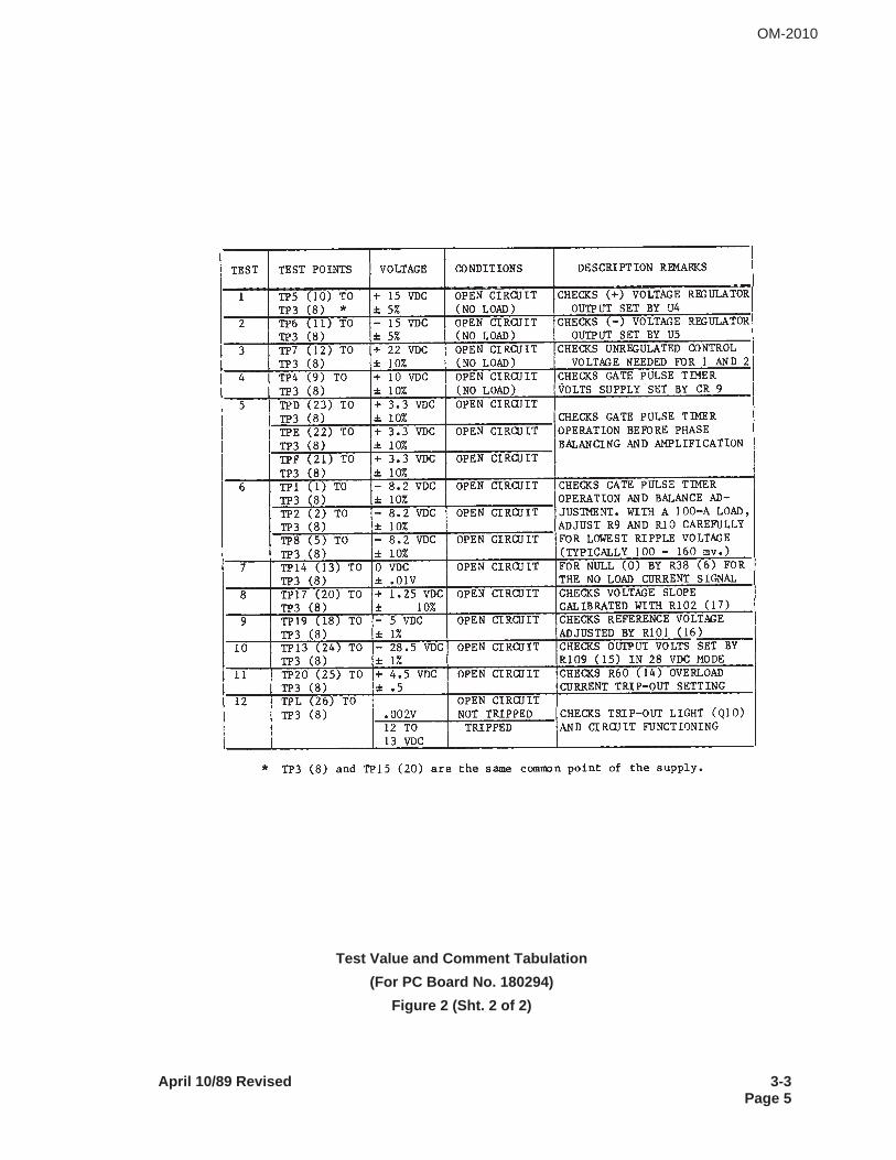
Test Value and Comment Tabulation
(For PC Board No. 180294)
Figure 2 (Sht. 2 of 2)
OM-2010
April 10/89 Revised 3-3Page 5

This page intentionally left blank
OM-2010
3-3 April 10/89 RevisedPage 6
SECTION 4. TROUBLESHOOTING
1. General
A. Troubleshooting is an orderly process of checking and eliminating possible causes of trouble until theexact cause of a trouble is found. As a rule, the best place to start looking for the cause of a trouble in acircuit is at the source of power. Continue testing and checking the circuit, step-by-step, in an orderly man-ner, until the cause of trouble is located. See applicable connection diagrams and schematic diagrams.Do not overlook the obvious. Loose connections are the primary cause of malfunctions, both internal andexternal to the machine. Do not overlook bad grounds, wrong settings, or worn out contactors.
Test points are identified on schematic diagrams listed in Chapter 5. P.C. Board test points are identifiedand test point values are given in Section 3-3, Figures 1 and 2. The minimum equipment needed to trou-bleshoot this machine is a simple voltohmmeter. An oscilloscope is the best device to find and correct diffi-cult problems.
B. This section provides information useful in diagnosing and correcting certain troubles which cause un-satisfactory operation or failure of the equipment.
C. Minor troubles may be remedied by the operator; however, major repairs must be undertaken by expe-rienced mechanics and electricians only. Replacement of SCR devices are to be performed at the factoryor an authorized service center.
2. Troubleshooting (See Figure 1)
A. Description The troubleshooting chart lists information under three headings:
(1) Trouble, symptom, and condition
(2) Probable cause
(3) Test, check, and remedy
B. Use of the Troubleshooting Chart
The troubleshooting chart is designed to provide maintenance and repair personnel with a time-savingguide for locating the source of a trouble.
(1) Terminal points (Ref. applicable schematic and connection diagrams), installed on the power sup-ply at several locations, provide easily accessible and identifiable test points for checking circuits andelectrical components.
(2) Test points are located throughout the circuitry in such a manner that input and output power maybe used for test purposes. Because of these test points and their location, a complete check of cir-cuitry may be completed very quickly. Therefore, “probable causes” and “remedies” are listed in astep-by-step sequence which will insure power for testing in all instances where input or output powermay be used with proper safety practices, test equipment, and training experience.
(3) Printed circuit board output troubles should be pinpointed only to determine if the problem is aboard calibration problem or a PC board failure problem. Failure of PC board requires replacement ofthe board. Field repair attempts are not recommended. See 3-3 for calibration instructions.
OM-2010
April 10/89 Revised 3-4Page 1
(4) Always check circuit fuses, circuit breakers and the position of switches first in troubleshooting.The incorrect positioning of a switch may cause a condition which could be misinterpreted as a fault.
(5) Electrical component symbols, which are used on schematic diagrams, and their legends to iden-tify components, may be used in the troubleshooting chart (in parentheses after the item name) tohelp maintenance personnel identify parts on the schematic diagrams.
3. Equipment for Troubleshooting
A good quality multi-scale voltohmmeter is the only instrument required for troubleshooting. However, forchecking certain erratic, intermittent, or phase relationship problems, a good oscilloscope is strongly rec-ommended.
4. Safety
WARNING: HIGH VOLTAGE - ELECTRIC SHOCK AND FIRE CAN KILL! EXER-CISE EXTREME CARE TO AVOID CONTACT WITH HIGH VOLTAGE LEADSAND COMPONENTS WHICH COULD CAUSE SERIOUS SHOCK AND INJURYIF TOUCHED WHEN TROUBLESHOOTING OR OPERATING THE EQUIPMENT.STAY CLEAR OF MOVING PARTS. LOCATE EQUIPMENT IN A SAFE ENVI-RONMENT. HAVE PROPER SAFETY EQUIPMENT AVAILABLE. DO NOT AT-TEMPT OPERATION OR REPAIR WITHOUT ADEQUATE TRAINING.
5. Voltages of Interest
A. Across the secondary on all 3 phases - 66 VAC + 10% *
B. To secondary coil center tap on all phases - 33 VAC + 10% *
* The + 10% refers to the possibility of input voltage being out of balance or not at the nominalvalue.
C. Across the 115 VAC receptacle - 115 VAC + 10% *
D. Between X1 and X3 on Fuse Block - 37 VAC + 10% *
E. Test Point Values for PC board
A control board malfunction will probably result in (a) a loss of output voltage, (b) inability to producefull load current, or (c) output voltage too high or too low. See Section 3-3, Figure 2 for nominal testvalues between a few selected test points shown in Section 3-3, Figure 1.
NOTE: All potentiometer operating values are preset at the factory, and normally should not have to bereset in the field. If a need arises that would indicate the need for field adjustments, please contact thefactory at Troy, Ohio. Typically, R109, (28 V output) is the only factory set value which the customer’suse might dictate a minor change in setting. For example, long cables might need a few tenths of a volthigher set values to compensate for the cable drop.
OM-2010
3-4 April 10/89 RevisedPage 2
6. SCR Malfunction Instructions
A. Normal SCR Malfunction Conditions
(1) Blown line fuses as the result of a shorted SCR (similar to a shorted diode). A shorted flyback di-ode will also produce this situation. This is a severe malfunction. See 6B.
(2) If one SCR does not turn on [(either it is open or the gate signal is not being received by the SCR(gate circuit open)], a very small change will occur at the output which will be difficult to notice. Theripple voltage at the output will increase.
(3) If two SCRs do not turn on, the ripple current will increase and can cause other problems. (Con-sult troubleshooting procedure)
B. Severe SCR Malfunction Conditions
(1) In the case of a severe malfunction, such as a shorted SCR or diode, do not turn on the unit. Dis-connect the leads from the transformer to the heat sink assembly and check with a VOM for shortedSCRs or a shorted flyback diode.
(2) To eliminate the possibility of a control malfunction, go inside the unit and check the control circuitboard. See the instructions provided for this test. It is important to run through the tests in the orderthey are listed. Note that the SCR devices and flyback diode are still disconnected.
C. SCR tests or checks
(1) If nothing is found defective on the board the next step is to go to the SCRs. First of all an opengate or an open SCR cannot be checked with a VOM. If an SCR is not firing, the AC ripple current willincrease across the filter capacitors, but no fuses blow. Also, the ripple voltage will increase at the out-put.
(2) The best way of checking for a SCR device or flyback diode which breaks down into a shorted con-dition because of inadequate voltage withstand capability is to add one component at a time and thenturn on the input power for a short time. When the faulty component gets connected, excessive inputcurrent will flow.
WARNING: ELECTRIC SHOCK AND FIRE CAN KILL! DO NOT TOUCH ENER-GIZED PARTS. DO NOT LEAVE POWER SUPPLY ON LONG ENOUGH TOOVERHEAT OR FAIL IN THE FAULTY CONDITION.
(3) The best way to check that all SCR devices are firing and conducting correctly is to connect theprobe of an oscilloscope to the heat sink and the isolated neutral of the oscilloscope to the braid ofthe flyback diode. The SCR pulses will show as 6 evenly spaced pulses of about the same height. Ifone of the pulses appears to be part of a malfunction SCR device circuit, the gate lead for that devicemay be disconnected from the applicable suppressor board point. The lead disconnection which doesnot affect the trace is the lead for the SCR device and suppressor circuit in question. However, ifevery third pulse is low or missing, check the balance adjustments, R9 and R10, before attributing theproblem to faulty components.
OM-2010
April 10/89 Revised 3-4Page 3
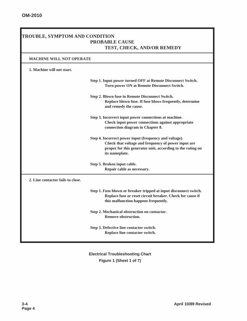
TROUBLE, SYMPTOM AND CONDITIONPROBABLE CAUSE
TEST, CHECK, AND/OR REMEDY
MACHINE WILL NOT OPERATE
1. Machine will not start.
Step 1. Input power turned OFF at Remote Disconnect Switch.Turn power ON at Remote Disconnect Switch.
Step 2. Blown fuse in Remote Disconnect Switch.Replace blown fuse. If fuse blows frequently, determineand remedy the cause.
Step 3. Incorrect input power connections at machine.Check input power connections against appropriateconnection diagram in Chapter 8.
Step 4. Incorrect power input (frequency and voltage).Check that voltage and frequency of power input areproper for this generator unit, according to the rating onits nameplate.
Step 5. Broken input cable.Repair cable as necessary.
2. Line contactor fails to close.
Step 1. Fuse blown or breaker tripped at input disconnect switch.Replace fuse or reset circuit breaker. Check for cause ifthis malfunction happens frequently.
Step 2. Mechanical obstruction on contactor.Remove obstruction.
Step 3. Defective line contactor switch.Replace line contactor switch.
Electrical Troubleshooting Chart
Figure 1 (Sheet 1 of 7)
OM-2010
3-4 April 10/89 RevisedPage 4
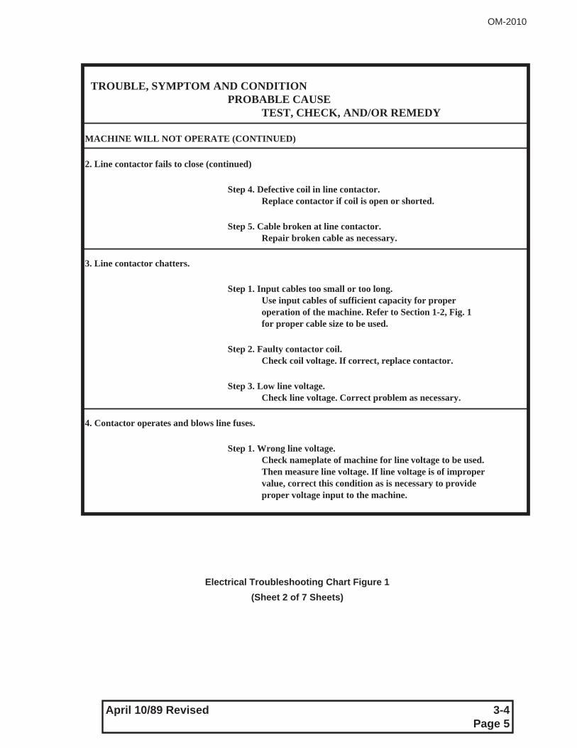
TROUBLE, SYMPTOM AND CONDITIONPROBABLE CAUSE
TEST, CHECK, AND/OR REMEDY
MACHINE WILL NOT OPERATE (CONTINUED)
2. Line contactor fails to close (continued)
Step 4. Defective coil in line contactor.Replace contactor if coil is open or shorted.
Step 5. Cable broken at line contactor.Repair broken cable as necessary.
3. Line contactor chatters.
Step 1. Input cables too small or too long.Use input cables of sufficient capacity for properoperation of the machine. Refer to Section 1-2, Fig. 1for proper cable size to be used.
Step 2. Faulty contactor coil.Check coil voltage. If correct, replace contactor.
Step 3. Low line voltage.Check line voltage. Correct problem as necessary.
4. Contactor operates and blows line fuses.
Step 1. Wrong line voltage.Check nameplate of machine for line voltage to be used.Then measure line voltage. If line voltage is of impropervalue, correct this condition as is necessary to provideproper voltage input to the machine.
Electrical Troubleshooting Chart Figure 1
(Sheet 2 of 7 Sheets)
OM-2010
April 10/89 Revised 3-4Page 5
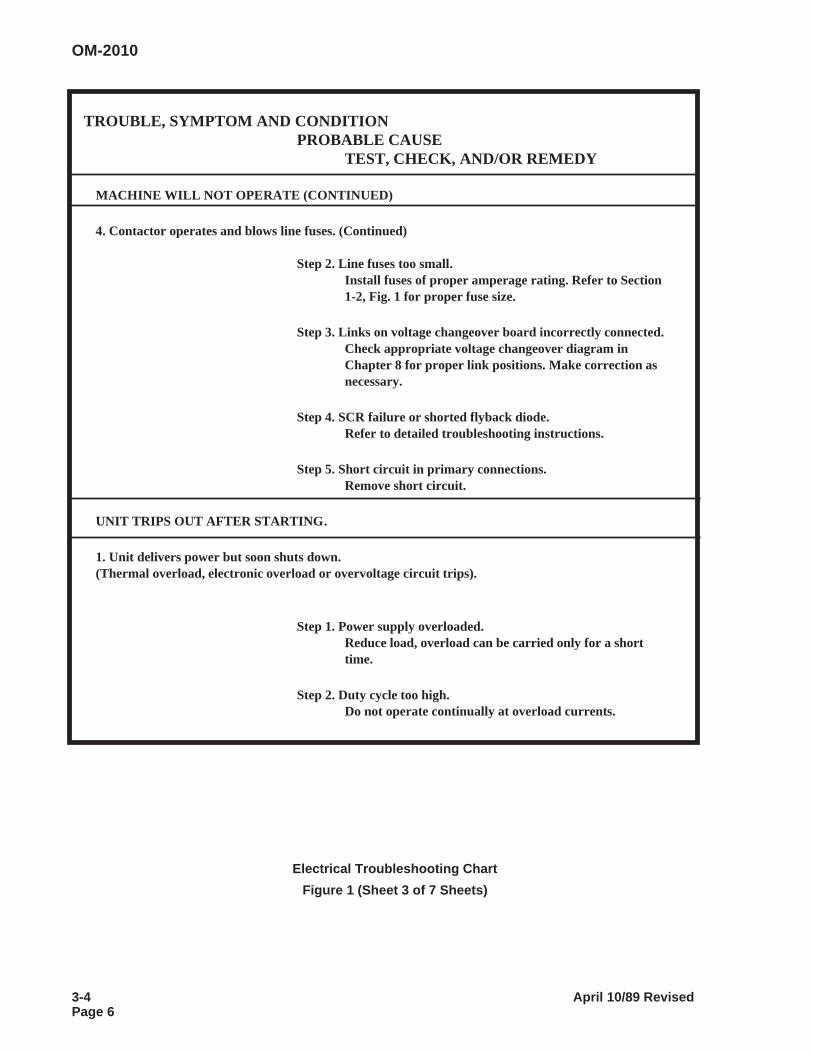
TROUBLE, SYMPTOM AND CONDITIONPROBABLE CAUSE
TEST, CHECK, AND/OR REMEDY
MACHINE WILL NOT OPERATE (CONTINUED)
4. Contactor operates and blows line fuses. (Continued)
Step 2. Line fuses too small.Install fuses of proper amperage rating. Refer to Section1-2, Fig. 1 for proper fuse size.
Step 3. Links on voltage changeover board incorrectly connected.Check appropriate voltage changeover diagram inChapter 8 for proper link positions. Make correction asnecessary.
Step 4. SCR failure or shorted flyback diode.Refer to detailed troubleshooting instructions.
Step 5. Short circuit in primary connections.Remove short circuit.
UNIT TRIPS OUT AFTER STARTING.
1. Unit delivers power but soon shuts down.(Thermal overload, electronic overload or overvoltage circuit trips).
Step 1. Power supply overloaded.Reduce load, overload can be carried only for a shorttime.
Step 2. Duty cycle too high.Do not operate continually at overload currents.
Electrical Troubleshooting Chart
Figure 1 (Sheet 3 of 7 Sheets)
OM-2010
3-4 April 10/89 RevisedPage 6
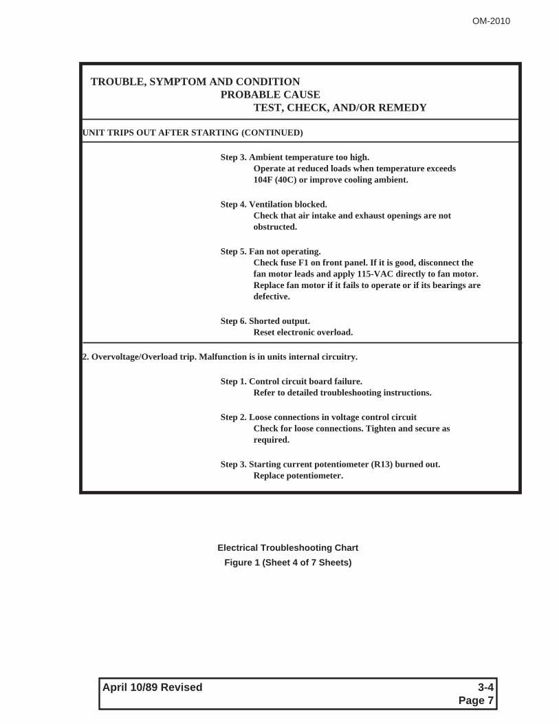
TROUBLE, SYMPTOM AND CONDITIONPROBABLE CAUSE
TEST, CHECK, AND/OR REMEDY
UNIT TRIPS OUT AFTER STARTING (CONTINUED)
Step 3. Ambient temperature too high.Operate at reduced loads when temperature exceeds104F (40C) or improve cooling ambient.
Step 4. Ventilation blocked.Check that air intake and exhaust openings are notobstructed.
Step 5. Fan not operating.Check fuse F1 on front panel. If it is good, disconnect thefan motor leads and apply 115-VAC directly to fan motor.Replace fan motor if it fails to operate or if its bearings aredefective.
Step 6. Shorted output.Reset electronic overload.
2. Overvoltage/Overload trip. Malfunction is in units internal circuitry.
Step 1. Control circuit board failure.Refer to detailed troubleshooting instructions.
Step 2. Loose connections in voltage control circuitCheck for loose connections. Tighten and secure asrequired.
Step 3. Starting current potentiometer (R13) burned out.Replace potentiometer.
Electrical Troubleshooting Chart
Figure 1 (Sheet 4 of 7 Sheets)
OM-2010
April 10/89 Revised 3-4Page 7
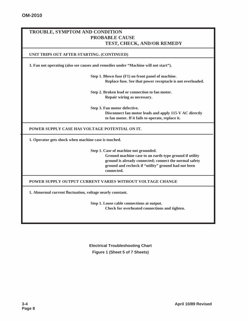
TROUBLE, SYMPTOM AND CONDITIONPROBABLE CAUSE
TEST, CHECK, AND/OR REMEDY
UNIT TRIPS OUT AFTER STARTING. (CONTINUED)
3. Fan not operating (also see causes and remedies under “Machine will not start”).
Step 1. Blown fuse (F1) on front panel of machine.Replace fuse. See that power receptacle is not overloaded.
Step 2. Broken lead or connection to fan motor.Repair wiring as necessary.
Step 3. Fan motor defective.Disconnect fan motor leads and apply 115-V AC directlyto fan motor. If it fails to operate, replace it.
POWER SUPPLY CASE HAS VOLTAGE POTENTIAL ON IT.
1. Operator gets shock when machine case is touched.
Step 1. Case of machine not grounded.Ground machine case to an earth-type ground if utilityground is already connected; connect the normal safetyground and recheck if “utility” ground had not beenconnected.
POWER SUPPLY OUTPUT CURRENT VARIES WITHOUT VOLTAGE CHANGE
1. Abnormal current fluctuation, voltage nearly constant.
Step 1. Loose cable connections at output.Check for overheated connections and tighten.
Electrical Troubleshooting Chart
Figure 1 (Sheet 5 of 7 Sheets)
OM-2010
3-4 April 10/89 RevisedPage 8
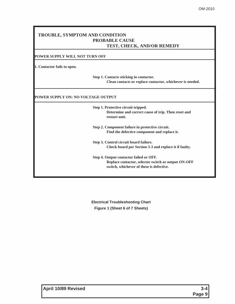
TROUBLE, SYMPTOM AND CONDITIONPROBABLE CAUSE
TEST, CHECK, AND/OR REMEDY
POWER SUPPLY WILL NOT TURN OFF
1. Contactor fails to open.
Step 1. Contacts sticking in contactor.Clean contacts or replace contactor, whichever is needed.
POWER SUPPLY ON: NO VOLTAGE OUTPUT
Step 1. Protective circuit tripped.Determine and correct cause of trip. Then reset andrestart unit.
Step 2. Component failure in protective circuit.Find the defective component and replace it.
Step 3. Control circuit board failure.Check board per Section 3-3 and replace it if faulty.
Step 4. Output contactor failed or OFF.Replace contactor, selector switch or output ON-OFFswitch, whichever of these is defective.
Electrical Troubleshooting Chart
Figure 1 (Sheet 6 of 7 Sheets)
OM-2010
April 10/89 Revised 3-4Page 9
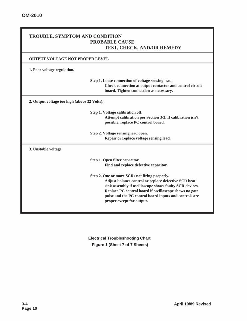
TROUBLE, SYMPTOM AND CONDITIONPROBABLE CAUSE
TEST, CHECK, AND/OR REMEDY
OUTPUT VOLTAGE NOT PROPER LEVEL
1. Poor voltage regulation.
Step 1. Loose connection of voltage sensing lead.Check connection at output contactor and control circuitboard. Tighten connection as necessary.
2. Output voltage too high (above 32 Volts).
Step 1. Voltage calibration off.Attempt calibration per Section 3-3. If calibration isn’tpossible, replace PC control board.
Step 2. Voltage sensing lead open.Repair or replace voltage sensing lead.
3. Unstable voltage.
Step 1. Open filter capacitor.Find and replace defective capacitor.
Step 2. One or more SCRs not firing properly.Adjust balance control or replace defective SCR heatsink assembly if oscilloscope shows faulty SCR devices.Replace PC control board if oscilloscope shows no gatepulse and the PC control board inputs and controls areproper except for output.
Electrical Troubleshooting Chart
Figure 1 (Sheet 7 of 7 Sheets)
OM-2010
3-4 April 10/89 RevisedPage 10
CHAPTER 4. ILLUSTRATED PARTS LIST
SECTION 1. INTRODUCTION
1. General
The Illustrated Parts List identifies, describes, and illustrates main assemblies, subassemblies, and detailparts of the GPU-600 Series, SCR Phase controlled, DC power supply manufactured by Ground PowerGroup, Hobart Brothers Company, Troy, Ohio, and identified as Specification No. S6683 or 6883A with ap-plicable dash number. Any options will have its own descriptive literature when required.
2. Purpose
The purpose of this list is to provide parts identification and descriptive information to maintenance andprovisioning personnel for use in provisioning, requisitioning, purchasing, storing, and issuing of spareparts.
3. Arrangement
Chapter 4 is arranged as follows:
Table of Contents
Section 1 - Introduction
Section 2 - Manufacturer’s Codes
Section 3 - Parts List
Section 4 - Numerical Index
4. Explanation of Parts List
A. Contents
The parts list contains a breakdown of the equipment into assemblies, subassemblies, and detailparts. All parts of the equipment are listed except:
(1) Standard hardware items (attaching parts) such as nuts, screws, washers, etc., which areavailable commercially.
(2) Bulk items such as wire, cable, sleeving, tubing, etc., which are also commercially available.
(3) Permanently attached parts which lose their identity by being welded, soldered, riveted, etc.,to other parts, weldments, or assemblies.
OM-2010
April 10/89 Revised 4-1Page 1
B. Parts List Form
This form is divided into five columns. Beginning at the left side of the form and proceeding to theright, columns are identified as follows:
(1) “FIGURE-ITEM NO.” Column
This column lists the figure number of the illustration applicable to a particular parts list and alsoidentifies each part in the list by an item number. These item numbers also appear on the illustra-tion. Each item number on an illustration is connected to the part to which it pertains by a leaderline. Thus the figure and item numbering system ties the parts lists to the illustrations and viceversa. The figure and index numbers are also used in the numerical index to assist the user infinding the illustration of a part when the part number is known
(2) “HOBART PART NUMBER” Column
ALL part numbers appearing in this column are Hobart numbers. In all instances where the part isa purchased item, the vendor’s identifying fivedigit code and his part number will appear in the“NOMENCLATURE” column.
Vendor parts which are modified by Hobart will be identified as such in the “NOMENCLATURE”column. In case Hobart does not have an identifying part number for a purchased part, the “HO-BART PART NUMBER” column will reflect “No Number” and the vendor’s number will be shownin the “NOMENCLATURE” column. Parts manufactured by Hobart reflect no vendor code or partnumber in the “NOMENCLATURE” column.
(3) “NOMENCLATURE” Column
The item identifying name appears in this column. The indenture method is used to indicate itemrelationship. Thus, components of an assembly are listed directly below the assembly and in-dented one space. Vendor codes and part numbers for purchased parts are shown in this col-umn. Hobart modification to vendor items is also noted in this column.
(4) “EFF” (Effective) Column
This column is used to indicate the applicability of parts to different models of equipment. Whenmore than one model of equipment is covered by a parts list, there are some parts which areused on only one model. This column is used for insertion of a code letter “A”, “B”, etc., to indicatethese parts and to identify the particular model they are used on.
Parts in this manual are coded as follows:
Parts coded “A” are usable on Specs 6883-1 only.
Parts coded “B” are usable on Specs 6883-2 only.
Parts coded “C” are usable on Specs 6883A-1 only.
Parts coded “D” are usable on Specs 6883A-2 only.
Parts coded “E” are usable on Specs 6883A-3 only.
(5) “UNITS PER ASSEMBLY” Column
This column indicates the quantity of parts required for an assembly or subassembly in which thepart appears. This column does not necessarily reflect the total used in the complete end item.
OM-2010
4-1 April 10/89 RevisedPage 2
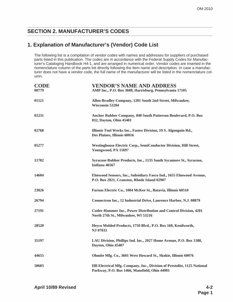
SECTION 2. MANUFACTURER’S CODES
1. Explanation of Manufacturer’s (Vendor) Code List
The following list is a compilation of vendor codes with names and addresses for suppliers of purchasedparts listed in this publication. The codes are in accordance with the Federal Supply Codes for Manufac-turer’s Cataloging Handbook H4-1, and are arranged in numerical order. Vendor codes are inserted in thenomenclature column of the parts list directly following the item name and description. In case a manufac-turer does not have a vendor code, the full name of the manufacturer will be listed in the nomenclature col-umn.
CODE VENDOR’S NAME AND ADDRESS00779 AMP Inc., P.O. Box 3608, Harrisburg, Pennsylvania 17105
01121 Allen-Bradley Company, 1201 South 2nd Street, Milwaukee,Wisconsin 53204
02231 Anchor Rubber Company, 840 South Patterson Boulevard, P.O. Box832, Dayton, Ohio 45401
02768 Illinois Tool Works Inc., Fastex Division, 19 S. Algonguin Rd.,Des Plaines, Illinois 60016
05277 Westinghouse Electric Corp., SemiConductor Division, Hill Street,Youngwood, PA 15697
11702 Syracuse Rubber Products, Inc., 1135 South Sycamore St., Syracuse,Indiana 46567
14604 Elmwood Sensors, Inc., Subsidiary Fasco Ind., 1655 Elmwood Avenue,P.O. Box 2821, Cranston, Rhode Island 02907
23826 Furnas Electric Co., 1004 McKee St., Batavia, Illinois 60510
26794 Connectron Inc., 12 Industrial Drive, Laurence Harbor, N.J. 08879
27191 Cutler-Hammer Inc., Power Distribution and Control Division, 4201North 27th St., Milwaukee, WI 53216
28520 Heyco Molded Products, 1750 Blvd., P.O. Box 160, Kenilworth,NJ 07033
35197 LAU Division, Phillips Ind. Inc., 2027 Home Avenue, P.O. Box 1388,Dayton, Ohio 45407
44655 Ohmite Mfg. Co., 3601 West Howard St., Skokie, Illinois 60076
50603 HB Electrical Mfg. Company, Inc., Division of Prestolite, 1125 NationalParkway, P.O. Box 1466, Mansfield, Ohio 44901
OM-2010
April 10/89 Revised 4-2Page 1
CODE VENDOR’S NAME AND ADDRESS51285 Woodrow Mfg. Company, 4300 River Rd., P.O. Box 1567, Springfield,
Ohio 4550156289 Sprague Electric Company, 87 Marshall St., North Adams, Mass.
0124760741 Triplett Electrical Instrument Company, Harmon Road, Bluffton,
Ohio 4581762119 Universal Electric Company, 300 E. Main St., Owosso, Michigan 48867
70485 Atlantic India Rubber Works Inc., 571 West Polk St., Chicago,Illinois 60607
71400 Bussman Manufacturing, Division of McGraw-Edison Company, 114Old State Road, P.O. Box 14460, St. Louis, Missouri 63178
71774 General Instrument Corp., Lamp Division, 4433 N. Ravenswood Ave.,Chicago, Illinois 60640
72619 Amperex Electronic Corporation, Dialight Div., 203 Harrison Place,Brooklyn, New York 11237
74545 Hubbell Harvey Inc., 584 Derby Milford Rd., Orange, CT 06477
74559 Carlingswitch Inc., 505 New Park Avenue, West Hartford, CT 06110
77166 Pass and Seymour, P.O. Box 4822, Syracuse, NY 13221
81483 International Rectifier, 9220 Sunset Blvd., Los Angeles, CA 90069
81703 Mulberry Metal Products Inc., 2199 Stanley Terrace, Union, NJ 07083
90201 Emhart Ind. Inc., Mallory Capacitor Co., 4760 Kentucky Ave., P.O. Box372, Indianapolis, Indiana 46206
91929 Honeywell Inc., Microswitch Division, 11 W. Spring St., Freeport,Illinois 61032
97520 Basler Electric Company, Rt. 143, P.O. Box 269, Highland,Illinois 62249
No Number Material Handling Association, 1199 West Goodale Blvd., Columbus,Ohio 43212
No Number Pioneer, Dayton Electronics Div., 4433 Interpoint Drive, Dayton,Ohio 45424
HB Part No. 83B-1100-183B-1100-283B-1101
OM-2010
4-2 April 10/89 RevisedPage 2

SECTION 3. PARTS LIST
1. Explanation of Parts List Arrangement
The parts list is arranged so that the illustration will appear on a left-hand page and the applicable partslist will appear on the opposite right-hand page. Unless the list is unusually long, the user will be able tolook at the illustartion and read the parts list without turning a page.
2. Symbols and abbreviations
The folllowing is a list of symbols and abbreviations used in the parts list.
* - item not illustartedA, or AMP - ampereAC - alternating currentAR - as requiredDC - direct currentFig. - figurehd. - headhex - hexagonHz - Hertz (cycles-per-second)I.D. - inside diameterIN - inchkVA - kilovolt-ampereuF - microfaradNo. - numberOM - Owners ManualPRV - peak reversePSI - pounds per square inchRef - reference ( the item has been listed previously)TM - Technical Manualv - volt (when used as a prefix to a five-digit number, indicates vendor code)
NOTE: An item which does not reflect an index number is an assembly which is not illustrated in itsassembled state, or it is similar (right-hand, left-hand, top, etc.) to an item which is illustarted.
OM-2010
December 16/91 Revised 4-3Page 1
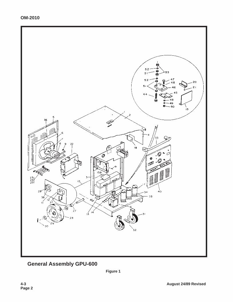
General Assembly GPU-600Figure 1
OM-2010
4-3 August 24/89 RevisedPage 2
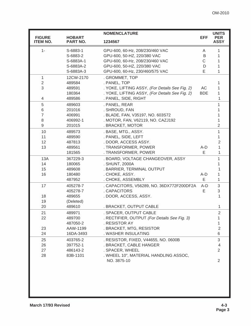
NOMENCLATURE UNITSFIGURE HOBART EFF PER
ITEM NO. PART NO. 1234567 ASSY
1- S-6883-1 GPU-600, 60-Hz, 208/230/460 VAC A 1S-6883-2 GPU-600, 50-HZ, 220/380 VAC B 1S-6883A-1 GPU-600, 60-Hz, 208/230/460 VAC C 1S-6883A-2 GPU-600, 50-HZ, 220/380 VAC D 1S-6883A-3 GPU-600, 60-Hz, 230/460/575 VAC E 1
1 12CW-2170 . GROMMET, TOP2 489584 . PANEL, TOP 13 489591 . YOKE, LIFTING ASSY, (For Details See Fig. 2) AC 1
180364 . YOKE, LIFTING ASSY, (For Details See Fig. 2) BDE 14 489586 . PANEL, SIDE, RIGHT 1
5 489603 . PANEL, REAR 16 201016 . SHROUD, FAN 17 406991 . BLADE, FAN, V35197, NO. 603S72 18 406992-1 . MOTOR, FAN, V62119, NO. CAZJ192 19 201015 . BRACKET, MOTOR 2
10 489573 . BASE, MTG., ASSY. 111 489590 . PANEL, SIDE, LEFT 112 487813 . DOOR, ACCESS ASSY. 213 489561 . TRANSFORMER, POWER A-D 1
181565 . TRANSFORMER, POWER E 1
13A 367229-3 . BOARD, VOLTAGE CHANGEOVER, ASSY 114 180065 . SHUNT, 2000A 115 489608 . BARRIER, TERMINAL OUTPUT 116 180480 . CHOKE, ASSY. A-D 1
487952 . CHOKE, ASSEMBLY E 1
17 405278-7 . CAPACITORS, V56289, NO. 36DX772F200DF2A A-D 3405278-7 . CAPACITORS E 3
18 489655 . DOOR, ACCESS, ASSY. 119 (Deleted)20 489610 . BRACKET, OUTPUT CABLE 1
21 489971 . SPACER, OUTPUT CABLE 222 489700 . RECTIFIER, OUTPUT (For Details See Fig. 3) 1
487050-2 . RESISTOR AY 123 AAW-1199 . BRACKET, MTG, RESISTOR 224 16DA-3493 . WASHER INSULATING 6
25 403765-2 . RESISTOR, FIXED, V44655, NO. 0600B 326 397752-1 . BRACKET, CABLE HANGER 427 486143-2 . SPACER, WHEEL 228 83B-1101 . WHEEL 10", MATERIAL HANDLING ASSOC,
NO. 3875-10 2
March 17/93 Revised 4-3Page 3
OM-2010

This page intentionally left blank.
OM-2010
4-3 August 24/89 RevisedPage 4
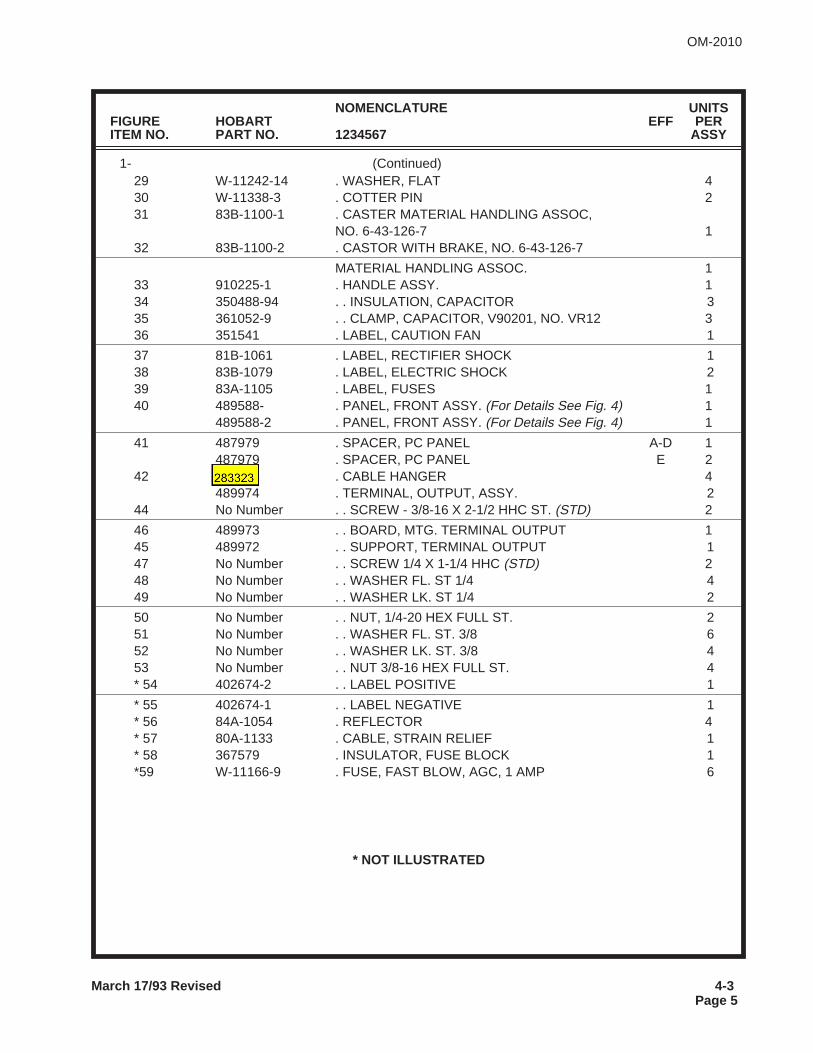
NOMENCLATURE UNITSFIGURE HOBART EFF PERITEM NO. PART NO. 1234567 ASSY
1- (Continued)29 W-11242-14 . WASHER, FLAT 430 W-11338-3 . COTTER PIN 231 83B-1100-1 . CASTER MATERIAL HANDLING ASSOC,
NO. 6-43-126-7 132 83B-1100-2 . CASTOR WITH BRAKE, NO. 6-43-126-7
MATERIAL HANDLING ASSOC. 133 910225-1 . HANDLE ASSY. 134 350488-94 . . INSULATION, CAPACITOR 335 361052-9 . . CLAMP, CAPACITOR, V90201, NO. VR12 336 351541 . LABEL, CAUTION FAN 1
37 81B-1061 . LABEL, RECTIFIER SHOCK 138 83B-1079 . LABEL, ELECTRIC SHOCK 239 83A-1105 . LABEL, FUSES 140 489588- . PANEL, FRONT ASSY. (For Details See Fig. 4) 1
489588-2 . PANEL, FRONT ASSY. (For Details See Fig. 4) 1
41 487979 . SPACER, PC PANEL A-D 1487979 . SPACER, PC PANEL E 2
42 487964 . CABLE HANGER 4489974 . TERMINAL, OUTPUT, ASSY. 2
44 No Number . . SCREW - 3/8-16 X 2-1/2 HHC ST. (STD) 2
46 489973 . . BOARD, MTG. TERMINAL OUTPUT 145 489972 . . SUPPORT, TERMINAL OUTPUT 147 No Number . . SCREW 1/4 X 1-1/4 HHC (STD) 248 No Number . . WASHER FL. ST 1/4 449 No Number . . WASHER LK. ST 1/4 2
50 No Number . . NUT, 1/4-20 HEX FULL ST. 251 No Number . . WASHER FL. ST. 3/8 652 No Number . . WASHER LK. ST. 3/8 453 No Number . . NUT 3/8-16 HEX FULL ST. 4* 54 402674-2 . . LABEL POSITIVE 1
* 55 402674-1 . . LABEL NEGATIVE 1* 56 84A-1054 . REFLECTOR 4* 57 80A-1133 . CABLE, STRAIN RELIEF 1* 58 367579 . INSULATOR, FUSE BLOCK 1*59 W-11166-9 . FUSE, FAST BLOW, AGC, 1 AMP 6
* NOT ILLUSTRATED
March 17/93 Revised 4-3Page 5
OM-2010
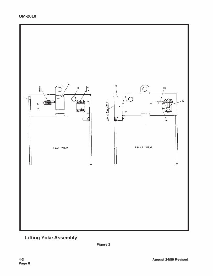
Lifting Yoke AssemblyFigure 2
OM-2010
4-3 August 24/89 RevisedPage 6
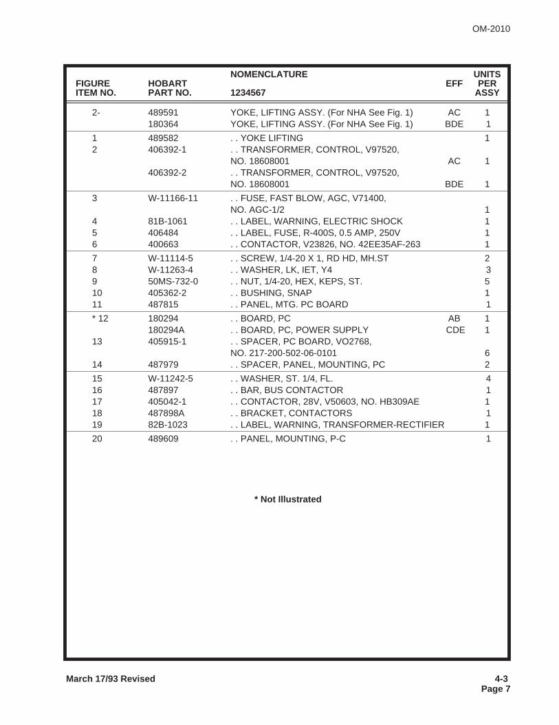
NOMENCLATURE UNITSFIGURE HOBART EFF PERITEM NO. PART NO. 1234567 ASSY
2- 489591 YOKE, LIFTING ASSY. (For NHA See Fig. 1) AC 1180364 YOKE, LIFTING ASSY. (For NHA See Fig. 1) BDE 1
1 489582 . . YOKE LIFTING 12 406392-1 . . TRANSFORMER, CONTROL, V97520,
NO. 18608001 AC 1406392-2 . . TRANSFORMER, CONTROL, V97520,
NO. 18608001 BDE 1
3 W-11166-11 . . FUSE, FAST BLOW, AGC, V71400,NO. AGC-1/2 1
4 81B-1061 . . LABEL, WARNING, ELECTRIC SHOCK 15 406484 . . LABEL, FUSE, R-400S, 0.5 AMP, 250V 16 400663 . . CONTACTOR, V23826, NO. 42EE35AF-263 1
7 W-11114-5 . . SCREW, 1/4-20 X 1, RD HD, MH.ST 28 W-11263-4 . . WASHER, LK, IET, Y4 39 50MS-732-0 . . NUT, 1/4-20, HEX, KEPS, ST. 510 405362-2 . . BUSHING, SNAP 111 487815 . . PANEL, MTG. PC BOARD 1
* 12 180294 . . BOARD, PC AB 1180294A . . BOARD, PC, POWER SUPPLY CDE 1
13 405915-1 . . SPACER, PC BOARD, VO2768,NO. 217-200-502-06-0101 6
14 487979 . . SPACER, PANEL, MOUNTING, PC 2
15 W-11242-5 . . WASHER, ST. 1/4, FL. 416 487897 . . BAR, BUS CONTACTOR 117 405042-1 . . CONTACTOR, 28V, V50603, NO. HB309AE 118 487898A . . BRACKET, CONTACTORS 119 82B-1023 . . LABEL, WARNING, TRANSFORMER-RECTIFIER 1
20 489609 . . PANEL, MOUNTING, P-C 1
* Not Illustrated
March 17/93 Revised 4-3Page 7
OM-2010
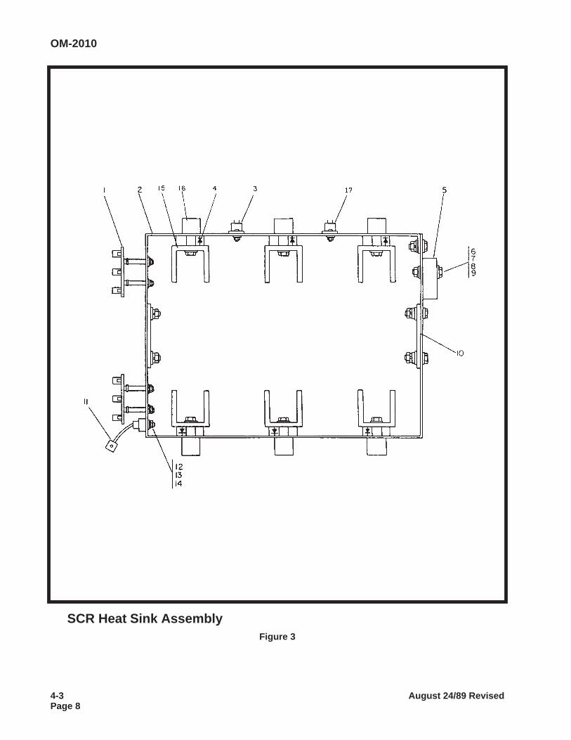
SCR Heat Sink AssemblyFigure 3
OM-2010
4-3 August 24/89 RevisedPage 8
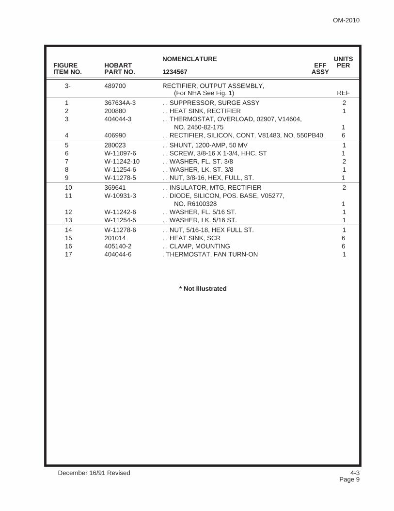
NOMENCLATURE UNITSFIGURE HOBART EFF PERITEM NO. PART NO. 1234567 ASSY
3- 489700 RECTIFIER, OUTPUT ASSEMBLY,(For NHA See Fig. 1) REF
1 367634A-3 . . SUPPRESSOR, SURGE ASSY 22 200880 . . HEAT SINK, RECTIFIER 13 404044-3 . . THERMOSTAT, OVERLOAD, 02907, V14604,
NO. 2450-82-175 14 406990 . . RECTIFIER, SILICON, CONT. V81483, NO. 550PB40 6
5 280023 . . SHUNT, 1200-AMP, 50 MV 16 W-11097-6 . . SCREW, 3/8-16 X 1-3/4, HHC. ST 17 W-11242-10 . . WASHER, FL. ST. 3/8 28 W-11254-6 . . WASHER, LK, ST. 3/8 19 W-11278-5 . . NUT, 3/8-16, HEX, FULL, ST. 1
10 369641 . . INSULATOR, MTG, RECTIFIER 211 W-10931-3 . . DIODE, SILICON, POS. BASE, V05277,
NO. R6100328 112 W-11242-6 . . WASHER, FL. 5/16 ST. 113 W-11254-5 . . WASHER, LK. 5/16 ST. 1
14 W-11278-6 . . NUT, 5/16-18, HEX FULL ST. 115 201014 . . HEAT SINK, SCR 616 405140-2 . . CLAMP, MOUNTING 617 404044-6 . THERMOSTAT, FAN TURN-ON 1
* Not Illustrated
OM-2010
December 16/91 Revised 4-3Page 9
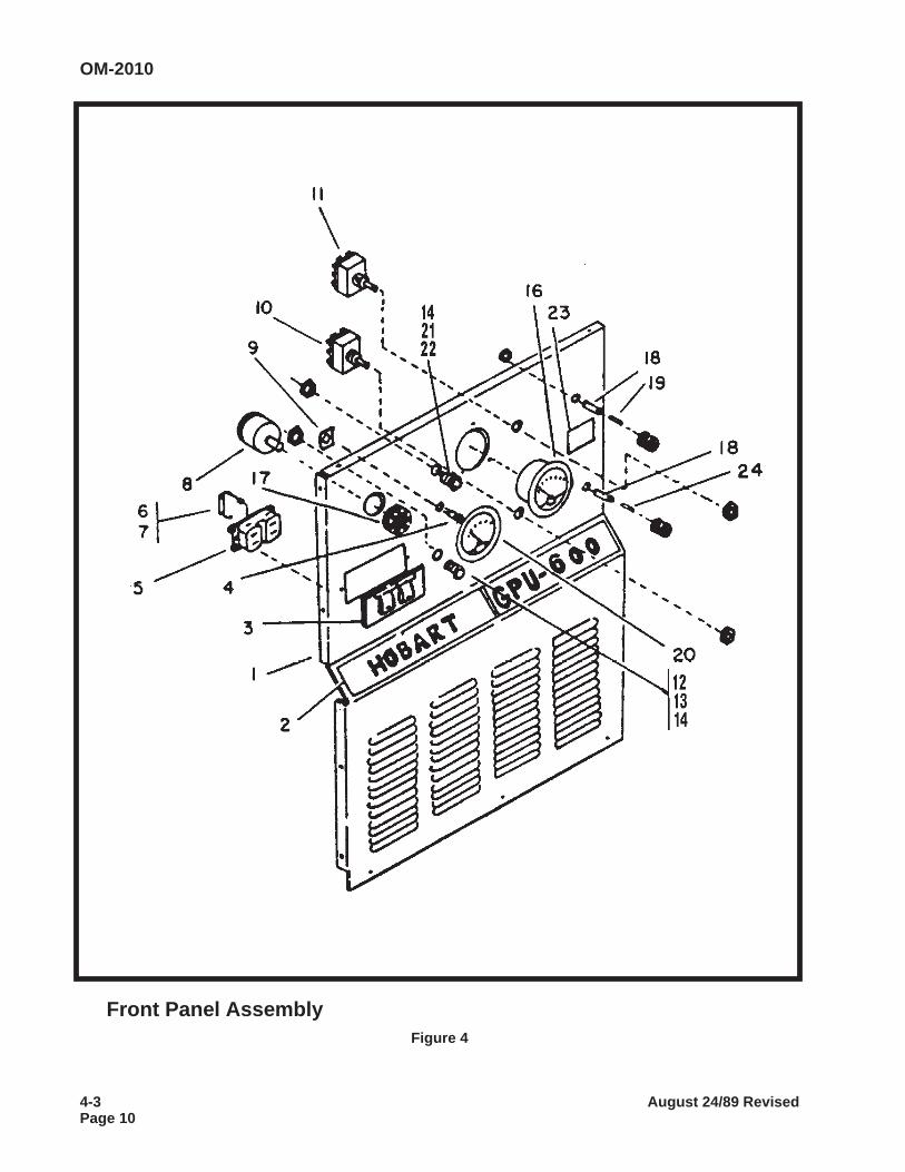
Front Panel AssemblyFigure 4
OM-2010
4-3 August 24/89 RevisedPage 10
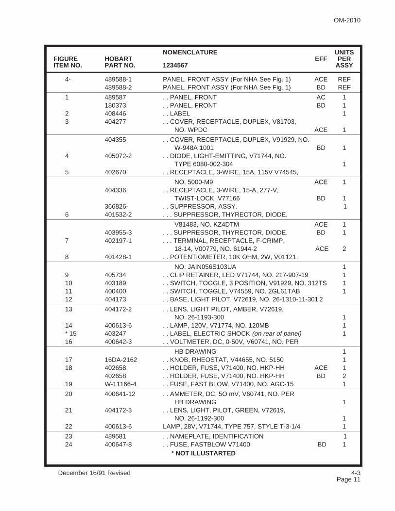
NOMENCLATURE UNITSFIGURE HOBART EFF PERITEM NO. PART NO. 1234567 ASSY
4- 489588-1 PANEL, FRONT ASSY (For NHA See Fig. 1) ACE REF489588-2 PANEL, FRONT ASSY (For NHA See Fig. 1) BD REF
1 489587 . . PANEL, FRONT AC 1180373 . . PANEL, FRONT BD 1
2 408446 . . LABEL 13 404277 . . COVER, RECEPTACLE, DUPLEX, V81703,
NO. WPDC ACE 1
404355 . . COVER, RECEPTACLE, DUPLEX, V91929, NO.W-948A 1001 BD 1
4 405072-2 . . DIODE, LIGHT-EMITTING, V71744, NO.TYPE 6080-002-304 1
5 402670 . . RECEPTACLE, 3-WIRE, 15A, 115V V74545,
NO. 5000-M9 ACE 1404336 . . RECEPTACLE, 3-WIRE, 15-A, 277-V,
TWIST-LOCK, V77166 BD 1366826- . . SUPPRESSOR, ASSY. 1
6 401532-2 . . . SUPPRESSOR, THYRECTOR, DIODE,
V81483, NO. KZ4DTM ACE 1403955-3 . . . SUPPRESSOR, THYRECTOR, DIODE, BD 1
7 402197-1 . . . TERMINAL, RECEPTACLE, F-CRIMP,18-14, V00779, NO. 61944-2 ACE 2
8 401428-1 . . POTENTIOMETER, 10K OHM, 2W, V01121,
NO. JAIN056S103UA 19 405734 . . CLIP RETAINER, LED V71744, NO. 217-907-19 110 403189 . . SWITCH, TOGGLE, 3 POSITION, V91929, NO. 312TS 111 400400 . . SWITCH, TOGGLE, V74559, NO. 2GL61TAB 112 404173 . . BASE, LIGHT PILOT, V72619, NO. 26-1310-11-301 2
13 404172-2 . . LENS, LIGHT PILOT, AMBER, V72619,NO. 26-1193-300 1
14 400613-6 . . LAMP, 120V, V71774, NO. 120MB 1* 15 403247 . . LABEL, ELECTRIC SHOCK (on rear of panel) 116 400642-3 . . VOLTMETER, DC, 0-50V, V60741, NO. PER
HB DRAWING 117 16DA-2162 . . KNOB, RHEOSTAT, V44655, NO. 5150 118 402658 . . HOLDER, FUSE, V71400, NO. HKP-HH ACE 1
402658 . . HOLDER, FUSE, V71400, NO. HKP-HH BD 219 W-11166-4 . . FUSE, FAST BLOW, V71400, NO. AGC-15 1
20 400641-12 . . AMMETER, DC, 5O mV, V60741, NO. PERHB DRAWING 1
21 404172-3 . . LENS, LIGHT, PILOT, GREEN, V72619,NO. 26-1192-300 1
22 400613-6 LAMP, 28V, V71744, TYPE 757, STYLE T-3-1/4 1
23 489581 . . NAMEPLATE, IDENTIFICATION 124 400647-8 . . FUSE, FASTBLOW V71400 BD 1
* NOT ILLUSTARTED
OM-2010
December 16/91 Revised 4-3Page 11

This page intentionally left blank.
OM-2010
4-3 August 24/89 RevisedPage 12
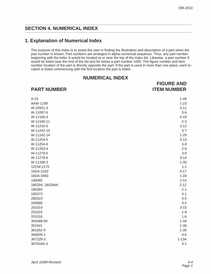
SECTION 4. NUMERICAL INDEX
1. Explanation of Numerical Index
The purpose of this index is to assist the user in finding the illustration and description of a part when thepart number is known. Part numbers are arranged in alpha-numerical sequence. Thus, any part numberbeginning with the letter A would be located at or near the top of the index list. Likewise, a part number 9would be listed near the end of the list and far below a part number 1000. The figure number and itemnumber location of the part is directly opposite the part. If the part is used in more than one place, each lo-cation is listed commencing with the first location the part is listed.
NUMERICAL INDEXFIGURE AND
PART NUMBER ITEM NUMBER
A-25 1-49AAW-1199 1-23W-10931-3 3-11W-11097-6 3-6W-11166-4 4-19W-11166-11 2-3W-11242-6 3-12W-11242-10 3-7W-11242-14 1-29W-11254-5 3-13W-11254-6 3-8W-11263-4 2-8W-11278-5 3-9W-11278-6 3-14W-11338-3 1-3012CW-2170 1-116DA-2162 4-1716DA-3493 1-24180065 1-14180294, 180294A 2-12180364 2-1180373 4-1280023 3-5200880 3-2201014 3-15201015 1-9201016 1-6350488-94 1-34351541 1-36361052-9 1-35366826-1 4-6367229-3 1-13A367634A-3 3-1
OM-2010
April 10/89 Revised 4-4Page 1
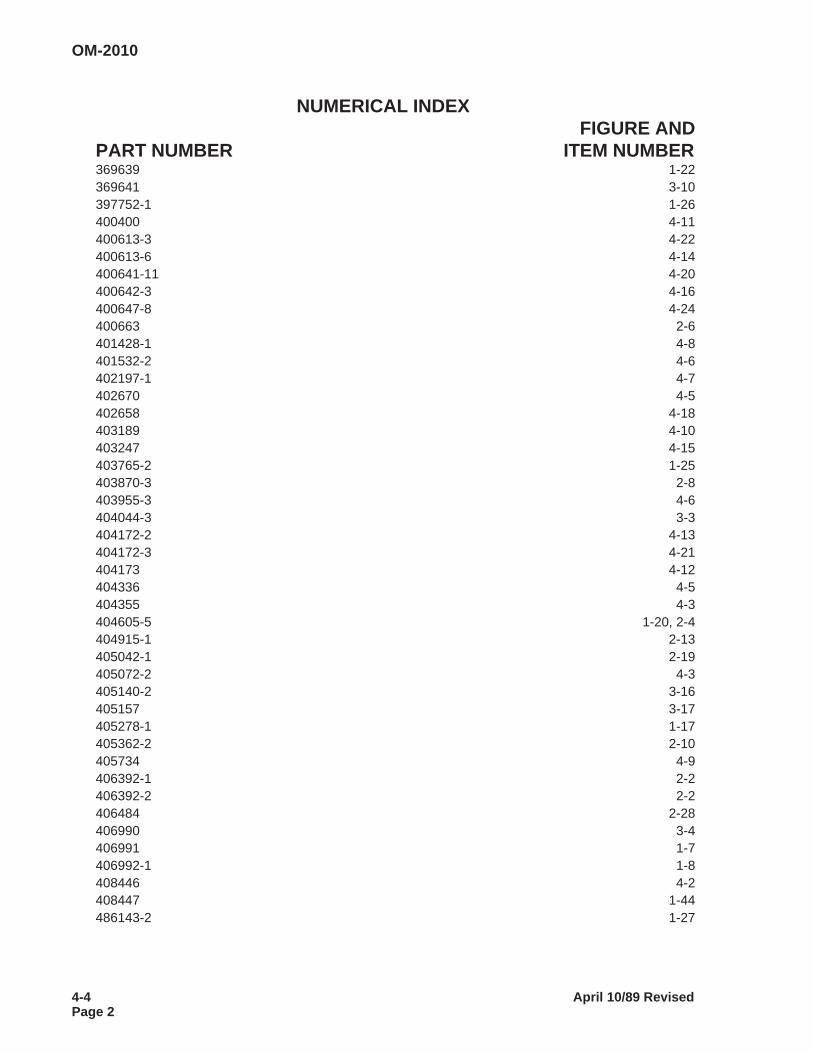
NUMERICAL INDEXFIGURE AND
PART NUMBER ITEM NUMBER369639 1-22369641 3-10397752-1 1-26400400 4-11400613-3 4-22400613-6 4-14400641-11 4-20400642-3 4-16400647-8 4-24400663 2-6401428-1 4-8401532-2 4-6402197-1 4-7402670 4-5402658 4-18403189 4-10403247 4-15403765-2 1-25403870-3 2-8403955-3 4-6404044-3 3-3404172-2 4-13404172-3 4-21404173 4-12404336 4-5404355 4-3404605-5 1-20, 2-4404915-1 2-13405042-1 2-19405072-2 4-3405140-2 3-16405157 3-17405278-1 1-17405362-2 2-10405734 4-9406392-1 2-2406392-2 2-2406484 2-28406990 3-4406991 1-7406992-1 1-8408446 4-2408447 1-44486143-2 1-27
OM-2010
4-4 April 10/89 RevisedPage 2
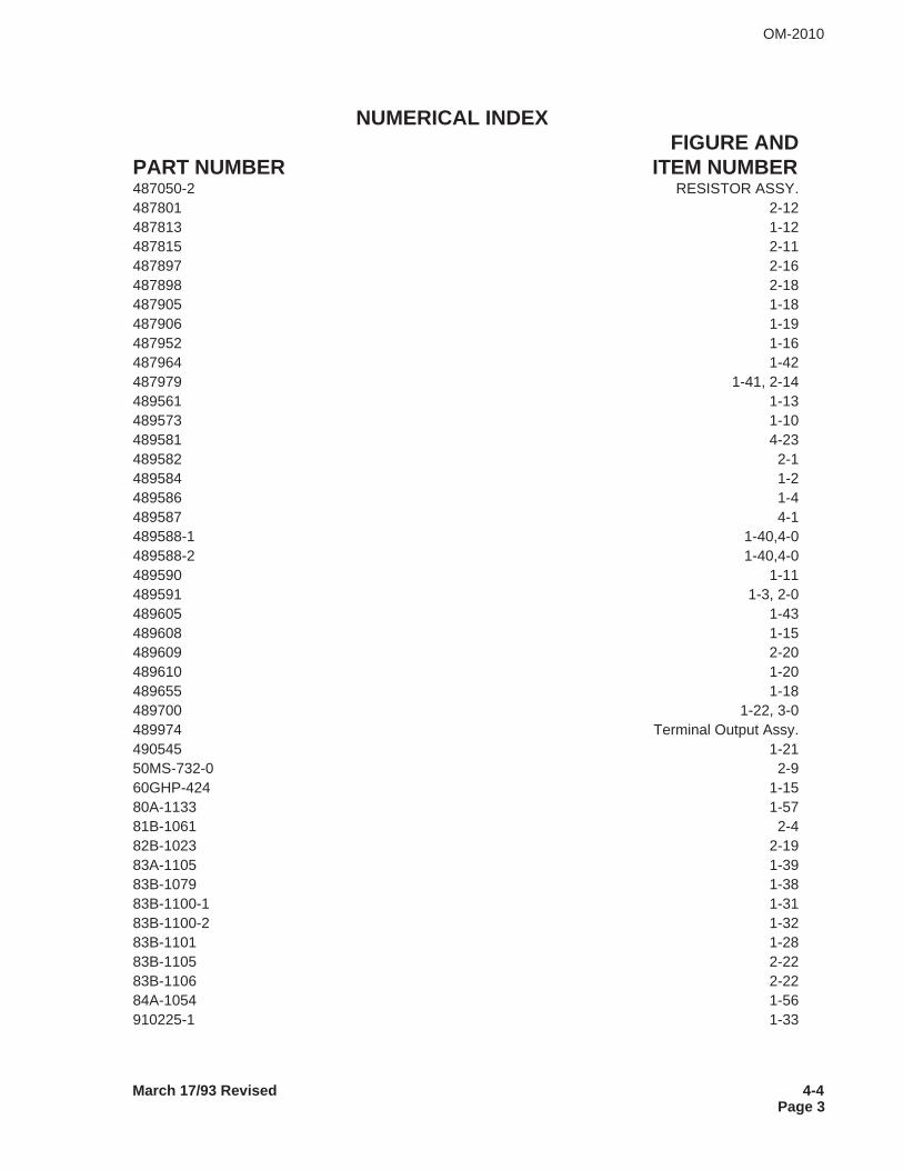
NUMERICAL INDEXFIGURE AND
PART NUMBER ITEM NUMBER487050-2 RESISTOR ASSY.487801 2-12487813 1-12487815 2-11487897 2-16487898 2-18487905 1-18487906 1-19487952 1-16487964 1-42487979 1-41, 2-14489561 1-13489573 1-10489581 4-23489582 2-1489584 1-2489586 1-4489587 4-1489588-1 1-40,4-0489588-2 1-40,4-0489590 1-11489591 1-3, 2-0489605 1-43489608 1-15489609 2-20489610 1-20489655 1-18489700 1-22, 3-0489974 Terminal Output Assy.490545 1-2150MS-732-0 2-960GHP-424 1-1580A-1133 1-5781B-1061 2-482B-1023 2-1983A-1105 1-3983B-1079 1-3883B-1100-1 1-3183B-1100-2 1-3283B-1101 1-2883B-1105 2-2283B-1106 2-2284A-1054 1-56910225-1 1-33
March 17/93 Revised 4-4Page 3
OM-2010

This page intentionally left blank.
OM-2010
4-4 April 10/89 RevisedPage 4

CHAPTER 5. OPTIONAL EQUIPMENT
Optional Equipment available for use with GPU-400 is listed below.
OPTION PART No. MANUAL No.
Kit, Riser 284535 TO-231
December 17/93 Revised 5-0Page 1
OM-2010

This page intentionally left blank
OM-2010
5-0 April 10/89 RevisedPage 2

CHAPTER 6. MANUFACTURER’SLITERATURE
DIAGRAMS FOR 6883-1
489595 Schematic489596 Connection489594 Voltage Changeover
DIAGRAMS FOR 6883-2
180368 Schematic180369 Connection180367 Voltage Changeover
DIAGRAMS FOR 6883A
489595 Schematic489596 Connection181566 Voltage Changeover
OM-2010
Apri l 10/89 Revised 6-0Page 1

This page intentionally left blank.
OM-2010
6-0 April 10/89 RevisedPage 2
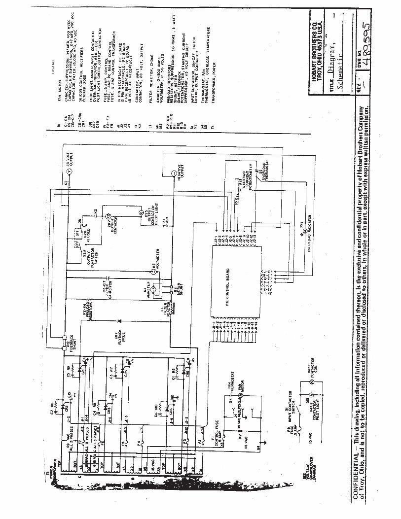

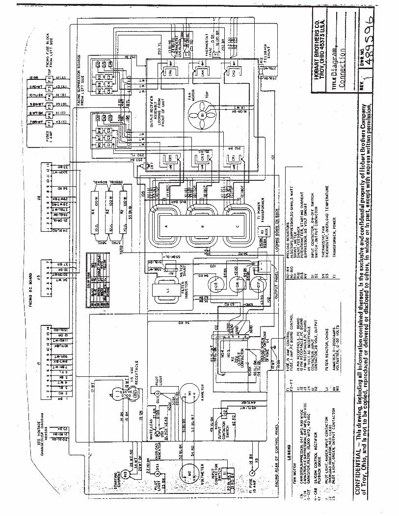

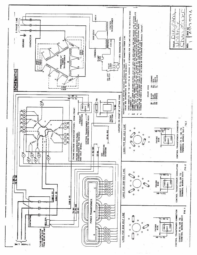

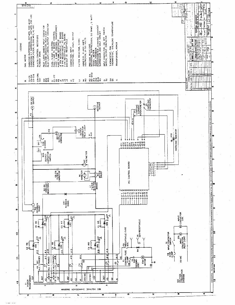

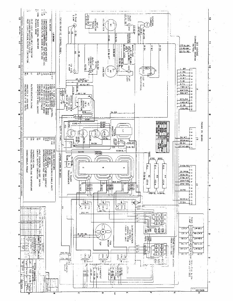

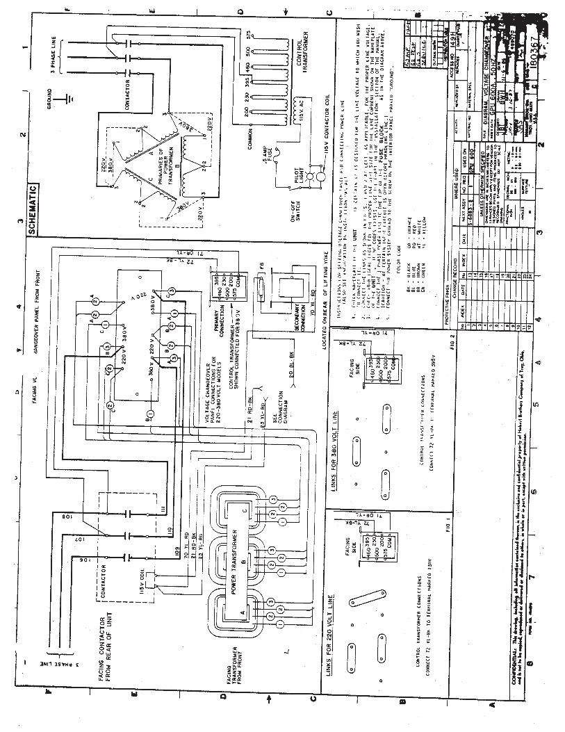

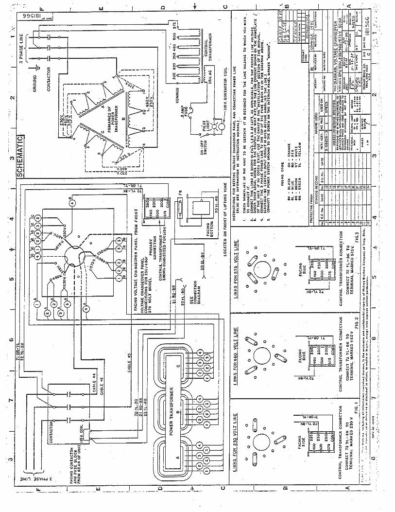


UNUSUAL SERVICE CONDITIONS
This information is a general guideline and cannot cover all possible conditions of equipment use. Thespecific local environments may be dependent upon conditions beyond the manufacturer’s control. Themanufacturer should be consulted if any unusual conditions of use exist which may affect the physicalcondition or operation of the equipment.
Among such conditions are:
1. Exposure to:
A. Combustible, explosive, abrasive or conducting dusts.
B. Environments where the accumulation of lint or excessive dirt will interfere with normal ventilation.
C. Chemical fumes, flammable or explosive gases.
D. Nuclear radiation.
E. Steam, salt-laden air, or oil vapor.
F. Damp or very dry locations, radiant heat, vermin infestation, or atmospheres conducive to fungusgrowth.
G. Abnormal shock, vibration or mechanical loading from external sources during equipment opera-tion.
H. Abnormal axial or side thrust imposed on rotating equipment shafts.
I. Low and/or high ambient temperatures.
J. High electromagnetic fields.
2. Operation at:
A. Voltages above or below rated voltage.
B. Speeds other than rated speed.
C. Frequency other than rated frequency.
D. Standstill with rotating equipment windings energized.
E. Unbalanced voltages.
F. Operation at loads greater than rated.
3. Operation where low acoustical noise levels are required.
4. Operation with:
A. Improper fuel, lubricants or coolant.
B. Parts or elements unauthorized by the manufacturer.
C. Unauthorized modifications.
5. Operation in poorly ventilated areas.

This page intentionally left blank