Embed Size (px)
Citation preview

__________________________________________________________________________________ DESMI Pumping Technology A/S Tagholm 1
9400 Nørresundby – Denmark Tel: +45 96 32 81 11 Fax: +45 98 17 54 99
E-mail: [email protected]
www.desmi.com
OPERATION AND MAINTENANCE INSTRUCTIONS
DESMI vertical "in-line" centrifugal pump
NSL Compact Spacer
DESMI Pumping Technology A/S Tagholm 1 – DK-9400 Nørresundby – Denmark
Tel.: +45 96 32 81 11
Fax: +45 98 17 54 99 E-mail: [email protected]
Internet: www.desmi.com
Manual: T1479
Language:
English
Revision: E (03/19)
Specialpumpe nr. .................
__________________________________________________________________________________ DESMI Pumping Technology A/S Tagholm 1
9400 Nørresundby – Denmark Tel: +45 96 32 81 11 Fax: +45 98 17 54 99
E-mail: [email protected]
www.desmi.com
Table of Contents:
1. PRODUCT DESCRIPTION ............................................................................................................................... 1
1.1 DELIVERY ............................................................................................................................................................. 1
2. TECHNICAL DATA ......................................................................................................................................... 1
2.1 EXPLANATION OF THE TYPE NUMBER ................................................................................................................. 1 2.2 TECHNICAL DESCRIPTION .................................................................................................................................... 2 3.1 MOUNTING/FASTENING ..................................................................................................................................... 4 3.2 WIRING ................................................................................................................................................................ 4
4. TRANSPORT/STORAGE ................................................................................................................................. 4
5. DISMANTLING .............................................................................................................................................. 5
5.1 ACCESS TO IMPELLER ........................................................................................................................................... 5 5.2 DISMANTLING SHAFT SEAL .................................................................................................................................. 5 5.3 DISMANTLING SEAT ............................................................................................................................................. 5 5.4 DISMANTLING BEARING ...................................................................................................................................... 6 5.5 INSPECTION ......................................................................................................................................................... 6
6. ASSEMBLING ................................................................................................................................................ 6
6.1 FITTING SEALING RINGS ...................................................................................................................................... 6 6.2 FITTING BEARING ................................................................................................................................................ 6 6.3 FITTING WATER DEFLECTOR ................................................................................................................................ 6 6.4 FITTING SHAFT SEAL ............................................................................................................................................ 6 6.5 FITTING IMPELLER ............................................................................................................................................... 7 6.6 FITTING SHAFT SEAL COVER ................................................................................................................................ 7 6.7 FITTING COUPLING .............................................................................................................................................. 7 6.8 SHAFT .................................................................................................................................................................. 8
7. FROST PROTECTION ..................................................................................................................................... 8
8. DISMANTLING .............................................................................................................................................. 8
9. START-UP..................................................................................................................................................... 8
9.1 START-UP ............................................................................................................................................................. 9
10. SYSTEM BALANCING ................................................................................................................................... 9
11. INSPECTION AND MAINTENANCE ............................................................................................................. 10
11.1 DRAINING THE PUMP ...................................................................................................................................... 10 11.2 BEARING ......................................................................................................................................................... 10
12. REPAIRS ................................................................................................................................................... 12
12.1 ORDERING SPARE PARTS ................................................................................................................................. 12
13. OPERATING DATA .................................................................................................................................... 12
14. EU DECLARATION OF CONFORMITY .......................................................................................................... 13
15. ASSEMBLY DRAWING Ø 215/265 ............................................................................................................... 14
16. SPARE PARTS LIST Ø 215/265 .................................................................................................................... 14
17. ASSEMBLY DRAWING Ø 330/415 WITH LIGHT BEARING HOUSING .............................................................. 15

__________________________________________________________________________________ DESMI Pumping Technology A/S Tagholm 1
9400 Nørresundby – Denmark Tel: +45 96 32 81 11 Fax: +45 98 17 54 99
E-mail: [email protected]
www.desmi.com
19. ASSEMBLY DRAWING Ø 330/415 WITH HEAVY BEARING HOUSING ............................................................ 16
20. SPARE PARTS LIST Ø 330/415 WITH HEAVY BEARING HOUSING .................................................................. 16
21. DIMENSIONAL SKETCH Ø 215/265 ............................................................................................................. 17
22. DIMENSIONAL SKETCH Ø 330/415 ............................................................................................................. 18
____________________________________________________________________________________
DESMI Pumping Technology A/S 1 Tagholm 1
9400 Nørresundby – Denmark Tel: +45 96 32 81 11 Fax: +45 98 17 54 99
E-mail: [email protected]
www.desmi.com
1. PRODUCT DESCRIPTION
These operation and maintenance instructions apply to the DESMI NSL Compact Spacer pump. The pump is a single-stage vertical "in-line" centrifugal pump (i.e. horizontal inlet and outlet on the same line) equipped with stainless steel shaft, mechanical shaft seal, and closed impeller. The pump is suitable for the pumping of liquids with temperatures up to 80oC. With special shaft seal up to 120oC. Max. working pressure and number of revolutions are indicated under Operating Data. The pump is particularly suitable for the pumping of water in connection with cooling systems, cooling of diesel engines, as bilge pumps, ballast pumps, fire pumps, brine pumps, pumps for irrigation, fish farms, water works, district heating, salvage corps, army and navy, etc. The descriptions in the operation and maintenance instructions are divided into two parts covering the groups ø215/265 and ø330/415, as the designs of these two groups are different. The numbers refer to the standard impeller diameter of the pump. E.g.: ø215/265: Pumps with ø215 or ø265 impellers: The back of the impeller is equipped with relief blades to reduce the load on the bearings. The line through inlet and outlet is flush with the centre line of the shaft. ø330/415: Pumps with ø330 and ø415 impellers: The back and the front of the impeller are equipped with sealing rings and relief holes to reduce the load on the bearings. The pump inlet and outlet are tangential i.e. the line through inlet and outlet is offset in relation to the centre line of the shaft.
1.1 DELIVERY
- Check on delivery that the shipment is complete and undamaged. - Defects and damages, if any, to be reported to the carrier and the supplier immediately in order that a claim can be advanced.
2. TECHNICAL DATA
The pumps are manufactured in various material combinations which appear from the type number on the name plate. See below.
2.1 EXPLANATION OF THE TYPE NUMBER
All the NSL pumps are provided with a name plate. The type number indicated on the name plate is built up as follows:
NSLXXX-YYY-MR-Z XXX: Pressure branch diameter, YYY: Standard impeller diameter M: The material combination of the pump. R: The assembly combination of the pump. Z: Other variants

____________________________________________________________________________________
DESMI Pumping Technology A/S 2 Tagholm 1
9400 Nørresundby – Denmark Tel: +45 96 32 81 11 Fax: +45 98 17 54 99
E-mail: [email protected]
www.desmi.com
M may be the following:
A: Casing and shaft seal cover : Cast iron + cast iron alloy. Impeller and sealing rings: Bronze B: Casing and shaft seal cover : Cast iron + cast iron alloy. Impeller and sealing rings: Stainless. C: All cast iron D: Casing and shaft seal cover: Bronze or NiAlBz. Impeller and sealing rings: NiAlBz or Stainless Steel. E: Special materials U: Nonmagnetic material The pumps can be delivered in other material combinations according to agreement with the supplier. R may be the following: 02: Monobloc, with bearing in the pump 12: Monobloc, without bearing in the pump 13: Spacer, light bearing housing 14: Spacer, heavy bearing housing 15: Spacer, heavy bearing housing and heavy motor bracket (special motor bracket) 16: Compact spacer Z may be the following: i : PN16 flanges j : PN25 flanges k : Special flange l : Other shaft seal m : BS flanges n : ANSI flanges o : Shockproof design p : Other design q : JIS flanges Any use of the pump is to be evaluated on the basis of the materials used in the pump. In case of doubt, contact the supplier. Pumps in material combinations A and C are primarily used for fresh water. Pumps in material combination D and E are primarily used for seawater. If the pumps are designed for special purposes the following is to be indicated: Pump No. : Pump type : Application : Comment :
2.2 TECHNICAL DESCRIPTION
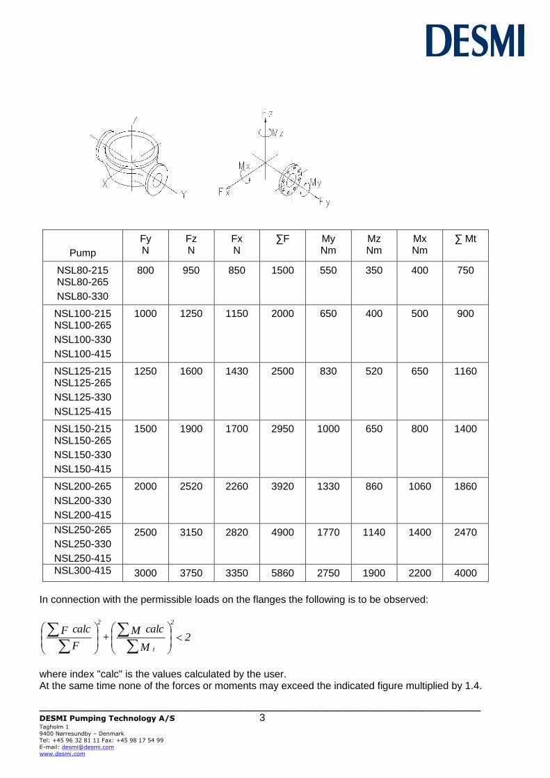
The noise level indicated is the airborne noise including the motor. The noise depends on the motor type supplied, as the noise from the pump can be calculated as the noise level of the motor + 2dB(A). The noise level is for pumps with electric motors. The capacity of the pump appears from the name plate on the pump. If the pump has been delivered without motor, the pump capacity is to be indicated on the plate when mounting the motor. The permissible loads on the flanges appear from the following table. The values apply to standard pumps in bronze (Rg5) and cast iron (GG20). As to pumps in SG iron (GGG40) the values are to be increased by factor 1.5.
____________________________________________________________________________________
DESMI Pumping Technology A/S 3 Tagholm 1
9400 Nørresundby – Denmark Tel: +45 96 32 81 11 Fax: +45 98 17 54 99
E-mail: [email protected]
www.desmi.com
Pump
Fy N
Fz N
Fx N
∑F
My Nm
Mz Nm
Mx Nm
∑ Mt
NSL80-215 NSL80-265
NSL80-330
800
950
850
1500
550
350
400
750
NSL100-215 NSL100-265
NSL100-330
NSL100-415
1000
1250
1150
2000
650
400
500
900
NSL125-215 NSL125-265
NSL125-330
NSL125-415
1250
1600
1430
2500
830
520
650
1160
NSL150-215 NSL150-265
NSL150-330
NSL150-415
1500
1900
1700
2950
1000
650
800
1400
NSL200-265
NSL200-330
NSL200-415
2000
2520
2260
3920
1330
860
1060
1860
NSL250-265
NSL250-330
NSL250-415
2500
3150
2820
4900
1770
1140
1400
2470
NSL300-415
3000
3750
3350
5860
2750
1900
2200
4000
In connection with the permissible loads on the flanges the following is to be observed:
2 M
calcM+
F
calcF
t
2
2
where index "calc" is the values calculated by the user. At the same time none of the forces or moments may exceed the indicated figure multiplied by 1.4.
____________________________________________________________________________________
DESMI Pumping Technology A/S 4 Tagholm 1
9400 Nørresundby – Denmark Tel: +45 96 32 81 11 Fax: +45 98 17 54 99
E-mail: [email protected]
www.desmi.com
3. INSTALLATION
3.1 MOUNTING/FASTENING
The pump should be mounted and fastened on a solid base plate with a flat and horizontal surface to avoid distortion. The max. permissible loads on the flanges stated in paragraph 2.2 are to be observed.
At installations pumping hot or very cold liquids, the operator must be aware that it is dangerous
to touch the pump surface and, consequently, he must take the necessary safety measures.
3.2 WIRING
Wiring to be carried out by authorised skilled workmen according to the rules and regulations in force.
4. TRANSPORT/STORAGE
The weights of the pumps in A and D combination (without motor) are stated in the following table, and the pumps are to be lifted as shown below. The D12-combination is as standard only available in ø330/415.
Pump
Weight in kg A16 / D16
comb. incl. base plate
Pump
Weight in kg A16 / D16
comb. incl. base plate
NSL80-215 176 / 191 NSL150-215 217 / 241
NSL80-265 184 / 201 NSL150-265 221 / 246
NSL80-330 276 / 281 NSL150-330 369 / 359
NSL100-215 187 / 204 NSL150-415 459 / 479
NSL100-265 185 / 202 NSL200-265 256 / 289
NSL100-330 291 / 297 NSL200-330 439 / 424
NSL100-415 379 / 399 NSL200-415 554 / 574
NSL125-215 198 / 213 NSL250-265 335 / 375
NSL125-265 203 / 224 NSL250-330 519 / 509
NSL125-330 306 / 312 NSL250-415 634 / 639
NSL125-415 414 / 434 NSL300-415 734 / 734
The pump is to be stored in a dry area. Before shipment the pump is to be fastened securely on pallets or the like.
____________________________________________________________________________________
DESMI Pumping Technology A/S 5 Tagholm 1
9400 Nørresundby – Denmark Tel: +45 96 32 81 11 Fax: +45 98 17 54 99
E-mail: [email protected]
www.desmi.com
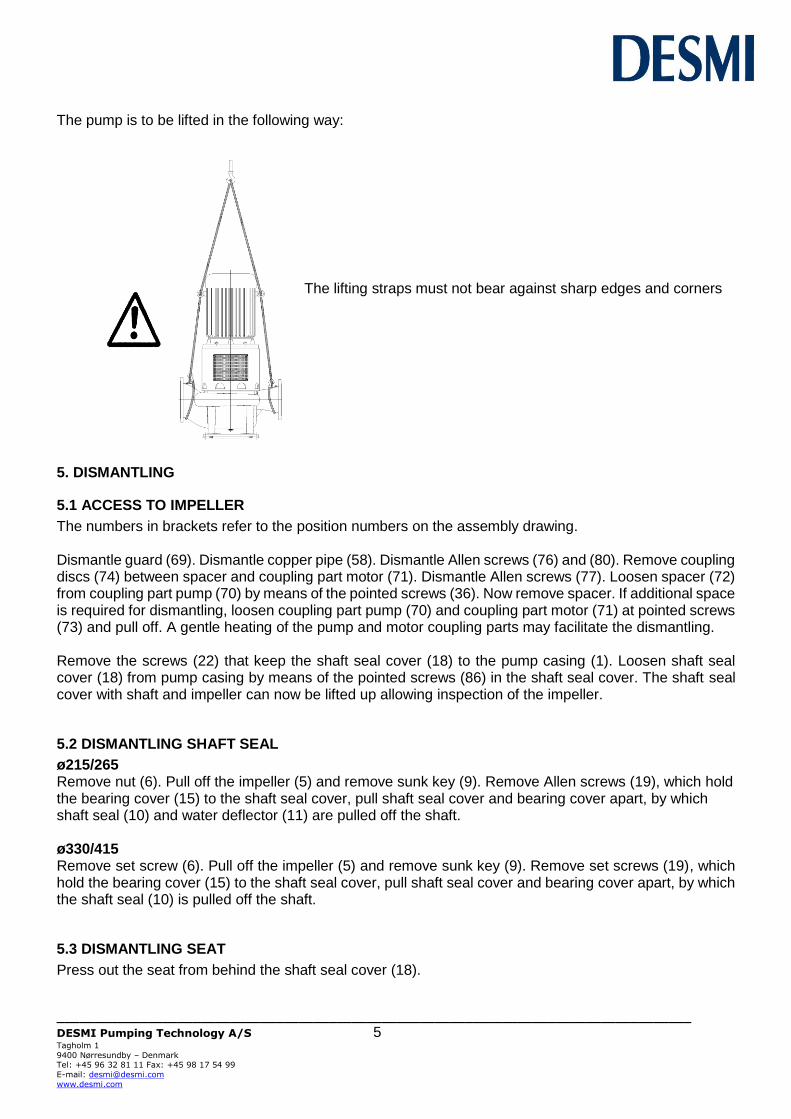
The pump is to be lifted in the following way: The lifting straps must not bear against sharp edges and corners
5. DISMANTLING
5.1 ACCESS TO IMPELLER
The numbers in brackets refer to the position numbers on the assembly drawing. Dismantle guard (69). Dismantle copper pipe (58). Dismantle Allen screws (76) and (80). Remove coupling discs (74) between spacer and coupling part motor (71). Dismantle Allen screws (77). Loosen spacer (72) from coupling part pump (70) by means of the pointed screws (36). Now remove spacer. If additional space is required for dismantling, loosen coupling part pump (70) and coupling part motor (71) at pointed screws (73) and pull off. A gentle heating of the pump and motor coupling parts may facilitate the dismantling. Remove the screws (22) that keep the shaft seal cover (18) to the pump casing (1). Loosen shaft seal cover (18) from pump casing by means of the pointed screws (86) in the shaft seal cover. The shaft seal cover with shaft and impeller can now be lifted up allowing inspection of the impeller.
5.2 DISMANTLING SHAFT SEAL
ø215/265 Remove nut (6). Pull off the impeller (5) and remove sunk key (9). Remove Allen screws (19), which hold the bearing cover (15) to the shaft seal cover, pull shaft seal cover and bearing cover apart, by which shaft seal (10) and water deflector (11) are pulled off the shaft. ø330/415 Remove set screw (6). Pull off the impeller (5) and remove sunk key (9). Remove set screws (19), which hold the bearing cover (15) to the shaft seal cover, pull shaft seal cover and bearing cover apart, by which the shaft seal (10) is pulled off the shaft.
5.3 DISMANTLING SEAT
Press out the seat from behind the shaft seal cover (18).
____________________________________________________________________________________
DESMI Pumping Technology A/S 6 Tagholm 1
9400 Nørresundby – Denmark Tel: +45 96 32 81 11 Fax: +45 98 17 54 99
E-mail: [email protected]
www.desmi.com
5.4 DISMANTLING BEARING
Before dismantling bearing, remove ring lock (12). Pull shaft with coupling out of the bearing cover and press out the bearing.
5.5 INSPECTION
When the pump has been dismantled, check the following parts for wear and damage: - Sealing ring/impeller: Max. clearance 0.4-0.5 mm measured in radius. - Shaft seal/shaft seal cover: Check the seat for flatness and cracks.
Check the rubber parts for elasticity. - Bearings: Replace in case of wear and noise.
6. ASSEMBLING
6.1 FITTING SEALING RINGS
When fitted, the sealing ring (4) has to bear against the shoulder of the pump casing. ø330/415 When fitted the sealing ring (27) has to bear against the shoulder of the shaft seal cover (20).
6.2 FITTING BEARING
Place the support disc (14) (grease valve ring in ø330/415 with angular ball bearings) in the bearing cover and press the bearing into place in the bearing cover. Lead the shaft through the bearing cover, support disc and bearing, and press the bearing into place up against the support disc. Fit ring lock (12). ø330/415 Fit cover under bearing (26).
6.3 FITTING WATER DEFLECTOR
ø215/265 Assemble bearing cover and shaft seal cover. Lead the water deflector (11) over the shaft until it touches the shaft seal cover and then further 1-1.5 mm into the shaft seal cover. Do not fasten bearing cover and electric motor until motor and coupling have been mounted and the shaft can rotate freely without noise. ø330/415 Lead the water deflector (11) over the shaft until it touches the cover under bearing (26) and then further 1-1.5 mm towards the cover under bearing. Assemble bearing cover and shaft seal cover. Do not fasten bearing cover and electric motor until motor and coupling have been mounted and the shaft can rotate freely without noise.
6.4 FITTING SHAFT SEAL
Pay attention to the rubber type of which the shaft seal bellows has been made. Standard is NITRILE, however EPDM may also be used. EPDM will be damaged by mineral grease. For EPDM use soft soap or silicone grease. Before fitting the seat, clean the recess in the shaft seal cover. Dip the outer rubber
____________________________________________________________________________________
DESMI Pumping Technology A/S 7 Tagholm 1
9400 Nørresundby – Denmark Tel: +45 96 32 81 11 Fax: +45 98 17 54 99
E-mail: [email protected]
www.desmi.com
ring of the seat into soapy water or apply silicone grease. Now press the seat into place with the fingers and check that all parts are correctly imbedded. If it is necessary to use tools for assembling, then protect the sliding surface of the seat to prevent it from being scratched or cut. Lubricate the inner surface of the slide ring rubber bellows with soapy water and push it over the shaft. The use of a conical fitting bush as shown on the assembly drawing is recommended to avoid that the rubber bellows is cut. Push the slide ring over the shaft with the hand. If the rubber bellows is tight, use a fitting tool and take care that the slide ring is not damaged. If the carbon ring is not fixed, it is important to check that it is fitted correctly, i.e. the chamfered/lapped side is to face the seat. The carbon ring can be held by a little grease. When using soapy water on the shaft, the bellows will settle and seat in about 15 minutes, and until then tightness should not be expected. After start, check by viewing the leak hole in bearing cover/shaft seal cover that there are no leaks.
6.5 FITTING IMPELLER
Fit the sunk key in the shaft and lead the impeller towards the shoulder of the shaft. Take care that the ring at the end of the shaft seal spring locates in the recess of the impeller. Secure the impeller with washers (7 and 8) and a nut (ø215/265) or a set screw (ø330/415). Secure set screw (6) or nut (6) with a removable screw locking agent, e.g. Loctite 243 or Omnifit 40M. Tighten according to below table.
6.6 FITTING SHAFT SEAL COVER
Place the O-ring (21) between pump casing and shaft seal cover in the O-ring groove and hold it with a little grease. However, check the material of the O-ring first. As standard the material is NITRILE, but it may be EPDM which will be damaged by mineral grease. Use soft soap or silicone grease for EPDM. Fit and fasten shaft seal cover or motor bracket, mounted with the electric motor, in the pump casing. Screw the pointed screws (86) back into the shaft seal cover before tightening. Tighten the screws in the shaft seal cover according to below table. Fit copper pipe (58).
6.7 FITTING COUPLING
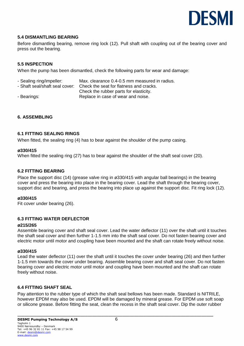
Fit sunk key (16) and motor shaft sunk key. Lead coupling part pump (70) against the shoulder of the shaft (17) and tighten by means of pointed screw (73). Mount coupling part motor (71). Do not tighten the pointed screw (73) into the coupling part motor until the remaining parts of the coupling have been mounted and tightened. Mount spacer (72) by means of Allen screws (77). Secure the screws with a removable screw locking agent. Mount coupling discs (74) and washer (78) between spacer and coupling part motor by means of Allen screws (76), pinch nuts (79) and Allen screws (80). Secure screws with a removable screw locking agent. Turn the shaft a couple of times while tightening each screw slightly until coupling discs and coupling part motor have come into place. Now tighten Allen screws and pointed screw (73) in coupling part motor. Check radial runout on the flanges, where the coupling plates are mounted, by means of a measuring gauge fixed to the motor bracket - see below drawing. After tightening-up the Allen screws (76 and 80) check that the radial runout does not exceed 0.1 mm. A larger runout may result in pump vibrations, increased bearing load and/or the impeller getting into contact with the pump sealing ring(s).
____________________________________________________________________________________
DESMI Pumping Technology A/S 8 Tagholm 1
9400 Nørresundby – Denmark Tel: +45 96 32 81 11 Fax: +45 98 17 54 99
E-mail: [email protected]
www.desmi.com
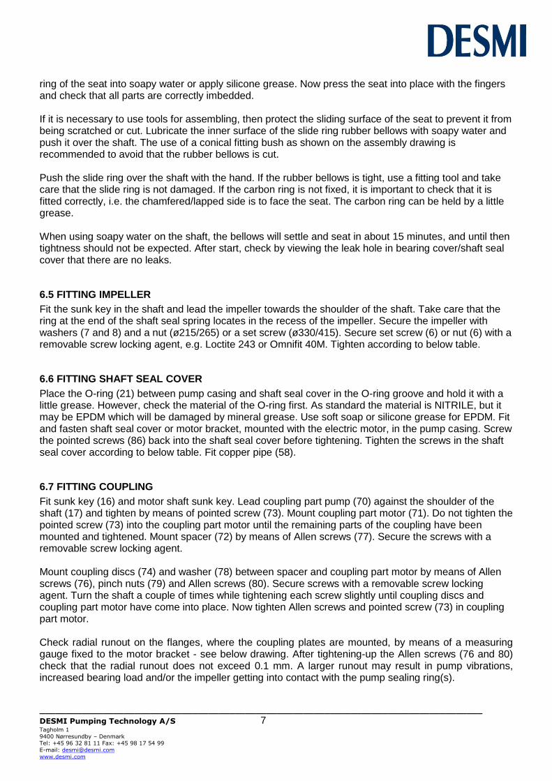
Tighten Allen screws in the coupling according to below table.
Screw dimension Moment in Nm
M8 8
M10 15
M12 27
M16 65
M20 127
6.8 SHAFT
When the pump has been assembled, check that the shaft rotates freely and without noise.
7. FROST PROTECTION
Pumps which are not in operation during frost periods are to be drained to avoid frost damage. Remove the plug (3) at the bottom to empty the pump. Alternatively, it is possible to use anti-freeze liquids in normal constructions.
8. DISMANTLING
Before dismantling the pump make sure that it has stopped. Empty the pump of liquid before it is dismantled from the piping system. If the pump has been pumping dangerous liquids you are to be
aware of this and take the necessary safety measures. If the pump has been pumping hot liquids, take great care that it is drained before it is removed from the piping system.
9. START-UP
A centrifugal pump will not function until it has been filled with liquid between the foot valve and somewhat above the impeller of the pump.
____________________________________________________________________________________
DESMI Pumping Technology A/S 9 Tagholm 1
9400 Nørresundby – Denmark Tel: +45 96 32 81 11 Fax: +45 98 17 54 99
E-mail: [email protected]
www.desmi.com
The liquid also serves as coolant for the shaft seal. In order to protect the shaft seal the pump must not run dry.
ATTENTION
For safety reasons the pump is only allowed to operate against closed discharge valve for a short time (max. 5 minutes and at a max. temperature of 80°C for standard pumps). Otherwise there is a risk of damage to the pump and, at worst, of a steam explosion. If the pump is not monitored, the installation of a safety device is recommended.
9.1 START-UP
Before starting the pump check that: - the shaft rotates freely without jarring sounds.
- the pump casing and the suction line are filled with liquid. Start the pump for a moment to check the direction of rotation. If the direction is correct (i.e. in the direction of the arrow) the pump may be started.
10. SYSTEM BALANCING
It is often difficult to calculate a manometric delivery head in advance. It is, however, decisively important to the quantity of liquid delivered. A considerably smaller delivery head than expected will increase the quantity of liquid delivered, causing increased power consumption and perhaps cavitation in pump and piping. In the pump the impeller may show signs of heavy erosion caused by cavitation (corrosion) which may at times render an impeller unfit for use in a very short time. Not unusually do similar erosions occur in pipe bends and valves elsewhere in the piping system. Therefore, after start-up, it is necessary to check either the quantity of liquid delivered or the power consumption of the pump e.g. by measuring the current intensity of the connected motor. Together with a reading of the differential pressure the quantity of water delivered can be determined against the characteristics of the pump. Should the pump not function as intended, please proceed according to the fault-finding list. Bear in mind, though, that the pump was carefully checked and tested at the factory and that the majority of faults stem from the piping system .

____________________________________________________________________________________
DESMI Pumping Technology A/S 10 Tagholm 1
9400 Nørresundby – Denmark Tel: +45 96 32 81 11 Fax: +45 98 17 54 99
E-mail: [email protected]
www.desmi.com
FAULT
CAUSE
REMEDY
The pump has no or too low capacity
1. Wrong direction of rotation
2. Piping system choked 3. The pump is choked 4. Suction line leaks Pump takes air 5. Suction lift too high 6. Pump and piping
system wrongly dimensioned
Change direction of rotation to clockwise when viewed from shaft end (the direction of the arrow) Clean or replace Clean the pump Find the leakage, repair the fault, non-return valve not submerged Check data sheet Q/H curve and NPSH or contact DESMI As 5
The pump uses too much power
1. Counter-pressure too low
2. The liquid is heavier than water 3. Foreign body in pump 4. Electric motor is running on 2 phases
Insert orifice plate or check valve/Contact DESMI Contact DESMI Dismantle the pump, remove the cause Check fuses, cable connection, and cable
The pump makes noise
1. Cavitation in pump Suction lift too high/ Suction line wrongly dimensioned/Liquid temperature too high
11. INSPECTION AND MAINTENANCE
Inspect the shaft seal for leaks at regular intervals.
- Before inspection of a pump without guard check that the pump cannot be started unintentionally. - The system is to be without pressure and drained of liquid.
- The repairman must be familiar with the type of liquid which has been pumped as well as the safety measures he is to take when handling the liquid.
11.1 DRAINING THE PUMP
When the piping system has been drained, note that there is still liquid in the pump. Remove the liquid by dismantling the pipe plug (3) at the bottom of the pump.
11.2 BEARING
ø215/265 The bearing in the 02-combination is dimensioned for a nominal life of 25,000 working hours. The bearing is lubricated for life and requires no attention but is to be replaced in case of noise or bearing wear.
____________________________________________________________________________________
DESMI Pumping Technology A/S 11 Tagholm 1
9400 Nørresundby – Denmark Tel: +45 96 32 81 11 Fax: +45 98 17 54 99
E-mail: [email protected]
www.desmi.com
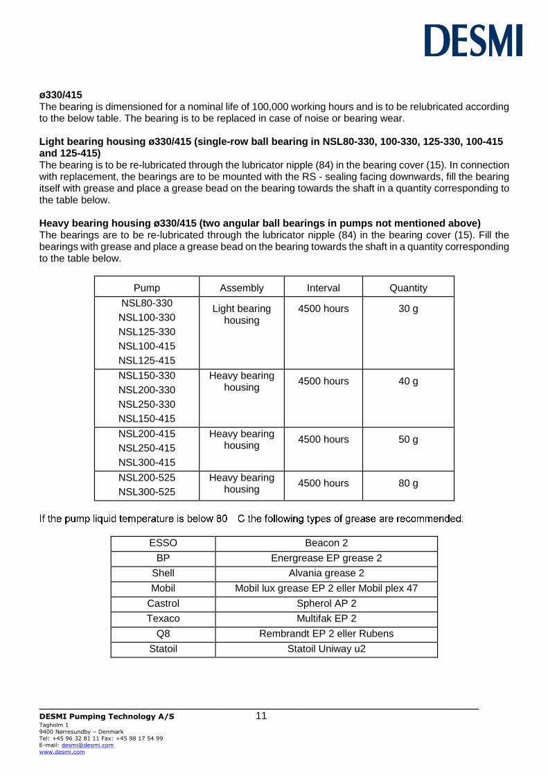
ø330/415 The bearing is dimensioned for a nominal life of 100,000 working hours and is to be relubricated according to the below table. The bearing is to be replaced in case of noise or bearing wear. Light bearing housing ø330/415 (single-row ball bearing in NSL80-330, 100-330, 125-330, 100-415 and 125-415) The bearing is to be re-lubricated through the lubricator nipple (84) in the bearing cover (15). In connection with replacement, the bearings are to be mounted with the RS - sealing facing downwards, fill the bearing itself with grease and place a grease bead on the bearing towards the shaft in a quantity corresponding to the table below. Heavy bearing housing ø330/415 (two angular ball bearings in pumps not mentioned above) The bearings are to be re-lubricated through the lubricator nipple (84) in the bearing cover (15). Fill the bearings with grease and place a grease bead on the bearing towards the shaft in a quantity corresponding to the table below.
Pump
Assembly
Interval
Quantity
NSL80-330
NSL100-330
NSL125-330
NSL100-415
NSL125-415
Light bearing
housing
4500 hours
30 g
NSL150-330
NSL200-330
NSL250-330
NSL150-415
Heavy bearing housing
4500 hours
40 g
NSL200-415
NSL250-415
NSL300-415
Heavy bearing housing
4500 hours
50 g
NSL200-525
NSL300-525
Heavy bearing housing
4500 hours
80 g
ESSO Beacon 2
BP Energrease EP grease 2
Shell Alvania grease 2
Mobil Mobil lux grease EP 2 eller Mobil plex 47
Castrol Spherol AP 2
Texaco Multifak EP 2
Q8 Rembrandt EP 2 eller Rubens
Statoil Statoil Uniway u2
____________________________________________________________________________________
DESMI Pumping Technology A/S 12 Tagholm 1
9400 Nørresundby – Denmark Tel: +45 96 32 81 11 Fax: +45 98 17 54 99
E-mail: [email protected]
www.desmi.com
-temperature grease is recommended, e.g. SKF LGH P2/0.4.
12. REPAIRS
12.1 ORDERING SPARE PARTS
When ordering spare parts please always state pump type, serial No. (appears on the name plate of the pump), position No. on the assembly drawing and designation on the spare parts list.
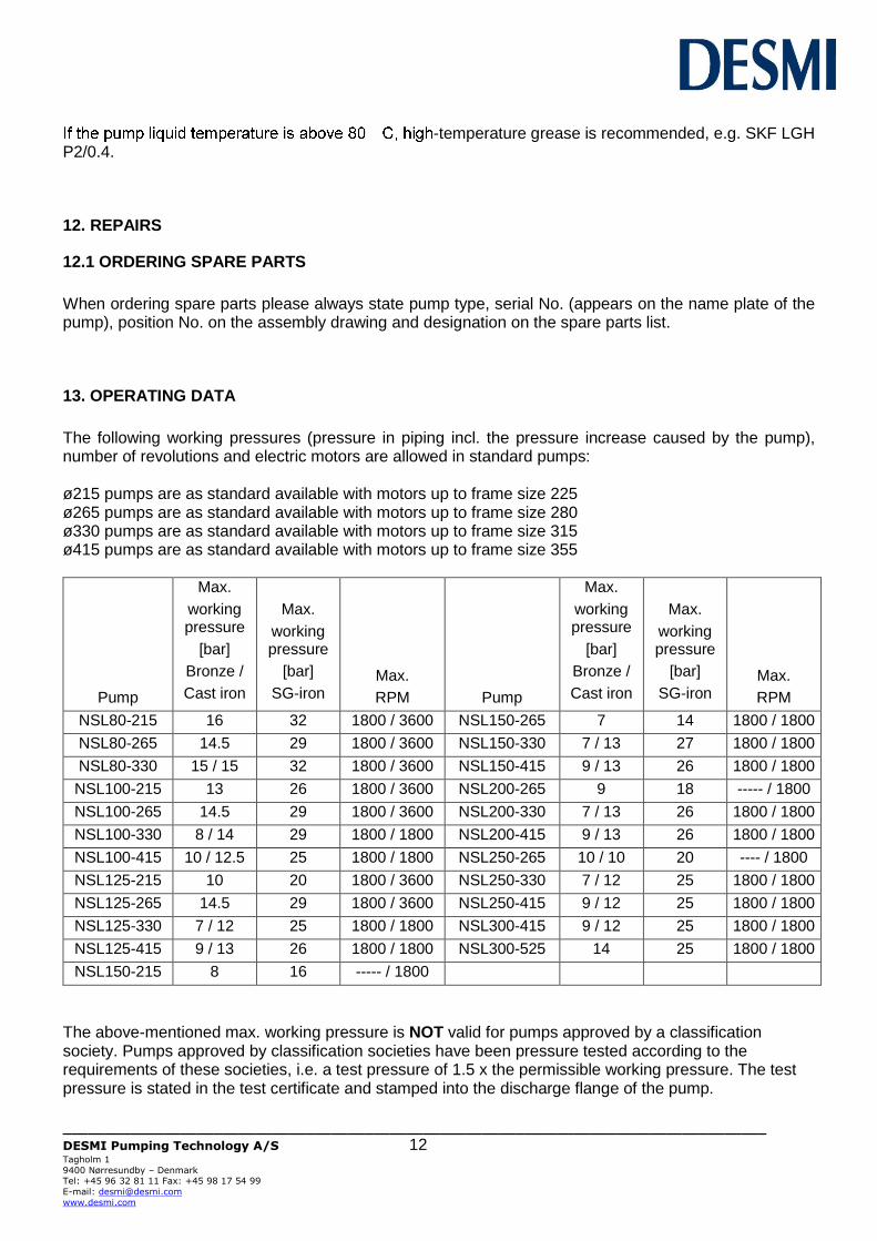
13. OPERATING DATA
The following working pressures (pressure in piping incl. the pressure increase caused by the pump), number of revolutions and electric motors are allowed in standard pumps: ø215 pumps are as standard available with motors up to frame size 225 ø265 pumps are as standard available with motors up to frame size 280 ø330 pumps are as standard available with motors up to frame size 315 ø415 pumps are as standard available with motors up to frame size 355
Pump
Max.
working pressure
[bar]
Bronze /
Cast iron
Max.
working pressure
[bar]
SG-iron
Max.
RPM
Pump
Max.
working pressure
[bar]
Bronze /
Cast iron
Max.
working pressure
[bar]
SG-iron
Max.
RPM
NSL80-215 16 32 1800 / 3600 NSL150-265 7 14 1800 / 1800
NSL80-265 14.5 29 1800 / 3600 NSL150-330 7 / 13 27 1800 / 1800
NSL80-330 15 / 15 32 1800 / 3600 NSL150-415 9 / 13 26 1800 / 1800
NSL100-215 13 26 1800 / 3600 NSL200-265 9 18 ----- / 1800
NSL100-265 14.5 29 1800 / 3600 NSL200-330 7 / 13 26 1800 / 1800
NSL100-330 8 / 14 29 1800 / 1800 NSL200-415 9 / 13 26 1800 / 1800
NSL100-415 10 / 12.5 25 1800 / 1800 NSL250-265 10 / 10 20 ---- / 1800
NSL125-215 10 20 1800 / 3600 NSL250-330 7 / 12 25 1800 / 1800
NSL125-265 14.5 29 1800 / 3600 NSL250-415 9 / 12 25 1800 / 1800
NSL125-330 7 / 12 25 1800 / 1800 NSL300-415 9 / 12 25 1800 / 1800
NSL125-415 9 / 13 26 1800 / 1800 NSL300-525 14 25 1800 / 1800
NSL150-215 8 16 ----- / 1800
The above-mentioned max. working pressure is NOT valid for pumps approved by a classification society. Pumps approved by classification societies have been pressure tested according to the requirements of these societies, i.e. a test pressure of 1.5 x the permissible working pressure. The test pressure is stated in the test certificate and stamped into the discharge flange of the pump.
____________________________________________________________________________________
DESMI Pumping Technology A/S 13 Tagholm 1
9400 Nørresundby – Denmark Tel: +45 96 32 81 11 Fax: +45 98 17 54 99
E-mail: [email protected]
www.desmi.com
14. EU DECLARATION OF CONFORMITY
DESMI PUMPING TECHNOLOGY A/S, hereby declare that our pumps of the type NSL Compact Spacer are manufactured in conformity with the following essential safety and health requirements in the COUNCIL DIRECTIVE 2006/42/EC on machines, Annex 1. The following harmonized standards have been used:
EN/ISO 13857:2008 Safety of machinery. Safety distances to prevent danger zones being reached by the upper limbs
EN 809:1998 + A1:2009 Pumps and pump units for liquids – Common safety requirements
EN12162:2001+A1:2009 Liquid pumps – Safety requirements – Procedure for hydrostatic testing
EN 60204-1:2006/A1:2009 Safety of machinery – Electrical equipment of machines (item 4, General requirements)
Ecodesign Directive (2009/125/EC). Water pumps: Commission Regulation No 547/2012. Applies only to water pumps marked with the minimum efficiency index MEI. See pump nameplate.
Pumps delivered by us connected with prime movers are CE-marked and comply with the above requirements. Pumps delivered by us without prime movers (as partly completed machinery) must only be used when the prime mover and the connection between prime mover and pump comply with the above requirements. Nørresundby, March 05 2019
Henrik Mørkholt Sørensen Managing Director DESMI Pumping Technology A/S Tagholm 1 9400 Nørresundby

____________________________________________________________________________________
DESMI Pumping Technology A/S 14 Tagholm 1
9400 Nørresundby – Denmark Tel: +45 96 32 81 11 Fax: +45 98 17 54 99
E-mail: [email protected]
www.desmi.com
15. ASSEMBLY DRAWING ø215/265
16. SPARE PARTS LIST ø215/265
See ø330/415 pump on the next pages 1 Pump casing
2 Pipe plug 3 Pipe plug 4 Sealing ring 5 Impeller 6 Nut 7 Spring collar 8 Washer 9 Sunk key 10 Shaft seal 11 Water deflector 12 Ring lock 13 Ball bearing 14 Support disc 15 Bearing cover 16 Sunk key 17 Shaft 18 Shaft seal cover 19 Allen screw 21 O-ring 22 Allen screw 36 Pointed screw 58 Copper pipe 59 Hexagon nipple 60 Set screw 63 Motor bracket 64 Set screw 65 Intermediate flange *) 66 Allen screw *) 67 Set screw 69 Guard 70 Coupling part pump 71 Coupling part motor 72 Spacer 73 Pointed screw 74 Coupling discs 76 Allen screw 77 Allen screw 78 Washer 79 Pinch nut 80 Allen screw 81 Sealing washer 86 Pointed screw 93 Set screw 94 Base plate 95 Lock washer 96 Pressure gauge 97 Nipple 98 Sleeve 106 Pressure gauge cock 107 Pipe plug *) Only if motor is bigger than motor bracket
____________________________________________________________________________________
DESMI Pumping Technology A/S 15 Tagholm 1
9400 Nørresundby – Denmark Tel: +45 96 32 81 11 Fax: +45 98 17 54 99
E-mail: [email protected]
www.desmi.com
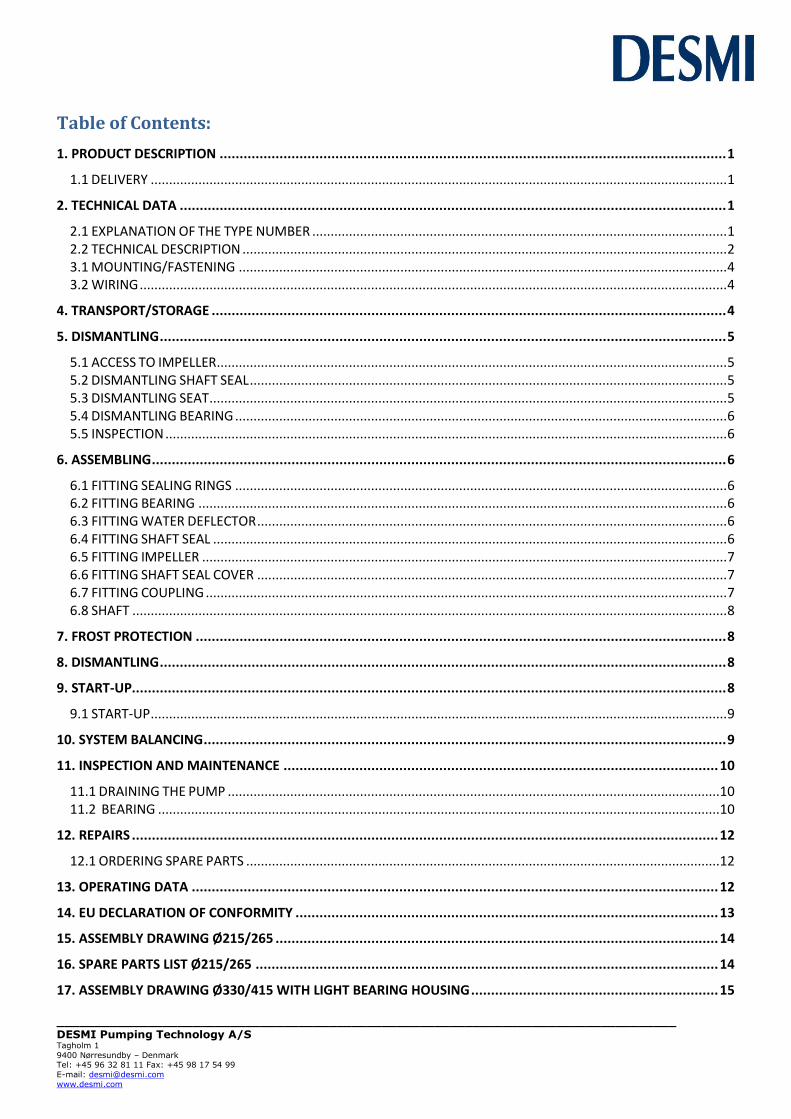
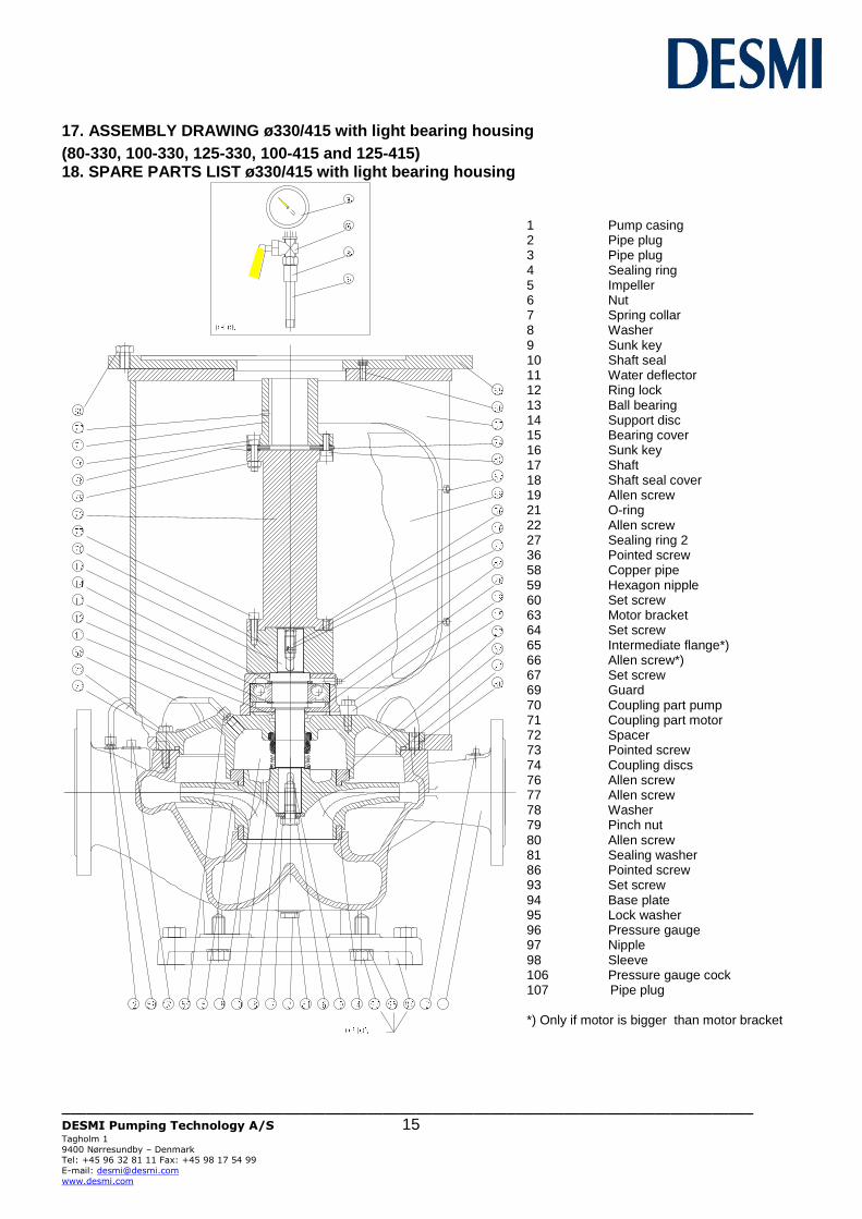
17. ASSEMBLY DRAWING ø330/415 with light bearing housing
(80-330, 100-330, 125-330, 100-415 and 125-415) 18. SPARE PARTS LIST ø330/415 with light bearing housing
1 Pump casing 2 Pipe plug 3 Pipe plug 4 Sealing ring 5 Impeller 6 Nut 7 Spring collar 8 Washer 9 Sunk key 10 Shaft seal 11 Water deflector 12 Ring lock 13 Ball bearing 14 Support disc 15 Bearing cover 16 Sunk key 17 Shaft 18 Shaft seal cover 19 Allen screw 21 O-ring 22 Allen screw 27 Sealing ring 2 36 Pointed screw 58 Copper pipe 59 Hexagon nipple 60 Set screw 63 Motor bracket 64 Set screw 65 Intermediate flange*) 66 Allen screw*) 67 Set screw 69 Guard 70 Coupling part pump 71 Coupling part motor 72 Spacer 73 Pointed screw 74 Coupling discs 76 Allen screw 77 Allen screw 78 Washer 79 Pinch nut 80 Allen screw 81 Sealing washer 86 Pointed screw 93 Set screw 94 Base plate 95 Lock washer 96 Pressure gauge 97 Nipple 98 Sleeve 106 Pressure gauge cock 107 Pipe plug *) Only if motor is bigger than motor bracket
____________________________________________________________________________________
DESMI Pumping Technology A/S 16 Tagholm 1
9400 Nørresundby – Denmark Tel: +45 96 32 81 11 Fax: +45 98 17 54 99
E-mail: [email protected]
www.desmi.com
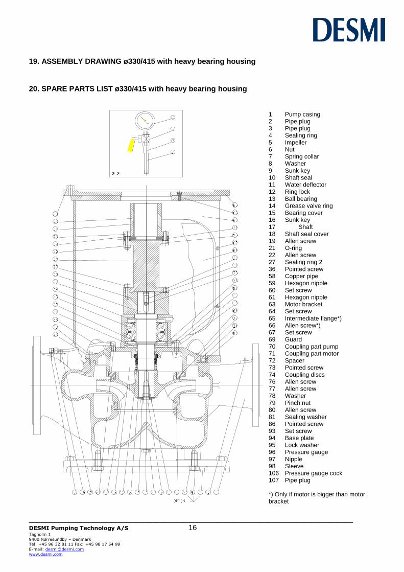
19. ASSEMBLY DRAWING ø330/415 with heavy bearing housing
20. SPARE PARTS LIST ø330/415 with heavy bearing housing
1 Pump casing 2 Pipe plug 3 Pipe plug 4 Sealing ring 5 Impeller 6 Nut 7 Spring collar 8 Washer 9 Sunk key 10 Shaft seal 11 Water deflector 12 Ring lock 13 Ball bearing 14 Grease valve ring 15 Bearing cover 16 Sunk key 17 Shaft 18 Shaft seal cover 19 Allen screw 21 O-ring 22 Allen screw 27 Sealing ring 2 36 Pointed screw 58 Copper pipe 59 Hexagon nipple 60 Set screw 61 Hexagon nipple 63 Motor bracket 64 Set screw 65 Intermediate flange*) 66 Allen screw*) 67 Set screw 69 Guard 70 Coupling part pump 71 Coupling part motor 72 Spacer 73 Pointed screw 74 Coupling discs 76 Allen screw 77 Allen screw 78 Washer 79 Pinch nut 80 Allen screw 81 Sealing washer 86 Pointed screw 93 Set screw 94 Base plate 95 Lock washer 96 Pressure gauge 97 Nipple 98 Sleeve 106 Pressure gauge cock 107 Pipe plug *) Only if motor is bigger than motor bracket
____________________________________________________________________________________
DESMI Pumping Technology A/S 17 Tagholm 1
9400 Nørresundby – Denmark Tel: +45 96 32 81 11 Fax: +45 98 17 54 99
E-mail: [email protected]
www.desmi.com
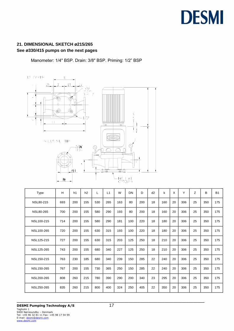
21. DIMENSIONAL SKETCH ø215/265
See ø330/415 pumps on the next pages Manometer: 1/4" BSP. Drain: 3/8" BSP. Priming: 1/2” BSP
Type
H
h1
h2
L
L1
W
DN
D
d2
k
X
Y
Z
B
B1
NSL80-215
693
200
155
530
265
163
80
200
18
160
20
306
25
350
175
NSL80-265
700
200
155
580
290
193
80
200
18
160
20
306
25
350
175
NSL100-215
714
200
155
580
290
181
100
220
18
180
20
306
25
350
175
NSL100-265
720
200
155
630
315
193
100
220
18
180
20
306
25
350
175
NSL125-215
727
200
155
630
315
203
125
250
18
210
20
306
25
350
175
NSL125-265
743
200
155
680
340
227
125
250
18
210
20
306
25
350
175
NSL150-215
763
230
185
680
340
239
150
285
22
240
20
306
25
350
175
NSL150-265
767
200
155
730
365
250
150
285
22
240
20
306
25
350
175
NSL200-265
808
260
215
780
390
290
200
340
23
295
20
306
25
350
175
NSL250-265
835
260
215
800
400
324
250
405
22
350
20
306
25
350
175
____________________________________________________________________________________
DESMI Pumping Technology A/S 18 Tagholm 1
9400 Nørresundby – Denmark Tel: +45 96 32 81 11 Fax: +45 98 17 54 99
E-mail: [email protected]
www.desmi.com
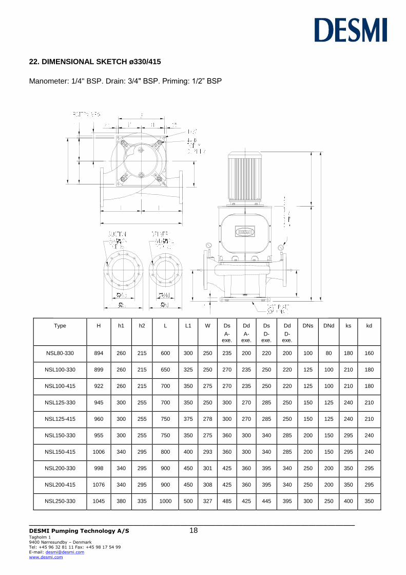
22. DIMENSIONAL SKETCH ø330/415
Manometer: 1/4" BSP. Drain: 3/4" BSP. Priming: 1/2” BSP
Type
H
h1
h2
L
L1
W
Ds
A-exe.
Dd
A-exe.
Ds
D-exe.
Dd
D-exe.
DNs
DNd
ks
kd
NSL80-330
894
260
215
600
300
250
235
200
220
200
100
80
180
160
NSL100-330
899
260
215
650
325
250
270
235
250
220
125
100
210
180
NSL100-415
922
260
215
700
350
275
270
235
250
220
125
100
210
180
NSL125-330
945
300
255
700
350
250
300
270
285
250
150
125
240
210
NSL125-415
960
300
255
750
375
278
300
270
285
250
150
125
240
210
NSL150-330
955
300
255
750
350
275
360
300
340
285
200
150
295
240
NSL150-415
1006
340
295
800
400
293
360
300
340
285
200
150
295
240
NSL200-330
998
340
295
900
450
301
425
360
395
340
250
200
350
295
NSL200-415
1076
340
295
900
450
308
425
360
395
340
250
200
350
295
NSL250-330
1045
380
335
1000
500
327
485
425
445
395
300
250
400
350
____________________________________________________________________________________
DESMI Pumping Technology A/S 19 Tagholm 1
9400 Nørresundby – Denmark Tel: +45 96 32 81 11 Fax: +45 98 17 54 99
E-mail: [email protected]
www.desmi.com
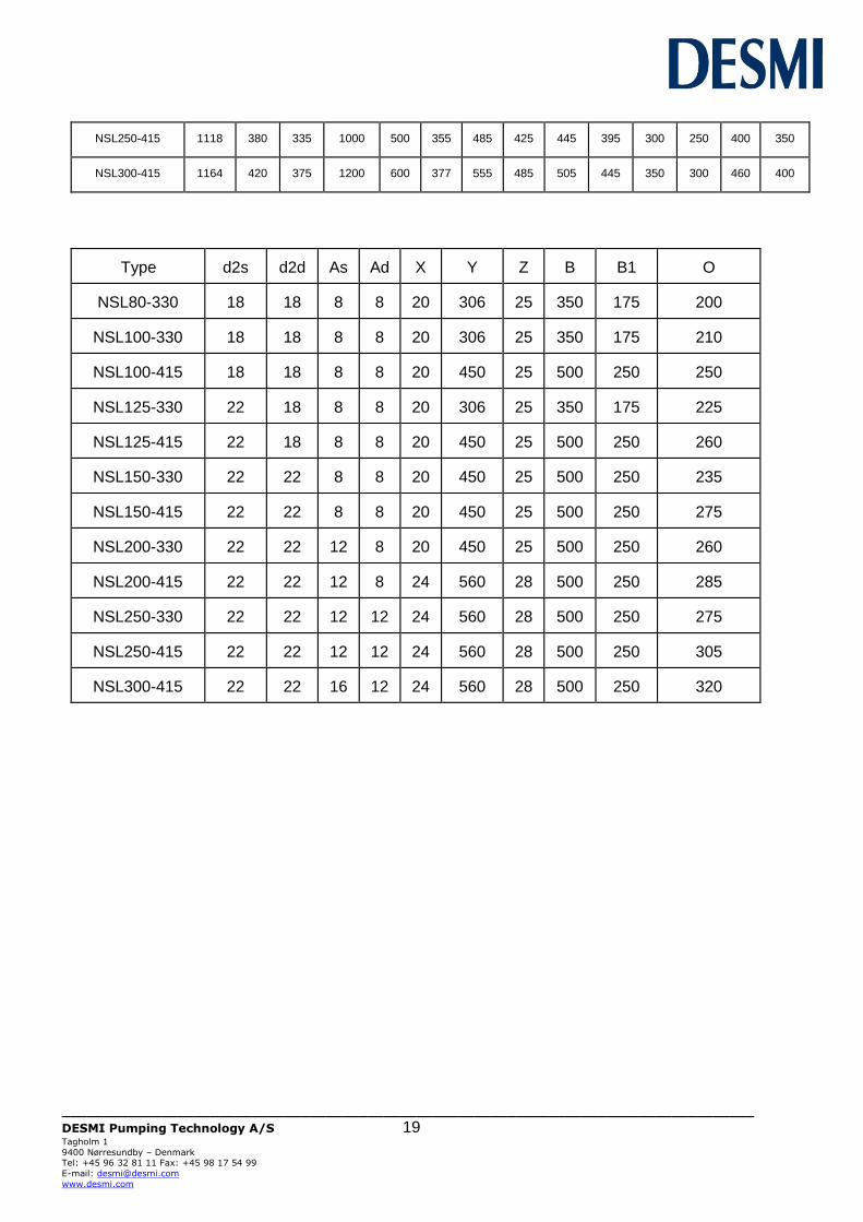
NSL250-415
1118
380
335
1000
500
355
485
425
445
395
300
250
400
350
NSL300-415
1164
420
375
1200
600
377
555
485
505
445
350
300
460
400
Type
d2s d2d
As
Ad
X
Y
Z
B
B1
O
NSL80-330
18
18
8
8
20
306
25
350
175
200
NSL100-330
18
18
8
8
20
306
25
350
175
210
NSL100-415
18
18
8
8
20
450
25
500
250
250
NSL125-330
22
18
8
8
20
306
25
350
175
225
NSL125-415
22
18
8
8
20
450
25
500
250
260
NSL150-330
22
22
8
8
20
450
25
500
250
235
NSL150-415
22
22
8
8
20
450
25
500
250
275
NSL200-330
22
22
12
8
20
450
25
500
250
260
NSL200-415
22
22
12
8
24
560
28
500
250
285
NSL250-330
22
22
12
12
24
560
28
500
250
275
NSL250-415
22
22
12
12
24
560
28
500
250
305
NSL300-415
22
22
16
12
24
560
28
500
250
320