Embed Size (px)
Citation preview
1
PPRROOMMEEXX SSNNCC
OPERATION AND MAINTENANCE
HANDBOOK
INDUSTRIAL HEAD BURNERS WITH
VARIABLE FLAME REGISTER
Heavy oil
EB…NQ
Before the opening of the burner, please read this book familiar, if not all of the requests and sales company, and the failure to prevent the occurrence of danger.The use of non-original accessories will be a serious risk of accident; at the same time, you will give up free services and quality assurance.
2
1) Overview
2) Installation
3) Power Fuel
4) Control cabinet
5) Electrical connection
6) Pipeline
7) The high-pressure system setting
8) Proportional adjustment settings / oil burner
9) Operational guidance
10) Oil burners work flow chart
11) Burner troubleshooting
12) Burner maintenance
13) Safety Guides
Warning!Do not touch the complex regulator lever and lever. When the burner is running, other objects do not close it.
3
1) Overview
1.1 Common language in this book Before the installation, usage and maintenance of the burner, you shall read the instructions, for
the specific instructions, we shall adhere to. Where in the book appears in the following three types of identification are identified very
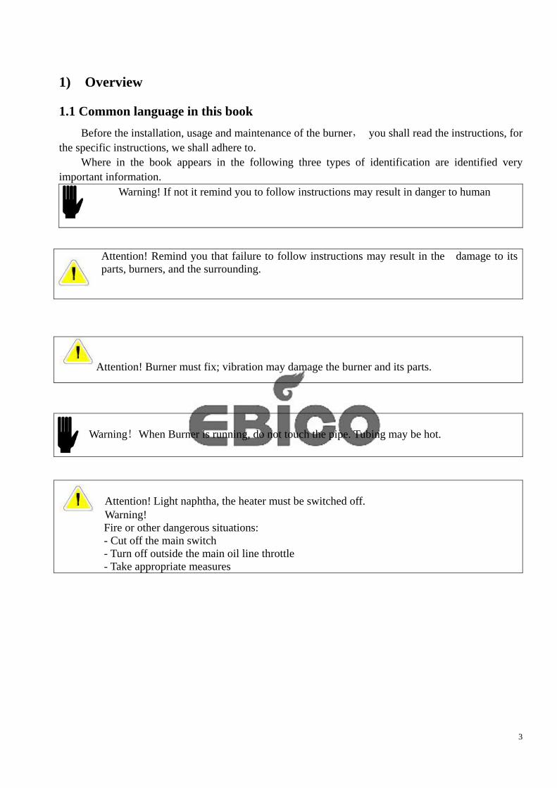
important information. Warning! If not it remind you to follow instructions may result in danger to human
Attention! Remind you that failure to follow instructions may result in the damage to its parts, burners, and the surrounding.
Attention! Burner must fix; vibration may damage the burner and its parts.
Warning!When Burner is running, do not touch the pipe. Tubing may be hot.
Attention! Light naphtha, the heater must be switched off. Warning! Fire or other dangerous situations: - Cut off the main switch - Turn off outside the main oil line throttle - Take appropriate measures
4
1.2 Introduction EB…NQ series is automatic adjustable heavy oil burner, Manufacture using advanced Italian
technology to refine it, all kinds of residue can be internal combustion, enjoying a good reputation by domestic and foreign customers. Features:
Touch-screen control eliminates the need for too many buttons, reducing points of failure. Advanced PLC intelligent control, temperature control accuracy. Failure within the control module, display a variety of failures.
Burner flame operations and monitoring control carry out automatically. Air and fuel ratio regulator servo motor and complex regulation and control according to load
requirements. As it being shutdown, the oil gun automatic purge, to prevent the solidification of heavy oil in the
gun in next turn. Equipped with low noise fan.
Burner can also burn light oil, its viscosity is 4-12mm2 / S (+20 pm)℃
Attention! Combustion of light oil, the pre-heater must be closed。
Introduction!Pressure supply the oil burner must be a 1-3 bar, nozzle pressure of 2-8 bar. Atomizing media pressure 7bar.
Check the following items before the first start: Connect correctly (motor turn right) valve open for tubing tank filled with oil (oil temperature to meet the requirements) boiler room ventilation adequate burner fuel supply Cheong Road, adequate oil pressure and temperature (viscosity see oil
report) Warning: proper installation, adjustment and maintenance of standard is a reliable guarantee to the operation of the burner. When the burner running, ambient temperature 0 ... ... +40 .℃ Explanation!The installation and maintenance of burner fuel line be sure to in accordance with
correct specifications and requirements.
5
When ordering spare parts, please provide the burner plate, pointed out that the following information burner models serial number
Technical parameters Model Kg/h kW
EB1NQ 15-75 170-850 EB2NQ 30-150 340-1670 EB3NQ 50-250 560-2800 EB4NQ 70-350 780-3900 EB5NQ 110-550 1220-6100 EB6NQ 170-850 1900-9500 EB7NQ 200-1000 2250-11160 EB8NQ 300-1400 3150-15630 EB9NQ 360-1800 4000-20000 EB10NQ 440-2200 4900-24500
Conversion standard: light oil fuel: 1Kg / h is equivalent to 11.86KW.
Heavy oil fuel: 1Kg / h is equivalent to 11.22KW The use of gas ignition (LPG) gas pressure required is 300-500mbar, gas consumption is 8m3 / h,
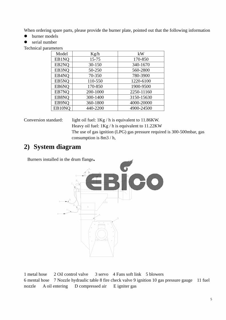
2) System diagram
Burners installed in the drum flange.
1 metal hose 2 Oil control valve 3 servo 4 Fans soft link 5 blowers 6 mental hose 7 Nozzle hydraulic table 8 fire check valve 9 ignition 10 gas pressure gauge 11 fuel nozzle A oil entering D compressed air E igniter gas
6
3) Power, fuel Check all combustion equipment voltage and frequency of parts (including motors, heaters, electric valves, servo, coil, control cabinet), the control cabinet should be installed short-circuit and overload protection agencies. Control Voltage: 230V, 50HZ, 1-PHASE, the main voltage: 400V, 50Hz ,3-PHASE. If the voltage fluctuations, power supply must be installed. Power supply anti-interference device must be installed, as there is interference. Burner for heavy oil fuels, its viscosity is the largest 1450mm2 / S (CST) (+50 ℃ pm). Burner fuel (heavy oil) Before entering the pump, to filter, filter mesh is generally 80-100 mesh atomized oil temperature must be set to allow access to the spray nozzle to achieve the best combustion conditions, oil pump allows oil group's warm-up to atomization temperature. An electronic controller controls oil temperature. See Appendix oil Burner can also burn light oil, its viscosity is 4-12mm2 / S (+20 ℃ pm)
Must confirm the self-pressure (through the tank supply) or the pressure pump (see setup) supply to the burner group, so the oil tanks shall beyond the burner pump inlet, pipeline road get heated through the heat area, steam heating or hot oil. The viscosity of the oil cannot be higher than the minimum oil we provide international standards with international standards, disable non-standard oil (corrosive, volatile, toxic, etc.) oil requirements in Annex 1.
Heavy oil filters require the installation of heating device.
4) Control cabinet Control cabinet must install away from heat. Surrounding temperature must be below 45 .℃ Prevent the control cabinet from the violent vibration (if any vibration, damping device shall use). The most important thing is to connect the control cabinet and the appliance with ground.
5) Electric Connection Systems must be in accordance with national standards and made by insulated wire. To avoid overheating, must choose the appropriate diameter; auxiliary circuit with a minimum diameter 1.5mm2.
Note: The temperature sensor cable, flame sensor cable must use shielded cable. Electronic wire to the burner, such as high temperature region, you must use heat- resistance wire.
Wire section, please refer to the electronic control line schematic

7
6) Pipeline Refer to our installation diagram, heavy oil and steam pipes must separate from each other. To convenience the facilitate maintenance and replacement of equipment, connect the system to attachment (such as filters, pumps, electrical) must be able to buy the finished product, install globe valve at a reasonable place.
7) Hydraulic system settings Check whether all the globe valves open or close correctly, the entire motors move is correct before the operation. If there is pressure pump, first, discharge of the air, after opening, adjusts the oil pressure to 3 kg; Then open the high-pressure oil pump, manually open the valve to clean the air properly. After pump filled with oil, then adjust high-pressure pump and pressure pump pressure.
Note: If the heater is not full of oil, do not charge, or it will be damage the heater. Aviod to start oil pump when oil do not reach the pump. Check the suitable space between all couplings and accessories,then the power is turned on heating (to regulate the temperature of the fuel, light viscosity / temperature chart). Reach target temperature, re-check the gapwithin the pressure and the coupling.
8) Proportional adjustment settings / oil burner 8.1 EB…NQ is a industrial heavy oil fuel burner. Its operation, start and stop are fully automatic. Burner automatic function can fulfill in an automated system. Burner adjustment 1:5 Burner devices equipped with group of a valve so that can supply oil to the burner and atomize medium. When in delivery, burner control has been included. Burner components: 1. Oil gun 2. Point firearms 3. Compound regulator + gear 4. Flame Detector 5. Combustion air control plate 6. Observation hole
8
8.1.1 Oil Gun Gun made up of the steel pipes installed in their internal composition. Oil, atomize medium enter into the nozzle through the tube. Atomizing media is import within the tube; the oil has imported within the area between the tube and center. Oil gun equipped with oil pressure gauge, oil pressure within 2-8bar. Atomization medium and fuel enter into the burner through the valve as the required.
8.1.2 Point firearms
Point of guns is a gas ignition. Junction box and the ignition transformer installed in the control cabinet. Combustion chamber is where gas and air mixture. Point guns at the point guns flame front ignited the gas nozzle. Point of the main components of firearms
nozzle tube Connect Cable gas nozzle ignition electrode
When the mixture of pre-combustion gas and air in the nozzle is being ignited by electrode ignition, the combustion happens!
Warning: ignition voltage of 8000V
Liquefied gas and combustion air supplied by pipeline through the valve device entry point guns according to the amount necessary.
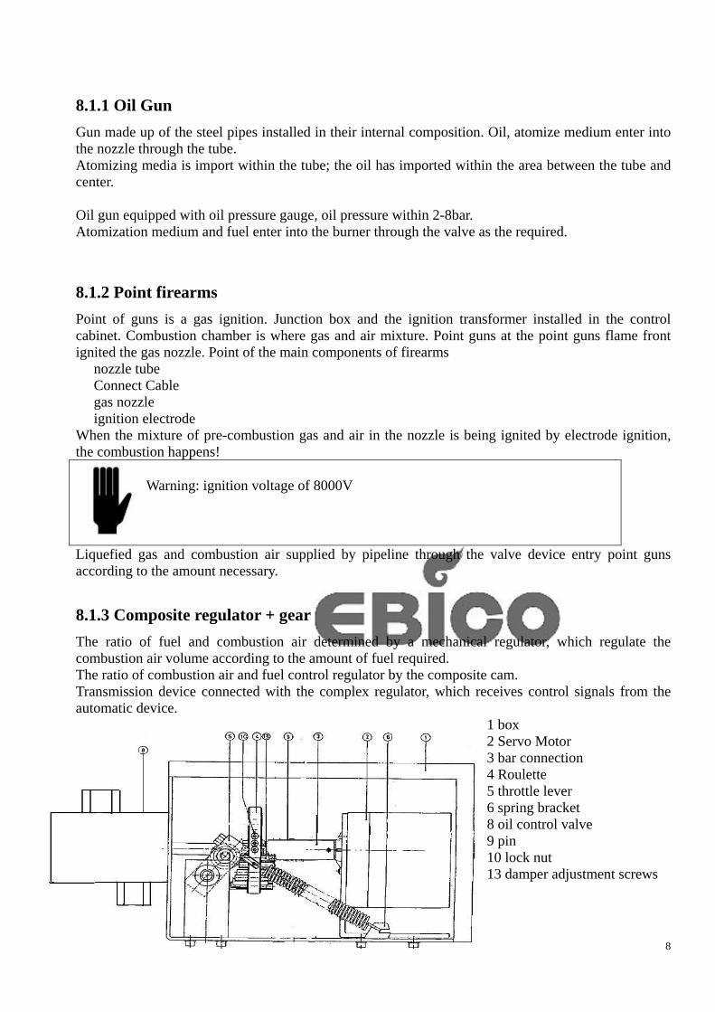
8.1.3 Composite regulator + gear
The ratio of fuel and combustion air determined by a mechanical regulator, which regulate the combustion air volume according to the amount of fuel required. The ratio of combustion air and fuel control regulator by the composite cam. Transmission device connected with the complex regulator, which receives control signals from the automatic device.
1 box 2 Servo Motor 3 bar connection 4 Roulette 5 throttle lever 6 spring bracket 8 oil control valve 9 pin 10 lock nut 13 damper adjustment screws

9
8.1.4 Servo Motors explanation
Cam switch (limit switch) in the factory test set as follows: I = full load (approximately 130 °) II = burner off (about 0 °) III = ignition load (about. 30 °) IV = standby V = standby V II = partial load (about 40 °) A = Regulator (in under cover) B = release lever C = the factory regulation, prohibit the release switch! D = scale only indicates servo motor shaft rotation angle. Chart shows the basic position of the cam disk. Release lever B, camshaft can be torn off. This will enable the cam manually
Warning! Do not release the switch C.pan changes the location of cam disk will damage servo motor and may change the burner settings

10
8.1.5 Fire detection devices
The main flame detector monitors the main burner flame. Flame detector connecting pipe installed in the burner, It comes with a cooling air connection. Cooling air to keep the flame detector can be clean and to prevent overheating.
air connector
8.1.6 Observation hole Observe the flame and burning state through the observation hole. It can be removed to wash ash as through a long time.
11
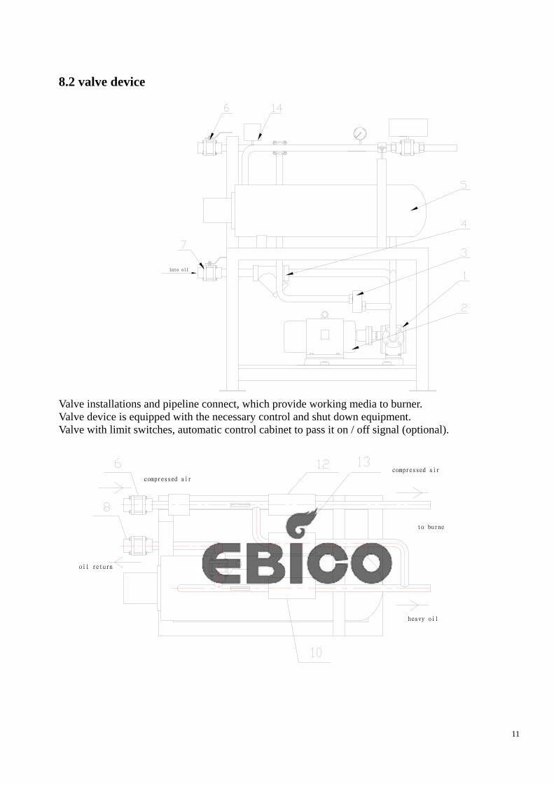
8.2 valve device
into oil
Valve installations and pipeline connect, which provide working media to burner. Valve device is equipped with the necessary control and shut down equipment. Valve with limit switches, automatic control cabinet to pass it on / off signal (optional).
compressed air
heavy oil
compressed air
oil return

12
1.pump 2.motor 3 Hydraulic Control Valve 4 oil filter 5 Electric Heaters 6 into the compressed air valve 7 into the oil ball valve 8 return oil ball valve 9 hydraulic manual adjustment valve 10 into the oil and gas dynamic valve 1 12 atomizer medium pneumatic valve 13 purge valve 14 atomizer medium pressure switch
8.3.1 Fuel pressure regulator
1 - Valve
2 - Adjusting screw support bolts
3 - Adjustment screw plug
4 - Adjustment screw
5 - Spring center plug-in
6 - Spring
7 - Bored Piston
8 - Thimble
9 - Thimble support bolt
10 - Pressure gauge connection plug
13
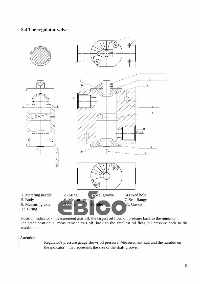
8.4 The regulator valve
1. Metering needle 2.O-ring 3.Seal groove 4.Fixed hole 5. Body 6. Measure groove 7. Seal flange 8. Measuring axis 9.outlet 10.Inlet 11. Gasket 12. 0-ring Position Indicator -: measurement axis off, the largest oil flow, oil pressure back to the minimum. Indicator position +: measurement axis off, back to the smallest oil flow, oil pressure back to the maximum.
Attention! Regulator's pressure gauge shows oil pressure. Measurement axis and the number on the indicator that represents the size of the shaft groove。
14
9) Operational guidance
9.1 preparations for the first time start / before start - After installation, clean pipe with compressed air. - Burner and valve settings in the working conditions (installation, connection, etc.). - Emergency stop circuit is ready. - After installation, check the piping and equipment - Inlet pipeline is full of oil. - System lock loop, testing is completed and is in working condition. - Pipeline safety equipment has been tested and is in working condition.
9.2 Start
9.2.1 Fans
Start the fan; observe the fan’s shift, watch fans turn clockwise from the motor side
9.2.2 Pump
check whether the pump oil road is open before the start. Manual shut-off valves open, inlet pipeline is full of oil. Pressure control valve is open, the outlet pipeline in the valve closed. Establish a stable pressure within the pipeline after starting of the pump immediately. Check Pipeline seal. Starting pressure control valve, attention to how the pressure control achieved. Pressure keeps stabilized, the oil into the burner, when the valve is open.
9.2.2 Gas Ignition
Gas valve opens, the pressure transferred to 0.5bar. Start blower; press the ignition button manually on the touch screen to observe whether the flame formed there, if not check the gas pressure, ignition electrodes, and ignition transformer.
9.2.2 Burner
Before the start of the burner, check whether the oil burner, atomization medium, gas and combustion air supply pipe is open. Inlet l and gas valves must be in the "off" position,
9.3 Stop and emergency stop
9.3.1 Stop
Before the burner stops, shall switch to manual control to the minimum load, in order to prevent excessive boiler temperature fluctuations.
15
9.3.2 Emergency Stop
In the cases of emergency, Press the emergency stop button, turn off the burner immediately, after the dissolution of the situation and the restart of burner is allowed.
9.4 running normally
During normal operation, shall check the operator regularly as the following: - Whether the device noise is normal or not. - Fan running sounds normal, no vibration, bearing temperature is not too high. - Valve, damper and its implementing agencies in working condition. - Valve, throttle in the correct working position. - Cable (no risk of damage). - Piping and other equipment in good working condition.
16
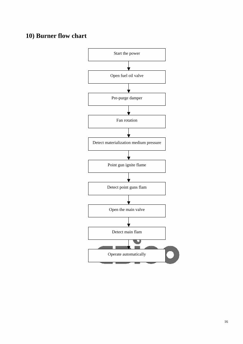
10) Burner flow chart
Start the power
Pre-purge damper
Open fuel oil valve
Fan rotation
Detect materialization medium pressure
Point gun ignite flame
Detect point guns flam
Open the main valve
Detect main flam
Operate automatically
17
11) Trouble shooting
11.1 Overview Burning is usually close by the pressure of safe devices fault, such as flame detectors, heavy oil temperature is low switch, caused by atomization switch. During burner operation period, the fixed value always changes. So always keep an accurate pressure value. Original value and change the value to be record in the operating record.
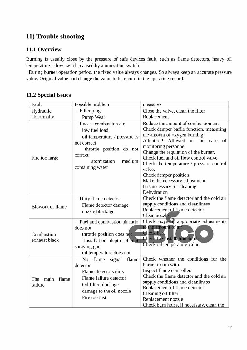
11.2 Special issues
Fault Possible problem measures Hydraulic abnormally
·Filter plug Pump Wear
Close the valve, clean the filter Replacement
Fire too large
·Excess combustion air low fuel load oil temperature / pressure is not correct throttle position do not correct atomization medium containing water
Reduce the amount of combustion air. Check damper baffle function, measuring the amount of oxygen burning. Attention! Allowed in the case of monitoring personnel Change the regulation of the burner. Check fuel and oil flow control valve. Check the temperature / pressure control valve. Check damper position Make the necessary adjustment It is necessary for cleaning. Dehydration
Blowout of flame ·Dirty flame detector Flame detector damage nozzle blockage
Check the flame detector and the cold air supply conditions and cleanliness Replacement of flame detector Clean nozzle
Combustion exhaust black
·Fuel and combustion air ratio does not throttle position does not Installation depth of not spraying gun oil temperature does not
Check oxygen, appropriate adjustments to the amount of air Check here Check the installation depth Check oil temperature value
The main flame failure
· No flame signal flame detector Flame detectors dirty Flame failure detector Oil filter blockage damage to the oil nozzle Fire too fast
Check whether the conditions for the burner to run with. Inspect flame controller. Check the flame detector and the cold air supply conditions and cleanliness Replacement of flame detector Cleaning oil filter Replacement nozzle Check burn holes, if necessary, clean the
18
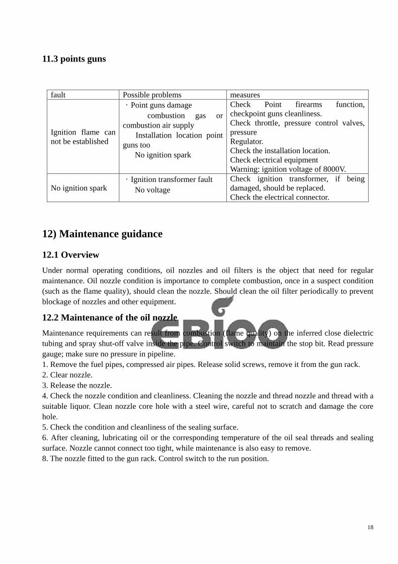
11.3 points guns
fault Possible problems measures
Ignition flame can not be established
·Point guns damage combustion gas or combustion air supply Installation location point guns too No ignition spark
Check Point firearms function, checkpoint guns cleanliness. Check throttle, pressure control valves, pressure Regulator. Check the installation location. Check electrical equipment Warning: ignition voltage of 8000V.
No ignition spark ·Ignition transformer fault No voltage
Check ignition transformer, if being damaged, should be replaced. Check the electrical connector.
12) Maintenance guidance
12.1 Overview Under normal operating conditions, oil nozzles and oil filters is the object that need for regular maintenance. Oil nozzle condition is importance to complete combustion, once in a suspect condition (such as the flame quality), should clean the nozzle. Should clean the oil filter periodically to prevent blockage of nozzles and other equipment.
12.2 Maintenance of the oil nozzle
Maintenance requirements can result from combustion (flame quality) on the inferred close dielectric tubing and spray shut-off valve inside the pipe. Control switch to maintain the stop bit. Read pressure gauge; make sure no pressure in pipeline. 1. Remove the fuel pipes, compressed air pipes. Release solid screws, remove it from the gun rack. 2. Clear nozzle. 3. Release the nozzle. 4. Check the nozzle condition and cleanliness. Cleaning the nozzle and thread nozzle and thread with a suitable liquor. Clean nozzle core hole with a steel wire, careful not to scratch and damage the core hole. 5. Check the condition and cleanliness of the sealing surface. 6. After cleaning, lubricating oil or the corresponding temperature of the oil seal threads and sealing surface. Nozzle cannot connect too tight, while maintenance is also easy to remove. 8. The nozzle fitted to the gun rack. Control switch to the run position.
19
12.3 points guns
Before start to maintenance, first check whether point guns gas valve and blower should turned off, point guns should be no voltage.
Warning: ignition voltage of 8000V
Normal operation, point guns do not need any maintenance. So loosen the cover above the burner, remove the high-voltage wire, trachea out the point guns from the burner with a socket spanner. The distance within electrode and Front point guns firing is 2-3mm. If the cable reach the point rifle shell or the distance is too large, adjust immediately, otherwise it will damage the ignition transformer. Attention! Point guns recommended settings: - After the LPG pressure regulator is about 0.3-0.5 bar
12.4 Heater
Oil heater temperature exceeds the set temperature, or the heater and the pump output pressure, output pressure varied widely, indicating the phenomenon of electric heater with a plug, flange should remove from the heating rods, cleaning the filter. 13) Safety Guides
13.1 Overview
This security guide describes the period of normal operation and maintenance, how to prevent damage to personnel and equipment. Ignition vain several times due to equipment failure and other reasons, drying tube, lift, bag full of oil, non-ignition! Must be on white material, run a certain time to suck the oil, or prone to explosion.
13.2 Heater
Before starting, the heater that not full of oil should not open to prevent dry-burned heater and damage to the heater. Pump to the heater should oil manually.
13.3 Normal operation
During normal operation, the operator should pay attention to status and function of the burner regularly. Faulty equipment and piping leaks must repair. Attention! Before repairing, inform the control room.
13.4 Repair and maintenance
Normal operation, make the guidance to maintenance of each device. Specify increase in maintenance projects in the stop period, monitoring personnel should give detailed guidance to special projects.
20
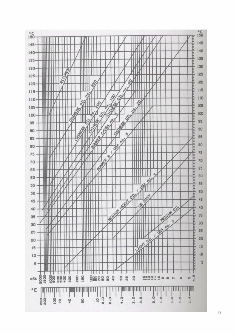
The increase of maintenance projects of the device should be notice to all staff. Eye-catching bulletin boards and futures should be a written notice, to prevent misconduct and danger caused by human error. Before the maintenance of electrical equipment, we should switch or remove fuses, break it with circuit. The device should be marked with the date and tags. Before the pipeline maintenance, check the pipe should be no pressure and the valve should be closed. Remove the valve hand wheel or lock with chain. The valve operated by the motor should break up with circuit. All valves should provide notations. Maintenance of gas pipeline should use safety gear. Temporary demolition work platform, rails, etc., should be marked with warning signs to prevent falls and accidents. Use lifting equipment, work does not have to crawl or reach out enough. During maintenance period, all temporary arrangement should return to the original condition, inform other workers the work has concluded. Annex 1 Some common sense of heavy oil usage Heavy oil is crude oil extracted gasoline, diesel heavy residual oil, which is characterized by high molecular weight, high viscosity. The proportion of heavy oil is generally 0.82 to 0.95, in the 10,000 ~ 11,000 kcal / kg or so. The composition is mainly carbon hydrates, with part of another (about 0.1 ~ 4%) of sulfur and traces of inorganic compounds 1. Variety features It also known as heavy fuel oil, residual oil, the dark brown fuel viscous liquid, medium viscosity, fuel performance, heat large. Use for boiler fuel, good for atomization, full of fuel, coke and ash less corrosive. Higher flash point, safe for storage and usage. Fuel oil is refined out of crude oil in oil, widely used in ship boiler fuel, heating fuel, metallurgical furnaces and other industrial furnace fuels. Mainly by cracking fuel oil residue from oil and oil made from straight-run residues, which is characterized by high viscosity, containing non-hydrocarbon compounds, resin and asphalting and more. The main technical indicators of fuel oil viscosity, sulfur content, flash point, water, ash, and mechanical impurities. 1、Viscosity: Viscosity is the most important performance index of fuel oil, fuel oil level is the main basis for classification. It is a measure of liquidity resistance capability, its size, said fuel oil fluidity, easy to pump and ease of atomization performance is good or bad. More commonly used domestic and 40 ℃ Viscosity (distillate type fuel oil) and 100 ℃ Viscosity (residual type fuel oil). Fuel oil in China in the past the industry standard with a viscosity (80 ℃, 100 ℃) as a quality control index, kinematic viscosity at 80 ℃ divided by grade. Oil kinematic viscosity is the oil dynamic viscosity and density ratios. Kinematic viscosity of the units is Stokes, That Stokes, called Sri Lanka. When the fluid dynamic viscosity as a park, when the density of 1g/cm3 dynamic viscosity of 1 stokes. CST is an abbreviation Centistokes means determined here, that a one per cent of Stokes.
21
2、 the sulfur content. The sulfur content of fuel oil can cause excessive corrosion of metal equipment and environmental pollution. According to the level of sulfur content, can be classified as high sulfur fuel oil, sulfur and low sulfur fuel oil. 3、 flash point. Involving the use of safety indicators, flash point is too low which will bring fire hazards. 4、water. The presence of moisture will affect the fuel's freezing point, with increasing water content, pour point fuel oil increased gradually. In addition, the water will also affect the combustion properties of fuel oil machinery, may cause the furnace flame, shutdown accident. 5、ash. Ash remaining after burning the part cannot be burned, especially catalytic cracking cycle oil and slurry oil mixed with fuel oil, the Si-Al catalyst powder makes pumps, valves and accelerated wear. In addition, the ash will be covered in the boiler-heating surface, so heat transfer of deterioration. 6、mechanical impurities. Mechanical impurities clog the filter, causing pump wear and fuel injector plug, affecting the normal combustion. Second, the classification of fuel oil Fuel oil as the oil refining process in the final variety, quality control has a strong specificity. The formation of the final fuel products are crude oil varieties, processing techniques, processing depth, and many other factors. According to different standards, fuel oil can look Category: 1、according to whether the formation of the factory goods, fuel and fuel oil can be divided into goods for personal use fuel oil. Fuel means goods of goods shipped form part of the fuel; own fuel for refineries that produce raw materials or fuel without the formation of commodity sectors in the factory fuel oil. 2、according to the machining process, fuel oil, heavy oil can be divided into pressure, decompression of heavy oil, heavy oil catalytic heavy oil and mix. Atmospheric pressure of heavy oil that refineries out of heavy oil distillation unit; decompression means heavy oil refinery vacuum distillation unit out of heavy oil; catalytic heavy oil that refineries, fractionation of the heavy oil cracking unit (known as slurry); mixed heavy oil generally that decompression of heavy oil and heavy oil catalytic mixture. 3、according to use fuel oil can be divided into marine fuel oil and furnace fuel oil (heavy oil) and other fuel oil. Third, the current domestic situation 1、 recent years, domestic oil prices get higher. Lots of heavy oil in the market do not meet national standards, with excessive moisture, excessive moisture can affect the success rate of ignition, combustion caused outages also the quality of the fire phenomenon, take a bit of heavy oil on the newspaper, burning with a lighter point, if the water would be to burn more or issued Zizi's voice. Then heavy oil is good for dehydration. 2、the so-called the "burn oil" is a coal tar, chemical oil, blended oil, a pungent smell unpleasant, serious corrosion. The burners on the seal, oil pump, nozzle, oil gun, air valve, heater with serious injuries. Reduce life circle greatly. Therefore, it shall prohibit. 3、the usage of heavy oil and light oil can not have chemical reaction, because in 3 minutes before the end of combustion with a light oil purging channel, to prevent the solidification of heavy oil in the pipeline, the impact of the second use. If the heavy oil and light oil in the chemical reaction of heavy oil pipelines cannot be wash out, and even blocked pipe. We can put a little light oil and heavy oil in a plastic disposable cups, stirring gently with a tool which. If there is something very sticky, like produce, cannot use this light oil. Should be change for other things a kind of light oil; if the light oil to heavy oil completely dissolved, and just the light oil can be used.
22