Embed Size (px)
Citation preview
OPERATION AND INSTALLATION MANUAL
TANK-TYPE WATER HEATERS FOR HORIZONTAL MOUNTING
OKCEV 100 OKCV 125 OKCEV 125 OKCV 160 OKCEV 160 OKCV 180 OKCEV 180 OKCV 200 OKCEV 200
Družstevní závody Dražice - strojírna s.r.o. Dražice 69, 294 71 Benátky nad Jizerou tel.: +420 / 326 370 990 fax: +420 / 326 370 980 e-mail: [email protected]

- 2 -
CONTENT
1 TECHNICAL SPECIFICATION OF PRODUCT ................................................................................................. 4
1.1 ADVICE FOR CUSTOMERS .................................................................................................................. 4
1.1.1 HOT WATER CONSUMPTION ..................................................................................................... 4
1.1.2 ENERGY SAVING ......................................................................................................................... 5
1.1.3 EMERGENCY POWER CONSUMPTION ....................................................................................... 5
1.2 CONSTRUCTION AND GENERAL HEATER DIMENSION ....................................................................... 5
2 OPERATION AND FITTING INSTRUCTIONS ............................................................................................... 10
2.1 OPERATING CONDITIONS ................................................................................................................ 10
2.2 WALL MOUNTING ............................................................................................................................ 10
2.3 PLUMBING FIXTURE ......................................................................................................................... 11
2.4 ELECTRIC INSTALLATION .................................................................................................................. 13
2.5 CONNECTION OF INDIRECT HEATER TO HOT WATER HEATING SYSTEM ........................................ 14
2.6 PUTTING THE HEATER INTO OPERATION ........................................................................................ 15
2.7 PUTTING OUT OF SERVICE, DISCHARGE .......................................................................................... 15
2.8 INSPECTION, MAINTENANCE & CARE FOR THE APPLIANCE ............................................................ 16
2.9 MOST FREQUENT FUNCTION FAILURES AND THEIR CAUSES .......................................................... 17
3 OPERATION OF THERMOSTAT ................................................................................................................. 18
3.1 SERVICING ........................................................................................................................................ 18
3.1.1 OPERATING DEVICES OF THE HEATER ..................................................................................... 18
3.1.2 TEMPERATURE SETTING .......................................................................................................... 18
4 IMPORTANT NOTICES .............................................................................................................................. 19
4.1 INSTALLATION REGULATIONS.......................................................................................................... 19
4.2 PRODUCT ACCESSORIES AND SPARE PARTS .................................................................................... 19
4.3 DISPOSAL OF PACKAGING MATERIAL AND NON-FUNCTIONING PRODUCT.................................... 20

- 3 -
Meaning of pictograms used in Manual
Important information for heater users.
Recommendations of manufacturer, observance of which will ensure trouble-free operation and long service life of the product.
CAUTION!
Important notice to be observed.
READ CAREFULLY THE BELOW INSTRUCTIONS PRIOR TO THE INSTALLATION OF THE HEATER!
Dear Customer,
The Works Cooperative of Dražice - Machine Plant, Ltd., would like to thank you for your decision to use a product of our brand. With this guide, we will introduce you to the use, construction, maintenance and other information on electrical water heaters.
The manufacturer reserves the right for engineering modification of the product. The product is designed for permanent contact with drinkable water.
It is recommended to use the product in indoor environment with air temperatures from +2°C to 45°C and a relative humidity up to 80%.
Product’s reliability and safety is proven by tests implemented by the Engineering Test Institute in Brno.

- 4 -
1 TECHNICAL SPECIFICATION OF PRODUCT The heater is designed for accumulation heating of service water using electricity or thermal energy via an exchanger (for the combined design only). Water is heated by an electric element (or a heat exchanger) in an enamelled thermally insulated accumulator at the time defined by the power supplier. The element is at the time of heating controlled by a thermostat the temperature of which can be adjusted continuously (within the range between 5°C and 74°C). Once the selected temperature is reached, heating interrupts automatically. Water accumulated in the heater is then used for consumption. The heater keeps constant pressure of water from the water main. If the combination faucet hot water valve is opened, water from the water supply conduit pressed out by cold water pressure flows out of the heater. Hot water flows out through the top part, and water flowing in remains in the bottom part of the heater. Pressure principle allows hot water withdrawal at any place from the heater (Figure 7, Figure 8).
Operating activity:
a) Water heating by electric energy After the heater is connected to electric network, the heating element starts heating water. The element is turned on and off by a thermostat. After reaching the temperature set, the thermostat switches off the electric circuit and discontinues water heating. The control light signals if the element is in operation (light is on) or if it is off (the light goes out). In case of longer operation without using the heated volume, the thermostat has to be set to position 5°C to 8°C (set the “snowflake” symbol on the thermostat selector) to avoid its freezing, or electricity supply to the heater has to be switched off. In combined versions, the stop valve on the inlet to the exchanger has to be closed, which prevents heating water in the hot water heating system.
b) Service water heating via thermal energy through heat exchanger
Closing valves of the heat exchanger must be opened which ensures heating water flow from the hot water heating system. Together with a closing valve, it is recommended to install an air outlet valve at the inlet to the heat exchanger in order to bleed the heat exchanger as needed, in particular before the beginning of the heating season. The time of heating using the heat exchanger depends on the temperature and flow of water in the hot water heating system. A combined heater is made in universal design - depending on the need of connecting the closing valves to the heating element either from the right, or from the left.
1.1 ADVICE FOR CUSTOMERS
1.1.1 HOT WATER CONSUMPTION
Consumption of hot water in households depends on the number of people, amount of sanitary equipment, length, diameter and insulation of piping in the flat, or on individual habits of users. The cheapest option of water heating comes at the time when the electricity rate is reduced.

- 5 -
Find out in what time intervals your electricity supplier provides reduced tariff and, depending on that information, select relevant volume and power input of the heater so that your hot water consumption covered the needs of your household.
1.1.2 ENERGY SAVING
Hot utility water reservoir is insulated by means of a top-quality polyurethane foam with zero CFCs content. Adjust the temperature of the heater's thermostat to that level only that you need to run your home. Thus you will reduce electricity consumption, as well as the amount of lime sediments on the walls of the receptacle and on the electric element's pit.
1.1.3 EMERGENCY POWER CONSUMPTION
If no heated water is taken from the heater, a small amount of heat leaks. This loss is measured for a period of 24 hours at the temperature of 65°C in the heater, and at 20°C in its ambient area. The resulting value is expressed in kWh/24h and indicates the amount of power needed to maintain the set temperature (Table 1).
HEATER TYPES NOMINAL
CAPACITY (l) TIME OF CONTENT HEATING (hours)
ELECTRICITY CONSUMPTION FOR HEATING OF THE
CONTENTS FROM 15oC TO 65oC (kWh)
OKCEV 100 100 3 6
OKCV 125; OKCEV 125 125 3,8 7,5
OKCV 160; OKCEV 160 152 5 9,5
OKCV 180; OKCEV 180 180 5 10,
OKCV 200; OKCEV 200 200 5,5 12
Table 1
1.2 CONSTRUCTION AND GENERAL HEATER DIMENSION
The heater vessel is made of a steel plate and tested by 0.9 MPa overpressure. The heat exchanger is tested with a pressure of 0.6 MPa. The inside of the receptacle is enamelled. A flange is welded onto the bottom of the vessel with a flange lid screwed to it. A sealing ring is inserted between the flange lid and the flange. Thermowells for placing a heating element and sensors of regulation thermostat and safety fuse are located in the flange lid. Anode rod is mounted on M8 nut. The water reservoir is insulated by means of

- 6 -
polyurethane foam. Electric wiring is placed underneath the plastic removable cover. The temperature of water can be set using the thermostat. In combined versions, a heat exchanger is welded in the pressure vessel. The heat exchanger is only intended for the heating circuit.
Heaters dimensions - Figure 1, Figure 2, Table 3, Table 4
TYPE
- OKCV 125 OKCV 160 OKCV 180 OKCV 200
OKCEV 100
OKCEV 125
OKCEV 160
OKCEV 180
OKCEV 200
CAPACITY l 100 125 152 180 200
MAX OPERATING OVERPRESSURE IN THE HEATER
MPa 0,6
MAX OPERATING OVERPRESSURE IN THE EXCHANGER*
MPa - 0,4
ELECTRIC CONNECTION V 1 PE-N 230 V/50Hz
POWER INPUT W 2000 2200
IP PROTECTION
IP 44
MAX TEMPERATURE OF HSW °C 80
RECOMMENDED HSW TEMPERATURE °C 60
HEIGHT OF THE HEATER mm - 881
1050 1052
1235 1237 1187 1287
DIAMETER OF THE HEATER mm - 524 524 524 584 584
MAX WEIGHT OF THE HEATER WITHOUT WATER kg 41 59/47 68/56 80/69 84/73
TIME OF HEATING WITH ELECTRICITY FROM 10°C TO 60°C
hrs 3 3,8 5 5 5,5
LOAD PROFILE W M L L XL XL
DAILY ELECTRICITY CONSUMPTION kWh 6,54 11,98 12,43 19,21 19,88
MIXED WATER V40 l 164,98 195,75 244,59 266,52 301,93
* The OKCEV series heaters do not have a heat exchanger.

- 7 -
TYPE
OKCV 125 OKCV 160 OKCV 180 OKCV 200
EXCHANGER HEAT SURFACE m2 0,7 0,7 0,75 0,75
RATED THERMAL OUTPUT AT HEATING WATER TEMPERATURE OF 80°C AND FLOW 720 l/h
W 16800 16800 18000 18000
TIME OF HEATING BY EXCHANGER FROM 10°C TO 60°C
min 26 35 38 43
RATED THERMAL OUTPUT AT HEATING WATER TEMPERATURE OF 80°C AND FLOW 310 l/h
W 10260 10260 1100 11000
TIME OF HEATING BY EXCHANGER FROM 10°C TO 60°C
min 43 53 63 72
Table 2

- 8 -
OKCEV 100, OKCEV 125, OKCEV 160, OKCEV 180, OKCEV 200
Figure 1
Table 3
TYPE OKCEV 100
OKCEV 125
OKCEV 160
OKCEV 180
OKCEV 200
A 887 1052 1237 1187 1287 B 435 600 750 600 600 C 723 928 1063 897 936 D 524 524 524 584 584 E 190 190 236 258 258 F 226 226 226 246 246 G 230 230 230 252 252 H 556 556 556 618 618
- 9 -
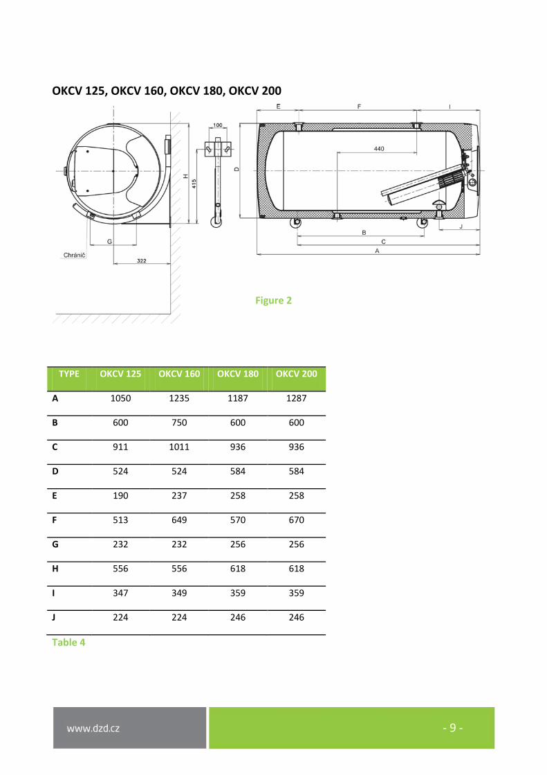
OKCV 125, OKCV 160, OKCV 180, OKCV 200
Figure 2
TYPE OKCV 125 OKCV 160 OKCV 180 OKCV 200
A 1050 1235 1187 1287
B 600 750 600 600
C 911 1011 936 936
D 524 524 584 584
E 190 237 258 258
F 513 649 570 670
G 232 232 256 256
H 556 556 618 618
I 347 349 359 359
J 224 224 246 246
Table 4
- 10 -
2 OPERATION AND FITTING INSTRUCTIONS
2.1 OPERATING CONDITIONS
The heater shall only be used in accordance with the conditions specified on the power plate and in instructions for electric wiring. Besides legally acknowledged national regulations and standards, also conditions for connection defined in local electric and water works have to be adhered to, as well as the installation and operation manual. The temperature at the place of heater installation must be higher than +2°C; and the room must not freeze. The appliance has to be mounted at a convenient place; it means that the appliance must be easily available for potential necessary maintenance, repair or replacement, as the case may be.
We would like to emphasise that the heater must not be connected to power supply if work involving flammable liquids (petrol, spot remover) or gases, etc., is performed nearby.
If water is strongly calcareous we recommend that any of the common decalcifying devices was installed with the appliance, or that the thermostat was set to the minimum operating temperature of 60oC (setting to position „60“).For proper operation, drinkable water of adequate quality shall be used. To avoid potential sediments we recommend that the device was installed together with a water filter.
2.2 WALL MOUNTING
Prior to mounting, check the loading capacity of the wall and, depending on the type of masonry, choose a suitable anchorage material, or reinforce the wall, if needed. Mount the water heater only in horizontal position so that, from the front view, the right edge of the heater was placed at least 600 mm from the opposite wall. In combined and electric heaters, elbows have to be attached to the hot service water inlet and outlet prior to their suspension in brackets right under the ceiling and, by turning these elbows, mounting left has to be determined - either from the right, or from the left. With regard to various types of carrying masonry and broad assortment of special anchorage material available at the market, we do not provide heaters with this material. The anchorage system has to be selected individually, depending on the conditions (). We recommend an authorised company perform mounting on the wall and anchorage, or discuss the anchorage with professional.
If the hot water heater is mounted in a tight, small space, or in an intermediate ceiling, etc., you have to make sure that the connecting side of the appliance (connections to water supply, area for electric plugging) remained accessible and no heat accumulation occurs. Free space of up to 600 mm from the bottom edge of the heater has to be available under the heater.

- 11 -
Fitting of hinges and indicator onto the heater - the hinges can be purchased as accessories
Figure 3
2.3 PLUMBING FIXTURE
For potential disconnection of the heater, the service water inlets and outlets must be provided with screw coupling Js 3/4“.The safety valve is mounted on the cold water inlet identified with a blue ring.
Each hot service water pressure heater must have a safety valve with a membrane loaded by a spring. Nominal clearance of safety valves is defined by standard. Heaters are not equipped with a safety valve. The safety valve must be easily accessible, as close to the heater as possible. The inlet pipes must have at least the same clearance as the safety valve. The safety valve is placed high enough to secure dripping water drain by gravity. We recommend mounting the safety valve onto a branch pipe. This allows easier exchange without having to drain the water from the heater. Safety valves with fixed pressure settings from the manufacturer are used for the assembly. Starting pressure of a safety valve must be identical to the maximum allowed heater pressure and at least 20 % higher than the maximum pressure in the water main (Table 5). If the water main pressure exceeds such value, a reduction valve must be added to the system. No stop valves can be put between the heater and the safety valve. During the assembly, follow the guide provided by the safety equipment manufacturer.

- 12 -
It is necessary to check the safety valve each time before putting it into operation. It is checked by manual moving of the membrane from the seat, turning the make-and-break device button always in the direction of the arrow. After being turned, the button must click back into a notch. Proper function of the make-and-break device results in water draining through the safety valve outlet pipe. In common operation, such a check needs to be implemented at least once a month, and after each heater shutdown for more than 5 days. Water may be dripping off the drain pipe of the safety valve; the pipe must be open into the air, pointed down; environment temperatures must not drop below zero. When draining the heater, use the recommended drain valve. First, close the water supply into the heater. For proper safety valve operation, a backflow valve must be mounted on the inlets pipes, preventing spontaneous heater draining and hot water penetrating back into the water main.
Please find necessary pressure values in the below Table 5. We recommend that the hot water distribution from the heater was as short as possible to minimise heat losses.
Table 5
Heaters must be provided with a discharge valve mounted on the cold service water inlet to the heater for potential disassembly or repair.
OKCV 125, OKCV 160, OKCV 180 OKCV 200
Figure 4
SAFETY VALVE STARTING PRESSURE (MPa)
ADMISSIBLE OPERATING WATER HEATER OVERPRESSURE
(MPa)
MAX PRESSURE IN COLD WATER PIPES (MPa)
0,6 0,6 up to 0,48
0,7 0,7 up to 0,56
1 1 up to 0,8
O - Air outlet valve U - Shut-off valve P1 - Safety valve with backflow flap P2 - Safety valve for heating circuit M - Manometr Z - Test valve V - Drain valve

- 13 -
OKCEV 100, OKCEV 125, OKCEV 160, OKCEV 180, OKCEV 200
Figure 5
2.4 ELECTRIC INSTALLATION
• The electric wiring scheme is attached to the water heater on the side of the electric installation guard (Figure 6).
• Connection, repairs and wiring inspections may only be implemented by a company (person) authorised to such activity.
• The heater is connected to the 230 V/50 Hz electrical network using a fixed moving conductor with a switch that turns off all network poles and the circuit breaker (protector).
• The degree of protection of electric parts of the heater is IP 44.
Figure 6
U - Shut-off valve P - Safety valve with backflow flap M - Manometr Z - Test valve V - Drain valve

- 14 -
2.5 CONNECTION OF INDIRECT HEATER TO HOT WATER HEATING SYSTEM
It is recommended to install stop valves on the heating water inlet and outlet (for possible dismantling of the heater). The valves have to be as close to the heater as possible to avoid higher thermal losses (Figure 7 a Figure 8).
Figure 7
Figure 8

- 15 -
2.6 PUTTING THE HEATER INTO OPERATION
After connecting a heater to the water main, the hot water heating system, the electric network, and after testing its safety valve (based on the valve manual attached), the heater may be put into operation. Before opening the power supply, the heater must be filled with water. The process of first heating must be executed by licensed professional who has to check it. Both the hot water outlet pipe and safety armature parts may be hot.
During the heating process the pressurised connection water that increases its volume due to heating must drip off the safety valve. In non-pressurised connection water drips off the overflow combination faucet. When heating is finished, the set temperature and the actual temperature of consumed water should be roughly equal. After connecting the heater to the water main and electrical power system, and after checking the safety valve (following the instructions attached to the valve), the heater can be put into operation.
Procedure:
1. Check both water and electric installation; for combined heaters, check the installation to a hot water heating system. Check proper placement of operating and safety thermostat sensors. The sensors must be inserted all the way in; first the operating and then the safety thermostat.
2. Open the hot water valve on the combination faucet. 3. Open the cold water inlet valve to the heater. 4. As soon as the water starts running through the hot water valve, the heater is filled and the valve
closes. 5. In case of a leakage (flange lid), we recommend fastening the flange lid bolts. 6. Fasten the electric installation cover. 7. In case of service water heating by electric energy, turn on the electricity (for combined heaters,
the heating water valve at the heating water entry to heating insert must be closed). 8. When heating service water with electric energy from the hot water heating system, turn the
electricity off and open the valves of heating water input and output, possibly de-aerate the exchanger.
9. When commencing operation, flush the heater until the cloudiness in the water is gone. 10. Make sure to fill in properly the warranty certificate.
2.7 PUTTING OUT OF SERVICE, DISCHARGE
If the hot water heater is put out of service for a longer time, or if it is not going to be used it has to be drained and disconnected from the electric supply network on all poles. The switch for the supply lead or the fuse cut-outs have to be shut off.
At places with permanent risk of frost the hot water heater must be drained before the cold season starts if the appliance remains out of service for several days and if the power supply is disconnected.

- 16 -
Drainage of service water shall be performed after closing the shut-off valve in the cold water supply piping (through the discharge valve for safety valve combination), and with simultaneous opening of all hot water valves of connected fittings. Hot water may outflow during the drainage! If there is a risk of frost it has to be considered that not only the water in the hot water heater and in the hot water piping may get frozen but also the water in the entire cold water supply piping. It is therefore advisable to drain all fittings and piping that carry water, up to the part where the house water meter is installed (connection of the house to water main) which is not jeopardised by frost. When the heater is put in service again, it has to be ensured that it is filled with water and the water flowing out at the hot water valves is free of bubbles.
2.8 INSPECTION, MAINTENANCE & CARE FOR THE APPLIANCE
During the heating process the water that increases its volume during the heating must visibly drip off the safety valve outlet (in non-pressurised connection this water drips off the combination faucet valve). In full heating (about 74°C) the volumetric water gain is approx. 3.5 % of the vessel capacity. The function of the safety valve has to be checked regularly. If the safety valve control knob is lifted or turned to the “Control” position, the water must flow out easily, without any obstacles, from the safety valve element to the outfall line. In common operation, such a check needs to be carried out at least once a month, and after each heater shutdown that exceeds 5 days.
Caution! In doing so, the cold water supply pipe and the connection fitting of the heater may get heated! If the hot water heater does not work, or if hot water is not withdrawn, no water shall drip off the safety valve. If water drips, then the water pressure in the supply piping is either too high or the safety valve is defective. Please call a specialised plumber immediately!
If water contains too many minerals, an expert has to come to remove the scale that forms inside the vessel, as well as free sediments. This has to be performed after one or two years of operation. Repetitive water heating causes limestone sediment on both the vessel walls and chiefly the flange lid. The sedimentation depends on the hardness of water heated, its temperature, and amount of hot water consumed.
We recommend checking and cleaning the heater from scale and eventual replacement of the anode rod after two years of operation. The anode life is theoretically calculated for two years of operation; however, it changes with water hardness and chemical composition in the place of use. Based on such an inspection, the next term of anode rod exchange may be determined. Have the company in charge of service affairs clean and exchange the anode.
When draining water from the heater, the combination faucet valve for hot water must be open, preventing occurrence of under-pressure in the heater vessel which would stop water from draining. The cleaning is carried out through the hole in the flange - dismantle the flange lid and clean the vessel. A new sealing has to be used for re-fitting. Since the inside of the heater has special enamel, which must not get in contact with the scale removing agent - do not work with a lime pump. Remove the lime layer with a timber and suck it off, or wipe it off with a clout. After that, the appliance must be rinsed thoroughly and the heating process is checked the same as during the initial putting in operation. Do not use any abrasive

- 17 -
cleaning agents (such as liquid sand, chemicals - acid, alkaline) or dye thinners (such as cellulose thinner, trichlor, and the like) to clean the outer shell of the heater. For cleaning use a wet clout and add a few drops of liquid cleaning agent for household applications.
2.9 MOST FREQUENT FUNCTION FAILURES AND THEIR CAUSES
DEFECT CONTROL LIGHT FAILURE
Water in the heater is cold
• is on • The temperature set on the thermostat is too low
• Heating element failure
Water in the heater is cold
• is not on • No supply voltage
• Thermostat failure
• Safety thermostat shut off probably due to failed operation thermostat
Water is not warm enough
• is on • Failure of one of the coils in the element (contains 2)
Temperature of water is not corresponding to block the setting
• is on • Defective thermostat
Water is constantly dripping off the safety valve
• is not on • Input pressure too high
• Faulty safety valve
Table 6
Do not try to repair the failure yourselves. Seek either expert or service help. It does not take much for an expert to remove the defect. When making a repair appointment, report the type and serial number you find on the performance plate of your water heater.

- 18 -
3 OPERATION OF THERMOSTAT
3.1 SERVICING
3.1.1 OPERATING DEVICES OF THE HEATER Service device of heaters of 100 - 200 l capacity are located under the transparent guard of the control panel.
Thermostat knob Electric circuit closing indicator lamp Tipping plastic guard
Figure9
3.1.2 TEMPERATURE SETTING
Water temperature is set by turning the thermostat knob. The desired symbol is adjusted against the fixed point on the control panel.
Figure10
Lower temperature range (about 5°C)
Fixed point on the control panel
„Anti-freezing“ temperature (about 8°C)
Upper temperature range (about 74°C)
„Ideal“ temperature (about 55°C)

- 19 -
Adjusting the thermostat selector at the left backstop does not mean permanent shutoff of the heating element. When the heater is in use without blocking the daily rate, we do not recommend the temperature to be set above 55°C. The maximum value to select is „ECO“.
4 IMPORTANT NOTICES
4.1 INSTALLATION REGULATIONS
- Without a confirmation of performed electrical installation issued by an authorised company, the warranty certificate shall be void.
- Check and exchange the Mg anode regularly. - You have to apply for approval of a local power supplier to connect the heater. - No stop valves can be put between the heater and the safety valve. - If the overpressure in the water main exceeds 0.48 MPa, a pressure control valve must be mounted
before the safety valve. - All hot water outputs must have a combination faucet. - Before filling the heater with water for the first time, it is recommended to fasten the flange
connection nuts of the heater. - It is not allowed to handle the thermostat, aside from temperature resetting with a control button. - All electric installation handling, adjustment and replacement of the regulation elements shall only
be performed by an authorised service company. - The thermal fuse must not be turned off! In case of thermostat defect, the thermal fuse interrupts
electric power input to the rating element if the water temperature in the heater exceeds 90°C. - As an exception, the thermal fuse may also switch off due to water overheating caused by
overheating the hot water heating system boiler (in case of a combined heater). - We recommend you operate the heater with one type of energy.
Both the electric and water installation must follow and meet the requirements and regulations relevant in the country of use.
4.2 PRODUCT ACCESSORIES AND SPARE PARTS
The product is supplied with a safety valve, thermometer, elements to be used for suspension of the heater on the wall, i.e. brackets (bended stiffened tubes). The above parts are packed and placed in the packaging in the top part of the heater. Also additional fastening elements - hinges can be purchased with the heater. It is a set of two hinges and bolts to fasten them to the heater, and an earthing bolt. The catalogue number of this set is 102000702. It is in your own interest to check the completeness of the accessories.

- 20 -
4.3 DISPOSAL OF PACKAGING MATERIAL AND NON-FUNCTIONING PRODUCT
A service fee for providing return and recovery of packaging material has been paid for the packaging in which the water heater was delivered. The service fee was paid pursuant to Act No. 477/2001 Coll., as amended, at EKO-KOM a.s. The client number of the company is F06020274. Take the water boiler packages to a waste disposal place determined by the town. When the operation terminates, disassemble and transport the discarded and unserviceable heater to a waste recycling centre (collecting yard), or contact the manufacturer.
30-9-2015