Embed Size (px)
Citation preview
E-1625
Operation and Installation Manual
Hydraulic Overspeed Governor
P-8S( )-( )
Issue 3: March 11, 2013
EASA CZ.21G.0011 EASA.21J.072
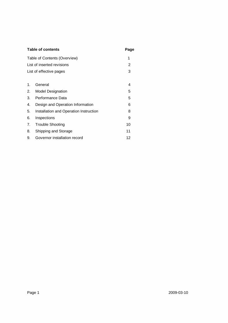
Table of contents Page Table of Contents (Overview) 1
List of inserted revisions 2
List of effective pages 3
1. General 4
2. Model Designation 5
3. Performance Data 5
4. Design and Operation Information 6
5. Installation and Operation Instruction 8
6. Inspections 9
7. Trouble Shooting 10
8. Shipping and Storage 11
9. Governor installation record 12
Page 1 2009-03-10
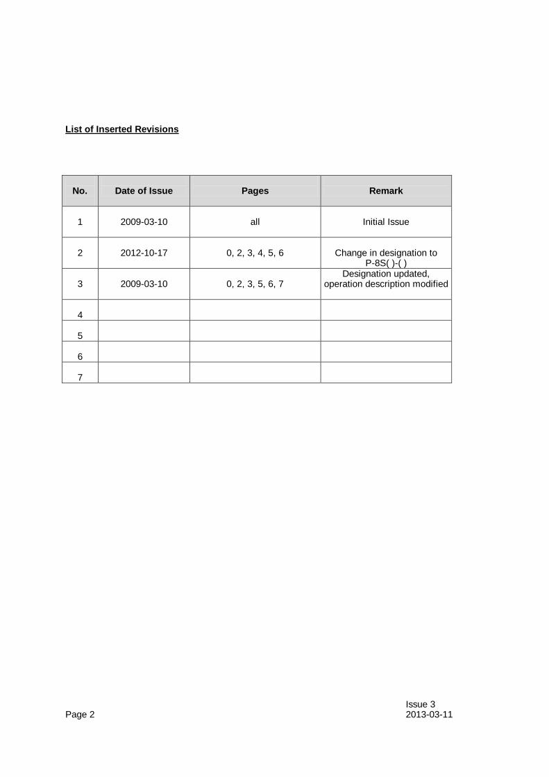
List of Inserted Revisions
No.
Date of Issue
Pages
Remark
1
2009-03-10
all
Initial Issue
2
2012-10-17
0, 2, 3, 4, 5, 6
Change in designation to
P-8S( )-( ) 3
2009-03-10
0, 2, 3, 5, 6, 7
Designation updated, operation description modified
4
5
6
7
Issue 3 Page 2 2013-03-11
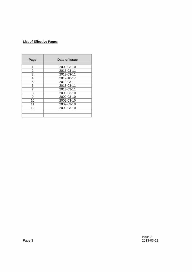
List of Effective Pages
Page
Date of Issue
1 2009-03-10 2 2013-03-11 3 2013-03-11 4 2012-10-17 5 2013-03-11 6 2013-03-11 7 2013-03-11 8 2009-03-10 9 2009-03-10
10 2009-03-10 11 2009-03-10 12 2009-03-10
Issue 3 Page 3 2013-03-11
1.0 GENERAL
The P-8S( )-( ) hydraulic overspeed propeller governors are single acting governors developed for hydraulically variable pitch propellers to protect propellers against overspeeding, produced by AVIA Propeller.
1.0.1 Statement of purpose This publication provides operation, installation and line maintenance information for the
Avia Propeller governors. Installation, removal, operation and trouble shooting data is included in this publication.
However, the airplane manufacturer's manuals and applicable propeller manuals should be used in addition to this information.
1.1 DEFINITION OF COMPONENT LIFE AND SERVICE 1.1.1 Overhaul Overhaul is a periodic process and contains the following items: - disassembly - inspection of parts - reconditioning of parts - reassembly The overhaul interval is based on hours of service (operating time) or on calendar time. At such specified periods, the overspeed governors should be completely disassembled
and inspected for cracks, wear, corrosion and other unusual or abnormal conditions. As specified, certain parts should be refinished, and certain other parts should be replaced.
For overhaul interval for the overspeed governors please refer to Service Bulletin 1. 1.1.2 Repair Repair is correction of minor damage caused during normal operation. It is done on an
irregular basis, as required. 1.1.2.1 A repair does not include an overhaul. 1.1.2.2 Amount, degree and extent of damage determines whether or not a governor can be
repaired without overhaul. 1.1.3 Component Life Component life is expressed in terms of total hours of service (TT, or Total Time) and in
terms of hours of service since overhaul (TSO, or Time Since Overhaul). Both references are necessary in defining the life of the component. Occasionally a part
may be "life limited", which means that it must be replaced after a specified period of use. Overhaul returns the component or assembly to zero hours TSO (Time Since Overhaul),
but not to zero hours TT (Total Time). No life limit is established for the overspeed governors P-8S( )-( ). Page 4 2012-10-17
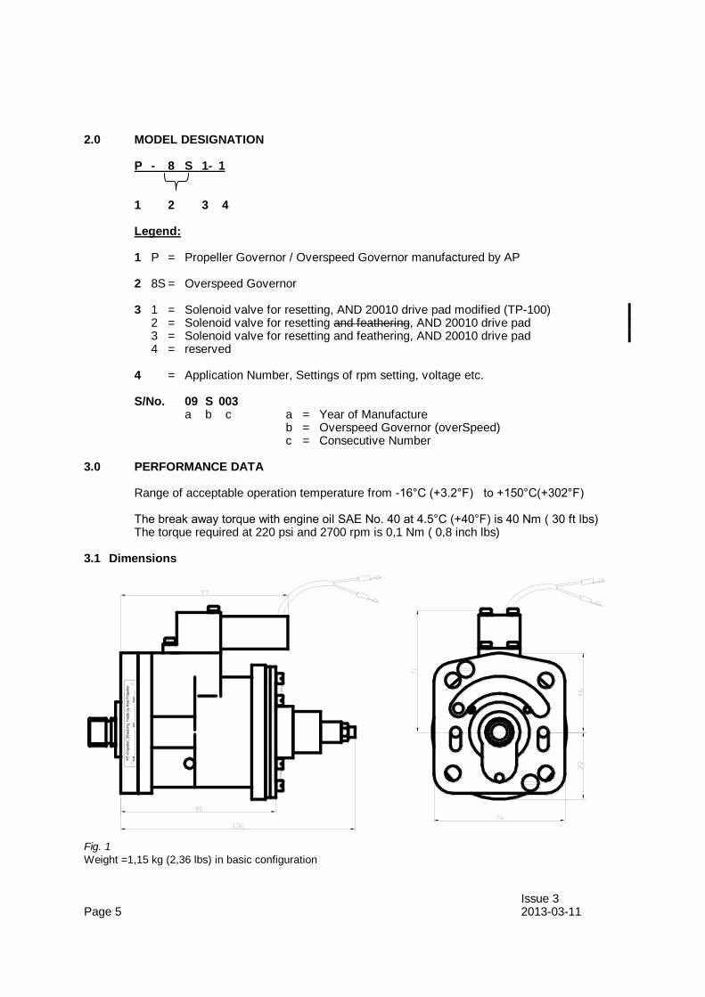
2.0 MODEL DESIGNATION P - 8 S 1- 1 1 2 3 4 Legend: 1 P = Propeller Governor / Overspeed Governor manufactured by AP 2 8S = Overspeed Governor 3 1 = Solenoid valve for resetting, AND 20010 drive pad modified (TP-100) 2 = Solenoid valve for resetting and feathering, AND 20010 drive pad 3 = Solenoid valve for resetting and feathering, AND 20010 drive pad 4 = reserved 4 = Application Number, Settings of rpm setting, voltage etc. S/No. 09 S 003 a b c a = Year of Manufacture b = Overspeed Governor (overSpeed) c = Consecutive Number 3.0 PERFORMANCE DATA Range of acceptable operation temperature from -16°C (+3.2°F) to +150°C(+302°F) The break away torque with engine oil SAE No. 40 at 4.5°C (+40°F) is 40 Nm ( 30 ft lbs) The torque required at 220 psi and 2700 rpm is 0,1 Nm ( 0,8 inch lbs) 3.1 Dimensions
Fig. 1
Weight =1,15 kg (2,36 lbs) in basic configuration
Issue 3 Page 5 2013-03-11
MT-P
ropelle
r, S
traubin
g
made b
y A
via
Pro
pelle
r
P/N
_________________
S/N
____________ A
SSY____
4.0 DESIGN AND OPERATION INFORMATION The Avia Propeller aircraft overspeed governors P-8S( )-( ) are base mounted centrifugal
overspeed governors for use with single acting constant speed propeller control systems on turboprop engines.
The propeller overspeed governor is located on the reduction gearbox. It limits propeller
RPM should the primary propeller governor fail. Constructed in the same manner as the primary governor with speeder spring, flyweight assembly, and pilot valve, and driven by gears from the propeller shaft, the overspeed governor constantly monitors propeller RPM. Should the primary propeller governor fail and the prop begin to overspeed, the overspeed
governor will ACTIVATE at given speed setting by detouring high pressure oil back to the reduction gearbox. The overspeed governor should then govern the propeller at given speed. Ground test of the overspeed governor is provided by a test valve actuated by a
28-VDC solenoid. A pushbutton, located on the TEST panel at the bottom of the instrument panel in the cockpit, activates the solenoid and opens the test valve, allowing high pressure
oil to reset the normal overspeed setting to given percentage below normal. A properly functioning overspeed governor is indicated during ground test by the propeller RPM stabilizing at adjusted lower propeller speed. Releasing the TEST button resets the
overspeed governor to normal operation and the propeller RPM rises toward the normal governing RPM.
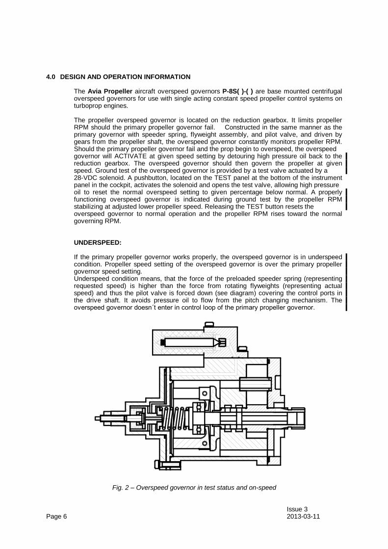
UNDERSPEED: If the primary propeller governor works properly, the overspeed governor is in underspeed
condition. Propeller speed setting of the overspeed governor is over the primary propeller governor speed setting.
Underspeed condition means, that the force of the preloaded speeder spring (representing requested speed) is higher than the force from rotating flyweights (representing actual speed) and thus the pilot valve is forced down (see diagram) covering the control ports in the drive shaft. It avoids pressure oil to flow from the pitch changing mechanism. The overspeed governor doesn´t enter in control loop of the primary propeller governor.
Fig. 2 – Overspeed governor in test status and on-speed Issue 3 Page 6 2013-03-11
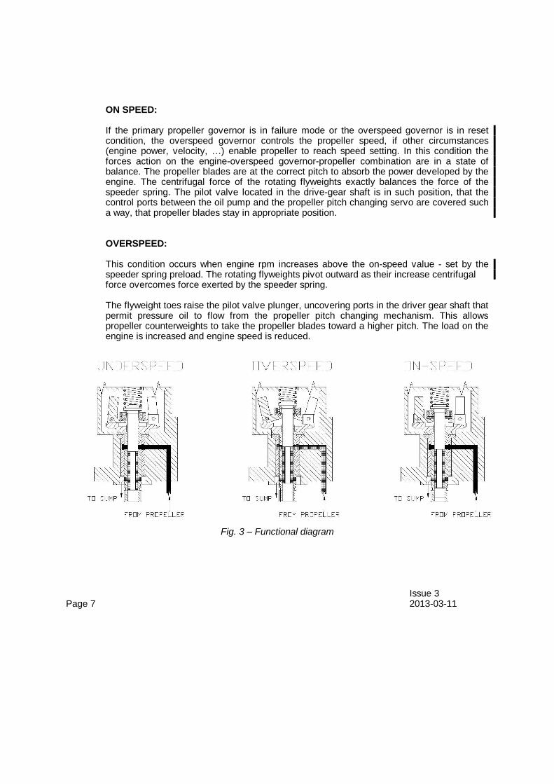
ON SPEED: If the primary propeller governor is in failure mode or the overspeed governor is in reset
condition, the overspeed governor controls the propeller speed, if other circumstances (engine power, velocity, …) enable propeller to reach speed setting. In this condition the forces action on the engine-overspeed governor-propeller combination are in a state of balance. The propeller blades are at the correct pitch to absorb the power developed by the engine. The centrifugal force of the rotating flyweights exactly balances the force of the speeder spring. The pilot valve located in the drive-gear shaft is in such position, that the control ports between the oil pump and the propeller pitch changing servo are covered such a way, that propeller blades stay in appropriate position.
OVERSPEED: This condition occurs when engine rpm increases above the on-speed value - set by the
speeder spring preload. The rotating flyweights pivot outward as their increase centrifugal force overcomes force exerted by the speeder spring. The flyweight toes raise the pilot valve plunger, uncovering ports in the driver gear shaft that
permit pressure oil to flow from the propeller pitch changing mechanism. This allows propeller counterweights to take the propeller blades toward a higher pitch. The load on the engine is increased and engine speed is reduced.
Fig. 3 – Functional diagram Issue 3 Page 7 2013-03-11

5.0 INSTALLATION AND OPERATION INSTRUCTION 5.1 a) If applicable: Remove old overspeed governor per aircraft service instructions. Prepare new mounting gasket, P/N B-20024. Coat gasket with engine oil or
equivalent before installation.
b) Check that mounting studs project a minimum of 31,75 mm (1.250 in) from face of engine pad. c) Clean engine pad, studs and mounting hardware before installing new mounting gasket.
Insure overspeed governor drive spline mate correctly with engine accessory drive spline.
d) Attach mounting hardware and torque the (4) mounting nuts to 20-24 Nm (180-220 inIbs).
e) Reconnect cable connector.
f) Ground test check will verify proper RPM setting by pressing the test button. Record RPM. Tests should be done in smooth air.
g) Also check for oil leaks - none permitted. 5.2 Governor removal a) Disconnect electric cable from the overspeed governor. b) Remove mounting nuts and washers. c) Pat on the overspeed governor to release it and then remove governor from engine pad. Governor drive and engine pad must be without impurities. (metal chips etc.) d) If it is necessary clean governor drive and engine pad by appropriate means. e) Apply the gasket and transport cover to governor base. f) Record the removal in governor installation record. g) Perform preservation in accordance with section 8.0 to prepare for long- term storage. h) Storage in accordance with section 8.0 Issue 1 Page 8 2009-03-10
6.0 INSPECTIONS Check for oil leakage. Check oil leakage immediately after engine stop. Check oil leakage at governor’s surface and at mounting pad. If oil leakage is detected check stop nuts at the governor housing and the mounting nuts.
Torque if necessary. If oil leakage is detected repeatedly contact service center or governor’s manufacturer.
WARNING: NO OIL LEAKAGE IS PERMITTED Issue 1 Page 9 2009-03-10
7.0 TROUBLE SHOOTING Propeller speed is not reduced by pressing TEST button - Possible Causes:
a) The solenoid is not energized Check voltage on the connector after pressing the TEST button. If no voltage appears,
check aircraft electric circuits. b) The solenoid is burned Check solenoid resistance – if it is out range, replace the overspeed governor. c) The overspeed governor doesn’t keep lowered speed The overspeed governor is failed – exchange it. Issue 1 Page 10 2009-03-10
8.0 SHIPPING AND STORAGE Conservation Inner conservation is automatically done by engine oil. Attach cover cap.
After installing the overspeed governor the conservation is done together with engine in accordance with the instruction of the engine manufacturer.
Outside conservation isn’t required.
Pack the overspeed governor in two layers of wax-cloth and put it in a plastic bag. The plastic bag should be vacuumed and after that welded.
Make a note in the governor’s installation record. Deconservation isn’t needed. Storage Overspeed governors have to be packed in carton box with accessory documentation. Store governors in temperature from +10°C (+50°F) to +30°C (+86 °F) and relative humidity
from 40 % to 80 %. Keep stock room free of gases with deleterious effect. Issue 1 Page 11 2009-03-10
9. OVERSPEED GOVERNOR INSTALLATION RECORD
Date
installed
Notes Authorized
Signature
Date
Removed
Page 12 2009-03-10
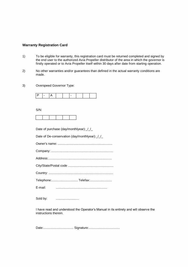
Warranty Registration Card 1) To be eligible for warranty, this registration card must be returned completed and signed by
the end user to the authorized Avia Propeller distributor of the area in which the governor is firstly operated or to Avia Propeller itself within 30 days after date from starting operation.
2) No other warranties and/or guarantees than defined in the actual warranty conditions are
made. 3) Overspeed Governor Type:
P - A -
S/N:
Date of purchase (day/monthlyear):_/_/_ Date of De-conservation (day/monthlyear):_/_/_ Owner's name: ............................................................ Company: .................................................................... Address:...................................................................... City/State/Postal code .................................................. Country: ....................................................................... Telephone:............................. Telefax:........................ E-mail: ........................................................ Sold by: ......................... I have read and understood the Operator’s Manual in its entirety and will observe the
instructions therein. Date:................................. Signature:..................................