Embed Size (px)
Citation preview
Operation & Maintenance Manual for
GPU-4060-T-CUP (& GPU-4060-T-CUP-28)
Ground Power Unit
CHAPTER 1
INFORMATION & OPERATION
Ground Power Unit
GPU-4060-CUP (Version: 200903)
Creation:03.09 — 2009 1-0-1 Contents
Chapter 1 Table of Contents
INFORMATION & OPERATION Chapter/Section Page
Description....................................................................................1-1 ..............................1 1. Unit Description .................................................................................................................... 1
A. GPU-4060......................................................................................................................... 1 2. Major Component Description.............................................................................................. 3
A. CUMMINS ENGINE:........................................................................................................ 3 B. Generator System............................................................................................................. 5 C. Control Box ....................................................................................................................... 7 D. GENERATOR CONTROL MODULE.............................................................................. 11 E. Instrument Panel............................................................................................................. 13 F. Contactors ...................................................................................................................... 16
Operation.......................................................................................1-2 ..............................1 1. Preparation for Use .............................................................................................................. 1
A. Inspection/Check .............................................................................................................. 1 B. Installing Output Cables.................................................................................................... 2
2. Unit Operation ...................................................................................................................... 3 A. Prestart Inspection............................................................................................................ 3 B. Engine Starting Procedures.............................................................................................. 3 C. Starting Engine in Cold Weather ...................................................................................... 3 D. Delivering Power to the Aircraft ........................................................................................ 3 E. Removing Power from the Aircraft................................................................................... 4 F. Shutting Down the Engine ............................................................................................... 4
Specifications and Capabilities...................................................1-3 ..............................1 1. GPU-4060 SERIES .............................................................................................................. 1
A. Generator Specifications .................................................................................................. 1 B. TLD Generator.................................................................................................................. 1 C. Generator Protective System ........................................................................................... 1 D. Engines: ............................................................................................................................ 2
2. CUMMINS ENGINE SPECIFICATION:................................................................................ 2 Shipping ........................................................................................1-4 ..............................1
1. Shipping the Unit .................................................................................................................. 1 A. Secure the unit.................................................................................................................. 1 B. Lifting Arrangements......................................................................................................... 1
Storage ..........................................................................................1-5 ..............................1 1. Storing the Unit..................................................................................................................... 1 2. Removing the Unit From Storage......................................................................................... 1
Creation:03.09 — 2009 1-1-1 Description
Description 1. Unit Description
A. GPU-4060
The GPU-4060 is a self contained, diesel engine driven, ground power unit. The unit is designed to supply regulated 400 Hz electrical power to a parked aircraft for operation of the aircraft's electrical equipment when the on-board generators are not running. The components of the GPU-4060 are of a simple but rugged design with sufficient safety devices to ensure a long, trouble free service life. The illuminated control panel provides for easy night operation.
The unit features a brush-less revolving field generator, rubber torsion axle-mounted chassis of rugged galvanized steel construction with fifth wheel steering and powder-coated sheet metal panels. The unit meets U.S. and EURO emission standards, Tier3 and Com 3.
Options available on the GPU-4060 Ground Power Unit are listed below. Each piece of optional equipment is covered by it's own instructions and parts breakdown and is located in Chapter 4. Disregard the option if not applicable to your unit.
(1) Low fuel warning with shutdown or idle
(2) Low fuel warning
(3) Engine block heater (120 VAC or 240 VAC)
(4) Amber or red, flashing, non-flashing, or rotating warning beacon
(5) 28.5 VDC Transformer rectifier package with current limiting, rated at 1000 amps continuous, 2500 amps peak
(6) Fuel filter / water separator with heater
(7) Hush kit
(8) Forklift safety pockets
(9) Plastic rub rails
Creation:03.09 — 2009 1-1-2 Description
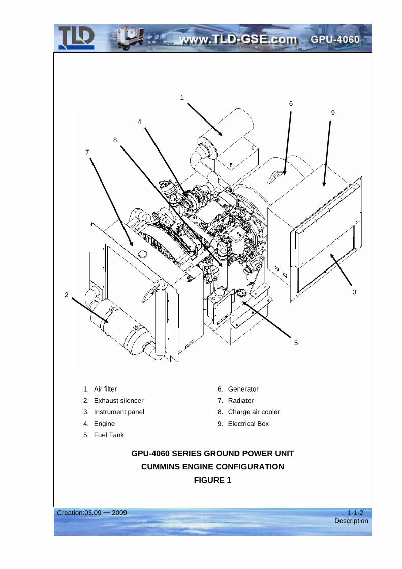
1. Air filter 6. Generator
2. Exhaust silencer 7. Radiator
3. Instrument panel 8. Charge air cooler
4. Engine 9. Electrical Box
5. Fuel Tank
GPU-4060 SERIES GROUND POWER UNIT CUMMINS ENGINE CONFIGURATION
FIGURE 1
9
8
7
6
5
4
32
1
Creation:03.09 — 2009 1-1-3 Description
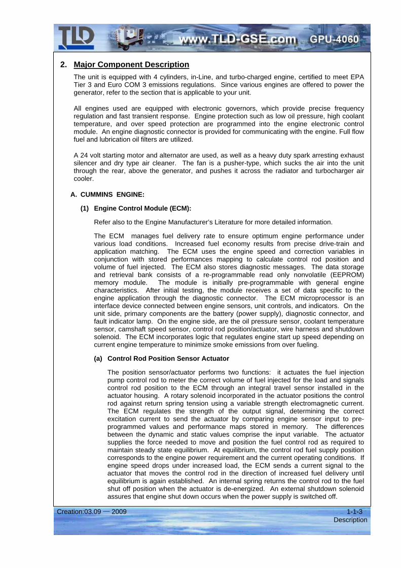
2. Major Component Description The unit is equipped with 4 cylinders, in-Line, and turbo-charged engine, certified to meet EPA Tier 3 and Euro COM 3 emissions regulations. Since various engines are offered to power the generator, refer to the section that is applicable to your unit.
All engines used are equipped with electronic governors, which provide precise frequency regulation and fast transient response. Engine protection such as low oil pressure, high coolant temperature, and over speed protection are programmed into the engine electronic control module. An engine diagnostic connector is provided for communicating with the engine. Full flow fuel and lubrication oil filters are utilized.
A 24 volt starting motor and alternator are used, as well as a heavy duty spark arresting exhaust silencer and dry type air cleaner. The fan is a pusher-type, which sucks the air into the unit through the rear, above the generator, and pushes it across the radiator and turbocharger air cooler.
A. CUMMINS ENGINE:
(1) Engine Control Module (ECM):
Refer also to the Engine Manufacturer’s Literature for more detailed information.
The ECM manages fuel delivery rate to ensure optimum engine performance under various load conditions. Increased fuel economy results from precise drive-train and application matching. The ECM uses the engine speed and correction variables in conjunction with stored performances mapping to calculate control rod position and volume of fuel injected. The ECM also stores diagnostic messages. The data storage and retrieval bank consists of a re-programmable read only nonvolatile (EEPROM) memory module. The module is initially pre-programmable with general engine characteristics. After initial testing, the module receives a set of data specific to the engine application through the diagnostic connector. The ECM microprocessor is an interface device connected between engine sensors, unit controls, and indicators. On the unit side, primary components are the battery (power supply), diagnostic connector, and fault indicator lamp. On the engine side, are the oil pressure sensor, coolant temperature sensor, camshaft speed sensor, control rod position/actuator, wire harness and shutdown solenoid. The ECM incorporates logic that regulates engine start up speed depending on current engine temperature to minimize smoke emissions from over fueling.
(a) Control Rod Position Sensor Actuator
The position sensor/actuator performs two functions: it actuates the fuel injection pump control rod to meter the correct volume of fuel injected for the load and signals control rod position to the ECM through an integral travel sensor installed in the actuator housing. A rotary solenoid incorporated in the actuator positions the control rod against return spring tension using a variable strength electromagnetic current. The ECM regulates the strength of the output signal, determining the correct excitation current to send the actuator by comparing engine sensor input to pre-programmed values and performance maps stored in memory. The differences between the dynamic and static values comprise the input variable. The actuator supplies the force needed to move and position the fuel control rod as required to maintain steady state equilibrium. At equilibrium, the control rod fuel supply position corresponds to the engine power requirement and the current operating conditions. If engine speed drops under increased load, the ECM sends a current signal to the actuator that moves the control rod in the direction of increased fuel delivery until equilibrium is again established. An internal spring returns the control rod to the fuel shut off position when the actuator is de-energized. An external shutdown solenoid assures that engine shut down occurs when the power supply is switched off.
Creation:03.09 — 2009 1-1-4 Description
(b) Engine Sensors
The engine sensors transmit data to the ECM describing engine dynamic performance. The sensors allow comparison of current engine operating conditions with specific parameters to determine the correct fuel delivery rate. Sensor inputs are supplied for control rod position, speed, coolant temperature, and oil pressure. The data received is used by the ECM to monitor and regulate engine performance, to provide diagnostic information, and to activate the engine protection system.
(c) Speed Sensor.
The engine speed sensor reads a pulse wheel on the camshaft to calculate engine speed. The ECM system provides over speed protection which retracts the control rod to the stop position and initiates a fault indication condition.
(d) Engine Protection Sensors.
The ECM records and displays engine fault conditions. The ECM continuously monitors input data received from the engine sensors and illuminates the engine fault, high coolant temperature, or low oil pressure light if a fault is detected. Automatic engine shutdown is programmed for low oil pressure and high coolant temperature conditions. Indicator lights on the instrument panel identify the specific fault condition. Transient overrun conditions will not cause engine shutdown. Active and inactive fault codes stores in the ECM’s memory can be accessed via the interface connector on the panel using a PC loaded with factory diagnosis software. Displayed information identifies the fault location; type of fault, engine speed and condition, number of fault locations, frequency and fault active or passive status.
Creation:03.09 — 2009 1-1-5 Description
B. Generator System
The GPU-4060 Series generator system is an extremely simple system which contains very few components. It can utilize either the TLD, Kato, or Marathon brand generators. All are direct drop-in replacements. The other major assembly of the generator system is the electrical box assembly, which contains the generator control module, instrument panel controls, and a relay panel.
1. Generator:
The 400 Hz generator is a brush-less, revolving field, three phase, synchronous, alternating current generator of single bearing construction. Generator excitation current is supplied from a direct connected brush-less rotating D.C. exciter. The generator stator core is constructed of one piece steel laminations. The steel laminations are assembled under pressure to form the stator core. The assembled core is rigidly welded to the frame ribs, and heavily insulated stator coils of the highest quality magnetic copper are then inserted in the stator slots. The stator core slots are insulated with the highest quality insulating material.
The complete assembly is vacuum pressure impregnated with epoxy resin and thermally cured to ensure excellent bonding qualities, high dielectric strength and maximum moisture resistance. The generator field poles are mounted on a large diameter shaft. Field coils of heavily insulated wire are machine wound directly onto the poles. The coils are blocked and braced for physical strength and rigidity. The entire rotor is vacuum pressure impregnated with 100% epoxy resin to form one complete, homogeneous mass. The exciter armature and rotating rectifier bridge assembly are sleeve mounted on the shaft of the synchronous generator. The rotating rectifier assembly consists of a full wave rectifier bridge made up of six semiconductor devices mounted on aluminum heat sink.
During operation, the three-phase power generated in the exciter armature is applied directly to the rotating rectifier assembly. The forward polarity rectifiers mounted on one heat sink and the reverse polarity rectifiers on the other heat sink are connected to form a three phase full wave rectifier bridge. The rotating rectifier bridge assembly rectifies the alternating current supplied by the exciter armature. The direct current output of the rotating rectifier bridge assembly is in turn applied to the rotating field of the generator via lead wires routed through a key way shaped slot on the rotor shaft. Excitation current for the stationary field coils is supplied by the synchronous generator through the Generator Control Module.
A heavy duty "greaseable" bearing is used to support the generator rotor for prolonged operating life. Grease fitting and grease relief are installed on the generator housing for easy lubrication of the bearing.
The generator is designed with a self-contained cooling system which circulates coolant air through the machine. Ambient air is drawn into the machine through louvered openings at the exciter end of the machine by a large capacity blower. The warm air is exhausted to the atmosphere through the screened opening enclosing the blower assembly. The complete generator is bolted to the engine flywheel housing.
In order to absorb the counter EMF which is present during NO BREAK POWER TRANSFER, a ring resistor (field discharge resistor) has been added across the main rotor windings, and over-sized diodes have also been added in the rotating rectifier assembly.
Creation:03.09 — 2009 1-1-6 Description
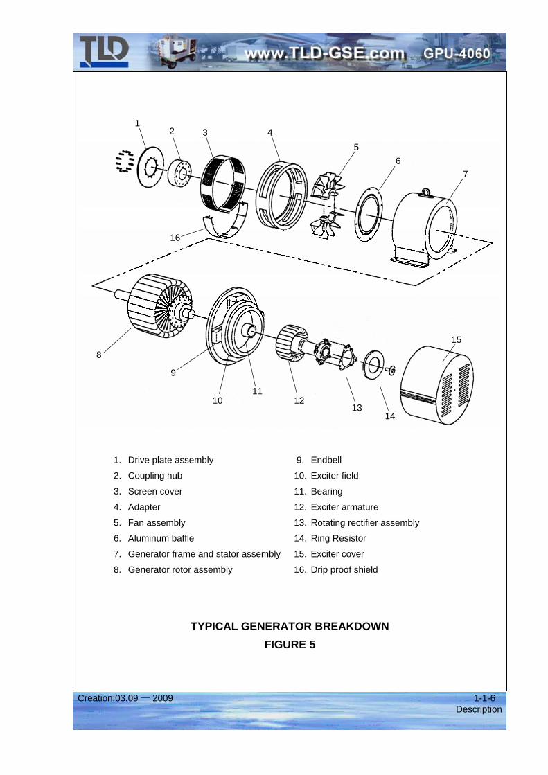
1. Drive plate assembly 9. Endbell
2. Coupling hub 10. Exciter field
3. Screen cover 11. Bearing
4. Adapter 12. Exciter armature
5. Fan assembly 13. Rotating rectifier assembly
6. Aluminum baffle 14. Ring Resistor
7. Generator frame and stator assembly 15. Exciter cover
8. Generator rotor assembly 16. Drip proof shield
TYPICAL GENERATOR BREAKDOWN FIGURE 5
16
543 2
1
6 7
1312
11
8
9
14
15
10
Creation:03.09 — 2009 1-1-7 Description
C. Control Box
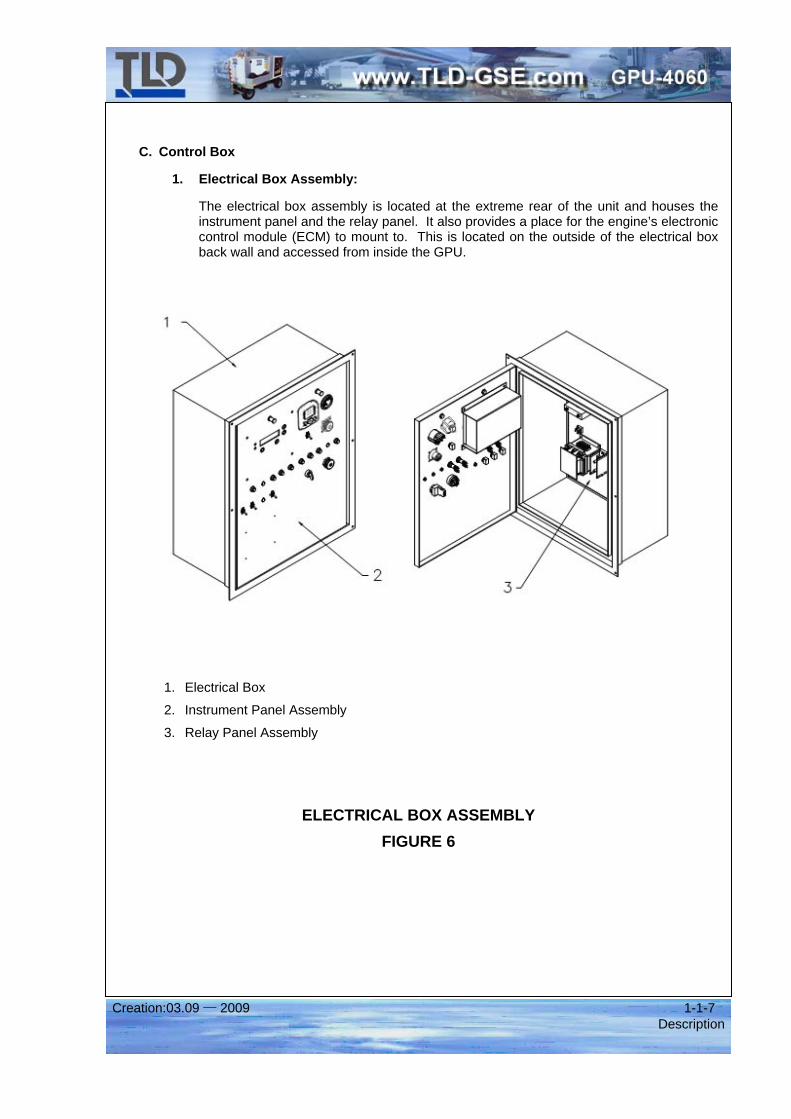
1. Electrical Box Assembly:
The electrical box assembly is located at the extreme rear of the unit and houses the instrument panel and the relay panel. It also provides a place for the engine’s electronic control module (ECM) to mount to. This is located on the outside of the electrical box back wall and accessed from inside the GPU.
1. Electrical Box
2. Instrument Panel Assembly
3. Relay Panel Assembly
ELECTRICAL BOX ASSEMBLY FIGURE 6
Creation:03.09 — 2009 1-1-8 Description
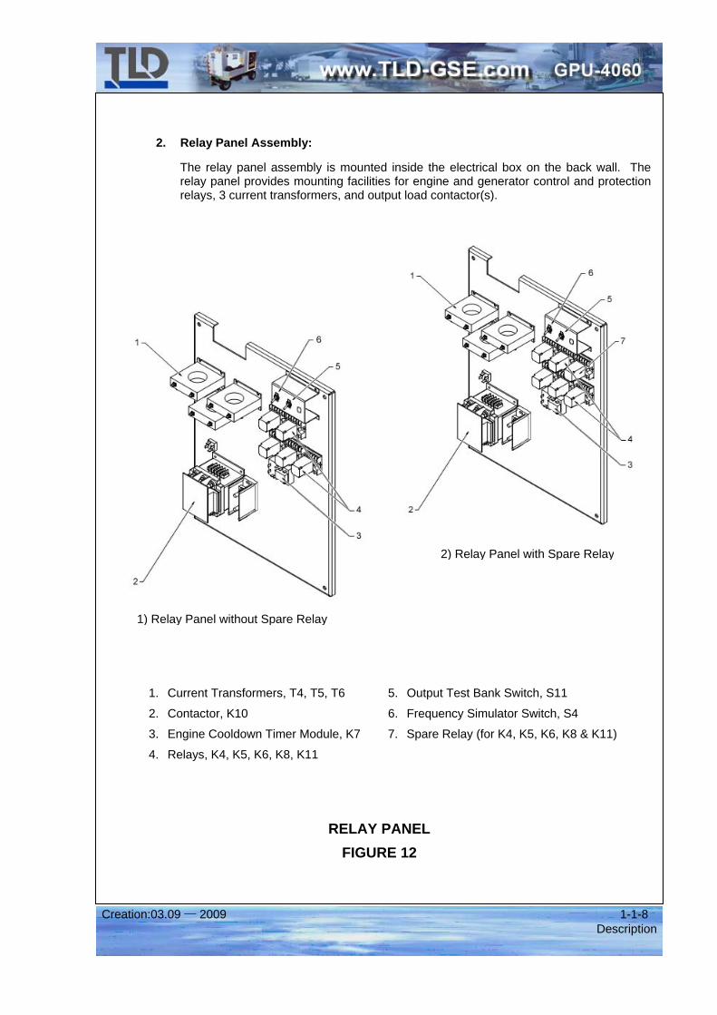
2. Relay Panel Assembly:
The relay panel assembly is mounted inside the electrical box on the back wall. The relay panel provides mounting facilities for engine and generator control and protection relays, 3 current transformers, and output load contactor(s).
1. Current Transformers, T4, T5, T6 5. Output Test Bank Switch, S11
2. Contactor, K10 6. Frequency Simulator Switch, S4
3. Engine Cooldown Timer Module, K7 7. Spare Relay (for K4, K5, K6, K8 & K11)
4. Relays, K4, K5, K6, K8, K11
RELAY PANEL FIGURE 12
1) Relay Panel without Spare Relay
2) Relay Panel with Spare Relay
Creation:03.09 — 2009 1-1-9 Description
The relay panel contains the following.
(1) Current Transformers, T4, T5, T6
The relay panel assembly contains 3 current transformers which are used to transform current measurements to mili-volt signals to the Generator Control Module (GCM) for load sensing and line drop compensation, for instrument panel indication, and for over-current protection.
(2) Contactor(s), K10
The function of the contactors is to allow, or not allow, 400 Hz output power from the generator to the aircraft. The contacts state, open or closed, is controlled by the 28 VDC contactor coil.
(3) Output Plug Interlock Relay(s) and Circuit Description, K11
The function of the plug interlock relay(s) is to cause the output load contactor to open, via the generator control module (GCM) in the event the cable plug connector becomes accidentally disconnected from the aircraft during power delivery, or if an attempt is made to deliver power when the output cable is not connected to the aircraft, or if the aircraft should reject the GPU’s 400 Hz power for any reason. 28 VDC for operation of the relay is supplied from the aircraft either through an on-board transformer-rectifier or from a 28 VDC electrical system. Connection from the aircraft to the interlock relay is made through terminals E and F on the output cable plug connector.
(4) Output Test Bank Switch(es), S11
A SPST, toggle switch provides a means of bypassing the plug interlock relay when supplying power to a load bank or to an aircraft not equipped with 28 VDC feedback.
(5) Starter Lockout Relay, K8
The function of the starter lockout relay is to not allow the engine’s starter motor to crank when it is already running.
(6) Idle / Rated Speed Relay, K5
The function of the idle/rated speed relay is to allow the engine to run either at idle speed or rated speed. When the idle/rated speed relay is de-energized, the engine is running at idle speed. When the idle/rated speed relay is energized, it sends a signal to the speed control unit, allowing the governor actuator to bring the shut off lever to the rated speed position.
(7) Engine Fault Relay, K4
The function of the engine fault relay is to make the engine go back to idle should an engine fault, such as low oil pressure or high coolant temperature occur. When any of the above conditions develop, the engine fault relay is de-energized by the Deutz ECM, which opens the K4 engine fault relay contact, cutting power to the K5 rated speed relay. This causes 2 things to happen. First, it tells the Deutz ECM to go to idle engine speed. Second, it cuts power to the Generator Control Module (GCM), which cuts the signal to the generator field and causes 400 Hz output power to stop.
(8) Engine Cooldown Relay, K6
The purpose of the Engine Cooldown Idle Relay is to ensure the engine goes to idle for a period of 1 minute prior to shutting down. This is a standard feature of the GPU-4060 series Ground Power Units designed to protect the engine’s turbo from rapid temperature changes. It will greatly improve the longevity of the engine and it’s logic must not be defeated, Nor should the emergency stop switch be used to shutdown the engine under normal operation.
Creation:03.09 — 2009 1-1-10 Description
(9) Engine Cooldown Timer Module, K7
The purpose of the Engine Cooldown Timer Module is to perform the acutal timing of the Engine Cooldown Circuit. When the engine is running and the ignition switch is moved to the off position, power is cut ot the “initiate” contact of this relay. One minute after, this relay will go back to it’s original state and cut power to the 24 VDC run circuit, cutting power to the engine’s ECM and shutting off the unit.
On startup, there is no timing feature.
(10) Frequency Simulator Switch, S4
The frequency Simulator Switch is a single-pole, double-throw, switch with momentary contacts used for maintenance purposes only. It functions to increase or decrease the engine’s speed by sending a signal to the appropriate contact on the engine’s ECM. When the engine’s speed is increased, the generator’s output frequency is also increased, and visa versa. This switch is used to ensure the generator control module (GCM) causes the output contactor(s) to open anytime the frequency goes over 420 Hz or falls under 380 Hz.
(11) Bridge Rectifier, CR1
The function of the bridge rectifier(s) is to convert a 115 VAC signal to 28 VDC to energize the unit’s main output load contactor(s).
(12) Terminal Boards, TB1, TB2, TB3, TB4, TB5
The purpose of the terminal boards is to provide a means to interconnect power from 1 wire or cable to another. TB5 is for connecting the 400 Hz output cable(s) Neutral wire “N” to the Generator “N” cable. TB6 connect the output cable(s) E and F pins to the K11 output plug interlock relay coil. TB9 is to allow connecting of the optional 28.5 VDC circuit.
Note that there is no Terminal Board for connecting output cable(s) for lines A, B, or C. These are connected directly into the output contactor(s) respective contact.
(13) Spare Relay
The purpose of the Spare Relay is disconnected and provides to replace any of the failure relays (for K4, K5, K6, K8 & K11).
Creation:03.09 — 2009 1-1-11 Description
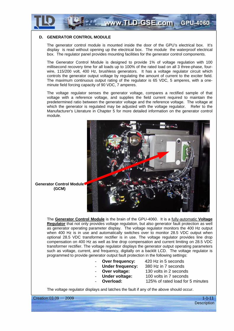
D. GENERATOR CONTROL MODULE
The generator control module is mounted inside the door of the GPU’s electrical box. It’s display is read without opening up the electrical box. The module the waterproof electrical box. The regulator panel provides mounting facilities for the generator control components.
The Generator Control Module is designed to provide 1% of voltage regulation with 100 millisecond recovery time for all loads up to 100% of the rated load on all 3 three-phase, four-wire, 115/200 volt, 400 Hz, brushless generators. It has a voltage regulator circuit which controls the generator output voltage by regulating the amount of current to the exciter field. The maximum continuous output rating of the regulator is 65 VDC, 5 amperes, with a one-minute field forcing capacity of 90 VDC, 7 amperes.
The voltage regulator senses the generator voltage, compares a rectified sample of that voltage with a reference voltage, and supplies the field current required to maintain the predetermined ratio between the generator voltage and the reference voltage. The voltage at which the generator is regulated may be adjusted with the voltage regulator. Refer to the Manufacturer's Literature in Chapter 5 for more detailed information on the generator control module.
The Generator Control Module is the brain of the GPU-4060. It is a fully-automatic Voltage Regulator that not only provides voltage regulation, but also generator fault protection as well as generator operating parameter display. The voltage regulator monitors the 400 Hz output when 400 Hz is in use and automatically switches over to monitor 28.5 VDC output when optional 28.5 VDC transformer rectifier is in use. The voltage regulator provides line drop compensation on 400 Hz as well as line drop compensation and current limiting on 28.5 VDC transformer rectifier. The voltage regulator displays the generator output operating parameters such as voltage, current, and frequency, digitally on a backlit LCD. The voltage regulator is programmed to provide generator output fault protection in the following settings:
- Over frequency: 420 Hz in 5 seconds - Under frequency: 380 Hz in 7 seconds - Over voltage: 130 volts in 2 seconds - Under voltage: 100 volts in 7 seconds - Overload: 125% of rated load for 5 minutes
The voltage regulator displays and latches the fault if any of the above should occur.
Generator Control Module (GCM)
Creation:03.09 — 2009 1-1-12 Description
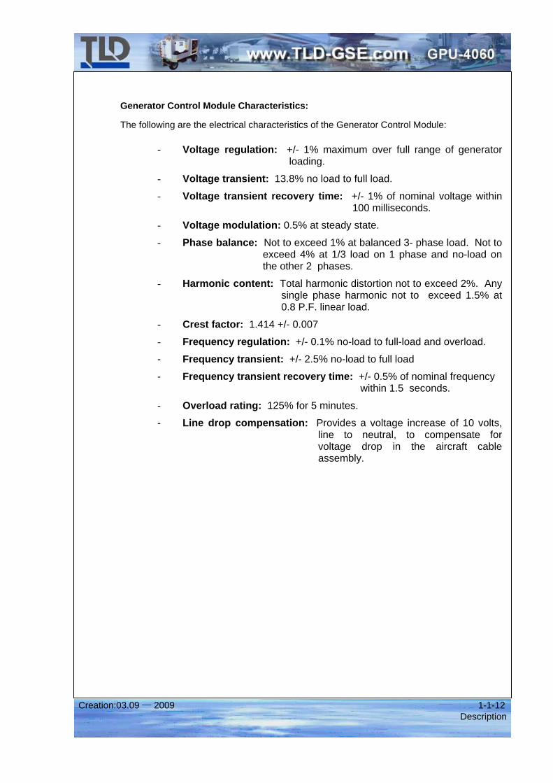
Generator Control Module Characteristics:
The following are the electrical characteristics of the Generator Control Module:
- Voltage regulation: +/- 1% maximum over full range of generator loading.
- Voltage transient: 13.8% no load to full load.
- Voltage transient recovery time: +/- 1% of nominal voltage within 100 milliseconds.
- Voltage modulation: 0.5% at steady state.
- Phase balance: Not to exceed 1% at balanced 3- phase load. Not to exceed 4% at 1/3 load on 1 phase and no-load on the other 2 phases.
- Harmonic content: Total harmonic distortion not to exceed 2%. Any single phase harmonic not to exceed 1.5% at 0.8 P.F. linear load.
- Crest factor: 1.414 +/- 0.007
- Frequency regulation: +/- 0.1% no-load to full-load and overload.
- Frequency transient: +/- 2.5% no-load to full load
- Frequency transient recovery time: +/- 0.5% of nominal frequency within 1.5 seconds.
- Overload rating: 125% for 5 minutes.
- Line drop compensation: Provides a voltage increase of 10 volts, line to neutral, to compensate for voltage drop in the aircraft cable assembly.
Creation:03.09 — 2009 1-1-13 Description
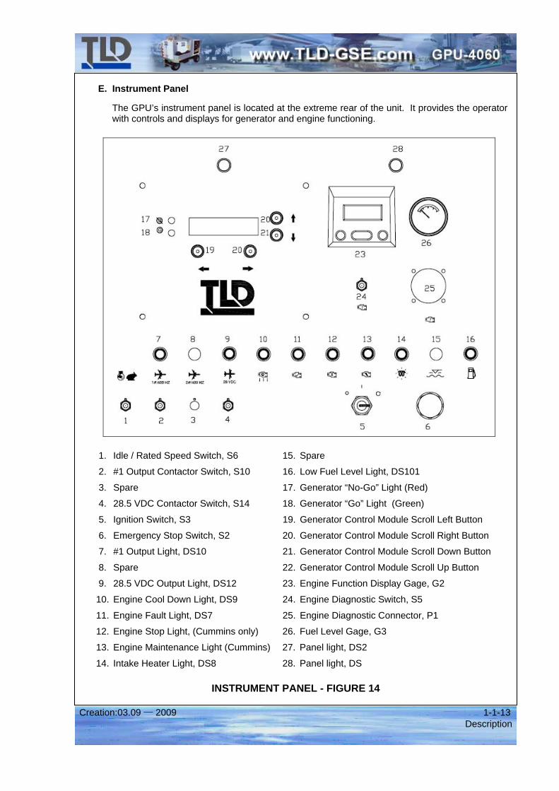
E. Instrument Panel
The GPU’s instrument panel is located at the extreme rear of the unit. It provides the operator with controls and displays for generator and engine functioning.
1. Idle / Rated Speed Switch, S6 15. Spare
2. #1 Output Contactor Switch, S10 16. Low Fuel Level Light, DS101
3. Spare 17. Generator “No-Go” Light (Red)
4. 28.5 VDC Contactor Switch, S14 18. Generator “Go” Light (Green)
5. Ignition Switch, S3 19. Generator Control Module Scroll Left Button
6. Emergency Stop Switch, S2 20. Generator Control Module Scroll Right Button
7. #1 Output Light, DS10 21. Generator Control Module Scroll Down Button
8. Spare 22. Generator Control Module Scroll Up Button
9. 28.5 VDC Output Light, DS12 23. Engine Function Display Gage, G2
10. Engine Cool Down Light, DS9 24. Engine Diagnostic Switch, S5
11. Engine Fault Light, DS7 25. Engine Diagnostic Connector, P1
12. Engine Stop Light, (Cummins only) 26. Fuel Level Gage, G3
13. Engine Maintenance Light (Cummins) 27. Panel light, DS2
14. Intake Heater Light, DS8 28. Panel light, DS
INSTRUMENT PANEL - FIGURE 14
Creation:03.09 — 2009 1-1-14 Description
The following instruments and control switches are mounted on the instrument panel.
(1) Idle / Rated Speed Switch
The engine idle / rated speed switch is a three position toggle switch identical to the output contactor switches. The lower position of the switch is for idle engine speed and the center position of the switch is for full engine speed. Both of these positions are maintained contacts.
The top position of the switch is a momentary contact and is used to turn on the generator control module which then allows the generator to build up voltage. At this point, 400 Hz power is available at the generator side of the output load contactor(s), but no further. When the switch is released, it will automatically return to the rated speed position.
In the OFF position, the switch opens the AC circuit to the rectifier bridge, thereby cutting the DC power to the contactor coil. This causes the output load contactor to open.
(2, 3) Output Contactor Switches
The output contactor switches are three position toggle switch identical to the idle/rated speed switch. When held in the momentary CLOSE position, it provides 400 Hz power directly to a rectifier bridge, which supplies DC power to the respective contactor coils for closing the output contactors. When released, it returns to the normal ON position and continues to allow power to go to the rectifier bridge, but in this switch position, AC power must pass through the plug interlock relay contacts, K11 & K13, and the generator control module, VR1.
(4) 28.5 VDC Contactor Switch (optional)
The 28.5 VDC contactor switch functions the same way as the 400 Hz output contactor switches except it controls the 28.5 VDC output load contactor.
(5) Ignition Switch
The ignition switch is used to turn the GPU on and off by controlling power to the engine’s Electronic Control Module (ECM).
(6) Emergency Stop Switch
The emergency stop switch cuts battery power to the engine ECM and the Generator Control Module, and will shut the GPU off.
THE EMERGENCY STOP SWITCH MUST ONLY BE USED IN AN EMERGENCY SITUATION AND NOT FOR NORMAL GPU USE.
(7) #1 Output Light
The #1 output light will illuminate whenever 400 Hz power is traveling accross the #1 output load contactor.
(8) Spare
(9) 28.5 VDC Output Light (optional)
The 28.5 VDC output light will illuminate whenever 28.5 VDC travels accross the 28.5 VDC output load contactor.
Creation:03.09 — 2009 1-1-15 Description
(10) Engine Cool Down Light
The engine cool down light will illuminate whenever the engine cooldown relay, K6, is de-energized. This relay is engergized during normal engine running operation and no power is allowed to the light. When the ignition switch is moved to the off position, power is cut from the cooldown timer module, at which time, it’s contacts open after a predetermined time, removeing power to the engine’s ECM and shutting down the engine. THIS CIRCUIT WILL INCREASE THE LIFE OF THE ENGINE AND TURBO.
(11) Engine Fault Light
The engine fault light is controlled by the engine’s electronic control module (ECM) and it will illuminate anytime a fault is detected via the engine’s safety sensors. It is also used to flash diagnostic codes.
(12) Engine Stop Light (Cummins Only)
The engine stop light is used to notify the operator of a critical engine condition and the engine should be shut down immediately. The cause of the fault must be determined and fixed prior to the unit being put back into service.
(13) Engine Maintenance Light (Cummins Only)
The engine maintenance light signals to the operator that the engine is due for routine maintenance.
(14) Engine Intake Heater Light
When the ignition switch is turned to the "run” position, the intake manifold heater will turn on until the temperature rises above the required temperature.
The illumination of the intake heater light indicates that the pre-heating is taking place. Wait until the light goes out, then follow the normal starting procedure.
(15) Spare
(16) Low Fuel Level Light
The low fuel level light will illuminate when the level of fuel in the tank falls below approximately ¼ full which causes
(18) Fuel Level Gage
The fuel level gage is an electrical type. It receives signals from the fuel level sender mounted in the fuel tank. The gauge indicates the fuel level in the fuel tank.
(21) Ignition Switch
The ignition switch serves to connect power to the auxiliary starter relay, K2, which then allows power to go to the starter relay, K1. Battery voltage is then applied to the starter motor which engages the starter gear with the flywheel ring gear and cranks the engine.
(27,28) Panel Lights
The panel lights provided illumination to the instrument panel for night time operation.
Creation:03.09 — 2009 1-1-16 Description
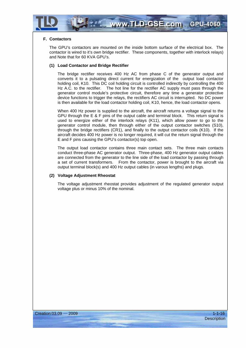
F. Contactors
The GPU’s contactors are mounted on the inside bottom surface of the electrical box. The contactor is wired to it’s own bridge rectifier. These components, together with interlock relays) and Note that for 60 KVA GPU’s.
(1) Load Contactor and Bridge Rectifier
The bridge rectifier receives 400 Hz AC from phase C of the generator output and converts it to a pulsating direct current for energization of the output load contactor holding coil, K10. This DC coil holding circuit is controlled indirectly by controlling the 400 Hz A.C. to the rectifier. The hot line for the rectifier AC supply must pass through the generator control module’s protective circuit, therefore any time a generator protective device functions to trigger the relays, the rectifiers AC circuit is interrupted. No DC power is then available for the load contactor holding coil, K10, hence, the load contactor opens.
When 400 Hz power is supplied to the aircraft, the aircraft returns a voltage signal to the GPU through the E & F pins of the output cable and terminal block. This return signal is used to energize either of the interlock relays (K11), which allow power to go to the generator control module, then through either of the output contactor switches (S10), through the bridge rectifiers (CR1), and finally to the output contactor coils (K10). If the aircraft decides 400 Hz power is no longer required, it will cut the return signal through the E and F pins causing the GPU’s contactor(s) top open.
The output load contactor contains three main contact sets. The three main contacts conduct three-phase AC generator output. Three-phase, 400 Hz generator output cables are connected from the generator to the line side of the load contactor by passing through a set of current transformers. From the contactor, power is brought to the aircraft via output terminal block(s) and 400 Hz output cables (in varous lengths) and plugs.
(2) Voltage Adjustment Rheostat
The voltage adjustment rheostat provides adjustment of the regulated generator output voltage plus or minus 10% of the nominal.
Creation:03.09 — 2009 1-2-1 Operation
Operation
1. Preparation for Use
A. Inspection/Check
Inspect the unit thoroughly prior to operation.
(1) Remove the blocking, banding, ties, and other securing material.
(2) Inspect for shipping damage.
(3) Inspect the interior for foreign material such as rags, shipping papers, etc.
(4) Check the fuel, coolant and oil hoses and connections for visible leaks.
(5) Check the following for sufficient quantity. (a) Fuel
The level gauge should be at or near full.
(b) Engine coolant
Coolant level should be approximately one inch below the radiator filler neck. The expansion tank should be approximately half full.
(c) Engine Lubricating Oil
The oil level should be at the full mark on the dipstick. See the “Cummins Engine” manual for oil recommendations.
WARNING: IMPROPER OPERATION CAN KILL! READ AND UNDERSTAND ALL OF THE OPERATING INSTRUCTIONS BEFORE ATTEMPTING TO OPERATE THE UNIT.
CAUTION: BE SURE THE COOLANT SYSTEM ANTI-FREEZE SOLUTION IS ADEQUATE TO PROTECT BELOW THE LOWEST TEMPERATURE EXPECTED.
NOTE: For antifreeze protection use a solution of 50% permanent antifreeze (ethylene glycol) and 50% clean water.
Creation:03.09 — 2009 1-2-2 Operation
(d) Air Cleaner The air cleaner is a disposable dry type with an integral filter element. Check to ensure there are no papers, tape, or other material covering the air inlet.
B. Installing Output Cables
Units are generally shipped without aircraft cable assembly.
(1) Three-phase AC Aircraft Cable Assembly Installation (#1 Output)
The output terminal is located at the left rear of the electrical box.
(a) Loosen the cable clamp and connect the loose ends of the cable assembly to the output terminal.
(b) Each terminal stud is identified by a nameplate. Each cable should be identified by a band-type marker. Connect cable "A" to terminal "A", "B” to "B", etc. Tighten the terminal nuts securely. Connect "E" lead to "E" terminal and "F" lead to "F" terminal.
(c) Tighten the cable clamps securely but avoid damage to the cable insulation.
NOTE: The AC aircraft cable assembly recommended shall consist of four single conductor #2/0 cables with two #12 control leads connected to an AN3430 plug.
Creation:03.09 — 2009 1-2-3 Operation
2. Unit Operation
This section contains information and instructions for the safe and efficient operation of the unit.
A. Prestart Inspection
(1) Check the engine oil level.
(2) Check the coolant level.
(3) Make a visual check of the unit for conditions which could affect serviceability.
B. Engine Starting Procedures
The engine and generator operating controls and monitoring equipment are mounted on the instrument panel as illustrated in Figure 14.
(1) Turn the ignition switch to the "START" position.
(2) Release the ignition switch when the engine starts.
(3) The engine is now running at idle speed. Let the engine warm up to the operating temperature.
(4) Hold the engine switch in the “"UP" position momentarily to bring the engine to operating speed abd to build up generator voltage.
C. Starting Engine in Cold Weather
This engine is equipped with an automatic intake manifold heater. Pre-heating to the heater takes place automatically when the engine ambient temperature reaches a predetermined value.
The heater light illustrates when pre-heating is taking place. Wait until the heater light goes out then follow the normal starting procedure.
D. Delivering Power to the Aircraft
(1) Connect the power cable to the AC external power receptacle on the aircraft.
(2) Hold the contactor switch (#1 output) in the "CLOSE" position.
(3) When the output lamp (#1) lights, release the contactor switch.
(4) External power is now being supplied to the aircraft.
WARNING: IMPROPER OPERATION CAN KILL! READ AND UNDERSTAND ALL OF THE OPERATING INSTRUCTIONS BEFORE ATTEMPTING TO OPERATE THE UNIT.
NOTE: Always wait until the heater light goes out then start the engine to ensure a successful and clean start.
Creation:03.09 — 2009 1-2-4 Operation
E. Removing Power from the Aircraft
(1) Place the contactor switch in the "OFF" position.
(2) Disconnect the power cable from the aircraft.
(3) Stow the power cable on the generator in the proper location.
F. Shutting Down the Engine
(1) Turn the ignition switch to “OFF” position. The engine will ramp down to idle and remain in idle for approximately one (1) minute to cool down. It will then shut down automatically.
CAUTION: FAILURE TO ALLOW THE ENGINE TO IDLE AFTER OPERATING UNDER LOAD MAY LEAD TO TURBOCHARGER BEARING DAMAGE.
DO NOT USE THE EMERGENCY STOP SWITCH TO SHUT DOWN THE UNIT DURING NORMAL OPERATION.
Creation:03.09 — 2009 1-3-1 Specifications & Capabilities
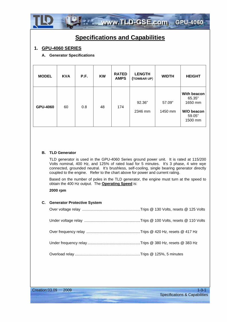
Specifications and Capabilities 1. GPU-4060 SERIES
A. Generator Specifications
MODEL KVA P.F. KW RATED AMPS
LENGTH (TOWBAR UP) WIDTH HEIGHT
GPU-4060 60 0.8 48 174 92.36”
2346 mm
57.09”
1450 mm
With beacon
65.35" 1650 mm
W/O beacon
59.05” 1500 mm
B. TLD Generator
TLD generator is used in the GPU-4060 Series ground power unit. It is rated at 115/200 Volts nominal, 400 Hz, and 125% of rated load for 5 minutes. It’s 3 phase, 4 wire wye connected, grounded neutral. It’s brushless, self-cooling, single bearing generator directly coupled to the engine. Refer to the chart above for power and current rating.
Based on the number of poles in the TLD generator, the engine must turn at the speed to obtain the 400 Hz output. The Operating Speed is:
2000 rpm
C. Generator Protective System
Over voltage relay .......................................................Trips @ 130 Volts, resets @ 125 Volts
Under voltage relay .....................................................Trips @ 100 Volts, resets @ 110 Volts
Over frequency relay ...................................................Trips @ 420 Hz, resets @ 417 Hz
Under frequency relay ..................................................Trips @ 380 Hz, resets @ 383 Hz
Overload relay ..............................................................Trips @ 125%, 5 minutes
Creation:03.09 — 2009 1-3-2 Specifications & Capabilities
D. Engines:
All engines used are fully-electronic diesel engines with electronic engine governors provide precise frequency regulation and fast transient response. Engine protection such as low oil pressure, high coolant temperature, and over speed protection are programmed into the engine electronic control module. An engine diagnostic connector is provided for communicating with the engine. Engine operating parameters are displayed with electronic gages via SAE J1939 Controller Area Network, which include:
- Engine Hours - Engine RPM - System Voltage - Oil Pressure - Coolant Temperature - % Engine Load at the current RPM - Active and stored Service Codes - View Engine Configuration Parameters
A separate analog fuel gage is provided automatic engine cool down and emergency shutdown are standard engine controls.
2. CUMMINS ENGINE SPECIFICATION: Manufacturer ..................................................................Cummins
Model .............................................................................QSB4.5
Type ...............................................................................Turbocharged, in-line, 4 Cylinder 4-cycle diesel
Gross Rated Horsepower @ governed speed...............130HP/97KW
Governed speed.............................................................2000 RPM
Firing order.....................................................................1-3-4-2
Electrical system ............................................................24 Volt, negative ground
Refer to chapter 5 (manufacturer’s literature) for details of Cummins QSB4.5 engine.
Creation:03.09 — 2009 1-4-1 Shipping
Shipping 1. Shipping the Unit
A. Secure the unit
Using straps or chains over the axels. Use wheel chocks in front of and behind the tires to prevent movements.
B. Lifting Arrangements
If it is desired to lift the unit with a forklift, certain precautions are necessary to prevent damage to the unit. The forks must be positioned so that they extend far enough under the unit to provide a stable lift. The bottom of the unit is flat across the bottom of the cable tray and fuel tank and no blocking or spacers are required.
CAUTION: DO NOT SHIP THE UNIT BY RAIL. DAMAGE MAY OCCUR DUE TO HIGH AND UNPREDICTABLE ACCELERATION WHEN SHIPPING BY RAIL AND THE FACTORY SUGGESTS THAT OTHER MODES OF TRANSPORTATION BE USED.
CAUTION: DO NOT USE CHAINS OR STRAPS OVER FUEL LINES, ELECTRICAL WIRES, OR COMPONENTS.
NOTE: If shipping the unit by boat it is advisable to keep the unit below decks and away from salt water spray. If this is unavoidable, cover the unit with plastic to keep salt water spray from coming in contact with the unit.
Creation:03.09 — 2009 1-5-1 Storage
Storage 1. Storing the Unit
A. When storing the unit in cold ambient temperatures be sure that the proper glycol percentage is present in the engine cooling system.
B. When storing the unit for extended periods of time, perform the following steps:
(1) Drain the cooling system completely from the engine and radiator.
(2) Remove most of the weight from the tires using blocks under the frame.
Remove all fuel from the fuel tank and add a desiccant to absorb condensation.
Cover the air screens on the generator with tape to prevent the access of freign material.
2. Removing the Unit From Storage
A. Check and replenish the level of engine coolant.
B. Check and replenish the level of oil in the engine.
C. Remove the tape on the generator air screens.
D. Remove the tape on the generator air screens.
E. Make a visual check of the unit as birds and small rodents may build nests or chew on wires and hoses.
NOTE: Consult the manufacturer's literature in Chapter 5 for further Information on storage.
NOTE: Consult the manufacturer's literature in Chapter 5 for further Information on removing components from storage.