Embed Size (px)
Citation preview
Printed in Japan Pub. No.
Pub. N
o.
OPERATION &
OPERATION&M
AINTENANCE MANUAL
MAINTENANCE MANUAL
Pub. No.
The operator and supervisor are requested to read this Oper-ation and Maintenance Manual carefully before operating theengine or conducting inspection and maintenance.Never operate the engine or conduct maintenance work with-out completely understanding this manual.
Novem
ber 2007
November 2007
99610-15130
99610-15130
99610-15130


Pub. No. 99610-15130
FOREWORD
This operation and maintenance manual contains detailed operation, inspection and maintenance information for Mitsubishi engines.
Please read this manual thoroughly before proceeding with operation, inspection, and maintenance work for correct use and servicing.
Failure to follow directions in this manual may result in serious accidents.
i

FOREWORD
Limited warranty
The manufacturer will repair or replace parts returned to the manufacturer when the manufacturer judges after inspection that the parts are defective in material and/or workmanship. The manufacturer's warranty is limited to the repair work or replacement of parts for the defective parts only. The warranty coverage is effective for the original purchaser only. Those to whom ownership is later transferred are not provided with the warranty.
• The manufacturer makes no warranties, either expressed or implied, except as provided in thismanual, including, but not limited to, warranties as to marketability, merchantability, fitness for aparticular purpose or use, or against infringement of any patent.
• The manufacturer will not be liable for any damages or consequential damages, including, butnot limited to, damages or other costs resulting from any abuse, misuse, misapplication of theengine and devices supplied by the manufacturer.
• The manufacturer will not be liable for any damages or personal injuries resulting from anymodification, without the manufacturer's written permission, of the engine and devices suppliedby the manufacturer.
• The manufacturer will not be liable for any damages or production losses caused by the use offuel, engine oil and/or long life coolant (LLC) that are not recommended by the manufacturer.
• The owner of the engine is responsible for the performance of the required maintenance listedin this operation manual. The manufacturer may deny the warranty coverage if the engine orpart has failed due to inadequate or improper maintenance.
ii

FOREWORD
Emission warranty
The following warranty applies to the engines that are approved of the emission regulation of the U.S Environmental Protection Agency.
Warranty coverageMitsubishi Heavy Industries warrants to the first owner and each subsequent purchaser of a new L series diesel engine that the emission control system of your engine:• is designed, built and equipped so as to conform at the time of sales with all applicable regulation of the U.S Envi-
ronmental Protection Agency. If the vehicle in which the engine is installed is registered in the sate of California, a separate California emission regulation also applies.
• is free from the defects in material and workmanship which will cause the engine to fail to meet these regulations within the warranty period.
Warranty periodThe emission warranty period is shown below.However, if your engine warranty period is longer than the emission warranty period, the emission warranty period extends to same as the engine warranty period.Below warranty period shall begin on the date the engine is delivered to the first owner.
Warranted partsMitsubishi Heavy Industries warrants the parts which will increase the emission of pollutants when they become defective.The followings are examples.• Inlet/Exhaust manifold• Crankcase ventilation system• Fuel system• Fuel injection nozzle
Limited warrantyRefer to "Limited warranty"
If your engine is certified as And its maximum power is And its rated speed is Then its warranty period is
Variable speed or constant speed kW < 19 Any speed 1,500 hours or two years, whichever comes first.
Constant speed 19 ≤ kW < 37 3,000 min-1 or higher1,500 hours or two years, whichever
comes first.
Constant speed 19 ≤ kW < 37 Less than 3,000 min-1 3,000 hours or five years, whichever comes first.
Variable speed 19 ≤ kW < 37 Any speed 3,000 hours or five years, whichever comes first.
Variable speed or constant speed kW ≥ 37 Any speed 3,000 hours or five years, whichever comes first.
iii
FOREWORD
Important information
• To avoid potential hazard, accident prevention activ-ities must be planned methodically and conducted continually by considering all aspects of engine operation, maintenance and inspection.All related personnel, including managers and supervisors, should actively participate, recognize their roles and organize themselves and their work to ensure a safe environment.
• The foremost safety objective is to prevent acci-dents that may result in injury or death, or equip-ment damage.
• Always observe laws or regulations of the local or federal/national government.
• The manufacturer cannot foresee all potential dan-gers of the engine, potential danger resulting from human error and other causes, or danger caused by a specific environment in which the engine is used.Since there are many actions that cannot be per-formed or must not be performed, it is impossible to indicate every caution in this manual or on warning labels. As such, it is extremely important to follow directions in this manual and also to take general safety measures when operating, maintaining and inspecting the engine.
• This manual has been prepared for people whose native language is English. When the engine is used by individuals whose native language is not English, the customer is requested to provide thorough safety guidance to the operators. Also add safety, caution and operating signs that describe the origi-nal warning label statements in the native language of the operators.
• The engine must be operated, maintained and inspected only by qualified persons who have thor-ough knowledge of engines and their dangers and who also have received risk avoidance training.
• To prevent an accident, do not attempt to carry out any operation other than those described in this manual, and do not use the engine for any unap-proved purpose.
• When the ownership of the engine is transferred, be sure to provide this manual with the engine to the new owner. Also inform the manufacturer of the name and address of the new owner of the engine.
• This manual is copyrighted and all rights are reserved. No part of this manual, including illustra-tions and technical references, may be reproduced, photocopied, translated, or reproduced in any elec-tronic medium or machine readable form without prior written consent from the manufacturer.
• The contents in this manual are subject to change at any time without notice, for improvement of the engine.
• Pictures or illustrations of the product in this manual may differ from those of product you have.
• Please note that, depending on specifications, items described in this manual may differ in shape, or may not be installed on the product you have.
• Please contact your Mitsubishi dealer if you need more information or if you have any questions.
• If you lose or damage this manual, obtain a new copy at your Mitsubishi dealer as soon as possible.
• Mitsubishi Heavy Industries recommends the engine owner to install an hourmeter on the engine due to monitor correct service intervals and to per-form the maintenance at the proper timing.
iv
FOREWORD
Warning Indication
The following two means are used to call the attention of the operators and maintenance personnel to potential dan-gers of the engine.• Warning statements in the manual• Warning labels affixed on the engine
Warning statementsThe warning statements in this manual describe potential danger in operating, inspecting or maintaining the engine, using the following five classifications to indicate the degree of potential hazard. Failure to follow these directions could lead to serious accidents which could result in personal injury, or death in the worst case.
Indicates an imminently hazardous situation which, if not avoided, will result in death or serious injury.
Indicates a potentially hazardous situation which, if not avoided, could result in death or serious injury.
Indicates a potentially hazardous situation which, if not avoided, may result in minor or moderate injury.
Indicates a potentially hazardous situation which, if not avoided, can result in property damage.
Note: Indicates important information or information which is useful for engine operation.
v

FOREWORD
Units of measurement
Measurements are based on the International System of Units (SI), and they are converted to the metric system units in this manual using the following conversion rates.• Pressure: 1 MPa = 10.197 kgf/cm2
• Torque: 1 N⋅m = 0.10197 kgf⋅m• Force: 1 N = 0.10197 kgf• Horsepower: 1 kW = 1.341 HP = 1.3596 PS• Meter of mercury: 1 kPa = 0.75 cmHg• Meter of water: 1 kPa = 10.197 cmH2O (cmAq)• Engine speed: 1 min-1 = 1 rpm
Abbreviations, standards and others
• API = American Petroleum Institute• ASTM = American Society for Testing and Materials• JIS = Japanese Industrial Standards• LLC = Long Life Coolant• MIL = Military Specifications and Standards (U.S.A.)• MSDS = Material Safety Data Sheet• SAE = Society of Automotive Engineers (U.S.A.)
vi

CONTENTS
Chapter 1BASIC SAFETY PRECAUTIONSFire and explosion ...............................1-1Keep flames away............................................ 1-1
Keep engine surrounding area tidy and clean.. 1-1
Care for fuel, oil and exhaust gas leakage....... 1-1
Use explosion-proof lighting apparatus............ 1-1
Prevent electrical wires from short-circuiting.... 1-1
Keep fire extinguishers and a first-aid kit handy1-1
Stay clear of all rotating and moving parts .................................1-2Install protective covers around rotating parts . 1-2
Check the work area for safety ........................ 1-2
Stay clear of moving parts during
engine running ................................................. 1-2
Lockout and Tagout ......................................... 1-2
Keep engine stopped during servicing ............. 1-2
Always restore engine turning tools after use .. 1-2
Changing the engine speed setting is prohibited1-2
Be careful of exhaust fume poisoning .1-3Operate the engine in a well-ventilated area.... 1-3
Protect ears from noises......................1-3Wear ear plugs................................................. 1-3
Be careful of falling down ....................1-3Lift engine carefully .......................................... 1-3
Be careful of burns ..............................1-4Do not touch engine during
or immediately after operation.......................... 1-4
Do not open the radiator filler cap
when the engine is hot ..................................... 1-4
Add coolant only after the coolant
temperature dropped........................................ 1-4
Be careful of handling fuel, engine oil and LLC...............................1-4Use only specified fuel,
engine oil and long-life coolant (LLC)............... 1-4
Handle LLC (long life coolant) carefully ........... 1-4
Proper disposal of waste oil and coolant (LLC) 1-4
Service battery.....................................1-5Handle the battery correctly ............................. 1-5
When abnormality occurs ....................1-5
Do not add coolant immediately
after a sudden stop due to overheating............ 1-5
Avoid immediate restart after abnormal stop.... 1-5
Avoid continuous engine operation
at low oil pressure ............................................ 1-5
If the fan belt breaks,
stop the engine immediately ............................ 1-5
Other cautions..................................... 1-6Never modify engine ........................................ 1-6
Never break the seals ...................................... 1-6
Perform all specified pre-operation
inspections and periodic inspections................ 1-6
Break-in the engine .......................................... 1-6
Warm up the engine before use....................... 1-6
Never operate the engine
in an overloaded condition ............................... 1-6
Conduct cooling operation
before stopping the engine............................... 1-6
Protection of the engine against water entry .... 1-6
Properly maintain the air cleaner
and pre-cleaner ................................................ 1-7
Observe safety rules at work site ..................... 1-7
Work clothing and protective gear.................... 1-7
Use of tools optimum for each work ................. 1-7
Do not operate the starter for a prolonged time1-7
Do not turn off the battery switch
during operation ............................................... 1-7
Cautionary instructions
for transporting the engine ............................... 1-7
Do not touch high-pressure injection fuel ......... 1-7
Chapter 2NAMES OF PARTSEngine external diagrams ................... 2-1L2E Left view.................................................... 2-1
L2E Right view ................................................. 2-1
L3C,L3E Left view ............................................ 2-2
L3C,L3E Right view.......................................... 2-2
Equipment and instrument .................. 2-3Starter switch ................................................... 2-3
Preheat indicator .............................................. 2-3
CONTENTS-1
CONTENTS
Automatic glow type.................................................. 2-3
Manual glow type...................................................... 2-3
Water temperature meter and thermo unit ....... 2-3
Ammeter........................................................... 2-4
Hour meter ....................................................... 2-4
Stop solenoid ................................................... 2-4RUN OFF (ETS: Energized To Stop) Type............... 2-4
RUN ON (ETR: Energized To Run) Type ................. 2-4
Engine protection devices ...................2-5Oil pressure switch........................................... 2-5
Thermo switch.................................................. 2-5
Air cleaner indicator ......................................... 2-5
Chapter 3OPERATIONPreparations for operation...................3-1External inspection........................................... 3-1
Inspecting the battery electrolyte level ............. 3-1
Checking the fuel tank oil level......................... 3-2
Checking the engine oil level ........................... 3-2
Checking the coolant level ............................... 3-3
Starting ................................................3-4Automatic grow plug......................................... 3-4
Manual grow plug............................................. 3-4
Warming-up operation.........................3-5Checking engine oil pressure........................... 3-5
External inspection during warm-up................. 3-5
Operation.............................................3-6Inspection during operation.............................. 3-6
Stopping ..............................................3-7Inspection after stopping .................................. 3-7
Chapter 4FUELRecommended fuel .............................4-1Handling fuel........................................4-1
Chapter 5ENGINE OILProperties of engine oil and its influence on engine performance....5-1
Main properties of engine oil ............... 5-1Dispersibility ..................................................... 5-1
Acid neutralization ability.................................. 5-1
Viscosity ........................................................... 5-1
Recommended engine oil ................... 5-2Selection of oil viscosity ...................... 5-2Other brands of engine oil................... 5-3Handling engine oil ............................. 5-3Service limits of engine oil .................. 5-4Definition of properties of engine oil.... 5-4Viscosity ........................................................... 5-4
Total base number ........................................... 5-4
Total acid number ............................................ 5-4
Water................................................................ 5-4
Flash point........................................................ 5-4
Insolubles ......................................................... 5-4
Chapter 6COOLANTRecommended water for coolant ........ 6-1Long life coolant (LLC)........................ 6-1Genuine LLC....................................... 6-1Other brand LLCs ............................... 6-2Standard for other brand LLC ............. 6-2General demands of LLC ................................. 6-2
LLC specification.............................................. 6-3
Maintenance of LLC............................ 6-6Replacement intervals of LLC .......................... 6-6
LLC concentration ............................................ 6-6
Importance of LLC .............................. 6-7Characteristics of LLC additive and important notes............... 6-7Examples of abnormalities caused by LLC .................................... 6-7Pitting of iron parts ........................................... 6-7
Corrosion of aluminum parts ............................ 6-7
Pitting and clogging of the radiator................... 6-7
Chapter 7MAINTENANCE SCHEDULEHow to use the maintenance schedule7-1
CONTENTS-2

CONTENTS
Chapter 8PERIODIC INSPECTION AND MAINTENANCE PROCEDURESEvery 50 service hours ........................8-1Draining water from the fuel tank ..................... 8-1
Checking the air cleaner .................................. 8-1
Every 100 service hours ......................8-2Checking and cleaning solenoid fuel pump filter8-2
Every 250 service hours ......................8-3Changing the engine oil and oil filter ................ 8-3Draining engine oil .................................................... 8-3
Changing the oil filter ................................................ 8-4
Refilling engine oil..................................................... 8-5
Inspecting V-belt and adjusting belt tension..... 8-6Inspecting V-belt ....................................................... 8-6
Adjusting V-belt tension ............................................ 8-6
Checking and cleaning the radiator fins ........... 8-6
Every 400 service hours ......................8-7Changing fuel filter (Cartridge type) ................. 8-7
Every 500 service hours ......................8-8Changing fuel filter element (Cock type) .......... 8-8
Replacing solenoid fuel pump filter .................. 8-8
Every 1000 service hours ....................8-9Inspecting starters............................................ 8-9
Inspecting alternator......................................... 8-9
Every 2 years.....................................8-10Changing the coolant ..................................... 8-10Draining the coolant................................................ 8-10
Cleaning the cooling system................................... 8-10
Refilling the coolant ................................................ 8-11
When required ...................................8-12Cleaning, inspecting, and replacing
the air cleaner element................................... 8-12
Bleeding the fuel system................................ 8-13Bleeding the fuel filter (Cock type) ......................... 8-13
Bleeding the fuel filter (Cartridge type) ................... 8-13
Bleeding water sedimenter ..................................... 8-13
Draining water sedimenter ............................. 8-14
Checking the specific gravity
of battery electrolyte....................................... 8-14
Chapter 9LONG-TERM STORAGELong-term storage............................... 9-1Storing the engine in a non-operable condition for 3 months or more ........... 9-1Preparation for storage .................................... 9-1Recommended rust-preventive oil
and corrosion inhibitor ...............................................9-1
Maintenance during storage............................. 9-1
Using the engine after storage ......................... 9-2
Storing the engine in an operable condition for 3 months or more ........... 9-2Operating the engine for maintenance............. 9-2
Chapter 10TRANSPORTATIONLift the engine carefully ..................... 10-1
Chapter 11TROUBLESHOOTINGGeneral precautions.......................... 11-1Contact your Mitsubishi dealer
for repair service ............................................ 11-1
Considerations before work ........................... 11-1
Cautions against contamination ..................... 11-1
Cautions regarding parts handling ................. 11-1
Work safety .................................................... 11-1
How to troubleshoot .......................... 11-2The starter does not crank or cranks slowly,
resulting in start failure ................................... 11-2
The starter cranks, but the engine
does not start ................................................. 11-2
Other problems and countermeasures11-3Engine output is low ....................................... 11-3
Exhaust smoke is white or blue ..................... 11-3
Exhaust smoke is black or dark gray.............. 11-4
Fuel consumption is high ............................... 11-4
Engine oil consumption is high....................... 11-4
Engine overheats ........................................... 11-5
Engine oil pressure is faulty ........................... 11-5
When fuel has run out....................... 11-5
CONTENTS-3
CONTENTS
Chapter 12MAIN SPECIFICATIONSMain specifications ............................12-1
List of IllustrationsFig. 2-1 Engine left view(L2E).................................2-1
Fig. 2-2 Engine right view(L2E)...............................2-1
Fig. 2-3 Engine left view(L3C,L3E) .........................2-2
Fig. 2-4 Engine right view(L3C,L3E) .......................2-2
Fig. 2-5 Starter switch .............................................2-3
Fig. 2-6 Preheat indicator........................................2-3
Fig. 2-7 Water temperature meter and
thermo unit.................................................2-3
Fig. 2-8 Ammeter ....................................................2-4
Fig. 2-9 Hour meter.................................................2-4
Fig. 2-10 Stop solenoid .............................................2-4
Fig. 2-11 Oil pressure switch ....................................2-5
Fig. 2-12 Thermo switch ...........................................2-5
Fig. 2-13 Air cleaner indicator ...................................2-5
Fig. 3-1 Checking battery electrolyte level ..............3-1
Fig. 3-2 Checking fuel level.....................................3-2
Fig. 3-3 Oil filler and oil level gauge........................3-2
Fig. 3-4 Radiator cap ..............................................3-3
Fig. 3-5 Radiator coolant level ................................3-3
Fig. 3-6 Reserve tank coolant level.........................3-3
Fig. 4-1 Recommended fuel....................................4-1
Fig. 4-2 Recommended fuel according
to ambient temperature..............................4-1
Fig. 5-1 Recommended engine oil ..........................5-2
Fig. 5-2 Recommended oil viscosity according
to ambient temperature..............................5-2
Fig. 6-1 GLASSY - LLC...........................................6-1
Fig. 8-1 Draining water from fuel tank.....................8-1
Fig. 8-2 Checking air element .................................8-1
Fig. 8-3 Checking and cleaning solenoid fuel
pump filter ..................................................8-2
Fig. 8-4 Engine oil drain plug ..................................8-3
Fig. 8-5 Changing oil filter .......................................8-4
Fig. 8-6 Oil filter.......................................................8-4
Fig. 8-7 Oil filler and oil level gauge........................8-5
Fig. 8-8 Tension adjusting V-belt ............................8-6
Fig. 8-9 Cleaning radiator fins.................................8-6
Fig. 8-10 Changing fuel filter (cartridge type)............8-7
Fig. 8-11 Changing fuel filter element
(change cock type) ....................................8-8
CONTENTS-4
CONTENTS
Fig. 8-12 Changing solenoid fuel pump filter............ 8-8
Fig. 8-13 Checking starter........................................ 8-9
Fig. 8-14 Inspecting alternator ................................. 8-9
Fig. 8-15 Radiator cap............................................ 8-10
Fig. 8-16 Draining coolant (radiator) ...................... 8-10
Fig. 8-17 Draining coolant (engine main parts) ...... 8-10
Fig. 8-18 Radiator .................................................. 8-11
Fig. 8-19 Reserve tank........................................... 8-11
Fig. 8-20 Removing air cleaner element ................ 8-12
Fig. 8-21 Cleaning air cleaner element .................. 8-12
Fig. 8-22 Checking air cleaner element ................. 8-12
Fig. 8-23 Air cleaner indicator ................................ 8-12
Fig. 8-24 Bleeding fuel filter (change cock type) .... 8-13
Fig. 8-25 Bleeding fuel filter (cartridge type) .......... 8-13
Fig. 8-26 Bleeding water sedimenter ..................... 8-13
Fig. 8-27 Draining water from sedimenter.............. 8-14
Fig. 8-28 Checking specific gravity
of battery electrolyte................................ 8-14
Fig. 10-1 Hangers for lifting.................................... 10-1
List of TablesTable 3-1 Pre-heating duration
(automatic grow plug).............................3-4
Table 3-2 Pre-heating duration
(manual grow plug).................................3-4
Table 3-3 Standard values at rated speed .............3-6
Table 5-1 Service limit for engine oil properties .....5-4
Table 6-1 Water quality standards..........................6-1
Table 6-2 LLC specification ....................................6-3
Table 6-3 Recommended LLC concentration.........6-6
Table 7-1 Maintenance schedule ...........................7-1
Table 8-1 Specific gravity of electrolyte................8-14
Table 9-1 Recommended rust-preventive oil
and corrosion inhibitor ............................9-1
Table 11-1 The starter does not crank or
cranks slowly, resulting in start failure..11-2
Table 11-2 The starter cranks,
but the engine does not start................11-2
Table 11-3 Engine output is low .............................11-3
Table 11-4 Exhaust smoke is white or blue............11-3
Table 11-5 Exhaust smoke is black or dark gray....11-4
Table 11-6 Fuel consumption is high......................11-4
Table 11-7 Engine oil consumption is high.............11-4
Table 11-8 Engine overheats .................................11-5
Table 11-9 Engine oil pressure is faulty .................11-5
Table 12-1 Main specifications ...............................12-1
CONTENTS-5


Chapter 1 BASIC SAFETY PRECAUTIONS
Fire and explosionKeep flames awayStore fuel and engine oil in a well ventilated designated area. Make sure that the caps of fuel and engine oil containers are tightly closed. Do not use flames, do not smoke, and do not work near a heater or other fire hazard where fuel or oil is handled or when cleaning solvent is being used for washing parts. Wipe off spilled fuel, oil and LLC immediately and thoroughly. Spilled fuel, oil and LLC may ignite and cause a fire.
Keep engine surrounding area tidy and cleanDo not leave combustible or explosive materials, such as fuel, engine oil and LLC, near the engine. Such substances can cause fire or explosion.Remove dust, dirt and other foreign materials accu-mulated on the engine and sorrounding parts thor-oughly. Such materials can cause fire or the engine to overheat. In particular, clean the top surface of the battery thoroughly. Dust can cause a short-circuit.Always operate the engine at a position at least 1 m [3.28 ft.] away from buildings and other equipment to prevent possible fire caused by engine heat.
Care for fuel, oil and exhaust gas leakageIf any fuel, oil or exhaust gas leakage is found, imme-diately take corrective measures to stop it. Such leakages, if left uncorrected, can cause fuel or engine oil to reach hot engine surfaces or hot exhaust gas to contact flammable materials, possibly leading to personal injury and/or damage to equipment.
Use explosion-proof lighting apparatusWhen inspecting fuel, engine oil, coolant, battery elec-trolyte, etc., use a flameproof light. An ordinary light, if accidentally broken, may ignite and cause an explo-sion.
Prevent electrical wires from short-circuitingAvoid inspecting or servicing the electrical system with the ground cable connected to the battery. Otherwise, a fire could result from short-circuiting. Be sure to dis-connect the battery cable from the negative (-) termi-nal before beginning with the work procedure.Short-circuits, possibly resulting in fire, may be caused by a loose terminal or damaged cable/wire. Inspect the terminals, cables and wires, and repair or replace the faulty parts before beginning with the ser-vice procedure.
Keep fire extinguishers and a first-aid kit handyKeep fire extinguishers handy, and become familiar with their usage. Keep a first-aid kit at the desig-nated place where it is easily accessible by anyone at any time. Establish response procedures to follow in the event of fire or accident. Provide an emergency evacuation route and contact points and means of communication in case of emergency.
1-1
Chapter 1 BASIC SAFETY PRECAUTIONS
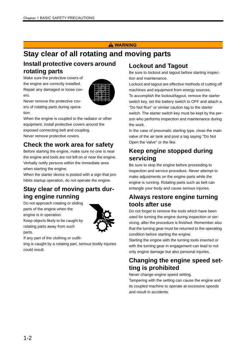
Stay clear of all rotating and moving partsInstall protective covers around rotating partsMake sure the protective covers of the engine are correctly installed. Repair any damaged or loose cov-ers.Never remove the protective cov-ers of rotating parts during opera-tion. When the engine is coupled to the radiator or other equipment, install protective covers around the exposed connecting belt and coupling.Never remove protective covers.
Check the work area for safetyBefore starting the engine, make sure no one is near the engine and tools are not left on or near the engine. Verbally notify persons within the immediate area when starting the engine.When the starter device is posted with a sign that pro-hibits startup operation, do not operate the engine.
Stay clear of moving parts dur-ing engine runningDo not approach rotating or sliding parts of the engine when the engine is in operation.Keep objects likely to be caught by rotating parts away from such parts.If any part of the clothing or outfit-ting is caught by a rotating part, serious bodily injuries could result.
Lockout and TagoutBe sure to lockout and tagout before starting inspec-tion and maintenance.Lockout and tagout are effective methods of cutting off machines and equipment from energy sources.To accomplish the lockout/tagout, remove the starter switch key, set the battery switch to OFF and attach a "Do Not Run" or similar caution tag to the starter switch. The starter switch key must be kept by the per-son who performs inspection and maintenance during the work.In the case of pneumatic starting type, close the main valve of the air tank and post a tag saying "Do Not Open the Valve" or the like.
Keep engine stopped during servicingBe sure to stop the engine before proceeding to inspection and service procedure. Never attempt to make adjustments on the engine parts while the engine is running. Rotating parts such as belt can entangle your body and cause serious injuries.
Always restore engine turning tools after useDo not forget to remove the tools which have been used for turning the engine during inspection or ser-vicing, after the procedure is finished. Remember also that the turning gear must be returned to the operating condition before starting the engine.Starting the engine with the turning tools inserted or with the turning gear in engagement can lead to not only engine damage but also personal injuries.
Changing the engine speed set-ting is prohibitedNever change engine speed setting.Tampering with the setting can cause the engine and its coupled machine to operate at excessive speeds and result in accidents.
1-2
Chapter 1 BASIC SAFETY PRECAUTIONS
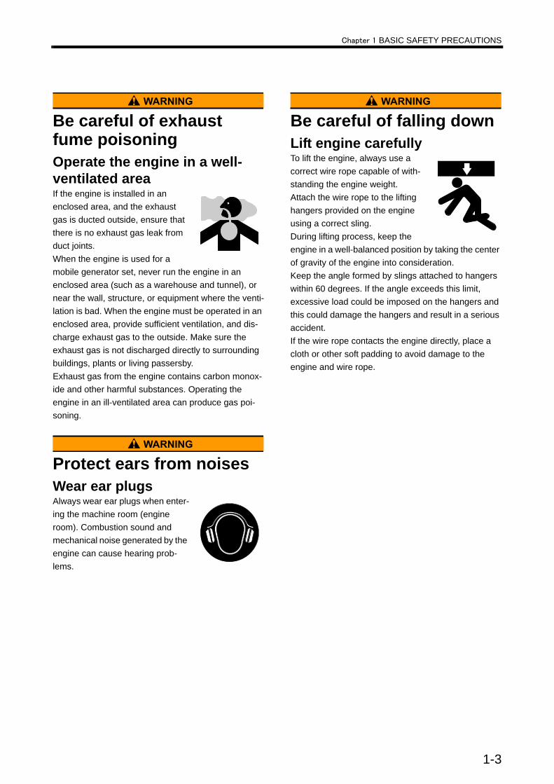
Be careful of exhaust fume poisoningOperate the engine in a well-ventilated areaIf the engine is installed in an enclosed area, and the exhaust gas is ducted outside, ensure that there is no exhaust gas leak from duct joints.When the engine is used for a mobile generator set, never run the engine in an enclosed area (such as a warehouse and tunnel), or near the wall, structure, or equipment where the venti-lation is bad. When the engine must be operated in an enclosed area, provide sufficient ventilation, and dis-charge exhaust gas to the outside. Make sure the exhaust gas is not discharged directly to surrounding buildings, plants or living passersby.Exhaust gas from the engine contains carbon monox-ide and other harmful substances. Operating the engine in an ill-ventilated area can produce gas poi-soning.
Protect ears from noisesWear ear plugsAlways wear ear plugs when enter-ing the machine room (engine room). Combustion sound and mechanical noise generated by the engine can cause hearing prob-lems.
Be careful of falling downLift engine carefullyTo lift the engine, always use a correct wire rope capable of with-standing the engine weight.Attach the wire rope to the lifting hangers provided on the engine using a correct sling.During lifting process, keep the engine in a well-balanced position by taking the center of gravity of the engine into consideration.Keep the angle formed by slings attached to hangers within 60 degrees. If the angle exceeds this limit, excessive load could be imposed on the hangers and this could damage the hangers and result in a serious accident.If the wire rope contacts the engine directly, place a cloth or other soft padding to avoid damage to the engine and wire rope.
1-3
Chapter 1 BASIC SAFETY PRECAUTIONS
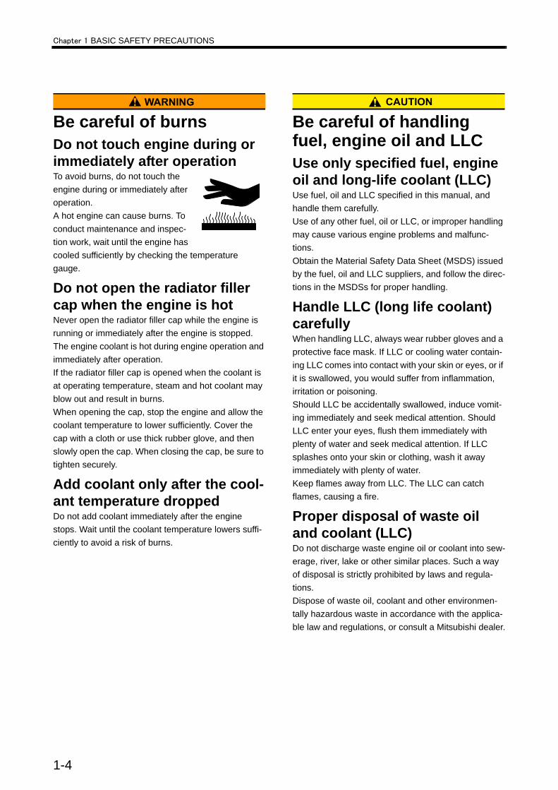
Be careful of burnsDo not touch engine during or immediately after operationTo avoid burns, do not touch the engine during or immediately after operation.A hot engine can cause burns. To conduct maintenance and inspec-tion work, wait until the engine has cooled sufficiently by checking the temperature gauge.
Do not open the radiator filler cap when the engine is hotNever open the radiator filler cap while the engine is running or immediately after the engine is stopped. The engine coolant is hot during engine operation and immediately after operation.If the radiator filler cap is opened when the coolant is at operating temperature, steam and hot coolant may blow out and result in burns.When opening the cap, stop the engine and allow the coolant temperature to lower sufficiently. Cover the cap with a cloth or use thick rubber glove, and then slowly open the cap. When closing the cap, be sure to tighten securely.
Add coolant only after the cool-ant temperature droppedDo not add coolant immediately after the engine stops. Wait until the coolant temperature lowers suffi-ciently to avoid a risk of burns.
Be careful of handling fuel, engine oil and LLCUse only specified fuel, engine oil and long-life coolant (LLC)Use fuel, oil and LLC specified in this manual, and handle them carefully.Use of any other fuel, oil or LLC, or improper handling may cause various engine problems and malfunc-tions.Obtain the Material Safety Data Sheet (MSDS) issued by the fuel, oil and LLC suppliers, and follow the direc-tions in the MSDSs for proper handling.
Handle LLC (long life coolant) carefullyWhen handling LLC, always wear rubber gloves and a protective face mask. If LLC or cooling water contain-ing LLC comes into contact with your skin or eyes, or if it is swallowed, you would suffer from inflammation, irritation or poisoning. Should LLC be accidentally swallowed, induce vomit-ing immediately and seek medical attention. Should LLC enter your eyes, flush them immediately with plenty of water and seek medical attention. If LLC splashes onto your skin or clothing, wash it away immediately with plenty of water.Keep flames away from LLC. The LLC can catch flames, causing a fire.
Proper disposal of waste oil and coolant (LLC)Do not discharge waste engine oil or coolant into sew-erage, river, lake or other similar places. Such a way of disposal is strictly prohibited by laws and regula-tions.Dispose of waste oil, coolant and other environmen-tally hazardous waste in accordance with the applica-ble law and regulations, or consult a Mitsubishi dealer.
1-4
Chapter 1 BASIC SAFETY PRECAUTIONS
Service batteryHandle the battery correctly• Never use flames or allow
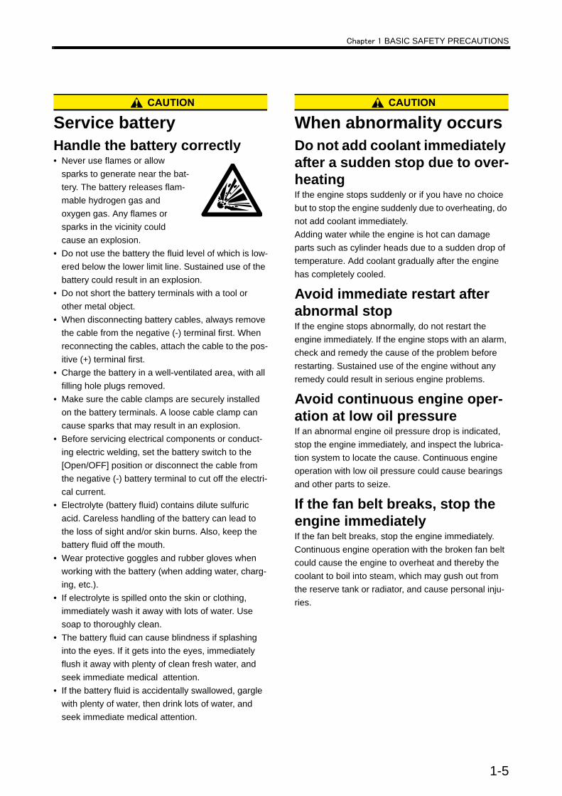
sparks to generate near the bat-tery. The battery releases flam-mable hydrogen gas and oxygen gas. Any flames or sparks in the vicinity could cause an explosion.
• Do not use the battery the fluid level of which is low-ered below the lower limit line. Sustained use of the battery could result in an explosion.
• Do not short the battery terminals with a tool or other metal object.
• When disconnecting battery cables, always remove the cable from the negative (-) terminal first. When reconnecting the cables, attach the cable to the pos-itive (+) terminal first.
• Charge the battery in a well-ventilated area, with all filling hole plugs removed.
• Make sure the cable clamps are securely installed on the battery terminals. A loose cable clamp can cause sparks that may result in an explosion.
• Before servicing electrical components or conduct-ing electric welding, set the battery switch to the [Open/OFF] position or disconnect the cable from the negative (-) battery terminal to cut off the electri-cal current.
• Electrolyte (battery fluid) contains dilute sulfuric acid. Careless handling of the battery can lead to the loss of sight and/or skin burns. Also, keep the battery fluid off the mouth.
• Wear protective goggles and rubber gloves when working with the battery (when adding water, charg-ing, etc.).
• If electrolyte is spilled onto the skin or clothing, immediately wash it away with lots of water. Use soap to thoroughly clean.
• The battery fluid can cause blindness if splashing into the eyes. If it gets into the eyes, immediately flush it away with plenty of clean fresh water, and seek immediate medical attention.
• If the battery fluid is accidentally swallowed, gargle with plenty of water, then drink lots of water, and seek immediate medical attention.
When abnormality occursDo not add coolant immediately after a sudden stop due to over-heatingIf the engine stops suddenly or if you have no choice but to stop the engine suddenly due to overheating, do not add coolant immediately.Adding water while the engine is hot can damage parts such as cylinder heads due to a sudden drop of temperature. Add coolant gradually after the engine has completely cooled.
Avoid immediate restart after abnormal stopIf the engine stops abnormally, do not restart the engine immediately. If the engine stops with an alarm, check and remedy the cause of the problem before restarting. Sustained use of the engine without any remedy could result in serious engine problems.
Avoid continuous engine oper-ation at low oil pressureIf an abnormal engine oil pressure drop is indicated, stop the engine immediately, and inspect the lubrica-tion system to locate the cause. Continuous engine operation with low oil pressure could cause bearings and other parts to seize.
If the fan belt breaks, stop the engine immediatelyIf the fan belt breaks, stop the engine immediately. Continuous engine operation with the broken fan belt could cause the engine to overheat and thereby the coolant to boil into steam, which may gush out from the reserve tank or radiator, and cause personal inju-ries.
1-5
Chapter 1 BASIC SAFETY PRECAUTIONS
Other cautionsNever modify engineUnauthorized modification of the engine will void the manufacturer's warranty.Modification of the engine may not only cause engine damage but also produce personal injuries.If there is a need to modify the engine, contact your Mitsubishi dealer.
Never break the sealsTo ensure proper engine operation, the fuel control links are sealed to prevent accidental change of the injection volume and rotation speed settings. Operat-ing the engine without these seals in place can cause the problems described below, and also invalidates the warranty.• Rapid wear of sliding and rotating parts• Engine damage such as seizing of engine parts• Considerably increased consumption of fuel and
lubricating oil• Degradation of engine performance due to improper
balance between fuel injection volume and governor operation or overrunning of the engine which could result in a serious accident.
Perform all specified pre-opera-tion inspections and periodic inspectionsConduct the pre-operation inspections and periodic inspections as described in this manual.Failure to conduct the specified inspections may cause various engine problems, damage to parts, and serious accidents.
Break-in the engineTo break in new engines or overhauled engines, oper-ate the engine at a speed lower than the rated speed in a light load condition during the first 50 hours of operation.Operating new engines or overhauled engines in a severe condition during the break-in period shortens the service life of the engine.
Warm up the engine before useWhen starting auxiliary devices, such as a water heater and an engine oil priming pump, are not installed, let the engine idle for 5 to 10 minutes before operating the engine for work. Warm-up operation cir-culates lubricants in the engine and contributes to a longer service life and economical operation. Do not conduct warm-up operation for prolonged period of time.Prolonged warm-up operation causes carbon build-up in the cylinders that leads to incomplete combustion.
Never operate the engine in an overloaded conditionIf the engine shows an overloaded condition such as black exhaust smoke, reduce the load immediately to operate the engine at an appropriate output and load. Overloading causes not only high fuel consumption but also excessive carbon deposits inside the engine. Carbon deposits cause various problems and will shorten the service life of the engine.
Conduct cooling operation before stopping the engineBefore stopping the engine, let it idle at low speed for 5 to 6 minutes to cool down.Stopping the engine immediately after high-load oper-ation will cause engine parts to heat up and shorten the service life of the engine.During cooling operation, check the engine for abnor-malities.
Protection of the engine against water entryDo not allow rainwater, etc. to enter the engine through the air inlet or exhaust openings.Do not wash the engine while it is operating. Cleaning fluid (water) can be sucked into the engine.Starting the engine with water inside the combustion chambers can cause the water hammer action which may result in internal engine damage and serious accidents.
1-6
Chapter 1 BASIC SAFETY PRECAUTIONS
Properly maintain the air cleaner and pre-cleanerThe major cause of abnormal wear on engine parts is dust from intake air. Worn parts produce many prob-lems such as an increase of oil consumption, decrease of output, and starting difficulties. For effec-tive removal of dust from intake air, maintain the air cleaner or pre-cleaner according to the following instructions.• Do not maintain the air cleaner/pre-cleaner while the
engine is operating. Operating the engine without the air cleaner/pre-cleaner allows foreign matters to enter the turbocharger and could result in serious damage.
• Remove the air cleaner/pre-cleaner slowly to pre-vent dust accumulated on the element from falling off. After removing the air cleaner or pre-cleaner, immediately cover the opening (inlet port of air cleaner; port in body for pre-cleaner) with plastic sheet or similar means to prevent dust from entering the engine.
• Air cleaners equipped with a dust indicator will issue an alarm if the element gets clogged. Service the cleaner as soon as possible if an alarm is issued.
Observe safety rules at work siteObserve the safety rules established at your work-place when operating and maintaining the engine.Do not operate the engine if you are feeling ill, inform your supervisor of your condition.Operation of the engine with reduced awareness may cause improper operation that could result in acci-dents.When working in a team fo two or more people, use specified hand signals to communicate among work-ers.
Work clothing and protective gearWear a hardhat, face shield, safety shoes, dust mask, gloves and other protective gear as needed.When handling compressed air, wear safety goggles, a hardhat, gloves and other necessary protective gear. Works without wearing proper protective gear could result in serious injuries.
Use of tools optimum for each workAlways keep in mind to select most appropriate tools for the work to be performed and use them correctly. If tools are damaged, replace them with new tools.
Do not operate the starter for a prolonged timeDo not operate the starter for more than 10 seconds at a time even if the engine does not start. Wait for at least 30 seconds before next engine cranking.Continuous operation of the starter will drain the bat-tery power and cause seizing of the starter.
Do not turn off the battery switch during operationIf the battery switch is turned OFF when the engine is running, not only various meters will stop working but also the alternator may have its diode and transistor deteriorated.
Cautionary instructions for transporting the engineWhen transporting the engine on a truck, consider the engine weight, width and height to ensure safety. Abide by road traffic law, road vehicles act, vehicle restriction ordinance and other pertinent laws.
Do not touch high-pressure injection fuelIf fuel leaks or sprays out from the high pressure injec-tion pipe, do not touch the fuel.Fuel in the fuel injection pipes is under high pressure and if the fuel contact your skin, it goes into deep tis-sues and may result in gangrene.
1-7

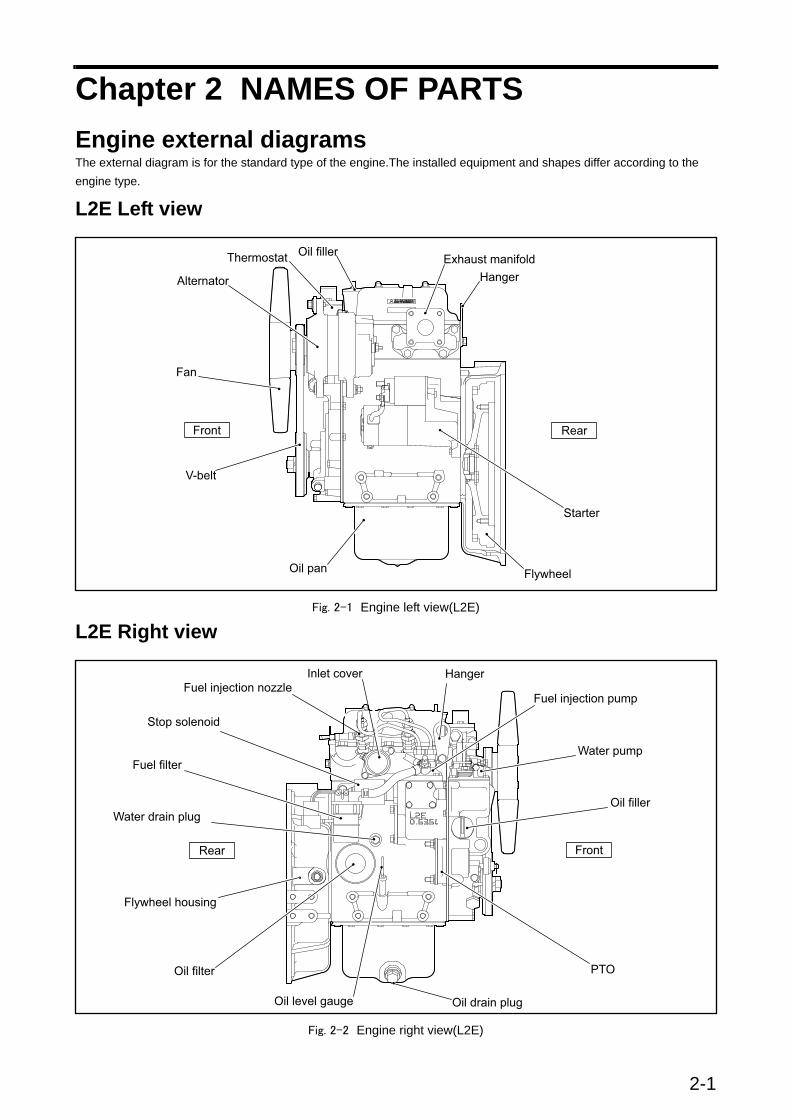
Chapter 2 NAMES OF PARTSEngine external diagramsThe external diagram is for the standard type of the engine.The installed equipment and shapes differ according to the engine type.
L2E Left view
Fig. 2-1 Engine left view(L2E)
L2E Right view
Fig. 2-2 Engine right view(L2E)
2-1

Chapter 2 NAME OF PARTS
L3C,L3E Left view
Fig. 2-3 Engine left view(L3C,L3E)
L3C,L3E Right view
Fig. 2-4 Engine right view(L3C,L3E)
2-2

Chapter 2 NAMES OF PARTS
Equipment and instrumentDescribed below is for standard equipment of this engine. The installed equipment and shapes differ on the engine type.
Starter switchThe starter switch is used to start the engine.HEATWhen the key is turned to this position, the glow plugs become hot and allow easy startup of a cold engine.OFFWhen the key is turned to this position, power supply to the electric circuits is cut off, and the key can be removed and inserted at this position. To stop the engine, turn the key to this position.ONWhen the key is at this position, power is supplied to the electric circuits. After the engine starts, the key is set to this position.STARTWhen the key is turned to this position, the starter cranks the engine and the engine starts. When the key is released, it automatically returns to the [ON] position.
Fig. 2-5 Starter switch
Preheat indicatorThe condition of preheating glow plug is indicated by the preheating indicator.
Automatic glow typeA preheat light glows when glow timer turns on, and the light is turned off when the preheating is com-pleted.
Manual glow typeWhen the temperature of the preheating glow plug is increased, the glow signal turns red when the preheat-ing is completed. Fig. 2-6 Preheat indicator
Water temperature meter and thermo unitThe engine coolant temperature detected by the thermo unit is displayed by the water temperature meter. If the coolant temperature becomes 95°C [203°F] or higher, operate the engine at low idling speed for cooling down and after the engine becomes cool, check the cooling system.
Fig. 2-7 Water temperature meter and thermo unit
2-3

Chapter 2 NAMES OF PARTS
AmmeterThe ammeter shows the charging condition of battery when the engine is running. The indicator needle swings to the positive ( + ) side when battery is charged and to the negative (-) side when the battery is discharged.
Fig. 2-8 Ammeter
Hour meterHours of operation is displayed.Conduct the maintenance service based on the oper-ating hours displayed on this meter.
Fig. 2-9 Hour meter
Stop solenoidA stop solenoid is installed to stop the engine in the regular operation.The stop solenoid moves the rack of fuel injection pump to cut the fuel, and consequently stops the engine.Two types of stop solenoids are available.
RUN OFF (ETS: Energized To Stop) TypeNot energized while the engine is running. Energized by a stop signal to stop the engine.
RUN ON (ETR: Energized To Run) TypeEnergized while the engine is running, and de-ener-gized to stop the engine.
Fig. 2-10 Stop solenoid
2-4
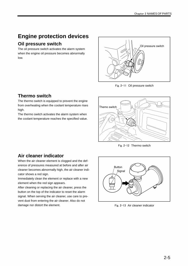
Chapter 2 NAMES OF PARTS
Engine protection devicesOil pressure switchThe oil pressure switch activates the alarm system when the engine oil pressure becomes abnormally low.
Fig. 2-11 Oil pressure switch
Thermo switchThe thermo switch is equipped to prevent the engine from overheating when the coolant temperature rises high. The thermo switch activates the alarm system when the coolant temperature reaches the specified value.
Fig. 2-12 Thermo switch
Air cleaner indicatorWhen the air cleaner element is clogged and the def-erence of pressures measured at before and after air cleaner becomes abnormally high, the air cleaner indi-cator shows a red sign.Immediately clean the element or replace with a new element when the red sign appears.After cleaning or replacing the air cleaner, press the button on the top of the indicator to reset the alarm signal. When serving the air cleaner, use care to pre-vent dust from entering the air cleaner. Also do not damage nor distort the element. Fig. 2-13 Air cleaner indicator
2-5


Chapter 3 OPERATIONPreparations for operation
Should an engine abnormality be observed during operation, stop the engine and correct the problem, or contact a Mitsubishi dealer.
Always conduct the following inspection before starting the engine.
External inspection
Be sure to keep combustible materials away from the engine, especially from the hot engine parts such as exhaust manifolds, or the battery. Check for fuel and oil leaks. Clean the top of the battery with a wet cloth before starting the engine, as dust on the battery can easily ignite. If any abnormality is found, be sure to repair it or contact your Mit-subishi dealer.
Inspect the engine exterior as described below.1. Make sure there is no combustible material near the engine or battery. Also, check to make sure that the engine
and battery are clean. If combustible materials or dust are found near the engine or battery, remove them.2. Check the electrical wiring for such components as the starter and alternator for looseness.3. Check the entire engine for leaks of fuel, engine oil or coolant. If a leak is found, repair the leak, or contact your
Mitsubishi dealer.4. Make sure the following valves, plugs and cocks are open or closed properly:・ Fuel feed valve: Open・ Coolant drain cock (plug): Closed・ Oil drain valve: Closed
Inspecting the battery electrolyte level
If battery electrolyte is spilled on your skin, flush immediately with plenty of water. If battery electrolyte enters the eyes, flush them immediately with lots of fresh water and seek medical attention at once. Do not use open flames or other fire hazards near the battery. When handling the battery, be careful of sparks generated by accidental short-ing. For other cautions in handling the battery, refer to "Service battery" (1-5).
Battery electrolyte evaporates during use and the fluid level gradually decreases. The correct fluid surface level is between the LOWER LEVEL and UPPER LEVEL lines. For the battery without level lines, the correct fluid surface level is about 10 to 15 mm [0.394 to 0.591 in.] above the top of the plates. If the fluid level is low, remove the caps and add distilled water to the proper level.Note: When adding distilled water, pour in carefully.
Fig. 3-1 Checking battery electrolyte level
3-1
Chapter 3 OPERATION
Checking the fuel tank oil level
When working around fuel, make sure there are no open flames, heaters or other fire hazards. Wipe off any spilled fuel completely. Spilled fuel can ignite and cause a fire.
Do not remove the strainer when filling the fuel tank. For fuel to be used, refer to "FUEL" (4-1).
Make sure the fuel tank is full. If the fuel level is low, refill the tank to the “FULL” level.
Fig. 3-2 Checking fuel level
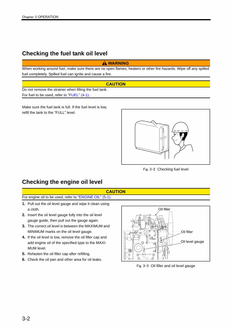
Checking the engine oil level
For engine oil to be used, refer to "ENGINE OIL" (5-1).
1. Pull out the oil level gauge and wipe it clean using a cloth.
2. Insert the oil level gauge fully into the oil level gauge guide, then pull out the gauge again.
3. The correct oil level is between the MAXIMUM and MINIMUM marks on the oil level gauge.
4. If the oil level is low, remove the oil filler cap and add engine oil of the specified type to the MAXI-MUM level.
5. Refasten the oil filler cap after refilling.6. Check the oil pan and other area for oil leaks.
Fig. 3-3 Oil filler and oil level gauge
3-2

Chapter 3 OPERATION
Checking the coolant level
Remove the radiator cap only after the engine has cooled to room temperature. Place a cloth over the cap, and loosen the cap about a half-turn or stand the lever to the upright position to release internal pres-sure. Opening the radiator cap while the engine is hot causes steam and hot coolant to spray out and may result in skin burns.
1. Open the radiator cap and check the coolant level.2. If the coolant level is low, add coolant to the speci-
fied level.
Always use the coolant with the same LLC concentra-tion.
Note: Determine the quantities of LLC based on the coolant capacity and the LLC concentration chart.For the coolant, refer to "COOLANT" (6-1). For the coolant capacity, refer to "MAIN SPECIFI-CATIONS" (12-1).
3. If a reserve tank is equipped, fill the reserve tank with coolant up to the [FULL] line level.
Fig. 3-4 Radiator cap
Fig. 3-5 Radiator coolant level
Fig. 3-6 Reserve tank coolant level
3-3

Chapter 3 OPERATION
StartingThe starting method changes based on the application and specifications. Start the engine according to the specified procedure.
Before starting the engine, check to make sure no one is near the engine and that tools are not left on or near the engine. In a loud voice, notify people in the area when starting the engine.
Do not apply a load to the engine at starting.(Disen-gage the clutch if installed.)A long and continuous operation of the starter drains the battery power, and it can also burn the starter.Do not use the starter for more than 10 seconds at a time. When the engine does not start, wait for more than 30 seconds before cranking again.When pre-heating, do not preheat the eninge for more than one minute each time (for manual glow plug). Pre-heating longer than one minute will not only cause premature battery decrease, but also shorten glow plug life.
Automatic grow plug1. Turn the starter key to "ON" position.
And make sure that oil pressure, water tempera-ture and pre-heating lamps are lit. Pre-heating lamp lighted duration is as follows:
2. When pre-heating lamp goes out, turn the starter key to "START" position to start the engine.Note that pre-heating lamp will be lit with the starter key in the "START" position.
3. When the engine is started, let go of the key. The key will automatically return to the "ON" (opera-tion) position.
Manual grow plug1. Turn the starter key to "HEAT" position.
Pre-heating duration is as follows:
2. When pre-heating indicator glows , turn the starter key to "START" position to start the engine.
3. When the engine is started, let go of the key. The key will automatically return to the "ON" (opera-tion) position.
Table 3-1 Pre-heating duration (automatic grow plug)
Specifications Water temperature Pre-heat-ing duration
Quick type
Low water temper-ature (5°C [41°F] or below)
Approx. 3 seconds
High water temper-ature (5°C [41°F] or above)
Approx. 1 seconds
Standard type Any timeApprox. 6 or 10 sec-
onds
Table 3-2 Pre-heating duration (manual grow plug)Temperature Pre-heating duration
+5°C [41°F] or above Approx. 10 seconds-5°C [23°F] or above, below +5°C [41°F] Approx. 20 seconds
Below -5°C [23°F] Approx. 30 seconds
3-4

Chapter 3 OPERATION
Warming-up operation
Do not approach rotating parts during operation. Entanglement by rotating parts can cause serious injury.
Do not conduct warm-up operation for a prolonged period of time. Prolonged warm-up operation causes carbon buildup in the cylinders that leads to incomplete combustion.Do not turn the battery switch to OFF. Turning off the battery switch while the engine is in warm-up opera-tion not only stops the instrument operations but also may deteriorate the alternator diode and regulator.Never turn the key to the START position during warm-up operation, as it damages starter. During warming-up operation, do not operate the engine in an overloaded condition (if overloaded, black smoke is exhausted). Operating the engine in an overloaded condition not only increases fuel con-sumption but also generates excessive carbon depos-its inside the engine which considerably shortens the service life of the engine.
After the engine starts, operate the engine in a no load condition at low idling speed for 5 to 10 minutes to warm up the engine.
Checking engine oil pressureDuring warming-up operation, check if the oil pressure is in the range of standard value.Also, make sure the oil pressure gauge is operating properly.Note: The oil pressure gauge may indicate a higher
level than normal level immediately after the engine starts, due to the low oil temperature. The pressure gradually lowers to the normal level as the oil temperature rises.
External inspection during warm-upVisually check the external view of the engine for leaks of fuel, engine oil and coolant, or leaks of exhaust gas from joints.
3-5

Chapter 3 OPERATION
Operation
Do not approach rotating parts during operation. Entanglement by rotating parts can cause serious injury.
Do not touch any hot part of the engine such as exhaust pipes during operation or immediately after shut down. A hot engine can cause burns.
Always provide adequate ventilation in the engine room. If air supply to the engine room is not sufficient, the room temperature rises and can affect engine out-put and performance. For the first 50 hours, operate the engine under a light load for break-in operation. Operating the engine under heavy load or severe con-ditions during the break-in period can shorten the ser-vice life of the engine. Do not turn the battery switch to OFF when the engine is in operation. Turning off the battery switch during operation not only stops the battery charge but also causes malfunctioning of instruments and deteriorates the alternator diode and regulator. Never turn the key to the START position during oper-ation. The starter may be damaged.
Inspection during operationCarefully check the exterior of engine such as piping joints for leaks.Check for abnormal engine noises or vibrations such as knocking.Check the color of exhaust gas from the exhaust muf-fler. Note: For abnormal exhaust gas conditions, refer to
"Other problems and countermeasures" (11-3).Check the instruments and gauges for proper opera-tion and make sure they indicates normal values.
Note :(a) When the oil pressure drops below 0.15 MPa {1.5 kgf/cm²} [21 psi] in normal opera-tion, or below 0.05 MPa {0.5 kgf/cm²} [7 psi] at low idling, stop the engine immediately. Be sure to locate the cause of problem and correct it before restarting the engine.
(b) When the high temperature alarm switch is activated in normal operation, change the engine operation immediately to low idling operation until the engine temperature decreases to the normal operating level. Then, operate the engine for another 5 or 6 minutes for cooling before stopping the engine. Be sure to locate the cause of prob-lem and correct it before restarting the engine.
Table 3-3 Standard values at rated speed
Item Standard value
Engine oil pressure gauge
0.29 to 0.49 MPa{3 to 5 kgf/cm²} [43 to 71 psi]
Coolant temperature 70 to 90°C[158 to 194 °F]
3-6

Chapter 3 OPERATION
Stopping
Stopping the engine suddenly during high speed operation creates a local abnormal high temperature rise, and shortens the service life of engine. Except in an emergency, be sure to conduct the cooling operation for 5 to 6 min-utes at low idling speed before stopping the engine. During the cooling operation, check the engine for abnormali-ties. Never accelerate the engine immediately before shutting it down. Do not restart the engine immediately after abnormal shut down. When the engine stops with alarms, be sure to locate the cause of the problem and correct the problem before restarting the engine. After restarting the operation, check the engine for abnormalities again. If abnormalities still exist, contact your Mitsubishi dealer.
Engine stopping method changes depending on the specifications.Follow the instructions according to the specifi-cations of the equipment.
Inspection after stoppingInspect the engine for leaks of fuel, oil or coolant. If any leak is found, repair the leak or contact your Mitsubishi dealer.
3-7

4-1
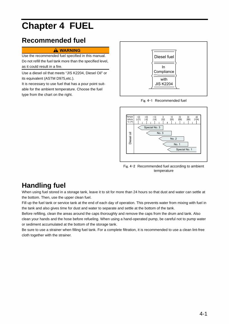
Chapter 4 FUELRecommended fuel
Use the recommended fuel specified in this manual. Do not refill the fuel tank more than the specified level, as it could result in a fire.
Use a diesel oil that meets “JIS K2204, Diesel Oil” or its equivalent (ASTM D975,etc.).It is necessary to use fuel that has a pour point suit-able for the ambient temperature. Choose the fuel type from the chart on the right.
Fig. 4-1 Recommended fuel
Fig. 4-2 Recommended fuel according to ambient temperature
Handling fuelWhen using fuel stored in a storage tank, leave it to sit for more than 24 hours so that dust and water can settle at the bottom. Then, use the upper clean fuel.Fill up the fuel tank or service tank at the end of each day of operation. This prevents water from mixing with fuel in the tank and also gives time for dust and water to separate and settle at the bottom of the tank.Before refilling, clean the areas around the caps thoroughly and remove the caps from the drum and tank. Also clean your hands and the hose before refueling. When using a hand-operated pump, be careful not to pump water or sediment accumulated at the bottom of the storage tank.Be sure to use a strainer when filling fuel tank. For a complete filtration, it is recommended to use a clean lint-free cloth together with the strainer.

Chapter 5 ENGINE OILProperties of engine oil and its influence on engine performanceEngine oil lubricates the engine and greatly influences the performance and durability of the engine.Distinctive differences of engine oil from other oils are that engine oil lubricates hot sections adjacent to the combustion chamber and is strongly affected by the combustion products. Engine oils, therefore, are required to have cooling, sealing, deterging, and neu-tralizing abilities in addition to the lubricating function.Because diesel engines especially produce acid prod-ucts such as sulfuric acid due to the sulfur content of the fuel and soot due to imperfect combustion that contaminates oils, engine oils for diesel engines must have capabilities not only to withstand severe lubricat-ing conditions, but also to neutralize acid products to prevent them from agglomerating and depositing.The function of performance required for engine oils is shown below:• Good detergent dispersability for high temperature
applications, for preventing contamination and dep-osition of sludge and soot.
• Excellent acid neutralizing capability to inhibit oxi-dization due to sulfur content of fuel.
• Good oxidation stability that withstands long hours at high temperature.
• Appropriate viscosity to maintain lubricity and low-temperature startability.
• Good rust and corrosion resistance to water.• Good foam resistance to prevent the lubricating
quality from lowering due to oxidation.
Main properties of engine oilDispersibilityEngine oil performance degrades through oxidation and also by external causes. Acid products such as sulfuric acid due to sulfur content of fuel become insol-uble sludge. Incomplete combustion of fuel creates soot in oil.This sludge and soot in oil are accumulated in the groove or on the inner surface of piston rings and will result in seizure or wear of the piston rings, or it will lower heat transfer of the piston rings drastically. Dis-persibility of engine oil is to disperse sludge and soot in oil in order to prevent it from depositing.
Acid neutralization abilityCompared to gasoline fuel, diesel oil produces more sulfuric acid due to the high sulfur content in the fuel during combustion, and the sulfuric acid contaminates the oil. To neutralize the sulfuric acid, engine oils are required to have excellent neutralizing ability. Engine oils for diesel engines usually contain a detergent metal agent that has high neutralization ability.
ViscosityOils flow with difficulty at lower temperatures, and flow smoothly at high temperatures. The oil viscosity is a property that indicates resistance to flow. This prop-erty of viscosity directly relates to low-temperature startability, lubricity, fuel consumption by friction loss, and oil consumption.For identification of an oil's viscosity, SAE (Society of Automotive Engineers) numbers are widely used. (The viscosity of engine oil identified by the number of SAE shows the thickness or thinness of viscosity at particular temperature.)The property of engine oils is identified not only by vis-cosity number that shows thickness and thinness of viscosity at particular temperature, but also by viscos-ity index that shows the changes in oil viscosity with changes in temperature. When the viscosity index of oil is high, it means the change of viscosity due to temperature is small. The viscosity index (VI)-100 of oil is generally applied to diesel engine oil. Oils indicated by, for instance, VI-100 are called single grade oil, which fall under one range of viscosity. There are also oils called "multi-grade oil" for which viscosity falls under two ranges of viscosity and they are indicated by, for instance, SAE 15W-40, which means that at a lower temperature, the oil has 15W grade, and at a higher temperature it has a 40W grade. ("W" indicates the suitability of oil for colder temperature). In other words, 15W-40 indicated on oil demonstrates SAW15 grade of viscosity at a lower temperature and 40 grade viscosity at a higher temperature.
5-1
Chapter 5 ENGINE OIL
Recommended engine oil
Use only the engine oils recommended in this manual. Never use other oils. The use of inappropriate or inferior oils will result in sticking of piston rings, seizure between piston and cylinder, or premature wear of bearings and moving parts, and significantly shortens the service life of the engine.
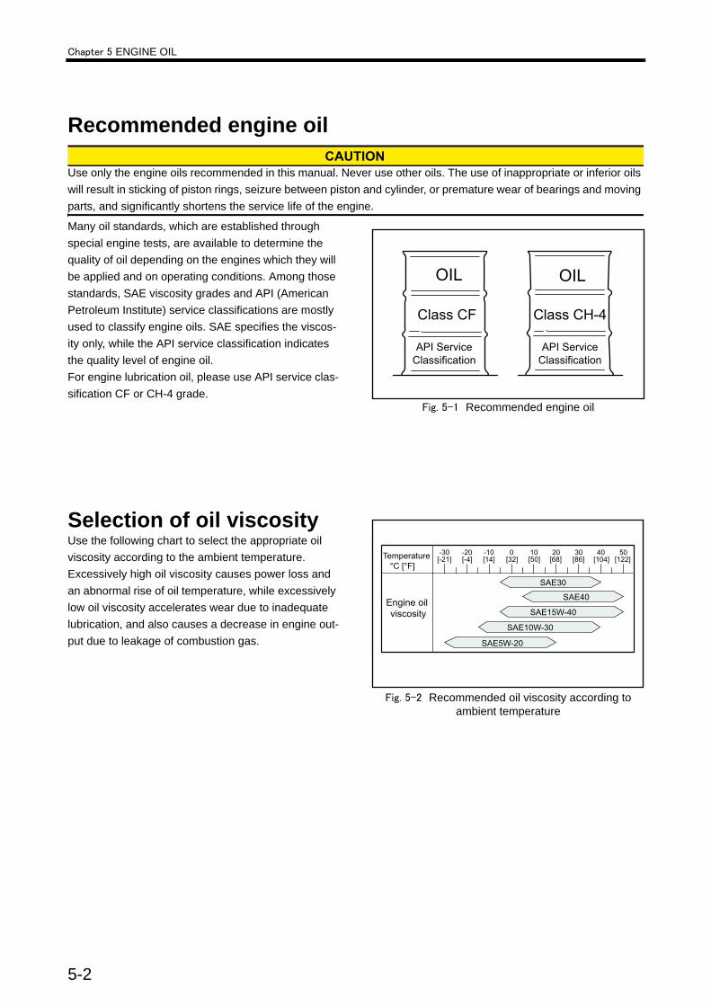
Many oil standards, which are established through special engine tests, are available to determine the quality of oil depending on the engines which they will be applied and on operating conditions. Among those standards, SAE viscosity grades and API (American Petroleum Institute) service classifications are mostly used to classify engine oils. SAE specifies the viscos-ity only, while the API service classification indicates the quality level of engine oil.For engine lubrication oil, please use API service clas-sification CF or CH-4 grade.
Fig. 5-1 Recommended engine oil
Selection of oil viscosityUse the following chart to select the appropriate oil viscosity according to the ambient temperature.Excessively high oil viscosity causes power loss and an abnormal rise of oil temperature, while excessively low oil viscosity accelerates wear due to inadequate lubrication, and also causes a decrease in engine out-put due to leakage of combustion gas.
Fig. 5-2 Recommended oil viscosity according to ambient temperature
5-2
Chapter 5 ENGINE OIL
Other brands of engine oilThe quality and performance of commercially available oils as well as their components variations are the responsi-bility of engine oil suppliers. Before purchasing commercial oils, be sure to discuss the suitability of the engine oil with the oil supplier.
Handling engine oil
Before filling the engine with engine oil, stop the engine and make sure there are no open flames and other fire haz-ards near the engine. Leaked or spilled oil on hot surfaces or electrical components can cause a fire. Wipe off any spilled oil immediately and thoroughly. After filling, securely close the filler cap.
Never mix different brands of engine oil. Mixing different brands of engine oil may cause a chemical reaction of additives in the engine oil that could degrade the engine oil quality.
When handling oil in greater than the legally specified quantities, be sure to have the work performed by a service station in compliance with the law.When removing oil from the engine or oil can, use an oil pump. Do not suck oil with the mouth to siphon it.Be sure to close the cap on the oil can after use.Keep oil in a well-ventilated place and out of direct sunlight.Be sure to obtain the MSDS (material safety data sheet) of the engine oil used and follow the instructions of the MSDS.
5-3
Chapter 5 ENGINE OIL
Service limits of engine oilEngine oil degrades through the use and by lapse of time.Be sure to renew the engine oil if any of the properties below exceeds the limit.
Definition of properties of engine oilViscosityViscosity is a basic physical property of engine oil and is considered as the most important aspect when eval-uating oil.Contamination of oil by blow-by gas and deterioration of oil by its natural aging degrade the performance of viscosity, which will cause the deposition of sludge inside the engine and oil filter clogging. Contamination of oil by fuel and sheared molecules of viscosity index improver in oil also degrade the performance of vis-cosity, which will cause insufficient lubrication and fric-tion/wear of engine parts.
Total base numberTotal base number (TBN) shows the ability to neutral-ize acids such as organic acid due to engine oil oxida-tion, or sulfurous or sulfuric acid due to the sulfur content of fuel.Because TBN indicates the amount of dispersant detergent in oil, it can be used to estimate consump-tion of basic dispersant detergent. The ability to dis-perse sludge declines as dispersant detergent is used up.
Total acid numberThe total acid number in oil increases as the organic acid is being derived by the engine oil oxidation, or sulfurous acid or sulfuric acid derived by the combus-tion of sulfur content of fuel, or the oil becomes con-taminated with imperfect combustion products. An
increase in the total acid number will result in corro-sion or wear of the inner parts of the engine (such as cylinder liners or metal) due to sulfur content, and pis-ton ring seizure due to sludge.
WaterWater in oil promotes corrosion/wear, and decreases lubricity in sliding parts.
Flash pointThe flash point is lowered by contamination with fuels. Flash point is measured to check the dilution of fuel.The dilution of fuel reduces oil film, and causes insuffi-cient lubrication that will cause friction or wear of engine parts.
InsolublesInsolubles include acid products of engine oil, imper-fect combustion products, sludge or soot, metal abra-sive particles and dust. Insolubles are an indication of degradation/contamination of oil. Dispersant detergent, which is an additive in engine oil, absorbs sludge particles, and disperses them as fine particles in oil. Total insolubles density and remaining dispersibility can be obtained by measuring insolubles and coagu-lated insolubles (using chemical specialities to stop action of disperse detergent and to collect the sludge dispersed in oil) by which piston ring seizure or pre-mature wear can be prevented before it occurs.
Table 5-1 Service limit for engine oil propertiesProperty Service limit Test Method
Viscosity cst@100°C [212 °F] Within +30 and -15% of new oil JIS K2283
Total base number mgKOH/g 2.0 or more with hydrochloric acid (HCL) method1/2 of new oil or more with perchloric acid (PCA) method JIS K2501
Total acid number mgKOH/g Up to +3.0 of new oil JIS K2501
Water content Vol % 0.2 or less JIS K2275
Flash point (open cup) °C [°F] 180 [356] or more JIK K2265
Pentane insolubles Wt % 0.5 or less Comply withASTM D893
Pentane insolublescoagulated Wt % 3.0 or less Comply with
ASTM D893
5-4

Chapter 6 COOLANTNote: In this operation manual, the word "coolant" represents the liquid combined water and LLC.
Recommended water for coolantUse soft water for the engine cooling system. The water quality must meet the requirements in the Table below. Basically, the water quality should be within the recommended value, however, up to the limit is acceptable.
Note: Figures in parentheses are the standard value. In addition to the items specified above, turbidity is specified to be below 15 mg/liter.
Long life coolant (LLC)
Should coolant or LLC be accidentally swallowed, induce vomiting immediately and seek medical attention. If LLC should enter eyes, flush immediately with plenty of water and seek medical attention.
Be sure to use Mitsubishi genuine long life coolant (LLC) “GLASSY long life coolant (Ethylene glycol type)” or “PG GLASSY long life coolant (Non-amine type)” as coolant. When using other brand LLCs by necessity, be sure to use the LLC that meets the Mitsubishi specification. Mitsubishi heavy industries, Ltd. disclaim the warranty calim con-cerning mulfunctions caused by the use of LLC that does not meet the Mitsubishi specification.
Genuine LLCMitsubishi Heavy Industries, Ltd. recommends the use of our genuine long life coolant “GLASSY long life coolant (Ethylene glycol type)”, and Eco-friendly prod-uct “PG GLASSY long life coolant (Non-amine type)”, which are most appropriate coolant for Mitsubishi die-sel engine.
Fig. 6-1 GLASSY - LLC
Table 6-1 Water quality standards
Item Chemical symbol Unit Recommended Limit
Main adverse effect
Corrosion and rust
Scale formation
pH (25°C [77°F]) - - 6.5 to 8.0 6.5 to 8.5 ○ ○
Electrical conductivity (25°C [77°F]) - mS/m <25 <40 ○ ○
Total hardness CaCO3 ppm <95 <100 - ○
M alkalinity CaCO3 ppm <70 <150 - ○
Chlorine ion Cl- ppm <100 <100 ○ -
Sulfuric acid ion SO 2 4- ppm <50 <100 ○ -
Total iron Fe ppm <1.0 <1.0 - ○
Silica SiO2 ppm - <50 - ○
Residue from evaporation - ppm <250 <400 - ○
6-1
Chapter 6 COOLANT
Other brand LLCs
Never mix genuine Mitsubishi LLC with other brand LLCs. Mixing with other brand LLCs degrades the per-formance of the genuine Mitsubishi LLC.
When using LLC other than Mitsubishi genuine long life coolant (LLC) “GLASSY long life coolant (Ethylene glycol type)” or “PG GLASSY long life coolant (Non-amine type)”, be sure to use the LLC which meets Mit-subishi specification.The quality and performance of commercially avail-able LLCs as well as their component variations are the responsibility of LLC suppliers.Before purchasing commercial LLC, be sure to dis-cuss the suitability of LLC with the LLC supplier.Use only all-season LLC (non-amine type). Do not use antifreeze alone instead of LLC.
Standard for other brand LLCWhen using other brand LLCs by necessity, be sure to use the LLC that meets following specification. Mit-subishi heavy industries, Ltd. disclaim the warranty calim concerning mulfunctions caused by the use of LLC that does not meet the following specification.
General demands of LLC・ LLC shall be a homogeneous liquid.・ Engine cooling system shall not receive troubles
such as corrosions and precipitation products etc. by LLC when the LLC is diluted to 30 to 60% den-sity.
・ LLC shall be mixed with other LLC that satisfies this specification, and shall not separate elements each other, and shall not decrease the performance each other.
・ LLC shall not allow the container to be corroded, and shall not has precipitation products etc. even if LLC is left in the container for six months.
・ LLC shall not has extraction products etc. even if LLC is kept in -20 to -25°C [-4 to -13°F]
・ The validity term of the quality that provides with this specification is 2 years after it delivers with the indoor normal temperature keeping.
6-2

Chapter 6 COOLANT
LLC specificationLLC shall examine according to JIS K2234 section 7 (examination methods), and satisfy this specification. General matters and the sample to the examination is shown in JIS K2234.
Table 6-2 LLC specificationProperty Limit
External Not precipitation
Density Minimum 1.112 g/cm3(20/20°C)[68/68°F] (Stock solution)
Moisture Maximum 5.0 vol % (Stock solution)
Frozen temperature30 vol % Maximum -14.5°C[6°F]
50 vol % Maximum -34.0°C[29°F]
Boiling temperature Minimum 155°C[311°F] (Stock solution)
pH 7.0 to 11.0 (30 vol %)
Bubbling character(ASTM D3306-01)
30 vol % Maximum 4.0 ml
331/3 vol % Maximum 150 ml, Disappearance of bub-ble within 5sec.
Hard water adaptability Maximum 1.0 (50 vol %)
Metalic causticity (88 ± 2°C[187 to 194°F]、336 ± 2Hr、 30 vol % (E.G), 50 vol % (P.G)
Test Piece
Mass change
Aluminum ±0.30 mg/cm2
Cast iron ±0.15 mg/cm2
Steel ±0.15 mg/cm2
Brass ±0.15 mg/cm2
Solder ±0.30 mg/cm2
Copper ±0.15 mg/cm2
External of test piece after the examination
Not corrosion on surface excluding between test piece and spacer. Discolora-tion is OK.
Bubbling while examination Not bubbling overflow
Properties of liquid after the examination
pH 6.5 to 11.0
pH change ±1.0
Precipitation Maximum 0.5 vol %
External of liquid Not remarkable discoloration, separation and gel.
6-3
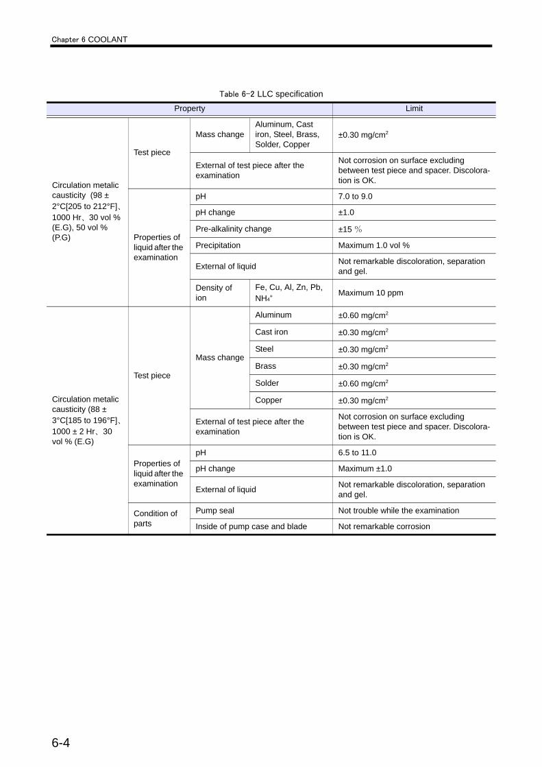
Chapter 6 COOLANT
Circulation metalic causticity (98 ± 2°C[205 to 212°F]、1000 Hr、30 vol % (E.G), 50 vol % (P.G)
Test piece
Mass changeAluminum, Cast iron, Steel, Brass, Solder, Copper
±0.30 mg/cm2
External of test piece after the examination
Not corrosion on surface excluding between test piece and spacer. Discolora-tion is OK.
Properties of liquid after the examination
pH 7.0 to 9.0
pH change ±1.0
Pre-alkalinity change ±15 %
Precipitation Maximum 1.0 vol %
External of liquid Not remarkable discoloration, separation and gel.
Density of ion
Fe, Cu, Al, Zn, Pb, NH4
+ Maximum 10 ppm
Circulation metalic causticity (88 ± 3°C[185 to 196°F]、1000 ± 2 Hr、30 vol % (E.G)
Test piece
Mass change
Aluminum ±0.60 mg/cm2
Cast iron ±0.30 mg/cm2
Steel ±0.30 mg/cm2
Brass ±0.30 mg/cm2
Solder ±0.60 mg/cm2
Copper ±0.30 mg/cm2
External of test piece after the examination
Not corrosion on surface excluding between test piece and spacer. Discolora-tion is OK.
Properties of liquid after the examination
pH 6.5 to 11.0
pH change Maximum ±1.0
External of liquid Not remarkable discoloration, separation and gel.
Condition of parts
Pump seal Not trouble while the examination
Inside of pump case and blade Not remarkable corrosion
Table 6-2 LLC specificationProperty Limit
6-4
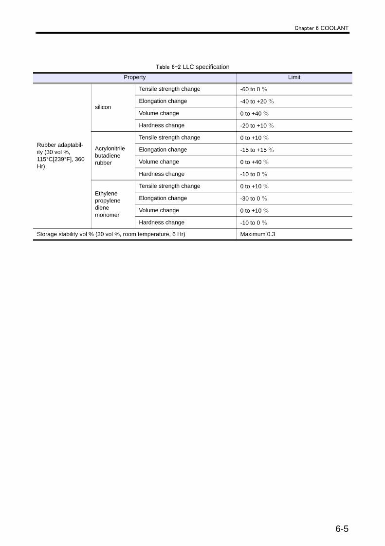
Chapter 6 COOLANT
Rubber adaptabil-ity (30 vol %, 115°C[239°F], 360 Hr)
silicon
Tensile strength change -60 to 0 %
Elongation change -40 to +20 %
Volume change 0 to +40 %
Hardness change -20 to +10 %
Acrylonitrilebutadiene rubber
Tensile strength change 0 to +10 %
Elongation change -15 to +15 %
Volume change 0 to +40 %
Hardness change -10 to 0 %
Ethylenepropylene diene monomer
Tensile strength change 0 to +10 %
Elongation change -30 to 0 %
Volume change 0 to +10 %
Hardness change -10 to 0 %
Storage stability vol % (30 vol %, room temperature, 6 Hr) Maximum 0.3
Table 6-2 LLC specificationProperty Limit
6-5
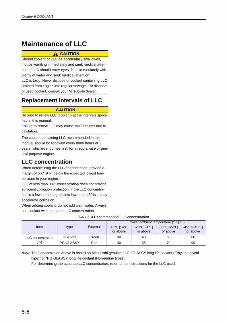
Chapter 6 COOLANT
Maintenance of LLC
Should coolant or LLC be accidentally swallowed, induce vomiting immediately and seek medical atten-tion. If LLC should enter eyes, flush immediately with plenty of water and seek medical attention.LLC is toxic. Never dispose of coolant containing LLC drained from engine into regular sewage. For disposal of used coolant, consult your Mitsubishi dealer.
Replacement intervals of LLC
Be sure to renew LLC (coolant) at the intervals speci-fied in this manual.Failure to renew LLC may cause malfunctions due to cavitation.
The coolant containing LLC recommended in this manual should be renewed every 8000 hours or 2 years, whichever comes first, for a regular-use or gen-eral-purpose engine.
LLC concentrationWhen determining the LLC concentration, provide a margin of 5°C [9°F] below the expected lowest tem-perature in your region.LLC of less than 30% concentration does not provide sufficient corrosion protection. If the LLC concentra-tion is a few percentage points lower than 30%, it may accelerate corrosion.When adding coolant, do not add plain water. Always use coolant with the same LLC concentration.
Note: The concentration above is based on Mitsubishi genuine LLC “GLASSY long life coolant (Ethylene glycol type)” or “PG GLASSY long life coolant (Non-amine type)”.For determining the accurate LLC concentration, refer to the instructions for the LLC used.
Table 6-3 Recommended LLC concentration
Item type ExternalLowest ambient temperature (°C [°F])
-10°C [14°F] or above
-20°C [-4°F] or above
-30°C [-22°F] or above
-45°C [-40°F] or above
LLC concentration (%)
GLASSY Green 30 40 50 60
PG GLASSY Red 40 55 70 90
6-6
Chapter 6 COOLANT
Importance of LLCToday's trend is toward smaller and lighter engines offering greater output, lower fuel consumption and lower exhaust emission levels.Conditions to which engine coolant is subjected, therefore, are becoming severer due to longer operat-ing hours, higher coolant temperature and higher cool-ant circulating speed.Many different materials such as steel, aluminum, copper, solder and rubber are used in the cooling sys-tem, and they are also subjected to the severe condi-tions described above.Those materials have different ionization characteris-tics, and this difference accelerates corrosion through the medium of engine coolant.To prevent such a problem, the use of LLC (long life coolant) is very important.
Characteristics of LLC additive and important notesLLC contains several chemicals in such proportions as to produce chemical reactions that suppress corro-sion (ionization) of engine parts in contact with the coolant.LLC loses its effectiveness by hours of use as well as lapse of time.Moreover, if the chemicals are not well proportioned to match the metals used in the cooling system, certain chemicals in the LLC become rapidly used up and result in dissolution of metals instead of protecting metals from corrosion.Consequently, other corrosion preventing chemicals react with dissolving metals and accelerate corrosion. This condition generates more severe corrosion than when plain soft water is used. This is a typical problem caused by the use of inappropriate LLC.
Examples of abnormali-ties caused by LLCPitting of iron partsAmines are generally effective in suppressing the rust-ing of ferrous metals, but they are said to cause prob-lems for copper parts.Dissolved copper (copper corrosion) in the cooling system deposits on iron parts and the copper deposits cause corrosion and then pitting on iron parts that have a high ionization characteristics due to galvanic or local-cell action.
Corrosion of aluminum partsSilicate is highly effective in protecting aluminum against rusting. However, it is unstable in a solution in which the pH is 9 or lower, and can turn to gel and pre-cipitate in the solution. For this reason, the pH is usu-ally specified to be about 10 to ensure a high alkaline level.This means, after silicate is used up, the high alkalinity causes chemical attacks on aluminum. To prevent this problem, proper maintenance of the coolant is required.For case example, rapid wear of mechanical seals in the water pump due to secondary effects of silicate gel formed. Corrosion of aluminum parts after silicate is consumed.
Pitting and clogging of the radi-atorWhen LLC deteriorates or when its concentration in the coolant is too low, the anti-corrosion performance of LLC lowers and results in the corrosion of metals.Brass and solder tend to corrode faster than other metals, and corrosion of these metals is said to cause water leakage and clogs.Example:Holes and clogs in radiator
6-7

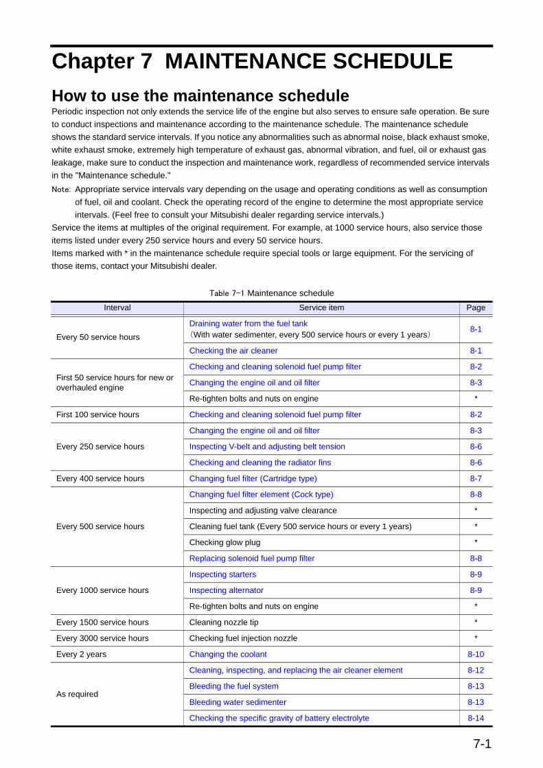
7-1
Chapter 7 MAINTENANCE SCHEDULEHow to use the maintenance schedulePeriodic inspection not only extends the service life of the engine but also serves to ensure safe operation. Be sure to conduct inspections and maintenance according to the maintenance schedule. The maintenance schedule shows the standard service intervals. If you notice any abnormalities such as abnormal noise, black exhaust smoke, white exhaust smoke, extremely high temperature of exhaust gas, abnormal vibration, and fuel, oil or exhaust gas leakage, make sure to conduct the inspection and maintenance work, regardless of recommended service intervals in the "Maintenance schedule." Note: Appropriate service intervals vary depending on the usage and operating conditions as well as consumption
of fuel, oil and coolant. Check the operating record of the engine to determine the most appropriate service intervals. (Feel free to consult your Mitsubishi dealer regarding service intervals.)
Service the items at multiples of the original requirement. For example, at 1000 service hours, also service those items listed under every 250 service hours and every 50 service hours.Items marked with * in the maintenance schedule require special tools or large equipment. For the servicing of those items, contact your Mitsubishi dealer.
Table 7-1 Maintenance scheduleInterval Service item Page
Every 50 service hoursDraining water from the fuel tank(With water sedimenter, every 500 service hours or every 1 years)
8-1
Checking the air cleaner 8-1
First 50 service hours for new or overhauled engine
Checking and cleaning solenoid fuel pump filter 8-2
Changing the engine oil and oil filter 8-3
Re-tighten bolts and nuts on engine *
First 100 service hours Checking and cleaning solenoid fuel pump filter 8-2
Every 250 service hours
Changing the engine oil and oil filter 8-3
Inspecting V-belt and adjusting belt tension 8-6
Checking and cleaning the radiator fins 8-6
Every 400 service hours Changing fuel filter (Cartridge type) 8-7
Every 500 service hours
Changing fuel filter element (Cock type) 8-8
Inspecting and adjusting valve clearance *
Cleaning fuel tank (Every 500 service hours or every 1 years) *
Checking glow plug *
Replacing solenoid fuel pump filter 8-8
Every 1000 service hours
Inspecting starters 8-9
Inspecting alternator 8-9
Re-tighten bolts and nuts on engine *
Every 1500 service hours Cleaning nozzle tip *
Every 3000 service hours Checking fuel injection nozzle *
Every 2 years Changing the coolant 8-10
As required
Cleaning, inspecting, and replacing the air cleaner element 8-12
Bleeding the fuel system 8-13
Bleeding water sedimenter 8-13
Checking the specific gravity of battery electrolyte 8-14

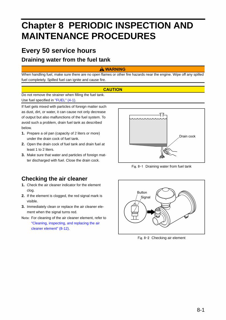
Chapter 8 PERIODIC INSPECTION AND MAINTENANCE PROCEDURESEvery 50 service hoursDraining water from the fuel tank
When handling fuel, make sure there are no open flames or other fire hazards near the engine. Wipe off any spilled fuel completely. Spilled fuel can ignite and cause fire.
Do not remove the strainer when filling the fuel tank. Use fuel specified in "FUEL" (4-1).
If fuel gets mixed with particles of foreign matter such as dust, dirt, or water, it can cause not only decrease of output but also malfunctions of the fuel system. To avoid such a problem, drain fuel tank as described below.1. Prepare a oil pan (capacity of 2 liters or more)
under the drain cock of fuel tank.2. Open the drain cock of fuel tank and drain fuel at
least 1 to 2 liters.3. Make sure that water and particles of foreign mat-
ter discharged with fuel. Close the drain cock.
Fig. 8-1 Draining water from fuel tank
Checking the air cleaner1. Check the air cleaner indicator for the element
clog.2. If the element is clogged, the red signal mark is
visible.3. Immediately clean or replace the air cleaner ele-
ment when the signal turns red.Note: For cleaning of the air cleaner element, refer to
"Cleaning, inspecting, and replacing the air cleaner element" (8-12).
Fig. 8-2 Checking air element
8-1
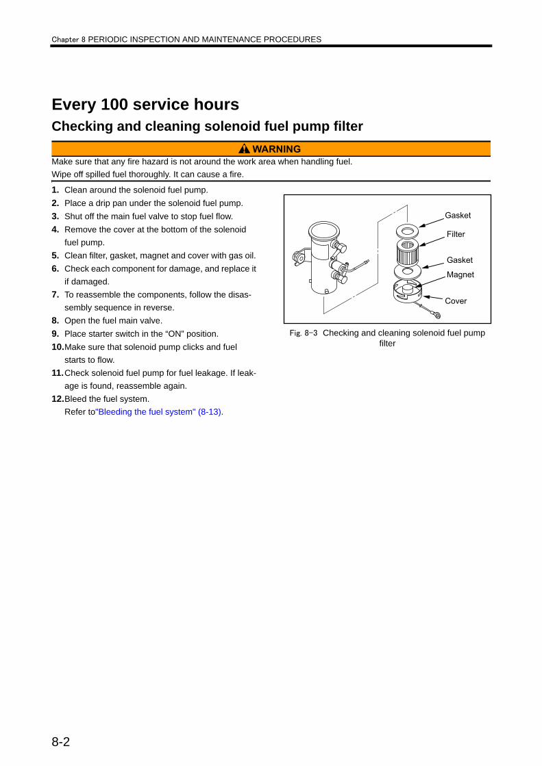
Chapter 8 PERIODIC INSPECTION AND MAINTENANCE PROCEDURES
Every 100 service hoursChecking and cleaning solenoid fuel pump filter
Make sure that any fire hazard is not around the work area when handling fuel.Wipe off spilled fuel thoroughly. It can cause a fire.
1. Clean around the solenoid fuel pump.2. Place a drip pan under the solenoid fuel pump.3. Shut off the main fuel valve to stop fuel flow.4. Remove the cover at the bottom of the solenoid
fuel pump.5. Clean filter, gasket, magnet and cover with gas oil. 6. Check each component for damage, and replace it
if damaged.7. To reassemble the components, follow the disas-
sembly sequence in reverse.8. Open the fuel main valve.9. Place starter switch in the “ON” position.10.Make sure that solenoid pump clicks and fuel
starts to flow.11.Check solenoid fuel pump for fuel leakage. If leak-
age is found, reassemble again.12.Bleed the fuel system.
Refer to"Bleeding the fuel system" (8-13).
Fig. 8-3 Checking and cleaning solenoid fuel pump filter
8-2

Chapter 8 PERIODIC INSPECTION AND MAINTENANCE PROCEDURES
Every 250 service hoursChanging the engine oil and oil filter
When draining oil or changing the oil filter, wear gloves. Hot engine oil and parts may cause burns.
Do not dump waste oil. It is forbidden by law. Consult your Mitsubishi dealer for disposal of waste oil.Change engine oil and the oil filter at the same time.Also checking and analyzing the oil properties is recommended when changing the engine oil.Do not reuse the oil filter element, as it is a paper type.
Draining engine oilAfter the engine has stopped, drain engine oil from the engine oil drain port.Note: Draining by suction should be avoided.
Fig. 8-4 Engine oil drain plug
8-3
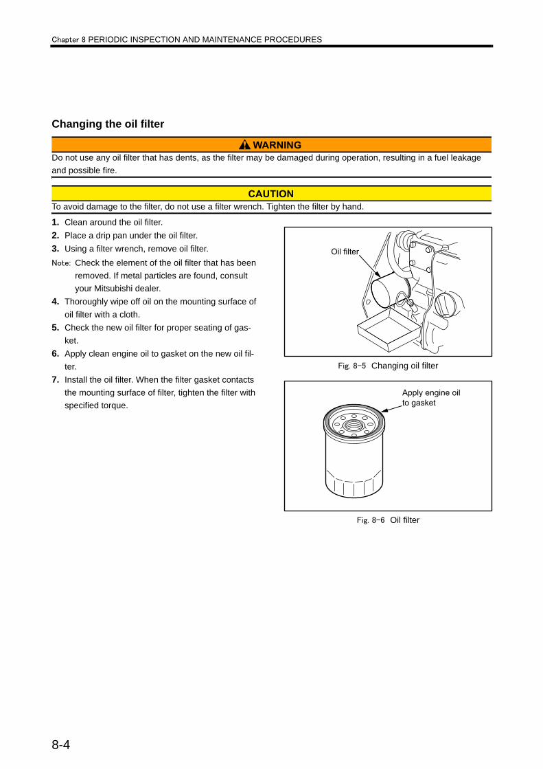
Chapter 8 PERIODIC INSPECTION AND MAINTENANCE PROCEDURES
Changing the oil filter
Do not use any oil filter that has dents, as the filter may be damaged during operation, resulting in a fuel leakage and possible fire.
To avoid damage to the filter, do not use a filter wrench. Tighten the filter by hand.
1. Clean around the oil filter.2. Place a drip pan under the oil filter.3. Using a filter wrench, remove oil filter.Note: Check the element of the oil filter that has been
removed. If metal particles are found, consult your Mitsubishi dealer.
4. Thoroughly wipe off oil on the mounting surface of oil filter with a cloth.
5. Check the new oil filter for proper seating of gas-ket.
6. Apply clean engine oil to gasket on the new oil fil-ter.
7. Install the oil filter. When the filter gasket contacts the mounting surface of filter, tighten the filter with specified torque.
Fig. 8-5 Changing oil filter
Fig. 8-6 Oil filter
8-4

Chapter 8 PERIODIC INSPECTION AND MAINTENANCE PROCEDURES
Refilling engine oil1. Make sure that the engine oil drain plug is closed.2. Remove the oil filler cap.3. Fill the engine oil pan with specified engine oil to
the specified level.Note: For engine oil, refer to "ENGINE OIL" (5-1). For
engine oil capacity, refer to "MAIN SPECIFICA-TIONS" (12-1).
4. Check the oil level in the oil pan as follows: Pull out the oil level gauge, and wipe it with a cloth.
5. Insert the oil level gauge fully into the oil level gauge guide, then pull the gauge out again. The oil level should be between the MAXIMUM and MINI-MUM marks on the oil level gauge. If the oil level is low, add engine oil of the specified type.
6. Check the oil pan and other parts for oil leakage. Repair any oil leakage found.
7. Shut off the fuel supply and crank the engine for about 10 seconds or less using the starters, and wait for about 1 minute.
8. Perform the above cranking operation again to cir-culate oil in the engine.
To crank the engine, shut off the fuel supply to the engine and operate the starters.
9. Check the oil level with the oil level gauge again, and add oil to the specified level.
Fig. 8-7 Oil filler and oil level gauge
8-5

Chapter 8 PERIODIC INSPECTION AND MAINTENANCE PROCEDURES
Inspecting V-belt and adjusting belt tension
If defects such as cuts or surface separations are found on V-belt during inspection, replace V-belt. Keep oil and grease away from the belt, since they may cause the belt to slip and shorten the service life.Excessive V-belt tension can cause rapid wear of the alternator bearing and shorten the service life of the belt. Adjust belt tension accurately by following the procedures below.
Inspecting V-belt1. Inspect V-belt for defects such as wear, cuts or surface separations. If defects are found, replace V-belt with a
new belt.2. Inspect belt tension (deflection amount) as instructed below:
Push the belt downward at the midway between pulleys. If the deflection is 10 mm [0.39 in.] , the tension is cor-rect.V-belt pushing force:Approx. 98 N {10 kgf} [22 lbf]If the tension is out of the specified value, adjust belt tension.
Adjusting V-belt tension1. Remove belt cover that covers V-belt.2. Loosen all retaining bolts of the alternator and
adjusting plate.3. Insert a bar between the alternator and cylinder
block and use leverage to move the alternator to have proper V-belt tension.
4. While V-belt tension is appropriate, retighten all the retaining bolts of the alternator and adjusting plate.
5. Reinstall the belt cover.
Fig. 8-8 Tension adjusting V-belt
Checking and cleaning the radi-ator fins
When using compressed air, wear protective gear such as safety glasses, a hard hat and gloves. Work-ing without protective gear can result in a severe per-sonal injury.
Check the radiator fins for holes and cracks.To clean the radiator fins, blow compressed air from the opposite direction of the normal air flow.
Fig. 8-9 Cleaning radiator fins
8-6
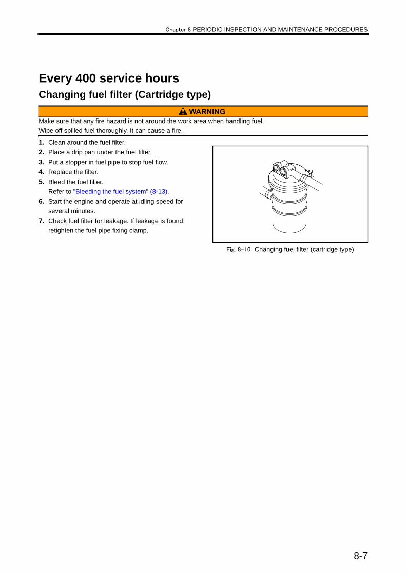
Chapter 8 PERIODIC INSPECTION AND MAINTENANCE PROCEDURES
Every 400 service hoursChanging fuel filter (Cartridge type)
Make sure that any fire hazard is not around the work area when handling fuel.Wipe off spilled fuel thoroughly. It can cause a fire.
1. Clean around the fuel filter.2. Place a drip pan under the fuel filter.3. Put a stopper in fuel pipe to stop fuel flow. 4. Replace the filter.5. Bleed the fuel filter.
Refer to "Bleeding the fuel system" (8-13).6. Start the engine and operate at idling speed for
several minutes.7. Check fuel filter for leakage. If leakage is found,
retighten the fuel pipe fixing clamp.
Fig. 8-10 Changing fuel filter (cartridge type)
8-7

Chapter 8 PERIODIC INSPECTION AND MAINTENANCE PROCEDURES
Every 500 service hoursChanging fuel filter element (Cock type)
Make sure that any fire hazard is not around the work area when handling fuel.Wipe off spilled fuel thoroughly. It can cause a fire.
1. Clean around the fuel filter.2. Place a drip pan under the fuel filter.3. Place the cock in the “OFF” position to stop fuel
flow. 4. Remove the ring nut from the fuel filter and replace
the filter element in the cup with a new one.5. Paying attention to O-ring, install the cup with the
filter element and secure it with the ring nut.6. Bleed the fuel filter.
Refer to "Bleeding the fuel system" (8-13).7. Place the cock in the "ON" position, and operate
the engine at idling speed for several minutes.8. Check fuel filter for leakage. If leakage is found,
loosen ring nut and check O-ring for damage.
Fig. 8-11 Changing fuel filter element(change cock type)
Replacing solenoid fuel pump filter
Make sure that any fire hazard is not around the work area when handling fuel.Wipe off spilled fuel thoroughly. It can cause a fire.
1. Clean around the solenoid fuel pump.2. Place a drip pan under the solenoid fuel pump.3. Shut off the main fuel valve to stop fuel flow.4. Remove the cover at the bottom of the solenoid
fuel pump.5. Replace the filter.6. Check each component for damage, and replace it
if damaged.7. To reassemble the components, follow the disas-
sembly sequence in reverse.8. Open the fuel main valve.9. Place starter switch in the “ON” position.10.Make sure that solenoid pump clicks and fuel
starts to flow.11.Check solenoid fuel pump for fuel leakage. If leak-
age is found, reassemble again.12.Bleed the fuel system.
Refer to "Bleeding the fuel system" (8-13).
Fig. 8-12 Changing solenoid fuel pump filter
8-8

Chapter 8 PERIODIC INSPECTION AND MAINTENANCE PROCEDURES
Every 1000 service hoursInspecting startersCheck the exterior of the starters for damage.If the starters are dusty, blow dirt using compressed air.Note: If the starters are defective, consult a Mitsubishi
dealer.
Fig. 8-13 Checking starter
Inspecting alternatorVisually check the alternator for damage.If the alternator is dusty, blow off dust using com-pressed air.Remove the belt, and turn the pulley by hand to make sure that it rotates smoothly.Note: If defects are found in the alternator, contact
your Mitsubishi dealer.
Fig. 8-14 Inspecting alternator
8-9

Chapter 8 PERIODIC INSPECTION AND MAINTENANCE PROCEDURES
Every 2 yearsChanging the coolant
Do not remove the radiator cap until the engine has cooled to the room temperature. When removing the radiator cap, place a cloth over the cap, and loosen the cap about a half-turn or place the lever in the upright position to release internal pressure. Never open the radiator cap while the engine is hot, as it causes steam and hot coolant to blow out and could result in serious burns. Coolant (containing LLC) drained from the engine is toxic. Do not dispose of coolant into regular sewage. For disposal of used coolant, consult your Mitsubishi dealer.
The service life of LLC is 2 years. Be sure to change coolant at least once every 2 years.
Fig. 8-15 Radiator cap
Draining the coolant1. When draining coolant immediately after engine
operation, let the engine idle at low idling speed for 5 to 6 minutes to lower the coolant temperature to 70 to 80°C [158 to 176°F].
2. Open the radiator cap.3. Place coolant receiving cans under the drain cocks
on the engine, and open the drain cocks to drain the coolant.
Cleaning the cooling system1. Close drain cocks and plugs.2. Pour in a cleaning solution (a solution that is non-
corrosive to rubber and metals) in the cooling sys-tem, and operate the engine at 800 to 900 min-1 for about 15 minutes, then drain the cleaning solution.
3. Close drain cocks and plugs.4. Pour in fresh water, and operate the engine at 800
to 900 min-1 for about 10 minutes. Repeat rinsing until the draining water becomes clear and clean.
Fig. 8-16 Draining coolant (radiator)
Fig. 8-17 Draining coolant (engine main parts)
8-10

Chapter 8 PERIODIC INSPECTION AND MAINTENANCE PROCEDURES
Refilling the coolant1. Make sure drain cocks and plugs are closed tightly.2. Remove the radiator cap, and pour in undiluted
LLC. Note: Determine the amounts of LLC and water to be
added by using the LLC concentration chart. For coolant, refer to "COOLANT" (6-1).For coolant capacity, refer to "MAIN SPECIFI-CATIONS" (12-1).
3. Pour in water (soft water with minimal impurities, such as tap water) slowly to the full level.
4. Check the radiator and other parts for coolant leaks. If a coolant leak is found, repair it.
5. When coolant reaches the full level, close the radi-ator cap securely.
6. Shut off the fuel supply and crank the engine for about 10 seconds or less using the starter. Wait for about 1 minute, then repeat the above cranking operation to remove air from the water pump.
To crank the engine, shut off the fuel supply to the engine and operate the starters.
7. Check the coolant level in the radiator. If the engine is equipped with a reserve tank, fill the reserve tank with coolant to the full level as well.
When adding coolant, use a coolant that has the same LLC concentration as the coolant already in the radia-tor.
Fig. 8-18 Radiator
Fig. 8-19 Reserve tank
8-11
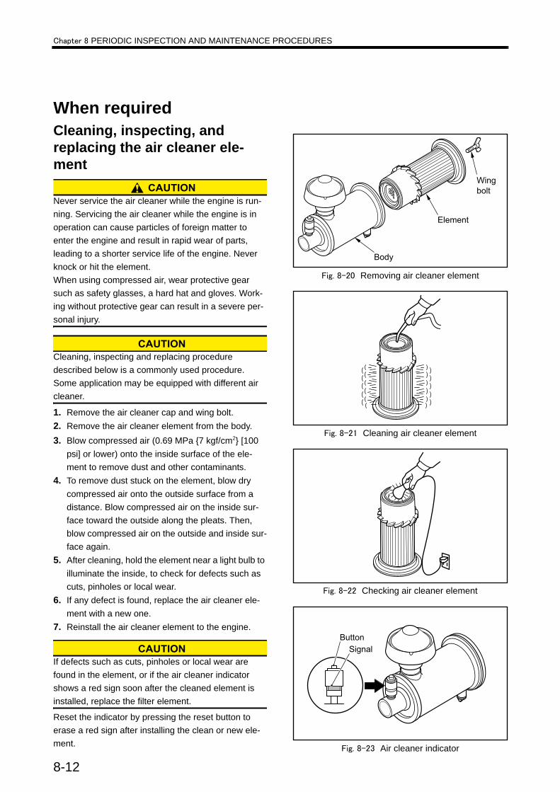
Chapter 8 PERIODIC INSPECTION AND MAINTENANCE PROCEDURES
When requiredCleaning, inspecting, and replacing the air cleaner ele-ment
Never service the air cleaner while the engine is run-ning. Servicing the air cleaner while the engine is in operation can cause particles of foreign matter to enter the engine and result in rapid wear of parts, leading to a shorter service life of the engine. Never knock or hit the element.When using compressed air, wear protective gear such as safety glasses, a hard hat and gloves. Work-ing without protective gear can result in a severe per-sonal injury.
Cleaning, inspecting and replacing procedure described below is a commonly used procedure.Some application may be equipped with different air cleaner.
1. Remove the air cleaner cap and wing bolt.2. Remove the air cleaner element from the body.3. Blow compressed air (0.69 MPa {7 kgf/cm2} [100
psi] or lower) onto the inside surface of the ele-ment to remove dust and other contaminants.
4. To remove dust stuck on the element, blow dry compressed air onto the outside surface from a distance. Blow compressed air on the inside sur-face toward the outside along the pleats. Then, blow compressed air on the outside and inside sur-face again.
5. After cleaning, hold the element near a light bulb to illuminate the inside, to check for defects such as cuts, pinholes or local wear.
6. If any defect is found, replace the air cleaner ele-ment with a new one.
7. Reinstall the air cleaner element to the engine.
If defects such as cuts, pinholes or local wear are found in the element, or if the air cleaner indicator shows a red sign soon after the cleaned element is installed, replace the filter element.
Reset the indicator by pressing the reset button to erase a red sign after installing the clean or new ele-ment.
Fig. 8-20 Removing air cleaner element
Fig. 8-21 Cleaning air cleaner element
Fig. 8-22 Checking air cleaner element
Fig. 8-23 Air cleaner indicator
8-12
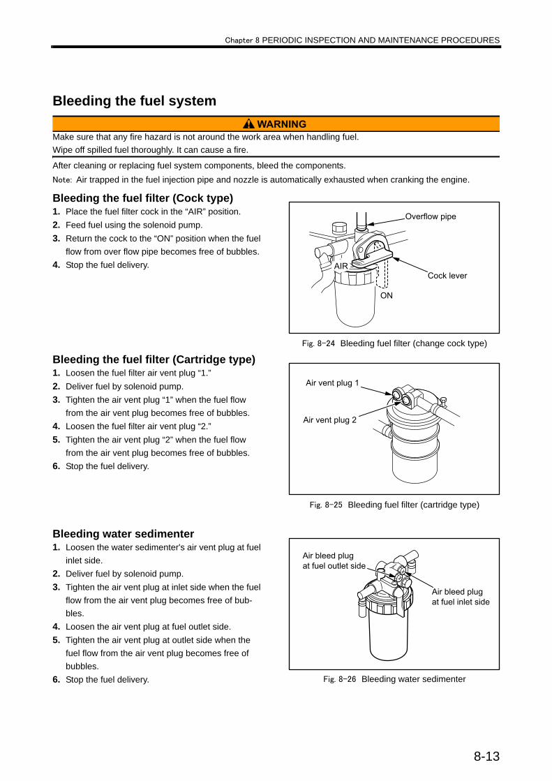
Chapter 8 PERIODIC INSPECTION AND MAINTENANCE PROCEDURES
Bleeding the fuel system
Make sure that any fire hazard is not around the work area when handling fuel.Wipe off spilled fuel thoroughly. It can cause a fire.
After cleaning or replacing fuel system components, bleed the components.Note: Air trapped in the fuel injection pipe and nozzle is automatically exhausted when cranking the engine.
Bleeding the fuel filter (Cock type) 1. Place the fuel filter cock in the “AIR” position.2. Feed fuel using the solenoid pump.3. Return the cock to the “ON” position when the fuel
flow from over flow pipe becomes free of bubbles.4. Stop the fuel delivery.
Fig. 8-24 Bleeding fuel filter (change cock type)
Bleeding the fuel filter (Cartridge type)1. Loosen the fuel filter air vent plug “1.”2. Deliver fuel by solenoid pump.3. Tighten the air vent plug “1” when the fuel flow
from the air vent plug becomes free of bubbles.4. Loosen the fuel filter air vent plug “2.”5. Tighten the air vent plug “2” when the fuel flow
from the air vent plug becomes free of bubbles.6. Stop the fuel delivery.
Fig. 8-25 Bleeding fuel filter (cartridge type)
Bleeding water sedimenter1. Loosen the water sedimenter's air vent plug at fuel
inlet side.2. Deliver fuel by solenoid pump.3. Tighten the air vent plug at inlet side when the fuel
flow from the air vent plug becomes free of bub-bles.
4. Loosen the air vent plug at fuel outlet side.5. Tighten the air vent plug at outlet side when the
fuel flow from the air vent plug becomes free of bubbles.
6. Stop the fuel delivery. Fig. 8-26 Bleeding water sedimenter
8-13

Chapter 8 PERIODIC INSPECTION AND MAINTENANCE PROCEDURES
Draining water sedimenter
Make sure that any fire hazard is not around the work area when handling fuel.Wipe off spilled fuel thoroughly. It can cause a fire.
1. Clean around the water sedimenter.2. Place a drip pan under the water sedimenter.3. Place the cock in the "C" (Close) position to stop
fuel flow. 4. Remove the ring nut and remove the cup.5. Drain the cup and clear the element with gas oil.6. Paying attention to O-ring, install the cup with the
filter element and secure it with the ring nut.7. Bleed the water sedimenter.
Refer to "Bleeding water sedimenter" (8-13).8. Place the cock in the "O" (Open) position, and
operate the engine at idling speed for several min-utes.
9. Check water sedimenter for leakage. If leakage is found, loosen ring nut and check O-ring for dam-age.
Fig. 8-27 Draining water from sedimenter
Checking the specific gravity of battery electrolyte
If battery electrolyte is spilled on your skin, flush immediately with plenty of water. If battery electrolyte enters the eyes, flush them immediately with lots of fresh water and seek medical attention at once. Do not use open flames or other fire hazards near the battery. When handling the battery, be careful of sparks generated by accidental short-ing. For other cautions in handling the battery, refer to "Service battery" (1-5).
Check the specific gravity of the electrolyte. If the spe-cific gravity measured at 20°C [68°F] is lower than 1.22, then charge the battery.
Fig. 8-28 Checking specific gravity of battery electrolyte
Table 8-1 Specific gravity of electrolyteSpecific gravity at
20°C [68°F] Condition Remedy
From 1.26 to 1.28 Fully charged -
From 1.22 to 1.26 Charged Charge
Less than 1.22 Discharged Charge
8-14
Chapter 9 LONG-TERM STORAGELong-term storageThe following describes how to store the engine in a non-operable condition for three months or more and in an operable condition for three months or more.If the engine has been left unattended for three months or more, the internal engine parts can rust, and that may cause damage to the engine. When stor-ing the engine for an extended period of time, be sure to follow the directions below.
Storing the engine in a non-operable condition for 3 months or morePreparation for storage1. Drain engine oil, and pour rust-preventive oil (NP-
10-2) into the engine.2. Prepare a fuel mixture containing 50% rust-pre-
ventive oil (NP-9), and fill the fuel tank with it.3. Operate the engine at a speed of 800 to 1000
min-1 (idling) for 5 to 10 minutes under no load.4. Immediately before stopping the engine, spray vol-
atile corrosion inhibitor (V.C.I.) through the inlet port to prevent rust on the air intake system.
5. With the engine stopped, drain the fuel mixture from the fuel tank.
6. Apply rust-preventive oil (NP-3) liberally on the exposed sections of the machining.
7. Seal the air inlet, exhaust outlet, breather and other openings with an adhesive cloth tape.
8. Loosen the V-belt.9. Wrap adhesive cloth tape on the terminals of the
starters and alternator, and seal the openings. Cover these sections with polyethylene sheet or processed polyethylene paper, and place desic-cants in the polyethylene covers.
10. Disconnect the cables from the battery terminals, and charge the battery. Clean the terminals, apply a thin coat of grease to the terminals, and store the battery in a cool and dry room.
11. Cover the entire engine.
Note :(a) Store the engine in a well-ventilated indoor area.
(b) It is not necessary to drain coolant since it contains LLC. (Add LLC to increase the con-centration to between 30 and 60%.)
(c) Post a sign at an easily noticeable place to warn that the rust-preventive oil in the engine must be replaced with engine oil, and the fuel tank must be filled with fuel before operating the engine for the first time after storage.
(d) New engine oil can substitute for rust-pre-ventive oil (NP-10-2).
Recommended rust-preventive oil and corrosion inhibitor
Maintenance during storageCharge the battery once a month.First, check the battery electrolyte for correct level and then charge the battery.
Table 9-1 Recommended rust-preventive oil and corrosion inhibitor
JIS No. Recommendedproduct Application
K2246
NP-3 Nippon Oil CorporationAnti Rust P-1400
Prevention of rust on exposed machine surfaces
NP-9 Nippon Oil CorporationAnti Rust P-2400
Prevention of rust in fuel system
NP-10-2 Nippon Oil CorporationAnti Rust P-230
Prevention of rust in lubricating system
Z1519 -Ryoukou Kagaku V.C.I. Diana volatilecorrosion inhibitor
Prevention of rust in air intake sys-tem
9-1
Chapter 9 LONG-TERM STORAGE
Using the engine after storage1. Remove the cover from the engine.2. Connect a fully charged battery.3. Remove the covers from the starters and alterna-
tor.4. Adjust the tension of V-belt.Note: For the adjustment of V-belt tension, refer to
"Adjusting V-belt tension" (8-6).5. Remove sealing tapes from the openings of the
engine.6. Drain rust-preventive oil, and pour in appropriate
engine oil.Note: For engine oil, refer to "ENGINE OIL" (5-1)7. Fill the fuel tank with fuel, and bleed the fuel sys-
tem.Note: For bleeding fuel system, refer to "Bleeding the
fuel system" (8-13).8. Inspect the entire engine.9. Remove the rocker covers, and lubricate the valve
mechanisms.10. Shut off the fuel supply and crank the engine for
about 10 seconds. Then repeat this cranking 3 times at intervals of about 1 minute.
To crank the engine, shut off the fuel supply to the engine and operate the starter.
11. Make sure the engine oil pressure rises.12. Start the engineNote: For starting the engine, refer to "Starting" (3-4).13. Conduct a warm-up operation for a sufficient dura-
tion.14. Apply load and increase the engine speed to the
rated speed.
Storing the engine in an operable condition for 3 months or moreWhen the engine is not operated during storage of three months or more, internal engine parts can rust and lose oil film. As a result, the engine can seize when it is started after storage. To prevent such a risk, the engine must be operated periodically during stor-age.
Operating the engine for main-tenanceOperate the engine for maintenance at least once a month as described below.1. With the fuel shut off (press the engine stop button
to shut off the fuel injection), operate the starter twice at intervals of about 15 seconds and check to see if the engine oil pressure increases.
2. After the engine starts, operate under no load for 5 to 10 minutes.
Note: For engine operation, refer to "OPERATION" (3-1).
9-2
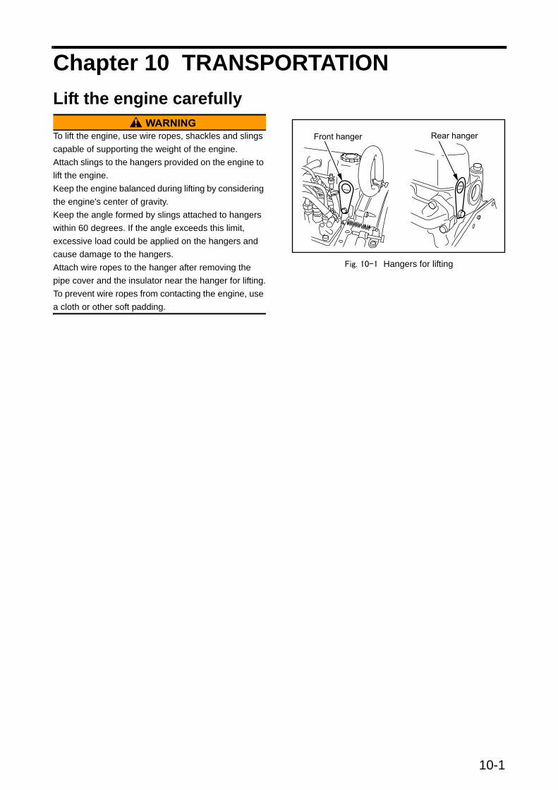
10-1
Chapter 10 TRANSPORTATIONLift the engine carefully
To lift the engine, use wire ropes, shackles and slings capable of supporting the weight of the engine.Attach slings to the hangers provided on the engine to lift the engine.Keep the engine balanced during lifting by considering the engine's center of gravity.Keep the angle formed by slings attached to hangers within 60 degrees. If the angle exceeds this limit, excessive load could be applied on the hangers and cause damage to the hangers.Attach wire ropes to the hanger after removing the pipe cover and the insulator near the hanger for lifting.To prevent wire ropes from contacting the engine, use a cloth or other soft padding.
Fig. 10-1 Hangers for lifting


Chapter 11 TROUBLESHOOTINGGeneral precautionsContact your Mitsubishi dealer for repair serviceRepairing a malfunctioning engine may require special equipment or involve potentially dangerous work, except for relatively simple procedures such as the change and addition of fuel, engine oil and coolant. In the event of the engine failure, contact your Mitsubishi dealer.
Considerations before workBefore troubleshooting, consider possible causes of the problem and try to find out if the same problem has occurred in the past. Check the parts that may be causing the problem in the most efficient order.When disassembling a component, pay close atten-tion to the disassembly sequence so that you can reassemble the component in reverse order of disas-sembly.
Cautions against contaminationDust and particles of foreign matter are the most com-mon cause of rapid wear of parts. When disassembling a component, take measures to prevent dust and foreign particles from entering the component being disassembled.
Cautions regarding parts han-dlingHandle parts carefully.When replacing parts, use only genuine parts by refer-ring to the parts catalog.
Work safetyBe sure to use wrenches of the correct size. Using a wrench of the wrong size not only damages nuts but can also cause the personal injury.Use correct tools and perform work with utmost cau-tion.Be sure to accurately estimate the weight of the part being dismounted. If the removed part is much heavier than you have estimated, it may fall down during lifting and can result in the damage to the parts or personal injury.
11-1
Chapter 11 TROUBLESHOOTING
How to troubleshootThe starter does not crank or cranks slowly, resulting in start failure
The starter cranks, but the engine does not start
Table 11-1 The starter does not crank or cranks slowly, resulting in start failureCause Remedy
Electrical system
Blown fuse Change fuse
Faulty wiring connection between battery and starter switch Connect wire correctly
Faulty wiring connection between battery, starter and starter switch Connect wire correctly
Insufficiently charged battery Inspect and adjust V-belt tension. Refer to "Inspecting V-belt and adjusting belt tension" (8-6).
Specific gravity of battery fluid too low Charge battery
Faulty battery Install new battery
Faulty starter or starter relay Consult a Mitsubishi dealer
Lubricating sys-tem Oil viscosity too high Use appropriate engine oil. Refer to "ENGINE OIL" (5-1).
Fuel system
Air in fuel system Bleed fuel system. Refer to "Bleeding the fuel system" (8-13).
Low fuel level Add fuel
Clogged fuel filters Change fuel filters.Refer to "Changing fuel filter (Cartridge type)" (8-7), "Changing fuel filter element (Cock type)" (8-8).
Faulty fuel feed pump Consult a Mitsubishi dealer
Faulty fuel injection pump Consult a Mitsubishi dealer
Engine mechani-cal
Faulty moving parts (interference between valves and pistons, or foreign matter in cylinders)
Consult a Mitsubishi dealer
Table 11-2 The starter cranks, but the engine does not startCause. Remedy
Fuel system
Empty fuel tank Add fuel, and bleed fuel system. Refer to"FUEL" (4-1).
Damaged fuel pipe Consult a Mitsubishi dealer
Loose fuel pipe connection Tighten connection. Consult a Mitsubishi dealer
Improper fuel Use proper fuel. Refer to "FUEL" (4-1).
Dust or water mixed in fuel Remove dust or water from fuel tank. Refer to "Draining water from the fuel tank" (8-1).
Clogged fuel filtersReplace fuel filters. Refer to "Changing fuel filter (Car-tridge type)" (8-7), "Changing fuel filter element (Cocktype)" (8-8).
Faulty fuel feed pump Consult a Mitsubishi dealer
Faulty fuel injection pump Consult a Mitsubishi dealer
Air intake system Clogged air cleaner or pre-cleaner Clean air cleaner or pre-cleaner . Refer to "Cleaning, inspecting, and replacing the air cleaner element" (8-12).
Engine mechanical
Compression pressure low (damaged cylinder liner, piston or piston ring, or faulty valve seat or nozzle packing seal)
Consult a Mitsubishi dealer
11-2

Chapter 11 TROUBLESHOOTING
Other problems and countermeasuresEngine output is low
Exhaust smoke is white or blue
Table 11-3 Engine output is lowCause Remedy
Engine oil viscosity too high Use engine oil of appropriate viscosity according to ambient temper-ature. Refer to "ENGINE OIL" (5-1).
Improper fuel Use proper fuel. Refer to "FUEL" (4-1).
Insufficient air intake (clogged air cleaner) Clean air cleaner element, or replace if necessary. Refer to "Clean-ing, inspecting, and replacing the air cleaner element" (8-12).
Engine overcooling Cover the radiator or contact your local Mitsubishi dealer
Clogged fuel filter Replace fuel filters. Refer to "Changing fuel filter (Cartridge type)" (8-7), "Changing fuel filter element (Cock type)" (8-8).
Insufficient cooling (overheating) Contact your local Mitsubishi dealer
Incorrect valve clearance Contact your local Mitsubishi dealer
Faulty fuel feed pump Contact your local Mitsubishi dealer
Faulty fuel injection pump Contact your local Mitsubishi dealer
Faulty fuel injection nozzles Contact your local Mitsubishi dealer
Incorrect fuel injection timing Contact your local Mitsubishi dealer
Low compression pressure(worn cylinder liners, worn piston rings, etc.) Contact your local Mitsubishi dealer
Table 11-4 Exhaust smoke is white or blue Cause Remedy
Excessive amount of engine oil Maintain correct oil level. Refer to "Checking the engine oil level" (3-2).
Engine oil viscosity too high Use engine oil of appropriate viscosity according to ambient tem-perature. Refer to"ENGINE OIL" (5-1).
Overcooling Cover the radiator or consult your Mitsubishi dealer
Faulty thermostat(water temperature does not rise) Contact your local Mitsubishi dealer
Faulty fuel injection nozzles(uneven injection among cylinders) Contact your local Mitsubishi dealer
Incorrect fuel injection timing Contact your local Mitsubishi dealer
Low compression pressure(worn piston liners, worn piston rings, etc.) Contact your local Mitsubishi dealer
Improper fuel (low cetane number) Use proper fuel. Refer to"FUEL" (4-1).
11-3
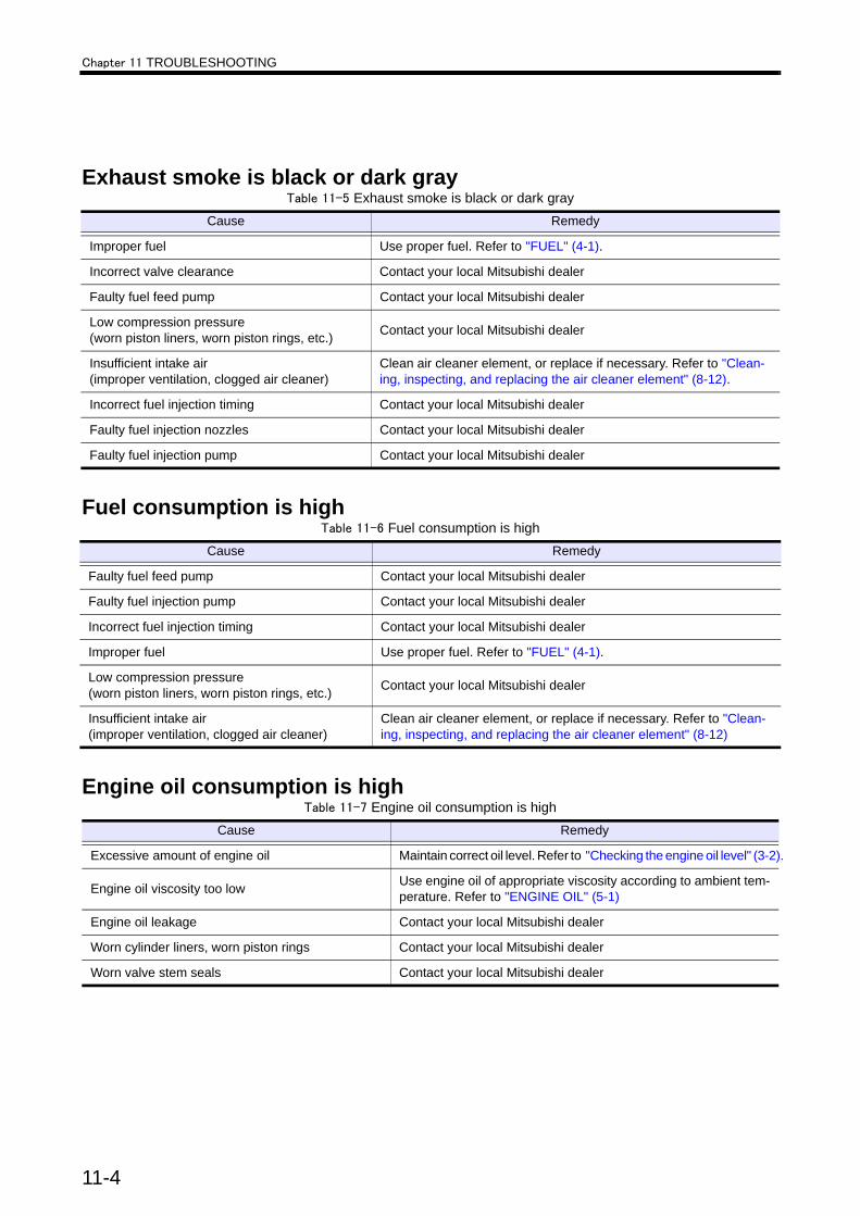
Chapter 11 TROUBLESHOOTING
Exhaust smoke is black or dark gray
Fuel consumption is high
Engine oil consumption is high
Table 11-5 Exhaust smoke is black or dark grayCause Remedy
Improper fuel Use proper fuel. Refer to "FUEL" (4-1).
Incorrect valve clearance Contact your local Mitsubishi dealer
Faulty fuel feed pump Contact your local Mitsubishi dealer
Low compression pressure(worn piston liners, worn piston rings, etc.) Contact your local Mitsubishi dealer
Insufficient intake air(improper ventilation, clogged air cleaner)
Clean air cleaner element, or replace if necessary. Refer to "Clean-ing, inspecting, and replacing the air cleaner element" (8-12).
Incorrect fuel injection timing Contact your local Mitsubishi dealer
Faulty fuel injection nozzles Contact your local Mitsubishi dealer
Faulty fuel injection pump Contact your local Mitsubishi dealer
Table 11-6 Fuel consumption is highCause Remedy
Faulty fuel feed pump Contact your local Mitsubishi dealer
Faulty fuel injection pump Contact your local Mitsubishi dealer
Incorrect fuel injection timing Contact your local Mitsubishi dealer
Improper fuel Use proper fuel. Refer to "FUEL" (4-1).
Low compression pressure(worn piston liners, worn piston rings, etc.) Contact your local Mitsubishi dealer
Insufficient intake air(improper ventilation, clogged air cleaner)
Clean air cleaner element, or replace if necessary. Refer to "Clean-ing, inspecting, and replacing the air cleaner element" (8-12)
Table 11-7 Engine oil consumption is highCause Remedy
Excessive amount of engine oil Maintain correct oil level. Refer to "Checking the engine oil level" (3-2).
Engine oil viscosity too low Use engine oil of appropriate viscosity according to ambient tem-perature. Refer to "ENGINE OIL" (5-1)
Engine oil leakage Contact your local Mitsubishi dealer
Worn cylinder liners, worn piston rings Contact your local Mitsubishi dealer
Worn valve stem seals Contact your local Mitsubishi dealer
11-4

Chapter 11 TROUBLESHOOTING
Engine overheats
Engine oil pressure is faulty
Note: If the problem cannot be corrected easily or when a problem other than those listed above occurs, Contact your local Mitsubishi dealer. When ordering replacement parts, provide the engine serial number. When requesting repair, provide the engine serial number and service hour meter reading.
When fuel has run outWhen fuel runs out during engine operation and the engine has stopped, restart the engine as described below.1. Return the starter switch to the OFF position.2. Add fuel to the fuel tank.
For filling fuel tank, refer to "Checking fuel tank oil level" (3-2).3. Bleed air from the fuel system.
For bleeding air from fuel system, refer to "Bleeding the fuel system" (8-13).4. Restart the engine.
For starting the engine, refer to "Starting" (3-4).
Table 11-8 Engine overheatsCause Remedy
Radiator, heat exchanger leakage Contact your local Mitsubishi dealer
Low coolant level Add coolant. Refer to "Checking the coolant level" (3-3).
Faulty water pump Contact your local Mitsubishi dealer
Faulty thermostat Contact your local Mitsubishi dealer
Table 11-9 Engine oil pressure is faultyCause Remedy
Insufficient amount of engine oil Maintain correct oil level. Refer to "Checking the engine oil level" (3-2).
Engine oil viscosity too low Use engine oil of appropriate viscosity according to ambient tempera-ture. Refer to "ENGINE OIL" (5-1).
Clogged oil filter Replace oil filters. Refer to "Changing the engine oil and oil filter" (8-3).
Faulty oil pump Contact your local Mitsubishi dealer
Faulty relief valve Contact your local Mitsubishi dealer
Faulty oil pressure sensor Contact your local Mitsubishi dealer
11-5

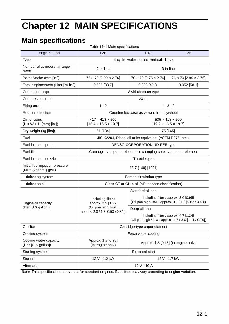
12-1
Chapter 12 MAIN SPECIFICATIONSMain specifications
Note: This specifications above are for standard engines. Each item may vary according to engine variation.
Table 12-1 Main specificationsEngine model L2E L3C L3E
Type 4-cycle, water-cooled, vertical, diesel
Number of cylinders, arrange-ment 2-in-line 3-in-line
Bore×Stroke (mm [in.]) 76 × 70 [2.99 × 2.76] 70 × 70 [2.76 × 2.76] 76 × 70 [2.99 × 2.76]
Total displacement (Liter [cu.in.]) 0.635 [38.7] 0.808 [49.3] 0.952 [58.1]
Combustion type Swirl chamber type
Compression ratio 23 : 1
Firing order 1 - 2 1 - 3 - 2
Rotation direction Counterclockwise as viewed from flywheel
Dimensions(L × W × H (mm) [in.])
417 × 418 × 500[16.4 × 16.5 × 19.7]
505 × 418 × 500[19.9 × 16.5 × 19.7]
Dry weight (kg [lbs]) 61 [134] 75 [165]
Fuel JIS K2204, Diesel oil or its equivalent (ASTM D975, etc.).
Fuel injection pump DENSO CORPORATION ND-PER type
Fuel filter Cartridge-type paper element or changing cock-type paper element
Fuel injection nozzle Throttle type
Initial fuel injection pressure(MPa {kgf/cm²} [psi]) 13.7 {140} [1991]
Lubricating system Forced circulation type
Lubrication oil Class CF or CH-4 oil (API service classification)
Engine oil capacity(liter [U.S.gallon])
Including filter : approx. 2.5 [0.66](Oil pan high/ low :
approx. 2.0 / 1.3 [0.53 / 0.34])
Standard oil pan
Including filter : approx. 3.6 [0.95](Oil pan high/ low : approx. 3.1 / 1.8 [0.82 / 0.48])
Deep oil pan
Including filter : approx. 4.7 [1.24](Oil pan high / low : approx. 4.2 / 3.0 [1.11 / 0.79])
Oil filter Cartridge-type paper element
Cooling system Force water cooling
Cooling water capacity(liter [U.S.gallon])
Approx. 1.2 [0.32] (in engine only) Approx. 1.8 [0.48] (in engine only)
Starting system Electrical start
Starter 12 V - 1.2 kW 12 V - 1.7 kW
Alternator 12 V - 40 A