Embed Size (px)
Citation preview

Original instructions
Operatingmanual
DesiCool™
AirTreatmentSystem
TEN-DSC-E1708 ©MuntersEuropeAB2017

Tableof contentsTableof contents .. . . . . . . . . . . . . . . . . . . . . . . . . . ii
1 Introduction .. . . . . . . . . . . . . . . . . . . . . . . . . . . . . . . . 11.1 Definition . . . . . . . . . . . . . . . . . . . . . . . . . . . . . . . 11.2 About thismanual . . . . . . . . . . . . . . . . . . . . . 11.3 Warnings .. . . . . . . . . . . . . . . . . . . . . . . . . . . . . . 11.4 Warranty . . . . . . . . . . . . . . . . . . . . . . . . . . . . . . . 11.5 Inspectionof delivery . . . . . . . . . . . . . . . . . . 21.6 Technical data . . . . . . . . . . . . . . . . . . . . . . . . . 2
2 Safety . . . . . . . . . . . . . . . . . . . . . . . . . . . . . . . . . . . . . . . . . 32.1 Intendeduse .. . . . . . . . . . . . . . . . . . . . . . . . . . 32.2 Safe installation, operationand
maintenance .. . . . . . . . . . . . . . . . . . . . . . . . . . 32.2.1 Electrical hazard . . . . . . . . . . . . . . . 42.2.2 Physical hazard . . . . . . . . . . . . . . . . 52.2.3 Property hazard . . . . . . . . . . . . . . . . 6
2.3 Residual risks . . . . . . . . . . . . . . . . . . . . . . . . . . 72.4 Warningsigns .. . . . . . . . . . . . . . . . . . . . . . . . 82.5 Emergencystop .. . . . . . . . . . . . . . . . . . . . . . 8
3 Systemdesignand function .. . . . . . . . . . . . . 93.1 Main function . . . . . . . . . . . . . . . . . . . . . . . . . . 93.2 Systemdesign .. . . . . . . . . . . . . . . . . . . . . . . . 93.3 Basic sensors layout . . . . . . . . . . . . . . . . . . 113.4 Pre- andpost-treatment . . . . . . . . . . . . . . 12
4 Maincomponentsdescription .. . . . . . . . . . . 134.1 Desiccant rotor . . . . . . . . . . . . . . . . . . . . . . . . 13
4.1.1 Function . . . . . . . . . . . . . . . . . . . . . . . . 134.1.2 Rotormaintenance .. . . . . . . . . . . 144.1.3 Rotor seals , drivebelt anddrive
motor . . . . . . . . . . . . . . . . . . . . . . . . . . . 144.2 Thermal recovery rotor . . . . . . . . . . . . . . . . 15
4.2.1 Function . . . . . . . . . . . . . . . . . . . . . . . . 154.2.2 Rotor . . . . . . . . . . . . . . . . . . . . . . . . . . . . 154.2.3 Rotor seals , drivebelt anddrive
motor . . . . . . . . . . . . . . . . . . . . . . . . . . . 15
4.3 Water coils . . . . . . . . . . . . . . . . . . . . . . . . . . . . . 164.3.1 Cooling coils . . . . . . . . . . . . . . . . . . . . 164.3.2 Heating coils . . . . . . . . . . . . . . . . . . . 164.3.3 Frost protection . . . . . . . . . . . . . . . . 164.3.4 Droplet separator . . . . . . . . . . . . . . 164.3.5 Cleaning .. . . . . . . . . . . . . . . . . . . . . . . 174.3.6 Stoppingwater flow to the
coils . . . . . . . . . . . . . . . . . . . . . . . . . . . . . 174.4 Evaporative coolers/humidifiers . . . . . 184.5 Fans .. . . . . . . . . . . . . . . . . . . . . . . . . . . . . . . . . . . 20
4.5.1 Fan types .. . . . . . . . . . . . . . . . . . . . . . 204.5.2 Maintenance .. . . . . . . . . . . . . . . . . . 20
4.6 Filters . . . . . . . . . . . . . . . . . . . . . . . . . . . . . . . . . . . 204.6.1 Filter types .. . . . . . . . . . . . . . . . . . . . . 204.6.2 Filtermaintenance .. . . . . . . . . . . . 214.6.3 Panel filters . . . . . . . . . . . . . . . . . . . . . 214.6.4 Bagfilters . . . . . . . . . . . . . . . . . . . . . . . 21
4.7 Dampers . . . . . . . . . . . . . . . . . . . . . . . . . . . . . . . 224.8 Flexible connections . . . . . . . . . . . . . . . . . . 23
5 Commissioning .. . . . . . . . . . . . . . . . . . . . . . . . . . . 245.1 Checksbefore startingup .. . . . . . . . . . . . 245.2 Inspectionof evaporative coolers . . . . 245.3 Startingup .. . . . . . . . . . . . . . . . . . . . . . . . . . . . 25
6 Serviceandmaintenance .. . . . . . . . . . . . . . . . 266.1 Safety . . . . . . . . . . . . . . . . . . . . . . . . . . . . . . . . . . 266.2 General . . . . . . . . . . . . . . . . . . . . . . . . . . . . . . . . 286.3 Serviceoptions . . . . . . . . . . . . . . . . . . . . . . . . 286.4 Extendedwarranty . . . . . . . . . . . . . . . . . . . . 286.5 Serviceandmaintenanceschedule . . 29
7 Scrapping .. . . . . . . . . . . . . . . . . . . . . . . . . . . . . . . . . . . 318 Supplements .. . . . . . . . . . . . . . . . . . . . . . . . . . . . . . . 329 ContactMunters .. . . . . . . . . . . . . . . . . . . . . . . . . . . 33
ii Tableof contents TEN-DSC-E1708

DesiCool
1 Introduction
1.1 DefinitionTheAir Treatment Systemdescribed in thismanual is hereafter referred to as the “unit”.
1.2 About thismanualThis instructionmanual contains important safety information, a product description andmaintenanceinstructions for the delivered air treatment unit. Read all relevant parts of thismanual before operating orperforming anywork on the unit. Observance of this informationwill help you to avoid danger, tominimiserepair cost and downtime, and to increase the reliability and the service life of the air treatment unit.Thismanual should be stored in a permanent location close to the unit.Thismanual does not describe in full all themaintenancework required to guarantee the longevity andreliability of this type of equipment. Always contactMunters for service and repairs, to ensure safe and longlasting operation of the unit.The contents of thismanual can be changedwithout prior notice.
NOTE!Thismanual contains informationwhich is protectedbycopyright laws. It is not allowed to reproduceortransmit anypart of thismanualwithoutwritten consent fromMunters.
Please send any comments regarding thismanual to:Munters EuropeABTechnicalDocumentationP.O. Box 1150SE- 164 26KISTASwedenemail: [email protected]
1.3 WarningsInformation about dangers are in thismanual indicated by the commonhazard symbol:
WWWARNING!ARNING!ARNING!Indicatesapossibledanger that can lead topersonal injury.
CACACAUTION!UTION!UTION!Indicatesapossibledanger that can lead todamage to theunit or other property, or causeenvironmental damage.
NOTE!Highlights supplementary information for optimal useof theunit.
1.4 WarrantyThewarranty is based on the terms of sale and delivery ofMunters. Thewarranty is not valid if repairs ormodifications are carried outwithout thewritten agreement ofMunters, or if the unit does not operate underthe conditions agreedwithMunters. Damages resulting fromnegligence, poormaintenance or failure tocomplywith the recommendationswill not be covered by thewarranty.
TEN-DSC-E1708 Introduction 1
DesiCool
It is a condition of thewarranty that the unit for the full warranty period is serviced andmaintained by aqualifiedMunters engineer orMunters approved engineer. Access to specific and calibrated test equipmentis necessary. The service andmaintenancemust be documented for thewarranty to be valid.Thewarranty is limited to a free exchange of parts or componentswhich have failed as a result of defectsinmaterials orworkmanship.Commissioning/Start-up inspection "S" byMunters ismandatory to validate the full warranty.Always contactMunters for service or repair. Operating faults can occur if the unit ismaintainedinsufficiently or incorrectly.
1.5 InspectionofdeliveryUpon receipt, inspect the equipment before signing the delivery note. Specify any damage on the deliverynote and send a registered letter of complaint to the last company responsible for transporting theequipmentwithin three days. InformMunters of this complaint.The unitmust be fully inspectedwithin oneweek fromarrival. If a hidden fault is discovered, send aregistered letter of complaint to the haulierwithin theweek following delivery, and notifyMunters of this.
1.6 TechnicaldataThe technical data for a specific unit can be found in the separateData sheet issued for each unit.
2 Introduction TEN-DSC-E1708

DesiCool
2 Safety
2.1 IntendeduseThe unit delivered byMuntersmust only be used for the treatment of air. This includes filtering, heating,cooling, humidifying, dehumidifying and transporting air. Munters explicitly rules out any other use.The unit is designed tomeet the safety requirements, directives and standards listed in theECDeclaration ofConformity.Nomodification of the unit is allowedwithout prior approval byMunters. Attachment or installation ofadditional devices is only allowed afterwritten agreement byMunters.The conditions of operation specified in the separateData sheetmust be observed absolutely. Any other useof the equipment can cause personal injury and damage to the unit and other property.
2.2 Safe installation,operationandmaintenanceGreat effort has been placed on the design andmanufacture of the unit, to complywith applicable safetyaspects for this type of equipment.The information in thismanual includes suggestions for bestworking practice and shall in noway takeprecedence over individual responsibilities or local regulations.During operation and otherworkwith amachine it is always the responsibility of the individual to consider:■ The safety of all persons concerned.■ The safety of the unit and other property.■ The protection of the environment.Always carry out risk assessments before doing anyworkon theunit.
TEN-DSC-E1708 Safety 3
DesiCool
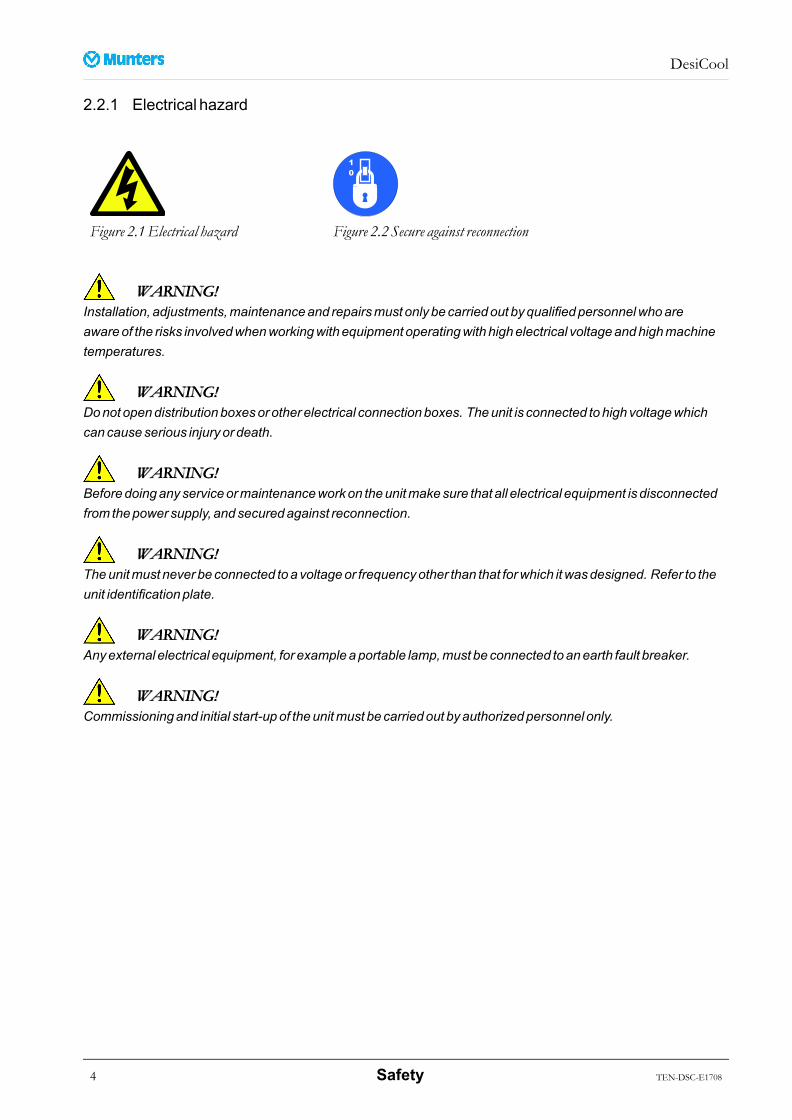
2.2.1 Electrical hazard
Figure 2.1Electrical hazard Figure 2.2 Secure against reconnection
WWWARNING!ARNING!ARNING!Installation, adjustments,maintenanceand repairsmust only becarriedout byqualifiedpersonnelwhoareawareof the risks involvedwhenworkingwithequipment operatingwithhighelectrical voltageandhighmachinetemperatures.
WWWARNING!ARNING!ARNING!Donot opendistributionboxesor other electrical connectionboxes. Theunit is connected tohighvoltagewhichcancauseserious injuryor death.
WWWARNING!ARNING!ARNING!Beforedoinganyserviceormaintenanceworkon theunitmakesure that all electrical equipment is disconnectedfrom thepower supply, andsecuredagainst reconnection.
WWWARNING!ARNING!ARNING!Theunitmust never beconnected toavoltageor frequencyother than that forwhich itwasdesigned. Refer to theunit identificationplate.
WWWARNING!ARNING!ARNING!Anyexternal electrical equipment, for exampleaportable lamp,must beconnected toanearth fault breaker.
WWWARNING!ARNING!ARNING!Commissioningand initial start-upof theunitmust becarriedout byauthorizedpersonnel only.
4 Safety TEN-DSC-E1708
DesiCool
2.2.2 Physical hazard
WWWARNING!ARNING!ARNING!Rotatinghazard. Theunit contains rotating fansandothermovingparts.
Toprevent personal injury, theunitmust be runwithall panel doors closedandall removablepanels andprotectivegridsproperly in place. Never open thedoorsor panels beforeall fansandothermovingparts havecome toacomplete stop, and themainpower is switchedoff.
Fansandothermovingparts canstart automatically andwithoutwarning.
WWWARNING!ARNING!ARNING!Theunit sectionsareheavy. Useonly approved liftingequipment adapted to theweight of the sections toavoidaccidents.
WWWARNING!ARNING!ARNING!Makesure that all pipe couplingsareproperly tightenedbefore themediumsupply for coolingor heating coilsis turnedon.
WWWARNING!ARNING!ARNING!Cleaningagents, coolingmedia, oil andgreaseare substances that aredangerous topersonal health and to theenvironment. Theymust not beallowed todrainaway into thesoil or thepublic sewer system. Thedisposal of suchsubstancesmust beeffected inaccordancewith local andnational lawand regulations.
TEN-DSC-E1708 Safety 5
DesiCool
2.2.3 Property hazard
CACACAUTION!UTION!UTION!Theunit is not intended for use in classifiedareas, nor for treatingair pollutedwith solvents, dust or otheraggressive, corrosiveor abrasiveparticles.
CACACAUTION!UTION!UTION!Failure to correctly adjust theair flowscancausemalfunctionof theunit.
Anydamage to theunit resulting from incorrect adjustment of theair flowscan invalidate thewarrantyof theunit.
Theunitmust not be run formore thana fewminutesbefore settingup thecorrect air flows.
CACACAUTION!UTION!UTION!Serviceandmaintenancework shouldonly becarriedout byqualifiedand trainedpersonnel. Operating faults canoccur if theunit ismaintained insufficiently or incorrectly.
CACACAUTION!UTION!UTION!Never climbon theunit or use it as scaffolding.
6 Safety TEN-DSC-E1708
DesiCool
2.3 Residual risksIn order to avoid the possible dangers in operating ormaintaining the unit, necessary protections have beenforeseen. However, there are still some residual risks that all personnelworkingwith the unitmust be awareof:The handling of fluids in refrigerating, heating or cooling circuits can be dangerous. Study the informationrelevant for each type of fluid to avoid dangers.Hot or cold surfaces can cause injuries. Before intervening, wait until temperatures becomenormal or useprotective clothing.Whenworking inside the unit, pay attention to the possible ergonomic dangers from inadequateworkpositions or heavy lifts.Unit sections can be high. Use secure scaffolding to access the upper level.Unit panels can be heavy. Donot handle alone.Sharp steel edges on boxes or coils can cause cuts. Use protective gloves, particularly during disassemblyor assembly.Whenworkingwith or near fans, be aware that remaining air flow through the unit can cause spontaneousrotation of the fans and thereby causing personal injury.Doors for overpressure compartments can be equippedwith additional safety locks against accidentalopening. Ensure that such locks are closed before starting the unit.The fire and/or smoke detection is not a safety function in relation to theENISO13849-1.Whenworkingwith filters or in a dusty area: To protect the user fromdust, wear a suitableCEmarked facemask selected andfitted in accordancewith the applicable safety standards.Use hearing protection according to applicable safety standardswhenworking in a noisy environment toavoid hearing impairment.Dampers open and close automatically. Keep hands clear of the damperswhen they aremoving.
TEN-DSC-E1708 Safety 7
DesiCool
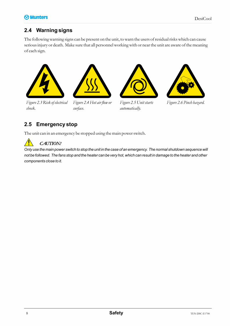
2.4 WarningsignsThe followingwarning signs can be present on the unit, towarn the users of residual riskswhich can causeserious injury or death. Make sure that all personnelworkingwith or near the unit are aware of themeaningof each sign.
Figure 2.3Risk of electricalshock.
Figure 2.4Hot air flow orsurface.
Figure 2.5Unit startsautomatically.
Figure 2.6 Pinch hazard.
2.5 EmergencystopThe unit can in an emergency be stopped using themain power switch.
CACACAUTION!UTION!UTION!Onlyuse themainpower switch to stop theunit in thecaseof anemergency. Thenormal shutdownsequencewillnot be followed. The fansstopand theheater canbeveryhot,which can result in damage to theheater andothercomponents close to it.
8 Safety TEN-DSC-E1708
DesiCool
3 Systemdesignand function
3.1 Main functionTheDesiCool™ air treatment system is a highly efficient energy recovery ventilation system. It uses lowcost or surplus heat to create amore comfortable indoor climate.TheDesiCool combinesMunters advanced desiccant dehumidification technologywith evaporativecooling.In summer the unit keeps the relative humidity in the room lower than a set summermaximumvalue, andalso controls the supply temperature to the set value.Inwinter the unit keeps the supply temperature at the set value by recovering heat from the exhaust air, whileat the same time controlling the roomhumidity not to be lower than aminimumset value.
3.2 Systemdesign
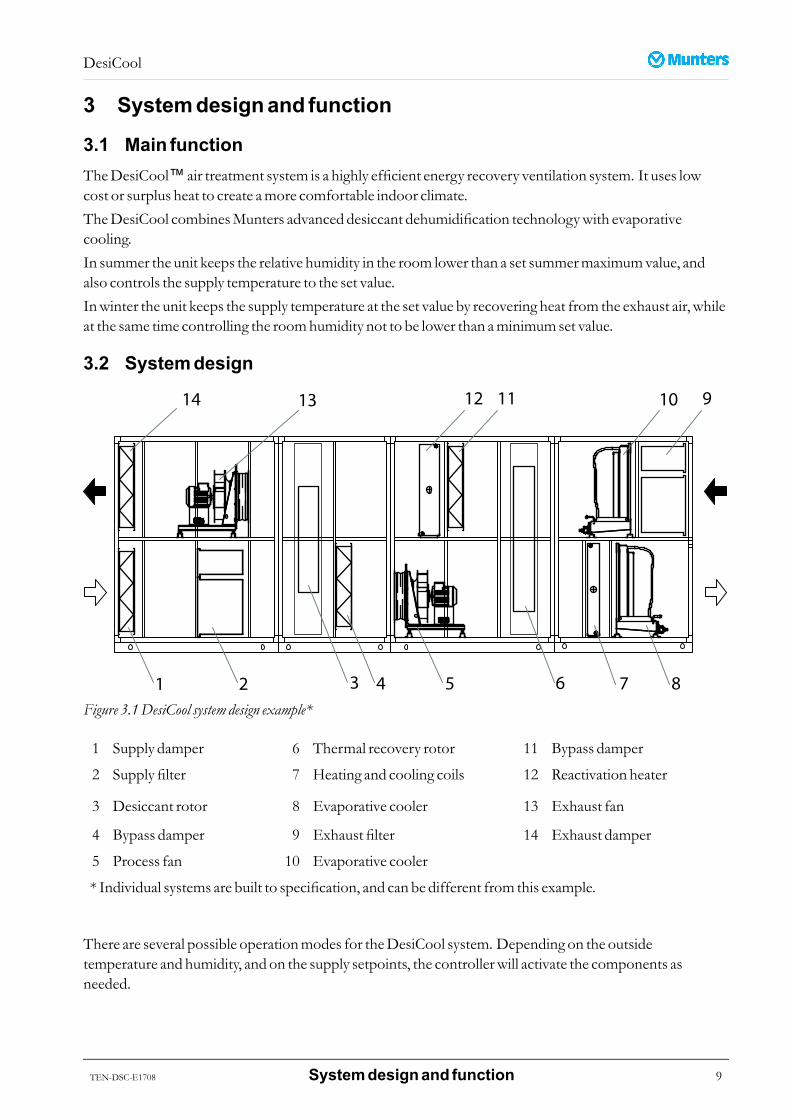
Figure 3.1DesiCool system design example*
1 Supply damper 6 Thermal recovery rotor 11 Bypass damper
2 Supply filter 7 Heating and cooling coils 12 Reactivation heater
3 Desiccant rotor 8 Evaporative cooler 13 Exhaust fan
4 Bypass damper 9 Exhaust filter 14 Exhaust damper
5 Process fan 10 Evaporative cooler
* Individual systems are built to specification, and can be different from this example.
There are several possible operationmodes for theDesiCool system. Depending on the outsidetemperature and humidity, and on the supply setpoints, the controllerwill activate the components asneeded.
TEN-DSC-E1708 Systemdesignand function 9
DesiCool
In summer time the unit produces cool and dehumidified air by a desiccant cooling process. The ambient airis dehumidified in the desiccant rotor. This process increases the air temperature. In the thermal recoveryrotor the air is indirectly cooled by the evaporative cooler in the exhaust. Finally, the air is further cooleddirectly by the evaporative cooler in the supply.There is a heater in the exhaust air stream for reactivation of the desiccant rotor. See themore detaileddescription in section 4.1,Desiccant rotor.Inwinter time the unit produceswarm air. The thermal recovery rotor starts to rotate and recovers heatfrom the exhaust air stream. Ifmore heat recovery is required the desiccant rotor also starts to rotate andrecovers both heat andmoisture. At extreme ambientwinter conditions the hotwater coil in the supply isalso in operation.Through the use of bypass dampers it is possible to optimize theway the air is treated.
10 Systemdesignand function TEN-DSC-E1708
DesiCool
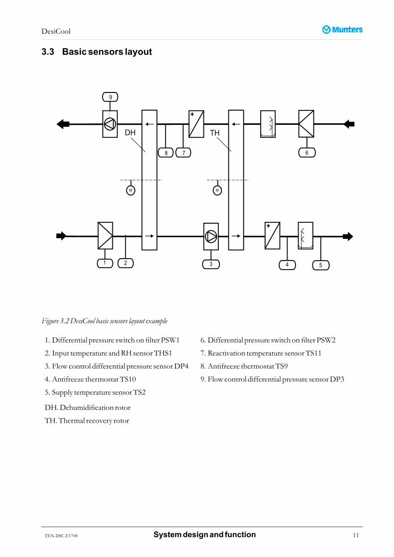
3.3 Basicsensors layout
Figure 3.2DesiCool basic sensors layout example
1. Differential pressure switch onfilter PSW1 6. Differential pressure switch onfilter PSW2
2. Input temperature andRHsensorTHS1 7. Reactivation temperature sensorTS11
3. Flow control differential pressure sensorDP4 8. Antifreeze thermostat TS9
4. Antifreeze thermostat TS10 9. Flow control differential pressure sensorDP3
5. Supply temperature sensorTS2
DH.Dehumidification rotor
TH.Thermal recovery rotor
TEN-DSC-E1708 Systemdesignand function 11
DesiCool
3.4 Pre- andpost-treatmentPre- and post-treatment of the process air can be performedby the following functional components:■ Inlet dampers to enable isolation of the unit from the air flow. The dampers are installed on the outside
of the unit.■ Heating coil: The coil can be electric or use hotwater or steam as heatingmedium. The coilmust then
be connected to an external heatingmedium supply. It is possible to activate a pump from the controlsystem.
■ Cooling coil: The coil uses chilledwater, possiblymixedwith glycol. The coilmust be connected to anexternalmedium supply. The control system regulates an actuator tomaintain dewpoint and or coolingsetpoint. It is possible to activate a pump and/or a chiller from the control system.
■ Filters for various air quality specifications. Filters can be equippedwith pressure drop sensors to enable"blockedfilter" alarm (option).
CACACAUTION!UTION!UTION!Coilsmust be frost protectedwhen there is a riskof frost. Seesection4.3.3, Frost protection.
12 Systemdesignand function TEN-DSC-E1708
DesiCool
4 MaincomponentsdescriptionNOTE!Somecomponentsareoptional, and individual systemspecificationsmaydiffer.All component picturesareexamples, andmaynot correspond to individual units.
4.1 Desiccant rotor
4.1.1 Function
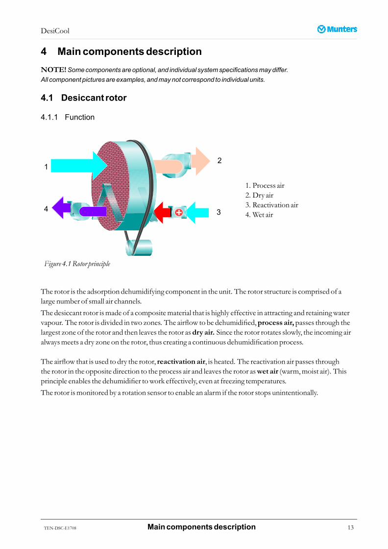
Figure 4.1Rotor principle
1. Process air2. Dry air3. Reactivation air4. Wet air
The rotor is the adsorption dehumidifying component in the unit. The rotor structure is comprised of alarge number of small air channels.The desiccant rotor ismade of a compositematerial that is highly effective in attracting and retainingwatervapour. The rotor is divided in two zones. The airflow to be dehumidified,process air,passes through thelargest zone of the rotor and then leaves the rotor asdry air. Since the rotor rotates slowly, the incoming airalwaysmeets a dry zone on the rotor, thus creating a continuous dehumidification process.
The airflow that is used to dry the rotor, reactivation air, is heated. The reactivation air passes throughthe rotor in the opposite direction to the process air and leaves the rotor aswet air (warm,moist air). Thisprinciple enables the dehumidifier towork effectively, even at freezing temperatures.The rotor ismonitored by a rotation sensor to enable an alarm if the rotor stops unintentionally.
TEN-DSC-E1708 Maincomponentsdescription 13
DesiCool
4.1.2 Rotormaintenance
The rotor surfacemust be inspected regularly. Performpressure dropmeasurements to follow rotor aging.The desiccant rotorwill not be replaced preventively, capacitymonitoringwill indicatewhen rotorreplacement is necessary.
4.1.3 Rotor seals , drivebelt anddrivemotor
The rotor drivemotor, drive belt and seals should be replaced if necessary, or at themaximum intervalsaccording to themaintenance schedule.Belt tension can be adjusted by shortening the belt.Rotor sealsmust be checked and adjusted once per year.
14 Maincomponentsdescription TEN-DSC-E1708

DesiCool
4.2 Thermal recovery rotor
4.2.1 Function
Figure 4.2 Thermal recovery rotor
The thermal rotor is, depending on the ambient conditions, used either for cooling or for heating of thesupply air. This is done by exchanging heat between the supply air streampassing through the lower half ofthe rotor, and the exhaust air streampassing through the top half in the opposite directionwhile the rotorrotates.The thermal rotor ismanufactured fromaluminiumwithmany small channels throughwhich the air passes,making a large contact surface to transfer the heat.The rotor is driven by an electricmotor and a drive belt around the circumference of the rotor.
4.2.2 Rotor
The rotor surfacemust be inspected regularly.If the rotor is dirty it can be cleanedwith a vacuumcleaner, orwith lowpressure compressed air if necessary.
4.2.3 Rotor seals , drivebelt anddrivemotor
The drive beltmust be checked after the first 100 hours of operation.The rotor drivemotor, drive belt and seals should be replaced if necessary, or at themaximum intervalsaccording to themaintenance schedule.Belt tension can be adjusted by shortening the belt.The clearance between the rotor surface and the sealsmust be checked during inspection. Adjust the seals ifnecessary.
TEN-DSC-E1708 Maincomponentsdescription 15
DesiCool
4.3 Watercoils
4.3.1 Cooling coils
Cooling can be supplied by optional coldwater coils installed in the pre- and or post-treatment sections.The coil uses chilledwater, possiblymixedwith glycol, as coolingmedium. The coilmust be connectedto an externalmedium supply.
CACACAUTION!UTION!UTION!Hotandcoldwater supply linesmust only bedesignedandexecutedbyqualifiedpersonnel taking intoaccountthe respective relevant local regulations.
When there is a riskof frost, thewater coilsmust be frost protected. Seesection4.3.3, Frost protection.
4.3.2 Heating coils
Heating can be supplied by optional hotwater coils installed in the pre- and or post-treatment section.The coil uses hotwater or steam as heatingmedium. The coilmust be connected to an external heatingmedium supply.
CACACAUTION!UTION!UTION!Hotandcoldwater supply linesmust only bedesignedandexecutedbyqualifiedpersonnel taking intoaccountthe respective relevant local regulations.
When there is a riskof frost, thewater coilsmust be frost protected. Seesection4.3.3, Frost protection.
4.3.3 Frost protection
If thewater in a coil freezes this could cause serious damage. A frozen coilmust almost always be replaced.The guarantee is no longer valid even if the cracks are not visible.If there is a risk of frost, the coolingmediummust be enrichedwith glycol or an anti-freeze heater completewith anti-freeze thermostatmust be installed.
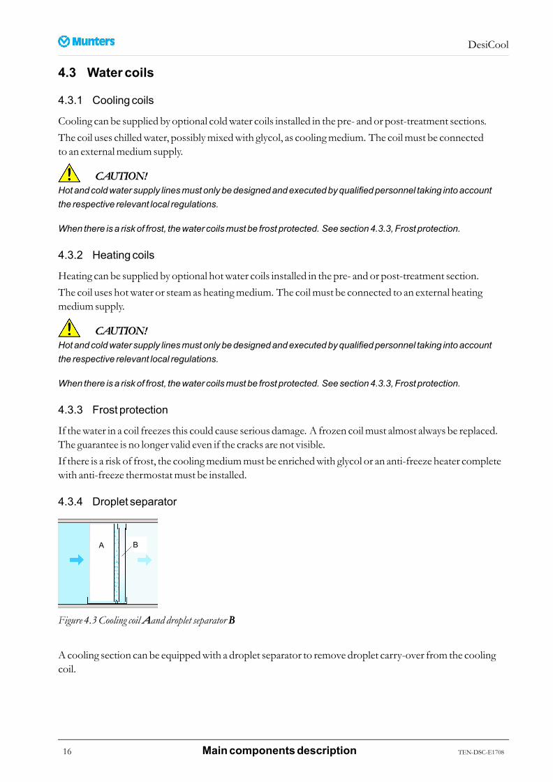
4.3.4 Droplet separator
Figure 4.3Cooling coilAAAand droplet separator BBB
Acooling section can be equippedwith a droplet separator to remove droplet carry-over from the coolingcoil.
16 Maincomponentsdescription TEN-DSC-E1708
DesiCool
The droplet separator is built from apatented three-plane-fluted pad that is set at an angle to the flowof air.The separator absorbs thewater droplets and transports themdown through thematerial to the drainagesection.
4.3.5 Cleaning
WWWARNING!ARNING!ARNING!Coil finshavesharpedges. Alwayswearprotectivegloveswhenworkingwith coils.
1. The coils should be checked at least once a year, and cleaned if required.2. Someof the dustwhich passes through the filters comes to rest on the coil cells. This layer of dust
affects the air flow and reduces the rate of exchange leading to decreased unit efficiency.3. The coils should therefore be kept clean. Cleaning can be done by using a vacuumcleaner, lowpressure
compressed air or lowpressurewater and a soft brush. Donot forget to clean the unit internally after thecoil cleaning. Never useHP cleaners, thiswill damage the coil fins.
4. Furthermore, in the case of cooling coils, clean the drip tray and siphon for the condensationwater onceper year. Note that siphons need to be refilledwithwater after thewinter season.
4.3.6 Stoppingwater flow to thecoils
Precautions to take in case of frost risk:- where it is envisaged to stop or considerably reduce the flowof hotwater, all the fresh air intakesmust
be closed and the ventilation stopped.- the reference point of the antifreeze thermostatmust not be set too low.- if forwhatever reason a building is not heated inwinter, the coils aswell as the pipingmust be emptied.Hotwater coilsMake sure that the temperature of the hotwater is not too low, and that the circulation of thewater ismaintained. Ensure that:■ the valves are open.■ the piping is purged from remaining gases.■ the hotwater circulation pumpoperates even at night.Cooling coilsCooling coilsmust be purged if the passing air temperature is lower than the freezing point of the coolant.Where the coils are suppliedwithwaterwhich does not contain glycol, and nopreheater coil is installed, it istherefore necessary to empty the coils as soon as the passing air temperature reaches 0 °C.
TEN-DSC-E1708 Maincomponentsdescription 17
DesiCool
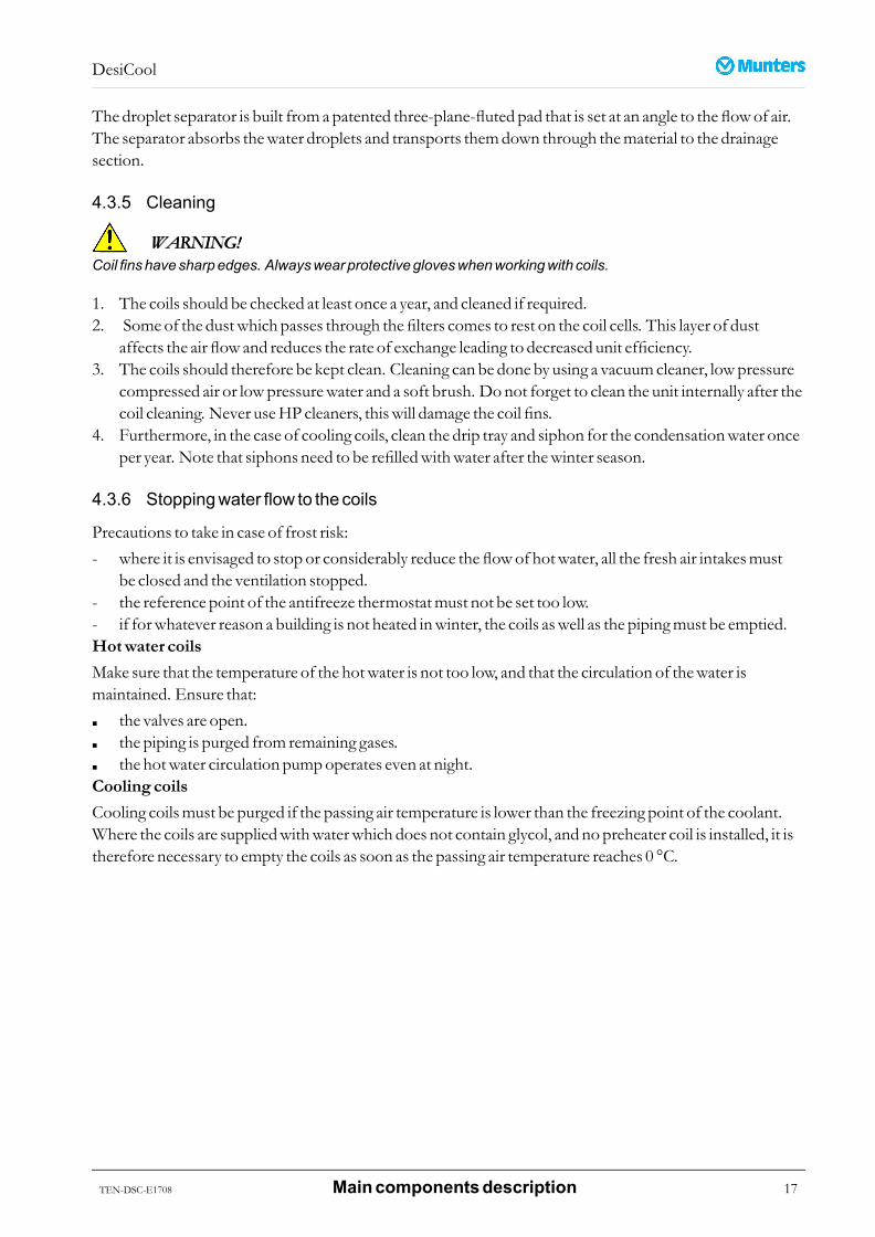
4.4 Evaporativecoolers/humidifiers
Evaporative coolers/humidifiers are placed both in the supply and exhaust air streams.They can have either a directwater supply, or a recirculated system.The heart of the FA6 cooler/humidifier is a cassettemade from inorganic evaporativemedia –GLASdek®.Water is supplied to the top of the evaporativemedia via a distribution header. Thewater flows downthe corrugated surface of themedia. As thewarm anddry air passes through themedia it evaporates aproportion of thewater and thus produces cool, humidified air. The rest of thewater assists inwashing themedia, and is drained back to the tank. In the case of a recirculated system, theremust be a bleed-off and anautomatic drainage in order to avoid contamination of thewater.The energy that is needed for the evaporation is taken from the air itself. The air that leaves the humidifier istherefore humidified and cooled simultaneouslywithout any external energy supply for the evaporation.This is in essence the adiabatic cooling process. It is very efficient and the consumption of energy is very low.Periodicmaintenanceof the coolers is recommendedonce a year, following the operating season.
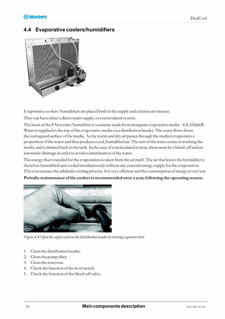
Figure 4.4Open the safety catch on the distribution header by turning a quarter turn
1. Clean the distribution header.2. Clean the pumpfilter.3. Clean the reservoir.4. Check the function of the level switch.5. Check the function of the bleed-off valve.
18 Maincomponentsdescription TEN-DSC-E1708
DesiCool
6. Check that the humidifier cassette is evenlywetted and that no calcium streaks can be foundon theinlet side.
7. Check that the hoses and couplings do not leak.8. Check the discharge pipe andwater trap. Clean if necessary.
NOTE!Formore informationonservicingof evaporative coolers/humidifiers, see theseparateMuntersFA6manual.
TEN-DSC-E1708 Maincomponentsdescription 19

DesiCool
4.5 Fans
4.5.1 Fan types
Figure 4.5 Plug fan Figure 4.6 Scroll fan
The unit can be equippedwith plug fans or scroll fans. The fans are driven by electricmotors that can becontrolled by frequency converters, which enable adjustment of the air pressure and air flow from theoperator panel.
4.5.2 Maintenance
1. Before starting up the unit, ensure that there are no loose objects inside the unit.2. Clean the inside of the unit using a vacuumcleaner.3. If the fan impellers come into contactwith contaminated air or dust, it is imperative that they are cleaned
regularly to avoid vibrations caused by unbalance.4. Donot use any aggressive cleaning agents, clean fan housingwithwarmwater if required.5. Never use a high pressure cleaner orwater spray for cleaning.
4.6 Filters
4.6.1 Filter types
Figure 4.7 Bag filter Figure 4.8 Panel filters
20 Maincomponentsdescription TEN-DSC-E1708

DesiCool
4.6.2 Filtermaintenance
WWWARNING!ARNING!ARNING!There is a firehazard, or riskof unitmalfunction, if filters aremaintained insufficiently or incorrectly.
WWWARNING!ARNING!ARNING!When replacing thefilters orworking inadustyarea: Toprotect theuser fromdust,wear a suitableCEmarked facemaskselectedandfitted inaccordancewith theapplicable safety standards.
Thefilters require regular replacement. The frequency depends on the amount of dust in the air and theoperating conditions. Afilter guardwill indicatewhen replacement is required (option).Blockedfilters can reduce the air flow in the unit. Replacing the filters is therefore of prime importance forthe correct operation of the installation. Incorrect air flowwill reduce the capacity and the energy efficiencyof the unit. Replace the filterswhen:■ Final pressure drop is reached.■ There is a filter alarm.■ Thefilter is damaged and air is passingwithout filtration.■ Paper framefilters have becomewet.
4.6.3 Panel filters
■ Check the degree of dirt accumulation bymeasuring the differential pressure or by inspecting the filtersvisually.
■ Replace as required.■ Before replacing the filter, check that the frames are sealed and if necessary replace the seals.■ Clean the filter section, check that there is no dirt beyond the filter.
4.6.4 Bagfilters
■ Check the degree of dirt accumulation bymeasuring the differential pressure or by inspecting the filtersvisually. Bag filters cannot be cleaned and are not reusable.
■ Fit a newbag filter and check its tightness. Bagsmust be verticallymounted.
TEN-DSC-E1708 Maincomponentsdescription 21

DesiCool
4.7 Dampers
Figure 4.9 Inlet damper
Dampers are used to open and close the inlet and the outlet of the unit, aswell as optionally for controllingbypass and recirculation.
WWWARNING!ARNING!ARNING!Keephandsclear of thedamperswhen theyaremoving. Riskof personal injury.
Openingswithdampers shouldalwaysbecoveredbyducts.
Anyunductedair dampers shouldbefittedwithaprotectivegrille (not included inMuntersdelivery) topreventinjury from thedamperblademovement.
DampermaintenanceClean and check the operation of the dampers, the gearing and bearings.The blades can be cleanedwithwater or compressed air.Check the position in respect of the indications “OPEN” and “CLOSED”.If the dampers do notmove freely, lubricate the gearing and bearingswith silicone oil.
22 Maincomponentsdescription TEN-DSC-E1708
DesiCool
4.8 Flexibleconnections
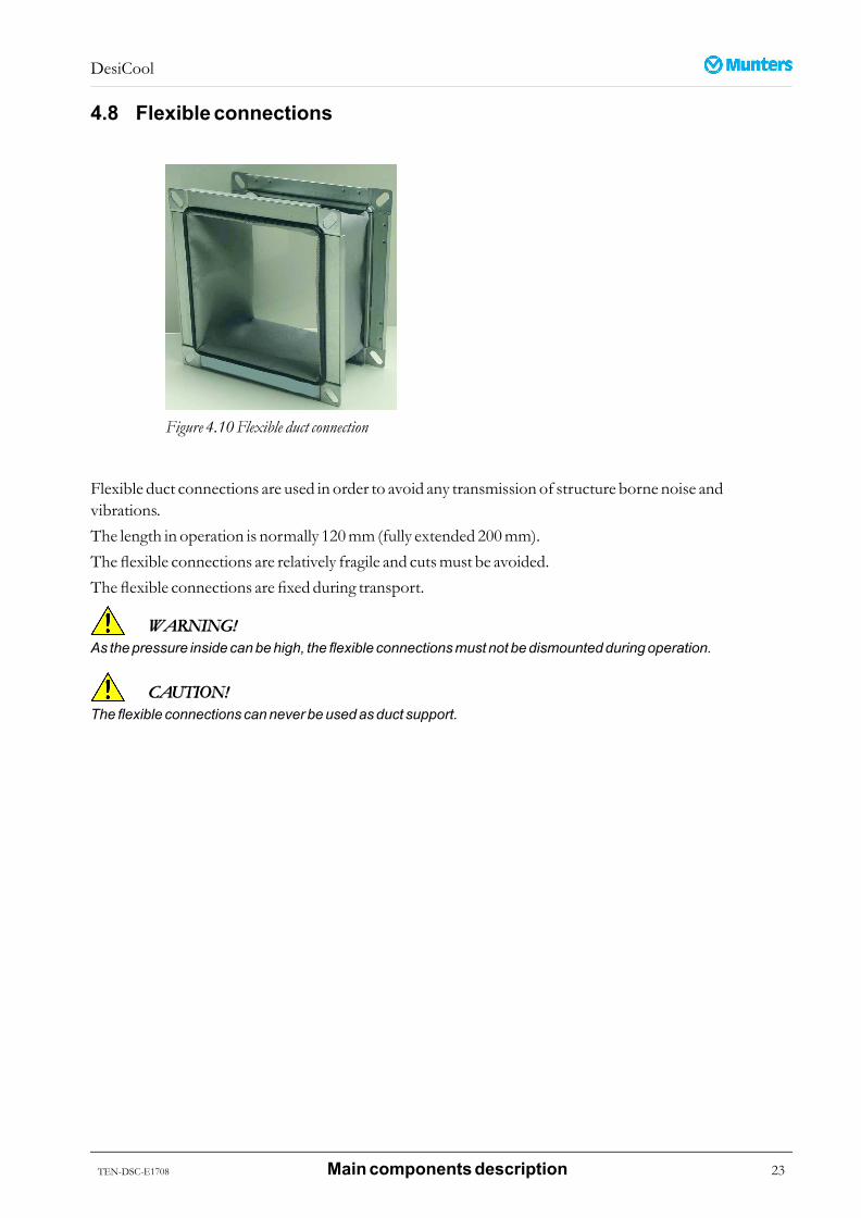
Figure 4.10Flexible duct connection
Flexible duct connections are used in order to avoid any transmission of structure borne noise andvibrations.The length in operation is normally 120mm (fully extended 200mm).The flexible connections are relatively fragile and cutsmust be avoided.The flexible connections are fixed during transport.
WWWARNING!ARNING!ARNING!As thepressure insidecanbehigh, theflexible connectionsmust not bedismountedduringoperation.
CACACAUTION!UTION!UTION!Theflexible connections cannever beusedasduct support.
TEN-DSC-E1708 Maincomponentsdescription 23

DesiCool
5 Commissioning
CACACAUTION!UTION!UTION!Commissioningand initial start-upof theunit shouldbecarriedout byMunterspersonnel only.
5.1 Checksbeforestartingup- Check that the fanmotor transportation blocks are removed.- It is always possible that during transport certain elementswork loose due to vibrations. We advise you
to check thoroughly that all screws and nuts, and in particular rotating parts such as turbines, pulleys,bearings, etc., are tight.
- Turn the fan by hand tomake sure that it can rotate freely. Check that no foreign bodies have foundtheir way into the fan.
- Check that the bearings in themotor and fan are properly lubricated.- Check that there are no foreign bodies in the unit (or in the ducts) and that the air intakes and outlets
are not blocked.- Checkmanually that the dampers are correctly positioned and are able to operate correctly.- Check the tension and alignment of the belts and readjust if necessary.- Check all electrical connections.- Check the direction of rotation of the fans and compressors. Correct direction can be checked on a fan
wheelwith an arrow, or bymonitoring the change in high and lowpressurewhen a compressor starts.
CACACAUTION!UTION!UTION!Rotationdirection is checked in the factorymeaning that if onemotor is rotating in thewrongdirection, allmotorsareactually rotating in thewrongdirection. Phasesmust thenbe invertedon themain terminal block. It is stillimportant to checkallmotors.
- The cooling coil sections are suppliedwith drains. Check that they are correctly connected to allowefficient drainage.
- Fit the air filters. Ensure that the filters are firmly attached to the frame.
NOTE!Beforeputting theunit intooperation, thebagfiltersmust beprotected toavoid theexcessiveaccumulationof dirt causedby thefirst use (dust andconstruction residue in theunit).
- Adjust the differential pressure switches.
5.2 Inspectionofevaporativecoolers1. Remove any loosematerial in the bottomof thewater tank.2. Close the bottomvalve andfill the tankwithwater.3. Check that the connections are tight.4. Check the function of each solenoid valve.
24 Commissioning TEN-DSC-E1708
DesiCool
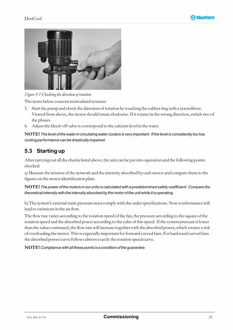
Figure 5.1Checking the direction of rotationThe items below concern recirculated systems:5. Start the pump and check the direction of rotation by touching the rubber ringwith a screwdriver.
Viewed fromabove, themotor should rotate clockwise. If it rotates in thewrong direction, switch twoofthe phases.
6. Adjust the bleed-off valve to correspond to the calcium level in thewater.
NOTE!The level of thewater in circulatingwater coolers is very important. If the level is consistently too low,coolingperformancecanbedrastically impaired.
5.3 StartingupAfter carrying out all the checks listed above, the unit can be put into operation and the following pointschecked:a)Measure the tension of the network and the intensity absorbed by eachmotor and compare them to thefigures on themotor identification plate.
NOTE!Thepowerof themotors inour units is calculatedwithapredeterminedsafety coefficient. Compare thetheoretical intensitywith the intensity absorbedby themotor of theunitwhile it is operating.
b)The system’s external static pressuremust complywith the order specifications. Non-conformancewilllead to variations in the air flow.Theflow rate varies according to the rotation speed of the fan, the pressure according to the square of therotation speed and the absorbed power according to the cube of this speed. If the systempressure is lowerthan the values estimated, the flow ratewill increase togetherwith the absorbed power, which creates a riskof overloading themotor. This is especially important for forward curved fans. For backward curved fansthe absorbed power curve follows almost exactly the rotation speed curve.
NOTE!Compliancewithall thesepoints is a conditionof theguarantee.
TEN-DSC-E1708 Commissioning 25
DesiCool
6 Serviceandmaintenance
6.1 Safety
Figure 6.1Electrical hazard Figure 6.2 Secure against reconnection
Electrical hazard
WWWARNING!ARNING!ARNING!Installation, adjustments,maintenanceand repairsmust only becarriedout byqualifiedpersonnelwhoareawareof the risks involvedwhenworkingwithequipment operatingwithhighelectrical voltageandhighmachinetemperatures.
WWWARNING!ARNING!ARNING!Donot opendistributionboxesor other electrical connectionboxes. Theunit is connected tohighvoltagewhichcancauseserious injuryor death.
WWWARNING!ARNING!ARNING!Beforedoinganyserviceormaintenanceworkon theunitmakesure that all electrical equipment is disconnectedfrom thepower supply, andsecuredagainst reconnection.
WWWARNING!ARNING!ARNING!Anyexternal electrical equipment, for exampleaportable lamp,must beconnected toanearth fault breaker.
26 Serviceandmaintenance TEN-DSC-E1708

DesiCool
Physical hazard
WWWARNING!ARNING!ARNING!Removehandwheels fromwater andsteamsupply valves, or otherwise lockoff reopeningonacomponent thatis isolated toprevent inadvertent reopening. Alternatively, placeanoticeon thevalve indicating that it is closedfor a reason.
WWWARNING!ARNING!ARNING!Rotatinghazard. Theunit contains rotating fansandothermovingparts.
Toprevent personal injury, theunitmust be runwithall panel doors closedandall removablepanels andprotectivegridsproperly in place. Never open thedoorsor panels beforeall fansandothermovingparts havecome toacomplete stop, and themainpower is switchedoff.
Fansandothermovingparts canstart automatically andwithoutwarning.
WWWARNING!ARNING!ARNING!Cleaningagents, coolingmedia, oil andgreaseare substances that aredangerous topersonal health and to theenvironment. Theymust not beallowed todrainaway into thesoil or thepublic sewer system. Thedisposal of suchsubstancesmust beeffected inaccordancewith local andnational lawand regulations.
NOTE!Aportable lamp is requiredwhencarryingout servicework inside theunit.
Property hazard
CACACAUTION!UTION!UTION!Serviceandmaintenancework shouldonly becarriedout byqualifiedand trainedpersonnel. Operating faults canoccur if theunit ismaintained insufficiently or incorrectly.
CACACAUTION!UTION!UTION!Protect thebottompanels ifworkmust becarriedout inside theunit.
TEN-DSC-E1708 Serviceandmaintenance 27
DesiCool
6.2 GeneralMost air treatment units require the same type ofmaintenance. The following paragraphs explain thenecessary basic rules.Service andmaintenance interval lengths are primarily determined by operating conditions and theenvironment inwhich the unit is installed. For example, if the process air contains a lot of dust, preventativemaintenance should be carried out at shorter intervals. The same also applies if the unit works intensively.The service levels for a standard service andmaintenance programme are described in section6.3, Service options.The control system is equippedwith a service indicator. It is programmed at commissioning to give a servicealarm after an estimated number of operating hours, or on the preset date for the next service.
6.3 ServiceoptionsIn addition to commissioning of the unit there are four service options (A -D) as standard.S. Commissioning/start-up.A. Inspection and if necessary change of filter. General function check.B. In addition toA, safety check and capacity, temperature and humidity regulationmeasurements.C. In addition toB, preventive replacement of some components after 3 years of operation.D. In addition toC, preventive replacement of some components after 6 years of operation.
NOTE!AlwayscontactMunters for serviceor repair. Operating faults canoccur if theunit ismaintainedinsufficiently or incorrectly.
NOTE!Commissioning/Start-up inspection "S"byMunters ismandatory to validate the fullwarranty.
Munters service engineershave special equipment and rapid spare parts access to handle service on allMunters products. All test equipment used by our personnel to ensure proper systembalancing is certifiedfor accuracy.Munters Service can offer a service plan adapted to suit the conditions of a specific installation. See contactaddresses on the back page of thismanual.
6.4 ExtendedwarrantyMunters offers an extendedwarranty to the standard termswhen theCustomer signs a service contractwithMunters. Details are available on request.
28 Serviceandmaintenance TEN-DSC-E1708
DesiCool
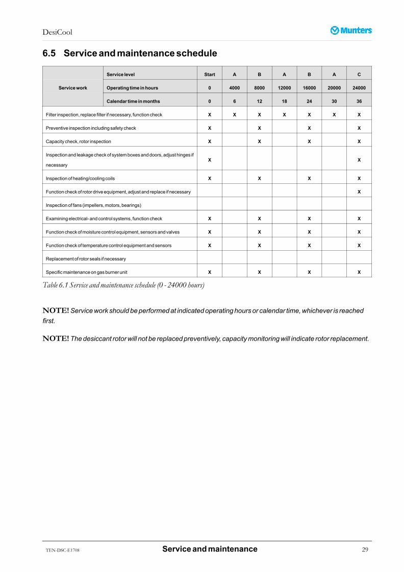
6.5 Serviceandmaintenanceschedule
Service level Start A B A B A C
Operating time inhours 0 4000 8000 12000 16000 20000 24000Servicework
Calendar time inmonths 0 6 12 18 24 30 36
Filter inspection, replacefilter if necessary, function check X X X X X X X
Preventive inspection includingsafety check X X X X
Capacity check, rotor inspection X X X X
Inspectionand leakagecheckof systemboxesanddoors, adjust hinges if
necessaryX X
Inspectionof heating/cooling coils X X X X
Function checkof rotor driveequipment, adjust and replace if necessary X
Inspectionof fans (impellers,motors, bearings)
Examiningelectrical- andcontrol systems, function check X X X X
Function checkofmoisture control equipment, sensorsandvalves X X X X
Function checkof temperature control equipment andsensors X X X X
Replacement of rotor seals if necessary
Specificmaintenanceongasburner unit X X X X
Table 6.1 Service andmaintenance schedule (0 - 24000 hours)
NOTE!Servicework shouldbeperformedat indicatedoperatinghoursor calendar time,whichever is reachedfirst.
NOTE!Thedesiccant rotorwill not be replacedpreventively, capacitymonitoringwill indicate rotor replacement.
TEN-DSC-E1708 Serviceandmaintenance 29

DesiCool
Service level A B A B A D
Operating time inhours 28000 32000 36000 40000 44000 48000Servicework
Calendar time inmonths 42 48 54 60 66 72
Filter inspection, replacefilter if necessary, function check X X X X X X
Preventive inspection includingsafety check X X X
Capacity check, rotor inspection X X X
Inspectionand leakagecheckof systemboxesanddoors, adjust hinges
if necessaryX
Inspectionof heating/cooling coils X X X
Function checkof rotor driveequipment, adjust and replace if necessary X
Inspectionof fans (impellers,motors, bearings) X
Examiningelectrical- andcontrol systems, function check X X X
Function checkofmoisture control equipment, sensorsandvalves X X X
Function checkof temperature control equipment andsensors X X X
Replacement of rotor seals if necessary X
Specificmaintenanceongasburner unit X X X
Table 6.2 Service andmaintenance schedule (28000 - 48000 hours)
NOTE!Maintenanceschedule restarts againaftermaintenance typeD.
30 Serviceandmaintenance TEN-DSC-E1708
DesiCool
7 ScrappingThe unitmust be scrapped in accordancewith applicable legal requirements and regulations. Contact yourlocal authorities.The rotormaterial is not combustible, and should be deposited like glass fibrematerials.If the rotor has been exposed to chemicals that are dangerous to the environment the riskmust be assessed.The chemicals can accumulate in the rotormaterial. Take the necessary precautions to complywithapplicable legal requirements and regulations.
WWWARNING!ARNING!ARNING!If the rotor is tobecut in pieces,wearasuitableCEmarked facemaskselectedandfitted inaccordancewith theapplicable safety standards toprotect from thedust.
TEN-DSC-E1708 Scrapping 31
DesiCool
8 SupplementsAdditional information is available in supplements as applicable:■ Product specification data sheet■ Control system■ Installation■ Humidification
32 Supplements TEN-DSC-E1708
DesiCool
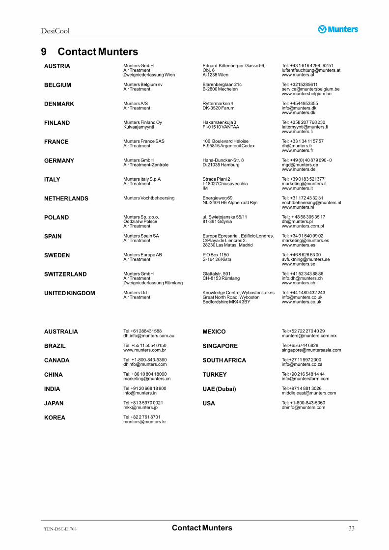
9 ContactMuntersAUSTRIA MuntersGmbH
AirTreatmentZweigniederlassungWien
Eduard-Kittenberger-Gasse56,Obj. 6A-1235Wien
Tel: +4316164298–[email protected]
BELGIUM MuntersBelgiumnvAir Treatment
Blarenberglaan21cB-2800Mechelen
Tel: [email protected]
DENMARK MuntersA/SAir Treatment
Ryttermarken4DK-3520Farum
Tel: [email protected]
FINLAND MuntersFinlandOyKuivaajamyynti
Hakamäenkuja3FI-01510VANTAA
Tel: [email protected]
FRANCE MuntersFranceSASAir Treatment
106,BoulevardHéloiseF-95815ArgenteuilCedex
Tel: [email protected]
GERMANY MuntersGmbHAirTreatment-Zentrale
Hans-Duncker-Str. 8D-21035Hamburg
Tel: +49 (0) 40879690 [email protected]
ITALY Munters ItalyS.p.AAir Treatment
StradaPiani 2I-18027ChiusavecchiaIM
Tel: [email protected]
NETHERLANDS MuntersVochtbeheersing Energieweg69NL-2404HEAlphena/dRijn
Tel: [email protected]
POLAND MuntersSp. zo.o.OddzialwPolsceAir Treatment
ul. Swietojanska55/1181-391Gdynia
Tel.: [email protected]
SPAIN MuntersSpainSAAir Treatment
EuropaEpresarial. EdificioLondres.C/PlayadeLiencres2.28230LasMatas. Madrid
Tel: [email protected]
SWEDEN MuntersEuropeABAir Treatment
POBox1150S-16426Kista
Tel: [email protected]
SWITZERLAND MuntersGmbHAirTreatmentZweigniederlassungRümlang
Glattalstr. 501CH-8153Rümlang
Tel: [email protected]
UNITEDKINGDOM MuntersLtdAir Treatment
KnowledgeCentre,WybostonLakesGreatNorthRoad,WybostonBedfordshireMK443BY
Tel: [email protected]
AUSTRALIA Tel:[email protected]
MEXICO Tel:[email protected]
BRAZIL Tel: +551150540150www.munters.com.br
SINGAPORE Tel:[email protected]
CANADA Tel: [email protected]
SOUTHAFRICA Tel:[email protected]
CHINA Tel: [email protected]
TURKEY Tel:[email protected]
INDIA Tel:[email protected]
UAE(Dubai) Tel:[email protected]
JAPAN Tel:[email protected]
USA Tel: [email protected]
KOREA Tel:[email protected]
TEN-DSC-E1708 ContactMunters 33

www.munters.com