Embed Size (px)
Citation preview
®
™
Air
Ch
ain
Ho
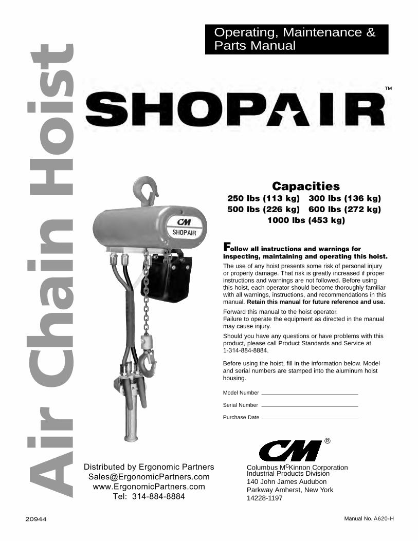
ist Operating, Maintenance &
Parts Manual
The use of any hoist presents some risk of personal injury or property damage. That risk is greatly increased if proper instructions and warnings are not followed. Before using this hoist, each operator should become thoroughly familiar with all warnings, instructions, and recommendations in this manual. Retain this manual for future reference and use.Forward this manual to the hoist operator.Failure to operate the equipment as directed in the manual may cause injury.Should you have any questions or have problems with this product, please call Product Standards and Service at1-314-884-8884.
Before using the hoist, fill in the information below. Model and serial numbers are stamped into the aluminum hoist housing.
Model Number
Serial Number
Purchase Date
Follow all instructions and warnings forinspecting, maintaining and operating this hoist.
Capacities250 lbs (113 kg) 300 lbs (136 kg)500 lbs (226 kg) 600 lbs (272 kg)
1000 lbs (453 kg)
Columbus McKinnon Corporation Industrial Products Division140 John James Audubon Parkway Amherst, New York 14228-1197
Manual No. A620-H20944
Distributed by Ergonomic [email protected]
www.ErgonomicPartners.comTel: 314-884-8884
®
Columbus McKinnon Corporation • Industrial Products Division • 140 John James Audubon Parkway Amherst, New York 14228-1197
Note: When ordering parts, always furnish Rated Load and Serial Number of hoist on which theparts are to be used.For the location of the nearest Repair Station, see the list located on the inside front cover.
LIMITATION OF WARRANTIES, REMEDIES AND DAMAGES
THE WARRANTY STATED BELOW IS GIVEN IN PLACE OF ALLOTHER WARRANTIES, EXPRESS OR IMPLIED, OFMERCHANTABILITY, FITNESS FOR A PARTICULAR PURPOSE,OR OTHERWISE, NO PROMISE OR AFFIRMATION OF FACTMADE BY ANY AGENT OR REPRESENTATIVE OF SELLERSHALL CONSTITUTE AWARRANTY BY SELLER OR GIVE RISETO ANY LIABILITY OR OBLIGATION.
Seller warrants that on the date of delivery to carrier the goodsare free from defects in workmanship and materials.
SELLER’S SOLE OBLIGATION IN THE EVENT OF BREACH OFWARRANTY OR CONTRACT OR FOR NEGLIGENCE OROTHERWISE WITH RESPECT TO GOODS SOLD SHALL BEEXCLUSIVELY LIMITED TO REPAIR OR REPLACEMENT,F.O.B. SELLER’S POINT OF SHIPMENT, OF ANY PARTSWHICH SELLER DETERMINES TO HAVE BEEN DEFECTIVEor if Seller determines that such repair or replacement is notfeasible, to a refund of the purchase price upon return of thegoods to Seller.
Any action against Seller for breach of warranty, negligence orotherwise, must be commenced within one year after such causeof action occurs.
NO CLAIM AGAINST SELLER FOR ANY DEFECT IN THEGOODS SHALL BE VALID OR ENFORCEABLE UNLESSBUYER’S WRITTEN NOTICE THEREOF IS RECEIVED BYSELLER WITHIN ONE YEAR FROM THE DATE OF SHIPMENT.Seller shall not be liable for any damage, injury or loss arisingout of the use of the goods if, prior to such damage, injury orloss, such goods are (1) damaged or misused following Seller’sdelivery to carrier; (2) not maintained, inspected, or used incompliance with applicable law and Seller’s written instructionsand recommendations; or (3) installed, repaired, altered ormodified without compliance with such law, instructions orrecommendations.
UNDER NO CIRCUMSTANCES SHALL SELLER BE LIABLEFOR INCIDENTAL OR CONSEQUENTIAL DAMAGES ASTHOSE TERMS ARE DEFINED IN SECTION 2-715 OF THEUNIFORM COMMERCIAL CODE.
INDEMNIFICATION AND SAFE OPERATIONBuyer shall comply with and require its employees to comply withdirections set forth in instructions and manuals furnished bySeller and shall use and require its employees to follow suchinstructions and manuals and to use reasonable care in the useand maintenance of the goods. Buyer shall not remove or permitanyone to remove any warning or instruction signs on the goods.In the event of personal injury or damage to property or businessarising from the use of the goods, Buyer shall within 48 hoursthereafter give Seller written notice of such injury or damage.Buyer shall cooperate with Seller in investigating any such injuryor damage and in the defense of any claims arising therefrom.
If Buyer fails to comply with this section or if any injury ordamage is caused, in whole or in part, by Buyer’s failure tocomply with applicable federal or state safety requirements,Buyer shall indemnify and hold Seller harmless against anyclaims, loss or expense for injury or damage arising from the useof the goods.
Alterations or modifications of equipment and use of non-factoryrepair parts can lead to dangerous operation and injury.
TO AVOID INJURY:• Do not alter or modify equipment.• Do use only factory replacement parts.
2008 Columbus McKinnon Corp. Printed in U.S.A. 8-1-0709/08
CM HOIST PARTS AND SERVICE ARE AVAILABLE IN THE UNITED STATES AND IN CANADA
As a CM Hoist user, you are assured of reliable repair and parts services through a network of Master Parts Depots and Service Centers that are strategically located in the United States and Canada. These facilities have been selected on the basis of their demonstrated ability to handle all parts and repair requirements promptly and efficiently.
Below is a list of the Master Parts Depots in the Unites States and Canada. To quickly obtain the name of the U.S. Service Center located nearest you, call (314) 884-8884.
UNITED STATES
MISSOURIDistributed by Ergonomic Partners*[email protected]: 314-884-8884
**ARE ALSO MASTER PARTS DEPOTS
**MASTER PARTS DEPOT ONLY
i
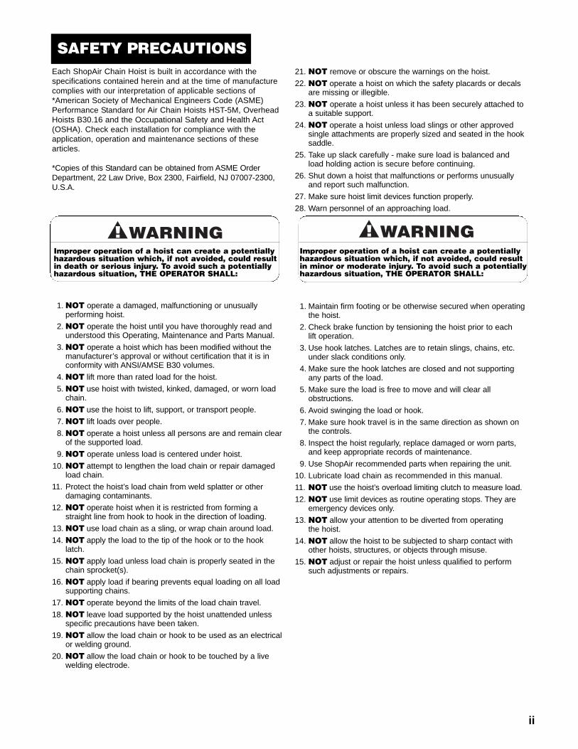
SAFETY PRECAUTIONSEach ShopAir Chain Hoist is built in accordance with thespecifications contained herein and at the time of manufacturecomplies with our interpretation of applicable sections of*American Society of Mechanical Engineers Code (ASME)Performance Standard for Air Chain Hoists HST-5M, OverheadHoists B30.16 and the Occupational Safety and Health Act(OSHA). Check each installation for compliance with theapplication, operation and maintenance sections of thesearticles.
*Copies of this Standard can be obtained from ASME OrderDepartment, 22 Law Drive, Box 2300, Fairfield, NJ 07007-2300,U.S.A.
1.NOT operate a damaged, malfunctioning or unusuallyperforming hoist.
2.NOT operate the hoist until you have thoroughly read andunderstood this Operating, Maintenance and Parts Manual.
3.NOT operate a hoist which has been modified without themanufacturer’s approval or without certification that it is inconformity with ANSI/AMSE B30 volumes.
4.NOT lift more than rated load for the hoist.5.NOT use hoist with twisted, kinked, damaged, or worn loadchain.
6.NOT use the hoist to lift, support, or transport people.7.NOT lift loads over people.8.NOT operate a hoist unless all persons are and remain clearof the supported load.
9.NOT operate unless load is centered under hoist.10.NOT attempt to lengthen the load chain or repair damaged
load chain.11. Protect the hoist’s load chain from weld splatter or other
damaging contaminants.12. NOT operate hoist when it is restricted from forming a
straight line from hook to hook in the direction of loading.13.NOT use load chain as a sling, or wrap chain around load.14. NOT apply the load to the tip of the hook or to the hook
latch.15. NOT apply load unless load chain is properly seated in the
chain sprocket(s).16. NOT apply load if bearing prevents equal loading on all load
supporting chains.17. NOT operate beyond the limits of the load chain travel.18. NOT leave load supported by the hoist unattended unless
specific precautions have been taken.19. NOT allow the load chain or hook to be used as an electrical
or welding ground.20. NOT allow the load chain or hook to be touched by a live
welding electrode.
21. NOT remove or obscure the warnings on the hoist.22. NOT operate a hoist on which the safety placards or decals
are missing or illegible.23. NOT operate a hoist unless it has been securely attached to
a suitable support.24. NOT operate a hoist unless load slings or other approved
single attachments are properly sized and seated in the hooksaddle.
25. Take up slack carefully - make sure load is balanced andload holding action is secure before continuing.
26. Shut down a hoist that malfunctions or performs unusuallyand report such malfunction.
27. Make sure hoist limit devices function properly.28. Warn personnel of an approaching load.
1. Maintain firm footing or be otherwise secured when operatingthe hoist.
2. Check brake function by tensioning the hoist prior to eachlift operation.
3. Use hook latches. Latches are to retain slings, chains, etc.under slack conditions only.
4. Make sure the hook latches are closed and not supportingany parts of the load.
5. Make sure the load is free to move and will clear allobstructions.
6. Avoid swinging the load or hook.7. Make sure hook travel is in the same direction as shown onthe controls.
8. Inspect the hoist regularly, replace damaged or worn parts,and keep appropriate records of maintenance.
9. Use ShopAir recommended parts when repairing the unit.10. Lubricate load chain as recommended in this manual.11. NOT use the hoist’s overload limiting clutch to measure load.12. NOT use limit devices as routine operating stops. They are
emergency devices only.13. NOT allow your attention to be diverted from operating
the hoist.14. NOT allow the hoist to be subjected to sharp contact with
other hoists, structures, or objects through misuse.15. NOT adjust or repair the hoist unless qualified to perform
such adjustments or repairs.
Improper operation of a hoist can create a potentiallyhazardous situation which, if not avoided, could resultin death or serious injury. To avoid such a potentiallyhazardous situation, THE OPERATOR SHALL:
Improper operation of a hoist can create a potentiallyhazardous situation which, if not avoided, could resultin minor or moderate injury. To avoid such a potentiallyhazardous situation, THE OPERATOR SHALL:
ii
iii
• Standard Protector™ overload device.• 10-pocket, oblique lay liftwheel provides longer chain life.• Epoxy powder coat finish.• Variable flow, two lever pendant for precise load spotting.• Threaded external exhaust for piping away exhaust inclean room or painting applications.
• Small, compact design for commercial & industrialapplications.
• Industrial duty air motor for tough applications.• Gear train is lifetime-lubricated with non-oxidizing grease.• Hardened forged steel, latch-type lower hook rotates3600.
• Hardened forged steel, rigid latch-type upper hook.• Rugged cast aluminum alloy hoist frame.• Alloy load chain.• Lifetime warranty against defects in materials andworkmanship.
• Made in USA.
Overloading and improper use can result in injury.
TO AVOID INJURY:• Do not exceed working load limit, load rating or capacity.• Do not use to lift people or loads over people.• Use only CM® alloy chain for overhead lifting.• Read and follow all instructions.
1
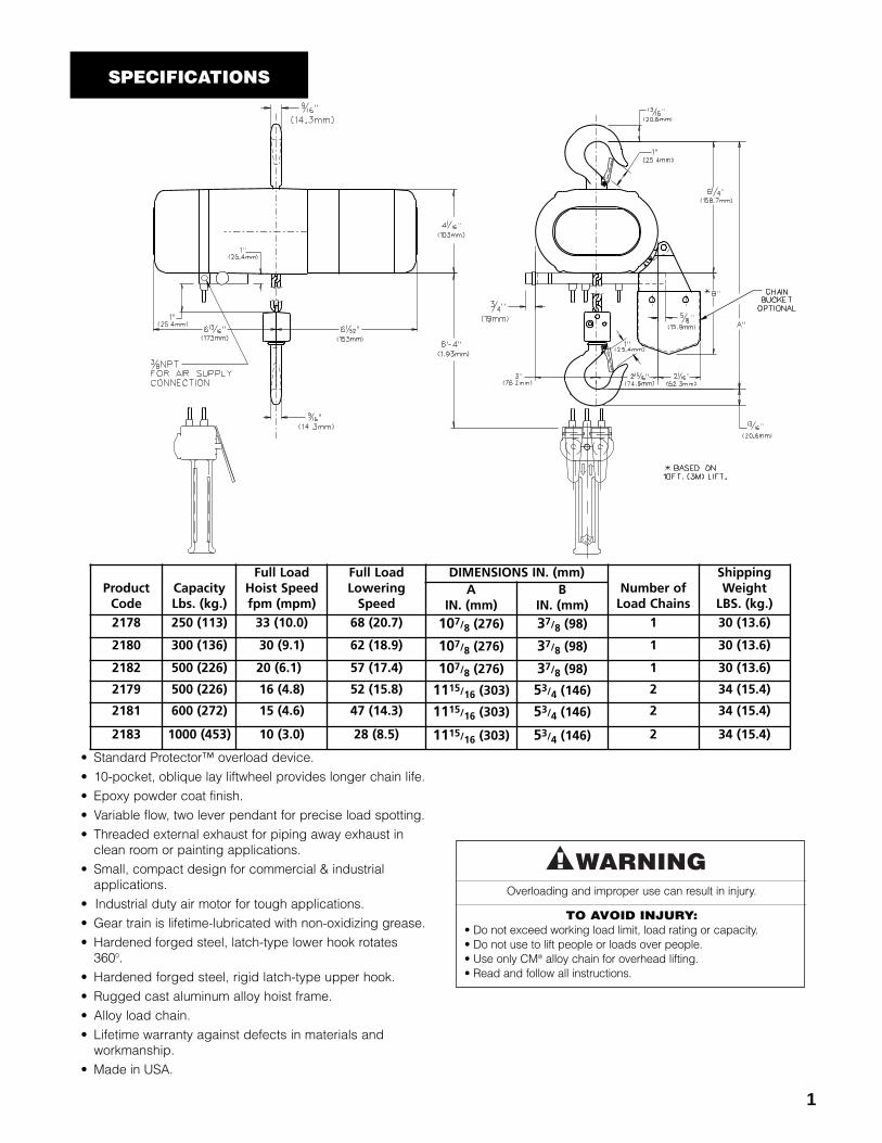
SPECIFICATIONS
ProductCode
CapacityLbs. (kg.)
Full LoadHoist Speedfpm (mpm)
Full LoadLoweringSpeed
DIMENSIONS IN. (mm)Number ofLoad Chains
ShippingWeightLBS. (kg.)
AIN. (mm)
BIN. (mm)
2178 250 (113) 33 (10.0) 68 (20.7) 107/8 (276) 37/8 (98) 1 30 (13.6)
2180 300 (136) 30 (9.1) 62 (18.9) 107/8 (276) 37/8 (98) 1 30 (13.6)
2182 500 (226) 20 (6.1)) 57 (17.4) 107/8 (276) 37/8 (98) 1 30 (13.6)
2179 500 (226) 16 (4.8) 52 (15.8) 1115/16 (303) 53/4 (146) 2 34 (15.4)
2181 600 (272) 15 (4.6) 47 (14.3) 1115/16 (303) 53/4 (146) 2 34 (15.4)
2183 1000 (453) 10 (3.0) 28 (8.5) 1115/16 (303) 53/4 (146) 2 34 (15.4)
2
The ShopAir Hoists are precision, air operated link type chainhoists that are available in five rated capacities: 250, 300, 500600 and 1000 pounds (113, 136, 226, 272 and 453 kg.). Eachunit is supplied with a pendant throttle control station forcontrolling the lifting and lowering speeds and an upper latchtype hook for suspending the hoist from a fixed support ortrolley.
The basic design of the ShopAir consists of a lightweight,rugged aluminum alloy frame which houses a vane type airmotor, hardened steel gears, hardened steel oblique layliftwheel, a disc type load brake and a muffler for quietoperation. The gearing includes a Protector™ that is afactory set clutch that prevents lifting dangerous overloads.The lifting medium is alloy, hardened steel link type chainand it connects the lower hook to the liftwheel. The hoistswith rated capacity of 250, 300 and 500 pounds (113, 136and 226 kg.) are single reeved units whereas the units withrated capacities of 500, 600 and 1000 pounds (226, 272 and453 kg.) are double reeved units. The standard lift of eachcapacity is 10 feet (3 meters) and units with longer lifts canbe provided on a special, per order basis.
The pendant throttle control is suspended from the hoistframe so that the control levers are approximately four feet(1.2 meters) above the lower hook when it is in its lowestposition. A unique, three tube hose is provided between thethrottle control and the hoist head to control the vane type airmotor and the lifting speed. The three tube hose includes aninternal, aircraft type wire rope to eliminate strain on the hoseconnections at the throttle control and at the hoist head.
A quick connect type fitting is provided at the air inlet to easilyattach the hoist to the external air supply (refer toINSTALLATION on page 3). At installation, there are noadjustments to be made. Just connect the hoist to the externalair supply and the ShopAir Hoist is ready for operation.
REPAIR/REPLACEMENT POLICYAll Columbus McKinnon (CM
®) ShopAir Chain Hoists are
inspected and performance tested prior to shipment. If anyproperly maintained hoist develops a performance problem,due to a material or workmanship defect, as verified by CM®,repair or replacement of the unit will be made to the originalpurchaser without charge. This repair/replacement policyapplies only to ShopAir Hoists installed, maintained andoperated as outlined in this manual, and specifically excludeshoists subject to normal wear, abuse, improper installation,improper or inadequate maintenance, hostile environmentaleffects and unauthorized repairs/modifications.
We reserve the right to change materials or design if, in ouropinion, such changes will improve our product. Abuse,repair by an unauthorized person, or use of non-CMreplacement parts voids the guarantee and could lead todangerous operation. For full Terms of Sale, see SalesOrder Acknowledgment. Also, refer to the back cover forLimitations of Warranties, Remedies and Damages, andIndemnification and Safe Operation.
Alterations or modification of hoist and use of non-original repair parts can lead to dangerous operationand injury.
TO AVOID INJURY:• Do not alter or modify equipment.• Do use only original replacement parts.
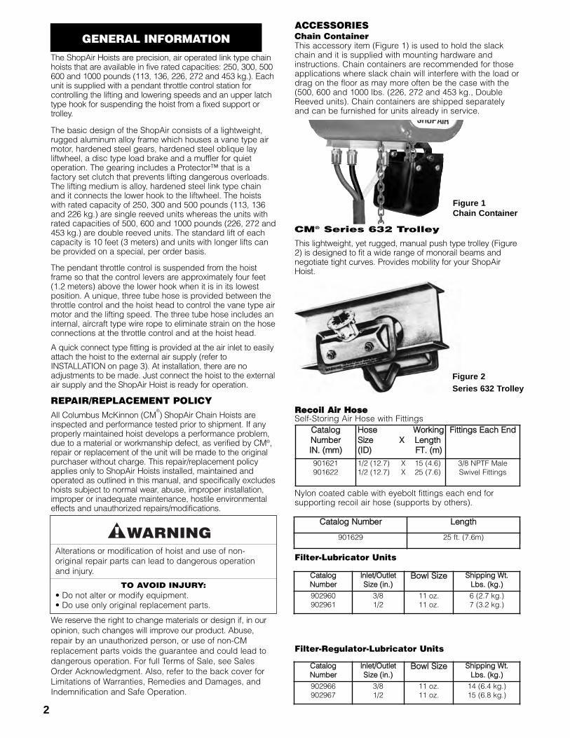
ACCESSORIESChain ContainerThis accessory item (Figure 1) is used to hold the slackchain and it is supplied with mounting hardware andinstructions. Chain containers are recommended for thoseapplications where slack chain will interfere with the load ordrag on the floor as may more often be the case with the(500, 600 and 1000 lbs. (226, 272 and 453 kg., DoubleReeved units). Chain containers are shipped separatelyand can be furnished for units already in service.
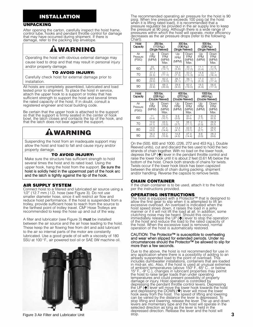
CM® Series 632 TrolleyCMCMies 63
This lightweight, yet rugged, manual push type trolley (Figure2) is designed to fit a wide range of monorail beams andnegotiate tight curves. Provides mobility for your ShopAirHoist.
RReeccooiill AAiirr HHoosseeSelf-Storing Air Hose with Fittings
Nylon coated cable with eyebolt fittings each end forsupporting recoil air hose (supports by others).
Filter-Lubricator Units
Filter-Regulator-Lubricator Units
GENERAL INFORMATION
Figure 1Chain Container
Figure 2Series 632 Trolley
CCaattaallooggNNuummbbeerrIINN.. ((mmmm))
HHoossee WWoorrkkiinnggSSiizzee XX LLeennggtthh((IIDD)) FFTT.. ((mm))
FFiittttiinnggss EEaacchh EEnndd
901621901622
1/2 (12.7) X 15 (4.6)1/2 (12.7) X 25 (7.6)
3/8 NPTF MaleSwivel Fittings
CCaattaalloogg NNuummbbeerr LLeennggtthh
901629 25 ft. (7.6m)
CCaattaalloogg NNuummbbeerr
IInnlleett//OOuuttlleett SSiizzee ((iinn..))
BBoowwll SSiizzee SShhiippppiinngg WWtt..LLbbss.. ((kkgg..))
902960902961
3/81/2
11 oz.11 oz.
6 (2.7 kg.)7 (3.2 kg.)
CCaattaalloogg NNuummbbeerr
IInnlleett//OOuuttlleett SSiizzee ((iinn..))
BBoowwll SSiizzee SShhiippppiinngg WWtt..LLbbss.. ((kkgg..))
902966902967
3/81/2
11 oz.11 oz.
14 (6.4 kg.)15 (6.8 kg.)
3
UNPACKINGAfter opening the carton, carefully inspect the hoist frame,control tube, hooks and pendant throttle control for damagethat may have occurred during shipment. If there isdamage, refer to the packing slip envelope.
All hoists are completely assembled, lubricated and loadtested prior to shipment. To place the hoist in service,attach the upper hook to a support or trolley that hassufficient strength to support the hoist and several timesthe rated capacity of the hoist. If in doubt, consult aregistered engineer and local building code.
Be certain that the upper hook is attached to the supportso that the support is firmly seated in the center of hookbowl, the latch closes and contacts the tip of the hook, andthat the latch does not bear against the support.
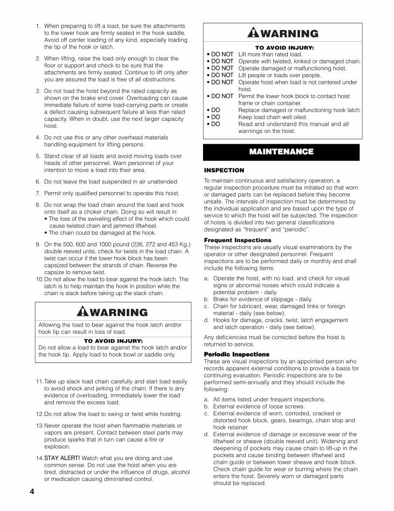
AIR SUPPLY SYSTEMConnect hoist to a filtered and lubricated air source using a1/2” (12.7 mm.) I.D. hose (see Figure 3). Do not usesmaller diameter hose, since it will restrict air flow andreduce hoist performance. If the hoist is suspended from atrolley, provide sufficient hose to reach from the source tothe farthest point of trolley travel. CM® Hose Trolleys arerecommended to keep the hose up and out of the way.
A filter and lubricator (see Figure 3) mmuusstt be installedbetween the air source and the air hose leading to the hoist.These keep the air flowing free from dirt and add lubricantto the air so internal parts of the motor are constantlylubricated. Use a good grade of oil with a viscosity of 180SSU at 100 0 F., air powered tool oil or SAE 0W machine oil.
The recommended operating air pressure for the hoist is 90psig. When line pressure exceeds 100 psig (at the hoistwhen it is lifting rated load), it is recommended that apressure regulator be provided in the air supply line to keepthe pressure at 90 psig. Although there is a wide range ofpressures within which the hoist will operate, motor efficiencydecreases as the air pressure drops (refer to the followingChart).
On the (500, 600 and 1000, (226, 272 and 453 Kg.), DoubleReeved units), cut and discard the ties used to hold the twostrands of chain together. With no load on the lower hook,depress the UP (�) lever in the pendant throttle control andraise the lower hook until it is about 2 feet (0.61 M) below thebottom of the hoist. Check both strands of chains for twists.Twists occur if the lower hook block has been capsizedbetween the strands of chain during packing, shipmentand/or handling. Reverse the capsize to remove twists.
CHAIN CONTAINERIf the chain container is to be used, attach it to the hoistper the instructions provided.
OPERATING INSTRUCTIONSThe hoist is equipped with a Protector™ that is designed toallow the first gear to slip when it is attempted to lift anexcessive overload. An overload is indicated when thehoist speed slows down, it raises the load in a jerkymanner or if it will not lift the load at all. In addition, someclutching noise may be heard. Should this occur,immediately release the UP (�) lever to stop the operationof the hoist and reduce the load to the rated capacity ofthe hoist. When the excessive load is removed, normaloperation of the hoist is automatically restored.
CCAAUUTTIIOONN:: TThhee PPrrootteeccttoorr™™ iiss ssuusscceeppttiibbllee ttoo oovveerrhheeaattiinnggaanndd wweeaarr wwhheenn sslliippppeedd ffoorr eexxtteennddeedd ppeerriiooddss.. UUnnddeerr nnoocciirrccuummssttaanncceess sshhoouulldd tthhee PPrrootteeccttoorr™™ bbee aalllloowweedd ttoo sslliipp ffoorrmmoorree tthhaann aa ffeeww sseeccoonnddss..Due to the above, the hoist is not recommended for use inany application where there is a possibility of adding to analready suspended load to the point of overload. Thisincludes dumbwaiter installations, containers that are loadedin mid-air, etc. Also, if the hoist is used at unusual extremesof ambient temperatures (above 1500 F., 650 C., or below150 F., -90 C.), changes in lubricant properties may permitthe hoist to raise larger loads than under operatingtemperatures and could present possibility of propertydamage or injury. Hoist operation is controlled bydepressing the pendant throttle control levers. Depressingthe UP (�) lever will move the lower hook towards the hoistand depressing the DOWN (�) lever will move the lowerhook away from the hoist. The speed of lifting and loweringcan be varied by the distance the lever is depressed. Tostop lifting and lowering, release the lever. The up and downlevers are momentary type and the hoist will operate in theselected direction as long as the lever is held in thedepressed direction. Release the lever and the hoist willstop.
Operating the hoist with obvious external damage maycause load to drop and that may result in personal injuryand/or property damage.
TO AVOID INJURY:Carefully check hoist for external damage prior toinstallation.
Suspending the hoist from an inadequate support mayallow the hoist and load to fall and cause injury and/orproperty damage.
TO AVOID INJURY:Make sure the structure has sufficient strength to holdseveral times the hoist and its rated load. Using theupper hook, hang the hoist from the support. BBee ssuurree tthheehhooiisstt iiss ssoolliiddllyy hheelldd iinn tthhee uuppppeerrmmoosstt ppaarrtt ooff tthhee hhooookk aarrccaanndd tthhee llaattcchh iiss ttiigghhttllyy aaggaaiinnsstt tthhee ttiipp ooff tthhee hhooookk..
INSTALLATION
Figure 3 Air Filter and Lubricator Unit
HHooiissttCCaappaacciittyy
225500 llbbss..((111133 KKgg..))
((SSiinnggllee RReeeevveedd))
330000 llbbss..((113366 KKgg..))
((SSiinnggllee RReeeevveedd))
550000 llbbss..((222266 KKgg..))
((SSiinnggllee RReeeevveedd))Air
Pressure(PSIG)
UpFPM(MPM)
DownFPM(MPM)Max.
UpFPM(MPM)
DownFPM(MPM)Max.
UpFPM(MPM)
DownFPM(MPM)Max.
60 22(6.7)
46.2(14.1)
19.1(5.8)
40.1(12.2)
11.1(3.4)
41.6(12.7)
70 27.2(8.3)
57.1(17.4)
23.9(7.3)
50.2(15.3)
14.8(4.5)
53.7(16.4)
80 29.6(9.0)
62.2(19.0)
26.7(8.1)
56.1(17.1)
17.3(5.3)
57.1(17.4)
90 32.5(9.9)
68.3(20.8)
29.6(9.0)
62.2(19.0)
19.5(5.9)
56.6(17.3)
HHooiissttCCaappaacciittyy
550000 llbbss..((222266 KKgg..))
((DDoouubbllee RReeeevveedd))
660000 llbbss..((227722 KKgg..))
((DDoouubbllee RReeeevveedd))
11000000 llbbss..((445533 KKgg..))
((DDoouubbllee RReeeevveedd)) Air
Pressure(PSIG)
UpFPM(MPM)
DownFPM(MPM)Max.
UpFPM(MPM)
DownFPM(MPM)Max.
UpFPM(MPM)
DownFPM(MPM)Max.
60 11(3.4)
35.2(10.7)
9.6(3.0)
30.7(9.4)
5.6(1.7)
20.8(6.3)
70 13.6(4.1)
43.5(13.3)
12(3.7)
38.4(11.7)
7.4(2.3)
26.9(8.2)
80 14.8(4.5)
47.4(14.4)
13.4(4.1)
42.9(13.1)
8.7(2.7)
28.6(8.7)
90 16.3(5.0)
52.2(15.9)
14.8(4.5)
47.4(14.4)
9.8(3.0)
28.3(8.6)
4
Hoist PowerCord
Green-Yellow
*Manual Disconnect Switch
Black
White
Ground
*Slow Blow Fusesor Inverse Time Circuit Breakers
*Thermal OverloadRelay
*Receptacle Rated for 15 Amps Minimum. (220-1-50 Units Do Not Include Power CordPlug) Wire Blue and Brown Wires to Fuses or Circuit Breakers and Green-Yellow Wire toGround.
BrownBlue
Figure 4A
1. When preparing to lift a load, be sure the attachmentsto the lower hook are firmly seated in the hook saddle. Avoid off center loading of any kind, especially loading the tip of the hook or latch.
2. When lifting, raise the load only enough to clear thefloor or support and check to be sure that the attachments are firmly seated. Continue to lift only after you are assured the load is free of all obstructions.
3. Do not load the hoist beyond the rated capacity as shown on the brake end cover. Overloading can cause immediate failure of some load-carrying parts or create a defect causing subsequent failure at less than rated capacity. When in doubt, use the next larger capacity hoist.
4. Do not use this or any other overhead materials handling equipment for lifting persons.
5. Stand clear of all loads and avoid moving loads overheads of other personnel. Warn personnel of your intention to move a load into their area.
6. Do not leave the load suspended in air unattended.
7. Permit only qualified personnel to operate this hoist.
8. Do not wrap the load chain around the load and hookonto itself as a choker chain. Doing so will result in:• The loss of the swiveling effect of the hook which couldcause twisted chain and jammed liftwheel.
• The chain could be damaged at the hook.
9. On the 500, 600 and 1000 pound (226, 272 and 453 Kg.)double reeved units, check for twists in the load chain. A twist can occur if the lower hook block has been capsized between the strands of chain. Reverse the capsize to remove twist.
10.Do not allow the load to bear against the hook latch. The latch is to help maintain the hook in position while the chain is slack before taking up the slack chain.
11.Take up slack load chain carefully and start load easily to avoid shock and jerking of the chain. If there is any evidence of overloading, immediately lower the load and remove the excess load.
12.Do not allow the load to swing or twist while hoisting.
13.Never operate the hoist when flammable materials orvapors are present. Contact between steel parts may produce sparks that in turn can cause a fire orexplosion.
14.SSTTAAYY AALLEERRTT!! Watch what you are doing and use common sense. Do not use the hoist when you are tired, distracted or under the influence of drugs, alcoholor medication causing diminished control.
INSPECTION
To maintain continuous and satisfactory operation, aregular inspection procedure must be initiated so that wornor damaged parts can be replaced before they becomeunsafe. The intervals of inspection must be determined bythe individual application and are based upon the type ofservice to which the hoist will be subjected. The inspectionof hoists is divided into two general classificationsdesignated as “frequent” and “periodic”.
Frequent InspectionsThese inspections are usually visual examinations by theoperator or other designated personnel. Frequentinspections are to be performed daily or monthly and shallinclude the following items:
a. Operate the hoist, with no load, and check for visual signs or abnormal noises which could indicate a potential problem - daily.
b. Brake for evidence of slippage - daily.c. Chain for lubricant, wear, damaged links or foreign
material - daily (see below).d. Hooks for damage, cracks, twist, latch engagement
and latch operation - daily (see below).
Any deficiencies must be corrected before the hoist isreturned to service.
PPeerriiooddiicc IInnssppeeccttiioonnssThese are visual inspections by an appointed person whorecords apparent external conditions to provide a basis forcontinuing evaluation. Periodic inspections are to beperformed semi-annually and they should include thefollowing:
a. All items listed under frequent inspections.b. External evidence of loose screws.c. External evidence of worn, corroded, cracked or
distorted hook block, gears, bearings, chain stop and hook retainer.
d. External evidence of damage or excessive wear of theliftwheel or sheave (double reeved unit). Widening and deepening of pockets may cause chain to lift-up in the pockets and cause binding between liftwheel and chain guide or between lower sheave and hook block. Check chain guide for wear or burring where the chain enters the hoist. Severely worn or damaged parts should be replaced.
Allowing the load to bear against the hook latch and/orhook tip can result in loss of load.
TO AVOID INJURY:Do not allow a load to bear against the hook latch and/orthe hook tip. Apply load to hook bowl or saddle only.
TO AVOID INJURY:•• DDOO NNOOTT Lift more than rated load.• DDOO NNOOTT Operate with twisted, kinked or damaged chain. • DDOO NNOOTT Operate damaged or malfunctioning hoist.• DDOO NNOOTT Lift people or loads over people.• DDOO NNOOTT Operate hoist when load is not centered under
hoist.• DDOO NNOOTT Permit the lower hook block to contact hoist
frame or chain container.• DDOO Replace damaged or malfunctioning hook latch.• DDOO Keep load chain well oiled.• DDOO Read and understand this manual and all
warnings on the hoist.
MMAAIINNTTEENNAANNCCEE
LOAD CHAINChain should feed smoothly into and away from the hoistor hook block (500, 600 and 1000#, 226, 272 and 453 Kg.units). If chain binds, jumps or is noisy, first clean andlubricate it (see below). If trouble persists, inspect chainand mating parts for wear, distortion or other damage.
Chain InspectionFirst clean chain with a non-caustic/non-acid type solventand make a link by link inspection for nicks, gouges,twisted links, weld spatter, corrosion pits, sitriations(minute parallel lines), cracks in weld areas, wear andstretching. Chain with any one of these defects must bereplaced.
Slack the portion of the chain that normally passes overthe liftwheel. Examine the interlink area for the point ofmaximum wear (polishing, see figure 5). Measure andrecord the stock diameter at this point of the link. Thenmeasure stock diameter in the same area on a link thatdoes not pass over the liftwheel (use the link adjacent tothe loose end link for this purpose). Compare these twomeasurements. If the stock diameter of the worn link is0.010 inches (0.254 mm.), or more, less than the stockdiameter of the unworn link, the chain must be replaced.
On the 500, 600 and 1000# (226, 272 and 453 Kg.) units,repeat this examination of the chain that passes through thehook block.
Also check chain for stretch using a vernier caliper asshown in figure 6. Select an unused, unstretched sectionof chain (usually at the loose end) and measure andrecord the length over 11 chain links (pitches). Measureand record the same length on a worn section of chain.Obtain the amount of stretch and wear by subtracting themeasurement of the unworn section from the measurementof the worn section. If the result (amount of stretch andwear) is greater than 0.145 inch (3.7 mm.), the chain mustbe replaced.
Use only a “Knife-edge” caliper to eliminate possibility offalse reading by not measuring full pitch length.
5
e. External evidence of excessive wear of brake parts -see page 7.
f. Check the control station levers to make sure theyoperate freely and spring back when released.
g. Check air supply hose and control hose for kinks, cuts,leaks and damage.
h. Check the chain pin or dead end pin and chain stopfor wear and cracks.
i. Check for lubricant leaks at gasket between mainframe and gear housing. Tighten gear housing screwsto stop leak. If leak persists, replace gasket.
j. Inspect splines on first pinion shaft and motor couplingfor signs of wear or deterioration. Replace splinedparts if worn or damaged.
k. Check for air leaks at brake end cap. Replace piston seals to stop leaks.
l. Check for air leaks at the joints of the motor. Tighten screws to stop leaks. If leaks persist, disassemble motor, see page 8, and replace seals.
m. Check for air leaks at joint between the supply block and valve body. Tighten screws or replace gasket to stop leaks.
n. Check for air leaks at o-rings on top and under valve body. Tighten valve bolt or replace o-ring to stop leaks.
NNOOTTEE:: TToo ppeerrffoorrmm ssoommee ooff tthhee ppeerriiooddiicc iinnssppeeccttiioonnss,, iitt iissnneecceessssaarryy ttoo ppaarrttiiaallllyy ddiissaasssseemmbbllee tthhee hhooiisstt.. RReeffeerr ttooDDiissaasssseemmbbllyy--AAsssseemmbbllyy ssttaarrttiinngg oonn ppaaggee 88..
Any deficiencies noted must be corrected before the hoistis returned to service. Also, the external conditions mayshow the need for more detailed inspection which, in turn,may require the use of nondestructive-type testing.
Any parts that are deemed unserviceable are to bereplaced with new parts before the unit is returned toservice. It is very important that the unserviceable partsbe destroyed to prevent possible future use as a repairitem and properly disposed of.
Hook InspectionHook damage from chemicals, deformations or cracks orthat have more than a 100 twist from the plane of theunbent hook or excessive opening must be replaced.
Any hook that is twisted or has excessive throat openingindicates abuse or overloading of the unit. Other load-sustaining components of the hoist should be inspectedfor damage.
On latch type hooks, check to make sure that the latch isnot damaged or bent and that it operates properly withsufficient spring pressure to keep the latch tightly againstthe tip of the hook and allow the latch to spring back tothe tip when released. See below to determine when thehook must be replaced.
FFiigguurree 44.. HHooookk IInnssppeeccttiioonn
FFiigguurree 55.. CChhaaiinn WWeeaarr AArreeaass
FFiigguurree 66.. CChhaaiinn IInnssppeeccttiioonn
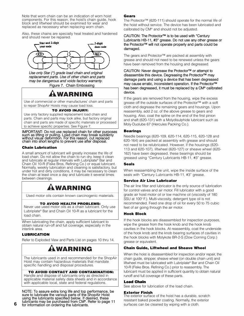
Note that worn chain can be an indication of worn hoistcomponents. For this reason, the hoist’s chain guide, hookblock and liftwheel should be examined for wear andreplaced as necessary when replacing worn chain.
Also, these chains are specially heat treated and hardenedand should never be repaired.
IIMMPPOORRTTAANNTT:: DDoo nnoott uussee rreeppllaacceedd cchhaaiinn ffoorr ootthheerr ppuurrppoosseessssuucchh aass lliiffttiinngg oorr ppuulllliinngg.. LLooaadd cchhaaiinn mmaayy bbrreeaakk ssuuddddeennllyywwiitthhoouutt vviissuuaall ddeeffoorrmmttiioonn.. FFoorr tthhiiss rreeaassoonn,, ccuutt rreeppllaacceeddcchhaaiinn iinnttoo sshhoorrtt lleennggtthhss ttoo pprreevveenntt uussee aafftteerr ddiissppoossaall..
Chain LubricationA small amount of lubricant will greatly increase the life ofload chain. Do not allow the chain to run dry. keep it cleanand lubricate at regular intervals with Lubriplate® Bar andChain Oil 10-R (Fiske Bros, Refining Co.) or equal lubricant.Normally, weekly lubrication and cleaning is satisfactory, butunder hot and dirty conditions, it may be necessary to cleanthe chain at least once a day and lubricate it several timesbetween cleanings.
When lubricating the chain, apply sufficient lubricant toobtain natural run-off and full coverage, especially in theinterlink area.
LUBRICATIONRefer to Exploded View and Parts List on pages 10 thru 14.
NNOOTTEE:: TToo aassssuurree eexxttrraa lloonngg lliiffee aanndd ttoopp ppeerrffoorrmmaannccee,, bbeessuurree ttoo lluubbrriiccaattee tthhee vvaarriioouuss ppaarrttss ooff tthhee SShhooppAAiirr HHooiissttuussiinngg tthhee lluubbrriiccaannttss ssppeecciiffiieedd bbeellooww.. IIff ddeessiirreedd,, tthheesseelluubbrriiccaannttss mmaayy bbee ppuurrcchhaasseedd ffrroomm CCMM®®.. RReeffeerr ttoo ppaaggee 1111ffoorr iinnffoorrmmaattiioonn oonn oorrddeerriinngg tthhee lluubbrriiccaannttss..6
Use of commercial or other manufactures’ chain and partsto repair ShopAir Hoists may cause load loss.
TO AVOID INJURY:Use only factory supplied replacement load chain andparts. Chain and parts may look alike, but factory originalchain and parts are made of specific materials or processedto achieve specific properties. See Figure 7.
Used motor oils contain known carcinogenic materials.
TO AVOID HEALTH PROBLEMS:Never use used motor oils as a chain lubricant. Only useLubriplate® Bar and Chain Oil 10-R as a lubricant for theload chain.
The lubricants used in and recommended for the ShopAirHoist may contain hazardous materials that mandatespecific handling and disposal procedures.
TO AVOID CONTACT AND CONTAMINATION:Handle and dispose of lubricants only as directed inapplicable material safety data sheets and in accordancewith applicable local, state and federal regulations.
GearsThe Protector™ (620-111) should operate for the normal life ofthe hoist without service. The device has been lubricated andcalibrated by CM® and should not be adjusted.
CCAAUUTTIIOONN:: TThhee PPrrootteeccttoorr™™ iiss ttoo bbee uusseedd wwiitthh ““CCeennttuurryyLLuubbrriiccaannttss HHBB--1111,, ##33”” ggrreeaassee.. DDoo nnoott uussee aannyy ootthheerr ggrreeaassee oorrtthhee PPrrootteeccttoorr™™ wwiillll nnoott ooppeerraattee pprrooppeerrllyy aanndd ppaarrttss ccoouulldd bbeeddaammaaggeedd..
The gears and Protector™ are packed at assembly withgrease and should not need to be renewed unless the gearshave been removed from the housing and degreased.
CCAAUUTTIIOONN:: NNeevveerr ddeeggrreeaassee tthhee PPrrootteeccttoorr™™ oorr aatttteemmpptt ttooddiissaasssseemmbbllee tthhiiss ddeevviiccee.. DDeeggrreeaassiinngg tthhee PPrrootteeccttoorr™™ mmaayyddaammaaggee ppaarrttss aanndd uussiinngg aa ddeevviiccee tthhaatt hhaass bbeeeenn ddeeggrreeaasseeddmmaayy ccaauussee eerrrraattiicc,, iinnccoonnssiisstteenntt ooppeerraattiioonn.. IIff tthhee PPrrootteeccttoorr™™hhaass bbeeeenn ddeeggrreeaasseedd,, iitt mmuusstt bbee rreeppllaacceedd bbyy aa CCMM®® ccaalliibbrraatteeddddeevviiccee..
If the gears are removed from the housing, wipe the excessgrease off the outside surfaces of the Protector™ with a softcloth and degrease the remaining gears and housings. Uponreassembly, add 2 oz. of the above grease to gears andhousing. Also, coat the spline on the end of the first pinionand shaft (620-131) with a Molydisulphide lubricant such asMoly-Duolube 67 (Hercules Packing Co.).
BearingsNeedle bearings (620-109, 620-114, 620-115, 620-128 and620-164) are packed at assembly with grease and shouldnot need to be relubricated. However, if the housings (620-113 and 620-107), liftwheel (620-127) or sheave wheel (620-162) have been degreased, these bearings should begreased using “Century Lubricants HB-11, #3” grease.
Seals
When reassembling the unit, wipe the inside surface of theseals with “Century Lubricants HB-11, #3” grease.
Service Air Line LubricatorThe air line filter and lubricator is the only source of lubricationfor control valves and air motor. Fill lubricator with a goodgrade air hoist motor oil or low machine oil (viscosity of 180SSU at 1000 F.). Multi-viscosity, detergent type oil is notrecommended. Feed one drop of oil for every 50 to 75 cubicfeet of air going through the air motor.
Hook Block
If the hook blocks are disassembled for inspection purposes,wipe the grease from the hook knob and the hook knobcavities in the hook blocks. At reassembly, coat the undersideof the hook knob and the knob bearing surfaces of cavities inthe hook blocks with Molykote BR-2-S (Dow Corning Corp.)grease or equivalent.
Chain Guide, Liftwheel and Sheave Wheel
When the hoist is disassembled for inspection and/or repair, thechain guide, stripper, sheave wheel (on double chain unit) andliftwheel must be lubricated with Lubriplate® Bar and Chain Oil10-R (Fiske Bros. Refining Co.) prior to reassembly. Thelubricant must be applied in sufficient quantity to obtain naturalrunoff and full coverage of these parts.
LLooaadd CChhaaiinnSee above for lubrication of the load chain.
Exterior FinishThe exterior surface of the hoist has a durable, scratchresistant baked powder coating. Normally, the exteriorsurfaces can be cleaned by wiping with a cloth.
FFiigguurree 77.. CChhaaiinn EEmmbboossssiinngg
UUssee oonnllyy SSttaarr ((**)) ggrraaddee llooaadd cchhaaiinn aanndd oorriiggiinnaallrreeppllaacceemmeenntt ppaarrttss.. UUssee ooff ootthheerr cchhaaiinn aanndd ppaarrttssmmaayy bbee ddaannggeerroouuss aanndd vvooiiddss ffaaccttoorryy wwaarrrraannttyy..
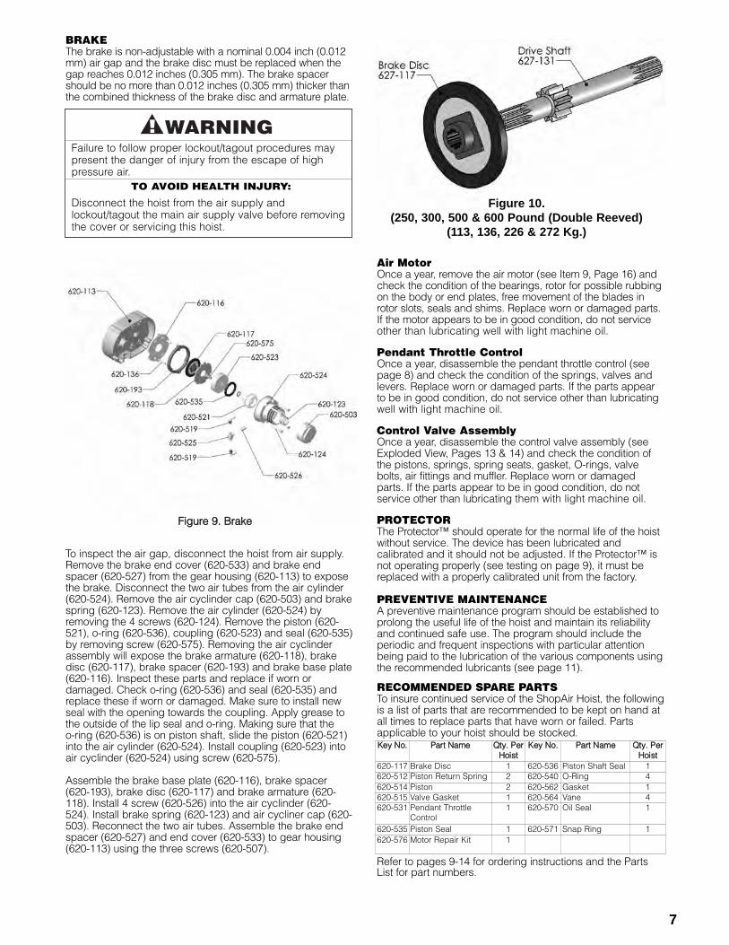
BRAKEThe brake is non-adjustable with a nominal 0.004 inch (0.012mm) air gap and the brake disc must be replaced when thegap reaches 0.012 inches (0.305 mm). The brake spacershould be no more than 0.012 inches (0.305 mm) thicker thanthe combined thickness of the brake disc and armature plate.
To inspect the air gap, disconnect the hoist from air supply.Remove the brake end cover (620-533) and brake endspacer (620-527) from the gear housing (620-113) to exposethe brake. Disconnect the two air tubes from the air cylinder(620-524). Remove the air cyclinder cap (620-503) and brakespring (620-123). Remove the air cylinder (620-524) byremoving the 4 screws (620-124). Remove the piston (620-521), o-ring (620-536), coupling (620-523) and seal (620-535)by removing screw (620-575). Removing the air cyclinderassembly will expose the brake armature (620-118), brakedisc (620-117), brake spacer (620-193) and brake base plate(620-116). Inspect these parts and replace if worn ordamaged. Check o-ring (620-536) and seal (620-535) andreplace these if worn or damaged. Make sure to install newseal with the opening towards the coupling. Apply grease tothe outside of the lip seal and o-ring. Making sure that the o-ring (620-536) is on piston shaft, slide the piston (620-521)into the air cylinder (620-524). Install coupling (620-523) intoair cyclinder (620-524) using screw (620-575).
Assemble the brake base plate (620-116), brake spacer(620-193), brake disc (620-117) and brake armature (620-118). Install 4 screw (620-526) into the air cyclinder (620-524). Install brake spring (620-123) and air cycliner cap (620-503). Reconnect the two air tubes. Assemble the brake endspacer (620-527) and end cover (620-533) to gear housing(620-113) using the three screws (620-507).
Failure to follow proper lockout/tagout procedures maypresent the danger of injury from the escape of highpressure air.
TO AVOID HEALTH INJURY:
Disconnect the hoist from the air supply andlockout/tagout the main air supply valve before removingthe cover or servicing this hoist.
Air MotorOnce a year, remove the air motor (see Item 9, Page 16) andcheck the condition of the bearings, rotor for possible rubbingon the body or end plates, free movement of the blades inrotor slots, seals and shims. Replace worn or damaged parts.If the motor appears to be in good condition, do not serviceother than lubricating well with light machine oil.
Pendant Throttle ControlOnce a year, disassemble the pendant throttle control (seepage 8) and check the condition of the springs, valves andlevers. Replace worn or damaged parts. If the parts appearto be in good condition, do not service other than lubricatingwell with light machine oil.
Control Valve AssemblyOnce a year, disassemble the control valve assembly (seeExploded View, Pages 13 & 14) and check the condition ofthe pistons, springs, spring seats, gasket, O-rings, valvebolts, air fittings and muffler. Replace worn or damagedparts. If the parts appear to be in good condition, do notservice other than lubricating them with light machine oil.
PROTECTORThe Protector™ should operate for the normal life of the hoistwithout service. The device has been lubricated andcalibrated and it should not be adjusted. If the Protector™ isnot operating properly (see testing on page 9), it must bereplaced with a properly calibrated unit from the factory.
PREVENTIVE MAINTENANCEA preventive maintenance program should be established toprolong the useful life of the hoist and maintain its reliabilityand continued safe use. The program should include theperiodic and frequent inspections with particular attentionbeing paid to the lubrication of the various components usingthe recommended lubricants (see page 11).
RECOMMENDED SPARE PARTSTo insure continued service of the ShopAir Hoist, the followingis a list of parts that are recommended to be kept on hand atall times to replace parts that have worn or failed. Partsapplicable to your hoist should be stocked.
Refer to pages 9-14 for ordering instructions and the PartsList for part numbers.
7
FFiigguurree 99.. BBrraakkee
KKeeyy NNoo.. PPaarrtt NNaammee QQttyy.. PPeerrHHooiisstt
KKeeyy NNoo.. PPaarrtt NNaammee QQttyy.. PPeerrHHooiisstt
620-117 Brake Disc 1 620-536 Piston Shaft Seal 1620-512 Piston Return Spring 2 620-540 O-Ring 4620-514 Piston 2 620-562 Gasket 1620-515 Valve Gasket 1 620-564 Vane 4620-531 Pendant Throttle
Control1 620-570 Oil Seal 1
620-535 Piston Seal 1 620-571 Snap Ring 1620-576 Motor Repair Kit 1
Figure 10.(250, 300, 500 & 600 Pound (Double Reeved)
(113, 136, 226 & 272 Kg.)
8
When disassembling and assembling the ShopAir Hoist,refer to the exploded view and the parts list on pages 10thru 14. These show the proper relationship of the parts,the names of the parts and the required quantities of theparts. In addition, please observe the following:
1. Needle bearings are pressed into the gear housing(620-113), main frame (620-107), liftwheel (620-127)and lower sheave wheel (620-162). Unless they are tobe replaced, do not attempt to remove these bearings.
2. A liftwheel seal (620-108) is pressed into the main frame(620-107) and a seal (620-130) is pressed into the endof the liftwheel shaft (620-148). Be careful that theseseals are not cut or damaged during disassembly andreassembly.
3. Refer to page 7 for disassembly, inspection andreassembly of the brake.
4. Do not attempt to disassemble the Protector™ - refer topage 7.
5. Refer to page 6 for lubrication instructions.6. See next section for load chain removal and installation.7. Tighten the various screws as follows:
KEY-NO. PART NAME SEATING TORQUELB. IN. NM
620-126 Pin Retainer Plate Screw 25 2.8620-154 Motor Cover Screw 25 2.8620-134 Gear Housing Screw 25 2.8620-133 Brake End Cover Screw 25 2.8620-168 Dead End Plate Screw 125 14.1620-140 Hook Retainer Screw 10 1.1620-157 Hook Block Screw
500, 600 and 1000 lbs. (226, 272 and 453 Kg.) (Double Reeved) units 125 14.1250, 300 and 500 lbs.(113, 136 and 226 Kg.)(Single Reeved) units 50 5.6
620-510 Motor Screws 25 2.8620-517 Valve Block Screws 25 2.8620-518 Supply Bolt 50 5.68. To remove the air motor (620-538), remove the motor
end cover (620-502) and motor end spacer (620-528).Loose the valve bolts (620-518) enough to remove thevalve block assembly from the bottom of the motor.Remove the two screws used to attach the motor to themain frame (620-107) and carefully slide the motor shaftout of the coupling (620-508). If necessary, refer topage 9 for instructions for disassembling the motor.
9. To install the air motor (620-538), slide the coupling (650-508) onto the end of the motor shaft. Align splines on thefirst pinion and shaft (620-131) and coupling and thenslide the motor into position. Secure the motor to the mainframe (620-107) using two screws. Attach the valveassembly to the bottom of the motor using the two valvebolts (620-518), making sure the O-rings are on the valvebolts. Assemble the motor end spacer (620-528) andmotor end cover (620-502) to the main frame using threescrews.
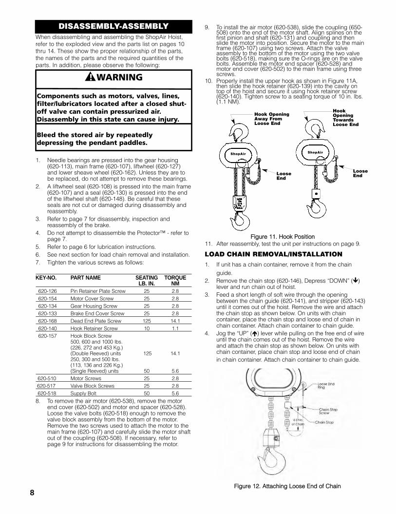
10. Properly install the upper hook as shown in Figure 11A,then slide the hook retainer (620-139) into the cavity ontop of the hoist and secure it using hook retainer screw(620-140). Tighten screw to a seating torque of 10 in. lbs.(1.1 NM).
11. After reassembly, test the unit per instructions on page 9.
LOAD CHAIN REMOVAL/INSTALLATION1. If unit has a chain container, remove it from the chain
guide.2. Remove the chain stop (620-146), Depress “DOWN” (�)
lever and run chain out of hoist.3. Feed a short length of soft wire through the opening
between the chain guide (620-141), and stripper (620-143)until it comes out of the hoist. Remove the wire and attachthe chain stop as shown below. On units with chaincontainer, place the chain stop and loose end of chain inchain container. Attach chain container to chain guide.
4. Jog the “UP” (�) lever while pulling on the free end of wireuntil the chain comes out of the hoist. Remove the wireand attach the chain stop as shown below. On units withchain container, place chain stop and loose end of chain in chain container. Attach chain container to chain guide.
DISASSEMBLY-ASSEMBLY
FFiigguurree 1122.. AAttttaacchhiinngg LLoooossee EEnndd ooff CChhaaiinn
ShopAir ShopAir
Hook OpeningAway FromLoose End
HookOpeningTowardsLoose End
LooseEndLoose
End
FFiigguurree 1111.. HHooookk PPoossiittiioonn
� ! WARNING
Components such as motors, valves, lines,filter/lubricators located after a closed shut-off valve can contain pressurized air.Disassembly in this state can cause injury.
Bleed the stored air by repeatedlydepressing the pendant paddles.
CUTTING CHAIN
Hoistaloy® load chain is hardened and it is difficult to cut.The following methods are recommended when cutting alength of new chain from stock or cutting off worn chain.Always wear eye protection when cutting chain.
1. Use a grinder and nickthe link on both sides(see right), then securethe link in a vise andbreak off with ahammer.
2. Use a 7”(177 mm) minimum diameter by 1/8" (3.1 mm)thick abrasive wheel (or type recommended by wheelsupplier) that will clear adjacent links.
3. Use a bolt cutter (seeright) with special cutterjaws for cutting hardenedchain. Jaws should be 1inch (25.4 mm) long.
Cutting chain can produce flying particles.TO AVOID HEALTH PROBLEMS:
• Wear eye protection.• Place a shield over chain to prevent flying objects.
TESTINGBefore using, all altered, repaired or used hoists that havenot been operated for the previous 12 months must betested by the user for proper operation. First, test the unitwithout a load and then with a light load of 50 pounds (23kg) times the number of load supporting parts of loadchain to be sure that the hoist operates properly and thatthe brake holds the load when control is released. Next testwith a load of *125% of rated capacity. In addition hoists inwhich load sustaining parts have been replaced should betested with *125% of rated capacity by or under thedirection of an appointed person and a written reportprepared for record purposes. After this test, check theProtector™ functions. If the Protector™ permits lifting aload in excess of 200% of rated load, it should bereplaced.
*If the Protector™ prevents lifting of a load of 125% ofrated capacity, reduce load to rated capacity.
NNOOTTEE:: FFoorr aaddddiittiioonnaall iinnffoorrmmaattiioonn oonn iinnssppeeccttiioonn aanndd tteessttiinngg,,rreeffeerr ttoo AASSMMEE BB3300..1166 ““OOvveerrhheeaadd HHooiissttss”” oobbttaaiinnaabbllee ffrroommAASSMMEE OOrrddeerr DDeeppaarrttmmeenntt,, 2222 LLaaww DDrriivvee,, BBooxx 22330000,,FFaaiirrffiieelldd,, NNJJ 0077000077--22330000,, UU..SS..AA..
ORDERING INSTRUCTIONSThe following information must accompany allcorrespondence and orders for replacement parts:
1. Hoist rated load from identification plate.
2. Serial number of the hoist from identification plate.
3. Length of lift.
4. Key number of part from parts list.
5. Number of parts required.
6. Part name from parts list.
7. Part number from the parts list.
NOTE: When ordering replacement parts, it is recom-mended that consideration be given to the need foralso ordering such items as gaskets, fasteners, seals,etc. These items may be damaged or lost duringdisassembly or just unfit for future use because ofdeterioration from age or service.
Using “commercial” or other manufacturer’s parts to repair theShopAir Hoist may cause load loss.
TO AVOID INJURY:Use only factory supplied replacement parts. Parts may look alikebut factory original parts are made of specific materials orprocessed to achieve specific properties.
9
5. On the 250, 300 and 500# (Single Reeved) (113, 136and 226 kg.) units, remove the hook block from the oldchain and attach it to the new chain by reusing thechain pin (620-158).On the 500, 600 and 1000# (226, 272 and 453 kg.)units:• Remove dead end plate (620-160) from hoist.• Remove dead end pin (620-161) from the last link
of chain and pull chain out of dead end plate.
• Pull old chain out of hook block and disassemble the hook block.
• Make sure the new chain is not twisted and wrap the chain around the sheave wheel (620-162) with welds down and towards the sheave wheel.
• Reassemble hook block and pull the new chain through the hook block.
• Slide the dead end plate over the last link and secure it using the dead end pin.
• Making sure the chain is not twisted between the hook block and hoist, attach the dead end plate to the stripper (620-143).
• Retrace the new chain and check for twists. If chain is twisted, start over.
IIMMPPOORRTTAANNTT:: DDoo nnoott uussee ““oolldd”” cchhaaiinn ffoorr ootthheerr ppuurrppoosseess ssuucchhaass lliiffttiinngg oorr ppuulllliinngg.. LLooaadd cchhaaiinn mmaayy bbrreeaakk ssuuddddeennllyy wwiitthhoouuttvviissuuaall ddeeffoorrmmaattiioonn.. FFoorr tthhiiss rreeaassoonn,, ccuutt tthhee ““oolldd”” cchhaaiinn iinnttoosshhoorrtt lleennggtthhss ttoo pprreevveenntt uussee aafftteerr ddiissppoossaall..
1110
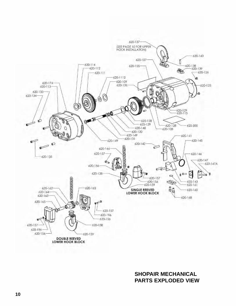
SHOPAIR MECHANICALPARTS EXPLODED VIEW
KKeeyy NNoo.. DDeessccrriippttiioonn QQttyy.. PPaarrtt NNoo..620-107 Main Frame 1 20352620-108 Liftwheel Seal 1 20705620-109 Protector Bearing, Main Frame Side 1 88636
620-111 Protector Assembly500# (Single Reeved) & 1000# Units 1
2064520665
620-112 Thrust Washer, Second Pinion 2 88640620-113 Gear Housing 1 20350620-114 Protector Bearing, Gear Housing 1 88636620-115 First Pinion Bearing 1 88635620-125 Pin Plate 1 20700620-126 Pin Plate Screw 2 20743
620-127Liftwheel and Gear Assembly500# (Single Reeved) & 1000# Units 1
2066420666
620-128 Liftwheel Bearing 2 88637620-129 Thrust Washer, Liftwheel 2 88638620-130 Liftwheel Shaft Seal 1 20704
620-131First Pinion and Shaft
10 Tooth12 Tooth
1 ContactFactory
620-133 Spacer 2 20964620-134 Gear Housing Screw 2 20384620-135 Gear Housing Screw (short) 2 920718620-136 Dowel Pin 4 920720620-137 Upper Hook 1 20650620-138 Hook Latch Kit 2 595522620-139 Hook Retainer 1 20712620-140 Hook Retainer Screw 1 920725620-141 Chain Guide 1 20304620-142 Chain Guide Pin 4 20729620-143 Chain Stripper 1 20305620-144 Load Chain (Specify Length Req’d.) - 85988620-145 Loose End Ring 1 20744620-146 Chain Stop 2 20428620-147 Chain Stop Screw 2 25848620-147A Chain Stop Screw Nut 2 982472620-148 Liftwheel Shaft 1 20313620-149 Thrust Washer, First Pinion 2 88639620-155 Caution Label 1 20758
620-156Hook Block
2 20995500#, 600# and 1000# 2 20739
620-157Hook Block Screw
2 920730500#, 600# and 1000# 2 920724
620-159 Hook (Includes 620-138) 1 23030
SHOPAIR PARTS LIST
KKeeyy NNoo.. DDeessccrriippttiioonn QQttyy.. PPaarrtt NNoo..
620-160Dead End Plate500#, 600# and 1000# 1 20714
620-161Dead End Pin500#, 600# and 1000# 1 920720
620-162Sheave Wheel (Includes 620-164)500#, 600# and 1000# 1 20652
620-163Sheave Wheel Shaft500#, 600# and 1000# 1 20318
620-164Sheave Wheel Bearing500#, 600# and 1000# 1 88641
620-165Sheave Wheel Thrust Washer500#, 600# and 1000# 2 88639
620-168Dead End Plate Screw500#, 600# and 1000# 2 73715
620-174 Gasket 1 20755620-196 Hook Block Lockwasher 2 940802
Part Number for PackagedLubricants
Used in the ShopAir (Refer to Page 6 for Lubrication Instructions)LubricantUsage
TypeLubricant
Part Numbers andPackaged Quantityof Lubricants
Hoist Gears GreaseCentury
Lubricants HB-11,#3
28605 for 1/2 lb. Can28615 for 1 lb. Can28617 for 4 lb. Can.
Spline one end ofFirst Pinion and Shaft
Oil-Graohite MixtureHercules Packing Co.
Moly-Duolube40628 for 1 Pint Can
Load ChainOil
Friske Bros.Lubriplate® Bar andChain Oil #10R
28608 for 1 Pint Can28619 for 1 Gal. Can
Lower Hook Knob GreaseDow Corning
Molykote BR-2-S28606 for 1/2 lb. Can28618 for 1 lb. Can
When ordering lubricants, specify the type of lubricant, partnumber and packaged quantity required.
11
SHOPAIR PARTS LIST
12
KKeeyy NNoo.. DDeessccrriippttiioonn QQttyy.. PPaarrtt NNoo..620-103 Rotor Bearing, Inboard 1 88486620-116 Brake Base Plate 1 20419
620-117 Brake Disc 1 ContactFactory
620-118 Armature Plate 1 20420620-123 Brake Spring 1 20887620-124 Brake Screw 4 920740
620-169
Capacity Plate250# 1 20762300# 1 20737500# 1 20763600# 1 207381000# 1 20884
620-183 Hole Plug 1 20780620-184 Hole Plug 1 20781620-193 Brake Spacer 1 20723620-501 ShopAir Label 1 20943620-502 Motor Cover, Orange 1 20415C620-503 Cylinder Cap 1 20425620-504 Motor Cover Screw (1.75” Lg.) 1 20947620-505 Motor Cover Screw (3.50” Lg.) 1 20957620-506 Motor Cover Screw (5.75” Lg.) 1 20945620-507 Brake Cover Screw 3 20946620-508 Motor Coupling 1 20391620-509 Air Tubing (Specify Length Req’d.) 1 20948620-510 Air Motor Screw 2 20958620-511 Valve Body 1 20392620-512 Piston Return Spring 2 20949620-513 Spring Seat 2 20393620-514 Piston 2 20394620-515 Valve Gasket 1 20951620-516 Supply Block 1 20395620-517 Valve Body Screw 6 20959620-518 Valve Bolt 2 20396620-519 Swivel Elbow 4 20952620-521 Brake Piston 1 20424620-523 Brake Coupling 1 20426620-524 Air Cylinder 1 20427620-525 Brake Shuttle Valve 1 20955620-526 Swivel Fitting 1 20956620-527 Brake End Spacer, Orange 1 20413C620-528 Motor End Spacer, Orange 1 20414C620-529 Control Tube (Specify Length Req’d.) 1 83979620-530 Set Screw 1 20960620-531 Pendant Throttle Control 1 647521600620-533 Brake Cover, Orange 1 20411C620-534 Muffler 1 20963620-535 Piston Seal 1 11388201620-536 Piston Shaft Seal 1 20211620-537 Coupling Pin 2 982315620-538 Air Motor 1 20950620-539 Air Motor Screw Lockwasher 2 957844620-540 O-Ring 4 20991620-541 Warning Tube 1 687J6620-542 Coupling 1 20990
620-543Control Tube and PendantThrottle Control for 10 ft. (3m) Lift.For other Lifts, contact CM.
1 20686
620-550 Lever Pin 2 647521606S620-551 Lever 2 648888613S
KKeeyy NNoo.. DDeessccrriippttiioonn QQttyy.. PPaarrtt NNoo..620-552 Throttle Valve 2 648885601S620-553 Throttle Valve Seal 4 648885602S620-554 Throttle Valve Spring 2 648885615S620-555 Throttle Valve Cap 2 648885616S620-556 Throttle Valve Cap Seal 2 648885617S
620-557 Housing -Order
CompleteStation
620-558 Valve Housing -Order
CompleteStation
620-559 Valve Housing Seal 2 648885611S620-560 Valve O-Ring 1 648885603S620-561 “S” Hook 1 10814701620-573 Strain Line Sleeve 1 989873
620-574O.D. Cap Red 2 20997O.D. Cap White 2 20998O.D. Cap Blue 2 20999
620-575 Brake Screw 1 970980620-576 Motor Repair Kit
Kit Includes: Shaft Seal, Drive EndBearing, Dead End Bearing, Vanes,Push Pins, Spring & End CapGasket.
1 21900
620-578 Strain Cable(Specify Length Required) 1 89102
620-579 Shrink Tubing 4 20992
620-580 Air Supply Label 1 20363
620-581 Air Supply Line Connector 6 20994620-582 Hose Clamps 6 82175
1413
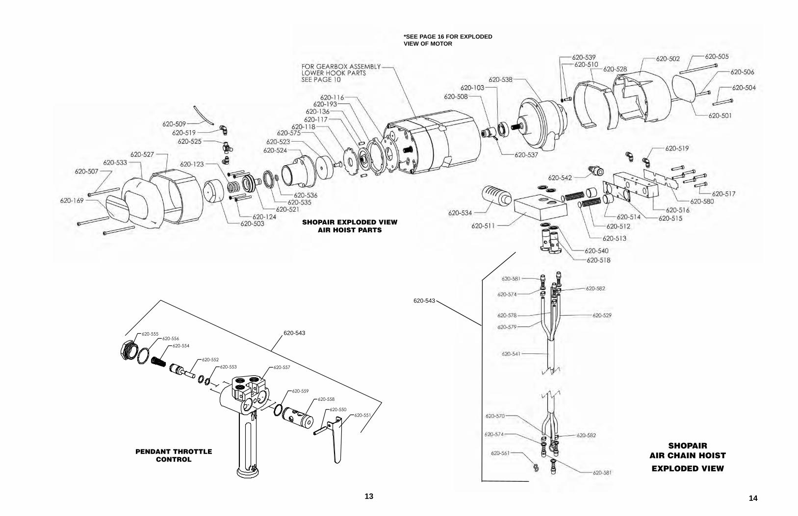
SHOPAIR EXPLODED VIEWAIR HOIST PARTS
SHOPAIRAIR CHAIN HOIST
EXPLODED VIEW
*SEE PAGE 16 FOR EXPLODEDVIEW OF MOTOR
620-556620-554
620-553 620-557
620-559
620-552
620-558
620-555
620-551620-550
620-543
620-543
PENDANT THROTTLECONTROL
15
TTRROOUUBBLLEE PPRROOBBAABBLLEE CCAAUUSSEE RREEMMEEDDYY
1. Hoist does not operate. a. Insufficient air pressure at source.b. Insufficient air supply at hoist.
c. Clogged air intake or muffler.
d. Excessive overload.
e. Clogged valve block.
f. Clogged pendant throttle control.g. Motor failure.
h. Lack of lubrication. i. Brake not operating.
a. Check and adjust air pressure.b. Use correct size air supply hose (see
page 3).c. Shut off air supply, disconnect air supply
hose and clean air filter and muffler.d. Reduce load to the rated capacity of the
hoist.e. Disassemble and check for free movement
of pistons.f. Disassemble and check parts (see page 8).g. Disassemble motor and check rotor vanes
(see page 16).h. Make sure there is oil in the lubricator.i. Make sure the air tubing to the brake are not
kinked or pinched. Disassemble brake and check for proper piston operation (see page 7). Replace worn or damaged parts.
2. Hoist will not hold load in suspension.
a. Brake not holding.b. Broken brake spring.c. Excessive overload.
a. See item 1(i).b. Replace spring.c. See item 1(d).
3. Hook will raise but will not lower or hook will lower butnot raise.
a. Clogged pendant throttle control.b. Clogged valve block.c. Excessive load.
a. See item 1(f).b. See item 1(e).c. See item 1(d).
4. Hoist looses power. a. Insufficient air pressure.b. Clogged valve block.c. Clogged muffler.d. Worn or broken rotor vanes.
a. See item 1(a).b. See item 1(e).c. Clean or replace muffler.d. Replace worn or damaged rotor vanes (see
page 9).
5. Pendant throttle control levers do not return to off position.
a. Foreign material, rust or corrosion in pendant throttle control, levers bent or lever pivot pin bent.
a. Clean pendant throttle control and replace worn or damaged parts. (see page 8).
6. Cannot regulate speed using the pendant throttle control levers.
a. Brake not operating properly.b. Pendant throttle control not
operating properly.
a. See item 1(i).b. See item 5.
7. Lifting and lowering speedsdiffer from rated speeds.
a. Incorrect air pressure or inadequateair supply.
b. Loss of power.
a. Check air pressure at hoist when hoist isoperating. (see page 3).
b. See item 1(b).
16
PENDANT THROTTLE CONTROL(Refer to Exploded View on Pages 13 & 14)
A. Disconnect the hoist from the air supply system and depress the operating levers to exhaust the air from the hoist.B. Disconnect the three air hoses from the top of the pendant throttle control.C. Remove the strain line from the top of the control handle (620-557).D. Remove the two throttle valve caps (620-555) from the back side of the control handle .E. Remove the throttle valve spring (620-554) from under each cap.F. Thread a #10-24 screw into the threaded hole in the throttle valve (620-552) and pull the valve out of the control handle.G. Clean all parts thoroughly using a mild solvent and check them for wear and damage. Check levers (620-551) for free
movement. Replace all worn or damaged parts.H. Lightly lubricate all parts and re-assemble the pendant throttle in the reverse order.I. Re-attach the air tubes to the top of the control handle and reconnect the strain line.J. Reconnect the hoist to the air supply and test for proper operation.
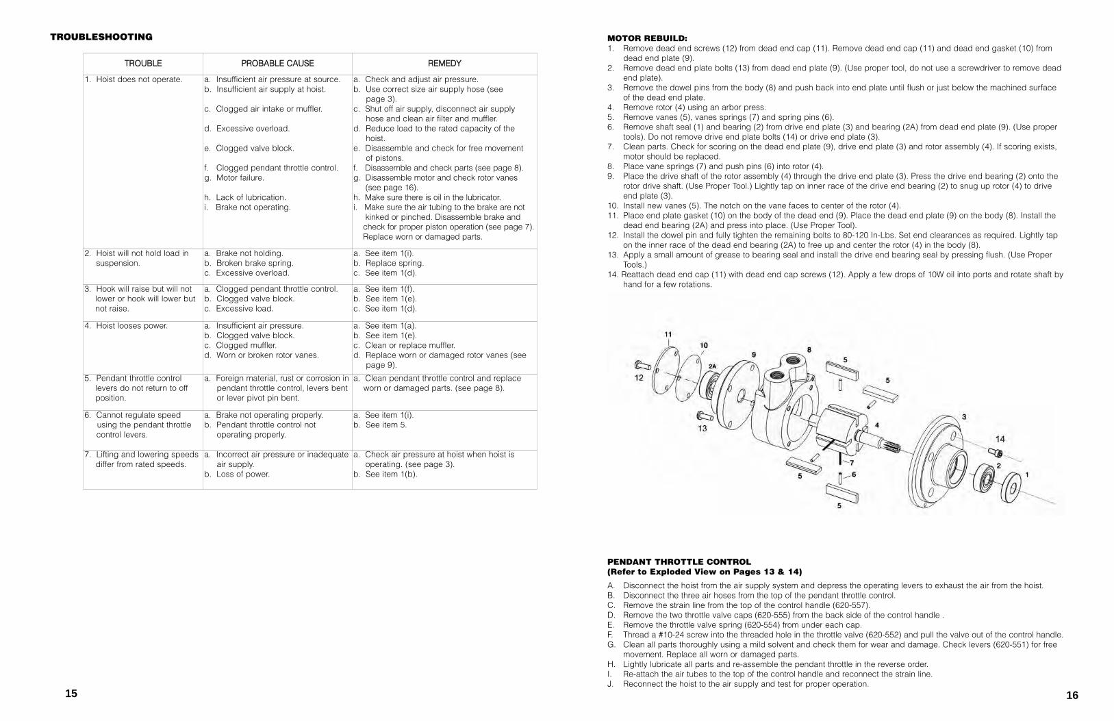
MOTOR REBUILD:1. Remove dead end screws (12) from dead end cap (11). Remove dead end cap (11) and dead end gasket (10) from
dead end plate (9).2. Remove dead end plate bolts (13) from dead end plate (9). (Use proper tool, do not use a screwdriver to remove dead
end plate).3. Remove the dowel pins from the body (8) and push back into end plate until flush or just below the machined surface
of the dead end plate.4. Remove rotor (4) using an arbor press.5. Remove vanes (5), vanes springs (7) and spring pins (6).6. Remove shaft seal (1) and bearing (2) from drive end plate (3) and bearing (2A) from dead end plate (9). (Use proper
tools). Do not remove drive end plate bolts (14) or drive end plate (3).7. Clean parts. Check for scoring on the dead end plate (9), drive end plate (3) and rotor assembly (4). If scoring exists,
motor should be replaced.8. Place vane springs (7) and push pins (6) into rotor (4).9. Place the drive shaft of the rotor assembly (4) through the drive end plate (3). Press the drive end bearing (2) onto the
rotor drive shaft. (Use Proper Tool.) Lightly tap on inner race of the drive end bearing (2) to snug up rotor (4) to drive end plate (3).
10. Install new vanes (5). The notch on the vane faces to center of the rotor (4).11. Place end plate gasket (10) on the body of the dead end (9). Place the dead end plate (9) on the body (8). Install the
dead end bearing (2A) and press into place. (Use Proper Tool).12. Install the dowel pin and fully tighten the remaining bolts to 80-120 In-Lbs. Set end clearances as required. Lightly tap
on the inner race of the dead end bearing (2A) to free up and center the rotor (4) in the body (8).13. Apply a small amount of grease to bearing seal and install the drive end bearing seal by pressing flush. (Use Proper
Tools.)14. Reattach dead end cap (11) with dead end cap screws (12). Apply a few drops of 10W oil into ports and rotate shaft by
hand for a few rotations.
TROUBLESHOOTING

NOTES
17


![[XLS] · Web viewHOIST HOIST EQUIPMENT ACTUATOR, MLG HOIST HOIST EQUIPMENT - ACTUATOR, MLG HOIST HOIST - CARDAN PIN HOIST HOIST-CARDAN PIN HOIST HOIST-DEVICE,FLAP TRACK 2-5 HOIST](https://img.pdfslide.us/doc/110x75/5b1fa5177f8b9aa64c8b4800/xls-web-viewhoist-hoist-equipment-actuator-mlg-hoist-hoist-equipment-actuator.jpg)