Embed Size (px)
Citation preview
Operating system support forwarehouse-scale computing
Malte Schwarzkopf
University of Cambridge
Computer Laboratory
St John’s College
October 2015
This dissertation is submitted forthe degree of Doctor of Philosophy


Declaration
This dissertation is the result of my own work and includes nothing which is the outcome ofwork done in collaboration except where specifically indicated in the text.
This dissertation is not substantially the same as any that I have submitted or that is being con-currently submitted for a degree, diploma, or other qualification at the University of Cambridge,or any other University or similar institution.
This dissertation does not exceed the regulation length of 60,000 words, including tables andfootnotes.


Operating system support for warehouse-scale computing
Malte Schwarzkopf
Summary
Modern applications are increasingly backed by large-scale data centres. Systems softwarein these data centre environments, however, faces substantial challenges: the lack of uniformresource abstractions makes sharing and resource management inefficient, infrastructure soft-ware lacks end-to-end access control mechanisms, and work placement ignores the effects ofhardware heterogeneity and workload interference.
In this dissertation, I argue that uniform, clean-slate operating system (OS) abstractions de-signed to support distributed systems can make data centres more efficient and secure. I presenta novel distributed operating system for data centres, focusing on two OS components: theabstractions for resource naming, management and protection, and the scheduling of work tocompute resources.
First, I introduce a reference model for a decentralised, distributed data centre OS, based on per-vasive distributed objects and inspired by concepts in classic 1980s distributed OSes. Translu-cent abstractions free users from having to understand implementation details, but enable intro-spection for performance optimisation. Fine-grained access control is supported by combiningstorable, communicable identifier capabilities, and context-dependent, ephemeral handle capa-bilities. Finally, multi-phase I/O requests implement optimistically concurrent access to objectswhile supporting diverse application-level consistency policies.
Second, I present the DIOS operating system, an implementation of my model as an extensionto Linux. The DIOS system call API is centred around distributed objects, globally resolvablenames, and translucent references that carry context-sensitive object meta-data. I illustrate howthese concepts support distributed applications, and evaluate the performance of DIOS in micro-benchmarks and a data-intensive MapReduce application. I find that it offers improved, fine-grained isolation of resources, while permitting flexible sharing.
Third, I present the Firmament cluster scheduler, which generalises prior work on schedulingvia minimum-cost flow optimisation. Firmament can flexibly express many scheduling policiesusing pluggable cost models; it makes high-quality placement decisions based on fine-grainedinformation about tasks and resources; and it scales the flow-based scheduling approach to verylarge clusters. In two case studies, I show that Firmament supports policies that reduce co-location interference between tasks and that it successfully exploits flexibility in the workloadto improve the energy efficiency of a heterogeneous cluster. Moreover, my evaluation showsthat Firmament scales the minimum-cost flow optimisation to clusters of tens of thousands ofmachines while still making sub-second placement decisions.

Acknowledgements
“I find Cambridge an asylum, in every sense of the word.”
— attributed to A. E. Housman [Ric41, p. 100].
My foremost gratitude extends to my advisor, Steve Hand, for his help and support over thecourse of the past six years. Steve’s enthusiasm, encouragement, patience, and high standardshave impacted my journey into systems research as much as they have shaped my thesis. Stevealso took the time to comment on countless drafts of this work and regularly talked to me aboutit at length, even as he himself moved between jobs and continents.
Likewise, I am grateful to Ian Leslie, my second advisor, who gave insightful feedback ondrafts of this document, and gave me the space and time to finish it to my satisfaction. In thesame vein, I am also indebted to Frans Kaashoek for his seemingly infinite patience during mylonger-than-expected “final stretch” prior to joining the MIT PDOS group.
Other current and former members of the Systems Research Group have also supported mein various ways. I am grateful to Ionel Gog, Richard Mortier, Martin Maas, Derek Murray,Frank McSherry, Jon Crowcroft, and Tim Harris for comments that have much improved theclarity of this dissertation. Moreover, I owe thanks to Robert Watson for our discussions onsecurity and capabilities, and for “adopting” me into the MRC2 project for two years; and toAnil Madhavapeddy and Andrew Moore, who assisted with equipment and feedback at keymoments.
Ionel Gog and Matthew Grosvenor deserve credit and gratitude for our close collaboration andFN07 camaraderie over the years. Our shared spirit of intellectual curiosity, rigorous experi-mentation, and lighthearted humour embodied what makes systems research enjoyable to me.
I have also been privileged to work with several enthusiastic undergraduate and master’s stu-dents: Adam Gleave, Gustaf Helgesson, Matthew Huxtable, and Andrew Scull all completedprojects that impacted my research, and I thank them for their excellent contributions.
The ideas for both systems presented in this dissertation go back to my internship at Google,where I worked with Andy Konwinski, John Wilkes, and Michael Abd-El-Malek. I thank themfor the insights I gained in our collaboration on Omega and in the Borgmaster team, which mademe realise the opportunities for innovative systems software to support the massive computeclusters deployed at internet companies.
In addition to those already mentioned above, I am grateful to my other friends in the systemsresearch community – especially Allen Clement, Natacha Crooks, Arjun Narayan, Simon Peter,Justine Sherry, and Andrew Warfield – as well as my family, whose support, opinions andcounsel have impacted my work in many ways, and who I value immensely.
Finally, I thank Julia Netter, who accompanied my PhD journey – from its very beginning tothe final proofreading of this document – with wit, insight, and loving support.

Contents
1 Introduction 19
1.1 Background . . . . . . . . . . . . . . . . . . . . . . . . . . . . . . . . . . . . 21
1.2 Contributions . . . . . . . . . . . . . . . . . . . . . . . . . . . . . . . . . . . 24
1.3 Dissertation outline . . . . . . . . . . . . . . . . . . . . . . . . . . . . . . . . 25
1.4 Related publications . . . . . . . . . . . . . . . . . . . . . . . . . . . . . . . . 27
2 Background 29
2.1 Warehouse-scale computers . . . . . . . . . . . . . . . . . . . . . . . . . . . . 30
2.2 Operating systems . . . . . . . . . . . . . . . . . . . . . . . . . . . . . . . . . 42
2.3 Cluster scheduling . . . . . . . . . . . . . . . . . . . . . . . . . . . . . . . . 55
3 A decentralised data centre OS model 63
3.1 Definitions and concepts . . . . . . . . . . . . . . . . . . . . . . . . . . . . . 64
3.2 Requirements . . . . . . . . . . . . . . . . . . . . . . . . . . . . . . . . . . . 65
3.3 Distributed objects . . . . . . . . . . . . . . . . . . . . . . . . . . . . . . . . 70
3.4 Resource naming . . . . . . . . . . . . . . . . . . . . . . . . . . . . . . . . . 73
3.5 Resource management . . . . . . . . . . . . . . . . . . . . . . . . . . . . . . 77
3.6 Persistent storage . . . . . . . . . . . . . . . . . . . . . . . . . . . . . . . . . 79
3.7 Concurrent access . . . . . . . . . . . . . . . . . . . . . . . . . . . . . . . . . 80
3.8 Summary . . . . . . . . . . . . . . . . . . . . . . . . . . . . . . . . . . . . . 82
4 DIOS: a distributed operating system for data centres 85
4.1 Abstractions and concepts . . . . . . . . . . . . . . . . . . . . . . . . . . . . 86
4.2 Objects . . . . . . . . . . . . . . . . . . . . . . . . . . . . . . . . . . . . . . 87
4.3 Names . . . . . . . . . . . . . . . . . . . . . . . . . . . . . . . . . . . . . . . 90

CONTENTS CONTENTS
4.4 Groups . . . . . . . . . . . . . . . . . . . . . . . . . . . . . . . . . . . . . . . 96
4.5 References . . . . . . . . . . . . . . . . . . . . . . . . . . . . . . . . . . . . . 99
4.6 System call API . . . . . . . . . . . . . . . . . . . . . . . . . . . . . . . . . . 103
4.7 I/O requests . . . . . . . . . . . . . . . . . . . . . . . . . . . . . . . . . . . . 106
4.8 Distributed coordination . . . . . . . . . . . . . . . . . . . . . . . . . . . . . 110
4.9 Scalability . . . . . . . . . . . . . . . . . . . . . . . . . . . . . . . . . . . . . 113
4.10 Linux integration . . . . . . . . . . . . . . . . . . . . . . . . . . . . . . . . . 114
4.11 Summary . . . . . . . . . . . . . . . . . . . . . . . . . . . . . . . . . . . . . 118
5 DIOS evaluation 119
5.1 Experimental setup . . . . . . . . . . . . . . . . . . . . . . . . . . . . . . . . 119
5.2 Performance micro-benchmarks . . . . . . . . . . . . . . . . . . . . . . . . . 120
5.3 Application benchmark . . . . . . . . . . . . . . . . . . . . . . . . . . . . . . 125
5.4 Security . . . . . . . . . . . . . . . . . . . . . . . . . . . . . . . . . . . . . . 128
5.5 Summary . . . . . . . . . . . . . . . . . . . . . . . . . . . . . . . . . . . . . 131
6 Flexible and scalable scheduling with Firmament 133
6.1 Background . . . . . . . . . . . . . . . . . . . . . . . . . . . . . . . . . . . . 134
6.2 Scheduling as a flow network . . . . . . . . . . . . . . . . . . . . . . . . . . . 137
6.3 Scheduling policies . . . . . . . . . . . . . . . . . . . . . . . . . . . . . . . . 144
6.4 Scalability . . . . . . . . . . . . . . . . . . . . . . . . . . . . . . . . . . . . . 149
6.5 Implementation . . . . . . . . . . . . . . . . . . . . . . . . . . . . . . . . . . 153
6.6 Summary . . . . . . . . . . . . . . . . . . . . . . . . . . . . . . . . . . . . . 158
7 Firmament case studies 159
7.1 Quincy cost model . . . . . . . . . . . . . . . . . . . . . . . . . . . . . . . . 159
7.2 Whare-Map cost model . . . . . . . . . . . . . . . . . . . . . . . . . . . . . . 160
7.3 Coordinated Co-location cost model . . . . . . . . . . . . . . . . . . . . . . . 164
7.4 Green cost model . . . . . . . . . . . . . . . . . . . . . . . . . . . . . . . . . 171
7.5 Summary . . . . . . . . . . . . . . . . . . . . . . . . . . . . . . . . . . . . . 174
8

CONTENTS CONTENTS
8 Firmament evaluation 177
8.1 Experimental setup . . . . . . . . . . . . . . . . . . . . . . . . . . . . . . . . 177
8.2 Decision quality . . . . . . . . . . . . . . . . . . . . . . . . . . . . . . . . . . 178
8.3 Flexibility . . . . . . . . . . . . . . . . . . . . . . . . . . . . . . . . . . . . . 189
8.4 Scalability . . . . . . . . . . . . . . . . . . . . . . . . . . . . . . . . . . . . . 192
8.5 Summary . . . . . . . . . . . . . . . . . . . . . . . . . . . . . . . . . . . . . 195
9 Conclusions and future work 197
9.1 DIOS and data centre operating systems . . . . . . . . . . . . . . . . . . . . . 198
9.2 Firmament and cluster scheduling . . . . . . . . . . . . . . . . . . . . . . . . 202
9.3 Summary . . . . . . . . . . . . . . . . . . . . . . . . . . . . . . . . . . . . . 203
Bibliography 205
A Additional background material 237
A.1 Additional workload interference experiments . . . . . . . . . . . . . . . . . . 237
A.2 CPI and IPMA distributions in a Google cluster . . . . . . . . . . . . . . . . . 243
B Additional DIOS material 245
B.1 DIOS system call API . . . . . . . . . . . . . . . . . . . . . . . . . . . . . . . 245
C Additional Firmament material 259
C.1 Minimum-cost, maximum-flow optimisation . . . . . . . . . . . . . . . . . . . 259
C.2 Flow scheduling capacity assignment details . . . . . . . . . . . . . . . . . . . 263
C.3 Quincy cost model details . . . . . . . . . . . . . . . . . . . . . . . . . . . . . 265
C.4 Flow scheduling limitation details . . . . . . . . . . . . . . . . . . . . . . . . 267
C.5 Firmament cost model API . . . . . . . . . . . . . . . . . . . . . . . . . . . . 269
9

CONTENTS CONTENTS
10

List of Figures
2.1 The Google infrastructure stack. . . . . . . . . . . . . . . . . . . . . . . . . . 31
2.2 The Facebook infrastructure stack. . . . . . . . . . . . . . . . . . . . . . . . . 32
2.3 Machine types and configurations in a Google cluster. . . . . . . . . . . . . . . 35
2.4 Micro-benchmarks on heterogeneous machine types. . . . . . . . . . . . . . . 37
2.5 Micro-architectural topologies of the systems used in my experiments. . . . . . 38
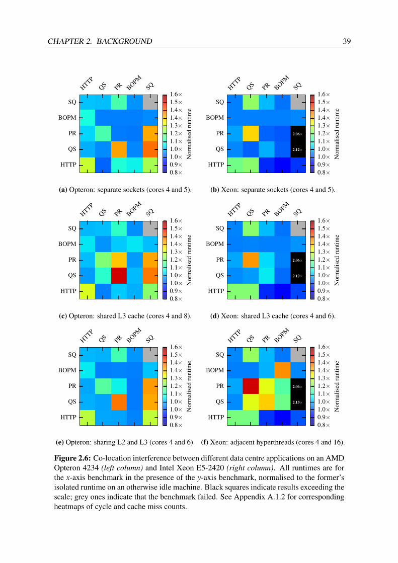
2.6 Data centre application interference on different CPU platforms. . . . . . . . . 39
2.7 Data centre application interference of batch workloads on a shared cluster. . . 41
2.8 Results of exploratory system call tracing on common data centre applications. 53
2.9 Comparison of different cluster scheduler architectures. . . . . . . . . . . . . . 57
3.1 Schematic overview of the decentralised data centre OS model. . . . . . . . . . 71
3.2 Object-based MapReduce application example. . . . . . . . . . . . . . . . . . 72
3.3 Object-based web application example. . . . . . . . . . . . . . . . . . . . . . 73
3.4 Sequence diagrams of read and write I/O requests. . . . . . . . . . . . . . . . . 81
4.1 Schematic example of different DIOS abstractions. . . . . . . . . . . . . . . . 86
4.2 A physical DIOS object and its relations to names and references. . . . . . . . . 88
4.3 Illustration of the DIOS name resolution process. . . . . . . . . . . . . . . . . 94
4.4 Illustration of the non-transitive hierarchy of DIOS groups. . . . . . . . . . . . 96
4.5 Group membership: “access-via-child” vulnerability example. . . . . . . . . . 98
4.6 Structure of a DIOS reference. . . . . . . . . . . . . . . . . . . . . . . . . . . 100
4.7 Example I/O requests with different concurrent access semantics. . . . . . . . . 107
4.8 Stages of a DIOS I/O request and transitions between them. . . . . . . . . . . . 109
4.9 Re-order matrix of DIOS system calls. . . . . . . . . . . . . . . . . . . . . . . 111
4.10 Handling an I/O request to a remote object. . . . . . . . . . . . . . . . . . . . 112

LIST OF FIGURES LIST OF FIGURES
4.11 DIOS implementation structure by example. . . . . . . . . . . . . . . . . . . . 116
5.1 Object creation latency micro-benchmark. . . . . . . . . . . . . . . . . . . . . 121
5.2 DIOS task spawn performance micro-benchmark. . . . . . . . . . . . . . . . . 122
5.3 DIOS shared-memory I/O performance. . . . . . . . . . . . . . . . . . . . . . 123
5.4 DIOS remote I/O request throughput. . . . . . . . . . . . . . . . . . . . . . . . 124
5.5 MapReduce WordCount application performance in DIOS. . . . . . . . . . . . 127
6.1 Example scheduling flow network. . . . . . . . . . . . . . . . . . . . . . . . . 138
6.2 Example flow network with capacities. . . . . . . . . . . . . . . . . . . . . . . 139
6.3 Example flow network with arc cost scopes. . . . . . . . . . . . . . . . . . . . 140
6.4 Equivalence class aggregator example. . . . . . . . . . . . . . . . . . . . . . . 143
6.5 Representation of gang scheduling requests in the flow network. . . . . . . . . 147
6.6 Examples of different Firmament multi-coordinator setups. . . . . . . . . . . . 154
6.7 High-level structure of the Firmament coordinator. . . . . . . . . . . . . . . . 155
6.8 Example Firmament flow network with machine topology information. . . . . . 156
7.1 Example flow network for the Quincy cost model. . . . . . . . . . . . . . . . . 160
7.2 Example flow network for the Whare-Map cost model. . . . . . . . . . . . . . 162
7.3 Example flow network for the CoCo cost model. . . . . . . . . . . . . . . . . . 166
7.4 Overview of the energy-aware scheduling setup. . . . . . . . . . . . . . . . . . 172
7.5 Example flow network for the Green cost model. . . . . . . . . . . . . . . . . 173
8.1 Workloads normalised runtime in Firmament cluster mix experiment. . . . . . 181
8.2 Firmament’s Whare-Map cost model learning good mappings. . . . . . . . . . 182
8.3 Task wait time with different schedulers in cluster mix experiment. . . . . . . . 184
8.4 CPI distribution for different schedulers in cluster mix experiment. . . . . . . . 184
8.5 Energy consumption for different schedulers and cost models. . . . . . . . . . 188
8.6 Energy savings obtained by auto-scaling service jobs. . . . . . . . . . . . . . . 188
8.7 Firmament scalability experiments. . . . . . . . . . . . . . . . . . . . . . . . . 193
A.1 Interference between SPEC CPU2006 workload pairs. . . . . . . . . . . . . . 238
A.2 Co-located WSC application cycle counts on different CPU platforms. . . . . . 240
12

LIST OF FIGURES LIST OF FIGURES
A.3 Co-located WSC application cache misses on different CPU platforms. . . . . . 241
A.4 n-way interference of SPEC CPU2006 benchmarks. . . . . . . . . . . . . . . . 242
A.5 CPI and IPMA distributions in the 2011 Google trace. . . . . . . . . . . . . . . 244
C.1 Example of the minimum-cost, maximum-flow optimisation problem. . . . . . 260
C.2 Example flow network with capacities. . . . . . . . . . . . . . . . . . . . . . . 264
C.3 Example flow network for the Quincy cost model. . . . . . . . . . . . . . . . . 266
13

LIST OF FIGURES LIST OF FIGURES
14
List of Tables
2.1 Machine heterogeneity micro-benchmark workloads. . . . . . . . . . . . . . . 36
2.2 Machine configurations used in the heterogeneity micro-benchmarks. . . . . . 36
2.3 Data centre applications used in pairwise interference experiments. . . . . . . . 38
2.4 Batch workloads used in scale-up interference experiment. . . . . . . . . . . . 41
2.5 Classic distributed OSes and their properties. . . . . . . . . . . . . . . . . . . 44
2.6 Local OS components and their current data centre OS equivalents. . . . . . . . 47
2.7 Comparison of classic distributed OSes and functional data centre OSes. . . . . 49
2.8 Cluster schedulers and their key design goals . . . . . . . . . . . . . . . . . . 56
3.1 Comparison of previous distributed capability schemes. . . . . . . . . . . . . . 76
4.1 Object types currently supported in DIOS. . . . . . . . . . . . . . . . . . . . . 88
4.2 A task’s capabilities depending its on relationship with a group. . . . . . . . . . 97
4.3 Example DIOS reference attributes and their properties. . . . . . . . . . . . . . 102
4.4 Current DIOS system call API. . . . . . . . . . . . . . . . . . . . . . . . . . . 104
4.5 Concurrent access semantics choices for I/O requests. . . . . . . . . . . . . . . 107
4.6 Changes made to the Linux host kernel for DIOS. . . . . . . . . . . . . . . . . 115
4.7 Binary types supported in DIOS. . . . . . . . . . . . . . . . . . . . . . . . . . 117
5.1 DIOS security properties compared to other isolation techniques. . . . . . . . . 129
6.1 Comparison of cluster scheduling, CPU scheduling, Quincy, and Firmament. . . 135
6.2 Common general costs used in Firmament’s flow network. . . . . . . . . . . . 141
6.3 Complexities of minimum-cost, maximum-flow solver algorithms. . . . . . . . 150
6.4 Task profiling metrics tracked by the Firmament coordinator. . . . . . . . . . . 157
7.1 Cost parameters in the Whare-Map cost models and their roles. . . . . . . . . . 162

LIST OF TABLES LIST OF TABLES
7.2 Summary of cost models and their features. . . . . . . . . . . . . . . . . . . . 175
8.1 Evaluation cluster and machine specifications. . . . . . . . . . . . . . . . . . . 178
8.2 Synthetic workloads used in cluster mix experiments. . . . . . . . . . . . . . . 179
8.3 Machine specifications for energy-aware scheduling experiments. . . . . . . . 186
8.4 Machine power consumption at different CPU load levels. . . . . . . . . . . . 186
8.5 Performance constraint satisfaction in the Green cost model. . . . . . . . . . . 189
8.6 Firmament’s flexibility to support existing schedulers’ policies. . . . . . . . . . 191
C.1 Edge capacity parameters for different arc types in the Quincy scheduler. . . . . 264
C.2 Cost parameters in the Quincy cost model and their roles. . . . . . . . . . . . . 266
C.3 Parameter values used in the Quincy cost model. . . . . . . . . . . . . . . . . . 267
16

Listings
4.1 DIOS object creation example. . . . . . . . . . . . . . . . . . . . . . . . . . . 92
4.2 DIOS name resolution example. . . . . . . . . . . . . . . . . . . . . . . . . . 95
4.3 DIOS reference picking example. . . . . . . . . . . . . . . . . . . . . . . . . . 101
4.4 Example of using DIOS dios_select(2) to multiplex synchronous I/O. . . . 105
4.5 Example DIOS I/O request for exclusive access to a blob. . . . . . . . . . . . . 108
4.6 Example DIOS I/O request buffer re-use in a MapReduce reducer. . . . . . . . 109
5.1 User-provided code in the DIOS MapReduce WordCount implementation. . . . 126
7.1 Excerpt of Firmament’s CoCo cost model resource fitting code. . . . . . . . . . 167
9.1 Distributed computation of fib(10) in Rust on DIOS. . . . . . . . . . . . . . 199
C.1 Firmament cost model API. . . . . . . . . . . . . . . . . . . . . . . . . . . . . 270

LISTINGS LISTINGS
18
Chapter 1
Introduction
“Go back to thinking about and building systems.Narrowness is irrelevant; breadth is relevant: it’s the essence of system.
Work on how systems behave and work, not just how they compare.Concentrate on interfaces and architecture, not just engineering.
Be courageous. Try different things; experiment.”
— Rob Pike, “Systems Software Research is Irrelevant” [Pik00, sl. 20].
Since the late 1970s, computers have moved from large “mainframes” towards ever smaller,more affordable machines and devices. Today, however, we witness the return of mainframe-like, large-scale computer data centres: “warehouse-scale” data centres composed of thousandsof commodity computers [BCH13, pp. 1–5]. These installations are required to support appli-cations that either cannot function on a single machine due to their resource demands, or whichrequire distribution to ensure service availability and fault-tolerance.
The software infrastructure of a data centre is by necessity complex, shared, and highly multi-programmed. The sensitivity of the data processed demands strong isolation between applica-tions and users, and controlled sharing of information between them. Component failures andcomplex multi-dimensional interactions between applications threaten availability of the systemand make performance unpredictable. Nevertheless, system users and programmers demand tobe shielded from this complexity: the most successful distributed systems are often those whichhide the details of distributed communication and coordination.
Resource management, sharing, and isolation are traditionally the responsibility of an operatingsystem. Operating systems have been an essential part of computing infrastructure for decades:they provide crucial abstractions, enable safe and portable use of hardware resources, supportmulti-programming, and enforce isolation between programs, users, and machine resources.
Today’s widely-deployed operating systems are designed for smartphones, laptops, and indi-vidual servers, but do not have any native abstractions for distributed operation over clustersof machines in a data centre. As their scope is limited to the local machine, such OSes fail tofulfil two key OS responsibilities: first, they are unable to name, allocate, and manage resources
19

20
outside the local machine, and second, they cannot enforce isolation between applications andusers across machines. Instead, they leave it to distributed systems software to provide thisfunctionality.
Hence, a new breed of distributed infrastructure “middleware” has emerged to provide “OS-like” functionality for data centres: cluster managers, distributed file systems, and parallel pro-gramming frameworks help users build distributed applications by providing resource manage-ment services to them. However, such software currently fails to provide the same uniform,general, and powerful abstractions that traditional single-machine OSes have long offered.
In my research for this dissertation, I have developed a reference model for a distributed datacentre operating system and prototype implementations of several of its components. In this OS,each machine is part of a larger whole: it is able to address, describe, and interact with remotedata and resources. I focus on two parts of the OS to highlight the benefits of my approach:
1. The abstractions for resource naming, access, and management. Better abstractions makedistributed systems more secure, more efficient, and easier to build.
2. The scheduling of work to compute resources. Globally optimising placement of workacross the cluster while considering its machine-level impact allows for more determinis-tic performance, increases utilisation, and saves energy.
Based on my model, I constructed two prototypes: the DIOS extensions to Linux, and theFirmament cluster scheduler. I use them to investigate the following thesis:
Better operating system support for distributed operation can improve the efficiencyand security of distributed systems in “warehouse-scale” data centres.
A clean-slate distributed data centre OS, based on uniform, translucent OS primi-tives and capability-based access control, implements efficient and secure resourcemanagement, while running prototypical distributed applications at performancecomparable to, or better than, current OSes and data centre “middleware”.
A cluster scheduler that combines distributed cluster state and fine-grained localmachine information additionally improves performance determinism and energyefficiency of the data centre, and is sufficiently flexible to extend to other policies.
In the next section, I explain the background of today’s commodity operating systems and datacentre “middleware”, outline why a new distributed data centre OS can improve upon both, andpoint out related recent research efforts (§1.1). Following, I state my contributions described inthis dissertation (§1.2) and outline its overall structure (§1.3). Finally, I list prior publicationsof the work described and related projects that have impacted it (§1.4).

CHAPTER 1. INTRODUCTION 21
1.1 Background
As computing devices become ever smaller, cheaper, and more ubiquitously connected to the In-ternet, applications’ server-side back-ends now rely on access to enormous repositories of data,or on computations that exceed the abilities of the local device or a single server. Such back-endservices run in the large-scale data centres operated by internet companies like Google, Ama-zon, Yahoo!, Facebook, Twitter, or Microsoft. Request processing in these data centres involvesmultiple distributed systems that extend over thousands of individual server machines.
Individual machines in these data centres merely contribute resources to a large pool: they mayjoin, leave, or fail at any time. While many different applications and users share the datacentre’s machines, it is often conceptually abstracted as a single machine of very large capacityto the programmer. This notion is somewhat akin to that of a time-shared mainframe, andreferred to as a “warehouse-scale computer” (WSC) [BCH13, pp. 2–5].
Within a single machine, the functionality of resource virtualisation, sharing, naming, and man-agement is provided by its operating system. Indeed, the local abstractions for this purposehave a long history: many of today’s pre-eminent operating system paradigms and abstractionsoriginated with the first versions of Unix in the early 1970s. Unix was developed for the then-emergent “minicomputers” [RT74], rather than the mainframes that large operations favoured atthe time, and inspired widely-used contemporary systems such as GNU/Linux, the BSD family,and Windows. Unlike mainframe operating systems, which were designed to deal with large,shared installations with multiple independent components that might fail, these OSes focussolely on managing a single machine with shared memory and I/O hardware.
One might expect the operating system of a “warehouse-scale computer” to be more similar to amainframe OS than to the single-machine operating systems. However, the individual machineslocally run standard server operating systems – typically variants of Linux, BSD, or Windows.Instead of extending these OSes, a new class of systems software for data centres has emerged:distributed infrastructure systems built to offer distributed variants of operating system servicesto distributed applications. This “middleware” forms the WSC OS and includes systems that,individually, provide distributed coordination, distributed file systems, distributed process andresource management, and distributed parallel programming frameworks. Indeed, industrialpackage management and deployment systems – e.g. Mesosphere DC/OS1 – are advertised asa “data centre operating system”, since they provide abstractions on top of which applicationprogrammers build their distributed applications.
However, the use of commodity OSes combined with several, individually single-purpose dis-tributed “middleware” components has drawbacks:
1. Complex mapping of disjoint abstractions: abstractions for state and data differ bothbetween the local OS and the distributed systems (e.g. file descriptors, sockets, and mem-ory mappings vs. UUIDs, RPC callbacks, and resilient distributed datasets [ZCD+12]),
1See https://dcos.io/; accessed 10/05/2016.

22 1.1. BACKGROUND
and between different distributed systems (e.g. HDFS ACLs [SKR+10] vs. key-value storeidentifiers [CDG+06] vs. cluster-level access control [VPK+15]).
This requires extensive translation between abstractions, which reduces efficiency, im-pacts scalability, and complicates tracing and debugging.
2. Lack of specialisation: commodity operating systems are designed to support use casesfrom interactive desktops to highly-loaded servers. Many of their abstractions and tech-niques used are compromises for generality, rather than a good fit for the specific use caseof a data centre.
This leads to inefficiency when a specialised approach could utilise contextual informa-tion (e.g. a buffer cache for distributed objects) or offer better security (e.g. mandatorycompartmentalisation or distributed data-flow tracking).
3. Poor access restrictions: the data centre is a multi-tenant environment and users mayaccidentally or deliberately run malicious code. Operators currently use virtualisationtechniques, such as containers, and virtual machines to restrict access and contain attacks,but these techniques are coarse-grained and make delegation difficult.
This complicates isolation across applications (e.g. compartmentalisation such that aprogram may only legitimately access its inputs), and delegation of work to restricted-privilege helpers (e.g. limiting access to other systems, such as a key-value store).
4. Segregated scheduling: machine-level scheduling decisions (in the local OS) are decou-pled from global task scheduling (in a cluster-scheduler).
This results in poor control over work placement as the different scheduling levels fail toexchange information to avoid inefficiencies (e.g. negative co-location interference).
Improving the distributed operating system and its abstractions can help address these draw-backs, for example by introducing more uniform resource management and access control.Consequently, it might prove insightful to consider what a clean-slate OS for a data centreshould look like.
Indeed, others have made similar observations:
• Zaharia et al. note the need for “operating system” abstractions in the data centre, requiredto support a growing set of distributed applications [ZHK+11].
• Maas et al. envision a holistic language runtime that transcends machine boundaries andtakes the place of the operating system [MAH+14].
However, the idea of a distributed OS with uniform abstractions is not itself new. In the 1980s,researchers experimented with distributed OS-level primitives, but these failed to see adoptionoutside academic research, and consequently the current, “middleware-based” data centre OSes

CHAPTER 1. INTRODUCTION 23
evolved. Why should we nevertheless look into better distributed operating system abstractions,rather than sticking with what we have?
A key reason why the distributed OS concept is timely again is that distributed operation is anecessity in warehouse-scale data centres, rather than – as in the 1980s – an option useful onlyto some workloads. Additionally, there are several advantages to a coherent distributed OS overan ad-hoc combination of heterogeneous middleware systems:
1. The operating system’s abstractions set the rules by which ultimately all applicationshave to abide: in the absence of bugs, its abstractions are impossible to bypass (evenmaliciously).
2. An OS virtualises resources and may thus present a different, yet internally consistent,view of the system to each application.
3. The OS abstractions are uniform across applications, since they are designed to beapplication-agnostic primitives, and they are available to any application.
4. The privileged OS has an elevated, omniscient view of resource allocation, and canhence make better decisions than individual programs can on their own.
A new, clean-slate data centre OS might complement the efficiency gains that custom-builtphysical data centre infrastructure, custom machine chassis, rack, and cooling equipment al-ready grant to data centre operators [BCH13, pp. 47–65; WSK+09]. Indeed, Google alreadycustomise Linux extensively [WC09]; the effort involved in building a new OS is likely accept-able to such large organisations.
Indeed, research efforts increasingly attempt to shake up the established OS abstractions andre-think the role of the operating system:
• Corey makes OS abstractions scalable to many CPU cores by using per-core data struc-tures by default, with all sharing being explicit and application-driven [BCC+08]. Coreyfocuses on single-machine scalability, but similar selective sharing approaches can ensurescalability in distributed systems.
• fos is a single system image (SSI) OS for many-core machines and cloud deployments,based on message passing between “factored” servers that offer OS services [WGB+10].Each core runs a simple micro-kernel and OS services consist of multiple spatially sched-uled instances, making replication and fine-grained locality explicit.
• Barrelfish [BBD+09] is a new OS designed for heterogeneous and potentially non-cache-coherent many-core systems. Based on the premise that scalable operating systems mustapply distributed systems techniques [BPS+09], it performs inter-process communicationover a range of different channels, including across machines [HGZ11].

24 1.2. CONTRIBUTIONS
• The Akaros operating system reduces the transparency of virtualisation, maximising theexposition of system information to applications [RKZ+11]. It provides gang-scheduledmulti-core processes (MCPs) that allow applications to enact their own scheduling poli-cies in order to improve the overall efficiency of the system.
• Tesselation gives Quality-of-Service (QoS) guarantees to applications using space-timepartitioning [CEH+13] and performs two-level scheduling (like Akaros). Its resourcepartitioning along with continuous statistics monitoring counters interference betweenco-located applications at the OS level.
• nonkernel [BPA+13], Arrakis [PLZ+14], and IX [BPK+14] remove the OS from thecritical path of I/O-intensive operations (“data plane”), and permit applications to interactdirectly with hardware for improved scalability and performance.
• The Andromeda design of “a massively distributed operating system [...] for the com-modity cloud” [VKS15] envisages a fully transparent distributed OS based on a minimalpico-kernel and with migratable “fibril” tasks that communicate via unidirectional chan-nels.
My work proposes a new distributed OS model, specialised to the domain of warehouse-scaledata centres. In doing so, it draws on many of the above, as well as on historic distributedoperating systems (§2.2.1). DIOS, my prototype implementation, is a single system imageoperating system (like fos and Andromeda), emphasises scalable abstractions (like Corey andBarrelfish), and externalises policy to applications (like Akaros and Tesselation).
1.2 Contributions
This dissertation describes three principal contributions:
1. My first contribution is a model for a decentralised, distributed operating system fordata centres, based on uniform, clean-slate OS abstractions that improve the efficiencyand security of distributed applications. This decentralised data centre OS model is builtaround pervasive distributed objects, and relies on storable and communicable identi-fiers to name and discover resources. Once discovered, resource management relies ontranslucent handles that form delegatable capabilities, which can be introspected uponto improve application performance and fault tolerance. To allow flexible concurrent ac-cess to objects without implicit synchronisation, the model supports transaction-like I/Orequests.
2. My second contribution is the DIOS prototype, which implements the decentralised datacentre OS model by extending Linux. DIOS is based on typed objects, which are named,

CHAPTER 1. INTRODUCTION 25
accessed, and managed via distributed capabilities. DIOS implements the decentraliseddata centre OS model’s identifiers as globally unique names resolved via a distributedkernel name service, while references implement translucent handles as segregated capa-bilities. Moreover, DIOS has a new system call API for interaction with local and remoteobjects based on scalable design principles, and supports I/O requests with flexible con-current access semantics. Finally, I describe how DIOS integrates with Linux to achievebackwards-compatibility with existing applications.
3. My third contribution is the Firmament cluster scheduler. I generalise the approachtaken by Quincy [IPC+09], which models the scheduling problem as a minimum-cost op-timisation over a flow network. I show that this generalisation allows the flow-optimisationapproach to flexibly express desirable scheduling policies not supported by Quincy. I alsodemonstrate that – contrary to common prior belief – the flow-optimisation approach isscalable to warehouse-scale clusters. Firmament is implemented as a cluster manager andtracks detailed task profiling and machine architecture information. In three case studies,I implemented Firmament scheduling policies that consider machine heterogeneity, avoidtask co-location interference, and increase data centre energy efficiency.
All models, algorithms, and implementations described are results of my own work, and I builtthe DIOS and Firmament implementations from scratch. However, colleagues and studentsin the Computer Laboratory have at times assisted me in extending and evaluating specificprototype components.
In particular, Matthew Grosvenor and I sketched an initial version of the DIOS system callAPI together, and Andrew Scull contributed the ELF branding for DIOS binaries (§4.10.3) andported the Rust runtime to DIOS (§9.1.1) during his Part II project in the Computer Science Tri-pos [Scu15]. Ionel Gog implemented the flowlessly minimum-cost, maximum-flow solverfor Firmament (§6.4.3), and Gustaf Helgesson implemented and evaluated Firmament’s Greencost model (§7.4) under my supervision during his MPhil in Advanced Computer Science. Fi-nally, Adam Gleave investigated incremental minimum-cost, maximum-flow solvers and therelaxation algorithm (§6.4.3) in his Part II project under my supervision [Gle15].
1.3 Dissertation outline
This dissertation is structured as follows:
Chapter 2 surveys background and related work for three areas covered by my work: “warehouse-scale” data centres, operating systems, and cluster scheduling. I explain the softwareinfrastructure of modern data centres, and show that hardware heterogeneity and task co-location interference hamper performance predictability. I then consider operating sys-tems, survey classic distributed OSes and the current data centre software, and highlight

26 1.3. DISSERTATION OUTLINE
key deficiencies with the latter. Finally, I give an overview of the state of the art in clusterscheduling.
Chapter 3 introduces a reference model for resource naming and management in a decen-tralised, distributed data centre operating system. I enumerate the requirements this modelmust satisfy, explain its foundation in distributed objects, introduce the notion of translu-cent abstractions, and show how storable and communicable identifier capabilities andcontextual handle capabilities are sufficient to enact fine-grained access control. Finally,I explain how the model stores objects persistently, and how I/O requests enable concur-rent I/O without implicit synchronisation.
Chapter 4 introduces DIOS, a prototype implementation of my model as an extension to Linux.I describe the key primitives and interfaces of DIOS: names, references, groups, and tasks.I outline the DIOS system call API, explain how machines coordinate with each other,discuss the scalability of the DIOS abstractions, and finally explain how the seamlessintegration with Linux enables incremental migration to DIOS.
Chapter 5 evaluates DIOS using micro-benchmarks of OS-level primitives and an exampleapplication. I show that DIOS runs distributed applications at comparable performance tocurrent systems and compare and contrast the security properties of the DIOS abstractionswith widely-used isolation techniques.
Chapter 6 describes my Firmament cluster scheduler. I show how Firmament generalises theQuincy scheduler [IPC+09] and how its pluggable cost models flexibly express schedul-ing policies. I discuss how the underlying minimum-cost, maximum-flow optimisationproblem can be solved incrementally in order to scale the flow network optimisation ap-proach to large data centres, and finally describe how Firmament is implemented as acluster manager.
Chapter 7 describes three cost models for Firmament that I implemented as case studies: thefirst avoids co-location interference by monitoring micro-architectural performance coun-ters, the second also respects a multi-dimensional resource model, and the third improvesenergy efficiency in heterogeneous clusters.
Chapter 8 evaluates Firmament, investigating the effectiveness of its scheduling decisions us-ing real-world test-bed deployments, Firmament’s ability to flexibly express differentscheduling policies, and its scalability to large clusters and a simulated Google workload.
Chapter 9 points out directions for future work and concludes my dissertation. In particular,I focus on the accessibility of DIOS abstractions for the programmer, on deeper local OSkernel changes motivated by DIOS, and on techniques to further improve security. I alsodiscuss how Firmament might be extended to cover more heterogeneous systems.
CHAPTER 1. INTRODUCTION 27
1.4 Related publications
Parts of the work described in this dissertation have been covered in peer-reviewed publications:
[GSG+16] Ionel Gog, Malte Schwarzkopf, Adam Gleave, Robert N. M. Watson, and StevenHand. “Firmament: fast, centralized cluster scheduling at scale”. In: Proceedings of the12th USENIX Symposium on Operating Systems Design and Implementation (OSDI). Toappear. Savannah, Georgia, USA, Nov. 2016.
[SGH13] Malte Schwarzkopf, Matthew P. Grosvenor, and Steven Hand. “New Wine in OldSkins: The Case for Distributed Operating Systems in the Data Center”. In: Proceedingsof the 4th Asia-Pacific Systems Workshop (APSYS). Singapore, July 2013, 9:1–9:7.
[SH12] Malte Schwarzkopf and Steven Hand. “A down-to-earth look at the cloud host OS”.in: Proceedings of the 1st Workshop on Hot Topics in Cloud Data Processing (HotCDP).Bern, Switzerland, Apr. 2012, 3:1–3:5.
[SMH11] Malte Schwarzkopf, Derek G. Murray, and Steven Hand. “Condensing the cloud:running CIEL on many-core”. In: Proceedings of the 1st Workshop on Systems for FutureMulticore Architectures (SFMA). Salzburg, Austria, Apr. 2011.
I have also authored or co-authored the following publications, which have impacted the workpresented in this dissertation, but did not directly contribute to its contents:
[GSG+15] Matthew P. Grosvenor, Malte Schwarzkopf, Ionel Gog, Robert N. M. Watson, An-drew W. Moore, Steven Hand, and Jon Crowcroft. “Queues don’t matter when you canJUMP them!” In: Proceedings of the 12th USENIX Symposium on Networked SystemsDesign and Implementation (NSDI). Oakland, California, USA, May 2015.
[GSC+15] Ionel Gog, Malte Schwarzkopf, Natacha Crooks, Matthew P. Grosvenor, Allen Cle-ment, and Steven Hand. “Musketeer: all for one, one for all in data processing systems”.In: Proceedings of the 10th ACM European Conference on Computer Systems (EuroSys).Bordeaux, France, Apr. 2015.
[SKA+13] Malte Schwarzkopf, Andy Konwinski, Michael Abd-El-Malek, and John Wilkes.“Omega: flexible, scalable schedulers for large compute clusters”. In: Proceedings of the8th ACM European Conference on Computer Systems (EuroSys). Prague, Czech Republic,Apr. 2013, pp. 351–364.
[SMH12] Malte Schwarzkopf, Derek G. Murray, and Steven Hand. “The Seven Deadly Sinsof Cloud Computing Research”. In: Proceedings of the 4th USENIX Workshop on HotTopics in Cloud Computing (HotCloud). Boston, Massachusetts, USA, June 2012, pp. 1–6.

28 1.4. RELATED PUBLICATIONS
[MSS+11] Derek G. Murray, Malte Schwarzkopf, Christopher Smowton, Steven Smith, AnilMadhavapeddy, and Steven Hand. “CIEL: a universal execution engine for distributeddata-flow computing”. In: Proceedings of the 8th USENIX Symposium on NetworkedSystem Design and Implementation (NSDI). Boston, Massachusetts, USA, Mar. 2011,pp. 113–126.

Chapter 2
Background
Many modern applications – directly or indirectly – depend on distributed systems runningin large-scale compute clusters situated in data centres. These data centres conceptually form“warehouse-scale computers”, since the details of their operation are abstracted away from boththe end-user and the application programmer [BCH13].
Like most modern computers, warehouse-scale data centre “machines” have an extensive sys-tems software stack, though one that uniquely includes distributed systems software. Roughly,it contains three types of software:
Local operating system kernels interface between local machine hardware and higher-level,hardware-independent software. Operating system kernels enforce isolation, arbitratemachine resources, and locally perform privileged operations on behalf of other software.
Distributed infrastructure systems are user-space applications that run on many or on all ma-chines in the WSC, and which collectively form the “operating system” of the data centre.Many of their services are distributed versions of classic OS functionality, such as datastorage, scheduling, or coordination of computations.
User applications implement the functionality exposed to end-users of the data centre, relyingon the services and abstractions offered by the distributed infrastructure systems. Theyare managed by a dedicated infrastructure system, the “job master” or “cluster manager”.
In this chapter, I survey how this distributed software stack is realised in current data centres, andmotivate the opportunity for a more uniform, secure and efficient design of two key components,resource management and the cluster scheduler.
In Section 2.1, I describe the make-up of today’s warehouse-scale data centres. I first describethe roles of typical distributed infrastructure systems and the applications executed atop them(the “workload”). I then discuss several challenges posed by the data centre environment: un-precedented scale, a need for high utilisation in the face of hardware and workload heterogene-ity, and consequent performance variance due to co-location interference between applications.
29

30 2.1. WAREHOUSE-SCALE COMPUTERS
Following, Section 2.2 considers the role of the operating system in a WSC-style data centre.I compare the software that currently functions as the operating system of a WSC to classicdistributed operating systems of the 1980s, and explain why revisiting some of their key ideascan benefit modern warehouse-scale data centres.
Finally, I focus on the cluster scheduler, a particularly crucial distributed infrastructure com-ponent in current data centre “operating systems”. Section 2.3 discusses the design goals for acluster scheduler and surveys the extensive work of recent years in this area, highlighting thechallenges that my work addresses.
2.1 Warehouse-scale computers
To increase cluster utilisation, multiple applications and users typically share the cluster thatconstitutes a “warehouse-scale computer” [HKZ+11; VPK+15]. The WSC cluster runs manyindependent tasks – instantiated as processes, containers, or virtual machines – that belong todifferent applications. Executing the resulting “workload mix” efficiently and isolating appli-cations from each other is key to the efficient and secure operation of a warehouse-scale datacentre.
In this section, I describe the typical workload in a warehouse-scale data centre (§2.1.1), outlinehow heterogeneity in its constituent hardware matters (§2.1.2), and how high utilisation comesat the cost of interference that degrades workload performance (§2.1.3).
2.1.1 Workloads
WSCs exist to support workloads that require large amounts of compute and storage resources.Distribution over many machines is required either to keep up with a large number of userrequests, to perform parallel processing in a timely manner, or to be able to tolerate faultswithout disruption to end-user applications (e.g. mobile or web front-ends).
In general, the “workload” of such a data centre falls into two categories: infrastructure systems(§2.1.1.1) that provide essential services and user applications that process data or expose themto remote end-users (§2.1.1.2).
In addition, workloads can also often be divided into batch and service work (as, e.g., atGoogle [SKA+13]). This division is orthogonal to the split into infrastructure systems andapplications, although most infrastructure systems are service workloads.
Service workloads run continuously, offering functionality either directly to end-users or toend-user-facing applications. They only terminate due to failure, or human or clusterscheduler intervention. A distributed key-value store is an example of a service workload.

CHAPTER 2. BACKGROUND 31
Chubby [Bur06]locking and coordination
Borg [VPK+15] and Omega [SKA+13]cluster manager and job scheduler
coordination & cluster management
Dapper [SBB+10]pervasive tracing
CPI2 [ZTH+13]interference mitigationm
onito
ring
tool
s
GFS/Colossus [GGL03]distributed block store and file system
BigTable [CDG+06]row-consistent multi-dimensional sparse map
MegaStore [BBC+11]cross-DC ACID database
Spanner [CDE+13]cross-DC multi-version DB
Dremel [MGL+10]columnar database
data storage
MapReduce [DG08]parallel batch processing
FlumeJava [CRP+10]parallel programming
Tenzing [CLL+11]SQL-on-MapReduce
Percolator [PD10]incremental processing PowerDrill [HBB+12]
query UI & columnar store
MillWheel [ABB+13]stream processing
Pregel [MAB+10]graph processing
data processing
Figure 2.1: The Google infrastructure stack. I omit the F1 database [SOE+12], the back-end of which was superseded by Spanner, and unknown or unpublished front-end servingsystems. Arrows indicate data exchange and dependencies between systems; “layering”does not imply a dependency or relation.
Batch workloads are finite data processing jobs that start, perform some work, and terminatewhen completed. An example of a batch workload is a regularly executed log crawlingand transformation pipeline.
Empirically, the majority of jobs and tasks are typically in batch jobs, but the majority of clusterresources over time are devoted to service jobs [SKA+13, §2].
Classification into the batch and service categories does not per se imply a priority order. How-ever, service workloads are more likely to have high priorities, since their operation is essentialto serving end-user requests and to keeping other applications operational.
It is also worth noting that most service jobs (and most infrastructure systems) are request-oriented, online transaction processing (OLTP) type workloads (even though they need not ex-plicitly use transactions). Batch workloads, by contrast, are often online analytical processing(OLAP) workloads, have less rigid request structure, and tolerate higher response latencies.
2.1.1.1 Distributed infrastructure systems
Infrastructure systems are key to the operation of data centre applications. They often serve thesame purpose as OS services traditionally implemented in the kernel. For example, they offercoordination, storage and file systems, and process-like abstractions, that higher-level applica-tions build upon. As a result, new “stacks” of mutually dependent infrastructure systems have

32 2.1. WAREHOUSE-SCALE COMPUTERS
ÜberTrace [CMF+14, §3]pervasive tracing
MysteryMachine [CMF+14]performance modeling
monitoring toolsparallel data processing
HDFS [SKR+10]distributed block store and file system
MySQLsharded ACID database
Bistro [GSW15]cluster scheduler
HBase [BGS+11]multi-dimensional sparse map
f4 [MLR+14]warm blob storage
Haystack [BKL+10]hot blob storage
memcached [NFG+13]in-memory key-value store/cache
TAO [BAC+13]graph store
Wormhole [SAA+15]pub-sub replication
data storage
(Hadoop) MapReduce [DG08]parallel batch processing
Hive [TSA+10]SQL-on-MapReduce
Peregrine [MG12]interactive querying
Scuba [AAB+13]in-memory database
Unicorn [CBB+13]graph processing
Figure 2.2: The Facebook infrastructure stack. No single cluster manager for a sharedsubstrate analogous to Google’s Borg and Omega is known; it is unclear if schedulers likeBistro deal with all workloads. Arrows indicate data exchange and dependencies betweensystems; “layering” does not imply a dependency or relation.
been created. Figures 2.1 and 2.2 illustrate this using the known components of the distributedinfrastructure software stacks at Google and Facebook.
Broadly speaking, the infrastructure stacks typically consist of coordination and cluster man-agement services, storage services, and parallel data processing frameworks.
Coordination and cluster management. Many data centre infrastructure services are co-dependent and require an authoritative source of configuration information to coordinate.
This coordination authority is usually implemented as a reliable, consistent distributed key-value store. This store records the locations of master processes (leaders), offers distributedlocking, and enables service discovery by tracking the location of service tasks. Google’sChubby service [Bur06] for this purpose is based on the Paxos consensus algorithm [CGR07].Yahoo!’s Zookeeper [HKJ+10], which is based on Zab [RJ08], and etcd, which is based onRaft [OO14], are similar open-source coordination services. All of these use distributed con-sensus algorithms that trade raw performance for reliability in the face of failures.
A cluster manager, by contrast, manages service and application tasks and arbitrates resourcesbetween them. This entails tracking machine liveness, starting, monitoring, and terminat-ing tasks, and using a cluster scheduler to decide on task placements. Mesos [HKZ+11] andGoogle’s Borg [VPK+15] and Omega [SKA+13] are such cluster managers. Task schedulingdecisions are made as part of the cluster manager, although not all deployments use a single,unified cluster manager. Instead, some data centres are partitioned into single-purpose sub-clusters, each with an independent cluster scheduler. I will review these and other schedulerarchitectures in Section 2.3.1.

CHAPTER 2. BACKGROUND 33
Data storage. Warehouse-scale data centres store huge amounts of data, but use differentinfrastructure systems for this purpose, depending on the data access frequency and structure.
Block storage either comes in the form of unstructured stores, or as hierarchical file systemsakin to networked or local file systems. Facebook’s Haystack [BKL+10] and f4 [MLR+14] areunstructured stores which store and replicate binary large objects (blobs) of different popularity.By contrast, GFS [GGL03] and its successor Colossus at Google, the Hadoop Distributed FileSystem (HDFS) at Facebook and Yahoo!, and TidyFS [FHI+11] and Flat Datacenter Storage(FDS) [NEF+12] at Microsoft, are hierarchical distributed file systems.
For more structured data, data centres run sharded, replicated key-value stores that make vary-ing trade-offs between consistency and performance. BigTable [CDG+06] implements a three-dimensional map indexed by a row, column, and timestamp on top of GFS and offers per-rowconsistency; Facebook uses HBase over HDFS [HBD+14] in a similar way to store users’ mes-sages [BGS+11]. Other data stores are closer to traditional databases and offer transactionswith ACID guarantees: examples are Google’s Megastore [BBC+11] over BigTable, and Span-ner [CDE+13]. In some cases, classic sharded and replicated databases are used, too: Facebook,for example, uses MySQL for structured long-term storage.
For expedited access by request-serving applications, data are often cached in ephemeral stores.These stores can be generic key-value stores – like memcached, which is used as the in-memoryserving tier at Facebook [NFG+13] – or specifically designed for particular use-cases. Google’sDremel [MGL+10] and PowerDrill [HBB+12], for example, store data in columnar form toenable fast aggregation queries, while Facebook’s Tao [BAC+13] is a cache for graph-structureddata with locality.
Parallel data processing. Some analytics applications often need to process very large datasets in a timely manner. In order to expose an accessible programming interface to non-expertapplication programmers, parallel data processing frameworks hide challenging aspects of dis-tributed programming. Examples of the details abstracted include fault tolerance, scheduling,and message-based communication.
MapReduce [DG08] is a widely-used abstraction for such transparent distributed parallelism.Its relative simplicity – the user only has to implement a map() and a reduce() function– makes it an appealing abstraction. Other frameworks are more expressive: for example,Dryad [IBY+07] at Microsoft models the computation as a data-flow graph.
Even higher-level abstractions are deployed on top of the data processing frameworks in orderto make them accessible to lay users: common examples are domain-specific languages, suchas the SQL-like Tenzing [CLL+11] at Google, and Hive [TSJ+09] at Facebook, or languageintegration (e.g. FlumeJava at Google [CRP+10] and DryadLINQ at Microsoft [YIF+08]), orinteractive UIs like Facebook’s Scuba [AAB+13].
For some applications, purpose-built systems perform specialised processing: for example, Per-colator at Google was built specifically for fast incremental updates to the web search index in

34 2.1. WAREHOUSE-SCALE COMPUTERS
BigTable [PD10]. Likewise, streaming data is processed with special stream processing frame-works such as MillWheel [ABB+13] at Google, S4 at Yahoo! [NRN+10], and Storm [TTS+14]and its successor, Heron [KBF+15], at Twitter. Graph structured data is processed using sys-tems which let users express computations in a “vertex-centric” way, with Unicorn [CBB+13]at Facebook and Pregel [MAB+10] at Google being well-known examples.
Monitoring and tracing. The complex interactions between the aforementioned infrastruc-ture systems require bespoke performance tracing and debugging tools, since events from manydifferent machines and contexts must be correlated.
Such tools either hook into pervasively used communication libraries, as in Google’s Dap-per [SBB+10] or Twitter’s Finagle [Eri13], or leverage common identifiers to construct a cross-system request trace, as in Facebook’s ÜberTrace [CMF+14, §3]. The large corpus of tracingdata available enables statistical analysis to derive causal relationships (e.g. in Facebook’s Mys-tery Machine [CMF+14]), or to detect performance anomalies such as negative interferencebetween co-located tasks (e.g. in Google’s CPI2 [ZTH+13]).
2.1.1.2 Applications and user jobs
Applications form the “business logic” of the data centre: they serve end user requests, analysedata to derive insights, or support other productivity tasks.
For example, Facebook’s web server instances respond to end user requests by aggregatingelements from the TAO, memcached, Haystack and f4 storage systems into a response. At thesame time, Hive queries run MapReduce jobs that analyse the same data to collect informationon user behaviour, and long-running MapReduce jobs move data between storage systems.Similar setups exist in other companies.
Such applications and user jobs differ from infrastructure services in three ways:
1. Applications generally rely on libraries that interact with the infrastructure systems, ratherthan interfacing directly with the local OS kernel, as most infrastructure systems do.
2. High performance and low latency are important to some applications (e.g. serving front-ends), but not to others (e.g. batch jobs), while almost all infrastructure services are sub-ject to latency bounds as part of a service level objective (SLO).
3. Application developers use high-level languages [MAH+14], and rely on higher-level in-terfaces than used for constructing infrastructure systems; as a result, application code isignorant of the details of machines, coordination, and parallelisation.
Since the applications are merely consumers of APIs provided by the infrastructure systems,changes to the underlying operating system – either in the local OS kernel, or in the distributedinfrastructure components – can be entirely invisible to the application programmers. Sec-tion 2.2.5 and later chapters will return to this observation.

CHAPTER 2. BACKGROUND 35
3195311727031331521
32
21018818382
1160517371744351
152757411210931817
186280115456311339311322601613
116165427816503
1
32
2912535
121
12583machines
platformspecificationattributes
Figure 2.3: Sankey diagram of machine types and configurations in the public mid-2011Google cluster trace [RWH11]. The cluster is heterogeneous: the 12,583 machines becom-ing increasingly fragmented when differentiated by platform, specification, and attributes.1
2.1.2 Hardware heterogeneity
Warehouse-scale data centres are typically composed of machines purchased in bulk, sincethis allows for economies of scale in purchasing. However, in practice, the machine mix isheterogeneous due to rolling hardware upgrades and deliberate diversification.
For example, the cluster in the public trace released by Google in 2011 [RWH11; Wil11], con-sists of around 12,550 machines, which cover three different machine platforms and ten differ-ent machine specifications. Once other distinguishing attributes of a machine – such as “kernelversion, clock speed, presence of an external IP address”, or “whether [the] machine runs aGFS chunkserver” [RWH11, p. 5] – are considered, the number of unique combinations growsto 34. Of these combinations, eight apply to more than 100 machines, and thirteen apply to tenor more machines (Figure 2.3). Anecdotal evidence from other data centres, such as Amazon’sEC2 infrastructure, confirms that this heterogeneity generalises [OZN+12]. Moreover, it mat-ters for performance: Google have observed varying performance characteristics of identicalworkloads on different machine platforms [TMV+11].
1The trace documentation defines machine platform as the combination of “microarchitecture and chipset ver-sion” [RWH11, p. 5]; in addition, I regard the specification of a machine to refer to its platform and its capacity,the latter being the number of cores and the total RAM [RWH11, p. 5].
2http://www.coker.com.au/bonnie++/; accessed on 05/01/2015.3https://iperf.fr/; accessed on 05/01/2015.4init/calibrate.c in the Linux kernel source; see http://lxr.free-electrons.com/
source/init/calibrate.c?v=3.14; accessed on 05/01/2015.

36 2.1. WAREHOUSE-SCALE COMPUTERS
Benchmark Description Referencehmmer Hidden Markov model gene database search (integer) [Hen06, p. 5]gromacs Molecular dynamics simulation (floating point) [Hen06, p. 11]STREAM DRAM memory throughput benchmark. [McC95]NUMA-STREAM Multi-threaded version of STREAM for machines
with multiple memory controllers.[Ber11]
bonnie-rd Disk read throughput measurement from thebonnie++ benchmarking tool.
See footn.2
bonnie-wr Disk write throughput measurement from thebonnie++ benchmarking tool.
(see above)
iperf-cpu CPU load while running iperf in TCP mode, satu-rating a 1 GBit/s link.
See footn.3
BogoMips BogoMips number reported by Linux kernel. See footn.4
Table 2.1: Machine heterogeneity micro-benchmark workloads.
Type CPUs Microarchitecture GHz Cores Threads RAMA Intel Xeon E5520 Gainestown (2009) 2.26 4 8 12 GB DDR3-1066B Intel Xeon E5-2420 Sandy Bridge (2012) 1.90 12 24 64 GB DDR3-1333C AMD Opteron 4234 Valencia (2011) 3.10 12 12 64 GB DDR3-1600D AMD Opteron 6168 Magny Cours (2010) 1.90 48 48 64 GB DDR3-1333
Table 2.2: Machine configurations used in the experiments in Figure 2.4. All machines runUbuntu 14.04 with Linux 3.13.
Impact of heterogeneous hardware. To illustrate this impact, I ran a set of simple micro-benchmarks measuring integer and floating point operation throughput, memory access band-width, disk I/O bandwidth, and network I/O cost (Table 2.1) on a set of otherwise idle machines(Table 2.2). All machines are post-2009 designs representative of machines found in contem-porary data centres assuming a five-year depreciation cycle.
Figure 2.4 shows the results, normalised to the oldest machine type (A). For the single-threaded,compute-bound SPEC CPU2006 benchmarks hmmer and gromacs, machines with a fasterCPU clock speed (types A and C) exceed the performance of the lower-clocked ones (types Band D). As one might expect, CPU performance is also roughly correlated with the BogoMipsmeasure reported by the Linux kernel.
The single-threaded STREAM memory-access benchmark [McC95], however, is limited to thebandwidth of a single memory controller. Machine type A (the only single-socket system tested)outperforms all more recent machine types. This could be due to the overhead of cache coher-ence protocols on NUMA machines.
In the multithreaded STREAM-NUMA, multiple memory controllers easily outperform type Amachines by up to 2×. Type D outperforms the newer Valencia-based type C, since type Dmachines have four instead of two memory controllers. Yet, the highest overall throughput isattained by the dual-controller QPI-based Sandy Bridge Xeon machines (type B).
Storage and networking benchmarks are more dependent on the peripherals than on the CPU, al-

CHAPTER 2. BACKGROUND 37
hmmer
gromac
s
STREAM
S-NUM
A
bonn
ie-rd
bonn
ie-wr
iperf-
cpu
bogo
mips0.0
0.5
1.0
1.5
2.0
2.5
Nor
mal
ized
perf
orm
ance
Type AType BType CType D
Figure 2.4: Normalised performance of the micro-benchmarks on the heterogeneous ma-chine types listed in Table 2.2. Higher is better, and substantial variance of ±50–100%exists across machine types.
though architecture and clock speed also have an impact. When reading from disk (bonnie-rd)and writing to it (bonnie-wr), newer machines match type A, or outperform it by 20–40%,even though type A machines have high-throughput Serial-Attached-SCSI (SAS) hard drives.
For network I/O with iperf, all machines saturate the link. However, type A machines see thelowest CPU load while doing so, which may be due to hardware offloading features present inthe NICs of the type A machines, which are not available on other machines’ NICs.
2.1.3 Co-location interference
Even on homogeneous machines, workload performance can vary significantly when multipleworkloads are co-located. Specifically, workloads often contend for shared hardware or soft-ware resources. Contention may be direct, e.g. for access to a hard disk, a network interface, ora lock; or it may be indirect, for example via cache evictions.
Some hardware resources in commodity servers are provisioned for peak load (e.g. CPUs),while others are over-subscribed by the machine architecture – for example, NIC network band-width does not typically support all CPUs doing network I/O. Such oversubscription is a resultof physical constraints, hardware cost, and typical server workloads. In the following, I illus-trate the effects of contention on various hardware resources using both highly cache-sensitivemicro-benchmarks and parallel data processing workloads.
Pairwise interference. Co-location interference can easily be measured using common bench-marks such as SPEC CPU2006. In Appendix A.1.1, I show that on both type B and type Cmachines, the runtime of SPEC CPU2006 benchmarks suffers degradations of up to 2.3× evenwhen only two tasks are co-located on a machine.

38 2.1. WAREHOUSE-SCALE COMPUTERS
L3$ (6 MB) L3$ (6 MB)
L2$ L2$ L2$ L2$ L2$ L2$(2 MB) (2 MB) (2 MB) (2 MB) (2 MB) (2 MB)
L1$
L1$
L1$
L1$
L1$
L1$
L1$
L1$
L1$
L1$
L1$
L1$
C0 C4 C8
C2 C6 C10
C1 C3 C5
C7 C9 C11
(a) AMD Opteron 4234 (“Valencia”).
L3$ (15 MB) L3$ (15 MB)
L2$ L2$ L2$ L2$ L2$ L2$
L2$ L2$ L2$ L2$ L2$ L2$
(256KB) (256KB) (256KB) (256KB) (256KB) (256KB)
(256KB) (256KB) (256KB) (256KB) (256KB) (256KB)
L1$
L1$
L1$
L1$
L1$
L1$
L1$
L1$
L1$
L1$
L1$
L1$
T0T12 T2T15 T4T16
T6T18 T8T20 T10T22
T1T13 T3T15 T5T17
T7T19 T9T21 T11T23
(b) Intel Xeon E5-2420 (“Sandy Bridge”).
Figure 2.5: Micro-architectural topologies of the systems used in the co-location experi-ments. Ci are physical CPU cores, while Ti denote hyper-threads; first-level caches (L1$)are shown in red, second-level caches (L2$) in green, and third-level caches (L3$) in blue.
Key Application Description TypeHTTP HTTP serving nginx serving a static page. Network-bound
QS QuickSort Sort a large set of integers using qsort. I/O-boundPR PageRank GraphChi PageRank on LiveJournal dataset. Memory-bound
BOPM BOPM Binomial options pricing model. CPU-boundSQ Spark queries JOIN and SELECT queries on web log. Memory-bound
Table 2.3: Data centre applications used in pairwise interference experiments (Figure 2.6).
Benchmarks like SPEC CPU2006, however, use highly-optimised compute kernels that typi-cally have good cache affinity, and sharing consequently has an especially severe effect. AsFerdman et al. found, most data centre applications are not tuned for cache affinity [FAK+12].
I thus repeat the same co-location experiment with a set of data centre applications. I run theapplications shown in Table 2.3 in different combinations and pinned to different cores on a12-core Opteron 4234 (“Valencia”, Figure 2.5a), and also on a 12-core Intel Xeon E5-2420(“Sandy Bridge”, Figure 2.5b). To isolate contention and make the setup comparable to theSPEC CPU2006 experiments, I run each application on a single core only.5
Figure 2.6 shows the normalised runtime for different co-locations. It is evident that interferenceoccurs, as workload runtime degrades by up to 2.13× compared to running alone. As with SPECCPU2006, the frequency and magnitude of interference increases as additional levels of thememory hierarchy are shared – consider, for example, the difference between the performanceof PageRank and QuickSort on the Opteron in Figure 2.6a (no caches shared) and Figure 2.6c(shared L3 cache).
Additional figures in Appendix A.1.2 illustrate that many of the degradations are co-incidentwith increased cache miss counts. In some cases, however, interference is present even when
5The Spark query application is an exception: it has extra runtime threads (e.g. the JVM’s garbage collectionthreads) and I allow it to use multiple cores.
CHAPTER 2. BACKGROUND 39
HTTPQS PR BOPM
SQ
HTTP
QS
PR
BOPM
SQ
0.8×0.9×1.0×1.0×1.1×1.2×1.3×1.4×1.4×1.5×1.6×
Nor
mal
ised
runt
ime
(a) Opteron: separate sockets (cores 4 and 5).
HTTPQS PR BOPM
SQ
HTTP
QS
PR
BOPM
SQ
2.12×
2.06×
0.8×0.9×1.0×1.0×1.1×1.2×1.3×1.4×1.4×1.5×1.6×
Nor
mal
ised
runt
ime
(b) Xeon: separate sockets (cores 4 and 5).
HTTPQS PR BOPM
SQ
HTTP
QS
PR
BOPM
SQ
0.8×0.9×1.0×1.0×1.1×1.2×1.3×1.4×1.4×1.5×1.6×
Nor
mal
ised
runt
ime
(c) Opteron: shared L3 cache (cores 4 and 8).
HTTPQS PR BOPM
SQ
HTTP
QS
PR
BOPM
SQ
2.12×
2.06×
0.8×0.9×1.0×1.0×1.1×1.2×1.3×1.4×1.4×1.5×1.6×
Nor
mal
ised
runt
ime
(d) Xeon: shared L3 cache (cores 4 and 6).
HTTPQS PR BOPM
SQ
HTTP
QS
PR
BOPM
SQ
0.8×0.9×1.0×1.0×1.1×1.2×1.3×1.4×1.4×1.5×1.6×
Nor
mal
ised
runt
ime
(e) Opteron: sharing L2 and L3 (cores 4 and 6).
HTTPQS PR BOPM
SQ
HTTP
QS
PR
BOPM
SQ
2.13×
2.06×
0.8×0.9×1.0×1.0×1.1×1.2×1.3×1.4×1.4×1.5×1.6×
Nor
mal
ised
runt
ime
(f) Xeon: adjacent hyperthreads (cores 4 and 16).
Figure 2.6: Co-location interference between different data centre applications on an AMDOpteron 4234 (left column) and Intel Xeon E5-2420 (right column). All runtimes are forthe x-axis benchmark in the presence of the y-axis benchmark, normalised to the former’sisolated runtime on an otherwise idle machine. Black squares indicate results exceeding thescale; grey ones indicate that the benchmark failed. See Appendix A.1.2 for correspondingheatmaps of cycle and cache miss counts.

40 2.1. WAREHOUSE-SCALE COMPUTERS
there is no correlation with cache misses, or when the applications run on separate sockets.Such interference may occur for several reasons:
1. applications may contend for other shared machine resources, such as the disk or thenetwork interface; or
2. operating system abstractions (e.g. non-scalable locks or kernel data structures) are con-tended.
The experiments also show that the two machines behave differently under contention: on theXeon, the Spark query application interferes much more severely with QuickSort and PageRank(over 2× degradation, compared to 1.4× on the Opteron). The Xeon, however, is less sensitivetowards contention for the shared L3 cache as a consequence of its larger size (15 MB comparedto 6 MB on the Opteron). Likewise, applications using adjacent hyperthreads on the Xeon(sharing a small 256 KB L2 cache) experience strong interference, but suffer less when sharingan L2 cache (2 MB) on the Opteron.
n-way interference. I have so far considered pairs of workloads on otherwise idle machines.In practice, many-core machines in a data centre run more than two tasks at a time: productionclusters at Google run around eight tasks per machine in the median, and around 25 tasks in the90th percentile [ZTH+13, Fig. 1(a)].
I hence investigated how n-way co-location (for n CPU cores) affects data centre applicationworkloads. Figure 2.7 shows the normalised runtime of seven different batch processing work-loads on a 28-machine cluster.6 Most of the workloads are implemented using Naiad [MMI+13](see Table 2.4), and the cluster runs at 80–90% task slot utilisation. As in many cluster sched-ulers, work is assigned by a simple random first fit algorithm. As the scheduler occasionallymakes poor decisions, workloads end up interfering. However, some suffer worse than others:the highly compute-bound image classification task only degrades by about 20% on average,while I/O-bound NetFlix degrades by 2.1×, and the highly iterative and synchronisation-boundstrongly connected components (SCC) and PageRank workloads degrade by up to 3×.
This experiment showed that interference on machine and cluster resources can have a substan-tial effect on the end-to-end job runtime of realistic batch jobs.
Related studies. My observations corroborate the findings reported in related work. For ex-ample, Tang et al. demonstrated performance variability of 20% due to thread placement inmulti-threaded workloads [TMV+11]. Harris et al. found that such workloads even degradeby up to 3.5× when their user-space runtimes make poor placement decisions on busy ma-chines [HMM14]. Similarly, Mars et al. found a 35% degradation in application-level perfor-mance for Google workloads in different processes when sharing a machine [MTH+11].
6I later use the same cluster in evaluation experiments; see §5.1 and §8.1 for configuration details.7http://harthur.github.io/kittydar/; accessed 07/01/2015.

CHAPTER 2. BACKGROUND 41
Workload Application Share of clusterImage analysis (cat detection) kittydar7 9% (30 tasks)
PageRank on LiveJournal graph Naiad 6% (20 tasks)Strongly connected components Naiad 3% (10 tasks)
TPC-H query 17 Naiad 8% (28 tasks)Single-source shortest path Naiad 9% (30 tasks)
Netflix movie recommendation Naiad 8% (28 tasks)Symmetric join Naiad 2% (7 tasks)
HTTP server nginx 13% (45 tasks)HTTP clients ab 13% (45 tasks)
In-memory key-value store memcached 13% (45 tasks)Key-value store clients memaslap 13% (45 tasks)
Table 2.4: Batch (top) and Service (bottom) workloads used in the scale-up interferenceexperiment shown in Figure 2.7.
Img. analysisTPC-H SSSP
Sym. JOINNetFlix SCC
PageRank0.0 ×
0.5 ×
1.0 ×
1.5 ×
2.0 ×
2.5 ×
3.0 ×
3.5 ×
Nor
mal
ised
runt
ime
Figure 2.7: Normalised runtime of seven workloads on a 28-machine cluster, scheduledusing a random first fit placement policy. All results are normalised to the isolated jobruntime on an otherwise idle cluster.
Zhang et al. analysed the impact of co-location interference on production services at Googleand saw up to 10× worst-case degradation in application performance [ZTH+13]. Leverich andKozyrakis match these findings with an in-depth analysis of the impact of background batchworkloads on a latency-sensitive key-value store [LK14]. Finally, Delimitrou and Kozyrakisstudied the interference of a range of data centre workloads on dedicated machines and EC2VMs, finding interference of up to 2× [DK13].

42 2.2. OPERATING SYSTEMS
My experiments and the abundant related work show that interference is a key problem fordata centres, and suggests that better scheduling at multiple levels (within a machine and acrossmachines) is needed to address it.
2.1.4 Summary
Warehouse-scale data centres are a new environment in which distributed systems software runsover thousands of interconnected machines. Their workloads are heterogeneous: they vary innature, resource requirements, and in their impact on machine and cluster resources.
Moreover, data centre hardware is far less homogeneous than one might expect, and the interac-tions between workloads sharing the infrastructure can have significant impact on performance.
To adequately support common data centre workloads, we must:
1. develop mechanisms to deal with hardware heterogeneity in the cluster and use it to matchworkloads to machines well-suited to executing them (§2.1.2); and
2. avoid co-location interference between data centre workloads, and offer predictable per-formance by separating those workloads that interfere (§2.1.3).
In the next section, I look at how data centre workloads relate to the operating system, withparticular focus on the abstractions used within distributed infrastructure systems. Following,Section 2.3 will survey cluster scheduling, which can help address the above challenges.
2.2 Operating systems
The examples in Section 2.1.1 illustrated the workload in a typical large-scale data centre. Whiletheir specifics differ, all distributed applications executed rely on underlying systems software,both local and distributed. In this section, I consider the nature and role of the operating system(OS) in a data centre. Operating systems provide hardware abstraction, multiprogramming,sharing of resources, and safe isolation between programs and users. This notion of an operatingsystem evolved over the course of six decades, and has been primarily driven by the goal ofresource sharing for efficiency.
Origins. While early machines had only equivalent of a primitive bootloader – e.g. “a certaininvariable initial order” in Turing’s ACE [Tur46, p. 37], and hard-wired “initial orders” on ED-SAC [Wil85, pp. 143–4] – it soon became evident that having systems software to run multipleusers’ programs was essential to efficient machine use [Ros69, p. 39].

CHAPTER 2. BACKGROUND 43
Consequently, monitor (or supervisor) programs were conceived to automate the process ofrunning multiple jobs in sequence (“batch processing”).8 Such batch monitors enabled multi-programming, but did not support interactive system use. Time-sharing of a machine en-ables such use by having several programs share a processor and execute seemingly concur-rently, but requires a mechanism to interrupt the current computation and jump into supervi-sor code [KPH61]. Early time-shared systems like CTSS [CMD62] and the Titan supervi-sor [HLN68] operated as a combined batch supervisor and interactive OS: remote terminalsinteractively accessed the computer, but the processor ran traditional batch jobs (e.g. the “back-ground facility” in CTSS [Cre81, p. 484]) when idle. This is somewhat similar to the resourcesharing between batch and service jobs in data centres (cf. §2.1.1), which aims to reclaimspare service jobs resources for opportunistic use by batch jobs [VPK+15, §5.2; SKA+13, §2.1;BEL+14, §3.5].
Time sharing gave rise to many of the protection and isolation mechanisms used in today’s op-erating systems: segments [BCD72] and virtual memory [DD68], rings of protection [CV65;SS72], and a single file system namespace with ACLs [RT74]. However, all of these abstrac-tions focused on safely sharing a single machine between multiple programs and users. In thefollowing, I explain how distribution over multiple machines came about.
2.2.1 Classic distributed operating systems
Early computing was confined to a single general-purpose machine with remote “dumb” ter-minals. However, research into distributed operation across machines started as early as themid-1960s, when Fuchel and Heller shared an extended core store (ECS) between two CDC6600 machines. Their “ECS based operating system” enabled process migration between theconnected machines via swapping to the ECS, and suggested buffered I/O and tolerance offaults [FH67].
However, few institutions ran more than one computer until the late 1970s, when “microcom-puters” and personal workstations became available at lower cost and reliable, affordable local-area networking technologies appeared. When it was first feasible to own a substantial numberof connected computers, the resource pooling opportunities triggered the development of dis-tributed operating systems (see Table 2.5).
Early distributed OSes. HYDRA [WCC+74] for the C.mmp machine [WB72] was one ofthe earliest distributed operating systems. The C.mmp consisted of sixteen PDP-11 machines
8Anecdotes claim that the idea of writing a “supervisory program” was first suggested at an informal meetingin Herb Grosch’s hotel room at the 1953 Eastern Joint Computer Conference [LM88, pp. 31–2; citing Ste64].MIT, however, also lays a claim to having developed the first operating system [Ros86]: the “director tape” forthe Whirlwind I computer enabled automatic execution of jobs without operator intervention by mid-1954 [Pro54,p. 7]. Unlike other supervisor systems, the director tape did not have permanently resident supervisory code inmemory, however, but followed instructions on a paper tape in a spare mechanical reader [Hel54].

44 2.2. OPERATING SYSTEMS
Distributed OS Target environment Architecture Use caseHYDRA [WCC+74] C.mmp machine shared-memory
with objectsparallel processing
Medusa [OSS80] Cm* machine message-passing parallel processingRIG/Aleph [LGF+82] heterogeneous (Xerox
Alto workstations)message-passing intelligent campus
computing gatewayAccent [RR81] homogeneous (PERQ
workstations)message-passing
with objectsdistrib. sensor network,personal computing
LOCUS [WPE+83] homogeneous(VAX/705 machines)
message-passing fault-toleranttime-sharing
VAXClusters [KLS86] homogeneous (VAXmachines)
message-passing networked storage andcompute
Mach [ABB+86] heterogeneous(various workstations)
message-passingwith objects
parallel and desktopcomputing
V [Che88] homogeneous(MC68k workstations)
message-basedRPC
desktop computing
Sprite [OCD+88] heterogeneous (Sunworkstations)
message-basedRPC
desktop computing
Amoeba [MRT+90] heterogenerous(SPARC, x86, Sun-3)
object-based RPC desktop and parallelcomputing
Chorus/QNX [RAA+91] heterogeneous (x86,68k, SPARC)
async. messages,object-based RPC
low-level platform fornetworked applications
Plan 9 [PPD+95] heterogeneous(workstations)
namespaces desktop computing
Table 2.5: Classic distributed operating systems and their properties.
with a shared clock and shared memory, connected via a cross-bar. Despite its rather SMP-likestructure of the C.mmp, HYDRA pioneered several key distributed OS principles, such as usingdistributed objects as a primary abstraction, tolerance of machine and interconnect faults, andcapability-based protection.
Medusa, another early distributed OS from CMU, targeted the Cm* architecture, which con-nected 50 “compute modules” in clusters of ten. As a result of the high communication costbetween modules, Medusa emphasised locality and restricted sharing [OSS80, §1]. Medusais one of the earliest examples of a distributed OS centred around explicit message-passing,and exposed a three-class object abstraction to the user, consisting of (i) pages, (ii) pipes andsemaphores, and (iii) files, “task forces”, and descriptor lists. Due to hardware limitations,Medusa only provided modest and coarse-grained protection: to access an object, a descriptorcapability, which could reside in a protected descriptor list, was required [OSS80].
Message-passing systems. The Aleph OS for the Rochester Intelligent Gateway (RIG), Ac-cent, and Mach were three related distributed OSes developed in the early 1980s [Ras86]. Allof them were based on message-passing via ports (process message queues).
Aleph’s design was simple: ports were unprotected, global identifiers were treated as data, andmessaging was not fully transparent, i.e. users had to understand the location of a message’s

CHAPTER 2. BACKGROUND 45
recipient. Its use-case was to offer a small network of minicomputers and act as a “gateway” tobig, time-shared machines [LGF+82].
Accent [RR81] re-aligned RIG’s principles around virtual memory, full transparency, and anobject-style programming model. Accent had an on-disk “page store” for durable storage, withthe kernel bringing pages into memory in response to messages. To optimise transmission oflarge messages, Accent used copy-on-write remapping into the host address space; messagesacross machine boundaries were supported by lazy retrieval of remote memory. Accent pro-grammers, used a higher-level procedure-call interface based on stubs generated via the Match-maker IDL [JR86]. Similar IDL concepts exist in many later distributed and micro-kernel oper-ating systems, and indeed in today’s data centre RPC libraries such as Protocol Buffers.9
Mach took Accent’s principles and extended them with multi-processor support and Unix com-patibility [Ras86, §5]. It introduced threads, which share a task’s (≡ process’s) ports, alloweduser-space shared memory synchronisation, and supported external user-space pagers. Machwas influential as a micro-kernel architecture, but as a distributed OS, it was ultimately ham-pered by the high cost of its fully transparent messaging abstractions in an environment wherecommunication was significantly more expensive than computation.
Other distributed OSes offered interfaces closer to traditional system call APIs. For exam-ple, both LOCUS [WPE+83] and VAXClusters [KLS86] created distributed systems from VAXmachines, extending VAX/VMS and Unix paradigms with support for distribution. LOCUSsupported nested transactions on replicated files in a shared store, with the OS at each replicalocally enforcing mutual exclusion. LOCUS internally located files via a distributed naming cat-alog, and access to them was fully transparent. Moreover, LOCUS supported dynamic clustermembership and remained available during network partitions, using a reconciliation protocolto merge divergent state on repair. VAXClusters, by contrast, combined several VAX machinesand dedicated storage nodes into a single security domain. Decisions were taken by quorumvoting and the system’s minority partition did not remain available when partitioned. Unlike inLOCUS, the manipulation of files in the distributed store relied on a distributed lock manager.
RPC-based systems. The late 1980s saw several large distributed OS projects – e.g. V [Che88],Sprite [OCD+88], and Amoeba [MRT+90] – that used a remote procedure call (RPC) modeland did not expose message-passing directly. However, their approaches differed [DKO+91]:Sprite and V targeted a model of per-user workstations, using process migration to harness idleresources. Sprite was based on a shared file system (like LOCUS), emphasised Unix com-patibility (like Mach), and did not expose special features to support distributed applications.Amoeba, by contrast, assumed a centralised pool of processing shared between all users, wasbased on distributed objects and capabilities (as in Chorus [RAA+91]). It had a micro-kernelarchitecture with system-wide user-space servers and fully transparent remote operations.
9https://developers.google.com/protocol-buffers/; accessed 21/02/2016.

46 2.2. OPERATING SYSTEMS
Plan 9. Plan 9 was developed as a conceptual successor to Unix in the early 1990s, witha more pervasive file abstraction and kernel-level support for transparent distributed opera-tion [PPD+95]. Plan 9 targeted networked end-user workstations, and advocates a file-centricapproach that allows for remote resources to be mounted into a per-process namespace. Con-sequently, local applications could transparently interact with remote processes, devices, andother resources via namespace mounts [PPT+93].
Plan 9 was never widely adopted, but some of its key concepts have subsequently appeared inoperating systems: the directory-structured procfs in Linux is an example of control hooksexposed as files; kernel namespaces as used by containers [Men07; Mer14] are an example ofper-process namespaces; and JSON-based REST APIs are similar to Plan 9’s textual messaging.
Why did distributed OSes fail to be adopted? Distributed operating systems were devel-oped over 30 years ago, and yet few of their features are present in modern OSes. I believe thatthere are three key reasons why distributed operating systems failed to see wide adoption:
1. They did not address a pressing workload need. Few workloads in the 1980s actuallyrequired the resources of multiple machines, and the complexity of distributed operationrarely made them worthwhile. Classic distributed OSes may have been feasible technol-ogy, without any pressing use case.
2. Single-machine performance gains trumped parallelism. Workloads that could in princi-ple exploit parallelism for performance were often better off running on a large, expen-sive, time-shared machine; for desktop workloads, the effort of parallelisation was hardlyworth the gain, as faster workstations soon became available.
3. The disparity between compute and network speed favoured local computation. Evenwith improving networking technologies, local compute speed still vastly exceeded cross-machine communication speed. In fact, this gap widened towards the end of the 1980s:clock speeds increased rapidly, but network latency reduced only slowly, making remotemessaging increasingly expensive.
However, all of these conditions have materially changed in the context of modern data centres:
1. Workloads already require distribution. Data centre workloads fundamentally requiredistribution for scale or fault tolerance (§2.1.1), and distribution over many machines is anecessity rather than an option.
2. Single-machine performance no longer improves rapidly. Workloads can no longer relyon machines getting faster. Moreover, request-based and data-parallel workloads requirenetwork and storage bandwidth that exceeds a single machine’s resources.

CHAPTER 2. BACKGROUND 47
Local OS component Data centre OS equivalent ExampleKernel/TCB Cluster manager Borg [VPK+15],
Mesos [HKZ+11]File system Distributed file system GFS [GGL03],
HDFS [SKR+10]Buffer cache Distributed in-memory
cacheTachyon [LGZ+14],
memcached [NFG+13]Raw block store Unstructured distributed
storef4 [MLR+14]
Database Structured distributed store Spanner [CDE+13],HBase [BGS+11]
Threading library Parallel data processingsystem
Dryad [IBY+07],Spark [ZCD+12]
Synchronization library,configuration (e.g., /etc)
Coordination service Chubby [Bur06],Zookeeper [HKJ+10]
Debugger, tracing system Distributed tracingframework
Dapper [SBB+10],Finagle [Eri13]
Table 2.6: Many classic local operating system components have equivalents in the currentdistributed infrastructure systems that make up a de-facto data centre operating system.
3. Network performance increases relative to compute speed. The trend of compute speedoutscaling network speeds in the 1980s and 1990s has reversed: network bandwidthstill increases and comes close to DRAM bandwidth, and network latencies are againfalling [ROS+11].
As a result, data centre operators have developed distributed infrastructure systems (§2.1.1.1)that meets these needs. I discuss their role in a conceptual “data centre OS” in the next section.
2.2.2 Data centre operating systems
The workloads seen in warehouse-scale data centres (§2.1.1) require cross-machine coordina-tion, resource management, data sharing, and authentication. Purpose-built distributed infras-tructure systems (§2.1.1.1) serve to provide these facilities to higher-level user applications(§2.1.1.2). User applications depend on the distributed infrastructure systems just like tradi-tional applications depend on the local operating system: they assume that distributed infras-tructure services are always available, and rely on them for crucial functionality (e.g. persistentstorage). Hence, distributed infrastructure systems function as a data centre operating system.
Table 2.6 lists the distributed infrastructure equivalents of traditional, single-machine OS func-tionality. For example, the cluster manager forms the distributed equivalent of a privilegedkernel, as it starts, schedules, and kills tasks. The cluster manager also performs admissioncontrol, and partitions hardware resources between different tasks – another traditional kernelresponsibility. Likewise, hierarchical distributed file systems are scalable equivalents of tradi-tional local and networked file systems, designed to expose a similar storage abstraction.

48 2.2. OPERATING SYSTEMS
However, the list is by necessity a somewhat crude approximation. Some distributed infrastruc-ture does not have a direct local OS equivalent: unstructured storage systems such as blob storesand key-value stores might at best be seen as equivalents of database backends that bypass thekernel file system or build atop it.
In other cases, the analogies are more tenuous: for example, parallel data processing systems insome ways are the distributed equivalent of multi-threading libraries, but often have higher-levelprogramming models and built-in fault-tolerance mechanisms. Likewise, coordination servicesused for distributed locking, resource and service discovery have some local predecessors (e.g.,the UNIX /etc file system, and the Windows registry), but must achieve distributed consensususing algorithms like Paxos [CGR07] or Raft [OO14] to offer a similarly consistent view acrossmachines.
Given these similarities, one might wonder why these systems were not built upon abstrac-tions from a classic distributed OS. There are two reasons why developers devised their ownabstractions and built new systems from scratch:
1. Flexibility: Data centre stacks often have several systems for related ends – e.g. the differ-ent caching systems in the Facebook stack (§2.1.1.1). These systems evolved in responseto acute business needs, rather than well-known, long-term use cases. Building systemsfrom scratch enabled rapid evolution independent of the much slower standardisation ofwidely used, general abstractions or OS extensions.
2. Unavailability: classic distributed operating systems are no longer deployable, and theirabstractions have not survived in, or been adopted into, current OSes. As such, no widely-deployed abstractions for building distributed systems were available.
This organic evolution of data centre OS software has yielded stacks of systems that workwell for their specific use cases and deployments (see §2.1.1). However, it is not without itsdownsides, and gives rise to several problems and challenges, which I discuss next.
2.2.3 Problems and challenges
Unlike single-machine operating systems and classic distributed OSes, the collection of in-frastructure services that make up the data centre OS is somewhat ad-hoc in nature, and thedistributed OS components lack uniformity and composability.
Table 2.7 illustrates this by comparing current data centre infrastructure software to classic dis-tributed OSes.10 At a high level, it is evident that classic distributed operating systems strovefor uniformity in their abstractions, expecting them to be used by a wide variety of applications.
10My survey here relies on widely-used open-source systems (Mesos, HDFS, and Spark) because it is straight-forward to determine their precise features (unlike with similar, proprietary systems).

CHAPTER 2. BACKGROUND 49
“Data centre OS” (§2.2.2) Typical classicMesos HDFS Spark distributed OS
[HKZ+11] [SKR+10] [ZCD+12] (§2.2.1)Data sharing container
volumemapping
files via wireprotocol
RDDs withina job
uniform objectnotion
Data caching 7 7 only within ajob
uniform notion ofcached objects
Controllerarchitecture
single activemaster
single activeNameNode
single master no single point ofcontrol
User/taskisolation
processes,containers
req. multipleNameNodes
multipledeployments
built-in/viacapabilities
Resource naming internalidentifiers
file paths,block IDs
internalidentifiers
uniform GUIDscheme
Res. existencedeniability
7 limited (-r/-xpermission)
7 often viacapabilities
Access control custom ACL coarse-grainedfile ACL
7 uniformcapabilities
Audit of resourceaccess
7 via requestaudit log
7 7 (typically)
Table 2.7: Comparison of current distributed infrastructure systems that function as a “datacentre OS” and classic distributed operating systems.
The systems in the data centre OS, however, each have their own approaches, APIs, and ab-stractions. In the following, I discuss the effects of this difference on the efficiency and securityof data centre infrastructure.
2.2.3.1 Efficiency
Different distributed infrastructure components use and expose different representations for thedata they store and process: consider, for example, an HDFS file vs. a Spark RDD vs. a valuein BigTable’s three-dimensional map [CDG+06]. All these hold arbitrary binary data, but it isimpossible to convert from one representation into another without copying the data.
This not only leads to unnecessary copies, but also complicates sharing data between differentsystems: there is no distributed equivalent of a shared read-only memory mapping, for example,of a set of photos between a web server, a distributed file system, and an analytics job. Indeed,as a result of this, data centre infrastructure has ended up with multiple, uncoordinated andconflicting implementations of data caching: the local machine OS buffer cache, key-valuestores like memcached [NFG+13], and file system caching overlays like Tachyon [LGZ+14].
The existing distributed systems’ abstractions also often lack support for introspection. Withoutknowing system-specific API details, it is difficult or impossible to find out the location of data,their persistence, or where they are replicated. Yet, this information can be crucial to cross-system optimisation. For example, it can be more efficient to read from a data set cached in

50 2.2. OPERATING SYSTEMS
memory on another machine than to read from the local disk, but writes may need replicatingin different failure domains.
Finally, most infrastructure systems that manage resources in current data centres have a cen-tralised controller: examples are the BorgMaster in Borg, the NameNode in HDFS, and theSpark master in Spark. “High-availability” extensions that replicate the controller’s state acrossmultiple backup instances handle controller failure [VPK+15, §3.1; MesosDocs15; WQY+09;SparkDocs15], but do not manage resources and their meta-data in a distributed way.
Therefore, the efficiency of a data centre OS depends on having more uniform, introspection-enabled, and distributed resource management abstractions. Indeed, future data centre hardwaretrends – such as the expected wide deployment of RDMA [ORS+11; DNN+15] – will likely onlyexacerbate this need.
2.2.3.2 Security
Within a single machine, OS kernels isolate different processes using virtual address spaces,and kernel namespaces. Isolation and access control in distributed systems, however, are left tothe applications.
In a data centre, isolation between different applications’ tasks and different users is crucial.Typically, it is implemented by the cluster manager compartmentalising application tasks intovirtual machines (VMs) or OS-level containers. These isolation mechanisms have the advantagethat root file systems, software packages, and running processes are isolated between differentusers, applications, and tasks. However, distributed storage and data processing systems onlysupport such isolation by running entirely separate deployments (e.g. Spark), or separate meta-data servers (HDFS), which conflicts with the efficiency requirements, since these separatedeployments cannot share any data.
Another key aspect of data centre security is protection of resources, i.e. deciding whether auser can discover, access, and interact with them. Access control protection is traditionallybased either on Access Control Lists (ACLs) or capabilities [SS75; Bac98, p. 61].
Access Control Lists store a list of subjects (e.g. users) and their access permissions with eachobject. This approach is used in most commodity operating systems (e.g. POSIX filesystem permissions).
Capabilities carry a set of permissions that can be invoked by presenting them to an ob-ject [DV66]. In other words, the possession of a capability intrinsically authorises theholder to invoke the permissions [Lev84]. Common examples of capabilities are crypto-graphic keys and unforgeable URLs authorising access to web resources.
Current distributed systems pick and mix these approaches: for example, web applications usecryptographic identifiers as part of URLs to identify data such as photos or messages, and such

CHAPTER 2. BACKGROUND 51
identifiers are also used as lookup keys in key-value stores. By contrast, distributed file systemssuch as HDFS, rely on traditional POSIX-style access control, i.e. user and group ownership,and read/write/execute permissions.
Resource naming in distributed applications is often capability-based, as in the example of cryp-tographic identifiers. Such capabilities are useful because they can be stored and communicatedas plain data (e.g. as part of a URL), but are coarse-grained: for example, delegation of a re-stricted version of the capability is not usually possible. Moreover, resource naming schemesare different across systems, making it impossible to reference a resource independently of thesystem managing it.
Naming is also intimately related to deniability of resource existence: if a user obtains the keyto a data item in a key-value store, they can discover that it exists. Most existing systems do nothave namespaces, and hence cannot compartmentalise resource discovery or selectively denyresource existence, no matter whether they are capability-based or ACL-based. For example,memcached namespaces must be implemented using key prefixes or suffixes, and HDFS direc-tory listing can only be denied to the extent of UNIX file system permissions’ expressivity.
The current access control schemes are not only too coarse-grained, but also lack uniformity:systems have their own custom notions of subjects (e.g. users/groups in HDFS, users and frame-works in Mesos), authentication methods, and restrictable properties. Since each system imple-ments access control from scratch and often incompletely, end-to-end security and isolation ofmultiple users accessing the same data centre OS components are generally poor.
Finally, data centre operators need to audit the attempts to access resources. Unfortunately,current systems either do not support auditing at all, or merely have support for bespoke auditlogs (e.g. in HDFS).
Classic distributed operating systems solved many of these problems by relying on capabilityprotection, primarily for two reasons. First, while both ACLs and capabilities can be manageddistributedly, capabilities lend themselves to distributed use as they require no authentication ofa subject using them. Second, capabilities map well to the data-flow abstractions common indistributed systems. Their traditional drawbacks – complex programming models and difficultyof revocation – matter less in a fully distributed environment.
Clearly, current data centre infrastructure would benefit from more fine-grained protection andaccess control implemented using uniform approaches. Therefore, good security and fine-grained protection in a data centre environment require a pervasive, fine-grained capability-based access control.
2.2.3.3 Observations
This high-level survey of the current data centre systems software acting as an OS suggests thatthere is substantial potential for improvement. Indeed, others have made similar observations

52 2.2. OPERATING SYSTEMS
and also called for more uniform, reusable, and composable abstractions and mechanisms in adata centre OS [ZHK+11].
My key insight is that classic distributed OSes already solved many of the above issues – al-beit in a somewhat different context – and that, consequently, we can and should learn fromthem. As a result, we may be able to identify new common distributed OS abstractions thatprovide current data centre OS components with more uniform, efficient, and secure resourcemanagement and access control.
The next section looks at whether we can feasibly hope to support existing data centre applica-tions’ needs with only a small number of clean-slate abstractions.
2.2.4 Feasibility of new abstractions
The idea of new resource management and access control abstractions for a data centre OSnecessarily raises the questions of complexity: how many such abstractions will be required tosupport common applications, and can we move applications to only use the new abstractions?The latter is interesting from a security perspective: applications that can only use the newabstractions cannot possibly bypass their access control mechanism.
The recent resurgence of interest in library operating systems, which run a full OS kernel APIatop a typically much smaller host ABI, suggests that even a small set of abstractions is suffi-cient to support a wide variety of applications. Drawbridge, for example, defines a deliberatelynarrow ABI of 36 calls to virtualise an underlying host kernel towards the library OS [PBH+11].Likewise, the Embassies project devised a deliberately minimal “client execution interface”(CEI) for “pico-datacenters” in web browsers, consisting of only 30 CEI calls [HPD13, §3.1].By contrast, Linux offers 326 system calls on the x86-64 architecture.11
The key question is whether a small set of operations can be sufficient to support data centreapplications – or even only their performance-sensitive “data plane” – efficiently. If so, a clean-slate model for a data centre OS seems feasible. In the following, I present an exploratory studythat offers some insight into this question.
Experiment. I use Linux system calls as a (crude) proxy for OS functionality invoked bytypical data centre applications. I investigated four applications: Hadoop MapReduce, the Re-dis key-value store, the Zookeeper coordination service, and the GraphChi graph computationframework. Each application was benchmarked using a typical workload, and its system callinvocations were monitored using strace. This does, of course, fail to capture the higher-level,distributed operations invoked, but it gives an indication of what minimum local OS function-ality a clean-slate model would have to provide.
11As of kernel version 3.14.

CHAPTER 2. BACKGROUND 53
Hadoo
p-JT
Hadoo
p-NN
Hadoo
p-TT
Hadoo
p-DN
Redis
ZooKee
per
GraphC
hi0
1020304050607080
Uni
que
syst
emca
llco
unt
totalcommon
(a) Total number of unique system calls made.
Hadoo
p-JT
Hadoo
p-NN
Hadoo
p-TT
Hadoo
p-DNRed
is
ZooKee
per
GraphC
hi0
1020304050607080
Uni
que
syst
emca
llco
unt
ipcfsschedfd-ioprocesssocksyncpermsothermem
(b) Unique system calls by category.
0 10 20 30 40 50 60 70 80 90 100Percent of system calls
Hadoop-JTHadoop-NNHadoop-TTHadoop-DN
RedisZooKeeper
GraphChi
App
licat
ion
futex read write
futex read write
read lseek futex stat close fcntl
fstat epoll wait epoll ctl write sendfile lseek
epoll ctl write read
futex read write epoll wait lseek
read
(c) Relative system call invocation frequency. Colours correspond to the categories in Figure 2.8b.
Figure 2.8: Results of exploratory system call tracing on common data centre applications.
Figure 2.8a compares the total numbers of distinct Linux system calls invoked by the differentapplications. For Hadoop, I measured the four different system components of a typical Hadoopcluster: (i), the MapReduce JobTracker (“Hadoop-JT”), which coordinates job execution; (ii),the MapReduce TaskTracker (“Hadoop-TT”), which represents a worker node; (iii), the HDFSNameNode (“Hadoop-NN”), which manages HDFS meta-data; and (iv), the HDFS DataNode(“Hadoop-DN”), that reads and writes bulk data.
Hadoop, running atop the Java Virtual Machine (JVM), uses the largest number of distinctsystem calls at 85; the likewise Java-based ZooKeeper, however, only uses 28, while C/C++-based Redis and GraphChi use 19 and 20 distinct system calls, respectively. This suggests thatthe breadth of OS functionality used does not primarily depend on the compiler or runtime, butrather that it is an inherent property of data-centric applications. The set of distinct calls shrinksfurther if considering only commonly invoked system calls which either (i) account for morethan 1% of the calls made, or (ii) occur at least once per application-level request (i.e. on the“data-plane”). Indeed, five or fewer “common” system calls exist for all applications apart fromHadoop (Figure 2.8a).
In Figure 2.8b, I group the system calls by category. Perhaps unsurprisingly, the dominant cat-

54 2.2. OPERATING SYSTEMS
egories are I/O, synchronisation, and resource management, with I/O system calls dominatingas we might expect in distributed, data-intensive applications.
Figure 2.8c shows the relative frequency of each system call that contributes more than 1% ofthe total invocations. 35–50% of the total system call invocations are read(2) or write(2);the next most frequent calls are those relating to Linux’s futex (“fast user-space mutex”) syn-chronisation mechanism. All in all, a total of eleven system calls cover 99% of the invocationsmade. This is a small subset of the 326 Linux system calls, suggesting that the full breadth ofthe Linux system call API is not required on the “data-plane” of these data centre applications.
Observations. While these results hint that many data centre applications only use a smallset of local OS abstractions, one ought to be cautious. Many of the extra system calls offeredin Linux exist solely for backwards compatibility and are rarely used, while others may onlybe used on rare code paths (e.g. for error handling), and even others like ioctl(2)12 andfnctl(2) have highly overloaded semantics.
Nevertheless, these results are encouraging: they suggest that it ought to be feasible to build anew distributed data centre OS whose abstractions are sufficient to support common distributedapplications without requiring recourse or access to “legacy” OS abstractions in the commoncase. This has the dual advantages of (i) making it possible to evaluate the performance ofa clean-slate “data-plane” built upon the new abstractions, and (ii) allowing access to legacyOS facilities to be withdrawn, preventing potential security exploits and side-channels (e.g. viapipe(2)).
2.2.5 Summary
In this section, I have explained how operating system evolution has been driven by the quest forhigher resource utilisation via sharing of underlying hardware. I surveyed the classic distributedOSes of the 1980s, which failed to see adoption, possibly because they were ahead of theworkloads of their time (§2.2.1).
I then found that modern data centres de-facto have distributed OS composed of multiple dis-tributed infrastructure systems in use today (§2.2.2). However, this approach has several down-sides, and faces efficiency and security challenges (§2.2.3):
1. I observed that the distributed infrastructure systems lack the uniform abstractions ofclassic distributed OSes.
2. As a result, the efficiency of the data centre OS overall suffers: data must be copied andtransformed across systems’ representations, are duplicated when shared, and systemscannot easily take advantage of new hardware paradigms.
12I use the conventional Unix manual page notation, name(section) throughout this dissertation.

CHAPTER 2. BACKGROUND 55
3. The lack of a single access control scheme reduces the end-to-end security of the datacentre OS: systems have their own notion of authentication, use access control primitivesof variable granularity, and selective delegation is often impossible.
Consequently, it seems useful to consider ideas from classic distributed operating systems inthe context of a data centre OS. Indeed, I argued with the aid of an exploratory study that thenarrow and uniform requirements of data centre applications make it feasible to devise a new setof distributed OS abstractions that fully support the “data-plane” of such applications (§2.2.4).
In the next section, I look at a specific part of the data centre OS: the cluster manager’s scheduler,which decides where to place both application tasks in the shared cluster infrastructure.
2.3 Cluster scheduling
As noted in the previous section, the cluster scheduler is a crucial part of the infrastructuresystems that function as the data centre OS today. Moreover, the challenges posed by hardwareheterogeneity and co-location interference (§2.1.2–2.1.3) can be addressed, or at least mitigated,by good cluster-level scheduling.
Scheduling work (such as parallel tasks) to compute resources (such as machines) is, of course,not a new problem. Extensive prior work on CPU scheduling exists, but OS CPU schedulersare different from cluster schedulers: they are invoked for brief periods of time during contextswitches, and block a user-space process while making their decision. A cluster scheduler, bycontrast, runs continuously alongside the cluster workload; its scheduling decisions last for alonger time; and it has more complex design goals than a single-machine CPU scheduler.
In this section, I outline the design goals of existing cluster schedulers and how they meet them.Table 2.8 summarises the core design goals of each system.
2.3.1 Scheduler architecture
Existing cluster schedulers differ in their architecture: the degree to which decisions are madein a centralised or distributed fashion. Figure 2.9 illustrates the approaches that I discuss.
Most early cluster schedulers are monolithic: they have a simple, centralised architecture andprocess all decisions via the same logic. Typically, a monolithic scheduler runs on a dedicatedmachine or as part of a cluster manager. The advantage of this approach is its relative simplicity:all state is held in one place, and there is only a single decision-making entity (Figure 2.9a).Scheduler fault-tolerance can be implemented via primary/backup fail-over, or by restarting thescheduler from a previously saved checkpoint.
Recent work, however, has introduced distributed cluster scheduler architectures, albeit withvarying motivations:
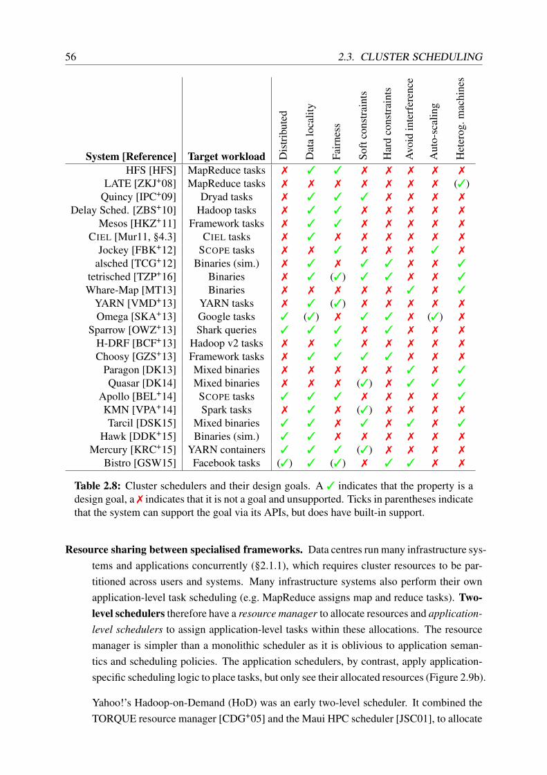
56 2.3. CLUSTER SCHEDULING
System [Reference] Target workload Dis
trib
uted
Dat
alo
calit
y
Fair
ness
Soft
cons
trai
nts
Har
dco
nstr
aint
s
Avo
idin
terf
eren
ce
Aut
o-sc
alin
g
Het
erog
.mac
hine
s
HFS [HFS] MapReduce tasks 7 3 3 7 7 7 7 7
LATE [ZKJ+08] MapReduce tasks 7 7 7 7 7 7 7 (3)Quincy [IPC+09] Dryad tasks 7 3 3 3 7 7 7 7
Delay Sched. [ZBS+10] Hadoop tasks 7 3 3 7 7 7 7 7
Mesos [HKZ+11] Framework tasks 7 3 3 7 7 7 7 7
CIEL [Mur11, §4.3] CIEL tasks 7 3 7 7 7 7 7 7
Jockey [FBK+12] SCOPE tasks 7 7 3 7 7 7 3 7
alsched [TCG+12] Binaries (sim.) 7 3 7 3 3 7 7 3
tetrisched [TZP+16] Binaries 7 3 (3) 3 3 7 7 3
Whare-Map [MT13] Binaries 7 7 7 7 7 3 7 3
YARN [VMD+13] YARN tasks 7 3 (3) 7 7 7 7 7
Omega [SKA+13] Google tasks 3 (3) 7 3 3 7 (3) 7
Sparrow [OWZ+13] Shark queries 3 3 3 7 3 7 7 7
H-DRF [BCF+13] Hadoop v2 tasks 7 7 3 7 7 7 7 7
Choosy [GZS+13] Framework tasks 7 3 3 3 3 7 7 7
Paragon [DK13] Mixed binaries 7 7 7 7 7 3 7 3
Quasar [DK14] Mixed binaries 7 7 7 (3) 7 3 3 3
Apollo [BEL+14] SCOPE tasks 3 3 3 7 7 7 7 3
KMN [VPA+14] Spark tasks 7 3 7 (3) 7 7 7 7
Tarcil [DSK15] Mixed binaries 3 3 7 3 7 3 7 3
Hawk [DDK+15] Binaries (sim.) 3 3 7 7 7 7 7 7
Mercury [KRC+15] YARN containers 3 3 3 (3) 7 7 7 7
Bistro [GSW15] Facebook tasks (3) 3 (3) 7 3 3 7 7
Table 2.8: Cluster schedulers and their design goals. A 3 indicates that the property is adesign goal, a 7 indicates that it is not a goal and unsupported. Ticks in parentheses indicatethat the system can support the goal via its APIs, but does have built-in support.
Resource sharing between specialised frameworks. Data centres run many infrastructure sys-tems and applications concurrently (§2.1.1), which requires cluster resources to be par-titioned across users and systems. Many infrastructure systems also perform their ownapplication-level task scheduling (e.g. MapReduce assigns map and reduce tasks). Two-level schedulers therefore have a resource manager to allocate resources and application-level schedulers to assign application-level tasks within these allocations. The resourcemanager is simpler than a monolithic scheduler as it is oblivious to application seman-tics and scheduling policies. The application schedulers, by contrast, apply application-specific scheduling logic to place tasks, but only see their allocated resources (Figure 2.9b).
Yahoo!’s Hadoop-on-Demand (HoD) was an early two-level scheduler. It combined theTORQUE resource manager [CDG+05] and the Maui HPC scheduler [JSC01], to allocate

CHAPTER 2. BACKGROUND 57
Scheduler
(a) Centralised,monolithic scheduler.
Resource manager
S0 S1 S2
(b) Two-levelpartitioned scheduler.
Cluster state
S0 S1 S2
(c) Shared-statescheduler.
S
S
S
S
S
S
(d) Fully distributedscheduler.
Figure 2.9: Comparison of different cluster scheduler architectures. Grey boxes representcluster machines, and coloured circles correspond to different applications’ tasks.
users’ clusters from a shared pool [VMD+13, §2.1]. Subsequently, Mesos [HKZ+11]and YARN [VMD+13, §2.2ff.] devised principled two-level architectures, multiplexingresources via offers (Mesos) or requests (YARN) resource multiplexing.
Engineering complexity. The diverse needs of cluster workloads make it challenging for largeorganisations to manage and evolve a single scheduler code base [SKA+13, §1].
Google’s Omega cluster manager thus introduced a partially distributed, shared state,distributed logic scheduler architecture. Omega supports multiple co-existent schedulerswithin the same cluster. The schedulers may be based on different implementations andrun distributedly [SKA+13, §3.4], each dealing with a fraction of the workload. However,unlike two-level schedulers, all schedulers contain weakly consistent replicas of the fullshared cluster state. They mutate the cluster state by issuing optimistically-concurrenttransactions against it (Figure 2.9c). Transactions may yield a successful task placement,or fail, necessitating a re-try. Microsoft’s Apollo takes this model a step further and onlydetects and resolves conflicts in worker-side queues on cluster machines [BEL+14].
Scalability to very short tasks. Some analytics workloads process interactive queries that mustreturn information in a matter of seconds. To facilitate this, work is broken down into alarge number of very short-lived tasks. Such small task granularities increase utilisationand combat straggler tasks’ effects on job completion time [OPR+13].
The short tasks only exist for sub-second durations, and thus the scheduling overhead– either from a centralised scheduler, or from transactions against shared state – can besignificant. The Sparrow fully distributed scheduler addresses this problem by entirelyeschewing shared state and coordination [OWZ+13]. Instead, cluster machines pull tasksdirectly from schedulers in response to probes (Figure 2.9d).
Different solutions are appropriate for different environments, and none of these architecturesis necessarily “better” than the others.

58 2.3. CLUSTER SCHEDULING
2.3.2 Data locality
Locality of reference is key to many engineering optimisations in computer systems, notablythe efficacy of caching mechanisms in microprocessors. Distributed systems also have notionsof “locality”: if an input to a task is not present on a machine, it must be fetched via the network,which necessarily incurs latency and increases network utilisation. To avoid this cost, clusterschedulers aim to increase the number of tasks that operate on local data.
Google’s MapReduce preferentially schedules map tasks on machines that have relevant GFSinput chunks available locally or across the same leaf switch [DG08, §3.4], and other systemsadopted similar optimisations [IBY+07; HKZ+11; MSS+11]. Research efforts further refinedthe concept: delay scheduling holds off starting tasks in the hope of task churn leading to betterlocations becoming available; Scarlett increases replication of popular input data to increasedisk locality [AAK+11]; and Quincy weighs the locality benefit of moving already-runningtasks against the cost of restarting them [IPC+09].
Early work optimised for disk locality, since reading data from a local disk was faster thantransferring it over the network. Data centre network bandwidth has increased, however, mak-ing differences between local and remote disks increasingly marginal [AGS+11]. Localityis still important, however: many data processing frameworks [ZCD+12] and storage sys-tems [ORS+11; LGZ+14] cache data in RAM, making the locality of in-memory objects animportant concern. Moreover, recent machine-learning workloads have locality constraints onGPUs [RYC+13; MAP+15; TZP+16], and require careful placement to ensure sufficient networkbandwidth between their tasks. Even disaggregated storage architectures based on NVMe flashdevices [KKT+16], which have no local data on each machine, require careful, workload-awareplacement in locations with sufficient CPU and network capacity [NSW+15].
Additionally, notions of locality exist within machines: remote memory access in NUMA sys-tems is costly, and locality of PCIe devices matters for high-performance network access. In-formation about such fine-grained locality inside a machine is normally only available only tothe local kernel CPU scheduler, not to the cluster scheduler.
2.3.3 Constraints
Not all resources are necessarily equally suitable for a particular application: availability ofspecial hardware features (such as flash-based storage, or a general-purpose GPU accelerator),software compatibility constraints (e.g. a specific kernel version), and co-location preferences(proximity to a crucial service, or distance from applications that negatively interfere) all con-tribute to the goodness of an assignment.
Scheduling is therefore sometimes subject to placement constraints. Such constraints are verycommon in practice: for example, 50% of Google’s Borg tasks have some form of simple

CHAPTER 2. BACKGROUND 59
placement constraint related to machine properties, and 13% of production workloads havecomplex constraints [SCH+11, §1].
There are three general types of constraints:
Soft constraints specify a “preferential” placement, indicating that a task benefits from thepresence of a certain property. For example, an I/O-intensive workload such as log crawl-ing might have a soft constraint for machines with a flash storage. The scheduler maychoose to ignore a soft constraint and proceed to schedule the task anyway.
Hard constraints by contrast, must be met by the scheduler. A task with a hard constraintcannot be scheduled until a placement that satisfies its requirements is found (or madeavailable vi preemption). In the flash storage example, this constraint would be appro-priate if the task cannot execute using a slower storage device – e.g. a fast, persistent logbacking a distributed transaction system. Likewise, an application that requires a specifichardware accelerator would use a hard constraint.
Complex constraints can be hard or soft in nature, but are difficult for the scheduler to dealwith. Combinatorial constraints, which depend not only on machine properties, but alsoon the other tasks running on the machine and on other concurrent placement decisions,are a prominent example of complex constraints. In the aforementioned flash storageexample, a combinatorial constraint might indicate that only one task using the flashdevice may run on the machine at a time.
Constraints reduce the number of possible placements available to a given task and thereforelead to increased scheduling delays [MHC+10; SCH+11; ZHB11].
Many schedulers support constraints, but there is little consensus on the types supported. Forexample, Sparrow and Choosy support only hard constraints and use them as filters on pos-sible assignments [GZS+13; OWZ+13]. Quincy, on the other hand, supports soft constraintsvia per-task placement preferences, but does not support hard constraints, as tasks have a wild-card “fallback” [IPC+09, §4.2]. Quasar supports soft high-level performance constraints, butrelies on the scheduler’s profiling and performance prediction mechanisms to satisfy them viacorrective action [DK14].
By contrast, YARN’s resource manager supports both soft and hard constraints [VMD+13,§3.2], and alsched [TCG+12] also supports both, in addition to complex combinatorial con-straints. However, tetrisched subsequently argued that support for soft constraints is sufficientand offers attractive benefits [TZP+16].
Support for constraints is a trade-off between high-level scheduling policy expressiveness,scheduler complexity, and job wait time. Different cluster schedulers make different choicesowing to differences in workloads and operating environments.

60 2.3. CLUSTER SCHEDULING
2.3.4 Fairness
Most warehouse-scale data centres are operated by a single authority, but nevertheless run awide range of workloads from different organisational units, teams, or external customers [SKA+13,§1]. These users may behave antagonistically in order to increase their share of the cluster re-sources. Consequently, cluster schedulers allocate shares and aim to provide fairness.
Some systems rely on task churn to converge towards users’ fair shares, resources are offeredto users according to their fair shares, but running tasks are not preempted if the allocationbecomes unfair. The Hadoop Fair Scheduler (HFS), which fairly shares a MapReduce clus-ter by splitting it into “job pools” [HFS], and Delay Scheduling [ZBS+10] are such churn-based approaches. The Sparrow distributed scheduler uses a similar approach: tasks experienceweighted fair queueing at each worker, and fair shares of the cluster emerge as tasks are servicedat different rates [OWZ+13, §4.2].
Quincy [IPC+09], by contrast, preempts running tasks to enforce fair shares. It models thescheduling problem as a flow network optimisation, and enforces the updated fair shares when-ever its solver runs. To guarantee progress, Quincy does not preempt tasks once they have beenrunning for a certain time; hence, temporary unfairness is still possible [IPC+09, §4.3].
Some policies support fair shares over multiple resource dimensions: for example, DominantResource Fairness (DRF) offers multi-dimensional max-min fairness by ensuring that eachuser receives at least her fair share in all dimensions [GZH+11]. DRF has proven propertiesthat incentivise users to share resources and to honestly state their demands [GZH+11, §3].DRF variants also exist for fair allocation with regard to placement constraints (ConstrainedMax-Min-Fairness (CMMF) in Choosy [GZS+13]) and hierarchical allocation delegation (inH-DRF [BCF+13]).
While strong fairness is appealing, it is unclear how useful it is in a single-authority data centre.Anecdotally, many production systems rely on out-of-bands mechanisms to ensure approxi-mately fair sharing [VPK+15, §2.5]. Furthermore, even though the scheduler may allocate fairresource shares, heterogeneity and interference (§2.1.2) can lead to significant differences inseemingly identical resource allocations.
2.3.5 Dynamic resource adjustment
Most cluster scheduling systems assume that all jobs’ tasks either have uniform resource re-quirements (as, e.g. with fixed-size MapReduce worker “slots”), or that users specify resourcerequirements at job submission time (e.g. in Borg [VPK+15, §2.3], YARN [VMD+13, §3.2] andMesos [HKZ+11, §1]).
Some cluster schedulers, however, support dynamic adjustment of resource allocations. This isbeneficial to harness spare resources, to satisfy job deadlines, or to cope with varying load.

CHAPTER 2. BACKGROUND 61
Omega’s MapReduce scheduler opportunistically allocates extra resources to increase the de-gree of parallelism when possible [SKA+13, §5]; Apollo likewise launches additional oppor-tunistic tasks within jobs if their allocations are not fully utilised [BEL+14, §3.5].
Jockey [FBK+12] dynamically increases the resource allocation of a SCOPE job if it runs a riskof missing its deadline, and decreases it if there is headroom. Similarly, Quasar [DK14] au-tomatically “right-sizes” resource allocations and chooses the best available resources, basedon co-location and machine types; it grows the resource allocation until the user-specified per-formance constraints are met. Finally, Borg’s “resource reclamation” mechanism dynamicallyreduces tasks’ resource requests to an envelope around their actual usage in order to reducereservation slack and improve utilisation [CCB+14; VPK+15, §5.5].
These examples highlight that resource allocations can be dynamically adjusted by the sched-uler. Most commonly, however, it is left to applications to introspect on their performance andrequest extra resources when necessary.
2.3.6 Summary
As I already discussed in Section 2.1.4, good scheduling decisions are essential to the efficientuse of cluster resources. This section has surveyed many existing cluster schedulers. I startedby looking at their architecture (§2.3.1), and then discussed several desirable features: supportfor locality within the cluster (§2.3.2), placement constraints (§2.3.3), fairness (§2.3.4), anddynamic resource adjustment (§2.3.5).
Few existing schedulers, however, address the machine heterogeneity and workload interferencechallenges highlighted earlier. Yet, in order to achieve deterministic workload performance athigh cluster utilisation, a cluster scheduler must:
1. integrate machine-level information and cluster-level information to make scheduling de-cisions based on fine-grained task profiling, machine type, and locality information;
2. avoid negative interference between workloads that share hardware resources by co-locating only those tasks that work well together; and
3. flexibly allow workload-specific scheduling policies to be expressed, so that the schedulercan be tailored towards the desired use case.
In Chapters 6–8, I will discuss Firmament, a new scheduler that supports these goals.

62 2.3. CLUSTER SCHEDULING

Chapter 3
A decentralised data centre OS model
In the previous chapters, I have highlighted the need for a more uniform, clean-slate foundationfor a data centre OS, replacing the ad-hoc abstractions built as part of distributed infrastructuresystems. I argued that such a replacement has the potential to make critical infrastructure moresecure and efficient.
In this chapter, I introduce a reference model for resource naming and management in a decen-tralised, data centre-scale operating system. This reference model informs the implementationof a prototype, DIOS, which I will discuss in Chapter 4.
I begin my description of the decentralised data centre OS model by defining key terms and con-cepts upon which the model relies (§3.1). Based on the challenges identified in Section 2.2.3, Ithen state efficiency goals and security requirements for the data centre OS model (§3.2).
I then describe the six key aspects of the decentralised data centre OS model:
1. The core abstractions of distributed objects, the building blocks which allow the modelto support the construction of diverse distributed applications (§3.3).
2. Resource naming, which uses globally unique, namespaced identifiers that act as capa-bilities for object discovery, and which can both be exposed to end-users and stored asserialised data (§3.4).
3. Runtime resource management and addressing, supported via translucent handles thatexpose context-dependent object meta-data and act as delegatable capabilities (§3.5).
4. How persistent storage of data is achieved in the model via a flat object store, whichflexibly supports different application-specific storage systems (§3.6).
5. Concurrent access to distributed objects, which the model supports via a transaction-likeI/O requests, which support different application-level concurrency models and consis-tency levels (§3.7).
Finally, I summarise the chapter (§3.8), before I move on to discuss my prototype implementa-tion of this model, DIOS, in the next chapter.
63

64 3.1. DEFINITIONS AND CONCEPTS
3.1 Definitions and concepts
Systems software research often relies on analogies between concepts to relate them to eachother, and to position new ones. For example, my survey of existing data centre infrastruc-ture systems that function as an “operating system” for the data centre (§2.2.2) relied on looseanalogies of these systems with classic OS functionality.
To specify my data centre OS model without ambiguity and contradiction, I need to be moreprecise. Hence, I assume the terms and definitions listed in the following.
Human users. There are three different categories of human users who directly or indirectlyinteract with the data centre OS:
1. An operator is a core systems developer or system administrator who has privilegedaccess to the cluster infrastructure, and who controls the admission and access controlpolicies applied by the data centre OS. The cluster manager developers are also operators.
2. An infrastructure user of the data centre OS is a developer who deploys applicationworkloads (§2.1.1.2) on the shared cluster infrastructure. Infrastructure users are subjectsof access control and security mechanisms.
3. Finally, an end user is a user of an application or web service that is backed by thedata centre application workloads. End users may store their data in the data centre,and interact with applications via their APIs, but they do not have direct access to theinfrastructure and cannot deploy their own applications.1
Systems software. The key pieces of operator-provided systems software that infrastructureusers interact with are:
• The data centre operating system (OS), which is the complete set of privileged code,system services, runtimes and libraries required to support infrastructure users’ applica-tions. Crucially, the OS contains all such software that is not ordinarily provided by aninfrastructure user, and which is ubiquitously available throughout the data centre.
• The trusted computing base (TCB) consists of those parts of the operating system thatare critical to maintaining its security, and whose compromise may jeopardise accesscontrol. The TCB consists of all machines’ local OS kernel and the cluster managementsoftware, but does not include other infrastructure services (e.g. a distributed storage sys-tem).
1While “cloud computing” may enable any end user to deploy applications in the data centre, they become aninfrastructure user when doing so.

CHAPTER 3. A DECENTRALISED DATA CENTRE OS MODEL 65
• The local OS kernel is the privileged code that runs on each machine to initialise, manageand perform privileged operations on its hardware. It can access any physical memory,and starts and terminates local programs. The kernel is part of the TCB, since compro-mising it allows bypassing access controls on (at least) local data.
• The cluster manager does not run inside the kernel, but is nevertheless part of the TCB,since it starts and stops application tasks within the cluster infrastructure, furnishes themwith inputs and outputs, and isolates them from other tasks. One or more instances ofthe cluster manager run within the data centre, deployed and configured by operators, andhandling infrastructure users’ requests to deploy applications.
Information hiding. When system designers conceive abstractions, they face a choice be-tween exposing and hiding information. Different approaches can be characterised as follows:
• An abstraction or operation is transparent if it is entirely invisible to the user, i.e. theinfrastructure user does not need to be aware of what is happening and the specifics ofhow it is implemented, and indeed has no way of finding out.
• By contrast, the opposite approach is opaque: an abstraction or operation is opaque if itdoes not hide any of the underlying details from the infrastructure user, or even requiresthem to be specified explicitly.
• A translucent approach takes the middle ground, hiding implementation details from theinfrastructure user by default, but allowing for introspection. In other words, translucentabstractions or operations may be treated as transparent or as opaque at the infrastructureuser’s choosing.
I define any other terms and concepts specific to my model when they are first introduced.
3.2 Requirements
My survey of existing data centre OS software revealed two challenges that are poorly addressedby existing systems (§2.2.3):
1. Efficient sharing of resources between tasks that are part of different jobs, distributedinfrastructure systems, and applications. I found that data are being copied unnecessarily,and that crucial information is often hidden even though systems share data.
2. Fine-grained protection and access control are lacking, and the existing mechanisms arecoarse, fragmented, and implemented as part of distributed infrastructure systems thateach invent their own, bespoke notion of protection. This makes it difficult to securelydelegate access to resources,

66 3.2. REQUIREMENTS
In the following, I concretise these challenges into a set of goals and requirements for thedecentralised data centre OS model.
3.2.1 Efficiency requirements
To make the decentralised data centre OS as efficient as possible, the model must meet twohigh-level goals:
1. It must supply uniform abstractions that applications can be built upon without having tounnecessarily transform data or resource representations.
2. It must expose sufficient information for efficient implementations of applications, andavoid mandating abstractions that can be costly.
In other words, we need an efficient and expressive, but yet minimal common denominator overmany applications, meeting three requirements.
1. The model and its abstractions must be scalable, so that the OS can run across manymachines and serve a large number of applications. For example, different replicas of aresource should be concurrently accessible without synchronisation.
2. Abstractions should be uniform across applications, and easy to comprehend. For exam-ple, since the location of a resource may not be known in advance, the abstractions foraccessing local and remote resources should be identical.
3. The abstractions should be introspectible, allowing applications to obtain information re-quired for efficient operation. For example, the abstraction for a remote resource shouldexpose the fact that it is remote, but access should not require implementing a wire pro-tocol.
Since both data centre machines and the network may fail, my model is decentralised: at thelevel of OS abstractions, it is a fully distributed architecture. The OS itself must not rely onsingular centralised state, and must allow replication of state, which aids scalability and faulttolerance. Specifically, all data stored in the system must be replicable, and no central authoritymust be required to maintain meta-data or permissions.
Note that this does not mean that all applications or infrastructure systems built atop the OSabstractions must be fully decentralised. Indeed, most infrastructure systems atop this modelwould likely still use a centralised controller; however, the OS abstractions should not them-selves require any centralised control or depend on a single point of failure.
Scalability of the data centre OS abstractions and interfaces can be derived from the scalableprinciples developed for single-machine operating systems on many-core architectures [BCC+08;
CHAPTER 3. A DECENTRALISED DATA CENTRE OS MODEL 67
BCM+10a; CKZ13]: like a scalable multi-threaded program, a scalable distributed system mustexploit asynchrony and coordination-free sharing, and avoid global atomic operations. OS ab-stractions should encourage commutative implementations where possible [CKZ+13].
More generally, since synchronisation in a distributed system is expensive, the model mustavoid implicit synchronisation, i.e. synchronisation that the infrastructure user is potentiallyunaware of. The data centre OS should inform applications of concurrent access, but shouldnot prevent it by default or itself enforce synchronisation or mutual exclusion. Infrastructuresystems and applications may, however, construct synchronised abstractions on top of the con-current access notifications exposed by the OS.
Distributed systems commonly use transparency to hide implementation details – consider,for example, the remote procedure call (RPC) concept [BN84], Mach’s transparent message-based object access via ports [SGG08, app. B.5], or the automated dependency tracking inDryad [IBY+07] and CIEL [MSS+11]. However, full transparency has the disadvantage ofpotentially unpredictable performance, since no introspection is possible. For example, everyoperation in distributed shared memory systems (e.g. Mungi [Hei98]) and transparent message-passing distributed object systems (e.g. Mach [ABB+86] and MIKE [CNT+93]) may requirecommunication with a remote machine and see high latency, but the application cannot detectin advance whether it will.
Translucency serves to offer the simplicity of transparency without restricting applications’freedom to introspect: it makes abstractions transparent by default, but opaque on request.This obviates the need to understand the detailed low-level operation of a distributed system,without making it impossible to introspect the details.2 The OS abstractions in my model shouldtherefore be translucent, but also carry contextual meta-data that expose detailed informationabout resources for introspection. The application may choose to ignore this information (andforgo predictable performance) or may use it to optimise (e.g. choose a more proximate replica).
3.2.2 Security requirements
As noted in Section 2.2.3, the security of current distributed infrastructure systems leaves muchto be desired: it is fragmented, enforced selectively, and often insufficiently fine-grained.
My decentralised data centre OS model aims to improve upon this. In the following, I reviewthe threat models considered, and the security principals that the model must support.
Goals. A data centre operating system must ensure that workloads belonging to different jobs,users, or even commercial entities, can safely share the cluster infrastructure. To achieve this, itmust ensure three properties:
1. Isolation between different infrastructure users and different tasks, and their data andresources, unless explicitly shared.
2The term “translucency”, meaning “transparency with exposed meta-data”, also sees occasional use in pro-gramming language literature, e.g. by Rozas [Roz93].
68 3.2. REQUIREMENTS
2. Deniability of the existence of resources inaccessible to a task or infrastructure user.
3. Auditability of any sharing or communication of data or resources, and of access to them.
Unlike in a traditional OS, isolation and sharing must also extend across machines.
For example, the existence of a specific end-user email may only be visible to serving andanalytics jobs that are authorised to use it. However, a task in an analytics job might need todelegate work to helper tasks (e.g. a decompression routine, or a virus scanner) without leakingsensitive data outside the trusted job, and the fact that it does should be recorded in an audit log.
3.2.2.1 Definitions
The security principals and resources in my model are defined as follows:
• Subjects (principals) are infrastructure users, or non-human service accounts.
• Objects (resources) are items of volatile or persistent data, hardware resources, tasks, andother OS-level abstractions (e.g. IPC endpoints, timers).
As I already noted in Section 3.1, the trusted computing base (TCB) – which may access anyobject, and which furnishes subjects with their rights – contains the local machine kernels andthe cluster manager. Additionally, the identifier resolution mechanism, which I discuss in Sec-tion 3.4, is also part of the TCB.
3.2.2.2 Threat model
My model aims to defend the data centre infrastructure and its users against threats that arisefor two reasons: deliberate malice and accidental mistakes. More specifically, there are fourthreats that my model seeks to address:
Internal malice occurs when an evil, or subverted, principal attempts to gain access to a re-source that ought not to be available to it. For example, a malicious infrastructure usermay run a specially crafted MapReduce job that leaks its inputs to a third party. Mymodel’s goal is to compartmentalise resources to restrict infrastructure users’ access toonly those resources that their jobs need and legitimately access, minimising exposure.This requires more fine-grained access control than current systems provide.
External compromise happens when an external party obtains unauthorised access, typicallyby exploiting and impersonating an existing principal. If subverting a valid principal, thisthreat becomes identical to internal malice. For example, a malicious end-user mightexploit a vulnerability in a decompression routine to gain access to the infrastructure andsubvert the identity of the invoking task. My model’s goal is to make such compromise

CHAPTER 3. A DECENTRALISED DATA CENTRE OS MODEL 69
less likely by restricting the abstractions accessible to distributed applications, and tocontain the compromise as much as possible if it does happen.
Accidental exposure of private resources can occur without malice, due to bugs or incorrectlyconfigured permissions. For example, the permissions of end-user data in a distributedfile system might be insufficiently restrictive, allowing a buggy analytics job to acciden-tally expose more data than intended. My model’s goal is to reduce the exposure in thissituation by restricting tasks’ access to the minimal resources required.
Hardware failures typically occur without malicious intent, but lead to sudden unavailabilityof resources that may have security or liveness implications. For example, a networkpartition can make an authentication server temporarily unreachable. My model’s goal isto support access control that remains secure and available even under failures, as long asthe target resource remains available.
However, several types of threats are out of the scope of my work, and must be mitigated usingother mechanisms:
Compromise of the TCB may occur if an evil subject or an external attacker successfully ex-ploits a vulnerability in the OS kernel, the name service, or in the cluster manager. En-crypted memory enclaves might help reduce application exposure to such attacks [BPH14;CD16].
Hardware and physical access exploits can circumvent access control and potentially exposeprivate information. It is difficult for an OS to defend against such threats in the absenceof end-to-end encryption and hardware support for oblivious computation [MLS+13;LHM+15].
Information Flow Control (IFC) involves the enforcement of policies on whether informa-tion can be transferred between different subjects, including indirectly. While my modelrestricts accidental exposure of information, and reduces the attack surface via fine-grained access control, IFC techniques such as taint tracking (e.g. in HiStar [ZBK+06]and DStar [ZBM08]) are required to enforce such policies.
3.2.3 Other requirements
There are several additional requirements the decentralised data centre OS model must meet,but which are not directly related to efficiency or security.
Distributed applications are complex, and many policy decisions are application-specific. Adata centre operating system must thus balance specifying mechanism against maintaining theflexibility to support externalised policies specified by applications. To achieve this, sufficientinformation must be exposed to applications to enact common distributed systems policies –
70 3.3. DISTRIBUTED OBJECTS
such as where to locate data, or whether to maintain strongly consistent replicas – of theirchoice.
Incremental adoption. Even though a new data centre OS model has many benefits, portingsoftware to it will be time-consuming. Hence, an incremental adoption must be feasible, withincreasingly larger portions of data centre workloads using the new paradigms, while legacyapplications continue to work. While not all of the benefits of the model might initially beattainable, incremental migration should increase efficiency and security.
Next, I explain how a distributed object abstraction helps my model meet these and the previ-ously outlined requirements.
3.3 Distributed objects
Objects are a convenient abstraction commonly used both for programming and structured datastorage. Their lowest common denominator definition is perhaps that an object is a collectionof related, structured state. Objects are created and destroyed atomically, and often have uniqueidentifiers.
An object abstraction has several advantages for distributed systems:
1. Objects impose structure on otherwise unstructured data and delineate scopes for updateconsistency. For example, Amazon’s Dynamo key-value store holds versioned objectsthat can diverge [DHJ+07, §4.4], while Google’s BigTable store guarantees consistentupdates within a row object, but not across row objects [CDG+06, §2].
2. Object-level replication enables fault tolerance: an object encapsulates all state requiredto act as an independent, replicated entity. For example, distributed key-value stores suchas Cassandra [LM10, §5.2] replicate keys and their corresponding objects across faultdomains to achieve reliability. Data processing systems’ object abstractions – e.g. Spark’sresilient distributed datasets (RDDs) [ZCD+12] and CIEL’s data objects [MSS+11] – offerfault tolerance based on replication and deterministic replay.
3. Objects simplify distributed programming, as they lend themselves to a communicat-ing actor model in which actors maintain private state and exchange messages to ef-fect state changes. For instance, Sapphire can concisely express complex distributedsystems via transparently interacting objects in combination with modular “deploymentmanagers” [ZSA+14, §8.1].
4. Dependencies between objects enable data-flow computation models that lend themselvesto automatic parallelisation. For example, Dryad [IBY+07] and Naiad [MMI+13] arebased on data-flow of records between stateful vertices, while CIEL schedules dynami-cally generated tasks based on their dependencies on input objects [MSS+11, §3.1].

CHAPTER 3. A DECENTRALISED DATA CENTRE OS MODEL 71
M0 M1 M2T0 T1
T2 T3
o0
o3
o1o2
o4 o5
kernel objs kernel objs kernel objs
cluster manager
Figure 3.1: Schematic overview of the decentralised data centre OS model. Three taskobjects, T0–T2, are shown as circles; four physical blob objects are represented as docu-ments; and two streaming communication objects as pipes. The shaded parts of the systemare part of the TCB. Solid arrows indicate data flow, dotted arrows object creation, anddashed arrows a persistent reference.
These, combined with the requirements of a fully distributed architecture and support for ex-tensible application-level policies, make a distributed object model a good fit for a data centreoperating system.
My model is centred around two separate object notions:
• A logical object is named by a single, globally unique identifier, but can have manyreplicated instances that are interchangeable for application purposes.
• A physical object, by contrast, is a single, specific object instance with clearly definedlocation, and a target on which applications can perform operations or I/O. Each physicalobject is part of exactly one logical object.
Otherwise, the distributed object model is based on a deliberately broad definition and onlyassumes that:
(i) each logical object has a globally unique identifier;(ii) a logical object’s replicated instances (≡ corresponding physical objects) may be used
interchangeably and carry the same globally unique identifier;(iii) each logical object has a type, which is either a passive blob (a sequence of bytes), a
streaming communication endpoint (a FIFO channel), a task (a process), or a group (anamespace), and its physical object instances are entities of said type;
(iv) a physical object is created and deleted, but not necessarily updated, atomically;(v) physical object handles expose meta-data that applications can inspect to make policy
decisions.

72 3.3. DISTRIBUTED OBJECTS
i0 i1 i2 i3 i4
M0 M1 M2 M3 M4
m0,2m0,1m0,0m1,2m1,1m1,0
m2,2m2,1m2,0m3,2m3,1m3,0
m4,2m4,1m4,0
R0 R1 R2
o0 o1 o2
Figure 3.2: Distributed MapReduce (five map tasks, three reduce tasks): a deterministicdata-flow batch computation. In this example, five logical input objects (“splits”), i0–i4,are transformed into three logical output objects, o0–o2, via physical intermediate objectsmi,o. The intermediate and output objects are created by a MapReduce controller task (notshown), which also spawns the tasks via the cluster manager.
Specifically, my model – unlike the object notions of many classic distributed OSes (§2.2.1) –does not:
(i) assume any (specific) language-level integration of its object notion;(ii) impose any requirements on the structure of physical objects, e.g. storing references to
other logical or physical objects in a particular way, or coupling code and data;(iii) enforce a specific consistency level for physical objects (≡ replicas); or(iv) guarantee the continued availability of a live physical object in the presence of failures.
This object notion is practical for a data centre OS as it makes minimal assumptions about theapplication implementations.
Figure 3.1 illustrates the object concept with an example of four task objects (T0–T3) that accessprivate and shared blobs (o0–o3) and communicate via unidirectional channels (o4–o5). In thefollowing, I show how two typical data centre applications are expressed in my object model.
Examples. Consider (i) a distributed MapReduce [DG08] implementation, which representsa typical deterministic data-flow application, and (ii) an event-driven HTTP server with an in-memory key-value store back-end, which is typical of an end-user-facing service application.
In the MapReduce framework (Figure 3.2), the ith map task (Mi) applies a map function of theform map(key, value)→ 〈key2, value2〉 to all records in its input object (ii). All maptasks run in parallel. The items in each resulting list are subsequently hash-partitioned on key2and the resulting intermediate sets of key-value pairs (stored in intermediate physical objectmi, j) are provided as input to the parallel reduce tasks (R j taking mk, j for all k). These apply

CHAPTER 3. A DECENTRALISED DATA CENTRE OS MODEL 73
acc.
cs0
cs1
cs2
W0
W1
W2
d0
d1
d2
bs0
bs1
bs2
B0
B1
B2
bd0
bd1
bd2
Figure 3.3: Multi-process HTTP server with back-end: the user-facing service is imple-mented with three front-end worker tasks (W0–W2) that share a physical acceptor object(acc.) which supplies physical client connection objects (cs0–cs1). These serve responsescomposed from static data (di) and dynamic data, bdi (e.g. from a key-value store), obtainedby communicating with three back-end tasks (B0–B2) via physical stream objects (bs0–bs1).
a reduce function, reduce(key2, values)→ out-values, storing the final values inan output object o j. A controller task manages the map and reduce tasks and monitors them forfault tolerance, re-executing any failed tasks.
The HTTP server (Figure 3.3), by contrast, is a non-deterministic, event-driven application.The design is similar to the event-driven “reactor pattern” in the widely-used nginx web server:multiple worker tasks (Wi) all poll a TCP acceptor object (acc) to accept client connections.The client connections are materialised as TCP stream objects (cs j), which the handling workerprocess performs I/O on. In the back-end, the worker processes may interface with either staticcontent in the form of blob objects (in memory or on disk) or dynamic content from a key-valuestore via references to stream objects (bsi) that communicate with the back-end tasks (Bi) overshared memory or the network. Fault tolerance can be implemented by the cluster managerrestarting any failed worker tasks.
3.4 Resource naming
Each resource in the decentralised data centre OS model is represented by a logical object.This logical object must be named, and my model consequently assigns it a globally uniqueidentifier. Unique identifiers are required for two reasons:
1. The operating system itself must be have a way of unambiguously referring to a particularlogical object.

74 3.4. RESOURCE NAMING
2. Applications must have identifiers for logical objects in order to bootstrap their access tothem, and to record and communicate their existence.
In keeping with the definition of my model’s logical object notion in the previous section, theidentifier refers to all physical objects for a logical object, which must be interchangeable (i.e.usable with equivalent semantics) from the application’s perspective.
For example, consider a strongly consistent distributed key-value store that requires replicationof writes for fault tolerance: its tasks store a value by writing it to multiple physical objects,which in combination form a logical object representing the stored value. To fit the decen-tralised, distributed data centre OS model’s object semantics, the key-value store must maintainthe physical objects’ interchangeability after serving a write. To achieve this, it must eitherensure that all physical objects are updated atomically (via application-level locking or trans-actions), or that the updated value is stored in a new logical object (with a new identifier), andthat the mapping in the key-value store is atomically updated to refer to the new logical object.
It is worth noting that physical objects also have unique identifiers, but these are ephemeral:as I explain in Section 3.5, they are only locally valid within a task context, cannot be storedpersistently, and are only partially exposed to applications.
Properties. Logical object identifiers, however, are exposed to applications and can be arbi-trarily stored and communicated. Hence, they must have three key properties:
1. In order to be suitable for persistent storage and for communication over the network asplain (binary or text) data, the identifiers must be serialisable.
2. To make them usable anywhere in the data centre, and to decouple them from physicalobjects, identifiers are location-independent and do not encode the physical location of aresource (unlike, e.g. a hostname:port combination).
3. To restrict the impact of leakage, translation of identifiers into physical objects must belimited. Hence, logical object identifiers are namespaced: they only form a data centreOS capability for resource identification within a namespace, even though applicationsmanage provenance.
Generation. To meet the requirement of a fully distributed architecture, identifiers need to begenerated from local information only. Moreover, for security purposes, they must be unforge-able and unguessable. In many cases, simply picking uniformly random identifiers from a largespace is sufficient to meet these needs, and also yields an unambiguous identifier that can bestored as data. This is a good match for the semantics of many existing data centre applications:for example, unforgeable identifiers are already used in URLs referring to photos and othercontent objects in many web applications.

CHAPTER 3. A DECENTRALISED DATA CENTRE OS MODEL 75
However, many data centre applications – especially those used for parallel data processing– express deterministic computations. They leverage the determinism to, for example, sim-plify the programming model and support replay-based fault tolerance (e.g. in MapReduce,CIEL [MSS+11], and Spark [ZCD+12]). Determinism is also useful to schedule computationswith data dependencies and enables memoisation optimisations (as in CIEL [Mur11, §4.2.1]and Tachyon [LGZ+14, §3.2]). The data centre OS model therefore also supports deterministicgeneration of identifiers using a hash function that combines the chain of previous identifiers togenerate new ones.
Resolution. Logical object identifiers exist in order to be translated into sets of interchange-able physical objects that applications can work with. This translation from a location-independentidentifier to physical objects that translucently expose location information is called resolution,and is the responsibility of a name service that forms part of the data centre OS model.
This name service can be implemented by the OS itself, or may itself be delegated to an infras-tructure application, but either way forms part of the data centre OS TCB. This comes becausethe name service knows about all logical and physical objects, and about the mappings betweenthem. This makes it critical to the security goals of resource isolation, deniability of resourceexistence, and auditability of resource access (see §2.2.3.2 and §3.2.2).
Resource identifiers, when presented to the name service, form capabilities for name resolution:the knowledge of a logical object identifier (i.e. being able to name a resource) authorises thepresenting task to obtain the corresponding set of physical objects. Importantly, such global,coarse-grained “identifier capabilities” can be treated as data (i.e. stored and communicated)due to their cryptographic generation: possession of the bit pattern is sufficient to authoriseidentifier resolution via the name service, independent of how the bit pattern was obtained. Anidentifier capability is atomic, i.e. it cannot be subdivided or refined (e.g. into a capability onlyto a subset of physical objects).
However, as presented thus far, identifier capabilities have a dangerous security flaw: leakingan identifier’s bit pattern enables an attacker to obtain access to the physical objects. To preventthis attack, identifiers are part of one or more namespaces, and are only resolvable within these.The combination of namespaces and identifiers is a form of split capability [KRB+03]: giventhe identifier and access to a namespace that maps it, the holder can discover the correspondingphysical objects. Either part on its own, however, is useless.
This restriction grants access only to tasks which have access to an appropriate namespace.Namespaces are themselves represented as objects: they can be created, have identifiers, andcan be shared between tasks (albeit subject to some restrictions).
However, even identifiers and namespaces on their own are insufficient to fully implementcapability-based protection in the decentralised, distributed data centre OS model. This is for

76 3.4. RESOURCE NAMING
System Capability storelocation
Secured by
Cap
abili
ties
asda
ta
Loc
atio
ntr
ansp
aren
t
Refi
nem
ent
poss
ible
Eden [LLA+81] user-space + kernel MMU 7† 3 3
Accent [RR81] user-space + kernel MMU 3 3 7
Mach [ABB+86] user-space + kernel MMU 3 3 7
Amoeba [MRT+90] user-space cryptography 3 3 3
Plan 9 [CGP+02]‡ kernel cryptography 7 7 7
Barrelfish [BBD+09] kernel (monitor) MMU 7 7 3
Web URLs user-space cryptography 3 3 7
Macaroons [BPE+14] user-space cryptography 3 3 3
Identifiers (§3.4) application (user-space) cryptography 3 3 7
Handles (§3.5) user-space + kernel MMU + crypto. 7 7 3
† Capabilities in Eden have corresponding kernel meta-data, so they cannot be treated as ordinary data.‡ Plan 9 uses capabilities only locally to empower its factotum server to authenticate changes of user ID.
Table 3.1: Previous systems’ distributed capability schemes compared to the decentraliseddata centre OS model.
two reasons: first, identifiers are atomic and do not express fine-grained permissions (e.g. read-/write access); and second, they do not carry sufficient information to form a translucent ab-straction (as required for efficiency, cf. §3.2.1). Indeed, it is not possible for a single capabilityto be application-managed, storeable, communicable, delegatable, and translucent, since theseproperties are in some cases mutually exclusive (e.g. arbitrary persistent storage and translu-cency). Instead, my model supports another type of capability used as a context-specific handlefor resource management, which I describe in the following section.
Related approaches. Several previous distributed systems made use of identifiers as capabil-ities (see Table 3.1).
In Eden, capabilities identified “Ejects” [LLA+81], which were distributed objects. Eden’s ca-pabilities were location-independent, but could not be treated as data, since – being originallydesigned to rely on hardware support via “Access Descriptors” in the Intel iAPX 432 [Lev84,§9.3.2] – they were implemented as two-part segregated capabilities, with the Eden kernel hold-ing private meta-data required for their use [ABL+85, p. 50].
The Amoeba distributed operating system used sparse cryptographic capabilities that weremanaged entirely by user-space server processes [TMV86]. Consequently, capabilities couldbe treated as data and exchanged over the network. Amoeba capabilities were also location-independent and could be refined. However, Amoeba relied on unforgeable hardware sourceaddresses being network messages for security.

CHAPTER 3. A DECENTRALISED DATA CENTRE OS MODEL 77
Many modern web applications use cryptographically derived URLs as capabilities.3 Sharingsuch a URL amounts to delegating (copying) the capability, although the capability cannot berefined further by recipients. Likewise, web cookies and Macaroons [BPE+14] are effectivelydistributed capabilities. All of these capabilities are location-independent, and can be storedand communicated as raw data.
3.5 Resource management
In addition to identifiers for logical objects, the model also requires an abstraction that imple-ments a secure handle to a physical object. This handle must uniquely identify a physical object,carry sufficient information for the holding task to interact with the object (irrespective of itslocation), and allow introspection via translucent meta-data for efficiency.
Handles are the targets for resource management operations (e.g. sharing, deletion) and I/Oon physical objects’ data. Unlike identifiers, they carry permissions and other meta-data (e.g.a location, a persistency level, etc.). The values of some of the meta-data, such as locality,depend on the observer. Thus, a handle is owned by a specific task and its meta-data specific tothe owner task and the context of the physical object.
Consequently, handles are ephemeral and only persist as long as their owner task: they cannotbe stored persistently. For initially unreferenced physical objects (e.g. on persistent storage),this means that handles must be created by resolving their identifiers, as only these can bestored as data.
To ensure that handles can only be generated by identifier resolution, they must guarantee un-forgeability; i.e. it must not be possible for an application to gain access to a physical objectby means of synthesising a fake handle. Handles therefore form local, context-sensitive handlecapabilities, which cannot be treated as data, and which are a type of segregated capabilitybetween the TCB and the application. Each handle has a public part that is exposed to theapplication, and a TCB-private counterpart that is accessible only to the local OS kernel.
Delegation. The data centre OS must sometimes be able to generate restricted versions of acapability, e.g. removing permissions. Unlike identifiers, handle capabilities can be refined bythe TCB. This is useful, for example, when a helper task needs restricted access to only a subsetof the permissions available to the parent task. Such refinement4 of capabilities is achieved bythe model supporting delegation of handles.
Delegation involves creating a new, possibly more restricted, copy of a handle via the TCB. Thenew handle may be owned by the same task, or by a different task, as the original handle. It
3Consider, for example, the “share via link” functionality in Google Docs (http://docs.google.com)or Doodle (http://doodle.com).
4Sometimes also called “reification” or “minting” in capability literature.

78 3.5. RESOURCE MANAGEMENT
is the TCB’s responsibility to adapt the handle to the target context, to create the new handle’skernel and application parts, and to notify the target context of the delegation.
When handle capabilities are delegated across machines, they must be sent over the data centreinterconnect. This requires unforgeability of delegated capabilities across machines, which isnon-trivial to attain in a distributed system:
• Man-in-the-middle attacks can occur when capabilities are intercepted on the sharedinterconnect: for example, a compromised switch might further delegate a copy of anobserved capability to a colluding host by impersonating the delegation protocol.
• Replay attacks involve the recording and later re-use of a capability, but can be defendedagainst by ensuring the freshness of delegated handle capabilities.
Authentication protocols such as Kerberos [SNS88] or the Needham-Schroeder-Lowe authen-tication protocol [Low95] solve this problem by authenticating the communicating parties, butrequire a logically centralised authentication server to maintain shared secrets (Kerberos) orkeys (Needham-Schroeder-Lowe). Such centralisation would violate the principle of full distri-bution in the decentralised data centre OS.
Since data centres are operated by a single authority, some attacks – such as compromises ofswitch firmware – although possible, are rather unlikely. In addition, most data centre operatorsencrypt even internal data centre traffic [EFF13], which helps defend against snooping. Forthe purpose of my model, I consider such threats to be out of scope and assume an uncompro-mised TCB and interconnect. The secure delegation of capabilities across untrusted commodityinterconnects is, however, an interesting area for future work (see §9.1.3).
Resource management summary. Together, identifier and handle capabilities enforce manda-tory access control. An identifier capability must be resolved to one or more local, context-sensitive handle capabilities before an application can interact with a logical object. Whileidentifier capabilities refer to logical objects, handle capabilities help manage physical objectsand effect I/O on them. However, handle capabilities are only valid within their task context,while identifier capabilities are valid within any task that has access to their namespace.
This split also controls capabilities’ provenance: in my model, the resolution of identifier ca-pabilities respects namespaces, which restricts the set of tasks that can use them, but does notrestrict their communication. Handle capabilities, by contrast, can only be transferred to othertasks via delegation through the TCB, but can be refined, and can be delegated to any task thatthe owner task can name.
Related approaches. As with identifier capabilities, my notion of handle capabilities is sim-ilar to capability concepts in several prior systems (Table 3.1).

CHAPTER 3. A DECENTRALISED DATA CENTRE OS MODEL 79
Traditional capability schemes typically relied on machine hardware to protect their capabilities.For example, the CAP Computer [WN79], the iAPX 432 [Lev84, §9.3.2], and CHERI [WWC+14]use custom hardware or hardware extensions. By contrast, Mach [ABB+86], EROS [SSF99],seL4 [KEH+09], and Barrelfish [BBD+09] rely on memory protection hardware to separatecapability space and data space.
Accent [RR81] and Mach [ABB+86] used capabilities to control access to “ports” (IPC end-points), between which message-based IPC could communicate capabilities. Capabilities grantedaccess to ports and were location-independent, but could not be refined. In Mach, the sendingof port capabilities in messages had “move” semantics: the sender lost access to the port whendelegating the capability [SGG08, app. B.5].
The Barrelfish OS uses a distributed capability scheme based on the segregated seL4 capabili-ties [SEL4RM, §2.2, §2.5], which hierarchically refines capabilities [Nev12, pp. 29–30]. Whencapabilities are shared, they must be serialised and sent via a secure channel [BFTN0, p. 10].Since Barrelfish does not have a transparent object abstraction, capabilities are not location-independent.
3.6 Persistent storage
Data centre storage systems are often more reminiscent of the flat data stores in early operatingsystems than of today’s complex hierarchical file systems such as ext4, NTFS, or NFS.
Storage systems such as BigTable [CDG+06] and Dynamo [DHJ+07] are flat key-value storesrepresenting a distributed map, while others, like FDS [NEF+12], Haystack [BKL+10] andf4 [MLR+14], are distributed blob stores. While hierarchical distributed file systems exist (e.g.GFS [GGL03], HDFS [SKR+10], and TidyFS [FHI+11]), they have far more restricted seman-tics than “legacy” file systems. For example, HDFS only supports appending writes on existingfiles, rather than random write access [SKR+10, §3.A]. If needed, directory services are imple-mented via a meta-data controller, while the actual data are stored as flat blocks (e.g. 64 MBchunks in GFS and HDFS, 8 MB “tracts” in FDS).
The decentralised data centre OS model therefore has the opportunity to simplify the storagesubsystem. Simplifying the storage stack can make it less error-prone and easier to scale, andmay also improve I/O performance if the abstractions are a better match for data centre storage.
The storage interface for the decentralised, distributed data centre OS model is therefore a min-imal one: uniquely identified objects are stored in a flat persistent object store. This approachexternalises the implementation of hierarchical (or other) storage abstractions to higher-leveldistributed applications, rather than layering them atop an already-hierarchical baseline storageabstraction. For example, both BigTable-style distributed maps and a GFS-style distributed filesystem can be implemented on top of a simple object store. Protection and access control across

80 3.7. CONCURRENT ACCESS
both of these higher-level abstractions can then rely on the uniform capability abstractions pro-vided by the data centre OS (§3.4–3.5).
This storage abstraction also allows common optimisations such as caching to be easily ex-pressed. Logical objects in the store may be replicated using multiple physical objects, andthe replicas (≡ physical objects) may have different persistence levels. For example, somephysical objects may be cached copies in volatile memory, while others are on durable storage,and finally, some might be memory-mapped with a persistent backing copy. The translucentmeta-data of the physical objects’ respective handle capabilities exposes the information as towhether a physical object is in the durable store or not.
Related approaches. A flat object store model is similar to the Multics segment model, anearly OS storage abstraction. In Multics, segments were named blocks of memory which couldbe backed by persistent storage or another device [VCG65, pp. 207–8]. Multics transparentlyabstracted the segments’ actual storage location and moved segments automatically and trans-parently between different locations [DN65]. By contrast, “translucent” handle capabilitiesallow introspecting the storage location of physical objects in my model.
Many later single address space OSes, such as Grasshopper [DBF+94], Opal [CLF+94], andMungi [Hei98], also supported persistent segments or objects. In Opal, objects are also held ina pervasive, flat store [CLF+94, §4.4]. More recently, distributed data processing systems suchas CIEL [Mur11, §4.5], and high-performance network attached storage (NAS) systems haveadopted similar object-centric storage models [CWM+14, §4].
3.7 Concurrent access
Many data centre applications are I/O-intensive and concurrent: they communicate with otherapplications, process large amounts of streaming data from the network, or process static datafrom durable storage in parallel using many tasks. Oftentimes, different applications are com-bined, and may share data with each other.
The data centre OS model therefore needs to provide a way for workloads to access remotephysical objects, and a way to share physical objects between tasks. Depending on the physicalobject and the applications’ consistency requirements, certain concurrent accesses might beacceptable. Since application-level consistency guarantees vary substantially across differentsystems, my model must not dictate a specific concurrent access semantic, however, but insteadallows applications to define their own policies.
The decentralised, distributed data centre OS model therefore uses transaction-like I/O re-quests, which are a flexible and low-overhead way of tracking concurrent access and notifyingapplications when it occurs. An I/O request delineates the time between the acquisition of I/Oresources (i.e. a buffer for reading or writing) and the completion of the intended operation (viz.

CHAPTER 3. A DECENTRALISED DATA CENTRE OS MODEL 81
T o
ACQ_READ(mode)
SUCC(data) / FAIL
COMM_READ
SUCC / FAIL
(a) Read request.
T o
ACQ_WRITE(mode)
SUCC(data†) / FAIL
COMM_WRITE(data)
SUCC / FAIL
(† optional, only some object types.)
(b) Write request.
Figure 3.4: Sequence diagrams of (a) read and (b) write requests: the caller first acquires(ACQ), then commits (COMM). The arrows are calls from the task (T) to the local kernel onthe machine maintaining the physical object o, and their returns.
reading and processing data, or writing them to the buffer). An I/O request is either a readrequest or a write request.
An I/O request begins by acquiring a request: the application specifies the desired operationand concurrent access semantics for the target physical object. If successful, the request is inthe acquired stage, during which the application performs I/O. Once the application finalises itsI/O, it commits the request and asks the OS to validate whether the concurrent access semanticsdid indeed hold for its duration. If successful, the request is committed; otherwise, it is aborted.
I/O requests are similar to optimistically concurrent transactions (as e.g. in Farm [DNN+15]).However, I/O requests do not offer transactional semantics (e.g. ACID and guaranteed rollback).Each I/O request is also specific to an individual physical object, i.e. it cannot offer multi-objectconsistency semantics, which must be implemented by the application.
Figure 3.4 illustrates how I/O requests proceed, and how the flow of data and control differsbetween read and write requests.
Read requests receive their data in the acquire stage, or fail to acquire if the requested con-current access semantics cannot be satisfied by the physical object in its current state(e.g. because other tasks already have outstanding I/O requests on it). The validity of thedata read is checked at the commit stage, which may fail if the desired concurrent accesssemantics were violated during the request.
Write requests receive a working buffer on acquire. Depending on the type of the target phys-ical object, this buffer may or may not already contain existing object data. The task thenwrites to the buffer, and the commit stage indicates if the concurrent access semanticsheld during the request.

82 3.8. SUMMARY
For write requests, the effect of a failed commit depends on whether the physical object exposesraw buffers (e.g. with a raw shared memory object), shadow copies (e.g. a double-bufferedshared memory object), or appends writes sequentially (as with streams). With sequentiallyapplied writes or shadow copies, the changes are easily discarded. In the case of an exposedraw buffer, however, changes have already been applied at the commit point. In this case,the data may potentially have been corrupted by the invalid request, and the OS must eitherinvalidate the physical object for all tasks that access it, or the application must implement itsown recovery procedure.
I/O requests are optimistically concurrent: in other words, the assumption is that they eventuallysucceed after potential back-offs and re-tries. There are no implicit OS-level per-request locksthat can enforce progress, because they would require costly and unscalable distributed lockingprotocols. However, the acquire and commit points of I/O requests offer “hooks” for construct-ing application-specific and multi-object mechanisms. For example, a distributed mutex lockcan be built atop I/O requests by having them race to acquire a shared object for exclusiveaccess, setting the value to “locked” on success.
Related approaches. Mechanisms akin to I/O requests exist in prior distributed systems,although they typically have stronger transactional semantics. For example, the Locus dis-tributed OS had network transparency [WPE+83], and supported nested transactions on repli-cated files [MMP83].
The Clouds OS supported “atomic actions” with transactional semantics based on per-threadand per-object consistency levels [DLA88, §5]. The notion of threads that go through phases ofdifferent consistency semantics is similar to the I/O request notion I have described, but – unlikeI/O requests – assumes a particular threading model and object-level consistency labels [CD89].
Distributed shared memory (DSM) systems often had similar semantics. For example, Muninwas based on release consistency (allowing temporary inconsistency of objects) and, like I/Orequests, could express multiple consistency levels [CBZ91]. My I/O request system could befurther extended with flags similar to those employed by Munin.
Finally, Software Transactional Memory (STM) [ST97] enforces transactional semantics formemory accesses, typically with the goal of simplifying concurrent programming. I/O requestsare more coarse-grained than STM and do not have transactional semantics, but operate overin-memory and durable objects alike.
3.8 Summary
This chapter introduced the decentralised, distributed data centre OS model, a clean-slate refer-ence model for uniform, efficient, and secure data centre resource naming and management.

CHAPTER 3. A DECENTRALISED DATA CENTRE OS MODEL 83
After defining key terms and concepts (§3.1), I distilled the shortcomings of current infrastruc-ture systems observed in Section 2.2.3 into a set of requirements for my model (§3.2).
I then explained how the model’s core abstraction of distributed objects (§3.3) expresses dis-tributed applications, and how resource naming (§3.4) and management (§3.5) are realised viadistributed capabilities.
My model achieves efficiency by making its resource handles translucent: applications can in-trospect on the handles to physical objects to choose between different interchangeable physicalobjects that correspond to the same logical object. Such choice enables performance optimisa-tions that would not have been possible in a transparent distributed system.
Moreover, the model implements uniform and pervasive capability-based security and accesscontrol, satisfying the three goals of isolation, deniability, and auditability:
1. Isolation is ensured by unforgeability of capabilities: identifier capabilities are unguess-able as they are random or based on cryptographic hashes, and handle capabilities areunforgeable as they are segregated (i.e. have a kernel counter-part). Since identifier capa-bilities are namespaced and handle capabilities can only be delegated via the TCB, leaksare containable if they do happen.
2. Having to resolve identifier capabilities grants deniability of resource existence: whenresolving an identifier capability, the name service can deny the existence of physicalobjects corresponding to a logical object identifier, and this is indistinguishable from thecase in which no physical objects in fact exist.
3. Auditability is guaranteed because the TCB resolves identifier capabilities and creates allhandle capabilities. When resolving an identifier capability, the name service can log theoperation, and delegation of a handle capability must likewise pass through the TCB andcan be recorded.
Finally, I explained how objects are stored persistently in a flat object store (§3.6), and how mymodel uses optimistically concurrent, transaction-like I/O requests to flexibly express concur-rent access for I/O to objects (§3.7).
In the next chapter, I present DIOS, a prototype implementation of my model as an extension toLinux.

84 3.8. SUMMARY

Chapter 4
DIOS: a distributed operating system fordata centres
DIOS is a prototype implementation of the data centre OS model outlined in the previous chap-ter, developed as an extension module for Linux. This chapter describes the key abstractionsin DIOS, how they implement the model’s concepts, how they interact, and how they supportapplications.
Section 4.1 gives an overview of the topics discussed in the subsequent sections:
Objects (§4.2) abstract a blob of data, a streaming transport, a group, or an active task. Theyare interacted with via I/O system calls, and they can be stored durably.
Names (§4.3) identify logical objects. They are freely communicable, flat pieces of binary datathat realise the model’s concept of identifier capabilities, used to locate physical objects.
Groups (§4.4) implement namespaces, limiting the resolution scope of DIOS names. Groupsare objects themselves; they have names and can be accessed via references.
References (§4.5) constitute context-dependent physical object handle capabilities for specificphysical objects and expose informational meta-data to user-space, thus allowing appli-cations to introspect them. They can be delegated, but only with kernel mediation.
After introducing these concepts, Section 4.6 gives an overview of the initial DIOS system callAPI. Section 4.7 explains how DIOS implements concurrent access via I/O requests and presentsexamples of how user-space libraries and applications use them.
As a distributed operating system, DIOS relies on coordination across machines. In Section 4.8,I introduce the DIOS Coordination Protocol (DCP) and discuss its implementation.
Finally, I discuss the scalability of the DIOS abstractions in Section 4.9, and describe how DIOS
integrates with the Linux kernel in Section 4.10. I also discuss how incremental migration toDIOS is enabled by its support for combining legacy Linux and new data centre OS abstractions.
85

86 4.1. ABSTRACTIONS AND CONCEPTS
T0 T1 T2Ro Ro Ro Ro
global
local
r0o r1
or2
o
No
Figure 4.1: Example of references (Ro) to logical object o’s in-memory and durable (cylin-der) physical objects (ri
o), described by a single name for the logical object (No), and dis-tributed over three tasks (T0–T2).
4.1 Abstractions and concepts
In this section, I describe the core abstractions in DIOS and the concepts they embody. Fig-ure 4.1 illustrates them using a simple example.
DIOS has five key OS-level abstractions: objects, names, groups, references, and tasks.
Object: a self-contained entity, for example a blob of data on disk, a blob of private or sharedmemory, a task, a streaming point-to-point connection, or another uniquely identifiablecollection of data or state.
The DIOS object notion follows the decentralised data centre OS object model (§3.3).Logical objects can be replicated, giving rise to multiple physical objects (although notall object types are replicable). A physical object is always managed as a unit: it iscreated, replicated and destroyed atomically.
Each logical object has a permanent, unique name, is a member of one or more groupsand can be referred to by many references. In Figure 4.1, physical objects are depictedas sheets of paper, while all physical objects pointed to by the same name make up thelogical object.
Name: a globally unique identifier for a logical object (i.e., one or more physical objects).Names are fixed-width, flat binary values and resolve to physical objects. The modelrequires that all physical objects for a logical object are interchangeable, i.e. they exhibitidentical application semantics.1
A name is an identifier capability: it is globally unique, unforgeable except by brute-force,and can be resolved by any task it shares a group membership with. Names are also merelyidentifiers: they cannot serve as handle capabilities for I/O or as system call arguments(other than for name resolution). They can, however, be stored and communicated asplain data, unlike handle capabilities (references).
1This notion of the physical objects being interchangeable does not prescribe any particular I/O consistencysemantics and need not imply bit-by-bit identity. I discuss this in detail in Section 4.2.

CHAPTER 4. DIOS: A DISTRIBUTED OPERATING SYSTEM FOR DATA CENTRES 87
In Figure 4.1, a name is depicted by No and maps to three physical objects, r0o–r2
o, acrosstasks and machines.
Reference: a locally scoped, context-sensitive handle capability for a specific physical object.Many references may refer to the same physical object, potentially from different taskcontexts (see Figure 4.1, which depicts references as boxes in local scopes, with arrowspointing to the physical objects they refer to).
References contain both internal information visible only to the OS and public attributesthat are exposed to applications and which implement translucency. All DIOS I/O hap-pens via system calls that take references as arguments. References carry access controlpermissions, and act as capabilities: the possession of a reference enables the holder toperform certain operations on the physical object referred to.
Group: a special type of object that is used to restrict name resolution scope. A task can onlyresolve names in those groups that it can access. Group memberships are selectivelyinherited from the parent task to child tasks spawned by it.
Task: a special type of object that represents a running or suspended DIOS process. Eachtask has its own, private set of references, and is a member of a set of groups which isfixed at creation time. Tasks run in their own address space, although they may sharememory mappings with other tasks. My model is compatible with multiple tasks sharingan address space, but the current DIOS implementation only supports tasks in separatevirtual address spaces, since it tracks references and group memberships per-process, notper-thread.
In the following sections, I discuss these abstractions and their realisation in DIOS. In keepingwith the notation used in Figure 4.1, I represent DIOS concepts as follows:
Oi denotes the structure describing a physical object i.No denotes the name of a logical object o.Ri denotes a reference to a physical object i.Tt denotes a task t of type T.
As before, figures illustrating DIOS abstractions represent physical blob objects as documents,physical streaming objects as pipes, and task objects as circles.
4.2 Objects
DIOS manages distributed objects over many machines, which entails creating and managingthe physical objects, but also making them and their meta-data available across many shared-nothing data centre machines. In this section, I describe how objects are created, managed, and

88 4.2. OBJECTS
object
No
data
Ro
reference(via syscall API)
name(via resolution)
Figure 4.2: A physical DIOS object and its relations to names and references.
Type name MeaningDURABLE_BLOB Memory-mapped file backed by durable storage.PRIVMEM_BLOB Private memory allocation.SHMEM_BLOB Shared memory allocation.TIMER_BLOB Current system time.
SHMEM_STREAM Shared memory pipe/ring with FIFO semantics.UDP_STREAM Stream of UDP datagrams.TCP_STREAM TCP 1-to-1 connection.
TCP_ACCEPT_STREAM TCP acceptor, a stream of connection references.CONSOLE_STREAM Local system console for debugging.
GROUP DIOS name resolution group (scope).TASK Active task (suspended or running).
Table 4.1: Object types currently supported in DIOS.
destroyed, and how DIOS represents them to applications. My initial discussion focuses pri-marily on high-level concepts and omits the details of cross-machine coordination; Section 4.8describes the communication protocol for operations across machines.
A physical object is represented by the structure shown in Figure 4.2. Each physical object hasa name, a type, and type-specific data. The type-specific data may refer directly to a storagelocation, or to a type-specific state structure, such as a process control block (PCB) for a task,or the connection state for a network connection.
DIOS allocates a physical object structure when the physical object is first created, and it persistsin memory until the physical object is deleted or the holding node crashes. For durable physicalobjects, the structure is serialised to the object store alongside the object data, so that it can laterbe restored.
Granularity. Physical DIOS data objects can hold any amount of data, but per-object over-heads of around 100 bytes make them inefficient at fine granularities such as a single integer ora short string. Hence, data-holding objects typically correspond to aggregates such as a tablerow, a user record, or the a request response of several kilobytes. In the web server example,each key-value record in the back-end store might represent, for example, a user profile.

CHAPTER 4. DIOS: A DISTRIBUTED OPERATING SYSTEM FOR DATA CENTRES 89
Types. DIOS supports four general object categories: blobs, streams, tasks, and groups. Blobssupport random access, while streams offer ordered access to data, but do not support rewinding.
The types supported in the current DIOS implementation are listed in Table 4.1. This is by nomeans an exhaustive list: other object types are likely necessary to support specific functionalityatop DIOS. A durable on-disk logical streaming object type, for example, would be a keyaddition required for some applications (e.g. a distributed file system).
Life cycle. Every physical object has a deletion mode, which governs when it is consideredready for destruction. There are three such types:
• Immortal objects persist even if they do not have any references pointing to them and iftheir name is not resolvable. Examples of immortal objects include a task’s self-object(which is destroyed implicitly with the task) and the special console object (which lastsuntil machine shutdown).
• Reference-counted objects maintain a reference count, incremented on reference creationin response to name resolution or reference delegation, and decremented when a referenceis deleted. Only when the reference count reaches zero, the physical object is deleted.Most DIOS objects are reference-counted, and the most common cause of physical objectdeletion is the exit of the final task holding a reference to a physical object.
• Immediate deletion amounts to destruction as soon as the delete operation is invokedon any deletion-privileged reference to the physical object. All other references to thephysical object are invalidated, and the reference count forced to zero. The actual objectremoval may occur asynchronously, but once deleted, the object cannot be resurrected. Adurable on-disk object with one-off deletion might have a deletion-privileged referenceto it held by the distributed file system.
In both reference-counted and one-off deletion, the physical object is first “zombified” – thatis, its I/O operations are atomically disabled, so that concurrent access fails safely – and thendestroyed. Other physical objects for the same logical object may continue to exist, since theyhave their own physical object meta-data (and possibly even a different deletion mode).
Persistence. Objects may be persistent, in which case they are stored on durable storage andsurvive DIOS restarts. For such physical objects, the object structure is reinstated from serialisedstorage meta-data and runtime information as part of the DIOS bootup process. For example,an on-disk blob stored on consecutive raw blocks requires its name, owner, type, the location ofthe data, and the physical object’s length to be preserved in addition to the raw data.

90 4.3. NAMES
When a machine running DIOS starts up, it synthesises some default objects and initialisesobject structures for those physical objects stored on local persistent storage.2 This enablesbootstrapping references to these objects in one of two ways:
1. Another task that has the appropriate information (a name and a group membership) mayacquire a reference to a persistent (but currently unreferenced) physical object via nameresolution (see §4.3.3).
2. A special, privileged task (akin to init) may be given a list of names for all persistentobjects on the machine and a set of bootstrap references to them. It may distribute thenames as data, and the references via delegation. In practice, the cluster manager orscheduler (§2.1.1.1) is well-suited to the role of this special task, since it is part of themodel’s TCB already.
The next section explains DIOS names in more detail.
4.3 Names
DIOS assigns every logical object a globally unique identifier, its name (No for a logical objecto). Multiple physical objects may exist for the logical object, but must maintain the invariantthat they are interchangeable without breaking applications’ expected semantics. If this is notthe case, the physical objects do not correspond to the same logical object.
Format. DIOS names are flat 256-bit binary values, similar to Universally Unique Identifiers(UUIDs), first introduced in the Apollo Network Computing System [DLM+88, §2.4]. Thisensures that names are both globally meaningful, and that they can be stored and passed as datawithin the data centre or even outside it.
Names must be unforgeable, since they are resolution capabilities, permitting – in combina-tion with an appropriate group membership – translation of names into sets of references (see§4.3.3). Unforgeability is ensured by the statistical properties of their cryptographic generation.
In addition to the cryptographic property of names, which protects against brute-forcing, thename resolution power is also confined by the namespaces imposed by groups.
Scoping. Without namespaces, leaking a DIOS name would have disastrous consequences:any task that obtains access to the name could gain access to the corresponding objects.
To implement scoping, DIOS must either maintain a centralised notion of scopes or enforcethem distributedly by combining the user-visible name with another piece of information. A
2In the current implementation, these objects are files in a well-known directory, with object structures beingcreated for them at bootup; a custom block storage system with a durable index would avoid the host file system.

CHAPTER 4. DIOS: A DISTRIBUTED OPERATING SYSTEM FOR DATA CENTRES 91
centralised namespace repository would contradict the model’s goal of a fully-distributed archi-tecture at the OS level. Hence, DIOS uses distributedly maintained groups to scope names.
For this purpose, DIOS administers two types of names for each logical object:
1. A single external name, which is the user-visible name of the logical object, denoted byNo. It is returned when an object is created, can be stored and communicated, and it isprovided as an argument to name resolution requests.
2. A set of internal names, one for each group of which the logical object is a member, eachdenoted by N g
o for group g. Each internal name maps to the same physical object. Internalnames are never made available to applications, but do not constitute secret information:even if leaked by accident, they are useless to applications.
The internal names are used as identifiers within DIOS, while the external names are merelyidentifier capabilities that, when combined with another capability (viz. a group membership),yield the identifier under which the OS internally tracks the logical object. This is a split capa-bility approach [KRB+03]; I describe this in more detail in Section 4.4.
In the following, I describe how names are generated (§4.3.1), how they are stored (§4.3.2), andhow they are resolved into references (§4.3.3).
4.3.1 Generation
DIOS, in accordance with my model supports three ways of generating names (§3.4): deter-ministic name generation allows stable sequences of names to be generated when replaying asequence of tasks; random name generation generates uniquely random, one-off names; andspecial names are used for OS handles to well-known resources.
Other name generation schemes are conceivable: for example, the 256-bit string could be com-posed of multiple concatenated hashes or include a locality element.
While a logical object’s external name can be created in different ways, internal names arealways generated deterministically. Each internal name is generated by computing a hash of theexternal name and the name of a group g:
internal nameg =H(external name ‖ external name of g).
This way of generating an internal name ensures that even if an internal name is ever leaked, itcannot be used to resolve physical objects. This is because a resolution attempt would combineit with a group name, yielding another, invalid, internal name.

92 4.3. NAMES
1 int create_shmem_fifo(dios_name_t* name, uint64_t host_id) 2 dios_ref_t* ref = NULL;3 int result = -1;4 dios_flags_t flags = D_CREATE_NAME_DETERMINISTIC;5
6 /* non-zero host ID indicates a remote object creation */7 if (host_id != 0)8 flags |= D_CREATE_REMOTE;9
10 result = dios_create(flags, D_OBJ_SHMEM_STREAM, NULL, name, &ref, host_id);11 if (result < 0)12 perror("failed to create SHMEM_STREAM object");13 return 0;14
Listing 4.1: Creating a shared memory stream object in the MapReduce example: a deter-ministic name is stored in the user-space allocated memory pointed to by name.
Deterministic names. To generate names deterministically, DIOS applies the SHA-256 hashfunction to the name of the generating task object and an additional, deterministically generatedidentifier. This identifier must come from a chain of identifiers which is deterministic in thegenerating task’s name. A simple example of such an identifier is a monotonic counter ofobjects created or tasks spawned (similar to name generation in CIEL [MSS+11, §5.1]).3
Random names. If objects deterministic naming is not required or possible, DIOS generatesnames randomly. The name is a random pattern of 256 bits, sourced from a kernel entropysource or a hardware random number generator. Random names are useful for temporary ob-jects, or in tasks that do not need to support deterministic replay fault tolerance. The name fora randomly-named logical object is only known once it exists; unlike a deterministic name, itcannot be predicted.
Special names. DIOS tasks have access to default resources such as a console or a timer. Suchobjects have well-known names composed of a 16-bit identifier in the least significant bits ofan otherwise all-zero name. Unlike other DIOS name types, special resource names are well-known (i.e. forgeable) and refer to specific objects. Notably, the physical objects for a logicalobject with a special name depend on the context in which it is used: resolving the consolename does not return all consoles in the entire data centre.
Example. Listing 4.1 shows an example of how a deterministic name is created as part ofan object creation in the MapReduce application. Note that the memory holding the name isallocated by the application, and may be on the stack or within another physical DIOS object.
3One exception exists: the cluster manager can start tasks of arbitrary names to seed the name chain.

CHAPTER 4. DIOS: A DISTRIBUTED OPERATING SYSTEM FOR DATA CENTRES 93
4.3.2 Storage
DIOS keeps track of names and the live physical objects they identify by storing mappingsbetween names and physical objects in a name table. Each machine in the data centre has asystem-wide name table, held within the TCB (i.e. the kernel).
A name table maps an internal name N go for a logical object o in group g to a set of object
structures, O0, ...,On, for a set of n known physical objects for o. Each machine’s nametable holds entries for all local physical objects, and is updated on object creation and deletion.Additional physical objects for the same name may exist in other machines’ name tables, and thelocal name table may cache mappings for remote physical objects to reduce resolution latency,at the cost of additional coordination on object deletion.
The name table maps names to object structures, rather than to references, since referencesare context-dependent handles. References are generated dynamically during name resolutionusing the object structure information, and are specific to the resolving task and its location.
Implementation. An alternative implementation would maintain a per-task name table, asopposed to a shared per-machine one. This appears to increase scalability, but does not in factimprove it: per-task name tables require either (i) that shared names are proactively inserted intoall per-task name tables (reducing the scalability of object creation), or (ii) for name resolutionto query all per-task name tables (reducing resolution scalability), or (iii) that names are nolonger global identifiers and only explicitly shared (which goes counter to the model). Hence,DIOS uses a single per-machine name table. This does not have any security implications,because the name table is held entirely in the TCB and never directly exposed to applications.
Bootstrap. On bootup, the kernel populates the name table with well-known special namesand their corresponding physical objects, as well as the names for all physical objects stored ondurable storage on the node. Other name mappings are added incrementally at system runtime.
Applications bootstrap their access to physical objects either by using a name which is hard-coded into the application code (akin to a hard-coded file name in legacy applications), byreceiving a name as data from another task, or by reading it from a persistent object’s data.
A name in itself is not useful for I/O, however: an application must first resolve it to a set ofhandle capabilities (references) before it may interact with the named object (§3.4). In the nextsection, I describe how this resolution proceeds.
4.3.3 Resolution
While a DIOS name describes a unique logical object, this object may correspond to multiplephysical objects within the data centre. A name resolution request returns references for a setof existing physical objects up to a maximum number specified.

94 4.3. NAMES
= lookup(No,F) H(No ‖ g)
g ∈ a,d, f
N ao
N do
N fo
user kernel
N do Oo
Ro = ref_for_object(Oo)
Figure 4.3: To resolve external name No for o, it is hashed with the task’s groups a, d, andf to generate internal names N a
o , N do , and N f
o ; the physical object is located in the nametable under its internal name N d
o , an appropriate reference is generated based on the objectstructure Oo and returned. Note that all groups are queried here, rather than a specific one.
Therefore, resolving a DIOS name amounts to translating an external name into either an emptyset, or a set R0, ...,Rk of k newly generated references corresponding to k physical objects.Although DIOS endeavours to return references for all existing replicas (up to an upper limitspecified), this is not guaranteed: only references for reachable physical objects are returned.Reachability is subject to two conditions:
1. a physical object identified by one of the internal names generated from combining exter-nal name No with one of T’s groups must exist in a name table on some machine;
2. for a remote object, the machine that holds it must be alive (i.e. able to generate a re-sponse), and neither the name resolution request, nor the response may be lost.
In terms of the CAP theorem [Bre00], this is an “AP” system, i.e. name resolution preservesavailability and partition tolerance, at the expense of consistency, since unreachable objects arenot returned. This makes sense for a decentralised data centre OS, which must remain availableand partition-tolerant at all times.
The name resolution is the responsibility of the name service, which is part of the TCB inthe decentralised data centre OS model. DIOS implements the name service as a local kernelservice that communicates with other machine kernels, but it could also be implemented as auser-space server (although remaining part of the TCB).
When resolving a name, the DIOS name service always consults the local name table first, butmay proceed to consult other machines’ name tables as well. Access to remote name tableshappens via the DIOS Coordination Protocol (see §4.8). The resolution for an external nameNo proceeds as follows (Figure 4.3):
1. DIOS generates the corresponding internal name, N go for the specified group g, or for each
group that the calling task is a member of, by computing a hash of No and g (§4.3.1).
2. It uses each internal name N go to index into the local name table, returning any matching
local physical objects.

CHAPTER 4. DIOS: A DISTRIBUTED OPERATING SYSTEM FOR DATA CENTRES 95
1 dios_name_t* name = task_info->input_names[0];2 dios_ref_t refs[MAX_REFS];3 int ref_count = MAX_REFS;4
5 if (dios_lookup(name, &refs, &ref_count, D_NONE) <= 0) 6 /* failed */7 printf("error: name lookup failed; got %ld references\n", ref_count);8 else 9 /* success */
10 printf("got %ld references for the first input!\n", ref_count);11
Listing 4.2: Name resolution example: looking up at most MAX_REFS references to replicasof the first input and checking how many were found.
3. If no match is found, or if insufficiently many entries are found and the resolution is notexplicitly local-only, further physical objects are sought on remote machines. If so,
(a) a lookup message containing the internal names of interest is broadcast to all livemachines (via the DCP, §4.8);
(b) any machine that holds physical objects for the logical object named by one of theinternal names sends a unicast response to the enquiring machine kernel.
4. For any matching objects found, references are generated and returned. If no match isfound, an empty reference set is returned.
This procedure does not specify any ordering between physical objects except for giving priorityto local objects. Instead, the first responses to arrive are returned; if fewer physical objects thanthe requested number are found before timeout, references to those are returned. For priorityordering between remote objects, DIOS could contact machines in-order with unicast requests.
Listing 4.2 shows an example of the user’s view of name resolution: the task retrieves a namefrom its input description, asks the kernel to resolve up to MAX_REFS physical objects for it,and checks the number of references returned.
References returned from a name resolution are freshly created, offer full access permissions(read, write, execute, delegate, and delete) and specify the “widest” value for all restrictablereference properties (see §4.5.1). Consequently, any task that successfully resolves a name hasfull access to all corresponding physical objects that exist in its groups.
Name resolution should therefore only be available to logical “owners” of objects.4 Referencedelegation, by contrast, supports the principle of least privilege. In Section 4.5.3, I explainhow a task creates a more restricted version of a reference by delegating it either to itself or toanother task. First, however, I discuss groups, which delineate namespaces in DIOS.
4An “owner” of an object is a task that is trusted with full access to it (of which there might be several); it isnot necessarily the task that created the object in the first place.

96 4.4. GROUPS
cluster manager T0
T1T2 T3
g1
g0
g2g3o1
o0
o2
Figure 4.4: DIOS groups form a non-transitive hierarchy: each group is represented by agroup object (dashed boxes with square labels), which itself is a member of one or moregroups in which it is created. Dotted arrows indicate object creation. Here, the clustermanager initially creates g0, g1, and T0, which creates other tasks, groups, and blob objects.
4.4 Groups
Identifier namespaces in DIOS are defined by groups. Groups are a specialised instantiation ofthe more general concept of split capabilities [KRB+03], as I outlined in Section 3.4.
Each logical object in DIOS is a member of one or more groups. Each task – which is alsoan object, and thus a member of one or more groups – can resolve names in the groups it is amember of. In split capability terms, the name being resolved is the “handle” part of the splitcapability, while the group membership forms the “key” part [KRB+03, §2].
Representation. Groups are themselves represented as DIOS objects. Accordingly a groupalso has a unique DIOS name.5 However, a group object contains no data other than a read-onlycopy of its name (for introspection), and cannot be written to.
Group objects are used in two situations:
1. When a task creates a new object, it passes references to one or more group objects toindicate the new object’s group membership. Any group object accessible to the task canbe used.
2. When a task spawns a new task, a set of references to group objects that specify thechild task’s group memberships can be passed. Only group objects that represent groupsof which the parent task is a member, or group objects for groups that the parent taskcreated, may be passed.
Each group object is itself created within one or more groups. The name of the new group objectcan therefore only be resolved by tasks which are members of an owning group (one in whichthe group object was originally created). Consequently, groups form a non-transitive hierarchy:each group has at least one “parent” group, but need not be a member of that parent group’s
5Group names are DIOS names, rather than human-readable group identifiers to ensure uniqueness in the ab-sence of centralised name management.

CHAPTER 4. DIOS: A DISTRIBUTED OPERATING SYSTEM FOR DATA CENTRES 97
Task relationship to g Resolve names in g Create objects in g Grant membershipof g to child task
Member 3 3 3
Created g 7 3 3
Resolved g’s name 7 3 7†
Table 4.2: Relations between a task and group g and the corresponding capabilities a taskhas with regard to the group g. († with exception of the cluster manager)
own parent group or groups (see Figure 4.4). At the root of the hierarchy, a special “null” groupthat implicitly contains all groups exists. This group is only accessible to the cluster manager,and is used for bootstrapping.
Bootstrap. Since group membership can only be inherited from parent to child task, DIOS
ultimately needs a way of bootstrapping group memberships for tasks. Specifically, the originalgroup memberships for the root of a tree of tasks must come from within the TCB. In DIOS, thecluster manager injects initial group memberships when starting a new job. Tasks within the jobcan delegate membership of these initial groups (which might, for example, contain the inputdata objects for the job), or create new groups internal to the job (for new objects) and createsubtasks that are members of these. Task group membership, however, is fixed at task creationtime and cannot be modified dynamically.
When a task starts, it receives a set of default references, including ones to group objects for thegroups it is a member of. When new task is created without any inherited group memberships,DIOS assigns it a new, otherwise empty group. In this situation, the task is limited to resolvingnames in this single, initially empty, group.
Revocation. It is not possible to revoke group membership of a logical object or a task inDIOS. This comes because revocation would require either a centralised repository of groupmemberships, or global synchronisation across all machines that hold physical objects for thelogical object in order to remove internal name mappings from their name tables.6 Accordingly,the only way to remove an object from a group is to create a new object outside the group, copythe data, and delete the original object (although the deletion is eventually consistent).
Group object restrictions. Compared to normal DIOS objects, group objects are somewhatrestricted for security reasons. Permissible uses of a group object depend on how the taskacquired access to it and on its own group memberships.
In general, references to group objects – independent of how they were obtained – cannot bedelegated to other tasks. Supporting delegation of group object references would allow a task to
6An eventually consistent approach could be used, but would not guarantee that the membership has actuallybeen revoked when the operation returns.
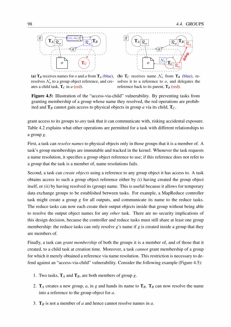
98 4.4. GROUPS
TA TB
TC
g
a
o
Na , N0
Ro Ra
(a) TB receives names for o and a from TA (blue),resolves Na to a group object reference, and cre-ates a child task, TC in a (red).
TA TB
TC
g
a
o No
Ro Ra Ro
Ro
deleg
.
(b) TC receives name No from TB (blue), re-solves it to a reference to o, and delegates thereference back to its parent, TB (red).
Figure 4.5: Illustration of the “access-via-child” vulnerability. By preventing tasks fromgranting membership of a group whose name they resolved, the red operations are prohib-ited and TB cannot gain access to physical objects in group a via its child, TC.
grant access to its groups to any task that it can communicate with, risking accidental exposure.Table 4.2 explains what other operations are permitted for a task with different relationships toa group g.
First, a task can resolve names to physical objects only in those groups that it is a member of. Atask’s group memberships are immutable and tracked in the kernel. Whenever the task requestsa name resolution, it specifies a group object reference to use; if this reference does not refer toa group that the task is a member of, name resolutions fails.
Second, a task can create objects using a reference to any group object it has access to. A taskobtains access to such a group object reference either by (i) having created the group objectitself, or (ii) by having resolved its (group) name. This is useful because it allows for temporarydata exchange groups to be established between tasks. For example, a MapReduce controllertask might create a group g for all outputs, and communicate its name to the reduce tasks.The reduce tasks can now each create their output objects inside that group without being ableto resolve the output object names for any other task. There are no security implications ofthis design decision, because the controller and reduce tasks must still share at least one groupmembership: the reduce tasks can only resolve g’s name if g is created inside a group that theyare members of.
Finally, a task can grant membership of both the groups it is a member of, and of those that itcreated, to a child task at creation time. Moreover, a task cannot grant membership of a groupfor which it merely obtained a reference via name resolution. This restriction is necessary to de-fend against an “access-via-child” vulnerability. Consider the following example (Figure 4.5):
1. Two tasks, TA and TB, are both members of group g.
2. TA creates a new group, a, in g and hands its name to TB. TB can now resolve the nameinto a reference to the group object for a.
3. TB is not a member of a and hence cannot resolve names in a.

CHAPTER 4. DIOS: A DISTRIBUTED OPERATING SYSTEM FOR DATA CENTRES 99
4. Assume that TB was to be allowed to grant membership of a to a child task TC that itcreates.
5. TC can now resolve a name in a that was handed to it by TB (since TC is a member of a)and subsequently delegate a resulting reference back to TB.
This effectively grants TB the same power as TC. Hence, TB’s abilities are equivalent to thoseof a member of a via collusion with its own child, TC. Restricting child task membership to theparent task’s group memberships and those groups that it created solves this problem.
Groups limit the scope of name resolution, but DIOS tasks have another way of restricting accessto objects, implemented via references. In the next section, I describe references in detail.
4.5 References
While names are globally meaningful identifiers for objects, references are handles that areonly valid in a particular context. Unlike names, they cannot be stored as data or communicateddirectly, but they allow interaction with the object they describe (§3.5).
The closest functional analogy for references in POSIX terms are file descriptors (FDs). BothFDs and references are handles for objects and associated kernel state, but FDs can only referto local not remote objects. Moreover, FDs merely serve as plain identifiers, while referencescarry additional information that makes objects translucent to applications.
Mach’s [ABB+86] ports have some similarities with DIOS references: they are location-transparenthandles for local or remote objects, owned by a Mach “task”. However, unlike DIOS references,they are fully transparent rather than translucent, and only support streaming message-passingsemantics with an active task at the far end handling incoming messages, while DIOS referencescan refer to passive objects.
A DIOS reference is a segregated capability that consists of two parts: (i) privileged informationonly available within the TCB, and (ii) public information that is exposed to the task. This divi-sion is required to track protected, privileged state only visible to the TCB (such as the logicalobject’s internal names), while maintaining translucency. Figure 4.6 illustrates this structurewith reference to an example.
The privileged information includes the logical object name, as well as pointers to the publicinformation, to the owning task object, to lists of outstanding read and write I/O requests (§3.7),and a pointer to the object structure. In DIOS, this part of the reference is stored in kernelmemory (bottom half of Figure 4.6).
In addition, the reference also contains public, translucent information, which contains read-only meta-data about the object. This information includes properties that an application might

100 4.5. REFERENCES
ID: 37571470232Type: PRIVMEM_BLOBProximity: localPersistent: falsePermissions: rw-dtVersion: 105 ...
kernel
user
Name: NoPublic reference:Owner:Read requests:Write requests:Object:
ID: 37571470232Type: PRIVMEM_BLOBProximity: localPersistent: falsePermissions: rw-dtVersion: 105 ...
task
object
read-only memory mapping
Figure 4.6: Structure of a DIOS reference illustrated by the example of a physical in-memory data object in, e.g. the web service back-end in Figure 3.3.
consider when choosing between references to alternative physical objects for the same logicalobject (e.g. proximity and persistence), or when checking the consistency of an I/O request onthe physical object referenced (e.g. the version number). This public part of a reference is storedin virtual memory that is mapped read-only into the task’s virtual address space. This permitsthe kernel to update the public information without writing to an application-allocated buffer.
4.5.1 Attributes
DIOS maps the public part of a reference (Ro for object o) into the task’s virtual address space(Figure 4.6) and returns a pointer to this structure from the reference-creating system call. Thus,the public attributes are visible to the application task holding the reference, but cannot bemodified by it.
References’ public attributes enable applications to implement their own policies in the dis-tributed system while still using DIOS abstractions. Consider an example: a MapReduce appli-cation’s map tasks may run on machines where their input data are already in memory, on disk,or not available at all. The map tasks prefer to work on local data rather than a remote copy. Ifthe data are already in memory (e.g. because another job with the same input is running), theapplication prefers to re-use the in-memory copies.
Listing 4.3 shows an example implementation of a pick_input_ref() function for the MapRe-duce application: here, the application policy is to choose in-memory inputs over on-disk inputsregardless of their location, but it prefers more proximate inputs when they are otherwise equal.

CHAPTER 4. DIOS: A DISTRIBUTED OPERATING SYSTEM FOR DATA CENTRES101
1 dios_ref_t* pick_input_ref(dios_ref_t** refs, int count) 2 dios_ref_t* best_ref = refs[0]; /* default: first reference */3
4 for (int i = 1; i < count; ++i) 5 /* always prefer in-memory over on-disk objects */6 if (best_ref->type == DURABLE_BLOB && refs[i]->type == SHMEM_BLOB)7 best_ref = refs[i];8 /* prefer more proximate objects */9 else if (closer_than(refs[i]->proximity, best_ref->proximity))
10 best_ref = refs[i];11 12
13 return best_ref;14
Listing 4.3: Example of using DIOS reference attributes to choose the best input for aMapReduce map task: here, in-memory objects are always preferred over on-disk objects,no matter if local or remote; and more proximate objects are preferred at equal persistence.
In practice, the choice between different references is typically made in libraries rather thanin application code written by the infrastructure user. The DIOS standard library, for example,offers several default reference pickers, which can choose the most proximate reference, or theone with the fewest overlapping fault domains.
Since a reference’s public attributes are read-only, the task cannot directly modify them. Theonly way to mutate reference attributes is to delegate the reference, which creates a new ref-erence with modified attributes. A task can either delegate the new reference back to itself,or delegate it to another task. Some reference attributes, however, are inherent features of theunderlying object (e.g. its type), and cannot be changed on delegation. Others are mutable, butcannot be modified arbitrarily. One such example is the set of permissions on a reference: atask may remove permissions when delegating a reference, but cannot add them.
Next, I describe how tasks first acquire references, followed by how they can be delegated.
4.5.2 Acquisition
A task may acquire a reference in one of three ways. Each of these ways always creates afresh reference, even if the task already holds a reference to the same object. Applications can,however, inspect the object ID (a random 64-bit integer) exposed as part of the public referenceattributes to detect if multiple references refer to the same physical object.
First, each task is provided with an initial set of references at startup, including default refer-ences (a self-reference to the task object and a console reference), as well as pre-specified inputsand outputs. This is useful to execute tasks whose reference set is fixed at execution time.
Second, a task may resolve a name to one or more references. This allows dynamically ac-

102 4.5. REFERENCES
On delegation...Attribute automatically adapted mutable by user copy on mutationType 7 7 –Group 7 7 –Read version (vr) 7 7 –Write version (vw) 7 7 –Active readers (ar) 3 7 –Active writers (aw) 3 7 –R/W buffer size 3 7 –Permissions 7 3, restrict only 7
Concurrent access mode 7 3† if incompatibleI/O multiplexing mode 7 3† if incompatiblePersistence 7 3† 3
Proximity 3 3† 3
Table 4.3: Examples of DIOS reference attributes and their mutability properties. Proper-ties with a 3† can be changed by the user on delegation, but this results in a new physicalobject, copying the object’s data.
quired data to be converted into references to physical objects. I covered name resolution inSection 4.3.3.
Third, the task may receive a reference from another task through delegation. This is useful inorder to grant selective access to an object. I describe reference delegation next.
4.5.3 Delegation
As I explained in Section 4.3.3, resolving an object’s name yields a fully privileged reference toit. DIOS tasks also often need to grant selective access, i.e. access with restricted permissions,to objects. DIOS therefore supports another, restricted way of sharing an object between taskseven in the absence of the group membership required to resolve its name.
To enable such sharing, references must be able to traverse task boundaries. This process, whichinvolves the DIOS TCB, is called delegation. A delegation of Ro from TA to TB makes DIOS
generate a new reference that refers to the same physical object as Ro. The public and privateparts of the new, delegated reference, Rd , are identical to those of Ro, except for transformationspecific to TB’s context.
The transformation is important: since references are handles that carry context-dependent in-formation, a delegated reference cannot merely be copied into the target task’s reference table.Instead, the delegated reference must be adapted appropriately when exchanged between tasks.As part of this transformation, context-dependent reference attributes are changed to reflect theview of its target object from the perspective of the receiving task. For example, the “proximity”attribute is adapted to “remote” if TB is on a different machine to the object o.
Some attributes can also be explicitly transformed by the user when delegating a reference:

CHAPTER 4. DIOS: A DISTRIBUTED OPERATING SYSTEM FOR DATA CENTRES103
restricting permissions is a key example. The user can pass appropriate flags to the referencedelegation to change these attributes. In some cases, changing an attribute has the side-effectof creating a new physical object and copying the object’s data (if applicable). For example,if the “persistence” attribute on a reference to an ephemeral in-memory object is changed to“durable” on delegation, a durable copy of the object is made.
Table 4.3 shows a selection of attributes that the public part of a reference exposes, and indicateswhether they are static, automatically adapted, or can be mutated by the user on delegation.Further extensions of this set, or even support for application-defined attribute labels, are likelyto be useful for applications to take full advantage of “translucent” objects.
Notifying the recipient task. When a task delegates a reference to another task, DIOS insertsit into the receiving task’s reference table, but the target task itself is initially unaware of thenew reference. Since applications identify a reference to object o by its public part, Ro, therecipient task cannot perform any system calls on the new reference until it has been informedabout its public part’s location.
However, each DIOS task has access to a special default reference to its own task object, the“self-reference”. This reference acts as a stream of event notifications, which can supply point-ers to newly delegated references. Tasks can choose to ignore these events, or have to poll theself-reference for delegated references.7
4.6 System call API
The DIOS system call API defines how applications interact with the local TCB. The DIOS
system call API is centred around the name, group and reference abstractions described inSections 4.3–4.5. Table 4.4 shows the current API, which consists of thirteen system calls thatcover I/O, object, and task management. These thirteen calls are sufficient to implement keydata centre applications efficiently and with strong compartmentalisation guarantees.
The DIOS API is similar to subsets of the ABIs in Drawbridge [PBH+11, §4], Bascule [BLF+13,§3.1], and Embassies [HPD13, Fig. 2]. However, it is not necessarily complete or universal:further extensions may be required for specific use cases. Alternatively, DIOS system calls canbe combined with legacy Linux system calls in the same program, as I discuss in Section 4.10.3.
In the following, I discuss the general properties and semantics of the DIOS system calls.
Blocking and synchrony. Handling a DIOS system call can require communication acrossthe data centre interconnect, and can take a long time compared to a local system call (on the
7A callback notification mechanism akin to conventional Unix signals, where a task registers a callback tobe invoked on incoming reference delegation, would avoid the need to poll. However, it would require anotherabstraction to be added to DIOS.
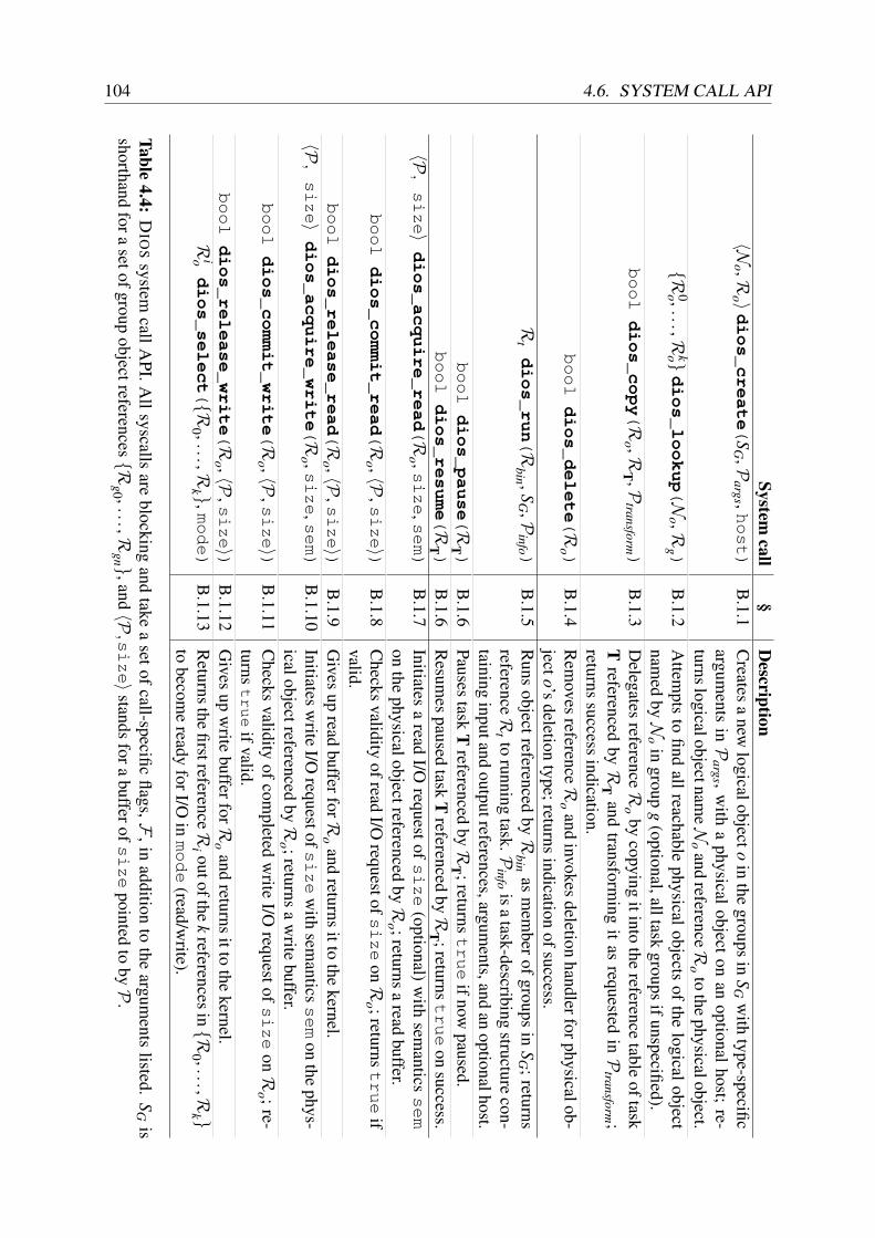
104 4.6. SYSTEM CALL APISystem
call§
Description
〈No ,R
o 〉dios_create(
SG ,P
args ,host)
B.1.1
Creates
anew
logicalobjectoin
thegroups
inS
Gw
ithtype-specific
arguments
inP
args ,w
itha
physicalobject
onan
optionalhost;
re-turnslogicalobjectnam
eNo
andreferenceR
oto
thephysicalobject.
R0o ,...,R
ko dios_lookup(N
o ,Rg )
B.1.2
Attem
ptsto
findallreachable
physicalobjectsof
thelogicalobject
named
byN
oin
groupg
(optional,alltaskgroups
ifunspecified).booldios_copy(R
o ,RT ,P
transform)
B.1.3
Delegates
referenceR
oby
copyingitinto
thereference
tableoftask
Treferenced
byR
Tand
transforming
itas
requestedin
Ptransform ;
returnssuccess
indication.booldios_delete(R
o )B
.1.4R
emoves
referenceRo
andinvokes
deletionhandlerforphysicalob-
jecto’sdeletion
type;returnsindication
ofsuccess.R
tdios_run(R
bin ,SG ,P
info )B
.1.5R
unsobjectreferenced
byR
binas
mem
berof
groupsin
SG ;returns
referenceRt to
runningtask.P
infois
atask-describing
structurecon-
taininginputand
outputreferences,arguments,and
anoptionalhost.
booldios_pause(R
T)
B.1.6
Pausestask
Treferenced
byR
T ;returnstrue
ifnowpaused.
bool
dios_resume(R
T)
B.1.6
Resum
espaused
taskT
referencedby
RT ;returns
true
onsuccess.
〈P,size〉
dios_acquire_read(R
o ,size,s
em)
B.1.7
Initiatesa
readI/O
requestofsize
(optional)w
ithsem
anticssem
onthe
physicalobjectreferencedby
Ro ;returns
aread
buffer.bool
dios_commit_read(R
o ,〈P,size〉)
B.1.8
Checks
validityofread
I/Orequestof
size
onR
o ;returnstrue
ifvalid.
bool
dios_release_read(R
o ,〈P,size〉)
B.1.9
Gives
upread
bufferforRo
andreturns
ittothe
kernel.〈P
,size〉
dios_acquire_write(R
o ,size,s
em)
B.1.10
Initiatesw
riteI/O
requestofsize
with
semantics
sem
onthe
phys-icalobjectreferenced
byR
o ;returnsa
write
buffer.bool
dios_commit_write(R
o ,〈P,size〉)
B.1.11
Checks
validityof
completed
write
I/Orequestof
size
onR
o ;re-turns
true
ifvalid.bool
dios_release_write(R
o ,〈P,size〉)
B.1.12
Gives
upw
ritebufferforR
oand
returnsitto
thekernel.
Riodios_select(R
0 ,...,Rk ,m
ode)
B.1.13
Returnsthe
firstreferenceRi outofthe
kreferencesin
R0 ,...,R
k to
become
readyforI/O
inmode
(read/write).
Table4.4:
DIO
Ssystem
callAPI.A
llsyscallsare
blockingand
takea
setofcall-specific
flags,F,in
additionto
theargum
entslisted.
SG
isshorthand
forasetofgroup
objectreferencesRg0 ,...,R
gn ,and〈P
,size〉
standsfora
bufferofsize
pointedto
byP
.

CHAPTER 4. DIOS: A DISTRIBUTED OPERATING SYSTEM FOR DATA CENTRES105
1 [...]2 /* Pull data from the mappers */3 dios_ref_t* selected_ref = NULL;4 int num_inputs_done = 0, ret = 0;5
6 do 7 ret = dios_select(D_NONE, task_info.input_refs, task_info.input_count,8 &selected_ref, D_SELECT_READ);9 if (ret || !selected_ref)
10 return ret;11
12 /* Get input data from ref returned by dios_select(2) */13 ret = reduce_read_input(selected_ref);14 if (ret == -EEOF)15 num_inputs_done++;16 else if (ret != -EAGAIN)17 return ret;18 while (num_inputs_done < cfg_.num_mappers_);
Listing 4.4: Input multiplexing logic in the MapReduce example: dios_select(2)
blocks and returns the reference to the first mapper output stream object that has data avail-able.
order of hundreds of microseconds, as opposed to tens). All DIOS I/O is synchronous, andits system calls are therefore blocking. Blocking the calling task while waiting for a remoteoperation allows other tasks to run in the meantime, and thus increases the effective resourceutilisation.
Non-blocking variants of some system calls could be added to cater to applications that cannottolerate blocking. In addition, asynchronous abstractions can be implemented in user-spaceprograms using the dios_select(2) system call to multiplex I/O over multiple references, asillustrated in Listing 4.4.
Memory allocation. POSIX-like system call APIs typically expect user-space to allocate allmemory that backs pointers passed through the system call API (with the exception of allocatingcalls like brk(2) and mmap(2)). DIOS takes a slightly different approach: object names andinitialisation arguments (both of which are themselves data) must be backed by existing user-space memory, while all other pointer arguments (I/O buffers and references) must refer tokernel-allocated, ownership-tracked structures. These must have previously been passed touser-space from either (i) a reference-creating system call (for references), or (ii) the buffer-creating dios_acquire_read(2)/dios_acquire_write(2) calls (for I/O buffers). Thisallows the OS to validate the integrity of the pointers passed to the kernel, and simplifies theimplementation of zero-copy I/O requests.

106 4.7. I/O REQUESTS
Handling failures Failures of components, machines, or network links are a common occur-rence in a data centre. DIOS must therefore accommodate such failures: it must either handlethem itself, or indicate to applications that they occurred.
In accordance with my model, DIOS leaves handling failures to applications, since applications’policies for different types of failures can differ substantially. It indicates detectable failures byreturning an appropriate error codes from system calls, and it is the application’s responsibilityto check for such errors (as it is with legacy system calls). For example, if the remote physicalobject that a reference refers to has become inaccessible due to a network or machine failure,DIOS returns an EHOSTUNREACH error, rather than transparently substituting another physicalobject.
Some errors, however, can be recovered from without the user-space application having to beinvolved or aware: for example, RPCs involved in remote operations are retried a configurablenumber of times before failing to avoid heavy-handed handling of temporary outages.
A detailed description of each system call’s arguments and semantics can be found in Ap-pendix B.1. In the next section, I describe the implementation of DIOS I/O requests.
4.7 I/O requests
In Section 3.7, I described how the decentralised data centre OS model uses I/O requests tosupport concurrent access to local and remote physical objects.
The I/O request model can offer many different concurrent access semantics, but DIOS restrictsitself to the relatively simple options shown in Table 4.5. The four levels are exclusive ac-cess (EXCL), multiple-reader, single-writer (MRSW), single-reader, multiple-writer (SRMW), andunrestricted (ANY).8
To enforce these concurrent access semantics, DIOS keeps four atomic counters for each object:
1. the number of active read requests on the object, ar;2. the number of active write requests on the object, aw;3. the read version number, vr; and4. the write version number, vw.
ar and aw are incremented when the acquire for a new I/O request is handled, and decrementedonce the commit stage has finished; vr and vw are incremented on successful commit of a read orwrite request, respectively. The counter updates and the application of changes on committinga write request are performed under local mutual exclusion. If necessary, the scalability of thisstep could be further improved using well-known techniques for scalable counters [ELL+07;CKZ13, §3.1] and deferred updates (e.g. lazily reconciling copy-on-write pages).
8SRMW semantics, while somewhat unusual, are useful e.g. for an application that reads and decodes variable-length requests from a buffer and multiplexes them to handlers that write the responses to predefined offsets.

CHAPTER 4. DIOS: A DISTRIBUTED OPERATING SYSTEM FOR DATA CENTRES107
Level Readers Writers MeaningEXCL 1 (either) Mutual exclusion (sequential consistency).MRSW ∗ 1 Multiple-reader, single-writer (cannot corrupt data).SRMW 1 ∗ Single-reader, multiple-writer (cannot read stale data).ANY ∗ ∗ Any access allowed, no consistency guarantee.
Table 4.5: The four concurrent access semantics supported by I/O requests based on simpleread/write versions and reader/writer counters.
TA
TB
ACQ 3 COMM 3
ACQ 3 COMM 3
(a) Disjoint requests both succeed.
TA
TB
ACQ 3 COMM 7
ACQ 3 COMM 3
(b) TA fails on commit as ar = 2.
TA
TB
ACQ 7
ACQ 3 COMM 3
(c) TA fails on acquire as ar = 1.
TA
TB
ACQ 3 COMM 7
ACQ 3 COMM 3
(d) TA fails as TB has increased vr.
Figure 4.7: Two read requests with different concurrent access semantics attempt to accessobject o: TA requests exclusive access and TB requests MRSW semantics. Depending onhow the requests align, TA may fail at the acquire or commit stages.
In addition to the high-level indication as to whether an I/O request succeeded or failed, DIOS
also exposes these “raw” version counters via reference attributes. This enables custom consis-tency policies spanning multiple I/O requests to be implemented at the application level.
Examples. To illustrate I/O requests, consider the example of two tasks (TA and TB) bothaccessing a blob object in shared memory. Assume that both tasks initiate a read-only I/Orequest, with TA specifying EXCL as its desired access semantic, while TB specifies MRSW.Figure 4.7 shows several different ways in which the requests may execute. Since TA’s requestasks for exclusive access semantics, it fails in all situations apart from the disjoint schedule inFigure 4.7a. Note that if TA’s request was a write, TB would fail on acquire in Figure 4.7b.
Listing 4.5 shows another example: the implementation of an update operation in a key-valuestore (an in-memory blob) under exclusive access. Here, dios_commit_write(2) indicatesif any concurrent reads or writes have taken place between the dios_acquire_write(2) calland the commit. If so, the code re-acquires and keeps trying until a valid write is completed.This implementation starves writers under high contention, but a higher-level lock primitive canbe implemented using I/O requests to ensure progress.
Higher-level abstractions. The I/O request system can also be used to implement higher-level concurrent access abstractions, such as synchronisation primitives across tasks, e.g. for acoordination service like Chubby [Bur06] or Zookeeper [HKJ+10].
For example, a global mutex can be implemented via I/O requests on a “lock” object that stores a

108 4.7. I/O REQUESTS
1 void set_value_excl(dios_ref_t* val_ref, char* new_value, int val_size) 2 dios_iovec_t* iov = NULL;3 int ret = 0;4 /* Set up write with buffer */5 dios_acquire_write(val_ref, D_ACQUIRE_WRITE_IOV_CREATE, &iov);6 do 7 ret = dios_acquire_write(D_ACQUIRE_WRITE_IOV_REUSE,8 val_ref, val_size, &iov, D_IO_EXCL);9 /* Try again if we failed to acquire at EXCL */
10 if (ret < 0)11 continue;12 /* Modify data ... */13 memcpy(iov->buf, new_value, val_size);14 /* Check for concurrent modification */15 ret = dios_commit_write(D_COMMIT_WRITE_IOV_USE, val_ref,16 val_size, iov);17 if (ret == 0)18 /* Write was valid under EXCL concurrent access, done */19 break;20 while (true);21 /* De-allocate buffer */22 dios_release_write(D_NONE, val_ref, &iov);23
Listing 4.5: Setting a backend key-value store entry’s value via a DIOS I/O request withexclusive (EXCL) concurrent access: modification of val_ref is retried until it applieswithout any readers or writers present.
value representing locked or unlocked states. To obtain the lock, an application first performsa read I/O request with exclusive access semantics. If this request succeeds and the mutex valueis set to unlocked, the application records vr and vw, and initiates an exclusive write request toset the value to locked. If the version numbers r′w and v′w returned from acquiring this requestare equal to the vr and vw recorded earlier, atomicity is guaranteed, and if they differ, the lockacquisition fails. Thus, if the write request succeeds, indicating that no other concurrent writeshappened, the mutex is acquired.
Some more complex, multi-object abstractions require “happens-before” relationships on re-quests issued by different tasks. I/O requests on their own do not provide such an orderingrelationship because they are decentralised. However, an application can implement e.g. Lam-port clocks [Lam78] via I/O requests, and thus enforce a partial ordering on events. Once ahappens-before relationship is established, multi-replica consistency schemes such as versionclocks (cf. Dynamo [DHJ+07]) and causal consistency [BGH+13] can be implemented.
Buffer management. I/O requests work with data in buffers. To initiate an I/O request, theapplication acquires a buffer and asks the kernel to set up request state. Subsequently, theapplication performs its I/O on the buffer and eventually commits the request. At this point, the

CHAPTER 4. DIOS: A DISTRIBUTED OPERATING SYSTEM FOR DATA CENTRES109
acquired committed releasedacquire commit release
commit
acquire
Figure 4.8: Stages of a DIOS I/O request and transitions between them.
1 [...]2 /* Read chunk size prefix */3 ret = dios_acquire_read(size_buf ? D_ACQUIRE_READ_IOV_REUSE : D_NONE,4 input_ref, sizeof(uint64_t), &size_buf, D_ANY);5 if (ret < 0)6 return ret;7 /* Got an incoming chunk size */8 uint64_t read_size = *(uint64_t*)size_buf->buf;9 ret = dios_commit_read(D_NONE, input_ref, size_buf);
10 if (ret < 0)11 return ret;12 /* Can’t re-use data buffer if it’s too small */13 if (read_size > data_buf->len) 14 dios_release_read(D_NONE, input_ref, data_buf);15 data_buf = NULL;16 17 /* Get the actual data chunk */18 ret = dios_acquire_read(19 data_buf ? D_ACQUIRE_READ_IOV_REUSE : D_ACQUIRE_READ_IOV_CREATE,20 input_ref, read_size, &data_buf, D_ANY);21 if (ret < 0)22 return ret;23 /* Process input data from mapper */24 [...]
Listing 4.6: Excerpt from the reducer’s input processing logic in the MapReduce example:the size buffer (size_buf) and the data buffer (data_buf) are re-used to amortise the costof buffer allocation and memory mapping.
buffer could be de-allocated if the request succeeded. However, if further I/O must be done onthe same object, or if the request failed, releasing the buffer would be wasteful. Instead, thebuffer should be reuseable for further I/O until explicitly released.
Therefore, I extend the simple acquire–commit sequence with an additional release step andseveral extra transitions (Figure 4.8). After attempting to commit, the task may either (i) initiatea new I/O request on the same buffer by repeating the acquire step; (ii) attempt to commit thesame buffer again; or (iii) release the buffer back to the kernel. In other words, a DIOS I/Orequest must acquire and commit at least once, but may subsequently commit any number oftimes. It may also start a new request using the same buffer by repeating the acquire stage;finally, it must release the buffer exactly once.

110 4.8. DISTRIBUTED COORDINATION
Listing 4.6 shows a practical example of this buffer re-use in a MapReduce reducer’s inputprocessing code, where buffers are re-used across I/O requests to amortise setup costs.
On a single machine, the DIOS I/O request implementation is straightforward. Across ma-chines, however, additional communication is required to coordinate the requests and to movedata into the appropriate buffers. In the next section, I discuss how DIOS implements this com-munication.
4.8 Distributed coordination
A physical DIOS object exists on a particular machine, but can be interacted with across ma-chine boundaries. Hence, DIOS must coordinate operations and ship data between machines.Two types of communication exist: coordination and data transmission. Examples of coor-dination include creation and deletion of names and references, the delegation of references,task creation, and reference meta-data updates – all of which are typical “control plane” opera-tions. Data transmission, by contrast, involves the exchange of bulk data for I/O requests (“dataplane”), and its volume usually exceeds that of coordination traffic.
Both types of communication are implemented and executed by the machine kernels in DIOS.Involvement of at least one kernel is required for coordination, since messages must passthrough the TCB for authentication and access control; however, alternative designs that onlyinvolve the source or destination kernel are conceivable.
Coordination. DIOS implements operations that coordinate different kernels via the DIOS
Coordination Protocol (DCP). The DCP is a binary RPC protocol over reliable datagrams,implemented using Reliable Datagram Sockets (RDS) [RDS15]. RPC messages are encodedusing Protocol Buffers and handled by a DCP kernel thread on each machine.
DCP RPCs are time-critical and their synchronous execution requires low end-to-end low la-tency. In Section 5.2.3, I show that DCP RPCs usually achieve round-trip times under 200microseconds; other work has shown that RPC latencies of tens of microseconds are feasibleusing commodity hardware [ORS+11].
Most DCP messages are sent directly to the destination machine. However, since DIOS im-plements a distributed name service (see §4.3.3), it requires a broadcast primitive. While anexisting network layer broadcast primitive could be used (e.g. UDP broadcast), such primitivesdo not typically offer reliable delivery. Instead, DIOS uses a best-effort peer registration proto-col over broadcast UDP, and implements broadcast lookups by sending coordination messagesto all live peers. The downside of this approach is that it sends p messages for p live peers, du-plicating the content of each message. To reduce this overhead, DIOS could use UDP broadcast

CHAPTER 4. DIOS: A DISTRIBUTED OPERATING SYSTEM FOR DATA CENTRES111
release_write
commit_write
acquire_write
release_read
commit_read
acquire_read
select
pause/resume
copy
run
delete
lookup
create
create 3 3 3 3 3 3 3 3 3 3 3 (∗) 3
lookup 3 (∗) (∗) 3 (∗) (∗) 3 (∗) (∗) 3 (∗) 3
delete 3 (§) 3 (§) (‡) (†) (†) (†)run 3 (§) 3 3 3 3 3 3 3 3
copy 3 (§) (∗) 3 (∗) (∗) 3 3 3
pause/resume 3 3 3 3 3 3 (‡) 3
select 3 (‡) 3 3 (‡) 3 (‡)acquire_read 3 (§) (§) 3 (§) (§)commit_read 3 (§) (§) 3 (§)release_read 3 (§) (§) 3
acquire_write 3 (§) (§)commit_write 3 (§)
release_write 3
Calls are always idempotent.Race has no effect; arguments and returns of calls always necessarily disjunct.Race okay; appropriate failure indication returned if operation impossible.
3 Always commutative: re-ordering produces no observable effect.(∗) May return a stale or incomplete reference set, or out of date reference attributes.(†) Logical object deletion not guaranteed even if delete(2) on last physical object.(‡) dios_select(2) outcome may vary non-deterministically.(§) Application must handle I/O concurrency semantics.
Figure 4.9: Re-order correctness matrix for DIOS system calls. The colour of a cell indi-cates why a race does not affect correctness, while the symbol indicates whether the callsalways commute, or – if not – which observable differences in outcome may occur.
over a QJUMP network, which guarantees reliable delivery and a hard upper bound on latencyin the absence of hardware failures [GSG+15].9
Unlike reliable delivery, ordering of DCP RPCs is not required for correct operation: DIOS
does not impose any ordering semantics in the system call API. Re-ordering can occur if twosystem calls race within a machine or across the data centre network.
Figure 4.9 illustrates the effect of pairwise system call re-ordering on observability (of the re-ordering) and correctness (of the outcome). Many system calls are idempotent, independent orcan always be re-ordered without observable effect, i.e. they are always commutative. Some do– under certain circumstances, e.g. when invoked on the same reference – produce observablydifferent results when re-ordered (i.e. they are not always commutative), but all such outcomes
9Centralised coordination, e.g. as in Fastpass [POB+14], could also be employed, but requires ahead-of-timecoordination for sending coordination messages; QJUMP requires no ahead-of-time coordination.

112 4.8. DISTRIBUTED COORDINATION
M0 M1
user
kernelbuf
o
buf
Han
dler
thre
ad
vr : 3vw : 5
ACQ_WR
ACQ: 3
COMM_WR
COMM: 3
DC
P
DC
P
I/O I/O1
2
3
4
5
Figure 4.10: Handling write I/O request for a remote object: the task on M0 first acquires(ACQ_WR) via RPC to M1 and receives a buffer for local I/O; it then attempts to commit therequest (COMM_WR), the data are sent via the transport object, a remote kernel thread handlesthe request, validates it, and applies the changes from the buffer.
are permissible under the DIOS API semantics, and must be handled by the application.
This lack of ordered messaging semantics differentiates the DCP from group communicationprotocols employed in classic distributed operating systems: for example, all messages to agroup in Amoeba are sequenced by a regularly elected leader [KT91].
Data transmission. The DCP is only used for small coordination messages. Bulk data trans-mission for remote I/O is the responsibility of transport objects. Transport objects are localphysical proxy objects for a remote physical target object, which match the target object’s I/Osemantics. This approach is similar to the implementation of remote I/O in classic distributedoperating systems (e.g. in V [Che88]): a remote kernel thread acts as an I/O proxy for theoriginator task, reading data or applying writes received.
DIOS transport objects are supported by an underlying TCP connection to the kernel on themachine that holds the physical object. In response to DCP messages, I/O data are sent viathis TCP connection.10 The transport object abstraction, however, also supports other means ofcommunication: for example, an RDMA mapping might be used if RDMA is available.
Remote I/O example. Figure 4.10 illustrates DIOS remote I/O with an example. The taskon machine M0 starts a write I/O request on physical object o by making an acquire systemcall. The kernel coordinates with the kernel on M1 (via the DCP), first issuing an RPC for M1’skernel to check the version and request counters for o. If the request can be admitted accordingto the desired concurrent access semantics, the kernels establish a connection via a transportobject (e.g. a TCP connection or an RDMA mapping) and a buffer is returned to user-space
10The current implementation uses per-object connections; to scale to more objects, it would multiplex multipleobjects’ I/O data onto one TCP connection between each pair of hosts. This would require at most as many TCPconnections as existing data centres must support. However, connection sharing comes at the cost of reducedmulti-core scalability within a machine. A high-performance datagram-oriented protocol that can be implementedscalably [Cle14, p. 40] might solve this issue.

CHAPTER 4. DIOS: A DISTRIBUTED OPERATING SYSTEM FOR DATA CENTRES113
on M0. The application deposits its data in the buffer or modifies its contents, and invokesthe commit system call. M0’s kernel now uses the transport object to send the buffer to M1,where an I/O handler thread in the kernel checks the request’s validity and applies the write too, synchronising with local or other remote I/O requests as required.
4.9 Scalability
Scalability is a design goal for DIOS, as it runs many tasks across many machines in a datacentre. DIOS also aims to address some of the inherent scalability limitations of legacy, single-machine POSIX abstractions observed in prior work [CKZ+13, §4]. In the following, I infor-mally explain how DIOS abstractions support scalability by design.
1. The system call API avoids serialising API constructs and allows for non-deterministicidentifier choices to be made by the kernel: for example, the flat names and randomlychosen reference IDs are taken from unordered sets of identifiers and are independent ofeach other (unlike, say, monotonically increasing POSIX FD numbers).
2. The design avoids unscalable data structures: for example, the reference tables areprivate to each task, and both they and the shared name table are hash tables that lendthemselves to scalable concurrent access via fine-grained locking [Cle14, p. 14].
3. Weak ordering is permissible for many DIOS system calls: I discussed the re-orderingproperties of DIOS system calls in the previous section, and showed that calls either (i)are always idempotent, (ii) are necessarily invoked on different arguments, or (iii) that arace appropriately fails one of the racing calls. Even data-dependent I/O requests may bere-ordered and overlapped if the application-level consistency policy permits it.
4. Resources are released asynchronously: for example, the deletion of objects, references,and names can take place asynchronously, as user-space code cannot immediately reusean identifier (references, unlike POSIX FDs, do not re-use IDs). Kernel-allocated I/Obuffers (§4.7) also enable asynchronous release: the resources may be torn down afterdios_release_read(2) and dios_release_write(2) return without any risk ofthe buffer being re-used in user code.
5. Some of the DIOS abstractions decompose compound operations compared to legacysystem calls: for example, spawning a task via dios_run(2) does not have the com-pound fork(2)/exec(2) semantics that the Linux system call API requires, but is moreakin to the (scalable) posix_spawn(2).
The practical scalability of the DIOS implementation is affected by the underlying Linux ker-nel’s scalability. However, the above principles are conducive to commutative implementationsof operations even if they do not commute in the Linux kernel today. I discuss in Section 9.1.2hows this might be attempted in future work.

114 4.10. LINUX INTEGRATION
4.10 Linux integration
I developed DIOS as an extension module for the Linux kernel in order to support legacy appli-cations, enable incremental migration, and to keep the implementation effort manageable.
This section describes the DIOS implementation, which consists of a portable core module andan integration module for the Linux host kernel. By adding an appropriate integration module,DIOS could support host kernels other than Linux (see §9.1.2).
In Section 4.10.1, I describe the necessary changes to the core Linux kernel, and show that onlyminimal changes are required. Following, I describe the implementation of the DIOS modulesin Section 4.10.2. The integration of DIOS with Linux allows incremental migration of existingapplications, and I discuss this in Section 4.10.3.
4.10.1 Linux kernel changes
The host kernel – Linux, in my implementation – must supply generic kernel functionalitythat DIOS requires: drivers for machine hardware, bootup code, a network stack, and low-levelmemory management code. Since this code is not DIOS-specific, it makes sense to re-use stable,mature kernel code, and build the DIOS abstractions on top.
To deploy DIOS, a small number of changes to the core Linux kernel code were required:
System call handlers for the new DIOS system calls had to be added. These require a kernelpatch because Linux does not allow loadable kernel modules to rewrite the syscall table.
Process control block extensions are required to differentiate DIOS tasks from legacy pro-cesses at runtime, in order to limit each to the correct set of system calls.
Process entry and exit code had to be amended to call into the initialisation and destructionroutines for DIOS tasks, which handle DIOS-specific state such as the reference table.
The ELF binary loader had to be modified to recognise DIOS binaries and initialise themappropriately.
The necessary changes amount to a patch changing about 500 lines (≈ 0.01% of the non-driverkernel source).11 Table 4.6 lists the changes and their impact.
In addition to the above, DIOS requires a means of reliably delivering messages to remotemachines (§4.8). I implemented this by establishing reliable channels via messaging protocolsalready supported in the Linux kernel: I use existing kernel support for Reliable DatagramSockets (RDS) for DIOS coordination messages. RDS supports Infiniband and TCP transports;my experiments use the TCP transport over 10G Ethernet.
11Based on the DIOS patch for Linux kernel v3.14.

CHAPTER 4. DIOS: A DISTRIBUTED OPERATING SYSTEM FOR DATA CENTRES115
Location Linux source file Change
ELF binary loader fs/binfmt_elf.c+13 –0Support ELF brands for DIOS binaries.
Process execution handler fs/exec.c+9 –0Add initialisation code for DIOS tasks.
Process exit handler kernel/exit.c+8 –0Add teardown code for DIOS tasks.
Process control block sched.h+10 –0Add DIOS fields to process meta-data.
System call macros syscalls.h+17 –1Add restrictions on legacy/DIOS syscalls.
System call table syscall_64.tbl+14 –0Add thirteen new system calls.
ELF binary brands uapi/linux/elf.h+16 –9Add new DIOS ELF brands.
System call handlers new (dios/*)+401 –0Forward system calls to module.
Table 4.6: Changes made to the Linux host kernel for DIOS.
4.10.2 DIOS modules
The DIOS abstractions are not inherently tied to any particular host kernel, even though myimplementation uses Linux. DIOS consists of two modules:
1. The DIOS Core Module (DCM), which contains the core DIOS logic (e.g. name andreference tables, system call handlers, capability management), but never invokes anyhost kernel functions directly.
2. The DIOS Adaptation Layer (DAL), which indirects calls into the host kernel (e.g. start-ing a new process, installing memory mappings) to the matching Linux symbols.
DIOS Core Module. The DCM implements the core of DIOS, including the name and refer-ence tables, management and transformation code for names and references, coordination viathe DCP, and handlers for the DIOS system calls. It consists of about 6,900 lines of C code, andrelies on the DAL for invoking Linux kernel functionality.
DIOS Adaptation Layer. The DAL indirects DIOS invocations of host kernel functionalityto Linux-specific symbols. Such functionality includes the creation and execution of user-spaceprocesses (for DIOS tasks), allocation of physical and virtual memory, and mapping of kernelmemory into user-space virtual address spaces (for DIOS references). The DAL also inter-faces with the Linux kernel network stack for remote object access and DCP coordination, andindirects other I/O on block devices and the console. Finally, it provides access to Linux con-currency mechanisms such as worker threads and wait queues, as well as architecture-specificimplementations of locks, semaphores, and atomics.

116 4.10. LINUX INTEGRATION
kernel
user
DIOS AdaptationLayer (DAL)
dal_linux.koDIOS Core Module
(DCM)namt_get(...)
dios.koKernel patch(≈500 LoC)
do_lookup(...)
Linux kernel (host kernel)khash_find(...)
Application tasklookup(2)
Figure 4.11: Structure of DIOS implementation, showing the constituent kernel modulesusing the example of handling a lookup(2) system call: the call (red arrows) is forwardedby the kernel patch to the DCM (dios.ko), which uses the DAL (dal_linux.ko) toinvoke Linux kernel functionality (blue arrows). Dashed arrows show the return path.
Since the DAL is an adaptation layer, it typically wraps an appropriate Linux kernel function,but in some cases maintains extra state (e.g. for work queues). It is fairly compact and consistsof about 3,000 lines of C code.
Example. Figure 4.11 illustrates the roles of the kernel patch, the DAL module, and the DIOS
Core Module using the example of a dios_lookup(2) system call invocation. The systemcall is first invoked in a user-space task and handled by a shim system call handler in the Linuxkernel patch. This handler proxies the system call invocation to the DIOS core module, whichperforms a name table lookup (namt_get()), which in turn relies on the DAL indirectingaccess to the Linux kernel hash table data structure (khash_find()). Finally, the result isreturned to user-space via the shim handler.
4.10.3 Incremental deployment
Unlike research operating systems that support conventional APIs (e.g. subsets of POSIX) viacompatibility layers – such as Mach [ABB+86, §8] or L4 [HHL+97] – the Linux integration ofDIOS allows native execution of legacy applications side-by-side with DIOS applications. Thisenables DIOS to be deployed while applications are incrementally ported to it.
In such a mixed environment, DIOS must however differentiate between process types in orderto (i) initialise, manage, and destruct DIOS-specific state when needed, and (ii) restrict theavailability of DIOS objects and system calls to applications that are permitted to use them.
DIOS can be configured for different degrees of restriction:
• In liberal mode, applications can exist in a “limbo” state that allows them to mix DIOS
objects and legacy OS facilities (e.g. pipes and FDs).

CHAPTER 4. DIOS: A DISTRIBUTED OPERATING SYSTEM FOR DATA CENTRES117
System callsELF brand liberal mode restricted mode Start Access pure
Binary type ABI version legacy DIOS legacy DIOS via DIOS obj.
DIO
S Pure 0xD1 0x05 7 3 7 3 run(2) 3
Limbo 0xD1 0x11 3 3 7 3 run(2) 3 †
Legacy 0xD1 0x13 3 3 3 7 legacy 7
Legacy ELF any other 3 7 3 7 legacy 7
( 3 †: only in restricted mode.)
Table 4.7: DIOS supports four binary types, which have access to different system callAPIs depending on the execution mode, which must be invoked differently and which mayhave limited access to objects.
• In restricted mode, applications must either use only DIOS abstractions, or only legacyones, and cannot mix them inside the same process.
The choice between liberal and restricted mode is global, but a “branding” on binaries permitsdifferent degrees of per-process restrictions. Table 4.7 shows the different types of binariessupported:
Pure DIOS binaries must use DIOS objects and system calls to access data and interact. Theyhave the most aggressive restrictions applied to them, but, in return, are guaranteed to ac-cess only objects for which they have legitimately acquired a reference (see §4.5). Legacyabstractions (and thus possible side-channels) are unavailable.
A good example of a pure DIOS application is a MapReduce worker task, which takesuser-provided lambdas (map() and reduce()) and applies them on inputs to determin-istically generate outputs. The pure DIOS restrictions ensure that the user-provided codecannot leak data via legacy abstractions.
DIOS limbo binaries have the same access to DIOS objects and system calls as pure DIOS
binaries, but they can also make legacy system calls. The must, however, be launched viadios_run(2).
An example limbo application is the Firmament scheduler (Chapter 6), which may useboth legacy and DIOS abstractions: the former for monitoring tasks and the latter (i.e.dios_run(2)) to start DIOS tasks.
DIOS legacy binaries are identical to DIOS limbo binaries, except that they must be executedusing legacy host kernel means (e.g. exec(2)), rather than the dios_run(2) systemcall. This is useful when a legacy process without access to DIOS facilities must start aDIOS-enabled process.
A key use case for DIOS legacy mode is bootstrapping DIOS at startup: for example, thedizibox shell or a local DIOS init process are launched by a legacy process, init. Thisworks in liberal mode; in restricted mode, init itself must be a DIOS binary.

118 4.11. SUMMARY
Non-DIOS legacy binaries execute as if DIOS did not exist. They can only use legacy hostkernel abstractions, and the DIOS namespaces and objects are unavailable to them.
Most legacy utilities fall into this category; examples are system utilities such as mountor init that perform purely local tasks.
In restricted mode, DIOS limbo binaries are treated as pure DIOS binaries (losing their ability toaccess legacy abstractions) and DIOS legacy binaries are treated as legacy binaries (losing theirability to use DIOS abstractions).
To inform the kernel of the type of a given binary on execution, DIOS modifies the Executableand Linking Format (ELF) header [ELF-64], and sets the fields specifying the OS ABI targetedby the binary (EI_OSABI) and the ABI version (EI_OSABIVERSION) to custom values.12
The ability to run different binary types at the same time enables an incremental migration pathfrom legacy abstractions to using DIOS ones.
4.11 Summary
In this chapter, I introduced DIOS, a prototype implementation of the decentralised data centreOS model introduced in Chapter 3.
After an overview (§4.1), I described the key abstractions in DIOS and their implementations indetail. Distributed objects encapsulate state and data (§4.2); names serve as identifiers (§4.3);groups implement distributed namespaces (§4.4); and references realise the model’s context-sensitive handles (§4.5).
I also gave an overview of the DIOS system call API (§4.6), explained how it realises I/Orequests (§4.7), implements distributed operation via the DCP and transport objects (§4.8), andhow it embodies scalable design principles (§4.9).
Finally, I outlined how DIOS extends the Linux kernel such that it maintains backwards com-patibility with legacy applications and supports incremental migration (§4.10).
In the next chapter, I evaluate DIOS in a testbed deployment.
12This approach is inspired by FreeBSD’s Linux binary compatibility layer, which requires “branding” of Linuxbinaries for the ELF loader to set up appropriate system call traps [FBSD-HB, ch. 11.3].

Chapter 5
DIOS evaluation
In this chapter, I evaluate DIOS, my implementation of the decentralised data centre OS model.Since the design and implementation of a new operating system even with the most basic func-tionality is a large, complex, and time-consuming undertaking, the evaluation of DIOS must betaken with a pinch of salt: its functionality is limited, its implementation is unoptimised, andits software stack is less mature than those it is being compared against. Better performancecan almost certainly be attained. Its experimental nature can, however, also work in favourof DIOS: as a research OS, it is leaner and may occasionally perform better than the morefeatureful systems I compare against.
In the following, I aim to answer three questions:
1. Do the DIOS abstractions add any undue overheads over “classic” POSIX abstractions?
2. Is the model behind DIOS sufficiently powerful and performant to support typical datacentre applications, e.g. parallel MapReduce-style data processing?
3. What are the qualitative security benefits of the capability-based resource managementspecified in the decentralised data centre OS model (and implemented in DIOS), and howdoes it compare to state-of-the-art isolation techniques?
In a set of micro-benchmarks, I test individual DIOS features and system calls to address thefirst question (§5.2). I then address the second question by investigating the application-levelperformance of MapReduce on DIOS, comparing it to state-of-the-art single-machine and dis-tributed implementations (§5.3). Finally, I analyse how system security can be improved usingDIOS (§5.4), answering the third question.
5.1 Experimental setup
I deployed DIOS on a 28-machine testbed cluster in the Computer Laboratory model data centre.All machines are Dell R320 servers with an Intel Xeon E5-2430Lv2 six-core processor with
119

120 5.2. PERFORMANCE MICRO-BENCHMARKS
twelve hyperthreads. Their CPU clock frequency is 2.4 GHz, all machines have 64 GB ofPC3-12800 RAM, and they are connected by a leaf-spine topology 10G network with a 320Gbit/s core bandwidth. While hardly “warehouse-scale”, this testbed constitutes a realistic andcomplex networked environment for a real-world deployment of DIOS.
Implementation limitations. Before I describe my experiments, I point out a number of lim-itations of the current DIOS implementation. All of these limitations are consequences of miss-ing features that can be supported with additional implementation work, but which are notcritical to validating my hypotheses.
1. Persistent object storage (§3.6) is implemented as a special directory within the legacyLinux kernel file system.
2. DIOS does not currently have an implementation of group-based namespaces (§4.4).Adding them, however, will not affect performance, since the implementation merelyrequires indirection of DIOS name table lookups.
3. Reference delegation (§4.5.3) is only partially implemented; my experiments rely on themore expensive name lookup instead.
4. The I/O request API (§4.7) is implemented, but there is only limited support for thedifferent concurrent access semantics.
5. The DCP (§4.8) uses synchronous RPCs implemented over RDS. They time out on fail-ure, but no recovery action is taken when machines fail.
I believe that none of these limitations impact the validity of the results I present in the follow-ing, but I nevertheless intend to address them in future work.
5.2 Performance micro-benchmarks
The invocation of privileged operating system functionality via system calls is often on thecritical path of an application. Hence, DIOS system calls ought to be fast.
In my first set of experiments, I measure the performance of individual DIOS abstractions viamicro-benchmarks. I consider object creation (§5.2.1), task creation (§5.2.2), and the perfor-mance of I/O via DIOS objects (§5.2.3).
5.2.1 Object creation
DIOS programs create objects to allocate memory, store data, and to open communication chan-nels. In the first experiment, I thus consider the performance of the dios_create(2) systemcall.

CHAPTER 5. DIOS EVALUATION 121
Anonymous
Random name
Deterministic name
13
1030
100300
10003000
Tim
e[µ
s;lo
g 10]
(a) Latency by DIOS name type.
NOOP
determ.
PRIVMEM B
LOB determ.
open(2)
DURABLE B
LOB determ.
pipe(2)
SHMEM S
TREAM determ.
socket(2)/bi
nd(2)
UDP S
TREAM determ.
13
1030
100300
10003000
Tim
e[µ
s;lo
g 10]
(b) Latency by object type, compared to POSIX mechanisms.
Figure 5.1: Micro-benchmark of 1024 object creations: per-entity creation latency forDIOS objects (red) is competitive with traditional Linux entities (blue). Boxes delineate25th, 50th, and 75th percentiles, whiskers correspond to the 1st and 99th percentile latencies,and the star corresponds to the maximum value observed.
As explained in Section 4.3, DIOS objects can be anonymous, can have random names, or usedeterministic naming. The name generation methods have different overheads: random namegeneration must source 32 random bytes, while deterministic name generation computes severalSHA-256 hashes. Figure 5.1a illustrates the impact on object creation latency: deterministicname creation is the most expensive, at 7.5µs in the median, while random names are cheaper,but see higher variance, than anonymous objects, which take 4µs in the median to create.
Figure 5.1b shows the distribution of latencies for objects of different types. I consider fiveDIOS object types:
(i) a NOOP object, which is a special type of object that has no data, designed to measureonly the overheads of object meta-data management;
(ii) a PRIVMEM_BLOB object, which establishes a private memory mapping;(iii) a DURABLE_BLOB object, which represents an on-disk object;(iv) a SHMEM_STREAM object, which allows for unidirectional shared-memory messaging; and(v) a UDP_STREAM object, which represents a UDP network channel.
Where possible, I compare the creation latency to the latency of a roughly equivalent POSIXsystem call in Linux. For example, creation of a DURABLE_BLOB is comparable to open(2) ona file with O_CREAT set, while creating a UDP_STREAM object is equivalent to creating a UDPsocket via socket(2) and bind(2). The results indicate that the DIOS object abstraction addsa 4–5× overhead over legacy Linux system calls.1
However, this overhead is somewhat overstated: the 10µs creation time for DIOS objects is1The high creation overhead for UDP_STREAM objects (around 800µs) is a consequence of allocating large
internal buffers, and of synchronously binding and connecting the underlying socket.

122 5.2. PERFORMANCE MICRO-BENCHMARKS
fork(2),exec(2)
dios run(2),local
CIEL,remote
Mesos,remote
dios run(2),remote
101
102
103
104
105
106Ti
me
[µs;
log 1
0]
Figure 5.2: Task spawn experiments with dios_run(2) and existing OS and distributedsystems facilities. Each experiment spawns 5,000 tasks that each run for 100ms in wavesof twelve. Boxes delineate 25th, 50th, and 75th percentiles, whiskers correspond to the 1st
and 99th percentile latencies. Value for CIEL according to Murray [Mur11, p. 132].
dominated by the deterministic name generation (cf. Figure 5.1a). With anonymous objects, theresults are closer to the Linux system calls at an overhead of about 2× overhead, which canbe attributed to lack of critical path optimisation and the cost of indirecting calls via the Linuxkernel patch into the DIOS core module (cf. §4.10.2).
5.2.2 Task spawn overhead
Many data centre applications (e.g. a web server) use long-lived tasks. Others, however, performonly small amounts of work on distributed data, and last for a sub-second duration [OPR+13].Such short tasks have thus far been implemented as application-level requests, rather thancluster-level tasks since the task creation overhead is large. DIOS has the opportunity to re-duce this overhead, and thus to permit more applications to use fine-grained tasks that bettercompartmentalise the application for improved security.
I therefore measure the cost of spawning a new DIOS task. This involves a process creation, andthe setup work of furnishing the new task with a reference table and a default set of references.I run a job of 5,000 synthetic tasks that perform no work: they merely spin for 100ms and exit.I consider both a local spawn (using the SPAWN_LOCAL flag to dios_run(2)) and a remotespawn on another machine. Waves of twelve tasks are executed in parallel, saturating all CPUson a single machine in the local spawn case; when doing remote spawns, I round-robin the tasksacross twelve machines.
In Figure 5.2, I compare these two cases and relate them to the overhead of a local Linux processcreation (via the fork(2) and exec(2) legacy system calls), and the user-space task creationin two contemporary distributed systems: CIEL, a task-parallel compute framework [MSS+11],and the Mesos cluster manager [HKZ+11].
The cost of a purely local DIOS task spawn is similar to that of a Linux process creation –

CHAPTER 5. DIOS EVALUATION 123
64 4096 65536Message size [bytes]
0102030405060708090
100
Thr
ough
put[
Gbi
t/s]
UNIX pipeDIOS SHMEM STREAM obj.
(a) Throughput.
0.0 2.5 5.0 7.5 10.0 12.5 15.0Time [µs]
0.0
0.2
0.4
0.6
0.8
1.0
CD
F
64B 4096B 65536B
UNIX pipeDIOS SHMEM STREAM
(b) Read latency.
Figure 5.3: Performance of streaming shared-memory I/O mechanisms in DIOS and Linuxequivalent. All experiments sequentially read and write one million messages; average andstandard deviation are calculated over ten runs.
an unsurprising outcome, since the work performed is largely identical.2 However, creating aremote DIOS task takes 100–300µs, which is significantly than similar task creations in CIEL
and Mesos, which take hundreds of milliseconds.3 This outcome is not necessarily surprising:CIEL and Mesos are not specifically optimised for fast task spawning (although neither is DIOS),and process all task spawn requests at a single, centralised master. DIOS, by contrast, allowsdirect, decentralised task spawns by direct interaction with the kernel on a remote machine.This saves network round trips and removes two kernel/user-space transitions compared to thecentralised, user-space controllers for task creation in CIEL and Mesos.
5.2.3 I/O performance
Good I/O performance is crucial to many data-intensive applications, and I thus measure theI/O performance obtained by DIOS objects. To do so, I run two DIOS tasks situated (i) on thesame machine; and (ii) on different machines, in a producer-consumer setup. I measure boththe latency for a unidirectional message and the throughput at various message sizes.
Figure 5.3a compares the throughput for shared memory communication via a Linux pipebetween parent and child process to the throughput of the same communication via a DIOS
SHMEM_STREAM object. At all message sizes, the DIOS object achieves a higher throughput (byup to 87.5%) than the pipe transport does. This is perhaps a little surprising, but can be explained
2The 99th percentile outlier for DIOS run(2) comes because DIOS uses the Linux kernel’s User Mode Helper(UMH): the process creation indirects via two kernel threads, which are subject to scheduling delays.
3Note that while CIEL’s values include the time to run its cluster scheduler, those for Mesos do not: themeasurement is taken between when the Mesos resource offer is accepted and when the task is reported as running.

124 5.2. PERFORMANCE MICRO-BENCHMARKS
4K 16K 64K 256K 1MMessage size [bytes; log2]
0
1
2
3
4
5
Thr
ough
put[
Gbi
t/s]
Figure 5.4: Average synchronous, unpipelined I/O throughput for one million reads via aTCP transport object as a function of the read size. Each I/O request takes 300–400µs.
by (i) by DIOS avoiding locks to restrict concurrent access, and (ii) by DIOS re-using the samebuffer for subsequent requests (the ACQUIRE_IOV_REUSE options to dios_acquire_read(2)and dios_acquire_write(2)), which reduces the necessary dynamic memory allocations.The one-way message latency (Figure 5.3b) follows a similar pattern: the DIOS SHMEM_STREAM
object’s read latencies are significantly lower than those of the pipe.
I also consider remote I/O. Figure 5.4 shows the throughput measured when a single taskmakes synchronous, unpipelined I/O requests to a remote SHMEM_STREAM object, using anunderlying TCP transport object for data transmission. The I/O request mechanism comes withsome overheads: two DCP message round-trips, one to acquire and one to commit, are required.As a result, each I/O request has a latency of 300–400µs. At 4 KB reads, the throughputis around 16 MBit/s, while large 2 MB reads reach around 3.3 GBit/s. This relatively lowthroughput is a consequence of the transport object being idle while the synchronous, small(≈40 bytes) DCP RPCs are processed.
In addition to optimising the current, naïve DCP and TCP transport implementations in DIOS,there are several other ways to improve upon this:
1. Non-blocking, batched, or asynchronous I/O requests would allow DIOS to achieve higherthroughput, as would request pipelining in the benchmark application. High-throughputsystems that serve small requests typically use similar techniques (e.g. Facebook’s use of“multigets” in memcached [NFG+13]).
2. I/O requests currently require two round-trips, even if validation never fails or if requestsrun back-to-back. By supporting compound calls, such as “acquire-and-commit” (forgo-ing validation) or “commit-and-acquire” (immediately starting a new request on commit),the number of DPC RPCs per I/O request can be halved, although this would increase theAPI complexity.
3. Hardware offload and kernel bypass techniques can be applied for the DCP traffic and

CHAPTER 5. DIOS EVALUATION 125
would accelerate the coordination RPCs, as there is no need for DCP messages to traversethe entire network stack. Existing systems already achieve request latencies around 20µsusing such techniques [LHA+14; MWH14], and Rumble et al. argue that ≤ 10µs RPCswill be feasible in the near future [ROS+11].
Nevertheless, as I show in the next section, a distributed MapReduce application using the DIOS
I/O abstractions already matches the performance of state-of-the-art systems.
5.3 Application benchmark
The processing of huge data volumes is a classic “scale-out” analytics workload common indata centres. MapReduce [DG08] is a popular programming model for parallel data analyticsjobs, since it alleviates the programmer from having to manage concurrency and distributionof work (see §2.1.1.1). To investigate the application-level performance of DIOS in its targetenvironment, I implemented MapReduce as a pure DIOS program. This section evaluates itsperformance and compares it against two state-of-the-art systems built atop standard Linuxabstractions: the Metis multi-threaded, single-machine MapReduce framework [MMK10], andSpark [ZCD+12] v1.4.0.4
In the experiment, I use MapReduce to process a large, distributed corpus of text. The test jobused in the following is the widely-used MapReduce “WordCount” benchmark, which com-putes the number of occurrences of each word in a dataset. However, the implementation issufficiently generic to support any computation that fits the MapReduce paradigm. Listing 5.1shows the user-supplied map() and reduce() functions for WordCount.
The inputs are initially stored on disks across the cluster machines. I use two input datasets:
1. The synthetic Metis dataset consists of 51.2 million five-letter words (1 million uniquewords) with a balanced distribution, and amounts to 300 MB.5
2. A 2010 dump of all English-language Wikipedia articles’ text, post-processed to removeall words longer than 1024 characters. This data set consists of 2.8 billion words (111million unique words) and amounts to 21 GB.
While the Metis dataset is not a particularly taxing workload, it illustrates the fixed overheadsof each framework, allows exploration of the scale-up behaviour within a single machine, andmeasures the frameworks’ ability to support fine-grained parallelism.
Unlike the competing systems, DIOS MapReduce does not write its output to durable storagein these experiments. However, writing the results would add less than a second for the Metis
4The Hadoop MapReduce framework is a closer match to the paradigm implemented by DIOS MapReduce andMetis than Spark, but its performance is known to be unrepresentative of state-of-the-art systems [SMH12, §3].
5The original Metis dataset had no line breaks; since Spark partitions map inputs by newline characters, Ireformatted the dataset to ten words per line.

126 5.3. APPLICATION BENCHMARK
1 #include "dmr.h"2 #include "dmr_map.h"3 #include "dmr_reduce.h"4
5 int64_t map(char* key, uint64_t klen, char* value, uint64_t vlen) 6 uint64_t i = 0, offset = 0, start = 0, end = 0, num = 0;7
8 while (offset < vlen) 9 i = offset;
10 /* skip spaces */11 while (i < vlen && whitespace(value[i]))12 ++i;13 /* find end of word */14 start = i;15 for (; i < vlen && !whitespace(value[i]); ++i)16 value[i] = toupper(value[i]);17 end = i;18 /* emit (word, 1) tuple from mapper */19 map_emit(&value[start], end - start, (char*)1ULL, sizeof(uint64_t));20 offset = end + 1;21 num++;22 23 return num;24 25
26 int64_t reduce(const char* key, uint64_t klen, char** value, uint64_t vcount) 27 uint64_t sum = 0;28
29 /* add up the mappers’ counts for this key */30 for (uint64_t i = 0; i < e->count; ++i)31 sum += (uint64_t)e->values[i];32
33 /* emit (word, count) tuple from reducer */34 reduce_emit(key, klen, sum, sizeof(uint64_t));35 return 1;36
Listing 5.1: User-provided code in the DIOS MapReduce WordCount implementation.
dataset (24 MB of output) and less than 40 seconds for the Wikipedia dataset (3.7 GB of output)even if written entirely on a single machine.
In Figure 5.5a, I show the job runtime on the Metis dataset as a function of the number ofparallel cores and machines employed. It is evident that DIOS MapReduce offers competitiveperformance with Metis when scaling to multiple cores on a single machine. When scaling outto the cluster, Spark slows down from about 20s (12 cores, single machine) to about 50s due toa single straggler task in the execution.6 DIOS MapReduce continues to (asymptotically) scale
6The other Spark tasks finish roughly at the same time as the DIOS MapReduce job.
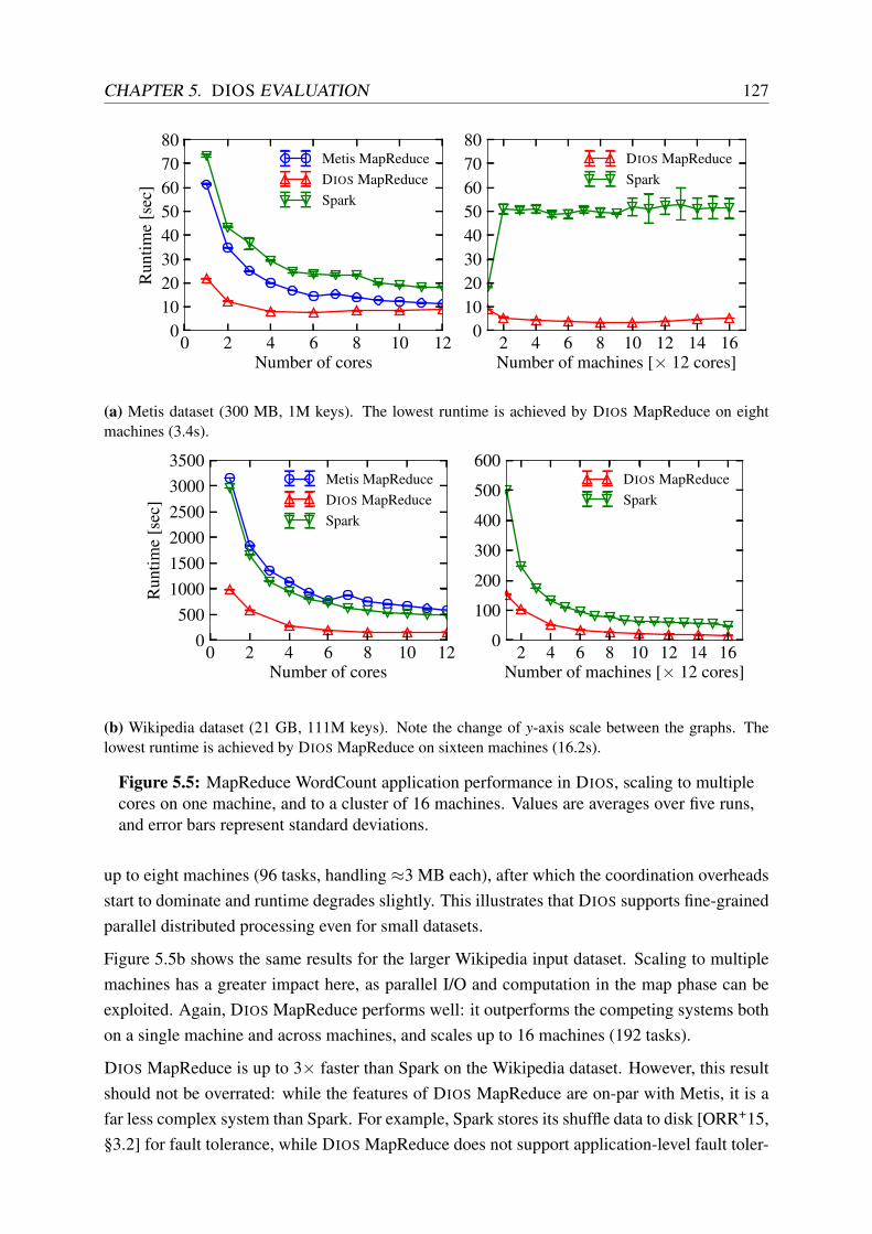
CHAPTER 5. DIOS EVALUATION 127
0 2 4 6 8 10 12Number of cores
01020304050607080
Run
time
[sec
]Metis MapReduceDIOS MapReduceSpark
2 4 6 8 10 12 14 16Number of machines [× 12 cores]
01020304050607080
DIOS MapReduceSpark
(a) Metis dataset (300 MB, 1M keys). The lowest runtime is achieved by DIOS MapReduce on eightmachines (3.4s).
0 2 4 6 8 10 12Number of cores
0500
100015002000250030003500
Run
time
[sec
]
Metis MapReduceDIOS MapReduceSpark
2 4 6 8 10 12 14 16Number of machines [× 12 cores]
0
100
200
300
400
500
600DIOS MapReduceSpark
(b) Wikipedia dataset (21 GB, 111M keys). Note the change of y-axis scale between the graphs. Thelowest runtime is achieved by DIOS MapReduce on sixteen machines (16.2s).
Figure 5.5: MapReduce WordCount application performance in DIOS, scaling to multiplecores on one machine, and to a cluster of 16 machines. Values are averages over five runs,and error bars represent standard deviations.
up to eight machines (96 tasks, handling ≈3 MB each), after which the coordination overheadsstart to dominate and runtime degrades slightly. This illustrates that DIOS supports fine-grainedparallel distributed processing even for small datasets.
Figure 5.5b shows the same results for the larger Wikipedia input dataset. Scaling to multiplemachines has a greater impact here, as parallel I/O and computation in the map phase can beexploited. Again, DIOS MapReduce performs well: it outperforms the competing systems bothon a single machine and across machines, and scales up to 16 machines (192 tasks).
DIOS MapReduce is up to 3× faster than Spark on the Wikipedia dataset. However, this resultshould not be overrated: while the features of DIOS MapReduce are on-par with Metis, it is afar less complex system than Spark. For example, Spark stores its shuffle data to disk [ORR+15,§3.2] for fault tolerance, while DIOS MapReduce does not support application-level fault toler-

128 5.4. SECURITY
ance at the moment. Moreover, Spark runs in a JVM, which necessarily incurs overheads, butoffers a more accessible programming interface to users.
Nevertheless, these experiments demonstrate two points:
1. The decentralised data centre OS model and its DIOS implementation are sufficientlyexpressive to efficiently implement parallel data analytics.
2. DIOS scales to hundreds of parallel tasks, and offers parallel speedups even for fine-grained processing, and matches or outperforms current data processing systems’ runtimefor this workload.
These performance results are an encouraging sign that DIOS may offer efficiency gains for datacentre software. In the following, I consider additional qualitative benefits of using DIOS.
5.4 Security
Security and isolation in the decentralised data centre OS model, and thus in DIOS, rely ondistributed capabilities (§3.4–3.5). In the following, I qualitatively assess the resulting securityproperties of the model by (i) comparing it with alternative isolation techniques used in datacentres, and (ii) sketching a plausible attack that its capability-based protection mitigates.
5.4.1 Comparison with alternative approaches
The primary security goal in a data centre is to isolate independent, possibly mutually distrustingapplications atop shared hardware and software (§3.2.2). Table 5.1 lists existing, commonlydeployed isolation mechanisms and compares their features.
Approaches differ in their overheads (e.g. containers’ lightweight namespaces vs. VMs highmemory overhead), the granularity at which resources can be shared (e.g. capability schemes’fine-grained sharing vs. containers’ and VMs’ coarse-grained shared volumes), and the cus-tomisation opportunities afforded to the infrastructure user (e.g. specialised, custom kernels inunikernels vs. a shared underlying kernel). In general, higher specialisation effort on the infras-tructure user’s part permits tighter compartmentalisation, but restricts sharing.
All of these approaches are single-machine solutions, however: their namespaces and protectiondomains end at the machine boundary. Across machines, they rely on BSD sockets and standardnetwork protocols, which make it difficult to restrict interaction across different compartmentson different machines. Permitting an application to establish network connections is tantamountto enabling it to send any of the data accessible to it to any other task in the data centre, unlessapplication-level authentication and restrictions are implemented. Even if such restrictions arepresent, they are not uniform across different applications (see §2.2.3).

CHAPTER 5. DIOS EVALUATION 129
Approach Overh
ead
Per-tas
k kernel
Isolat
eddist
r. nam
espac
es
Separ
atefiles
ystem
Fine-gra
inedca
pabilit
ies
Resource
shar
ing
Shared machine (processes) none 7 7 7 7 3
Virtual machines (VMs) high 3 7 3 7 7†
Specialised OS/stack (unikernels) medium 3 7 3 7 7†
Kernel namespaces (containers) low 7 7 3 (3) 3
Capability systems (e.g. Capsicum) low 7 7 (3) 3 3
Decentr. data centre OS model (DIOS) low 7 3 3 3 3
Table 5.1: DIOS security properties compare favourably with other inter-task isolationtechniques deployed in data centres. († possible with hypervisor support)
The decentralised data centre OS model, by contrast, supports both isolated distributed names-paces, and fine-grained capabilities using split identifier/namespace capabilities and translucenthandle capabilities. Hence, it supports selective sharing of objects (via delegated handles), andcompartmentalises tasks such that they can only access (and leak data to) a specific, narrow setof objects. DIOS implements this compartmentalisation using names, groups, and references.By contrast with VMs and unikernels, however, DIOS does not run a full OS kernel per task(and hence requires all applications to use the same kernel), and by contrast with containers, itcannot isolate legacy applications from each other.
5.4.2 Case study: the evil MapReduce job
Consider the example of a MapReduce computation, which reads inputs from a distributed filesystem and executes user-provided lambdas for map() and reduce() on the input.
Threat. An “evil” MapReduce job crafted by a nosey developer might not merely access theinputs it is supposed to process (e.g. click logs for ads), but the job may also access otherinformation accessible to the same principal (e.g. email access logs). The evil MapReducejob’s user-provided map() function can “siphon” this additional information into a networkconnection to another, harmless-looking task in another job started by the same principal.
State-of-the-art. Only inbound network access to containers or VMs is typically filtered:outgoing connections can be established to any machine and port in the data centre – in partsince the locations of other tasks are not known ahead of time.
In the Hadoop Distributed File System (HDFS), access control is based on user and group IDsderived from host OS or Kerberos identities [HDFSDocs15]. Other distributed infrastructure

130 5.4. SECURITY
systems see the same limitations, or even do not support access control at all (see §2.2.3.2).This only enforces fairly coarse-grained isolation: any file and directory accessible to the au-thenticated user is accessible to all jobs running as this infrastructure user.
Finally, since the map() and reduce() lambdas are user-specified code, they may have arbi-trary effects, including the invocation of any external binary or library available in the task’sroot file systems.
As a result, the above threat is hard to mitigate in state-of-the-art systems: distributed file systempermissions are insufficiently granular to issue per-job credentials (capabilities); outgoing net-work connections are insufficiently restricted; and the invocation of arbitrary standard binaries(such as nc for network transmission) is possible.
Mitigation in DIOS. If the MapReduce tasks are implemented as pure DIOS binaries, DIOS
restricts them to only access their predefined input and output objects. These input and outputobjects are determined by the infrastructure user, but can be matched against a security policy(e.g. “no job can touch both click logs and end-user emails without approval”) by the clustermanager. The cluster manager creates the DIOS MapReduce job controller task and grants itmembership of groups containing the job input and output objects. The job controller task doesnot run any code provided by the infrastructure user, but resolves the job’s input names, createsintermediate objects and output objects, and delegates references to these objects to the mapperand reducer tasks.
Since the mapper and reducer tasks share no group memberships with the controller task or witheach other, the network communication between distributed file system, mapper and reducertasks is restricted to those streams and intermediate objects permissible under the MapReduceprogramming model. When using DIOS objects, remote I/O is transparent, i.e. the task doesnot know the host or port identities used by the underlying transport objects. Establishing anarbitrary network connection is not possible.7
Finally, if the MapReduce logic needs to invoke a helper binary, it may do so, but it must spawna DIOS task for it. The only executable references available to the MapReduce task are thosewhich were delegated to it by the job controller. Hence, the set of helper binaries is restricted,and the helper subtask inherits the restrictions of the MapReduce task.
5.4.3 Limitations
Like most operating systems, DIOS offers no protection against TCB compromises that enablean attacker to execute arbitrary code inside the TCB (§3.2.2.2). This could happen due to anexploitable kernel or cluster manager bug. However, commonly deployed data centre isolation
7The reader may observe that nothing stops a task from creating its own network stream object and connectingit to a subtask. This is correct – however, the permissible subtasks can be constrained (see next paragraph), orDIOS can deny creation of these object types to untrusted tasks.

CHAPTER 5. DIOS EVALUATION 131
solutions face the same issues: Linux containers do not protect against a kernel compromise,and VMs do not protect against a hypervisor compromise. However, DIOS reduces the attacksurface by offering only a minimal API to pure DIOS tasks (see §4.10.3).
DIOS is also not currently resilient to man-in-the-middle attacks on the data centre interconnect.If an attacker manages to compromise an intermediary (usually a data-link layer switch or arouter), the integrity of RPCs and coordination messages can be compromised. Section 9.1.3discusses possible solutions to this problem.
5.5 Summary
In the preceding sections, I used DIOS to evaluate my decentralised data centre OS model. Iset out a set of requirements for such a novel distributed OS model in Section 3.2, and DIOS
demonstrates that a practical implementation of this model is feasible.
I have demonstrated that DIOS, my implementation of the decentralised distributed data centreOS model, is practical and achieves efficiency and security benefits over the state-of-the-art:
1. The DIOS abstractions are competitive with traditional POSIX abstractions in micro-benchmarks, adding either only minor extra overhead or outperforming them, and enablelow-overhead distributed operations (§5.2).
2. A typical data-intensive application, MapReduce, exhibits competitive performance bothwith state-of-the-art single-machine and distributed implementations when run on DIOS
(§5.3).
3. The decentralised distributed data centre OS model’s resource management abstractionsoffer isolation across machines that improves security over current approaches such aslocal containers (§5.4).
Of course, the performance results presented are impacted by implementation choices in Linux,which are sometimes at odds with the goals of DIOS. In Section 9.1.2, I discuss deeper changesto the Linux kernel that would benefit DIOS.

132 5.5. SUMMARY

Chapter 6
Flexible and scalable scheduling withFirmament
The efficient scheduling of tasks onto compute and I/O resources in the warehouse-scale com-puter is a key challenge for its operating system, and accordingly for DIOS.
In modern data centres, scheduling of work to compute resources happens at two disjoint levels:
1. the cluster scheduler places coarse-grained tasks onto machines, subject to resource avail-ability, and maintains state about machines’ load and liveness; and
2. the kernel CPU scheduler on each node decides on the order in which threads and pro-cesses are executed, and reacts to fine-grained events by moving processes between dif-ferent states, CPU cores, and priority levels.
The time horizons for which these schedulers make their decisions are very different: clusterschedulers’ decisions are in effect for several seconds, minutes, or even hours, while kernelCPU schedulers operate at millisecond timescales.
In this chapter, I describe the Firmament cluster scheduler. Firmament integrates informa-tion from both of the scheduling domains mentioned – cluster-level work placement and local-machine CPU scheduling – to improve overall task placement.
I first offer some background (§6.1), and briefly contrast Firmament with domain-restrictedscheduling approaches in CPU and cluster scheduling. I then introduce the Quincy sched-uler [IPC+09], whose optimisation-based approach Firmament generalises.
Like Quincy, Firmament models the scheduling problem as a minimum-cost, maximum-flowoptimisation over a flow network (§6.2). This approach balances multiple mutually dependentscheduling goals to arrive at a globally optimal schedule according to the costs.
Moreover, Firmament can express many scheduling policies via its flow network using thisinformation – unlike Quincy, which only supports a single policy. I outline how data local-
133

134 6.1. BACKGROUND
ity, fairness, and placement constraints are represented, and point out limitations of the flownetwork approach (§6.3).
After describing how Firmament expresses different policies, I discuss its algorithmic core,the minimum-cost, maximum-flow optimisation. While Firmament primarily targets OLAP-style analytic workloads and long-running services (cf. §2.1.1), it also scales the flow-basedscheduling approach to workloads that include short, transaction processing-style tasks in largedata centres (§6.4).
I then discuss the Firmament implementation, focusing on its architecture, and how it collectsfine-grained information about machine resources and running tasks (§6.5).
Finally, I summarise the chapter (§6.6). In the next chapter, I will I discuss four examplesof customisable cost models for Firmament, define the flow network structure and the costsassigned to the network’s arcs to define different scheduling policies.
6.1 Background
I have already discussed the historic evolution of cluster schedulers and the key goals of recentsystems in Section 2.3. In this section, I show that cluster schedulers can take some usefullessons from an ancestor, the decades-old domain of CPU scheduling (§6.1.1).
I then explain the design of the Quincy scheduler – which Firmament generalises – and theapproach of modelling the scheduling problem as a flow network optimisation (§6.1.2).
6.1.1 Cluster and CPU scheduling
If we view the data centre as a computer, an obvious question is whether we can treat schedulingjust as we would in a very large multi-core machine. There are indeed many commonalities,but also some key differences. Table 6.1 is an attempt at summarising them; I highlight the keydimensions and their impact on Firmament in the following.
Decision scopes: cluster schedulers make decisions over many machines, aggregating hun-dreds of thousands of cores, while CPU schedulers have a myopic view of a single ma-chine’s cores. The latter therefore cannot notice imbalance between machines.
Decision time horizons: while even the fastest cluster schedulers take tens of milliseconds tomake their decisions [OWZ+13], CPU schedulers make fast decisions on context switches,taking on the order of microseconds.
Priority notions: cluster schedulers often derive ad-hoc task priorities based on fairness regimesand application-specific knowledge, while notions of static and dynamic priorities arewell-established in CPU scheduling.

CHAPTER 6. FLEXIBLE AND SCALABLE SCHEDULING WITH FIRMAMENT 135
Cluster schedulers CPU schedulers Quincy FirmamentFeature (§2.3) [IPC+09] (§6.2 et seq.)
Scheduler architecture centralised,distributed
centralised,per-CPU
centralised supportseither
Operating scale 100–10,000machines
hundreds of cores ≤2,500machines
≥10,000machines
Workload types batch, service batch, interactive,real-time
batch batch,service
Task lengthassumption
varies(scheduler-specific)
very short toinfinite
≥seconds short toinfinite
Fairness varying notions varying notions fair share oftasks
fair share oftasks
Constraints soft, hard affinity, pinning 7 soft, hardAdmission control 3, multi-dim. 3 3 3
Preemption common 3 3 3
Explicit priorities common 3 7 3
Dynamic priorities fairly rare 3 3, implicit 3, implicitGlobal view of WSC 3 7 3 3
Application-specificpolicies
some 7, except userlevel schedulers
7 supported
Heterogeneityawareness
rare 7 7 3
Micro-architectureawareness
7 some 7 3
Interferenceawareness
rare rare,heuristic-based
7 3
Data localityawareness
3, common rare 3 3
Deadline support rare rare (RT only) 7 3
Gang scheduling rare 3, common 7 3
Automatic resourcescaling
rare 7 7 7
Table 6.1: Similarities and differences between cluster task scheduling, CPU scheduling,Quincy, and Firmament along different feature dimensions.
Locality and constraints: while process pinning and custom affinities are rarely used in CPUschedulers (mostly in HPC environments), cluster schedulers routinely rely on placementconstraints for locality preferences and improved task performance.
Micro-architecture awareness: typically, cluster schedulers do not take machines’ micro-architecture (e.g. shared caches and NUMA) into account when they make placementdecisions. Some modern SMP CPU schedulers, however, have heuristics that scheduleprocesses to avoid pessimal sharing [Lam13].
Interference awareness: cluster schedulers move work across machines, and some considernegative interference on shared resources [MT13; ZTH+13]; CPU schedulers, by contrast,can only work with the local set of processes, and have little leeway to avoid interference.

136 6.1. BACKGROUND
There are some other minor differences: CPU schedulers can assume shared kernel state inmemory even if they make short-term decisions local to a CPU, and thus have a centralisedcomponent; they more often support gang scheduling; and real-time (RT) schedulers have fine-grained deadline support, while cluster schedulers only sometimes support coarse-grained dead-lines for batch workloads.
Many of these differences, however, boil down to one key difference: in cluster schedulers,application-specific knowledge is commonly available, while CPU schedulers, designed forgeneral-purpose workloads, do not have access to it. Some researchers have recently com-bined application-specific knowledge with CPU scheduling on a single machine (e.g. in Cal-listo [HMM14]); Firmament combines them across machines and uses detailed per-machineand per-process information (such as that used by CPU schedulers) in the cluster scheduler.
At its core, Firmament expresses the scheduling problem as a minimum-cost optimisation overa flow network, which was introduced in Quincy [IPC+09].
6.1.2 The Quincy scheduler
Isard et al. developed the Quincy scheduler [IPC+09] to coordinate Dryad [IBY+07] data pro-cessing clusters. Quincy takes an unusual approach compared to other contemporary sched-ulers: instead of servicing task queues according to a heuristic, it models the scheduling prob-lem as a constraint-based optimisation over a flow network.
Traditional cluster schedulers typically service multiple work queues according to a pre-definedpolicy. This design is similar to the multi-level feedback queue (MLFQ) architecture of a single-machine CPU scheduler [AA14, ch. 8; PS85, pp. 127–9], and enjoys conceptual simplicity andlow scheduling overhead. However, the lack of clear prioritisation and the increasingly complexset of properties and trade-offs that ought to be considered in cluster-wide scheduling make aneffective queue-based abstraction challenging to build.
Consider, for example, the three-way relationship between data locality, fair resource sharing,and scheduling delay (i.e. a task’s wait time in queues): a task may benefit from better locality ifit waits for longer (increasing scheduling delay), or if it preempts a running task (reducing fair-ness). Alternatively, it may run sooner (reducing wait time), but in a worse location (reducinglocality). Heuristically identifying the ideal trade-off over all tasks is difficult.
Furthermore, a queue-based scheduler may choose assignments that satisfy its local heuristics,but which do not correspond to an overall optimum solution.
The key insight behind Quincy’s approach is (Isard et al. [IPC+09, §4]):
[...] that there is a quantifiable cost to every scheduling decision. There is a datatransfer cost incurred by running a task on a particular computer; and there is alsoa cost in wasted time to killing a task that has already started to execute. If we can

CHAPTER 6. FLEXIBLE AND SCALABLE SCHEDULING WITH FIRMAMENT 137
at least approximately express these costs in the same units (for example if we canmake a statement such as “copying 1GB of data across a rack’s local switch coststhe same as killing a vertex that has been executing for 10 seconds”) then we canseek an algorithm to try to minimise the total cost of our scheduling assignments.
Google’s Borg scheduler uses a similar cost-based scoring approach [VPK+15, §3.2]. In Quincy,however, the optimiser considers all jobs, tasks, and machines simultaneously, and thus manydifferent choices and their impact on the cluster. If the costs are set correctly, the resultingschedule is globally optimal – a property that heuristic-driven, queue-based schedulers cannotguarantee.
Quincy maps the scheduling problem to a graph – a flow network – and optimises this graph.Firmament follows the same basic approach, but generalises it: as Table 6.1 shows, Firmamentsupports more scheduling policies than Quincy, adds several advanced features, and utilisesdetailed information traditionally unavailable to cluster schedulers.
6.2 Scheduling as a flow network
At its core, Firmament models also the scheduling problem as an optimisation over a flownetwork (§6.1.2), but generalises the Quincy approach.
This section explains how Firmament constructs the flow network (§6.2.1), and how it assignsarc capacities (§6.2.2) and costs (§6.2.3). In each case, I explain how Firmament’s approachdiffers from Quincy’s. Finally, I introduce equivalence classes, aggregation vertices in Fir-mament’s flow network, which enable generalisation over Quincy and support for additionalscheduling policies (§6.2.4).
6.2.1 Network structure
Firmament, like Quincy, models the scheduling problem as a flow network. It routes flow fromtask vertices to a sink via a path composed of directed arcs, and models task assignments asflow through machine vertices. Each arc in the flow network has an associated cost. Hence,minimising the overall cost of routing flow through this network corresponds to the policy-optimal schedule.1 I discuss the details of common optimisation algorithms for this problem inSection 6.4. In the following, I describe the construction of the flow network itself, and explainhow it expresses the cluster task scheduling problem.
The core component of the flow network is a tree of data centre resources (the resource topol-ogy) that corresponds to the physical real-world data centre topology. For example, machine
1“Policy-optimal” means that the solution is optimal for the given scheduling policy; it does not preclude theexistence other, more optimal scheduling policies.

138 6.2. SCHEDULING AS A FLOW NETWORK
T0,0
T0,1
T0,2
T1,0
T1,1
X
R0
M0
M1
R1
M2
M3
S
U0
U1
Figure 6.1: Example flow network as generated by Firmament for a four-node clusterconsisting of two racks with two machines each. Flow is generated at task vertices (T j,i) androuted to the sink (S) via either machine vertices (Mm) or per-job unscheduled aggregators(U j). The dashed line is a task preference arc (T0,2 prefers M1), while the dotted linecorresponds to T0,1 running on M3.
vertices are usually subordinate to rack vertices, which in turn descend from a common clusteraggregator vertex. Figure 6.1 shows an example flow network for a date centre consisting offour machines (M0–M3) distributed over two racks (R0–R1). The cluster aggregator vertex islabelled as X.2
In addition to vertices for the data centre resources, the flow network also contains a vertex foreach task, independent of whether it is currently scheduled or not. These task vertices are flowsources and each generate one unit of flow (as in Quincy). In the example, two jobs with threeand two tasks are present (T0,0–T0,2 and T1,0–T1,1).
The flow generated by task vertices is eventually drained by a sink vertex (S). To reach the sinkvertex, the flow passes through the resource topology and ultimately reaches a leaf vertex (inthe example, a machine). Each leaf vertex has an arc to the sink vertex.
Since there may be insufficient resources available to execute all runnable tasks, some tasks mayneed to wait in an unscheduled state until resources become available. Since these tasks alsogenerate flow, the network must somehow route their flow to the sink. This role is performedby the per-job unscheduled aggregator vertices (U0–U1). As in Quincy, one such vertex existsfor each job, and all unscheduled aggregators are connected to the sink.
Only the leaf vertices of the resource topology and the unscheduled aggregator vertices are
2The exposition here matches Quincy’s flow network structure, but in Firmament, the specific structure is notfixed: as I show later, the X, Rr, and Mm vertices are merely examples of aggregating equivalence classes.

CHAPTER 6. FLEXIBLE AND SCALABLE SCHEDULING WITH FIRMAMENT 139
T0,0
T0,1
T0,2
T1,0
T1,1
X
R0
M0
M1
R1
M2
M3
S
U0
U1
1
1
1
1
1
1
1
1
1
1
mK
mK
K
K
K
K
K
K
K
K
F0 −E0
F1 −E1
1
1
Figure 6.2: The flow network in Figure 6.1 with example capacities on the arcs.
connected to the sink. This enforces the invariant that every task must either be scheduled orunscheduled, since it can only be in one of the following states:
1. routing its flow through the resource topology, from whence it is routed through a leafvertex where the task is scheduled; or
2. routing its flow directly through a leaf vertex where the task is scheduled; or
3. routing its flow through an unscheduled aggregator, so that the task remains unscheduled.
However, unlike Quincy, Firmament extends the resource topology with additional information.The leaf vertices do not have to be machines: instead, the micro-architectural topology insidethe machines – e.g. NUMA layouts and shared caches – can be automatically added to the flownetwork. I explain this extension in detail in Section 6.5.2.
The quality of scheduling decisions made by optimising a given flow network depends on thecapacities and costs assigned to its arcs. In the following sections, I explain how these arcparameters are determined.
6.2.2 Capacity assignment
Each arc in a flow network has a capacity for flow within an interval [capmin,capmax]. In Fir-mament, as in Quincy, capmin is generally zero, while the value of capmax depends on the typeof vertices connected by the arc and on the cost model.3
3For simplicity, “the capacity” refers to the maximum capacity value in the following.

140 6.2. SCHEDULING AS A FLOW NETWORK
T0,0
T0,1
T0,2
T1,0
T1,1
X
R0
M0
M1
R1
M2
M3
S
U0
U1
task-specific
task-specific
aggre
gator
-
spec
ific
machine-specific
0
0
0
0
0
0
Figure 6.3: The example scheduling flow network in Figure 6.1 with annotations highlight-ing the cost scopes for each arc type, and zero cost terms.
Figure 6.2 illustrates a typical capacity assignment. Outgoing arcs from tasks have unit capacity,and since each machine (M0–M1) can run a maximum of K tasks, the arcs from machines tothe sink have capacity K. Arcs from the cluster aggregator (X) to rack aggregators (R0–R1)have capacity rK for r machines in each rack. Finally, the capacities on the arcs from jobs’unscheduled aggregators (U0–U1) to the sink are set to the difference between the upper boundon the number of tasks to run for job j (Fj) and the lower bound (E j).
Appendix C.2 explains the capacity assignment in more detail and explains why the Fj −E j
capacity on unscheduled aggregators’ arcs to the sink makes sense. Firmament generally assignsthe same capacities as Quincy, but some cost models customise them.
While the arc capacities establish how tasks can route flow through the network and enforcefairness constraints, the costs describe how preferable possible scheduling assignments are.Some costs are general, but others are configurable, and thus allow Firmament to express dif-ferent scheduling policies. I explain the general costs in the next section, and describe how fourFirmament cost models configure others in Chapter 7.
6.2.3 Cost assignment
The cost on an arc expresses how much it costs to schedule any task that can send flow on thisarc on any of the machines reachable through the arc.
To extend Quincy, which assigns ad-hoc costs for its singular policy, I developed the notion ofcost “scopes”, which depend on where an arc is in the flow network (Figure 6.3).

CHAPTER 6. FLEXIBLE AND SCALABLE SCHEDULING WITH FIRMAMENT 141
Parameter Edge Meaningv j
i T j,i → U j Cost of leaving T j,i unscheduled.α
ji T j,i → X Cost of scheduling in any location (usually: worst-case cost).
γj
i,m T j,i → Mm Cost of scheduling or continuing to run on machine Mm.ω – Wait time factor.ν
ji – Total unscheduled time for task.
θj
i – Total running time for task.
Table 6.2: General cost terms in Firmament’s flow network, which exist independently ofthe cost model chosen. Cost models assign specific values to these terms in different ways.
Task-specific arcs can only receive flow from a single task. Their cost expresses factors specificto the nature of the task, e.g. the amount of input data that the task fetches.
Example: the arcs T j,i → X are task-specific arcs.
Aggregator-specific arcs originate at an aggregator and point to another aggregator. Theircost quantifies the cost of any task aggregated by the source aggregator running on anyresource reachable from (≡ aggregated by) the destination aggregator.
Example: the arcs X → Rr are aggregator-specific arcs, since both the cluster aggregator,X, and the rack-level vertices, Rr, constitute aggregators.
Resource-specific arcs point only to a leaf in the resource topology, i.e. a vertex representing amachine or another processing unit directly connected to the sink. Since such an arc canonly route flow to the sink via the resource, it carries a cost specific to running on thisresource (e.g. current existing load).
Example: the arcs Rr → Mm are resource-specific arcs, because the machines’ verticesare leaves in this flow network.
The use of aggregator vertices is beneficial as it reduces the number of arcs required from mul-tiplicative to additive in the number of source and target entities (a property that Firmament’sequivalence classes exploit, as I show in §6.2.4). However, aggregation also reduces the speci-ficity of the costs, as costs specific to an individual entity (task or machine) cannot be expressedon any arcs on the far side of an aggregator.
Some general notions of cost are key to the min-cost flow scheduling approach. I explain themin the following and list them in Table 6.2; the terms here are largely identical to Quincy’s. Thecost models presented in Chapter 7 add additional arcs and cost expressions, and use specificexpressions to compute values for the cost terms in Table 6.2.
1:1 task–resource mappings. If an arc points directly from a task to a schedulable entity(e.g. a machine), the cost associated with the arc is denoted by γ
ji,m for the ith task of job j and
machine m. This cost is specific both to the task (T j,i) and the machine (Mm). All running tasks

142 6.2. SCHEDULING AS A FLOW NETWORK
have a direct arc to the resource they run on, which carries a cost of γj
i,m. In many cost models,γ
ji,m is discounted by a multiple of a task’s current runtime, θ
ji , both to control hysteresis and to
ensure that finite tasks (e.g. batch tasks) eventually finish.
Wildcard mappings. By contrast, if an arc points to the cluster aggregator, then the cost onthe arc expresses the cost of running the task on any subordinate resource. This is denoted byα
ji , and typically expresses a worst-case cost.
Unscheduled mappings. If insufficient resources are available, a task may remain unsched-uled. The cost of this option is denoted by v j
i , and applies to the task’s arc to the unscheduledaggregator vertex for job j (U j). In order to ensure progress and to reduce scheduling delay, thecost on this arc grows as a function of the task’s waiting time: ν
ji denotes the aggregate number
of seconds the task has been waiting in unscheduled state. This encompasses both the initialwait before starting up and any further wait times incurred when the task was preempted. Thevalue is scaled by a constant wait time factor, ω , which increases the cost of keeping the taskswaiting for longer (ω > 1).
Mapping changes due to preemption. Once a task is scheduled on a machine, the schedulermay subsequently decide to preempt it by routing its flow through the unscheduled aggregatorvertex. It may also choose to migrate the task by routing its flow through a different machinevertex; this implies a preemption on the original machine. However, Firmament cost modelscan disallow preemption – in this case, all arcs apart from the 1:1 mapping to the resource atask is scheduled on are removed, thus “pinning” the task.
Many tasks have similar characteristics, and many resources can likewise be treated as similarby the scheduler. Firmament relies on this insight to generalise Quincy to many schedulingpolicies: the following section introduces equivalence classes, which are custom aggregatorsthat enable the construction of higher-level cost models.
6.2.4 Equivalence classes
Unlike Quincy, Firmament classifies both tasks and resources (e.g. machines, CPU cores) intoequivalence classes. An equivalence class contains elements that are expected to behave com-parably, all other factors being equal, and which may thus be treated as fungible for scheduling.This notion is similar to the equivalence classes in alsched [TCG+12].
Equivalence classes therefore allow properties of aggregates to be expressed concisely. For ex-ample, tasks in task equivalence class ct may work particularly well on machines in equivalenceclass cm. Thus, Firmament creates a vertex that all tasks in ct connect to, and connects it to a

CHAPTER 6. FLEXIBLE AND SCALABLE SCHEDULING WITH FIRMAMENT 143
ct cm
T0,0
T0,1
T0,2
Act Acm
M0
M1
cost of running anytask in ct on anymachine in cm
0
0
Figure 6.4: Preference of tasks in ct for machines in cm expressed via equivalence classaggregators (Act and Acm). Dashed lines delineate equivalence classes.
vertex that has arcs to all machines in cm. An arc with a low cost between these vertices nowexpresses the desired property (Figure 6.4).
The use of equivalence class aggregators reduces the number of arcs required to express suchproperties from O(nm) to O(n+m) for a pair of equivalence classes of sizes n and m. Thus,the use of equivalence classes improves overall scheduler scalability. I discuss this further inSections 7.2 and 7.3.
Tasks. A task can have multiple equivalence classes, with different levels of specificity: forexample, all tasks of a job form an equivalence class, all tasks running the same binary aremembers of an equivalence class, and all tasks running the same binary with the same argumentson the same inputs are part of a (narrowly defined) equivalence class.
When using multiple task equivalence classes, the cost on their outgoing arcs should be in-versely proportional to the specificity of the equivalence class. This gives priority to the morespecific equivalence classes, which likely yield better matches as their members’ behaviour isless variable. For example, we might expect all tasks in a job to perform similar work and thushave similar characteristics. However, if the job consists of heterogeneous tasks or the tasks’input data is skewed, a more specific equivalence class (e.g. based on the task binary, arguments,and inputs) has more predictive power.
Typically, the cost model uses a deterministic hash function to combine information such asthe task’s job, its binary and arguments, its inputs, and its parent task, to yield a set of taskequivalence class identifiers.
Resources. Equivalence classes can also aggregate over resources. Most commonly, theyaggregate machines, but other resources can be aggregated similarly. In fact, the cluster aggre-gator (X) and rack aggregators (Rr) in Quincy are implemented as resource equivalence classesin Firmament.
A machine equivalence class is usually a function of the machine’s architecture. Some Firma-ment cost models, for example, generate the machine equivalence class identifier by hashingmachine meta-data, e.g. the machine’s micro-architectural topology (§6.5.2).

144 6.3. SCHEDULING POLICIES
6.3 Scheduling policies
While Quincy supports only a single policy based on data locality and preemption, my workgeneralises its approach to other policies. Firmament achieves this by changing the flow net-work’s structure and its cost and capacity parameters. In this section, I explain how three keypolicy elements – placement constraints, fairness, and gang scheduling – can be modelled, andhow this makes Firmament more expressive than Quincy.
Like most cluster schedulers, Firmament supports placement preferences and both job-level andtask-level constraints. Section 6.3.1 shows how they are encoded in the flow network.
Global fairness across jobs and users is important in multi-tenant environments (cf. §2.3.4),although less crucial in single-authority data centres [SKA+13, §3.4]. In Section 6.3.2, I explainthe notions of fairness that Firmament supports.
When tasks operate in tight synchronisation, they may require gang scheduling in order to avoidwasting resources. I show in Section 6.3.3 that Firmament can support both strict (all tasks) andrelaxed (k-out-of-n tasks) notions of gang scheduling.
Although powerful, the flow network optimisation approach is not without limitations. Sec-tion 6.3.4 discusses policy elements that are challenging to accommodate, specifically: combi-natorial constraints, and global invariants.
6.3.1 Data locality and constraints
Accessing input data locally on a machine, whether in memory or on persistent storage, isoften advantageous to task performance. Data locality is therefore a key part in the originalQuincy scheduling policy [IPC+09, §2.3]. Specifically, locality drives placement preferences inQuincy, as direct preference arcs are added from each task to machines with local data. Some ofFirmament’s cost models described in Chapter 7 have similar notions of placement preferences.
Quincy considers locality preferences only, but Firmament can also express other placementconstraints (§2.3.3). Constraints can be expressed at different granularities by pointing arcs tothe relevant aggregator or resource vertices in the flow network. Different types of constraintsare expressed in different ways:
Soft constraints use the same mechanism as locality preferences: they are expressed by addingpreference arcs with attractive cost values from a task to the relevant location. Most costmodels for Firmament make extensive use of these constraints.
Hard constraints must ensure that no placement violating the constraint is possible. There aretwo ways to achieve this, depending on whether the constraint expresses a positive or anegative affinity:

CHAPTER 6. FLEXIBLE AND SCALABLE SCHEDULING WITH FIRMAMENT 145
1. Affinity constraint: remove a task’s “wildcard” arc to the cluster aggregator vertex,X, and add arcs from the task to permissible locations (or aggregators thereof). Thetask may now only schedule either in a suitable location, or not at all.
2. Anti-affinity constraint: ensure that all paths to locations that violate the constrainthave arcs of cost greater than the maximum cost of leaving the task unscheduledforever.4 This works well if a location needs to be made unavailable to a class oftasks (e.g. batch tasks). Other tasks (e.g. service tasks) can still schedule there viaother arcs or if their unscheduled cost exceeds the anti-affinity cost.
In either case, use of hard constraints on a job breaks any progress guarantee to that job:tasks may never schedule if suitable locations fail to appear, since a wildcard aggregatorsuch as X cannot be used.
Complex constraints involve inter-task dependencies. Since the flow network’s arc costs can-not be dependent on each other, these constraints can only be applied reactively. To usethem, Firmament “drip-feeds” a job’s tasks into the flow network one at a time. Eachtime, the task’s complex constraints are adjusted based on previous decisions. However,the scheduler may decide to invalidate a premise (≡ a prior assignment), which may re-quire re-visiting it in the following round. As a consequence, progress is not guaranteed.
Such reactive, multi-round scheduling increases the scheduling delay for tasks with com-plex constraints. This tends to be the case in current clusters, too: at Google, for example,tasks with complex constraints take up to 10× longer to schedule [SCH+11].
Generally, the higher the out-degree of a constraint’s target vertex, the more likely the constraintis respected and the less it affects the scheduler runtime. This is the case because fine-grainedconstraints introduce additional arcs, and the min-cost flow optimisation runtime is typicallyproportional to the number of arcs in the flow network (see §6.4.2). Equivalence classes (§6.2.4)allow constraints to be applied to entire sets of tasks or resources.
Two common, but not entirely straightforward “constraints” in cluster scheduling are (i) globalfairness guarantees across jobs sharing a cluster (cf. §2.3.4), and (ii) gang-scheduling all tasksin a job. In the next section, I explain how Firmament enforces fairness guarantees using theflow network; Section 6.3.3 looks at gang scheduling.
6.3.2 Fairness
Like Quincy, Firmament supports notions of fairness that partition the total number of runningtasks between users. These notions of fairness are enforced by a combination of admissioncontrol and adapting the maximum and minimum number of running tasks for each job (Fj
and E j for job j, respectively; cf. §6.2.2 and Appendix C.2). The number of tasks allowed
4This only works if there is a ceiling on the growth of ωνj
i , which is true for practical implementations.

146 6.3. SCHEDULING POLICIES
per fair share for job j is A j. By setting E j = A j = Fj, fair shares are strictly enforced; otherconfigurations with E j < A j < Fj give the scheduler more freedom to work towards the fairshare over time and while respecting costs.
In the latter case, Firmament (like Quincy) experiences transient periods of unfairness. Whilemany schedulers rely on task churn to converge to fair shares [GZH+11; HKZ+11; OWZ+13;BEL+14], Quincy and Firmament also preempt tasks. However, unfairness may still occur ifthere are no tasks eligible for preemption.
In the following, I show how Firmament extends Quincy’s original notion of bounded unfair-ness [IPC+09, §1, §2.4, §5.2] to support max-min fair assignments.
Max-min fair policies. The computation of the fair shares (A j) can follow a max-min fairallocation, but the flow network optimisation does not guarantee that preferred resources (e.g.those resources pointed to by a task’s preference arcs) are split in a max-min fair way. As notedby Ghodsi et al. [GZS+13, §8], this can lead to unfairness especially if resources are allocatedin multiple dimensions (e.g. CPU and RAM allocations), as in DRF [GZH+11; BCF+13] andChoosy [GZS+13].
However, Firmament can approximate multi-dimensional max-min fairness. To achieve this,any increase of A j – granting additional tasks to job j – is subject to a condition: extra tasksare only granted if, across all dimensions, the maximum demands of any waiting task in jcan be satisfied without violating max-min fairness. The maximum demands must be usedbecause any waiting task may potentially schedule. Firmament must hence assume that theworst possible task in every dimension is chosen in order to maintain strict max-min fairness.This approximation is more coarse-grained than DRF-style max-min fairness, however: as thethreshold for allowing another task is based on an artificial union of the worst-case demands,Firmament might miss opportunities to schedule tasks without violating the fair share.
Fortunately, heavy-handed enforcement of complex fair sharing policies is not typically re-quired in data centres (unlike in multi-tenant “cloud” environments): anecdotally, Google “[does]not care about fairness” and instead uses quotas and out-of-band policies to steer users’ be-haviour [Wil14, 18:20–19:00]. Indeed, there are use cases in which deliberate unfairness issometimes welcome: one key example is the ability of more important workloads (e.g. servicejobs) to preempt “best effort” jobs even if this violates their fair share of the cluster.
6.3.3 Gang scheduling
Some jobs cannot make progress unless all their tasks are running (for example, a synchronisediterative graph computation), while others can begin processing even as tasks are scheduledincrementally (e.g. a MapReduce job).

CHAPTER 6. FLEXIBLE AND SCALABLE SCHEDULING WITH FIRMAMENT 147
T0,0
T0,n
...GA TAt
max: nmin: k
(a) Relaxed, k-of-n.
T0,0
T0,n
...GA TAt
max: nmin: n
(b) Strict, gang-of-n.
Figure 6.5: Gang scheduling requests are expressed in the flow network by a gang aggre-gator (GA) and an extra arc with appropriate lower and upper bounds on its flow capacity.
Min-cost flow-optimisation schedulers cannot trivially express gang-scheduling constraints be-cause they require dependent costs (cf. §6.3.1): the cost of a feasible assignment is infinite ifeven one of the other tasks in the gang remains unscheduled.
However, the flow network can implement gang scheduling by using arc capacities to force agroup of tasks to schedule. This approach supports both relaxed gang scheduling policies, e.g.one that requires at least k out of n tasks to be placed (as in KMN [VPA+14]), and a strict onewhich requires all tasks in a gang to schedule.
Figure 6.5 shows how this is works, both for relaxed, k-of-n gang scheduling (Figure 6.5a) andstrict, all-n gang scheduling (Figure 6.5b):
1. A new gang aggregator vertex (GA) is added and all tasks in the gang are connected to it.All other outgoing arcs from the tasks are removed.5
2. The gang aggregator is connected to a single aggregator that connects to the prior destina-tions of the tasks’ outgoing arcs. These destinations are typically aggregators themselves(a task equivalence class aggregator, TAt , or the cluster aggregator, X).
3. The lower bound on the capacity of the arc connecting the gang aggregator and the down-stream aggregator is set to 0 < k ≤ n (relaxed) or n (strict), and the upper bound to n.
Since the lower bound forces the new arc to have a flow of at least k, it constrains the acceptablesolutions to the minimum-cost, maximum-flow problem. Namely, only solutions in which atleast k tasks are scheduled are possible. If k = n, this enforces strict gang-scheduling of all ntasks.6
There is one downside to this implementation of gang scheduling: due to the lower boundon capacity, gang-scheduled tasks must be scheduled, independent of their cost. While theynevertheless schedule in the best place available, this placement may come at the expense ofpreempting other tasks whose cost to schedule is lower. Gang-scheduling must therefore beused with a degree of care. It can be limited to high-priority jobs, or gang-scheduled decisionscan be subject to admission control to avoid excessive disruption.
5The removal of other arcs is not strictly required; however, they are guaranteed to receive no flow.6However, if the gang-scheduled tasks exceed the available resources, the solver will fail to find a solution.

148 6.3. SCHEDULING POLICIES
6.3.4 Limitations
Firmament’s global perspective on the scheduling problem allows it to weigh multiple concernsagainst each other, and to flexibly support many scheduling policies. However, the formulationas a minimum-cost, maximum-flow optimisation over a flow network also restricts Firmament’sability to directly express some policies:
Combinatorial constraints. Each unit of flow in the flow network is subject to the same costs,independent of its origin, and each decision to route flow is made independently of otherconcurrent decisions. As a result, dependent costs cannot be expressed using straightfor-ward arcs: costs cannot be conditional. For example, it is not possible to prevent tasksfrom the same job from scheduling on the same machine.
Global invariants. Arc capacities can only enforce bounds on the number of tasks that canschedule through them. If an arc has capacity, any task that can reach it can send flowthrough it, even if the assignment violates a global invariant that is inexpressible via taskcounts. For example, it is not possible to fairly divide aggregate network bandwidth usingarc capacities.
Multi-dimensional capacities. Capacities in the flow network are single-dimensional integersand each unit of flow is atomic. This makes multi-dimensional resource requests (e.g.containing CPU, RAM, and I/O bandwidth requests) difficult to model directly.
All three limitations can, however, be mitigated using two techniques:
1. Reactive multi-round scheduling expresses dependent costs by adapting the costs in theflow network in successive optimisation rounds in response to earlier decisions. Taskswith dependent constraints can only be scheduled one at a time, and must thus be addedto the flow network in sequence (see §6.3.1).
2. Admission control only adds schedulable tasks to the flow network if suitable resourcesare available, and ensures that they can only route flow through suitable resources withsufficient capacity.
Combinatorial constraints (e.g. “no two tasks from this job can share a machine”) can gener-ally be supported via reactive multi-round scheduling, multi-dimensional capacities (e.g. CPU,RAM, disk I/O bandwidth) can be respected via admission control, and global invariants (e.g.fair sharing of rack uplink bandwidth allocations) can typically be expressed via a combinationof the two. Appendix C.4 explains these limitations and the solutions to them in more detail.

CHAPTER 6. FLEXIBLE AND SCALABLE SCHEDULING WITH FIRMAMENT 149
6.4 Scalability
Firmament’s suitability for large data centres depends on the performance of the underlyingmin-cost flow optimisation. The minimum-cost, maximum-flow optimisation problem is a com-putationally intensive problem, and solving it for large graphs requires non-trivial optimisationalgorithms. I explain the problem for reference in Appendix C.1.1; this section assumes basicfamiliarity with the relevant terminology.
In the following, I survey minimum-cost, maximum-flow algorithms and discuss their knowncomplexity bounds (§6.4.1). I then show that, in practice, the scheduling problem sees muchbetter runtimes than the worst-case bounds suggest, but that the algorithm used by Quincy failsto scale to large clusters. However, it turns out that scalability can be much improved by using aseemingly inefficient algorithm in the common case (§6.4.2). Firmament’s min-cost flow solverautomatically uses the fastest algorithm, and incrementally optimises the solution if only minorchanges to the flow network have occurred (§6.4.3).
In Section 8.4, I show that these techniques allow Firmament to scale to very large clusters atsub-second decision times.
6.4.1 Algorithms and solvers
Naïve algorithms for solving the minimum-cost, maximum-flow problem have exponentialcomplexity, but several algorithms with polynomial and strongly polynomial complexity ex-ist. Goldberg [Gol87, p. 41] and Orlin [Orl93] provide concise overviews of the state-of-the-artalgorithms as of the early 1990s. While a detailed discussion of all recent approaches is beyondthe scope of this dissertation, I give a high-level overview of recent algorithms in the following.7
Table 6.3 lists recent key algorithms and their worst-case time complexities. In practice, algo-rithm performance depends both on the flow network structure and the arc costs.
Cycle cancelling. Originally due to Klein [Kle67] and of exponential complexity, cycle can-celling algorithms are the simplest minimum-cost, maximum-flow algorithms. They start froma feasible flow (obtained via a maximum-flow computation), and use the residual network toiteratively cancel negative cost cycles by sending flow along them. Cancelling these cycles re-moves arcs from the residual network; once it is depleted, the optimal solution has been found.A strongly polynomial minimum-mean cycle cancelling algorithm exists [GT89], but it is notcompetitive with other algorithms in practice.
Network simplex. Like cycle cancelling, network simplex is a class of primal algorithms forminimum-cost, maximum-flow. Orlin’s premultiplier network simplex variant [Orl97] achieves
7A more extensive overview can be found in §1.3 and §3.2–3.5 of Adam Gleave’s Part II dissertation, writtenunder my supervision [Gle15].

150 6.4. SCALABILITY
Algorithm Worst-case complexity ReferenceMinimum mean-cost cycles
(Tardos, 1985)O(V 2 polylog(E)) [Tar85]
Relaxation(Bertsekas and Tseng, 1988)
O(E3CU2) [BT88a]
Cycle cancelling(Goldberg and Tarjan, 1989)
O(V E2CU) [GT89]
Successive approximation(Goldberg and Tarjan, 1990)
O(V E log(VC) log(V 2
E )) [GT90]
Premultiplier network simplex(Orlin, 1997)
O(min(V E log(VC),V E2 log(V ))) [Orl97]
Scaling push-relabel(Goldberg, 1997)
O(V E min(log(VC),E log(V )) log(V 2
E )) [Gol97]
Table 6.3: Worst-case time complexities of different algorithms for the minimum-cost,maximum-flow problem. V is the number of vertices, E the number of arcs, U is themaximum capacity, and C the maximum cost.
a polynomial worst-case bound. The MCFZIB network simplex solver [Löb96] is competitivewith cost-scaling algorithms for dense graphs, but falls short on large, sparse graphs similar toFirmament’s flow networks [FM06, pp. 13, 17].
Cost-scaling push-relabel. The cost-scaling family of minimum-cost, maximum-flow algo-rithms is based on work by Goldberg, Kharitonov, and Tarjan [GT90; GK93; Gol97]. Cost-scaling maintains a feasible flow with a bounded deviation from the minimum-cost solution(ε-optimality), and successively refines the solution. Refining involves pushing flow from ver-tices with excess to their neighbours, and relabelling vertices with new prices once no more flowcan be pushed. Appendix C.1.2 explains the algorithm in more detail. In practice, cost-scalingperforms consistently across many different flow networks because its successive refinementavoids exploring partial solutions that turn out to be infeasible.
Relaxation. The relaxation algorithm is based on Lagrangian relaxation [AMO93, ch. 16],and works on the dual version of minimum-cost, maximum-flow. It decouples improvementsin feasibility from cost reductions, and prioritises reducing cost over improving feasibility. Itsworst-case time complexity is cubic in the number of edges, substantially worse than most otheralgorithms. However, it turns out to work well for many Firmament flow networks (§6.4.3).
6.4.2 Scalability of the scheduling problem
The time complexity of the minimum-cost, maximum-flow optimisation is proportional to thesize of the flow network generated by Firmament, which in turn is proportional to both workloadand cluster size.

CHAPTER 6. FLEXIBLE AND SCALABLE SCHEDULING WITH FIRMAMENT 151
Scalability was not a primary concern for Quincy, which targeted clusters of hundreds of ma-chines. The authors evaluated it on a 243-node cluster and found an optimisation runtime of afew milliseconds [IPC+09, §6]. In a simulated 2,500-machine deployment, they found that theoptimisation still completes in “a little over a second” [IPC+09, §6.5]. Industrial data centres,however, often have tens of thousands of machines running thousands of concurrent jobs.
In an experiment similar to the Quincy scale-up simulation, using the cost-scaling cs2 solver,8 Ifound that the solver runtime is super-linearly proportional to the number of arcs in the flow net-work. This is far better than the theoretical worst case of O(V E min(log(VC),E log(V )) log(V 2
E )),but nevertheless poses a noticeable overhead at large scale, especially for workloads of manyshort tasks. Short tasks can occur e.g. when online transaction processing (OLTP) or interactivedata analytics workloads are scheduled. Upwards of 10,000 machines, scheduling with cs2 andusing the Quincy cost model and a Google workload trace [RTG+12] takes over 4 seconds inthe median, and up to 70 seconds in the worst case.
There are several ways in which scalability could, in principle, be improved:
1. Partition the problem by having multiple Firmament coordinators arranged in a tree(§6.5.1), each responsible for scheduling a smaller subset of the overall data centre (e.g.a few racks each). However, a partitioned approach loses the global optimality of place-ments, as each subordinate scheduler can only schedule tasks on a part of the cluster.
2. Use approximate solutions, rather than running the minimum-cost, maximum-flow op-timisation all the way to the end. Since Firmament must routinely work with imperfectdata, it may not be necessary to find the optimal task assignments – an assignment “closeenough” to the optimal solution may be sufficient.
3. Compute an incremental solution by re-using the prior solution and solver state. In alarge data centre, only a small fraction of tasks and machines change state in betweenscheduler iterations, even if they take tens of seconds. Much of the work from a prioriteration can therefore be reused, which might speed up the solver. One appealing prop-erty of this approach is that the number of accumulated changes shrinks as the solvercompletes faster, which in turn reduces the work required in the next iteration.
An investigation into approximate solutions showed that this approach fails to offer meaningfulimprovements for the problems generated by Firmament, since optimality is not reached gradu-ally, but rather by leaps [Gle15, §4.4; GSG+16, §5.1]. However, scalability can indeed be muchimproved by using the relaxation algorithm instead of cost-scaling, and by solving the problemincrementally.
8cs2 was freely available for academic research and evaluation at http://www.igsystems.com untillate 2014; it is now on Github at https://github.com/iveney/cs2.

152 6.4. SCALABILITY
6.4.3 Incremental minimum-cost, maximum-flow optimisation
By default, minimum-cost, maximum-flow solvers expect to be given a complete flow networkand solve it from scratch. When scheduling tasks on a large cluster, however, the number ofchanges to the network between runs of the solver is usually fairly small. Instead of runningthe solver from scratch each time, maintaining state across runs and starting from a previoussolution can accelerate it substantially.
Firmament collects relevant events (e.g. task arrivals, machine failures, etc.) while the solverruns, and applies them to the flow network before running the solver again. The changes to theflow network created by these events reduce to three types of change:
1. Excess is created at a vertex. This happens when a “downstream” vertex, or an arc ona path that previously carried flow, is removed (e.g. due to a machine failure), or whenmore supply is added (e.g. due to the arrival of another task).
2. Capacity is added to an arc. This can either happen because a new leaf resource hasappeared (e.g. a new machine being added), or because a new arc connects two previouslydisjoint vertices (e.g. a new arc between aggregators).
3. An arc’s cost is changed. Typically, this happens because the load on a resource haschanged, a task has waited or run for longer, or the relative goodness of a schedulingassignment has changed due to other assignments. This is the most common change.
Arc capacity can also be reduced without leading to excess (e.g. if an idle machine fails), butthis has no impact on the task assignments unless the cost changes: if the solver previously didnot route flow through the edge, it will not do so after a capacity reduction either.
Firmament supports three ways of optimising the flow network incrementally:
1. An incremental version of Goldberg’s cost-scaling push-relabel algorithm [Gol97] usingthe flowlessly solver.9 This solver first applies the “global price update” heuristic onall vertices to adjust their prices and then re-runs the cost-scaling algorithm. As mostvertices’ prices are already correct or close to correct, the number of “push” and “relabel”operations is greatly reduced.
2. A hybrid approach that combines cost-scaling push-relabel with the relaxation algo-rithm by Bertsekas and Tseng [BT88a]. The relaxation algorithm often outperformscost-scaling in practice on the flow networks generated by Firmament, although it cansuffer from pathological runtime in edge cases that involve highly-contended vertices.flowlessly side-steps these issues by running an instance of incremental cost-scalingalongside relaxation, and by picking the solution of the first algorithm to complete.
9The flowlessly solver was implemented by Ionel Gog and includes both a from-scratch and an incre-mental cost-scaling push-relabel algorithm implementation.

CHAPTER 6. FLEXIBLE AND SCALABLE SCHEDULING WITH FIRMAMENT 153
3. Finally, Firmament also supports a modified version of the relaxation-based RELAXIVsolver [BT88b; BT94], which performs incremental relaxation.10
Incremental cost-scaling yields about a 2× runtime reduction compared to running from scratch.The incremental relaxation achieved higher speedups (up to 14×) in exploratory experiments,but in subsequent work, I have found that most of the speedup is due to the relaxation algorithmbeing a good fit for Firmament’s flow networks and likewise applies to running relaxation fromscratch [GSG+16].
Nevertheless, the combination of relaxation and incremental cost-scaling results in tangiblesolver runtime reductions: in Chapter 8.4, I show that Firmament achieves sub-second schedul-ing latency for a Google-scale data centre and workload.
6.5 Implementation
I implemented Firmament as a cluster manager in approximately 22,000 lines of C++, ofwhich about 7,000 relate to the scheduler. The remainder implements task execution and man-agement, health monitoring and machine management, functionality similar to that found inMesos [HKZ+11] and Borg [VPK+15].
Unlike most previous systems, Firmament can operate both as a centralised or as a distributedscheduler. It uses an optimistically concurrent shared-state approach akin to Omega [SKA+13]to allow multiple distributed schedulers to make parallel decisions. When multiple schedulersare used, they form a delegation hierarchy. I describe the high-level architecture of Firmamentand the possible configurations in Section 6.5.1.
Firmament extracts each machine’s micro-architectural topology and represents it as part of theflow network to permit scheduling decisions at CPU granularity. Section 6.5.2 explains how thetopology information is obtained and used.
In order to make good scheduling decisions at fine granularity, Firmament collects informa-tion about workloads through automatic profiling. Section 6.5.3 describes the methods used toextract the information, and how it is stored and aggregated.
6.5.1 Multi-scheduler architecture
Firmament supports a variety of scheduling setups, including ones with multiple concurrent anddistributed schedulers, and ones in which schedulers form hierarchies.
10The modifications to RELAXIV were made by Adam Gleave as part of his Cambridge Part II individual projectand are described in detail in his dissertation [Gle15, §3.7].
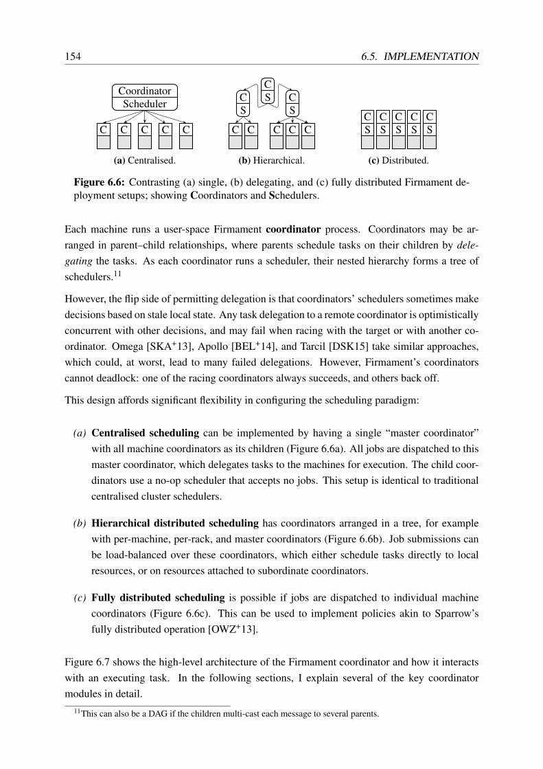
154 6.5. IMPLEMENTATION
SchedulerCoordinator
C C C C C
(a) Centralised.
SC
SCS
C
C C C C C
(b) Hierarchical.
SC
SC
SC
SC
SC
(c) Distributed.
Figure 6.6: Contrasting (a) single, (b) delegating, and (c) fully distributed Firmament de-ployment setups; showing Coordinators and Schedulers.
Each machine runs a user-space Firmament coordinator process. Coordinators may be ar-ranged in parent–child relationships, where parents schedule tasks on their children by dele-gating the tasks. As each coordinator runs a scheduler, their nested hierarchy forms a tree ofschedulers.11
However, the flip side of permitting delegation is that coordinators’ schedulers sometimes makedecisions based on stale local state. Any task delegation to a remote coordinator is optimisticallyconcurrent with other decisions, and may fail when racing with the target or with another co-ordinator. Omega [SKA+13], Apollo [BEL+14], and Tarcil [DSK15] take similar approaches,which could, at worst, lead to many failed delegations. However, Firmament’s coordinatorscannot deadlock: one of the racing coordinators always succeeds, and others back off.
This design affords significant flexibility in configuring the scheduling paradigm:
(a) Centralised scheduling can be implemented by having a single “master coordinator”with all machine coordinators as its children (Figure 6.6a). All jobs are dispatched to thismaster coordinator, which delegates tasks to the machines for execution. The child coor-dinators use a no-op scheduler that accepts no jobs. This setup is identical to traditionalcentralised cluster schedulers.
(b) Hierarchical distributed scheduling has coordinators arranged in a tree, for examplewith per-machine, per-rack, and master coordinators (Figure 6.6b). Job submissions canbe load-balanced over these coordinators, which either schedule tasks directly to localresources, or on resources attached to subordinate coordinators.
(c) Fully distributed scheduling is possible if jobs are dispatched to individual machinecoordinators (Figure 6.6c). This can be used to implement policies akin to Sparrow’sfully distributed operation [OWZ+13].
Figure 6.7 shows the high-level architecture of the Firmament coordinator and how it interactswith an executing task. In the following sections, I explain several of the key coordinatormodules in detail.
11This can also be a DAG if the children multi-cast each message to several parents.

CHAPTER 6. FLEXIBLE AND SCALABLE SCHEDULING WITH FIRMAMENT 155
coordinator
DIOS module RPC module
Executors
Tasktable
Knowl-edgebase
Resourcetopology
Flow network
Min-cost,max-flowsolver
task
Mon
itort
hrea
d
Task
com
puta
tion
Figure 6.7: High-level structure of the Firmament coordinator.
6.5.2 Machine topology extraction
Each coordinator is host to a resource topology, which includes the resource topologies of anychild coordinators. Resources are either (i) schedulable processing units (i.e. CPU threads), or(ii) aggregates that correspond to some degree of sharing between nested elements (e.g. CPUcaches, memory controllers, shared machine-level devices, or shared rack-level uplinks).
On startup, a Firmament coordinator must bootstrap its resource topology. It may find itself ineither of two situations:
1. It has directly attached physical resources that it may schedule. This is necessarily thecase for any (useful) leaf in the tree of coordinators. In this situation, the coordinatordiscovers the resource topology and forwards it alongside a registration message to itsparent coordinator (if any).
2. It is a “virtual” node and has no directly attached machine resources. However, it mayhave (or subsequently discover) children who register their resources with it.
In the former case, information about the machine resources must be extracted from the OS.Firmament uses the portable hwloc library to discover local resources, which in Linux areobtained from sysfs [BCM+10b]. The information returned includes the setup and sizes ofshared CPU caches, as well as NUMA and simultaneous multi-threading (SMT) topologies.
Finally, after the resource discovery is completed – or when a new child coordinator’s regis-tration request is received – the part of the flow network that corresponds to the coordinator’sresource topology is updated to include any new resources. Failures of child coordinators arehandled by removing the appropriate subtree from the local resource topology.
Compared to Quincy, Firmament thus ends up with a larger flow network and represents morefine-grained information about the data centre machines’ resources in it. This explicit represen-tation of machine resources not only allows Firmament to make more fine-grained placement

156 6.5. IMPLEMENTATION
T0,0
T0,1
T0,2
T1,0
T1,1
X
R0
M0
M1
Sock0
Sock1
L3$
L3$
L2$
L2$
L2$
L2$
L1$
L1$
L1$
L1$
L1$
L1$
L1$
L1$
C0
C1
C2
C3
C4
C5
C6
C7
R1
M2
M3
S
U0
U1
Figure 6.8: Example Firmament flow network (cf. Figure 6.1) with added machine topol-ogy for four eight-core machines. Preference arcs and running task arcs are not shown.
decisions, it also offers a way of representing heterogeneity in machine types and architecturesto the scheduler.
Figure 6.8 shows the example flow network from Figure 6.1 extended with the topology infor-mation extracted by Firmament. This extra detail, however, does not come for free: it increasesthe number of nodes and edges in the flow network and necessitates judicious aggregation ofsubtrees via equivalence classes (§6.2.4) in order to restrict the number of arcs from tasks toresources.
6.5.3 Task profiling
The Firmament coordinator on each machine in the cluster is responsible for running, monitor-ing, and profiling tasks. In particular, using the mechanisms described in the previous section,it acquires statistical information about tasks’ performance and resource needs. This informa-tion is stored in the knowledge base coordinator module, where cost models may access it toimprove future decisions.
Firmament acquires this information from two principal sources:
1. Operating system resource accounting information, exposed, for example, via procfs
in Linux. This includes information about the aggregate RAM and CPU time consumed,yield and preemption counts, and other information that accrues as a result of OS choices.

CHAPTER 6. FLEXIBLE AND SCALABLE SCHEDULING WITH FIRMAMENT 157
Metric Type SourceVirtual memory size sampled procfsReal memory size sampled procfsTime runnable and scheduled sampled procfsTime runnable and waiting sampled procfsTotal runtime aggregate timerTotal cycles aggregate HW counterTotal instructions aggregate HW counterLLC references aggregate HW counterLLC misses aggregate HW counterCycles per instruction (CPI) aggregate calculatedMemory accesses per instruction (MAI) aggregate calculatedInstructions per memory access (IPMA) aggregate calculated
Table 6.4: Metrics tracked by the Firmament coordinator for each task running on the localmachine, in addition to used and available resources.
2. CPU hardware performance counters, which track low-level and micro-architectural events.This includes metrics such as the last-level cache miss count, the frequency of stalls dueto DRAM access or I/O, and the number of instructions per memory access.
Table 6.4 lists the precise set of metrics tracked in the current Firmament implementation. Met-rics are measured either by continuous sampling during task execution, or by retrieving anaggregate summary when a task completes. The latter approach is useful to determine aggre-gate metrics over the task’s lifetime (e.g. its total CPU migration count), but works less well forlong-running service tasks, since it may take a very long time until the metrics are reported forsuch tasks. Either collection strategy, however, only adds negligible overhead to tasks’ runtime.
All information collected is stored in the coordinator’s knowledge base and forwarded to othercoordinators as appropriate. Subordinate coordinators forward new information to their parentcoordinator, although they may aggregate it for a while in order to send a batched update.
The collection of such information is not entirely novel: CPU performance counter informationhas been used for cluster scheduling before. For example, CPI2 at Google implements reactivetask migration based on sampling the cycle and instruction counters. Using the cycles-per-instruction (CPI) metric, CPI2 detects negative interference between co-located tasks [ZTH+13].Likewise, Mars et al. have used performance counter information on the frequency of last-levelcache (LLC) misses to avoid interference on a single machine [MVH+10].
Firmament similarly collects performance counter information, but also aggregates it acrossmany machines. This allows Firmament to build a profile specific to each task, its combinationwith a machine type, and the set of co-located tasks. As many tasks often perform similarwork in parallel, Firmament uses its equivalence classes to combine their performance metrics.Since the cost model controls which equivalence classes a task is part of, metrics can be flexiblyaggregated along different dimensions in this way. Based on the collective performance metricsreceived for all tasks in an equivalence class, Firmament rapidly establishes an accurate profile.

158 6.6. SUMMARY
6.6 Summary
In this chapter, I contrasted cluster scheduling for data centres with single machine CPU schedul-ing, and illustrated how my Firmament cluster scheduler draws on both (§6.1).
Firmament is unusual because it maps the scheduling problem to a minimum-cost, maximumflow optimisation – an approach only taken in one prior system, Quincy (§6.2). Firmamentgeneralises the flow network optimisation approach by customising network structure, andhence expresses many scheduling policies (§6.3). Moreover, Firmament substantially improvesthe scalability of the flow network optimisation approach to scheduling: it relies on multipleminimum-cost, maximum-flow algorithms, and applies optimisations to improve their perfor-mance (§6.4).
Finally, I described the Firmament architecture, and how it obtains the fine-grained profilinginformation and makes it available to scheduling policies (§6.5).
In the following, Chapter 7 demonstrates Firmament’s flexibility via four different cost models,covering a wide range of policies that Firmament can express.
In Chapter 8, I evaluate Firmament using both real clusters and a trace from a Google datacentre, and find that it compares favourably to other systems and scales well.
Chapter 7
Firmament case studies
Firmament supports a standardised interface for custom, configurable cost models. A cost modeldescribes a scheduling policy by assigning concrete cost values to the different arcs in the flownetwork (see Appendix C.5 for the cost model API).
In the following, I describe three different cost models that I have implemented for Firmament.I first briefly introduce the original Quincy cost model (§7.1; details in Appendix C.3). I thenexplore the power of Firmament’s customisable cost models via three case studies:
1. a cost model based on the Whare-Map [MT13] system for exploiting the benefits ofresource heterogeneity and avoiding co-location interference (§7.2);
2. the coordinated co-location (CoCo) cost model, which integrates the distributed clusterscheduler and local CPU affinity by scheduling tasks directly to hardware threads (§7.3);and
3. the Green cost model, an energy-aware scheduling approach which optimises task place-ment in a highly heterogeneous cluster with respect to performance constraints and livepower monitoring data (§7.4).
In Section 7.5, I summarise and contrast the properties of the four cost models described.
Chapter 8 will evaluate these cost models for a range of workloads and clusters. Other costmodels are, of course, also conceivable, and Section 8.3 will sketch how existing schedulers’policies can be translated into Firmament cost models.
7.1 Quincy cost model
Quincy does not support customisable cost models, but instead assigns costs that express aspecific trade-off between data locality, task wait time, and wasted work due to preemption ofrunning tasks.
159

160 7.2. WHARE-MAP COST MODEL
T0,0
T0,1
T0,2
T1,0
T1,1
X
R0
M0
M1
R1
M2
M3
S
U0
U1
α 00
α 01
α02
α10
α11
v00
v01
v0 2
v 10
v11
0
0
0
0
0
0
0
0
0
0
0
0
γ ′10,M3
γ02,M1
Figure 7.1: The example flow network in Figure 6.1 with costs according to the Quincycost model added to the arcs. The capacities are assigned as in Figure 6.2.
Figure 7.1 shows the flow network structure and cost terms in Quincy. The cost to the unsched-uled aggregator, v j
i is proportional to the task’s wait time, while the cost to the unscheduledaggregator, α
ji , is set to a cost proportional to the data transfer required at the worst possible
locality in the cluster. Additionally, a preference arc to a rack aggregator Rl has cost ρj
i,l pro-portional to the worst-case data transfer within the rack, and an arc to a machine Mm has costγ
ji,m proportional to the data transfer required when scheduling on this machine.
In Appendix C.3, I explain the exact cost terms and how their values are determined. Firmamentsimply models the cluster aggregator (X) and the rack aggregators (Rl) as resource equivalenceclasses, and there are no task equivalence classes in the Quincy cost model.
7.2 Whare-Map cost model
The Whare-Map system by Mars and Tang avoids negative interference and exploits machineheterogeneity in WSCs [MT13].1 In essence, Whare-Map builds a matrix of performance scoresfor each combination of a task, machine type and potentially interfering tasks. It then applies astochastic hill-climbing approach to find good assignments.
Some of the high-level goals for Whare-Map and Firmament are similar: both try to avoid co-location interference, and both aim to improve utilisation by using heterogeneous data centreresources as efficiently as possible. In the following, I demonstrate that Firmament can expressall of Whare-Map’s scoring policies via a cost model.
1The same work was previously described in Mars’s 2012 PhD thesis under the name SmartyMap [Mar12].

CHAPTER 7. FIRMAMENT CASE STUDIES 161
Whare-Map bases its notion of cost on performance scores attributed to a task in differentenvironments. The scoring metric used by Mars and Tang is instructions-per-second (IPS),measured by hardware performance counters [MT13, §5.3].
Unlike other approaches that require a priori profiling (e.g. Paragon [DK13] and Quasar [DK14]),Whare-Map can build its scoring matrix incrementally as tasks run and information is obtained.This yields no benefit for tasks that only run once, but can be useful in data centre environmentswhere the majority of work is recurring [RTM+10; ZTH+13].
Whare-Map’s scoring information for each task type can be maintained at different levels ofgranularity. In Firmament, I use task and machine equivalence classes (§6.2.4) to aggregateinformation for similar tasks and machines.
Whare-Map has four scoring policies:
1. Whare-C, which is based on co-location interference only, but ignorant to heterogeneousmachines;
2. Whare-Cs, which takes into account co-location interference for each machine type;
3. Whare-M, which uses machine type affinities, but does not consider co-location interfer-ence at all; and
4. Whare-MCs, which takes all of the above into account (machine-specific co-locationinterference and machine type affinity).
Mars and Tang found Whare-M and Whare-MCs to be most effective for their workloads, and Ionly consider these variants in the following. However, they subsume Whare-C and Whare-Csas degenerate cases of Whare-MCs.
7.2.1 Flow network structure
Figure 7.2 shows an example Firmament flow network for both Whare-Map cost models.
For Whare-M, the scoring function maps each task to its affinity for different machine types.This is implemented by linking each task to a set of machine aggregator vertices in the flownetwork, each of which represents one machine type (MAcm for machine type cm in Figure 7.2).
The aggregator vertices are in turn connected to all machines of the type represented. For mmachines, n machine types, and t tasks, this approach requires n vertices and nt +m arcs. Thenumber of distinct machine types in the cluster, n, is usually on the order of a few dozen (cf.§2.1.2). Thus, t m n, making this solution preferable over a naïve approach of each taskhaving an arc to each machine, which requires mt arcs but adds no more information.
To further reduce the number of arcs, it makes sense to add aggregators for tasks of the sameequivalence class (TAct for equivalence class ct). For u different task equivalence classes, using

162 7.2. WHARE-MAP COST MODEL
T0,0
T0,1
T0,2
T1,0
T1,1
X
M0
M1
M2
...
Mm
S
U
TAct MAcm
v00
v01
v0 2
v1 0v1 1
Ψ(ct ,cm)
γ02,M
0
γ 10,M2
Ξ(c t,L
m,cm)
Figure 7.2: Firmament flow network with the Whare-Map cost models. Blue arcs are onlypresent in Whare-MCs, while black ones are in both Whare-M and Whare-MCs. Red, dot-ted arcs correspond to already running tasks. Note that Whare-Map has no rack aggregatorsand this graph uses a single unscheduled aggregator (U), rather than per-job ones.
Parameter Edge Meaningv j
i T j,i → U j Cost of leaving T j,i unscheduled.α
ji T j,i → X Cost of scheduling in the worst possible location.
γj
i,m T j,i → Mm Cost of continuing to run on machine Mm.Ψ(ct ,cm) TAct → MAcm Cost of running task of type ct on a machine of type cm.
Ξ(ct ,Lm,cm) TAct → Mm Cost of running task of type ct with co-located tasks in Lm.
Table 7.1: Cost parameters in the Whare-Map cost models and their roles.
aggregators requires u+n vertices and O(t+un+m) arcs, with t m u ≥ n. Since t+un nt, this approach scales better than using machine-type aggregators only.
I denote the score for a task category ct on a machine of type cm by the function Ψ(ct ,cm). Inthe flow network, Ψ(ct ,cm) is associated with an arc between a task aggregator (TAct ) and amachine type aggregator (MAcm), as shown in Figure 7.2.
Since Whare-M relies only on information about tasks’ performance on different machine types,it requires only limited profiling information. However, the collected profiling information foreach machine type m can be noisy, since tasks’ performance variation due to the machine typemay be diluted by co-location interference from other tasks.2
The Whare-MCs policy takes interference from co-located tasks into account. It extends thescoring function with a component dependent on the tasks that already run on a candidate ma-
2Profiling tasks in isolation is impractical as it reduces utilisation; biasing the score in favour of those fromotherwise idle environments might work, but such environments are rare in practice.

CHAPTER 7. FIRMAMENT CASE STUDIES 163
chine. I refer to the set of equivalence classes of co-located tasks as Lm, and express the co-location score for a task in equivalence class ct via the function Ξ(ct ,Lm,cm).
This extension requires additional arcs from TAct to individual machines, since the co-locationinterference is a property of the workload mix scheduled on a specific machine. I therefore addarcs from each task aggregator to machines with preferable co-location conditions. The numberof outgoing arcs from task aggregator TAct is equal to the minimum of the number of incomingarcs into TAct and the number of machines with suitable resources.
The machine type aggregators and the arcs connecting the task type aggregators to them (atΨ(ct ,cm) cost) are still present in Whare-MCs. However, since the profiling data for Ψ(ct ,cm)
is less specific as it averages over all profiled co-locations, the lowest cost values of Ξ(ct ,Lm,cm)
are likely better, and the highest values worse, than Ψ(ct ,cm):
minLm
(Ξ(ct ,Lm,cm))≤ Ψ(ct ,cm)≤ maxLm
(Ξ(ct ,Lm,cm))
As a result, it is more attractive for tasks to schedule via the co-location-aware arcs than viathose pointing to the machine type aggregators. If insufficiently many good co-location optionsare available, however, tasks still schedule on the best machine type available in preference toscheduling via the cluster aggregator vertex, X.
7.2.2 Cost assignment
Since the flow optimisation requires costs to increase as placements become less desirable, theIPS metric used in Whare-Map, in which greater values are better, must be inverted. Conse-quently, I convert IPS to seconds-per-instruction by dividing the task runtime by the instructioncount obtained from performance counters (cf. §6.5.3). As the available solvers require integralcosts, I further normalise this metric to picoseconds-per-instruction (psPI).3
I have already explained the definitions of Ψ(ct ,cm) and Ξ(ct ,Lm,cm) and the arcs on whichthey are applied. The costs assigned to other arcs are similar to those in the Quincy cost model,albeit re-written in terms of the Whare-Map scores instead of data transfer costs:
• v ji is the cost of leaving the ith task in job j unscheduled. It is proportional to the wait
time νj
i , and lower-bounded by the average Whare-Map score, with T j,i ∈ ct :
v ji =
max(ν ji ,Ψ(ct ,cm)) for Whare-M
max(ν ji ,Ξ(ct ,Lm,cm)) for Whare-MCs
• αj
i is the cost of scheduling via the cluster aggregator and is set to the cost of schedulingin the worst possible location. In Whare-Map, this is the machine equivalence class least
3For modern gigahertz-clocked CPUs, this value ranges from approximately 250 (IPC = 1, e.g. simple integerarithmetic on a 4 GHz CPU) to 100,000 (IPC = 1⁄400, e.g. remote DRAM-bound work).

164 7.3. COORDINATED CO-LOCATION COST MODEL
suited towards task T j,i (Whare-M) or, the machine where the task will experience theworst possible interference (Whare-MCs). In other words, for T j,i ∈ ct :
αj
i =
maxcm(Ψ(ct ,cm)) for Whare-M
maxLm,cm(Ξ(ct ,Lm,cm),Ψ(ct ,cm)) for Whare-MCs
• γj
i is the cost of running T j,i on a particular machine, or continuing to run there if alreadyscheduled. As in Quincy, the cost of continuing to run in a location is discounted by thetotal cumulative runtime of T j,i.
7.2.3 Summary
The Whare-Map cost models implement the policies of the published system [MT13], withone key difference: instead of using the approximate stochastic hill-climbing approach, theFirmament version is based on an exact minimum-cost flow optimisation. However, severalimprovements to the cost model are conceivable; I summarise them below.
Model machine load. The co-location-aware arcs (TAcm → Mm) implicitly reflect the load ontheir target machines (since load-proportional interference increases the cost), but the arcsfrom machine type aggregators to machines (MAcm → Mm) have a zero cost.
In order to bias scheduling towards machines with lower load, the arcs from machine typeaggregators to machines could be assigned costs proportional to the machines’ load.
Express co-location at CPU granularity. Whare-Map considers co-location sets at machinegranularity (Lm). However, Firmament routinely extracts the micro-architectural topologyof each machine (§6.5.2).
One could imagine extending the Whare-Map cost model described to manage CPUsrather than machines: instead of scoring co-location set Lm in Ξ(ct ,Lm,cm), the scorewould be specific to the tasks running on CPU cores that share caches with the target.
My next Firmament cost model, the coordinated co-location model, incorporates these ideas ina more advanced cost model that also supports resource reservations.
7.3 Coordinated co-location (CoCo) cost model
The Whare-Map cost model described in the previous section addresses co-location interferenceand machine heterogeneity. However, it comes with a number of limitations:
1. It does not provide for scheduling dimensions other than machine type affinity and co-location interference.

CHAPTER 7. FIRMAMENT CASE STUDIES 165
2. It only supports a very coarse-grained, machine-level notion of co-location interference.
3. It does not model tasks’ resource demands and the available resources on machines; ma-chine load is only implicitly considered as part of the co-location scores.
4. It does not afford the flexibility to assign a higher weight to some scheduling dimensionsthan to others.
To address these limitations, I developed the Coordinated Co-location (CoCo) cost model forFirmament.
The key insight in the CoCo cost model is that costs can be modelled as multi-dimensional costvectors, and that this, in combination with task equivalence class aggregators (§6.2.4), offers anefficient way of expressing tasks’ multi-dimensional resource requirements.
In summary, the CoCo cost model offers the following properties:
1. Strict priorities: higher priority tasks are always scheduled in preference to lower prior-ity ones.
2. Strict resource fit: tasks only schedule on machines that have sufficient available re-sources to accommodate them.
3. Balanced load: tasks preferentially schedule on lower-loaded machines, i.e. a task doesnot schedule on a highly-loaded machine when an otherwise equivalent lower-loaded oneis available.
4. Low average wait time: the longer a task waits to schedule, the more likely it is to beassigned a suboptimal placement instead of waiting further.
CoCo achieves these properties by a combination of admission control, smart cost assignment,and efficient updates to the flow network.
7.3.1 Admission control
To meet the strict resource fit property, CoCo must match tasks to resources such that no taskcan be scheduled on a machine with insufficient available resources. This is more complex thanit might seem.
First of all, if a task does not fit on all machines, we must remove the arc to the cluster ag-gregator, X. A naïve approach would instead add arcs to all suitable machines, but this requiresO(t×m) task-specific arcs. Consider the case of a task that fits on all machines but one: it wouldend up with m−1 preference arcs. Capping the number of preference arcs per task would solvethis, but loses optimality since the missing arcs restrict the possible solutions.

166 7.3. COORDINATED CO-LOCATION COST MODEL
T0,0
T0,1
T0,2
T1,0
T1,1
X
R0
M0
M1
Sock0
Sock1
L3$
L3$
L2$
L2$
L2$
L2$
L1$
L1$
L1$
L1$
L1$
L1$
L1$
L1$
C0
C1
C2
C3
C4
C5
C6
C7
R1
M2
M3
S
U0
U1
TAc0
TAc1
Figure 7.3: Firmament flow network for the CoCo cost model. Each job’s tasks have oneequivalence class, represented by task aggregator TA j. Dotted arcs indicate tasks alreadyrunning (T0,2 and T1,0), while dashed arcs point to maximally aggregated subtrees of theresource topology where tasks fit: job 0’s tasks fit under socket 0 on M0 and on M1, andjob 1’s tasks fit anywhere in rack R1 and on M1.
Instead, I change the structure of the flow network to accommodate CoCo (see Figure 7.3). Eachtask receives arcs to its task equivalence class aggregators (e.g. TAc0 and TAc1). From these ag-gregators, CoCo adds outgoing arcs to maximally aggregated subtrees of the resource topology,which represent locations in which the tasks in the equivalence class definitely fit. Several suchsubtrees may exist, and each may include multiple machines – consider, for example, a rack inwhich a task fits on all machines (e.g. TAc1 on R1).
For small tasks that fit in many places, these aggregates are large and require few arcs, whilelarge and “picky” tasks receive a small set of highly specific arcs. In addition, CoCo caps thenumber of outgoing arcs at each task aggregator to the n cheapest ones, where n is the numberof incoming task arcs: no more than n tasks can schedule via this aggregator anyway, so thisdoes not compromise optimality.
Efficient admission control. The above approach has an attractive invariant: no path froma task to the sink crosses any machine where the task is unable to fit. To maintain the correctset of arcs, however, the scheduler must on each iteration (and for each task equivalence class)reconsider all machines whose resource load has changed. This computation can be simplifiedby tracking some state in the flow network: for each resource vertex, CoCo maintains current

CHAPTER 7. FIRMAMENT CASE STUDIES 167
1 vector<ResourceID_t>* CocoCostModel::GetMaximallyAggregatedSubtrees(2 EquivClass_t task_ec, const ResourceTopologyNode* start_res) 3 vector<ResourceID_t>* subtree_heads = new vector<ResourceID_t>();4 queue<const ResourceTopologyNode*> to_visit;5 to_visit.push(start_res);6
7 // Breadth-first traversal with early termination conditions8 while (!to_visit.empty()) 9 ResourceTopologyNode* res_node = to_visit.front();
10 to_visit.pop();11 // Check task fit12 TaskFitIndication_t task_fit =13 TaskFitsUnderResourceAggregate(task_ec, res_node);14 if (task_fit == TASK_ALWAYS_FITS) 15 // We fit under all subordinate resources, so put an arc here and16 // stop exploring the subtree.17 subtree_heads->push_back(res_node->uuid());18 continue;19 else if (task_fit == TASK_NEVER_FITS) 20 // We don’t fit into *any* subordinate resources, so give up21 // on this subtree.22 continue;23 24 // We fit at least in some dimensions, so we may have suitable25 // resources here -- let’s continue exploring the subtree.26 for (auto rtnd_iter = res_node->children().pointer_begin();27 rtnd_iter != res_node->children().pointer_end();28 ++rtnd_iter) 29 to_visit.push(*rtnd_iter);30 31 32 return subtree_heads;33
Listing 7.1: Simplified excerpt of the CoCo resource fitting code: a breadth-first traver-sal of the resource topology yields maximally aggregated subtrees under which tasks inequivalence class task_ec definitely fit.
minimum and maximum available resources across its children. This is implemented as a simplebreadth-first traversal in Firmament (see Listing 7.1), which discovers suitable subtrees in worst-case C×O(N) for C task equivalence classes and N leaves in the flow network.
An even faster approach would use a pre-constructed two-dimensional segment tree for worst-case C×O(log2 N) traversal time; constructing the segment tree has a one-off cost of O(N logN),and each update of a machine in response to changes costs at most O(log2 N).
Resource overcommit. Whether a task from an equivalence class “fits” under a resource ag-gregate – i.e., the result of TaskFitsUnderResourceAggregate() in Listing 7.1 – depends

168 7.3. COORDINATED CO-LOCATION COST MODEL
on three factors: (i) the resource request for tasks in this equivalence class; (ii) the current re-served resources and actual load of the resources in the aggregate; and (iii) the workload typerepresented by the task equivalence class:
• For service jobs, an arc is added unless the task’s resource request exceeds the reservedmachine resources in any dimension. This is very conservative: actual resource usage istypically far lower than the reservation – e.g. by 30–40% at Google [RTG+12, §5.1].
• For batch jobs, an arc is added unless the task’s resource request exceeds the used ma-chine resources in any dimension. This allows spare resources on machines to be usedby best-effort batch tasks. However, if the service tasks’ usage increases, batch tasks arekilled to free up resources.
If a task fits under an aggregate, an arc between TAct and the resource aggregate is added, andits cost is set as described in the following.
7.3.2 Cost assignment
Each cost in CoCo is expressed internally as an eight-dimensional vector:
a(v,w) = A =
PriorityCPU cost
Memory costNetwork costDisk I/O cost
Machine type costInterference costData locality cost
The vectors are flattened to an integral cost (required by the solver) via a weighted inner product,i.e. a(v,w) = w0A0 + · · ·+w7A7.
The cost values in the different dimensions depend on the type of arc that the cost vector isassociated with:
1. On task-specific arcs (any outgoing arc from a task vertex, i.e. T j,i → ∗), the prioritydimension is set to the task’s priority, while the CPU, memory, network, and I/O dimen-sions indicate the task’s resource request, i.e. the resources it needs to run. The remainingdimensions (machine type, interference, and data locality cost) are set to zero.
2. On resource-specific arcs, CPU, memory, network, and I/O costs are set to an indicationof the resource’s load in each dimension. For higher load, the cost increases. Machinetype and interference costs are set according to the resource’s machine type and any ex-isting co-running tasks. Priority and data locality costs are set to zero.
CHAPTER 7. FIRMAMENT CASE STUDIES 169
3. On an unscheduled arc (T j,i → U j), the costs in the resource capacity dimensions are setto the maximum value, while the cost in the interference and machine type dimension isset to one.
The values in each dimension are normalised into the range [0,Ω), where Ω is a fixed maximumcost value. For resource requests and load, the value is first normalised to the largest quantityof the resource available in any machine, and then multiplied by Ω.
Co-location interference. Expressing the cost of co-location interference requires a differentapproach to resource requirements, since interference cannot be quantified as a fraction of a totalcapacity. Moreover, the interference experienced by a task increases as a function of sharingresources with more (or more aggressive) neighbours.
CoCo relies on interference classes to model the interaction of tasks when sharing resources.In the Firmament prototype, tasks are currently manually classified by the user, but automaticclassification is possible.4
Each leaf of the resource topology supplies a penalty score for each interference class. A lowpenalty score implies a strong affinity for a neighbour of that class. For example, “devil” tasks(strongly interfering) have a low affinity – and a high penalty score – for interference-sensitiveneighbours (“rabbits” and “sheep”), but a medium affinity for further “devils”.
Each leaf’s penalty score is used as its resource-specific cost, and is propagated upwards throughthe resource topology in two ways:
1. Each vertex stores the normalised cumulative penalty score of its children for each class.This allows CoCo to propagate class-specific interference scores for resource aggregates;as a result, different task equivalence classes see different interference scores when theyadd arcs to an aggregate.
2. Each arc within the resource topology carries an integral cost proportional the penaltyscores of its children, with the impact of an individual leaf’s score decaying as it propa-gates upwards. The cost for an arc that does not directly connect a leaf is given by:
cost(u,w) = et−i
t ×∑v∈children(w) cost(w,v)
num. children of w,
where i is the number of idle leaf resources below the current one, and t is the total numberof subordinate resources. The super-linear e
t−it scale factor ensures that dense clusters of
idle resources are preferred to sparse collections of idle resources.
The arc cost enables CoCo to steer an incoming task’s flow towards the least interferinglocation within a resource aggregate.
4For example, the “animal” taxonomy proposed by Xie and Loh for cache partitioning [XL08] can be used toautomatically classify tasks based on the profiling data collected (§6.5.3).

170 7.3. COORDINATED CO-LOCATION COST MODEL
The cost specific to the task equivalence class (on the TAct → resource aggregate arc) empha-sises the interference that a task must expect within an aggregate. The costs on arcs withinthe resource aggregate, by contrast, are proportional to load and interference below each re-source. Their combination has a useful effect: the cheapest path through a resource aggregatecorresponds to the most preferable task placement.
Priorities. The priority dimension in the cost vector is inversely proportional to a task’s prior-ity: the lower the value, the higher the priority of the task. In order to maintain strict priorities,the cost model must ensure that the priority dimension always dominates. This is achievedby scaling the priority component by d ×Ω, where d is the number of dimensions (eight) andadding this value to the cost when flattening a cost vector.
The CoCo cost model supports priority preemption, which occurs if a task of higher priority (i.e.lower cost in the priority dimension) displaces another task with lower priority. However, ser-vice jobs cannot be preempted by batch jobs, since batch job’s lower priority always dominatestheir cost.
7.3.3 Dynamic flow network changes
Firmament’s flow network optimisation approach allows many scheduling assignments to bemade at the same time. This is problematic for CoCo, because the solver may place tasks insuch a way that their resource requirements conflict. For example, M1 in Figure 7.3 may havefour idle CPU cores, but may only have sufficient I/O capacity for either a task from TAc0 ora task from TAc1 . With two incoming arcs, however, nothing stops both T0,0 and T1,1 fromscheduling there.
To prevent this situation from arising, CoCo introduces two restrictions:
1. Selective arc creation: arcs to resource aggregates are only added until the cumulativeresource requirements for the possible incoming tasks exceed the available resource ca-pacity.
2. Unit capacities: the capacity on all arcs to resource aggregates, within the resource topol-ogy and from its leaves to the sink, is set to one.5
As a result, tasks schedule in “waves”: each task aggregator can only place one task in eachresource aggregate per scheduling iteration. This can slow down the placement of large jobs’tasks, but avoids unwanted resource overcommit and co-location interference, as costs are up-dated after each placement.
5This implies that each leaf can only run one task, which is the case in CoCo. However, multiple tasks per leafcan be supported by adding “virtual” per-task leaves if required.

CHAPTER 7. FIRMAMENT CASE STUDIES 171
7.3.4 Summary
The CoCo cost model is the most elaborate cost model developed for Firmament, and makesfull use of its capabilities, modelling both tasks’ multi-dimensional resource requirements andtheir mutual interaction when co-located.
In Section 8.2.1, I evaluate CoCo on a 28-machine cluster with a heterogeneous workload, andfind that it significantly reduces variance in task runtime due to co-location interference.
7.4 Green cost model6
Firmament can also support cost models based on more unusual inputs, such as power con-sumption in the Green cost model.
For this cost model, I extended Firmament to collect live power usage statistics, and to assigntasks such that the overall energy efficiency of a heterogeneous cluster is maximised
With the Green cost model, Firmament runs as a closed-loop feedback scheduler, placing tasksin accordance with current power measurements. As a result, it offers:
1. Dynamic, energy-aware provisioning and migration of service tasks as a function ofcurrent load. The best available combination of machines is chosen such that SLAs canbe met at current load, and energy efficiency is maximised.
2. Energy-aware scheduling for batch jobs, such that slower, but more energy-efficientmachines are used to run batch jobs which are neither time-critical nor have a sufficientlyproximate completion deadline. If the deadline is close, or the current progress indicatesthat a task will fail to meet it in its current location, it is automatically migrated.
Figure 7.4 gives an overview of the Green cost model’s operation. In this example, all machines(bottom, grey) run Firmament coordinators, with a single master coordinator as their parent.
I assume that client requests are handled by application-specific request load balancers thatredirect them to service job tasks on different machines. This is a reasonable assumption:multi-layer load-balancing is a common setup in data centres.
Job submission. Batch jobs are submitted directly to the master coordinator and their tasksare scheduled and run to completion. Once the final task in a job exits, the job completes.
Service jobs are submitted in the same way, but typically run indefinitely. Their number oftasks is automatically scaled according to the current load seen by the application-specific load
6The energy-aware scheduling case study and necessary extensions to Firmament were carried out by GustafHelgesson for his MPhil ACS research project under my supervision [Hel14].

172 7.4. GREEN COST MODEL
Request loadbalancer Master coordinator
Powermeasurement
device
M0 M1... Mn−1 Mn
Service jobsEnergy samples
Serv
ice
requ
ests
Serv
ice
task Batch
task
Client requests
Batch job submissions
Figure 7.4: Overview of the energy-aware scheduling setup.
balancer. If it is necessary to commission additional tasks in order to meet the relevant servicelevel objective (SLO) – for example, a 99th percentile request latency for a given throughput –the load balancer launches additional tasks in the service job. Conversely, if surplus capacity isavailable, the load balancer may terminate running tasks.
Energy statistics collection. All machines in the cluster are continuously monitored for theirfull-system power consumption, measured at the power outlet. The power samples obtained areforwarded to the master coordinator. The reported power consumption includes energy used byCPU, DRAM, peripheral and storage devices, as well as cooling and power supply losses.
When multiple tasks share a machine, I divide the overall power consumed between them ac-cording to the number of CPU cores utilised by each task. While this is somewhat crude, itworks well: in exploratory experiments, I found that power consumption is linear in the numberof cores utilised.7
Energy consumption information is recorded in a task’s profile in the coordinator knowledgebase. Samples are categorised by the relevant machine equivalence class. Over time, this allowsFirmament to build a statistical profile of the task’s energy cost on this platform.
7Power consumption attributable to individual tasks could also be measured directly, using, for example, theRAPL interface available in recent Intel CPUs [HDV+12].

CHAPTER 7. FIRMAMENT CASE STUDIES 173
Tb,0
Tb,1
Tb,2
Ts,0
Ts,1
X
M0
M1
M2
...
Mm
S
U
MAc0
MAc1
γ
Γ
θ(M2)
φ(Mm)
ρ(c1)
ρ(c 0)δ (c0)
Figure 7.5: Firmament flow network with the Green cost model. One batch and one servicejob are shown, with running, new service, and new batch tasks. Running tasks also havearcs to machine aggregators corresponding to migration options, which are not shown here.
7.4.1 Cost assignment
All costs assigned are in the range [0,Ω], with Ω being a large, fixed constant. Tasks alwayshave costs on their arc to an unscheduled aggregator (T j,i → U j), expressed by Γ for servicetasks and γ for batch tasks. They also have arcs to aggregator vertices for specific machine typeequivalence classes (MAcm in Figure 7.5), which carry a cost for running on a machine of thisclass (service: ρ(cm), batch: δ (cm)). Once a task is running, it has a direct arc to its machineMk with cost φ(k) (service) or θ(k) (batch) in addition to other arcs.
A new service task T j,i is connected to aggregators for each machine equivalence class cm
(MAcm) at a cost ρ(k) proportional to the per-request energy cost on these machines. The costof leaving the task unscheduled (Γ) is set to maximum value Ω. Service tasks are thus alwaysscheduled most expediently, and never preempted (although they may migrate). Once a servicetask is running, the cost for maintaining this assignment in future scheduling iterations (φ(k))is equal to ρ(k) with a discount applied to control hysteresis.
Unlike service tasks, the start times of batch jobs are flexible, subject only to their deadlines.A batch task is schedulable on a machine if that machine is expected to meet its completiondeadline. The maximum cost for a batch task is ω ( Ω), and costs are assigned as follows:
Batch task T j,i schedulable on Mk of type cm. δ (cm), the cost from the task to aggregatorMAt is proportional to the energy cost of running T j,i on a machine in class cm. WhenT j,i is running on Mk, the cost θ(k) is inversely proportional to the task’s completionpercentage. The cost of leaving the task unscheduled, γ , is set 15% above the cheapestmachine’s cost.

174 7.5. SUMMARY
Batch task T j,i schedulable on some machines, but not Mk. T j,i and Mk are connected viaan “unschedulable” machine type aggregator. The cost from this aggregator to Mk is ω ,as is the cost to X; only arcs to preferred machine type aggregates can thus be used.
Batch task T j,i only schedulable on ≤ ε machines. The task is considered high priority forscheduling. γ is set to 20× the best machine’s cost, giving the task precedence over othertasks.
Batch task T j,i not schedulable on any machine. While we expect to miss the deadline, Fir-mament still attempts to run the task as soon as possible. Edges to the best machines forT j,i are assigned cost δ (cm); all other machines are connected at cost ω via the unschedu-lable aggregator.
As in other cost models, tasks may occasionally preempt others. The likelihood of a task beingpreempted is proportional to its suitability for the resource it is running on (if it is low, a bettertask is likely to appear) and how close to predicted completion it is (the further the task pro-ceeds, the less likely it is to be preempted). A further refinement of the model would introducediscounted arcs to nearby locations, e.g. reflecting the cheaper migration enable by fast restarton local or checkpointed state.
7.4.2 Summary
The Green cost model primarily serves to demonstrate Firmament’s flexibility. It is a stand-alone cost model, but could be extended with support for dimensions other than energy, such asco-location interference, machine load and data locality, as in the Whare-Map and CoCo costmodels.
In Section 8.2.2, I show that the energy-aware cost model saves up to 45% of the above-idleenergy consumed in a test deployment. Even without dynamic power management, this effectsan 18% reduction in overall energy consumption.
7.5 Summary
Firmament can support many different cost models. I have outlined four, which Table 7.2summarises. The CoCo cost model supports the most extensive feature set, but is also the mostcomplex cost model.
These cost models do not exhaust the possibilities of Firmament: many other recent clusterschedulers can also be modelled. For example, Apollo [BEL+14] uses a combination of initiali-sation (data fetch) time, expected scheduling delay, and expected runtime that Firmament’s costmodels can express.

CHAPTER 7. FIRMAMENT CASE STUDIES 175
Quincy Whare-Map CoCo GreenFeature (§7.1) (§7.2) (§7.3) (§7.4)
Preemption 3 3 3 3
Data locality 3 7 3 7
Co-location interference 7 3 3 7
Multi-dimensional load 7 7 3 7
Per-core scheduling 7 7 3 7
Explicit priorities 7 7 3 7
Energy-awareness 7 7 7 3
Table 7.2: Cost models supported in Firmament and their features.
There are approaches that cannot easily be expressed in Firmament, however. For example,tetrisched [TZP+16] can express complex constraints (§6.3.4) as algebraic expressions that donot map to Firmament cost models. Likewise, some global multi-dimensional max-min fairnessinvariants can only be approximated (§6.3.2).
Section 8.3 evaluates in detail which existing schedulers’ policies Firmament can support.


Chapter 8
Firmament evaluation
I now turn to evaluating the Firmament cluster scheduler, which I described in Chapters 6 and7. Firmament is a general cluster scheduler and thus targets a broad range of workloads. Unlikesome other schedulers (see §2.3), Firmament is not limited to a specific parallel programmingmodel or workload type.
In my evaluation, I use three local cluster testbeds (§8.1) and a Google cluster trace [RTG+12]to answer the following questions:
1. What benefits do the placement decisions made by different Firmament cost models havefor user applications? (§8.2)
2. How flexibly does Firmament’s generalised notion of scheduling as a flow network opti-misation adapt to different scheduling policies? (§8.3)
3. How well does Firmament scale to large clusters with thousands or tens of thousands ofmachines? (§8.4)
My evaluation only touches upon a subset of Firmament’s features and of the scheduling poli-cies it can support in order to answer the above questions. In future work, I intend to useFirmament as a platform for exploring other concerns in cluster scheduling, some of which Ioutline in Chapter 9.
8.1 Experimental setup
All experiments described in this chapter were carried out on one of three local testbeds in theComputer Laboratory. They differ in their scale and heterogeneity:
The heterogeneous SRG cluster is a small ten-machine cluster composed of a mixture of Inteland AMD x86-64 machines. The machines have CPUs of various generations, ranging
177

178 8.2. DECISION QUALITY
Type Machine Architecture Cores Thr. Clock RAM4× A GW GR380 Intel Xeon E5520 4 8 2.26 GHz 12 GB PC3-85002× B H8SGL-F AMD Opteron 6168 12 12 1.9 GHz 32 GB PC3-106662× C Dell R420 Intel Xeon E5-2420 12 24 1.9 GHz 64 GB PC3-106661× D Dell R415 AMD Opteron 4234 12 12 3.1 GHz 64 GB PC3-128001× E SM AS1042 AMD Opteron 6168 48 48 1.9 GHz 64 GB PC3-10666
(a) Heterogeneous SRG test cluster.
Type Machine Architecture Cores Thr. Clock RAM28× M Dell R320 Intel Xeon E5-2430Lv2 6 12 2.4 GHz 64 GB PC3-12800
(b) Computer Laboratory model data centre.
Table 8.1: Specifications of the machines in the two x86 evaluation clusters.
from four 2009 Intel “Gainestown” Xeons to a 2012 “Sandy Bridge” Xeon, and cover arange of clock frequencies and memory subsystem architectures (Table 8.1a). They areconnected by via a two-switch 1G network and a single-switch 10G network.
The homogeneous model data centre is a recent 80-machine installation at the Computer Lab-oratory consisting of Dell R320 servers with identical specifications (Table 8.1b). Themachines are connected by 1G and 10G networks, the latter in a leaf-spine topology witha 320 Gbit/s core interconnect. I use sub-clusters of up to 28 machines across two racksfor my evaluation.1
The energy-efficiency testbed is an ad-hoc test cluster for the Green cost model case study(§7.4). This cluster consists of two ARM-based machines and a subset of the SRG testcluster machines connected by mixed 100M and 1G Ethernet (further details in §8.2.2).
All x86-based machines run Ubuntu 14.04 (Trusty Tahr) with Linux kernel v3.13.
The SRG test cluster, unlike the model data centre, exhibits heterogeneity similar to a real-worlddata centre (cf. §2.1.2).
8.2 Decision quality
Firmament’s use of minimum-cost optimisation over a flow network is motivated by its abilityto find high quality assignments for a scheduling policy specified as a cost model. As explainedin Section 6.2.1, the assignments found are policy-optimal for the given cost model.2
Consequently, Firmament’s practical usefulness depends on how good these cost models are.In the following, I evaluate Firmament in two scenarios that correspond to the new cost modelsdescribed in Chapter 7, and measure the quality of its decisions.
128 machines are certainly small compared to an industrial cluster, but a scale of tens of machines is reportedlyrepresentative of many commercial customers’ “big data analytics” setups [ORR+15, §2.4].
2This does not imply general optimality: a better cost model may lead to better assignments.

CHAPTER 8. FIRMAMENT EVALUATION 179
Workload (jobs × tasks)Benchmark Description SRG test cluster Model DCcpu_spin Spin CPU for 60s. 4×10 8×10
mem_stream, L3-fit Swap words in 1M array. 4×10 8×10mem_stream, >LLC Swap words in 50M array. 4×10 8×10
io_stream, read fio asynchronous read of 4 GB. 1×5 2×7io_stream, write fio asynchronous write of 4 GB. 1×5 2×7
Total tasks (% of CPU cores utilized) 130 (79.3%) 268 (79.8%)
Table 8.2: Synthetic workloads used in cluster mix experiments.
8.2.1 Case study: avoiding co-location interference
The proactive avoidance of workload interference (§2.1.3) was a key motivating use case forFirmament. To this end, I implemented two interference-aware cost models: a Whare-Mapcost model (§7.2) and the CoCo cost model (§7.3), and I evaluate the reduction in co-locationinterference when using these cost models.
I use a set of five synthetic workloads, specifically designed to stress different machine re-sources: CPU, memory, and disk I/O (Table 8.2). These workloads constitute extremes andthus allow me to approximate an upper bound on the possible gain from an interference-awarescheduler. In the experiments, Firmament does not initially have any information about theworkloads. However, the workloads are repetitive: completed jobs are resubmitted at most tenseconds after they finish. Hence, Firmament over time acquires task profile information foreach equivalence class (cf. §6.5.3), similar to real-world cluster managers [ZTH+13].
The target cluster utilisation is around 80% of the CPU threads; if jobs take a long time tocomplete due to stragglers, the utilisation can at times drop below this target. I dimensioned theI/O-bound jobs such that in an optimal assignment, their tasks can run free of interference (i.e.there are as many disk-bound jobs as machines).
I compare against two baselines: (i) Firmament with a queue-based, “random first fit” schedulerinstead of its usual flow optimisation scheduler, and (ii) the Mesos cluster manager. Comparingagainst the queue-based approach quantifies the impact of the flow scheduler and cost modelwhile using the same underlying cluster manager (viz. Firmament). Mesos, on the other hand,is a widely-deployed production cluster manager which supports multi-dimensional resourcerequirements [GZH+11], but does not explicitly consider co-location interference.3
Whare-Map cost model. The Whare-Map cost model’s scores are based on instructions-per-second (IPS) data collected at task runtime (converted to picoseconds per instruction, psPI,for use with Firmament; see §7.2). Zhang et al. showed that IPS are strongly correlated with
3As discussed in §2.3.1, Mesos is a two-level scheduling system. In this experiment, I use the simple shellexecutor “framework” on top of the resource manager. The Mesos paradigm allows a scheduler framework to beaware of co-location within its resource offers; none of the existing top-level frameworks support this, however.

180 8.2. DECISION QUALITY
the application-level performance of Google workloads [ZTH+13, §3]. In the experiment, theWhare-Map cost model builds up a set of IPS scores for each combination of task equivalenceclass and machine equivalence class over time. As a result, scheduling decisions are initiallyrandom and improve over time.
CoCo cost model. The Whare-Map model only indirectly models machine load: a task run-ning in a more contended environment achieves a lower IPS value. However, it may neverthelessaccidentally co-locate tasks that overwhelm a machine’s resources.
The CoCo cost model, unlike Whare-Map, explicitly considers resource load and per-task re-source requests. Consequently, it requires information about workloads’ resource requirementsand potential interference between them. In the experiment, I specify appropriate resource re-quirements for each task on submission and assign it to one of four interference classes (§7.3).
Metric. The goal of this experiment is to measure performance unpredictability due to inter-ference. I quantify it using the normalised task runtime relative to the ideal runtime. To obtainthe ideal, I first executed a single task of each workload on an idle machine of each type (Ta-ble 8.1) without using a cluster scheduler. The best machine type’s average runtime over tenexecutions is the ideal runtime. In other words, a normalised task runtime of 1.0× means thatthe task completed as fast as on the most suitable, idle machine.
Results. Figure 8.1 shows the distribution of per-task runtimes as a box-and-whisker plotfor the heterogeneous SRG test cluster (Figure 8.1a) and the homogeneous model data centre(Figure 8.1b). There are five workloads, and I show a cluster of four boxes for each workload,corresponding to the two baselines, queue-based Firmament and Mesos, the WhareMap costmodel, and the CoCo cost model. Lower results and tighter distributions are better.
Firmament’s cost models improve normalised task runtime over the queue-based baseline inalmost all cases. This is unsurprising, as the queue-based baseline neither models load nor in-terference. However, Firmament’s cost models also always match or outperform Mesos, whichis load-aware.
In the following, I discuss these high-level results in more detail, focusing on the Whare-Mapand CoCo cost models. I address three questions:
(i) how quickly the Whare-Map cost model’s self-tuning discovers good assignments;(ii) why the CoCo cost model outperforms the Whare-Map one in most cases; and
(iii) whether Firmament’s interference-aware cost models lead to more efficient use of theunderlying cluster hardware.

CHAPTER 8. FIRMAMENT EVALUATION 181
cpuspin
, 60s
memstre
am, 1M
memstre
am, 50M
io stream, seq. read.
io stream, seq. write.
0×
1×
2×
3×
4×
5×N
orm
aliz
edru
ntim
eQueue/random first fit Mesos Firmament/Whare-MCs Firmament/CoCo
(a) Heterogeneous SRG test cluster (10 machines, 140 cores).
cpuspin
, 60s
memstre
am, 1M
memstre
am, 50M
io stream, seq. read.
io stream, seq. write.
0×
1×
2×
3×
4×
5×
Nor
mal
ized
runt
ime
Queue/random first fit Mesos Firmament/Whare-MCs Firmament/CoCo
(b) Homogeneous model data centre (28 machines, 336 cores).
Figure 8.1: Runtime of the synthetic workloads from Table 8.2 for a 1-hour experiment,normalised to the best runtime on an idle machine (without using a cluster scheduler).Boxes around the median value correspond to 25th and 75th percentiles, whiskers are 1st
and 99th percentiles, and the star represents the maximum outlier.

182 8.2. DECISION QUALITY
0 10 20 30 40 50 60Experiment time [min]
1.0×
1.5×
2.0×
2.5×
Nor
mal
ised
runt
ime
Queue/random first fit
0 10 20 30 40 50 60Experiment time [min]
1.0×
1.5×
2.0×
2.5×
Nor
mal
ised
runt
ime
Firmament/Whare-MCs
0 10 20 30 40 50 60Experiment time [min]
1.0×
1.5×
2.0×
2.5×
Nor
mal
ised
runt
ime
Firmament/CoCo
Figure 8.2: Average runtime of mem_stream (L3-fit) tasks in each minute of a one-hourexperiment on the heterogeneous SRG cluster in the queue-based baseline and with thedifferent Firmament cost models (error bars: standard deviation). Whare-MCs quicklydiscovers good mappings at the start of the experiment and applies them when possible.
Self-tuning in the Whare-Map cost model. To answer the first question, it is important tounderstand what the Whare-Map cost model’s IPS scores mean:
1. A faster CPU or faster I/O hardware increase instruction throughput, and thus yield ahigher IPS score. As a result, the Whare-Map cost model discovers affinities betweentasks and machine types.
2. Co-location interference – for shared caches and for other resources – reduces instructionthroughput, and thus yields a lower IPS score. As a result, the Whare-Map cost modeldiscovers sets of tasks that fit well together, and ones that do not.
Figure 8.2 illustrates Whare-Map’s self-tuning for the “mem_stream, L3-fit” workload. Thetimeline shows the average normalised per-task runtime for each minute of a one-hour exper-iment, and compares timelines for the queue-based baseline, the Whare-Map cost model, and

CHAPTER 8. FIRMAMENT EVALUATION 183
the CoCo cost model. In the first minute of the experiment, assignments are random and thevariance is high. However, both average normalised runtime and variance for Whare-Map dropsteeply once the first wave of tasks finishes and the cost model acquires information about theirperformance. By contrast, CoCo and the baseline approach neither accumulate knowledge overtime, nor take micro-architectural counters into account, and see continuously high normalisedruntimes and variance.
Whare-Map vs. CoCo. I now turn to answering the second question, which is why CoCo usu-ally outperforms the Whare-Map cost model. Even though the latter self-tunes, tasks still fre-quently experience degradation in their normalised runtime. This happens because the Whare-Map cost model relies only on IPS scores: it has no notion of machines’ multi-dimensionalresource capacities, and does not model interference explicitly.
Consider, for example, the Whare-Map cost model’s performance for the io_stream work-loads in Figure 8.1. Due to their fast disks, type A machines, have attractive IPS scores whenrunning a single task, and the cost model hence perceives them as a good match. When anotherio_stream job arrives, the scheduler consequently – in a single scheduling round – assignsmany of its tasks to the “good match” machines, leading to overcommit. This is especiallyproblematic for the 24-core (type C) and 48-core (type E) machines, which can run many tasks.
The CoCo cost model avoids overcommit by using admission control to ensure that tasks fitbefore they schedule, and schedules tasks in “waves” to avoid overcommit due to independentconcurrent placement of interfering tasks (§7.3). The benefits are evident in Figure 8.1b: onlyone io_stream task fits on each machine, and hence their normalised runtime is close to ideal.On the heterogeneous cluster (Figure 8.1a), normalised runtime varies due to the machines’heterogeneous disks and CPU speed, rather than due to interference.
However, the Whare-Map cost model does have advantages: unlike CoCo, it requires no in-formation from the user, and its IPS score accurately captures micro-architectural performanceand interference via shared caches. For example, the L3-fitting mem_stream workload sees thetightest runtime distribution using Whare-Map on the heterogeneous SRG cluster (Figure 8.1a).
Moreover, CoCo’s conservative admission control requires tasks to wait much longer than withthe Whare-Map cost model. Figure 8.3 shows task wait time distributions for the same work-loads and setups as shown in Figure 8.1. The median wait time for tasks in CoCo is around10–15 seconds, while the Whare-Map cost model places tasks within 200ms in the median.
Hardware utilisation. Finally, I now answer the third question – whether Firmament facili-tates more efficient use of the same hardware. Figure 8.4 illustrates this using the cumulativedistribution of average cycles-per-instruction (CPI) values for all tasks in the experiment. Acumulative distribution situated further to the left indicates that fewer cycles are required toexecute each instruction, and thus that the hardware is utilised more efficiently. Firmament’s

184 8.2. DECISION QUALITY
cpuspin
, 60s
memstre
am, 1M
memstre
am, 50M
io stream, seq. read.
io stream, seq. write.
0
20
40
60
80
100
120
140
160
Wai
ttim
e[s
ec]
Queue/random first fit Mesos Firmament/Whare-MCs Firmament/CoCo
Figure 8.3: Per-task wait time for different workloads in the cluster mix experiment on theheterogeneous SRG cluster. Boxes around the median value correspond to 25th and 75th
percentiles, whiskers are 1st and 99th percentiles, and the star represents the maximum.
0 1 2 3 4 5Cycles per instruction
0.0
0.2
0.4
0.6
0.8
1.0
CD
F
Queue/random first fitFirmament/CoCoFirmament/Whare-MCs
Figure 8.4: Distribution of the per-task average CPI for the synthetic workloads in Ta-ble 8.2 over a 1-hour experiment on the heterogeneous SRG test cluster. Less is better, andFirmament utilises the hardware more efficiently than the baseline scheduler.

CHAPTER 8. FIRMAMENT EVALUATION 185
interference-aware cost models have CPI distributions that are almost always as good or betterthan the baseline distribution. The Whare-Map cost model, in particular, yields a significantlyimproved distribution as it avoids cache misses by optimising IPS scores.
Discussion. My experiments have shown that Firmament cost models can be used to imple-ment scheduling policies that effectively mitigate co-location interference. However, there areseveral plausible improvements over the Whare-Map and CoCo policies as implemented here:
1. Whare-Map’s ability to learn good mappings can be combined with CoCo’s resourcereservations and interference scoring. Such an integration would make scheduler learnto avoid co-locations not adequately covered by CoCo’s interference scoring, while stillsupporting resource reservations and load balancing.
2. CoCo’s wait times can be reduced by admitting tasks in priority order, rather than addingarcs to resource aggregates in random order. Priorities based on current wait time wouldhelp schedule stragglers sooner.4
I also compared my CPI distributions in Figure 8.4, to CPI distributions for Google work-loads in the 2011 cluster trace [RWH11], as well as to instructions-per-memory-access (IPMA)distributions. The detailed results are in Appendix A.2, but the key take-away is that Google’sworkloads experience much higher CPI (suggesting higher load or more interference) and lowerIPMA (suggesting large working sets, low cache affinity, or high interference) than the syntheticworkloads I used.
Interference-aware scheduling addresses an immediate need in today’s production data centres:improving utilisation and performance determinism by using the existing hardware more effi-ciently. However, Firmament also supports more exotic use cases: next, I describe the Greencost model, which improves the energy efficiency of a heterogeneous-ISA cluster.
8.2.2 Case study: energy-aware scheduling
In Section 7.4, I described the Green cost model for heterogeneous clusters. It enables Fir-mament to balance the energy efficiency benefits of using low-power architectures (e.g. ARM-based servers) against the consequent drop in performance. If workloads’ high-level perfor-mance constraints – such service job latency and throughput SLOs, or batch job deadlines –have flexible slack, the Green cost model automatically uses the most energy-efficient com-bination of machines that still meets the constraints. I evaluate the practical energy savingsattained in a heterogeneous cluster using a mixed batch and service workload.5
4However, this conflicts with CoCo’s strict priority goal: stragglers would be scheduled in preference to higher-priority tasks that have not waited as long. A viable policy might admit tasks in priority order first and by waittime second, or to treat batch and service tasks differently.
5The experiments presented here were run in collaboration with Gustaf Helgesson under my supervision; anearlier version of Figure 8.5 appears in Gustaf’s MPhil thesis [Hel14, Fig. 6.2].

186 8.2. DECISION QUALITY
Machine Architecture, core count × clock speed RAM Network DiskPandaboard ARM Cortex-A9, 2× 1.0 GHz 1 GB 100 Mbit/s SSD (USB 2.0)Wandboard ARM Cortex-A9, 4× 1.0 GHz 2 GB 1 Gbit/s SSD (S-ATA)Dell R420 Intel Xeon E5-2420, 1× 1.9 GHz 64 GB 10 Gbit/s HDD (S-ATA)Dell R415 AMD Opteron 4234, 12× 3.1 GHz 64 GB 10 Gbit/s HDD (S-ATA)
Itanium Intel Itanium 2 9015, 8× 1.4 GHz 16 GB 1 Gbit/s HDD (S-ATA)
Table 8.3: Specifications of the machines used in energy-aware scheduling experimentswith Firmament.
Machine Idle power Full-load powerPandaboard 6.95 W 7.58 WWandboard 9.55 W 12.25 WDell R420 87.10 W 175.04 WDell R415 70.60 W 238.02 WItanium 2 544.94 W 657.81 W
Table 8.4: Machine power consumption at different CPU load levels.
Cluster setup. The test cluster for this experiment consists of five heterogeneous machines,listed in Table 8.3. Two ARMv7-based SoCs represent upcoming many-core ARM servers: adual-core Pandaboard6 and a quad-core Wandboard.7 Future ARM-based server products willfeature higher clock speeds, larger numbers of cores, and increased memory capacity [AMD14],but their relative energy efficiency and single-threaded performance compared to x86 servers islikely to be similar.
The cluster also includes two x86-64 servers with different CPU architectures (AMD “Valencia”and Intel “Sandy Bridge”) and clock frequencies (3.1 GHz and 1.9 GHz). Finally, for additionalheterogeneity, the cluster also contains an IA-64-based Itanium 2 machine.8 All machines runLinux, although the x86 machines run Ubuntu 14.04 with kernel 3.13.0, the ARM-based ma-chines run Arch Linux ARM with kernel 3.10.17, and the Itanium machine runs Debian 7.5with kernel 3.2.0-4-mckinley.
Power monitoring. I use a fixed-core transformer measurement device to monitor the powerconsumption of each cluster machine. This device samples the total root mean squared (RMS)current for each connected machine every three seconds and sends it to Firmament. Since themeasurement is taken at the socket, it covers whole-system power consumption including CPU,DRAM, peripheral, and PSU components.9 When multiple tasks share a machine, I divide thetotal power consumption according to number of CPU cores they use (see §7.4).
6http://www.pandaboard.org/; accessed 03/07/2014.7http://www.wandboard.org/; accessed 03/07/2014.8The Itanium is neither energy-efficient nor power-proportional – it merely serves to test the scheduler’s per-
formance on a wider trade-off space.9The device was calibrated against a third-party device and its readings compared to measurements from the
Running Average Power Limit (RAPL) power measurement interface available on the Intel machine [HDV+12].The values observed agreed within a maximum deviation of 3–4 W, but were usually within ±1 W.

CHAPTER 8. FIRMAMENT EVALUATION 187
Workloads. The experiment workload is a mix of batch jobs and service jobs. The batch jobsrun typical MapReduce workloads (WordCount and joining two datasets) and file transfers.Batch jobs are issued such that, on average, ten jobs run at any time. Each job’s deadline is setas a randomly sampled factor of [2,20) times its runtime on the fastest machine for the job.
As a service workload, I run an HTTP server serving static web pages. Clients connect to aload-balancing HTTP proxy (HAProxy v1.4.25) which forwards connections to service tasksrunning the nginx web server (v1.6). The load-balancing proxy uses weighted round-robinload balancing, with weights corresponding to the typical throughput offered by each machine.The Green cost model automatically scales the number of web server tasks depending on thecurrent load: additional tasks are launched when throughput exceeds 55% of the estimatedcurrent capacity, and scaled down when it falls below 15%.
Metrics. My experiments quantify energy efficiency by measuring the above-idle energy con-sumption. The “above-idle energy” is the energy (in Joules) consumed while running a work-load, in addition to the baseline energy consumed by the idle machine. This metric makes theassumption that machines in a data centre are always powered on, i.e. the idle energy cost isincurred no matter what scheduling decisions Firmament makes. This is in contrast to effortsthat perform dynamic power management (DPM) of data centre machines [CAB+12].
I use two different metrics to measure performance for service jobs and batch jobs. For servicejobs, the high-level goal is for the service to meet the load it experiences (measured by through-put). Batch jobs, on the other hand, have the goal of completing by a deadline, and deadlinesatisfaction is their metric of effectiveness.10
Energy savings. For evaluation, I compare four different approaches:
(i) randomised task assignment over the x86 machines only (i.e. a homogeneous cluster);
(ii) randomised task assignment over the entire heterogeneous, mixed-ISA cluster;
(iii) task assignment according to a performance-oriented, but energy-oblivious Firmamentcost model; and
(iv) task assignment according to the energy-aware Green Firmament cost model.
The first approach represents the state-of-the-art baseline of using a traditional, x86-only clus-ter. One would expect this configuration to perform well, but to expend more energy than aheterogeneous setup. The randomised approach over the entire heterogeneous cluster (option(ii)) corresponds to a naïve application of current schedulers to a heterogeneous setting, andlikely makes some pathological placement decisions.
10Even when meeting the deadline, it is of course preferable – i.e. more efficient – for a batch job to completethe same work in less time or using fewer resources.

188 8.2. DECISION QUALITY
0 100 200 300 400 500 600 700 800Time [s]
0
200
400
600
800
1000
1200A
bove
-idl
een
ergy
[J/3
s]Random (homogeneous x86 cluster)Firmament (Green)Random (heterogeneous cluster)Firmament (maximum performance)
Figure 8.5: Active energy consumed by different setups for a mixed batch/service workloadexperiment. Values shown are running averages of five data points over the median of threeruns. The x-axis is cut off at the completion (±10s) of all setups apart from the randomheterogeneous one, which takes substantially longer at ≈ 1800s.
0 200 400 600 800 1000 1200Time [s]
0
100
200
300
400
500
600
Abo
ve-i
dle
ener
gy[J
/3s]
Random (homog. x86)Firmament (Green)
(a) Active energy over time.
0 200 400 600 800 1000 1200Time [s]
0.02.55.07.5
10.012.515.0
Req
uest
sse
rved
[kre
q/s]
Random (homog. x86)Firmament (Green)
(b) Requests served over time.
Figure 8.6: Auto-scaled service jobs using Firmament’s energy-aware cost model com-pared to using a homogeneous x86 cluster without auto-scaling. The energy-aware costmodel (a) offers a 12% reduction in above-idle energy, while (b) serving the same loadpattern. Values are running averages over ten data points.
By contrast, the Green and maximum-performance cost models use Firmament’s flow networkto express costs. In the maximum-performance cost model, the cost of running a task on amachine is proportional to its ability to complete the task quickly (for batch tasks) or to deliverhigh throughput (for service jobs). This model should perform at least as well as a homogeneousx86 cluster, but may expend extra energy when also using the non-x86 machines. Finally, theGreen cost model (§7.4) aims to complete tasks in the most efficient way possible, which shouldyield the lowest overall energy consumption but still meet the jobs’ performance constraints.

CHAPTER 8. FIRMAMENT EVALUATION 189
Cost model Avg. web server throughput [req./s] Missed batch deadlinesRandom homogeneous 52,553 0Random heterogeneous 51,049 5Maximum performance 53,324 0Green cost model 52,871 0
Table 8.5: Service throughput and batch deadline satisfaction in the Green cost model.
In Figure 8.5, I show the timeline of above-idle energy consumed during an 800-second experi-ment. As expected, the Green cost-model yields the lowest above-idle energy consumption. Allother approaches also perform as expected: the maximum-performance cost model uses slightlymore energy than random assignment over a homogeneous x86 setup, while randomised assign-ment over the heterogeneous cluster comes second in terms of energy consumed. However, withrandomised assignment, the experiment took 2× longer to complete (not shown in Figure 8.5),while all other setups completed within ±1.5% of the Green cost model’s runtime.
The aggregate above-idle energy saved by the Green cost model is 45% of the above-idle energyused in the homogeneous x86 setup. When taking into account machines’ baseline energy, thisreduction amounts to a 6.2% saving of total energy consumed; if the energy-inefficient IA-64machine was replaced with an x86 machine, gains would increase to 18% of the total energy.
I also measure the energy savings contributed by Firmament’s auto-scaling of service jobs.For this purpose, I run an experiment with a web server service job exposed to varying clientload according to a diurnal pattern observed at Google [BCH13, p. 26]. Figure 8.6a shows theabove-idle energy expended on the service job over the time of the experiment. In the Green costmodel, between one and four service tasks run on different machines, while in the homogeneousx86 case, four tasks continuously run on the two x86 machines. Auto-scaling combined withthe energy-aware cost model reduces the above-idle energy consumption by 17.9% over thefixed setup while serving the same load pattern (Figure 8.6b). This indicates that Firmamentsuccessfully utilises the ARM machines at times of low load and that scaling the web servertasks according to load yields energy savings.
Performance constraints. The energy savings observed are only meaningful if jobs still meettheir performance constraints. I therefore measure the total request throughput for service jobsand the number of missed batch job deadlines in the experiment shown in Figure 8.5. As thevalues for each setup are shown in Table 8.5 illustrate, all cost models apart from random as-signment to heterogeneous machines see comparable request throughput and meet all deadlines.
8.3 Flexibility
In the previous sections, I evaluated the utility of three cost models that cover two specificuse cases for Firmament. However, Firmament can support many other scheduling policies

190 8.3. FLEXIBILITY
expressed as pluggable cost models. Table 8.6 summarises Firmament’s support for the policiesimplemented by other existing schedulers (see Table 2.8 in §2.3), and briefly indicates how theywould be implemented.
Many simple policies (e.g. LATE and delay scheduling) can be implemented by simply adaptingthe cost terms or values. Others are more complex and rely on appropriate admission control,i.e. they only connect task nodes to the flow network once specific conditions hold. These in-clude cost models based on multi-dimensional resource models and those with complex fairnessnotions (e.g. H-DRF and Choosy). Policies that express co-dependent decisions (e.g. via com-binatorial constraints, or dynamic workload scaling) may require multi-round scheduling, inwhich Firmament places only one task at a time and recomputes the costs for others afterwards(cf. §6.3.4).
Finally, some systems – Mesos, YARN, and Omega – are themselves flexible scheduler plat-forms with configurable policies. Firmament can support all existing high-level schedulingpolicies for these systems that I am aware of, although more challenging ones are conceivable.
Example: Apollo. As a concrete example of how an existing complex scheduler would bemapped onto Firmament, consider the Apollo scheduler [BEL+14]. Apollo is an Omega-likeshared-state scheduler, in which Job Managers (JMs) enqueue tasks for execution at ProcessNodes (PNs) based on the PNs’ predicted resource availability (a “wait time matrix”) which isaggregated by a Resource Monitor (RM). The wait time matrix is computed from informationabout the runtime of prior runs of similar tasks – in Firmament, this information is available inthe coordinator’s knowledge base.
Each Apollo JM combines the wait time for a task with its expected I/O time, which is estimatedfrom the input data size, and its expected runtime. It then computes the estimated completiontime E as E = I+W +R, where I is the I/O time, W is the expected wait time at the machine, andR is the task’s predicted runtime. In Firmament, the JM would add arcs with a cost proportionalto E from the task equivalence class aggregator to the machines in its candidate set.11
To decide on the best matches of tasks to machines, Apollo employs “a variant of the stablematching algorithm [GS62]” [BEL+14, p. 290] for each “batch” (similar to a Firmament equiv-alence class), sorts the results by quality (wait time), and dispatches tasks until out of capacity.Firmament replaces this matching and subsequent dispatch with its minimum-cost, maximum-flow optimisation, processing all batches at the same time. The resulting assignment quality isno worse than with Apollo’s approach, as long as only one task is assigned to each machine ineach iteration. This restriction already exists in Apollo [BEL+14, p. 291]; wave-based assign-ment (as in CoCo) enables it on Firmament.
11Matching the exact Apollo semantics would require two minor extensions to the current Firmament prototype:first, a task wait queue would have to be associated with each resource, and second, the per-machine coordinators(' Apollo’s PNs) would have to register with multiple parent coordinators (' Apollo’s JMs).

CHAPTER 8. FIRMAMENT EVALUATION 191
System [Reference] Impl
emen
tabl
e
Adm
issi
onco
ntro
lreq
uire
d
Mul
ti-ro
und
sche
dulin
gre
q.
Implementation summaryHFS [HFS] 3 7 7 Enforce fairness using unscheduled aggregator de-
mand and arc capacities (§6.3.2).LATE [ZKJ+08] 3 7 7 Model using v j
i , αj
i and preference arcs.Quincy [IPC+09] 3 7 7 Cost model described in §7.1.
Delay Sched. [ZBS+10] 3 7 7 Use v ji to induce delay; drop v j
i after expiry.Mesos [HKZ+11] depends Multi-policy two-level scheduler platform.
CIEL [Mur11, §4.3] 3 7 7 Use preference arcs for Sweetheart references andlocality (§6.3.1).
Jockey [FBK+12] (3) 7 3 Scale number of tasks in cost model; model dead-lines via cost on arc to unscheduled aggregator.
alsched [TCG+12] 3 7 3 Soft/hard constraints via preferences, combinato-rial via multi-round scheduling (§6.3.1).
tetrisched [TZP+16] 3 3 3 Soft constraints via preferences, combinatorialones via multi-round scheduling (§6.3.1).
Whare-Map [MT13] 3 7 7 Cost model described in §7.2.YARN [VMD+13] depends Multi-policy two-level scheduler platform.Omega [SKA+13] depends Multi-policy shared-state scheduler platform.
Sparrow [OWZ+13] 3 7 7 Use distributed coordinators that each run a sched-uler; optionally have multiple parent coordinators.
H-DRF [BCF+13] 3 3 3 Only admit tasks if H-DRF constraints satisfied.Choosy [GZS+13] 3 3 3 Only admit tasks if CMMF satisfied.
Paragon [DK13] 3 3 7 Use profiling results to determine costs on arcs tomachine equivalence classes (cf. §7.2).
Quasar [DK14] (3) 3 3 As in Paragon, but also scale resource requests incost model in response to model.
Apollo [BEL+14] 3 3 3 Cost model described in this section.KMN [VPA+14] 3 7 7 Force k of n tasks to schedule via gang scheduling
(§6.3.3), increase cost for additional m = n− k.Tarcil [DSK15] 3 3 7 Use distributed coordinators’ schedulers for short
tasks, and a top-level coordinator for long ones.Hawk [DDK+15] 3 3 7 Use arcs from equivalence class aggregator to ma-
chines to express work stealing cost.Mercury [KRC+15] 3 3 7 As Hawk, but guaranteed tasks preempt queueable
ones on delegation conflicts (via higher priority).Bistro [GSW15] 3 3 3 Map resource forest onto resource topology and
use resource model akin to CoCo (§7.3).CoCo (co-location-aware) 3 3 7 Cost model described in §7.3.
Green (energy-aware) 3 7 7 Cost model described in §7.4.
Table 8.6: Firmament can flexibly support the policies implemented in many existingschedulers. A tick in parentheses, (3), indicates that the cost model must modify the work-load, i.e. it acts as both a job submission client and as a policy to the scheduler.

192 8.4. SCALABILITY
8.4 Scalability
In Section 6.2, I discussed how Firmament’s scalability is impacted by the scalability of theunderlying minimum-cost, maximum-flow solver. I explained how scalability can be improvedby using the relaxation algorithm, and by solving the minimum-cost, maximum-flow problemincrementally. In this section, I evaluate the reduction in scheduler decision time attained bythis approach.12 I compare exploratory experiments with incremental relaxation to solving theoptimisation problem from scratch each time (as Quincy’s cs2 solver does).
In the experiment, I use Firmament on a Google workload, simulating a subset or the whole ofthe 12,550 machine “cell” in the 2011 public cluster trace [RWH11]. I extend the public clustertrace in two ways:
1. As the precise nature of the machines in the Google cluster is unknown, I synthesise thetopology of a 24-core machine (equivalent to type C in Table 8.1a) for each machine.
2. To be able to use Quincy’s locality preferences in the flow network, I simulate a GFS-likedistributed file system, and assign random inputs to each task. The distributed file systemcontains 1.2 billion 64 MB blocks (≈75 PB), with file sizes sampled from a distributionof HDFS file sizes at Facebook [CAK12, Fig. 1, 3] and clamped to [64 MB, 20 GB].
In the experiment, Firmament uses the Quincy cost model and simulates one hour of the Googleworkload,13 and I measure the time taken by different solvers to complete the minimum-cost,maximum-flow optimisation. I use two solvers: Goldberg’s cs2 based on the cost-scalingpush-relabel algorithm [Gol97], which runs a full optimisation on every iteration, and a mod-ified version of Frangioni et al.’s implementation [FGB11] of RELAXIV [BT94] that runs anincremental optimisation.
Figure 8.7 shows the results for both a medium-sized cluster of 3,000 machines – sub-samplingabout a quarter of the Google trace events – and for the full Google cluster. In 2009, Quincy took“a little over a second” to schedule 100 jobs on a cluster of 2,500 quad-core machines [IPC+09,§6.5]; by contrast, my simulated 3,000-machine cluster is much larger: it uses 24-core ma-chines, runs about 500 jobs with about 40,000 tasks, and adds an additional 198,000 verticesover Quincy (66 per machine) for the resource topology (§6.5.2). As Figures 8.7a and 8.7bshow, Firmament’s average decision time is 515ms when running Goldberg’s cs2 solver fromscratch, with the 90th percentile at around 1s. This is comparable to the 2009 result for Quincy.The incremental relaxation solver, however, completes in 44ms on average and takes 250ms inthe 90th percentile.
12The experiments presented here were first conducted by Adam Gleave for his Part II individual project undermy supervision in the academic year 2014/15 [Gle15]; I re-analysed the results for exposition here.
13This is a simulation and not a replay of the trace since different scheduling decisions are made: unlike in thetrace, each machine runs at most 24 tasks (one per CPU thread) and the simulated DFS locality is hypothetical.However, as the primary metric of interest is the solvers’ decision time, this reduction in fidelity is inconsequential.

CHAPTER 8. FIRMAMENT EVALUATION 193
0 2 4 6 8 10Scheduling latency [sec]
0.0
0.2
0.4
0.6
0.8
1.0C
umul
ativ
edi
stri
butio
n
full optimisationincremental optimisation
(a) 3,000 machines, entire distribution.
0 1 2 3 4 5 6Scheduling latency [sec]
0.90
0.92
0.94
0.96
0.98
1.00
Cum
ulat
ive
dist
ribu
tion
full optimisationincremental optimisation
(b) 3,000 machines, 90th percentile.
0 2 4 6 8 10Scheduling latency [sec]
0.0
0.2
0.4
0.6
0.8
1.0
Cum
ulat
ive
dist
ribu
tion
full optimisationincremental optimisation
(c) Google cluster, entire distribution.
0 1 2 3 4 5 6Scheduling latency [sec]
0.90
0.92
0.94
0.96
0.98
1.00
Cum
ulat
ive
dist
ribu
tion
full optimisationincremental optimisation
(d) Google cluster, 90th percentile.
Figure 8.7: Cumulative distributions of the min-cost solver runtime over one hour of theworkload on: (a), (b), a medium cluster representing a third of the Google workload, and(c), (d), the full 12,550-machine Google cluster. The incremental solver is an order ofmagnitude faster than the full optimisation, and runs in sub-second time at Google scale.
The results for the full-scale Google cluster show a similar trend: the average decision time is265ms, the 90th percentile is at 345ms, and 97.4% of decisions are made in under a second.By comparison, the average decision time running cs2 from scratch is 2.86s, over 10× longerthan with the incremental relaxation solver. Moreover, tail of the decision time distribution issubstantially improved: in the 90th percentile, decisions take 0.35s (cs2: 4.98s), and the 99th
percentile is at 3.98s (cs2: 9.25s). This difference is primarily a consequence of the propertiesof the algorithms used by the relaxation-based RELAXIV and the cost-scaling cs2: cost scalingis based on amortised costs, but requires the solver to visit all nodes in the flow network severaltimes, while the relaxation algorithm quickly pushes the flow towards the sink, at the cost ofhaving to back-track in the case of contention. Such contention occurs when the cluster runs atvery high utilisation or in overload [GSG+16], but the Google workload trace does not encountersuch pathological cases on the simulated cluster.

194 8.4. SCALABILITY
This experiment shows that Firmament can achieve sub-second scheduling latency even on largeclusters that Quincy’s cost-scaling cs2 solver does not scale to. Indeed, these decision timesare competitive with those achieved by distributed schedulers such as Sparrow [OWZ+13] orTarcil [DSK15], despite Firmament running as a fully centralised scheduler in this experiment.
In addition to incrementally solving the min-cost, max-flow optimisation, there are several otherways in which Firmament’s decisions could be accelerated:
1. Multiple solvers can run in parallel on subsets of the workload. Since tasks are the mostnumerous entity in the flow network, it may make sense to shard jobs or tasks acrossschedulers, which each solve a smaller flow network based on a replica of the clusterstate. If two schedulers both place a task on the same resource, a conflict ensues andone scheduler must retry. I first suggested and evaluated such optimistically concurrentdecisions in Omega, showing that optimistic concurrency between dozens of schedulersworks well even for Google workloads [SKA+13]. In Firmament, this approach wouldmaintain the policy-optimality of decisions when operating on consistent cluster state.
2. A hierarchical delegation of the scheduling workload can reduce the size of the flownetworks that each solver must optimise. For example, the top-level scheduler couldmake coarse-grained assignments over racks only, and leave it to another scheduler ineach rack to optimise a flow network corresponding to this rack only, and similarly withinmachines. The drawback of this approach is that it can easily lose optimality unless it iscarefully implemented.
Only simple extensions to the Firmament implementation would be required to support theseapproaches. However, in light of the fact that even a relatively unoptimised minimum-cost,maximum-flow solver based on relaxation and incremental optimisation achieves decision timescomparable to the fastest state-of-the-art distributed schedulers, neither option is likely to berequired for scalability alone.
In further work since the experiments presented here,14 I have shown that even pathologicalcases for the relaxation algorithm – such as high fan-in in the flow network, or an overloadedcluster – can be handled by falling back onto incremental cost-scaling [GSG+16]. This follow-on work also examines both the Google workload and Firmament’s scalability to very short,sub-second tasks in more detail.
14I collaborated with Ionel Gog for the extensions to this work, which are outside the scope of this dissertation,but which appear in the OSDI 2016 paper on Firmament [GSG+16].

CHAPTER 8. FIRMAMENT EVALUATION 195
8.5 Summary
In Chapter 2, I enumerated several goals for improved data centre scheduling (§2.1.4 and§2.3.6). In this section, I evaluated how Firmament meets all of these goals.
With the experiments in this section, I have shown that:
1. Firmament avoids co-location interference between workloads and matches workloads toappropriate machines, addressing challenges 2 and 3 in Section 2.1.4. Using the Whare-Map and CoCo cost models, Firmament reduces workload slowdowns due to suboptimalassignments by 2–4× in the median (§8.2.1).
2. The Green cost model for Firmament yields improved energy efficiency on a heteroge-neous ARM/x86 cluster, reducing overall energy consumption for the given workload by18% (§8.2.2).
3. Firmament constitutes a highly flexible platform for scheduler development: in addition tothe three cost models evaluated in detail, the policies of most existing cluster schedulerscan be implemented (§8.3).
4. Despite generating high-quality solutions using a computationally intensive flow networkoptimisation, Firmament exhibits good scalability and makes rapid scheduling decisions.Using an incremental minimum-cost, maximum-flow solver, Firmament achieves sub-second decision times that are competitive with fast distributed schedulers (§8.4).
Moreover, Firmament meets all the goals for a cluster scheduler identified in Section 2.3 (Ta-ble 2.8). Its flexible cost model API (Appendix C.5) makes it relatively straightforward to im-plement different scheduling policies: after the initial implementation and testing with Whare-Map, implementing the CoCo cost model took only about one week of work.


Chapter 9
Conclusions and future work
End-user applications are changing: they now routinely access enormous repositories of infor-mation stored in remote data centres. These data centres are often abstracted as “warehouse-scale computers” that support large distributed systems. Such systems require transparent distri-bution, scalable parallel processing, and fault tolerant execution. The data centre environmentis unique in scale, in the demands of its workloads and its high resource utilisation, and itsimportance is only likely to increase in the future.
However, as I observed in Chapter 2, current systems software for data centre environments isfaced with several challenges: hardware heterogeneity and task co-location interference affectperformance determinism, and the distributed infrastructure systems “middleware” developedto provide operating system functionality across machines lacks uniformity and security in itsabstractions for resource management. To address these challenges, I have proposed novelapproaches to building data centre operating systems and schedulers.
• In Chapter 3, I introduced a high-level model for a new, clean-slate decentralised, dis-tributed data centre operating system that builds upon both classic distributed OS liter-ature and recent innovations in data centre infrastructure systems. I illustrated the keyabstractions and principles required for the OS to securely and efficiently support mod-ern workloads, focusing especially on resource naming and management, implementedvia a pervasive object abstraction and a capability system based on identifier and handlecapabilities.
• Subsequently, in Chapter 4, I presented DIOS, a prototype implementation of this modelin Linux. I explained how DIOS uses names to identify logical objects, relies on groups todelineate namespaces, and employs references as information-rich handles for translucentinteraction with physical objects. A new system call API around these abstractions allowsDIOS to support scalable distributed applications with lightweight, rigid isolation betweendifferent tasks and with flexibly adjustable distribution transparency.
197

198 9.1. DIOS AND DATA CENTRE OPERATING SYSTEMS
• Chapter 5 evaluated DIOS, and found that despite being an unoptimised prototype, itoffers comparable performance with existing systems in micro-benchmarks and for aMapReduce workload. I also qualitatively evaluated the security benefits via compart-mentalisation that fine-grained capabilities in DIOS enable, and how they improve overthe state-of-the-art in distributed infrastructure systems.
• Scheduling in a distributed data centre OS was the focus of Chapter 6. I showed thatmodelling the scheduling problem as a flow network allows for the expression of novelpolicies and is sufficiently flexible to cover many existing cluster scheduling policies. Ipresented the Firmament scheduler, a generalisation of Quincy [IPC+09], which com-bines the flow network scheduling approach with additional information, a new schedulerarchitecture, and a more scalable incremental minimum-cost, maximum-flow solver.
• In Chapter 7, I discussed three case studies of scheduling policies implemented for Fir-mament: (i) an implementation of the Whare-Map interference-aware scheduling pol-icy, (ii) the coordinated co-location model (CoCo), which simultaneously optimises forhigh resource utilisation and minimal interference between tasks, and (iii) the Green costmodel, which reduces power consumption by using power-efficient machines.
• Finally, Chapter 8 evaluated Firmament, and found that it improves the quality schedul-ing decisions over state-of-the-art systems since it understands machine heterogeneity andavoids task co-location interference where possible. Moreover, I found that Firmamentflexibly supports many different scheduling policies, and that its underlying minimum-cost, maximum-flow optimisation can scale to large data centres.
The work presented in these chapters collectively serves to prove the hypothesis introducedin Chapter 1. First, a new, uniform approach to distributed resource management in a clean-slate data centre OS yields efficiency and security benefits for applications. With DIOS, I havedemonstrated that my decentralised data centre OS model can be implemented and deployed asan extension to the widely-used Linux operating system, and that practical distributed systemsapplications can be implemented atop it. Second, the Firmament scheduler helped me prove thatthe integration of fine-grained, machine-level information and global, cluster-level informationsuccessfully addresses the challenges of machine heterogeneity and task co-location interfer-ence in data centres. Moreover, it showed that the flow network approach to scheduling is notonly highly expressive, but also scales to large, warehouse-scale clusters.
There is, however, ample opportunity for future work extending DIOS and Firmament.
9.1 DIOS and data centre operating systems
DIOS has demonstrated that a modern distributed OS is both feasible and interesting. However,it is very much an initial step in the direction of making the operating system more aware of

CHAPTER 9. CONCLUSIONS AND FUTURE WORK 199
1 use std::os::dios;2
3 fn fib(n: u32) -> u32 4 fn fib_task(chan: dios::Channel) 5 let n = chan.recv().unwrap();6 chan.send(fib(n)).unwrap();7 8
9 match n 10 0 => 0,11 1 => 1,12 _ => 13 let fib1 = dios::spawn_task(fib_task).unwrap();14 fib1.send(n-2).unwrap();15 let fib2 = dios::spawn_task(fib_task).unwrap();16 fib2.send(n-1).unwrap();17 fib1.recv().unwrap() + fib2.recv().unwrap()18 19 20 21
22 fn main() 23 println!("fib(10) = ", fib(10));24
Listing 9.1: Distributed fib(10) implementation in Rust on top of DIOS. The corre-sponding C implementation has 280 lines (10× more verbose). Lines 13 and 15 spawn thefib_task closure as new DIOS tasks.
its role in a distributed system. To make DIOS a viable alternative to conventional OSes, morework is required. In the following, I discuss three possible avenues for future research.
9.1.1 High-level language support
Writing programs directly against the DIOS system call API is rather complex. Most softwareindirects calls into the operating system via a standard library (e.g. libc), and DIOS comeswith a libc-like standard library (dlibc). However, its facilities are rather low-level comparedto common data centre application needs. By integrating DIOS objects and abstractions withhigher-level programming languages, users might be able to draw on its benefits without havingto implement their own low-level resource management.
Rust, for example, is a new, memory-safe “systems programming language” [Rust14] that sup-ports functional, imperative, object-oriented, and concurrent-actor styles of programming. Itdoes not have dangling or null pointers, and does not support implicit sharing, but insteadstatically tracks memory allocation ownership.
Rust programs can run on DIOS by extending the Rust runtime and standard library with an
200 9.1. DIOS AND DATA CENTRE OPERATING SYSTEMS
indirection layer for DIOS. To this end, Andrew Scull and I have adapted the “native” Rustruntime to work on DIOS.1 The ported runtime supports all core language features, and allowsunboxed closures in a Rust program to execute in separate DIOS tasks. Tasks can communicateusing Rust channels that are implemented over a DIOS stream object (e.g. a shared memoryFIFO, or a network connection). This allows distributed applications to be expressed concisely.
Listing 9.1 shows the implementation of a Rust program that uses DIOS tasks to compute the10th number of the Fibonacci sequence. This 24-line implementation is far simpler than a Cimplementation against the DIOS system call API, which comes to 280 lines, and more concisethan a Rust implementation using POSIX pipes and processes, which comes to 50 lines anddoes not support distribution across machines.
In preliminary benchmarks, the Rust implementation of fib(10) (265 tasks) had less than 10%overhead over a baseline implementation in C against the DIOS system call API. Given thatRust is a new language and still under active development, and considering that the runtimeport is unoptimised, this is an encouraging result.
An interesting next step would be to study which higher-level paradigms a programming lan-guage or standard library should expose in order to make the construction of distributed appli-cations on DIOS as accessible as possible. Approaches such as composable component designfrom distributed objects in Sapphire [ZSA+14], the use of future, filter, and service abstractionsin Finagle [Eri13], and the transparent in-memory object caching of Tachyon [LGZ+14] givesome indication of directions that might be fruitful to explore.
9.1.2 Changing kernel structure
In my work on DIOS, I have so far focused on the OS abstractions exposed to applications.However, the specific requirements of a shared data centre environment motivate further, deeperchanges even to local OS construction.
OS-level Quality-of-Service (QoS) enforcement. Firmament’s scheduling policies allow thecluster scheduler to avoid negative co-location interference between tasks by evading interferingplacements (§8.2.1). This does not address the root cause of the problem, however: the fact thatcurrent hardware and OS kernels offer poor performance isolation between user-level processes,containers, or VMs sharing resources.
Hence, it seems timely to revisit work on OS-level QoS enforcement. For example, performanceisolation in the VM system – such self-paging in Nemesis [Han99] – and better performanceisolation under shared concurrent access to I/O devices would benefit a distributed data centreOS. Additionally, new hardware features – such as Intel’s Cache Allocation Technology (CAT),
1The Rust runtime port was principally completed by Andrew Scull for his Part II individual project at Cam-bridge under my supervision in the academic year 2014/15 [Scu15].

CHAPTER 9. CONCLUSIONS AND FUTURE WORK 201
which explicitly partitions CPU caches between processes – will require OS and cluster-levelsupport (as, e.g. in Heracles [LCG+15]).
Implementation scalability. In Section 4.9, I argued that the DIOS system call API is de-signed to be more scalable than a legacy POSIX API. While the API design targets scalabilityas a first-class principle, the reliance on Linux kernel code in DIOS restricts the practical imple-mentation scalability attained.
It would be interesting to implement the decentralised data centre OS model using approachesexplicitly designed for scalability, such as a multikernel approach (as in Barrelfish [BBD+09]) orvirtual memory and file systems based on the scalable commutativity rule (as in sv6 [CKZ+13,§6]). The multikernel model, in particular, is an attractive target, since the decentralised datacentre OS model does not require implicit shared memory or cache coherence.
To explore some of these questions, the DIOS core module could be adapted to work atopsystems that use these approaches. For example, an implementation using sv6 would allow thescalability of the DIOS system call API to be evaluated independently of Linux implementationchoices; a port to a multikernel would require the DCP to be used for communication evenwithin a (potentially non-cache-coherent) machine.
9.1.3 Further security improvements
I have argued that the DIOS capability system offers a degree of inter-task isolation that is atleast as good, and usually better, than existing and widely-used kernel namespace virtualisation.
Further improvements are possible, and might follow three different avenues:
Mapping distributed capabilities to hardware capabilities. The identifier and handle capa-bilities in DIOS are implemented entirely in software. Handles (references) are validwithin an entire address space, as they are pointers into virtual memory. Moreover,MMU-based bounds checking and overrun protection are coarse-grained, and referencesand I/O buffers can be adjacent in memory. The use of guard pages or similar mechanismscan mitigate protection violations within a task address space, but does not eliminate it.However, some use cases (e.g. holding private keys in task memory) necessitate morefine-grained protection and compartmentalisation. Fine-grained hardware-software capa-bility models like CHERI [WWC+14] could help with this. CHERI’s object capabilitysupport [WWN+15, p. III.D] maps well onto the DIOS object model, and would allowfine-grained compartmentalisation of objects even within the task address space. In thisway, DIOS could for example isolate network threads and ensure that they cannot accesssensitive objects available to the same task.
Applying information flow control. One key advantage of DIOS is its use of uniform OS-level abstractions (names, references and objects) throughout a distributed system, rather

202 9.2. FIRMAMENT AND CLUSTER SCHEDULING
than layering and combining disparate abstractions. This may enable pervasive infor-mation flow control (IFC) in the data centre, since all communication between tasks inDIOS must happen explicitly via shared objects. IFC monitors and reasons about howinformation is exposed to different components of a system, and many IFC systems –e.g. HiStar [ZBK+06], and its distributed DStar [ZBM08] variant – are based on labelpropagation, which could be added to DIOS with moderate effort.
Using more advanced cryptography for distributed capabilities. DIOS currently requires in-dependent transport-level data encryption to securely transfer capabilities across machineboundaries. More expressive cryptographic schemes could add authentication directly tothe capabilities: for example, Macaroons [BPE+14] can have attached attestations thatauthenticate them (including via a third party), and are communicable on untrusted chan-nels. The capability delegation mechanisms in DIOS could be adapted to use Macaroonsto gain these benefits.
I hope to investigate these directions in the future.
9.2 Firmament and cluster scheduling
Firmament is a flexible platform for developing schedulers specifically optimised for a given usecase, but it can also serve as a level playing field for comparing existing schedulers’ policies.This is timely: despite the existence of dozens of different cluster schedulers (cf. §2.3), thecomparison of different scheduling policies for a given workload has received little attentionin research, largely – I suspect – for reasons of practicality. I hope to extend my analysisin Section 8.3 with an implementation of several additional policies atop Firmament, and toperform a comparative analysis of their relative merits on real and simulated workloads.
Moreover, even though Firmament supports all key features of current cluster schedulers, newrequirements keep emerging. For example, future data centres may contain even more funda-mentally heterogeneous compute resources: Firebox [MAH+14, §2.1; Asa14] and HP’s “Ma-chine” project [Edg14] expect future data centres to be based on heterogeneous custom systems-on-chip designs (SoCs) with large shared memories, which will require careful scheduling.Other efforts accelerate computations using FPGAs (e.g. Bing’s Catapult [PCC+14], and theDandelion compiler [RYC+13]), which likewise complicates the scheduling problem.
Firmament already detects heterogeneous machine types, resource load, and tasks’ affinities forspecific co-locations, and makes them available to scheduling policies. It would be interesting toextend it to take into account the additional dimensions afforded by such specialised hardware.

CHAPTER 9. CONCLUSIONS AND FUTURE WORK 203
9.3 Summary
As applications increasingly rely on back-end services operated in large-scale “cloud” datacentres, systems software must better support these new environments. In this dissertation,I have made the case for a new model of resource management and for a new approach toscheduling as part of a data centre operating system.
With DIOS and Firmament, I have developed prototype platforms that make data-intensive,inherently distributed computing environments more efficient, safer, and easier to use. I hopeto further explore the implications and practical utility of both systems in my future research.

204 9.3. SUMMARY

Bibliography
[AA14] Remzi H. Arpaci-Dusseau and Andrea C. Arpaci-Dusseau. Operating Sys-tems: Three Easy Pieces. Edition 0.80. Arpaci-Dusseau Books, May 2014(cited on page 136).
[AAB+13] Lior Abraham, John Allen, Oleksandr Barykin, Vinayak Borkar, BhuwanChopra, Ciprian Gerea, Daniel Merl, et al. “Scuba: Diving into Data at Face-book”. In: Proceedings of the VLDB Endowment 6.11 (Aug. 2013), pp. 1057–1067 (cited on pages 32–33).
[AAK+11] Ganesh Ananthanarayanan, Sameer Agarwal, Srikanth Kandula, Albert Green-berg, Ion Stoica, Duke Harlan, and Ed Harris. “Scarlett: Coping with SkewedContent Popularity in MapReduce Clusters”. In: Proceedings of the 6th Eu-ropean Conference on Computer Systems (EuroSys). Salzburg, Austria, Apr.2011, pp. 287–300 (cited on page 58).
[ABB+13] Tyler Akidau, Alex Balikov, Kaya Bekiroglu, Slava Chernyak, Josh Haber-man, Reuven Lax, Sam McVeety, et al. “MillWheel: Fault-tolerant StreamProcessing at Internet Scale”. In: Proceedings of the VLDB Endowment 6.11(Aug. 2013), pp. 1033–1044 (cited on pages 31, 34).
[ABB+86] Michael J. Accetta, Robert V. Baron, William J. Bolosky, David B. Golub,Richard F. Rashid, Avadis Tevanian, and Michael Young. “Mach: A NewKernel Foundation for UNIX Development”. In: Proceedings of the 1986USENIX Summer Conference. Atlanta, Georgia, USA, June 1986, pp. 93–113 (cited on pages 44, 67, 76, 79, 99, 116).
[ABL+85] Guy T. Almes, Andrew P. Black, Edward D. Lazowska, and Jerre D. Noe.“The Eden System: A Technical Review”. In: IEEE Transactions on SoftwareEngineering 11.1 (Jan. 1985), pp. 43–59 (cited on page 76).
[AGS+11] Ganesh Ananthanarayanan, Ali Ghodsi, Scott Shenker, and Ion Stoica. “Disk-locality in Datacenter Computing Considered Irrelevant”. In: Proceedings ofthe 13th USENIX Workshop on Hot Topics in Operating Systems (HotOS).Napa, California, USA, May 2011, pp. 12–17 (cited on page 58).
205

206 BIBLIOGRAPHY
[AMD14] Advanced Micro Devices, Inc. AMD to Accelerate the ARM Server Ecosys-tem with the First ARM-based CPU and Development Platform from a ServerProcessor Vendor. AMD press release; accessed on 08/08/2014. Jan. 2014.URL: http://www.amd.com/en-us/press-releases/Pages/amd-to-accelerate-2014jan28.aspx (cited on page 186).
[AMO93] Ravindra K. Ahuja, Thomas L. Magnanti, and James B. Orlin. Network flows:theory, algorithms, and applications. Prentice Hall, 1993 (cited on page 150).
[Asa14] Krste Asanovic. FireBox: A Hardware Building Block for 2020 Warehouse-Scale Computers. Feb. 2014. URL: https://www.usenix.org/conference/fast14/technical-sessions/presentation/
keynote (cited on page 202).
[BAC+13] Nathan Bronson, Zach Amsden, George Cabrera, Prasad Chakka, Peter Di-mov, Hui Ding, Jack Ferris, et al. “TAO: Facebook’s Distributed Data Storefor the Social Graph”. In: Proceedings of the USENIX Annual Technical Con-ference. San Jose, California, USA, June 2013, pp. 49–60 (cited on pages 32–33).
[Bac98] Jean Bacon. Concurrent Systems: Operating Systems, Database and Dis-tributed Systems–an Integrated Approach. Second edition. International com-puter science series. Addison-Wesley, 1998 (cited on page 50).
[BBC+11] Jason Baker, Chris Bond, James C. Corbett, J.J. Furman, Andrey Khorlin,James Larson, Jean-Michel Leon, et al. “Megastore: Providing Scalable, High-ly Available Storage for Interactive Services”. In: Proceedings of the 5th Bi-ennial Conference on Innovative Data Systems Research (CIDR). Asilomar,California, USA, Jan. 2011, pp. 223–234 (cited on pages 31, 33).
[BBD+09] Andrew Baumann, Paul Barham, Pierre-Evariste Dagand, Tim Harris, Re-becca Isaacs, Simon Peter, Timothy Roscoe, et al. “The Multikernel: A NewOS Architecture for Scalable Multicore Systems”. In: Proceedings of theACM SIGOPS 22nd Symposium on Operating Systems Principles (SOSP).Big Sky, Montana, USA, Oct. 2009, pp. 29–44 (cited on pages 23, 76, 79,201).
[BCC+08] Silas Boyd-Wickizer, Haibo Chen, Rong Chen, Yandong Mao, M. Frans Kaas-hoek, Robert Morris, Aleksey Pesterev, et al. “Corey: An Operating Systemfor Many Cores”. In: Proceedings of the 8th USENIX Conference on Oper-ating Systems Design and Implementation (OSDI). San Diego, California,USA, Dec. 2008, pp. 43–57 (cited on pages 23, 66).
[BCD72] André Bensoussan, Charles T. Clingen, and Robert C. Daley. “The MulticsVirtual Memory: Concepts and Design”. In: Communications of the ACM15.5 (May 1972), pp. 308–318 (cited on page 43).

BIBLIOGRAPHY 207
[BCF+13] Arka A. Bhattacharya, David Culler, Eric Friedman, Ali Ghodsi, Scott Shen-ker, and Ion Stoica. “Hierarchical Scheduling for Diverse Datacenter Work-loads”. In: Proceedings of the 4th Annual Symposium on Cloud Computing(SoCC). Santa Clara, California, Oct. 2013, 4:1–4:15 (cited on pages 56, 60,146, 191).
[BCH13] Luiz André Barroso, Jimmy Clidaras, and Urs Hölzle. “The Datacenter asa Computer: An Introduction to the Design of Warehouse-Scale Machines,Second edition”. In: Synthesis Lectures on Computer Architecture 8.3 (July2013), pp. 1–154 (cited on pages 19, 21, 23, 29, 189).
[BCM+10a] Silas Boyd-Wickizer, Austin T. Clements, Yandong Mao, Aleksey Pesterev,M. Frans Kaashoek, Robert Morris, and Nickolai Zeldovich. “An Analysis ofLinux Scalability to Many Cores”. In: Proceedings of the 9th USENIX Confer-ence on Operating Systems Design and Implementation (OSDI). Vancouver,British Columbia, Canada, Oct. 2010, pp. 1–8 (cited on page 67).
[BCM+10b] François Broquedis, Jérôme Clet-Ortega, Stéphanie Moreaud, Nathalie Fur-mento, Brice Goglin, Guillaume Mercier, Samuel Thibault, et al. “hwloc:a Generic Framework for Managing Hardware Affinities in HPC Applica-tions”. In: Proceedings of the 18th Euromicro International Conference onParallel, Distributed and Network-Based Computing (PDP). Pisa, Italy, Feb.2010 (cited on page 155).
[BEL+14] Eric Boutin, Jaliya Ekanayake, Wei Lin, Bing Shi, Jingren Zhou, ZhengpingQian, Ming Wu, et al. “Apollo: Scalable and Coordinated Scheduling forCloud-Scale Computing”. In: Proceedings of the 11th USENIX Symposiumon Operating Systems Design and Implementation (OSDI). Broomfield, Col-orado, USA, Oct. 2014, pp. 285–300 (cited on pages 43, 56–57, 61, 146, 154,174, 190–191).
[Ber11] Lars Bergstrom. “Measuring NUMA effects with the STREAM benchmark”.In: CoRR abs/1103.3225 (2011) (cited on page 36).
[BFTN0] Team Barrelfish. Barrelfish Architecture Overview. Technical report. Bar-relfish Technical Note 000; version of 04.12.2013. ETH Zürich, Dec. 2013(cited on page 79).
[BGH+13] Peter Bailis, Ali Ghodsi, Joseph M. Hellerstein, and Ion Stoica. “Bolt-onCausal Consistency”. In: Proceedings of the 2013 ACM SIGMOD Interna-tional Conference on Management of Data (SIGMOD). New York, New York,USA, 2013, pp. 761–772 (cited on page 108).

208 BIBLIOGRAPHY
[BGS+11] Dhruba Borthakur, Jonathan Gray, Joydeep Sen Sarma, Kannan Muthukkarup-pan, Nicolas Spiegelberg, Hairong Kuang, Karthik Ranganathan, et al. “Apa-che Hadoop Goes Realtime at Facebook”. In: Proceedings of the 2011 ACMSIGMOD International Conference on Management of Data (SIGMOD). Ath-ens, Greece, June 2011, pp. 1071–1080 (cited on pages 32–33, 47).
[BKL+10] Doug Beaver, Sanjeev Kumar, Harry C. Li, Jason Sobel, and Peter Vajgel.“Finding a Needle in Haystack: Facebook’s Photo Storage”. In: Proceed-ings of the 9th USENIX Conference on Operating Systems Design and Imple-mentation (OSDI). Vancouver, British Columbia, Canada, Oct. 2010, pp. 1–8(cited on pages 32–33, 79).
[BLF+13] Andrew Baumann, Dongyoon Lee, Pedro Fonseca, Lisa Glendenning, JacobR. Lorch, Barry Bond, Reuben Olinsky, et al. “Composing OS ExtensionsSafely and Efficiently with Bascule”. In: Proceedings of the 8th ACM Euro-pean Conference on Computer Systems (EuroSys). Prague, Czech Republic,Apr. 2013, pp. 239–252 (cited on page 103).
[BN84] Andrew D. Birrell and Bruce Jay Nelson. “Implementing Remote ProcedureCalls”. In: ACM Transactions on Computer Systems 2.1 (Feb. 1984), pp. 39–59 (cited on page 67).
[BPA+13] Muli Ben-Yehuda, Omer Peleg, Orna Agmon Ben-Yehuda, Igor Smolyar, andDan Tsafrir. “The nonkernel: A Kernel Designed for the Cloud”. In: Proceed-ings of the 4th Asia-Pacific Workshop on Systems (APSYS). Singapore, July2013 (cited on page 24).
[BPE+14] Arnar Birgisson, Joe Gibbs Politz, Úlfar Erlingsson, Ankur Taly, MichaelVrable, and Mark Lentczner. “Macaroons: Cookies with Contextual Caveatsfor Decentralized Authorization in the Cloud”. In: Proceedings of the 2014Network and Distributed System Security Symposium (NDSS). Feb. 2014 (citedon pages 76–77, 202).
[BPH14] Andrew Baumann, Marcus Peinado, and Galen Hunt. “Shielding Applica-tions from an Untrusted Cloud with Haven”. In: Proceedings of the 11th
USENIX Conference on Operating Systems Design and Implementation (OSDI).Broomfield, Colorado, USA, 2014, pp. 267–283 (cited on page 69).
[BPK+14] Adam Belay, George Prekas, Ana Klimovic, Samuel Grossman, Christos Ko-zyrakis, and Edouard Bugnion. “IX: A Protected Dataplane Operating Sys-tem for High Throughput and Low Latency”. In: Proceedings of the 11th
USENIX Symposium on Operating Systems Design and Implementation (OSDI).Broomfield, Colorado, USA, Oct. 2014, pp. 49–65 (cited on page 24).

BIBLIOGRAPHY 209
[BPS+09] Andrew Baumann, Simon Peter, Adrian Schüpbach, Akhilesh Singhania, Tim-othy Roscoe, Paul Barham, and Rebecca Isaacs. “Your computer is alreadya distributed system. Why isn’t your OS?” In: Proceedings of the 12th USE-NIX Workshop on Hot Topics in Operating Systems (HotOS). Monte Verità,Switzerland, May 2009 (cited on page 23).
[Bre00] Eric A. Brewer. “Towards Robust Distributed Systems (Abstract)”. In: Pro-ceedings of the 19th Annual ACM Symposium on Principles of DistributedComputing (PODC). Portland, Oregon, USA, 2000, pp. 7– (cited on page 94).
[BT88a] Dimitri P. Bertsekas and Paul Tseng. “Relaxation Methods for MinimumCost Ordinary and Generalized Network Flow Problems”. In: Operations Re-search 36.1 (Feb. 1988), pp. 93–114 (cited on pages 150, 152).
[BT88b] Dimitri P. Bertsekas and Paul Tseng. “The Relax codes for linear minimumcost network flow problems”. In: Annals of Operations Research 13.1 (Dec.1988), pp. 125–190 (cited on page 153).
[BT94] Dimitri P. Bertsekas and Paul Tseng. RELAX-IV: A faster version of the RE-LAX code for solving minimum cost flow problems. Technical report LIDS-P-2276. Massachusetts Institute of Technology, Nov. 1994 (cited on pages 153,192).
[Bul05] James R. Bulpin. “Operating system support for simultaneous multithreadedprocessors”. PhD thesis. University of Cambridge Computer Laboratory, Feb.2005 (cited on page 239).
[Bur06] Mike Burrows. “The Chubby Lock Service for Loosely-coupled DistributedSystems”. In: Proceedings of the 7th Symposium on Operating Systems De-sign and Implementation (OSDI). Seattle, Washington, USA, Nov. 2006, pp. 335–350 (cited on pages 31–32, 47, 107).
[CAB+12] Yanpei Chen, Sara Alspaugh, Dhruba Borthakur, and Randy Katz. “EnergyEfficiency for Large-scale MapReduce Workloads with Significant Interac-tive Analysis”. In: Proceedings of the 7th ACM European Conference onComputer Systems (EuroSys). Bern, Switzerland, Apr. 2012, pp. 43–56 (citedon page 187).
[CAK12] Yanpei Chen, Sara Alspaugh, and Randy Katz. “Interactive Analytical Pro-cessing in Big Data Systems: A Cross-industry Study of MapReduce Work-loads”. In: Proceedings of the VLDB Endowment 5.12 (Aug. 2012), pp. 1802–1813 (cited on page 192).
[CBB+13] Michael Curtiss, Iain Becker, Tudor Bosman, Sergey Doroshenko, LucianGrijincu, Tom Jackson, Sandhya Kunnatur, et al. “Unicorn: A System forSearching the Social Graph”. In: Proceedings of the VLDB Endowment 6.11(Aug. 2013), pp. 1150–1161 (cited on pages 32, 34).

210 BIBLIOGRAPHY
[CBZ91] John B. Carter, John K. Bennett, and Willy Zwaenepoel. “Implementationand Performance of Munin”. In: Proceedings of the 13th ACM Symposium onOperating Systems Principles (SOSP). Pacific Grove, California, USA, Oct.1991, pp. 152–164 (cited on page 82).
[CCB+14] Marcus Carvalho, Walfredo Cirne, Francisco Brasileiro, and John Wilkes.“Long-term SLOs for Reclaimed Cloud Computing Resources”. In: Proceed-ings of the 5th ACM Symposium on Cloud Computing (SoCC). Seattle, Wash-ington, USA, Nov. 2014, 20:1–20:13 (cited on page 61).
[CD16] Victor Costan and Srinivas Devadas. Intel SGX Explained. Cryptology ePrintArchive, Report 2016/086. http://eprint.iacr.org/2016/086.Jan. 2016 (cited on page 69).
[CD89] Raymond C. Chen and Partha Dasgupta. “Linking consistency with objec-t/thread semantics: an approach to robust computation”. In: Proceedings ofthe 9th International Conference on Distributed Computing Systems (ICDCS).Newport Beach, California, USA, June 1989, pp. 121–128 (cited on page 82).
[CDE+13] James C. Corbett, Jeffrey Dean, Michael Epstein, Andrew Fikes, Christo-pher Frost, J. J. Furman, Sanjay Ghemawat, et al. “Spanner: Google’s Glob-ally Distributed Database”. In: ACM Transactions on Computer Systems 31.3(Aug. 2013), 8:1–8:22 (cited on pages 31, 33, 47).
[CDG+05] Nicholas Capit, Georges Da Costa, Yiannis Georgiou, Guillaume Huard, Cy-rille Martin, Grégory Mounie, Pierre Neyron, et al. “A batch scheduler withhigh level components”. In: IEEE International Symposium on Cluster Com-puting and the Grid (CCGrid). Cardiff, Wales, United Kingdom, May 2005,pp. 776–783 (cited on page 56).
[CDG+06] Fay Chang, Jeffrey Dean, Sanjay Ghemawat, Wilson C. Hsieh, Deborah A.Wallach, Mike Burrows, Tushar Chandra, et al. “Bigtable: A Distributed Stor-age System for Structured Data”. In: Proceedings of the 7th USENIX Sym-posium on Operating System Design and Implementation (OSDI). Seattle,Washington, USA, Nov. 2006 (cited on pages 22, 31, 33, 49, 70, 79).
[CEH+13] Juan A. Colmenares, Gage Eads, Steven Hofmeyr, Sarah Bird, Miquel Moretó,David Chou, Brian Gluzman, et al. “Tessellation: Refactoring the OS AroundExplicit Resource Containers with Continuous Adaptation”. In: Proceedingsof the 50th Annual Design Automation Conference (DAC). Austin, Texas,USA, June 2013, 76:1–76:10 (cited on page 24).
[CGP+02] Russ Cox, Eric Grosse, Rob Pike, David L. Presotto, and Sean Quinlan. “Se-curity in Plan 9”. In: Proceedings of the 11th USENIX Security Symposium(USENIX Security). San Francisco, California, USA, Aug. 2002, pp. 3–16(cited on page 76).
BIBLIOGRAPHY 211
[CGR07] Tushar D. Chandra, Robert Griesemer, and Joshua Redstone. “Paxos MadeLive: An Engineering Perspective”. In: Proceedings of the 26th Annual ACMSymposium on Principles of Distributed Computing (PODC). Portland, Ore-gon, USA, Aug. 2007, pp. 398–407 (cited on pages 32, 48).
[Che88] David Cheriton. “The V distributed system”. In: Communications of the ACM31.3 (Mar. 1988), pp. 314–333 (cited on pages 44–45, 112).
[CKZ+13] Austin T. Clements, M. Frans Kaashoek, Nickolai Zeldovich, Robert T. Mor-ris, and Eddie Kohler. “The Scalable Commutativity Rule: Designing Scal-able Software for Multicore Processors”. In: Proceedings of the 24th ACMSymposium on Operating Systems Principles (SOSP). Nemacolin Woodlands,Pennsylvania, USA, Nov. 2013, pp. 1–17 (cited on pages 67, 113, 201).
[CKZ13] Austin T. Clements, M. Frans Kaashoek, and Nickolai Zeldovich. “RadixVM:Scalable Address Spaces for Multithreaded Applications”. In: Proceedings ofthe 8th ACM European Conference on Computer Systems (EuroSys). Prague,Czech Republic, Apr. 2013, pp. 211–224 (cited on pages 67, 106).
[Cle14] Austin T. Clements. “The scalable commutativity rule: Designing scalablesoftware for multicore processors”. PhD thesis. Massachusetts Institute ofTechnology, June 2014 (cited on pages 112–113).
[CLF+94] Jeffrey S. Chase, Henry M. Levy, Michael J. Feeley, and Edward D. La-zowska. “Sharing and Protection in a Single-address-space Operating Sys-tem”. In: ACM Transactions on Computer Systems 12.4 (Nov. 1994), pp. 271–307 (cited on page 80).
[CLL+11] Biswapesh Chattopadhyay, Liang Lin, Weiran Liu, Sagar Mittal, PrathyushaAragonda, Vera Lychagina, Younghee Kwon, et al. “Tenzing: A SQL Im-plementation On The MapReduce Framework”. In: Proceedings of the 37th
International Conference on Very Large Data Bases (VLDB). Seattle, Wash-ington, USA, Aug. 2011, pp. 1318–1327 (cited on pages 31, 33).
[CMD62] Fernando J. Corbató, Marjorie Merwin-Daggett, and Robert C. Daley. “AnExperimental Time-sharing System”. In: Proceedings of the 1962 SpringJoint Computer Conference (SJCC). San Francisco, California, USA, May1962, pp. 335–344 (cited on page 43).
[CMF+14] Michael Chow, David Meisner, Jason Flinn, Daniel Peek, and Thomas F.Wenisch. “The Mystery Machine: End-to-end Performance Analysis of Large-scale Internet Services”. In: Proceedings of the 11th USENIX Conferenceon Operating Systems Design and Implementation (OSDI). Broomfield, Col-orado, USA, Oct. 2014, pp. 217–231 (cited on pages 32, 34).

212 BIBLIOGRAPHY
[CNT+93] Miguel Castro, Nuno Neves, Pedro Trancoso, and Pedro Sousa. “MIKE: ADistributed Object-oriented Programming Platform on Top of the Mach Micro-kernel”. In: Proceedings of the 3rd Conference on USENIX MACH III. SantaFe, New Mexico, USA, Apr. 1993, pp. 6–26 (cited on page 67).
[Cre81] Robert J. Creasy. “The Origin of the VM/370 Time-Sharing System”. In: IBMJournal of Research and Development 25.5 (Sept. 1981), pp. 483–490 (citedon page 43).
[CRP+10] Craig Chambers, Ashish Raniwala, Frances Perry, Stephen Adams, Robert R.Henry, Robert Bradshaw, and Nathan Weizenbaum. “FlumeJava: Easy, Effi-cient Data-parallel Pipelines”. In: Proceedings of the 2010 ACM SIGPLANConference on Programming Language Design and Implementation (PLDI).Toronto, Ontario, Canada, June 2010, pp. 363–375 (cited on pages 31, 33).
[CV65] Fernando J. Corbató and Victor A. Vyssotsky. “Introduction and overview ofthe Multics system”. In: Proceedings of the 4th AFIPS Fall Joint ComputerConference (FJCC). Las Vegas, Nevada, USA, Nov. 1965, pp. 185–196 (citedon page 43).
[CWM+14] Brendan Cully, Jake Wires, Dutch Meyer, Kevin Jamieson, Keir Fraser, TimDeegan, Daniel Stodden, et al. “Strata: High-Performance Scalable Storageon Virtualized Non-volatile Memory”. In: Proceedings of the 12th USENIXConference on File and Storage Technologies (FAST). Santa Clara, Califor-nia, USA, Feb. 2014, pp. 17–31 (cited on page 80).
[DBF+94] Alan Dearle, Rex di Bona, James Farrow, Frans Henskens, Anders Lind-ström, John Rosenberg, and Francis Vaughan. “Grasshopper: An Orthogo-nally Persistent Operating System”. In: Computing Systems 7.3 (June 1994),pp. 289–312 (cited on page 80).
[DD68] Robert C. Daley and Jack B. Dennis. “Virtual Memory, Processes, and Shar-ing in MULTICS”. In: Communications of the ACM 11.5 (May 1968), pp. 306–312 (cited on page 43).
[DDK+15] Pamela Delgado, Florin Dinu, Anne-Marie Kermarrec, and Willy Zwaenepoel.“Hawk: Hybrid Datacenter Scheduling”. In: Proceedings of the USENIX An-nual Technical Conference. Santa Clara, California, USA, July 2015, pp. 499–510 (cited on pages 56, 191).
[DG08] Jeffrey Dean and Sanjay Ghemawat. “MapReduce: Simplified Data Process-ing on Large Clusters”. In: Communications of the ACM 51.1 (Jan. 2008),pp. 107–113 (cited on pages 31–33, 58, 72, 125).

BIBLIOGRAPHY 213
[DHJ+07] Giuseppe DeCandia, Deniz Hastorun, Madan Jampani, Gunavardhan Kaku-lapati, Avinash Lakshman, Alex Pilchin, Swaminathan Sivasubramanian, etal. “Dynamo: Amazon’s Highly Available Key-value Store”. In: Proceedingsof 21st ACM SIGOPS Symposium on Operating Systems Principles (SOSP).Stevenson, Washington, USA, Oct. 2007, pp. 205–220 (cited on pages 70, 79,108).
[DHR02] Jason Duell, Paul Hargrove, and Eric Roman. The Design and Implemen-tation of Berkeley Lab’s Linux Checkpoint/Restart. Technical report LBNL-54941. Lawrence Berkeley National Laboratory, Dec. 2002 (cited on page 252).
[DK13] Christina Delimitrou and Christos Kozyrakis. “Paragon: QoS-aware Schedul-ing for Heterogeneous Datacenters”. In: Proceedings of the 18th InternationalConference on Architectural Support for Programming Languages and Oper-ating Systems (ASPLOS). Houston, Texas, USA, Mar. 2013, pp. 77–88 (citedon pages 41, 56, 161, 191).
[DK14] Christina Delimitrou and Christos Kozyrakis. “Quasar: Resource-Efficientand QoS-Aware Cluster Management”. In: Proceedings of the 18th Interna-tional Conference on Architectural Support for Programming Languages andOperating Systems (ASPLOS). Salt Lake City, Utah, USA, Mar. 2014 (citedon pages 56, 59, 61, 161, 191).
[DKO+91] Fred Douglis, M. Frans Kaashoek, John K. Ousterhout, and Andrew S. Tanen-baum. “A Comparison of Two Distributed Systems: Amoeba and Sprite”. In:ACM Transactions on Computing Systems 4 (1991), pp. 353–384 (cited onpage 45).
[DLA88] Partha Dasgupta, Richard J. LeBlanc Jr., and William F. Appelbe. “The Cloudsdistributed operating system: functional description, implementation detailsand related work”. In: Proceedings of the 8th International Conference onDistributed Computing Systems (ICDCS). San Jose, California, USA, June1988, pp. 2–9 (cited on page 82).
[DLM+88] Terence H. Dineen, Paul J. Leach, Nathaniel W. Mishkin, Joseph N. Pato,and Geoffrey L. Wyant. “The network computing architecture and system: anenvironment for developing distributed applications”. In: Proceedings of the33rd IEEE Computer Society International Conference (CompCon). Avail-able at http://jim.rees.org/apollo-archive/papers/ncs.pdf.gz; accessed 02/11/2014. Feb. 1988, pp. 296–299 (cited on page 90).
[DN65] Robert C. Daley and Peter G. Neumann. “A General-purpose File System forSecondary Storage”. In: Proceedings of the 4th AFIPS Fall Joint ComputerConference (FJCC). Las Vegas, Nevada, USA, Nov. 1965, pp. 213–229 (citedon page 80).

214 BIBLIOGRAPHY
[DNN+15] Aleksandar Dragojevic, Dushyanth Narayanan, Edmund B. Nightingale, Matt-hew Renzelmann, Alex Shamis, Anirudh Badam, and Miguel Castro. “NoCompromises: Distributed Transactions with Consistency, Availability, andPerformance”. In: Proceedings of the 25th Symposium on Operating SystemsPrinciples (SOSP). Monterey, California, 2015, pp. 54–70 (cited on pages 50,81).
[DSK15] Christina Delimitrou, Daniel Sanchez, and Christos Kozyrakis. “Tarcil: Rec-onciling Scheduling Speed and Quality in Large Shared Clusters”. In: Pro-ceedings of the 6th ACM Symposium on Cloud Computing (SoCC). KohalaCoast, Hawaii, USA, Aug. 2015, pp. 97–110 (cited on pages 56, 154, 191,194).
[DV66] Jack B. Dennis and Earl C. Van Horn. “Programming Semantics for Multipro-grammed Computations”. In: Communications of the ACM 9.3 (Mar. 1966),pp. 143–155 (cited on page 50).
[Edg14] Jake Edge. A look at The Machine. Article in Linux Weekly News (LWN);accessed 30/08/2015. Feb. 2014. URL: https://lwn.net/Articles/655437/ (cited on page 202).
[EFF13] Electronic Frontier Foundation (EFF). EFF’s Encrypt The Web Report. Ac-cessed on 12/01/2015. Nov. 2013. URL: https://www.eff.org/encrypt-the-web-report (cited on page 78).
[EIS75] Shimon Even, Alon Itai, and Adi Shamir. “On the complexity of time tableand multi-commodity flow problems”. In: Proceedings of the 16th AnnualSymposium on Foundations of Computer Science (FOCS). Berkeley, Califor-nia, USA, Oct. 1975, pp. 184–193 (cited on page 269).
[ELF-64] AT&T, The Santa Cruz Operation, Inc., Caldera International and The SCOGroup. “Chapter 4 – Object Files”. In: System V Application Binary Interface.Snapshot of 31/12/2012, http://www.sco.com/developers/gabi/2012-12-31/contents.html (cited on page 118).
[ELL+07] Faith Ellen, Yossi Lev, Victor Luchangco, and Mark Moir. “SNZI: ScalableNonZero Indicators”. In: Proceedings of the 26th Annual ACM Symposium onPrinciples of Distributed Computing (PODC). Portland, Oregon, USA, Aug.2007, pp. 13–22 (cited on page 106).
[Eri13] Marius Eriksen. “Your Server As a Function”. In: Proceedings of the 7th
Workshop on Programming Languages and Operating Systems (PLOS). Farm-ington, Pennsylvania, USA, Nov. 2013, 5:1–5:7 (cited on pages 34, 47, 200).

BIBLIOGRAPHY 215
[FAK+12] Michael Ferdman, Almutaz Adileh, Onur Kocberber, Stavros Volos, Moham-mad Alisafaee, Djordje Jevdjic, Cansu Kaynak, et al. “Clearing the clouds:a study of emerging scale-out workloads on modern hardware”. In: Proceed-ings of the 17th International Conference on Architectural Support for Pro-gramming Languages and Operating Systems (ASPLOS). London, England,United Kingdom, Mar. 2012, pp. 37–48 (cited on page 38).
[FBK+12] Andrew D. Ferguson, Peter Bodik, Srikanth Kandula, Eric Boutin, and Ro-drigo Fonseca. “Jockey: Guaranteed Job Latency in Data Parallel Clusters”.In: Proceedings of the 7th ACM European Conference on Computer Systems(EuroSys). Bern, Switzerland, Apr. 2012, pp. 99–112 (cited on pages 56, 61,191).
[FBSD-HB] The FreeBSD Documentation Project. FreeBSD Handbook. Revision 45698;accessed on 05/01/2015. 2014. URL: https://www.freebsd.org/doc/handbook/index.html (cited on page 118).
[FGB11] Antonio Frangioni, Claudio Gentile, and Dimitri P. Bertsekas. MCFClass Re-laxIV, version 1.80. Accessed on 06/07/2015. Feb. 2011. URL: http://www.di.unipi.it/optimize/Software/MCF.html#RelaxIV
(cited on page 192).
[FH67] Kurt Fuchel and Sidney Heller. “Consideration in the Design of a MultipleComputer System with Extended Core Storage”. In: Proceedings of the 1st
ACM Symposium on Operating System Principles (SOSP). Gatlinburg, Ten-nessee, USA, Oct. 1967, pp. 17.1–17.13 (cited on page 43).
[FHI+11] Dennis Fetterly, Maya Haridasan, Michael Isard, and Swaminathan Sundarara-man. “TidyFS: A simple and small distributed filesystem”. In: Proceedingsof the USENIX Annual Technical Conference. Portland, Oregon, USA, June2011, pp. 34–48 (cited on pages 33, 79, 265).
[FM06] Antonio Frangioni and Antonio Manca. “A Computational Study of Cost Re-optimization for Min-Cost Flow Problems”. In: INFORMS Journal on Com-puting 18.1 (2006), pp. 61–70 (cited on page 150).
[GGL03] Sanjay Ghemawat, Howard Gobioff, and Shun-Tak Leung. “The Google FileSystem”. In: Proceedings of the 19th ACM Symposium on Operating SystemsPrinciples (SOSP). Bolton Landing, NY, USA, Oct. 2003, pp. 29–43 (citedon pages 31, 33, 47, 79, 265).
[GK93] Andrew V. Goldberg and Michael Kharitonov. “On Implementing ScalingPush-Relabel Algorithms for the Minimum-Cost Flow Problem”. In: Net-work Flows and Matching: First DIMACS Implementation Challenge. Editedby D.S. Johnson and C.C. McGeoch. DIMACS series in discrete mathemat-

216 BIBLIOGRAPHY
ics and theoretical computer science. American Mathematical Society, 1993(cited on page 150).
[Gle15] Adam Gleave. “Fast and accurate cluster scheduling using flow networks”.Computer Science Tripos Part II Dissertation. University of Cambridge Com-puter Laboratory, May 2015 (cited on pages 25, 149, 151, 153, 192).
[GLG+12] Joseph E. Gonzalez, Yucheng Low, Haijie Gu, Danny Bickson, and CarlosGuestrin. “PowerGraph: Distributed Graph-Parallel Computation on NaturalGraphs”. In: Proceedings of the 10th USENIX Symposium on Operating Sys-tems Design and Implementation (OSDI). Hollywood, California, USA, Oct.2012, pp. 17–30 (cited on page 266).
[Gol08] Andrew V. Goldberg. “The Partial Augment-Relabel Algorithm for the Max-imum Flow Problem”. In: Algorithms. Edited by Dan Halperin and KurtMehlhorn. Volume 5193. Lecture Notes in Computer Science. Springer, 2008,pp. 466–477 (cited on page 263).
[Gol87] Andrew V. Goldberg. “Efficient Graph Algorithms for Sequential and Paral-lel Computers”. Published as MIT/LCS/TR-374. PhD thesis. MassachusettsInstitute of Technology, Feb. 1987 (cited on page 149).
[Gol97] Andrew V. Goldberg. “An Efficient Implementation of a Scaling Minimum-Cost Flow Algorithm”. In: Journal of Algorithms 22.1 (1997), pp. 1–29 (citedon pages 150, 152, 192, 261–263).
[GS62] David Gale and Lloyd S. Shapley. “College Admissions and the Stability ofMarriage”. In: The American Mathematical Monthly 69.1 (Jan. 1962), pp. 9–15 (cited on page 190).
[GSC+15] Ionel Gog, Malte Schwarzkopf, Natacha Crooks, Matthew P. Grosvenor, AllenClement, and Steven Hand. “Musketeer: all for one, one for all in data pro-cessing systems”. In: Proceedings of the 10th ACM European Conference onComputer Systems (EuroSys). Bordeaux, France, Apr. 2015 (cited on page 27).
[GSG+15] Matthew P. Grosvenor, Malte Schwarzkopf, Ionel Gog, Robert N. M. Watson,Andrew W. Moore, Steven Hand, and Jon Crowcroft. “Queues don’t matterwhen you can JUMP them!” In: Proceedings of the 12th USENIX Symposiumon Networked Systems Design and Implementation (NSDI). Oakland, Cali-fornia, USA, May 2015 (cited on pages 27, 111).
[GSG+16] Ionel Gog, Malte Schwarzkopf, Adam Gleave, Robert N. M. Watson, andSteven Hand. “Firmament: fast, centralized cluster scheduling at scale”. In:Proceedings of the 12th USENIX Symposium on Operating Systems Designand Implementation (OSDI). To appear. Savannah, Georgia, USA, Nov. 2016(cited on pages 27, 151, 153, 193–194).

BIBLIOGRAPHY 217
[GSW15] Andrey Goder, Alexey Spiridonov, and Yin Wang. “Bistro: Scheduling Data-Parallel Jobs Against Live Production Systems”. In: Proceedings of the USE-NIX Annual Technical Conference. Santa Clara, California, USA, July 2015,pp. 459–471 (cited on pages 32, 56, 191).
[GT14] Andrew V. Goldberg and Robert E. Tarjan. “Efficient Maximum Flow Algo-rithms”. In: Communications of the ACM 57.8 (Aug. 2014), pp. 82–89 (citedon page 263).
[GT89] Andrew V. Goldberg and Robert E. Tarjan. “Finding Minimum-cost Circu-lations by Canceling Negative Cycles”. In: Journal of the ACM 36.4 (Oct.1989), pp. 873–886 (cited on pages 149–150).
[GT90] Andrew V. Goldberg and Robert E. Tarjan. “Finding Minimum-Cost Circu-lations by Successive Approximation”. In: Mathematics of Operations Re-search 15.3 (Aug. 1990), pp. 430–466 (cited on page 150).
[GZH+11] Ali Ghodsi, Matei Zaharia, Benjamin Hindman, Andy Konwinski, Scott Shen-ker, and Ion Stoica. “Dominant resource fairness: fair allocation of multipleresource types”. In: Proceedings of the 8th USENIX Symposium on NetworkedSystem Design and Implementation (NSDI). Boston, Massachusetts, USA,Mar. 2011 (cited on pages 60, 146, 179).
[GZS+13] Ali Ghodsi, Matei Zaharia, Scott Shenker, and Ion Stoica. “Choosy: max-minfair sharing for datacenter jobs with constraints”. In: Proceedings of the 8th
ACM European Conference on Computer Systems (EuroSys). Prague, CzechRepublic, Apr. 2013, pp. 365–378 (cited on pages 56, 59–60, 146, 191).
[Han99] Steven M. Hand. “Self-Paging in the Nemesis Operating System”. In: Pro-ceedings of the 3rd USENIX Symposium on Operating Systems Design andImplementation (OSDI). New Orleans, Louisiana, USA, Feb. 1999, pp. 73–86 (cited on page 200).
[HBB+12] Alexander Hall, Olaf Bachmann, Robert Büssow, Silviu Ganceanu, and MarcNunkesser. “Processing a Trillion Cells Per Mouse Click”. In: Proceedings ofthe VLDB Endowment 5.11 (July 2012), pp. 1436–1446 (cited on pages 31,33).
[HBD+14] Tyler Harter, Dhruba Borthakur, Siying Dong, Amitanand Aiyer, Liyin Tang,Andrea C. Arpaci-Dusseau, and Remzi H. Arpaci-Dusseau. “Analysis of HD-FS Under HBase: A Facebook Messages Case Study”. In: Proceedings of the12th USENIX Conference on File and Storage Technologies (FAST). SantaClara, California, USA, Feb. 2014, pp. 199–212 (cited on page 33).

218 BIBLIOGRAPHY
[HDFSDocs15] Apache Software Foundation. HDFS Permissions Guide. Hadoop project on-line documentation for v2.7.1. 2015. URL: http://hadoop.apache.org/docs/r2.7.1/hadoop-project-dist/hadoop-hdfs/
HdfsPermissionsGuide.html (cited on page 129).
[HDV+12] Marcus Hähnel, Björn Döbel, Marcus Völp, and Hermann Härtig. “Measur-ing Energy Consumption for Short Code Paths Using RAPL”. In: SIGMET-RICS Performance Evaluation Review 40.3 (Jan. 2012), pp. 13–17 (cited onpages 172, 186).
[Hei98] Heiser, G. and Elphinstone, K. and Vochteloo, J. and Russell, S. and Liedtke,J. “The Mungi single-address-space operating system”. In: Software: Prac-tice and Experience 28.9 (July 1998), pp. 901–928 (cited on pages 67, 80).
[Hel14] Gustaf Helgesson. “Energy-Aware Scheduling in Heterogeneous Data Cen-ters”. Master’s thesis. University of Cambridge Computer Laboratory, June2014 (cited on pages 171, 185).
[Hel54] Frank C. Helwig. Memorandum DCL-24: Director Tapes. Technical report.Massachusetts Institute of Technology, Digital Computer Laboratory, Nov.1954 (cited on page 43).
[Hen06] John L. Henning. “SPEC CPU2006 Benchmark Descriptions”. In: SIGARCHComputer Architecture News 34.4 (Sept. 2006), pp. 1–17 (cited on page 36).
[HFS] Apache Hadoop. Hadoop Fair Scheduler. Accessed 13/03/2014. URL: http://hadoop.apache.org/common/docs/stable1/fair_
scheduler.html (cited on pages 56, 60, 191).
[HGZ11] Jonas Hauenstein, David Gerhard, and Gerd Zellweger. Ethernet MessagePassing for Barrelfish. Technical report. ETH Zürich, July 2011 (cited onpage 23).
[HHL+97] Hermann Härtig, Michael Hohmuth, Jochen Liedtke, Jean Wolter, and Sebas-tian Schönberg. “The Performance of µ-kernel-based Systems”. In: Proceed-ings of the 16th ACM Symposium on Operating Systems Principles (SOSP).Saint Malo, France, Oct. 1997, pp. 66–77 (cited on page 116).
[HKJ+10] Patrick Hunt, Mahadev Konar, Flavio Paiva Junqueira, and Benjamin Reed.“ZooKeeper: Wait-free Coordination for Internet-scale Systems”. In: Pro-ceedings of the USENIX Annual Technical Conference. Boston, Massachu-setts, USA, June 2010, pp. 149–158 (cited on pages 32, 47, 107).
[HKZ+11] Benjamin Hindman, Andy Konwinski, Matei Zaharia, Ali Ghodsi, AnthonyD. Joseph, Randy Katz, Scott Shenker, et al. “Mesos: A platform for fine-grained resource sharing in the data center”. In: Proceedings of the 8th USE-NIX Conference on Networked Systems Design and Implementation (NSDI).

BIBLIOGRAPHY 219
Boston, Massachusetts, USA, Mar. 2011, pp. 295–308 (cited on pages 30, 32,47, 49, 56–58, 60, 122, 146, 153, 191).
[HLN68] David F. Hartley, Barry Landy, and Roger M. Needham. “The structure ofa multiprogramming supervisor”. In: The Computer Journal 11.3 (1968),pp. 247–255 (cited on page 43).
[HMM14] Tim Harris, Martin Maas, and Virendra Marathe. “Callisto: co-schedulingparallel runtime systems”. In: Proceedings of the 9th European Conferenceon Computer Systems (EuroSys). Amsterdam, Netherlands, Apr. 2014 (citedon pages 40, 136).
[HPD13] Jon Howell, Bryan Parno, and John R. Douceur. “Embassies: Radically Refac-toring the Web.” In: Proceedings of the 10th USENIX Symposium on Net-worked Systems Design and Implementation (NSDI). Lombard, Illinois, USA,Apr. 2013, pp. 529–545 (cited on pages 52, 103).
[IBY+07] Michael Isard, Mihai Budiu, Yuan Yu, Andrew Birrell, and Dennis Fetterly.“Dryad: Distributed Data-parallel Programs from Sequential Building Blocks”.In: Proceedings of the 2nd ACM SIGOPS European Conference on Com-puter Systems (EuroSys). Lisbon, Portugal, Mar. 2007, pp. 59–72 (cited onpages 33, 47, 58, 67, 70, 136).
[IPC+09] Michael Isard, Vijayan Prabhakaran, Jon Currey, Udi Wieder, Kunal Talwar,and Andrew Goldberg. “Quincy: fair scheduling for distributed computingclusters”. In: Proceedings of the 22nd ACM Symposium on Operating SystemsPrinciples (SOSP). Big Sky, Montana, USA, Oct. 2009, pp. 261–276 (citedon pages 25–26, 56, 58–60, 133, 135–136, 144, 146, 151, 191–192, 198, 239,263–265, 267, 269).
[JR86] Michael B. Jones and Richard F. Rashid. “Mach and Matchmaker: Kerneland Language Support for Object-oriented Distributed Systems”. In: Pro-ceedings of the 1986 Conference on Object-oriented Programming Systems,Languages and Applications (OOPSLA). Portland, Oregon, USA, Nov. 1986,pp. 67–77 (cited on page 45).
[JSC01] David Jackson, Quinn Snell, and Mark Clement. “Core Algorithms of theMaui Scheduler”. English. In: Job Scheduling Strategies for Parallel Process-ing. Edited by Dror G. Feitelson and Larry Rudolph. Volume 2221. LectureNotes in Computer Science. Springer Berlin Heidelberg, 2001, pp. 87–102(cited on page 56).
[KBF+15] Sanjeev Kulkarni, Nikunj Bhagat, Maosong Fu, Vikas Kedigehalli, Christo-pher Kellogg, Sailesh Mittal, Jignesh M. Patel, et al. “Twitter Heron: StreamProcessing at Scale”. In: Proceedings of the 2015 ACM SIGMOD Interna-

220 BIBLIOGRAPHY
tional Conference on Management of Data (SIGMOD). Melbourne, Victoria,Australia, 2015, pp. 239–250 (cited on page 34).
[KEH+09] Gerwin Klein, Kevin Elphinstone, Gernot Heiser, June Andronick, DavidCock, Philip Derrin, Dhammika Elkaduwe, et al. “seL4: Formal Verificationof an OS Kernel”. In: Proceedings of the ACM SIGOPS 22nd Symposium onOperating Systems Principles (SOSP). Big Sky, Montana, USA, Oct. 2009,pp. 207–220 (cited on page 79).
[Kes99] Richard E. Kessler. “The Alpha 21264 microprocessor”. In: IEEE Micro 19.2(Mar. 1999), pp. 24–36 (cited on page 239).
[KK12] Zoltán Király and P. Kovács. “Efficient implementations of minimum-costflow algorithms”. In: CoRR abs/1207.6381 (2012) (cited on page 263).
[KKT+16] Ana Klimovic, Christos Kozyrakis, Eno Thereska, Binu John, and SanjeevKumar. “Flash Storage Disaggregation”. In: Proceedings of the 11th Euro-pean Conference on Computer Systems (EuroSys). London, United Kingdom,2016, 29:1–29:15 (cited on page 58).
[Kle67] Morton Klein. “A Primal Method for Minimal Cost Flows with Applicationsto the Assignment and Transportation Problems”. In: Management Science14.3 (1967), pp. 205–220 (cited on page 149).
[KLS86] Nancy P. Kronenberg, Henry M. Levy, and William D. Strecker. “VAXclus-ter: A Closely-coupled Distributed System”. In: ACM Transactions on Com-puter Systems 4.2 (May 1986), pp. 130–146 (cited on pages 44–45).
[KPH61] Tom Kilburn, R. Bruce Payne, and David J. Howarth. “The Atlas Supervisor”.In: Proceedings of the 1961 Eastern Joint Computer Conference (EJCC).Washington D.C., USA, Dec. 1961, pp. 279–294 (cited on page 43).
[KRB+03] Alan H. Karp, J. Rozas Guillermo, Arindam Banerji, and Rajiv Gupta. “Us-ing split capabilities for access control”. In: IEEE Software 20.1 (Jan. 2003),pp. 42–49 (cited on pages 75, 91, 96).
[KRC+15] Konstantinos Karanasos, Sriram Rao, Carlo Curino, Chris Douglas, KishoreChaliparambil, Giovanni Matteo Fumarola, Solom Heddaya, et al. “Mercury:Hybrid Centralized and Distributed Scheduling in Large Shared Clusters”.In: Proceedings of the USENIX Annual Technical Conference. Santa Clara,California, USA, July 2015, pp. 485–497 (cited on pages 56, 191).
[KRT94] Valerie King, S. Rao, and Robert E. Tarjan. “A Faster Deterministic Maxi-mum Flow Algorithm”. In: Journal of Algorithms 17.3 (1994), pp. 447–474(cited on page 263).

BIBLIOGRAPHY 221
[KT91] M. Frans Kaashoek and Andrew S. Tanenbaum. “Group communication inthe Amoeba distributed operating system”. In: Proceedings of the 11th Inter-national Conference on Distributed Computing Systems (ICDCS). May 1991,pp. 222–230 (cited on page 112).
[Lam13] Christoph Lameter. “NUMA (Non-Uniform Memory Access): An Overview”.In: ACM Queue 11.7 (July 2013), 40:40–40:51 (cited on page 135).
[Lam78] Leslie Lamport. “Time, Clocks, and the Ordering of Events in a DistributedSystem”. In: Communications of the ACM 21.7 (July 1978), pp. 558–565(cited on page 108).
[LCG+15] David Lo, Liqun Cheng, Rama Govindaraju, Parthasarathy Ranganathan, andChristos Kozyrakis. “Heracles: Improving Resource Efficiency at Scale”. In:Proceedings of the 42nd Annual International Symposium on Computer Ar-chitecture (ISCA). Portland, Oregon, USA, June 2015, pp. 450–462 (cited onpage 201).
[Lev84] Henry M. Levy. Capability-based Computer Systems. Digital Press, 1984(cited on pages 50, 76, 79).
[LGF+82] Keith A. Lantz, Klaus D. Gradischnig, Jerome A. Feldman, and Richard F.Rashid. “Rochester’s intelligent gateway”. In: Computer 15.10 (Dec. 1982),pp. 54–68 (cited on pages 44–45).
[LGZ+14] Haoyuan Li, Ali Ghodsi, Matei Zaharia, Scott Shenker, and Ion Stoica. “Tachy-on: Reliable, Memory Speed Storage for Cluster Computing Frameworks”.In: Proceedings of the 5th ACM Symposium on Cloud Computing (SoCC).Seattle, Washington, USA, 2014, 6:1–6:15 (cited on pages 47, 49, 58, 75,200, 266).
[LHA+14] Hyeontaek Lim, Dongsu Han, David G. Andersen, and Michael Kaminsky.“MICA: A Holistic Approach to Fast In-memory Key-value Storage”. In:Proceedings of the 11th USENIX Conference on Networked Systems Designand Implementation (NSDI). Seattle, Washington, USA, Apr. 2014, pp. 429–444 (cited on page 125).
[LHM+15] Chang Liu, Austin Harris, Martin Maas, Michael Hicks, Mohit Tiwari, andElaine Shi. “GhostRider: A Hardware-Software System for Memory TraceOblivious Computation”. In: Proceedings of the 20th International Confer-ence on Architectural Support for Programming Languages and OperatingSystems (ASPLOS). Istanbul, Turkey, 2015, pp. 87–101 (cited on page 69).
[LK14] Jacob Leverich and Christos Kozyrakis. “Reconciling High Server Utilizationand Sub-millisecond Quality-of-Service”. In: Proceedings of the 9th ACM Eu-ropean Conference on Computer Systems (EuroSys). Amsterdam, The Nether-lands, Apr. 2014 (cited on page 41).

222 BIBLIOGRAPHY
[LLA+81] Edward D. Lazowska, Henry M. Levy, Guy T. Almes, Michael J. Fischer,Robert J. Fowler, and Stephen C. Vestal. “The Architecture of the Eden Sys-tem”. In: Proceedings of the 8th ACM Symposium on Operating Systems Prin-ciples (SOSP). Pacific Grove, California, USA, Dec. 1981, pp. 148–159 (citedon page 76).
[LM10] Avinash Lakshman and Prashant Malik. “Cassandra: A Decentralized Struc-tured Storage System”. In: SIGOPS Operating Systems Review 44.2 (Apr.2010), pp. 35–40 (cited on page 70).
[LM88] Malcolm G. Lane and James D. Mooney. A practical approach to operatingsystems. Boyd & Fraser Publishing Company, 1988 (cited on page 43).
[Löb96] Andreas Löbel. Solving Large-Scale Real-World Minimum-Cost Flow Prob-lems by a Network Simplex Method. Technical report SC-96-07. Zentrum fürInformationstechnik Berlin (ZIB), Feb. 1996 (cited on page 150).
[Low95] Gavin Lowe. “An attack on the Needham-Schroeder public-key authentica-tion protocol”. In: Information Processing Letters 56.3 (1995), pp. 131–133(cited on page 78).
[MAB+10] Grzegorz Malewicz, Matthew H. Austern, Aart J.C Bik, James C. Dehnert,Ilan Horn, Naty Leiser, and Grzegorz Czajkowski. “Pregel: A System forLarge-scale Graph Processing”. In: Proceedings of the 2010 ACM SIGMODInternational Conference on Management of Data (SIGMOD). Indianapolis,Indiana, USA, June 2010, pp. 135–146 (cited on pages 31, 34).
[MAH+14] Martin Maas, Krste Asanovic, Tim Harris, and John Kubiatowicz. “The Casefor the Holistic Language Runtime System”. In: Proceedings of the 4th Work-shop on Systems for Future Multicore Architectures (SFMA). Amsterdam,The Netherlands, Apr. 2014, pp. 7–14 (cited on pages 22, 34, 202).
[MAP+15] Martín Abadi, Ashish Agarwal, Paul Barham, Eugene Brevdo, Zhifeng Chen,Craig Citro, Greg S. Corrado, et al. TensorFlow: Large-Scale Machine Learn-ing on Heterogeneous Systems. Whitepaper available at http://tensorflow.org. 2015 (cited on page 58).
[Mar12] Jason Mars. “Rethinking the Architecture of Warehouse-Scale Computers”.PhD thesis. University of Virginia, May 2012 (cited on page 160).
[McC95] John D. McCalpin. “Memory Bandwidth and Machine Balance in CurrentHigh Performance Computers”. In: IEEE Computer Society Technical Com-mittee on Computer Architecture (TCCA) Newsletter (Dec. 1995), pp. 19–25(cited on page 36).
[Men07] Paul B. Menage. “Adding generic process containers to the Linux kernel”. In:Proceedings of the Ottawa Linux Symposium (OLS). Volume 2. June 2007,pp. 45–57 (cited on page 46).

BIBLIOGRAPHY 223
[Mer14] Dirk Merkel. “Docker: Lightweight Linux Containers for Consistent Devel-opment and Deployment”. In: Linux Journal 2014.239 (Mar. 2014) (cited onpage 46).
[MesosDocs15] Apache Software Foundation. Mesos High-Availability Mode. Mesos projectonline documentation; accessed 20/09/2015. URL: http://mesos.apache.org/documentation/latest/high-availability/ (citedon page 50).
[MG12] Raghotham Murthy and Rajat Goel. “Peregrine: Low-latency Queries on HiveWarehouse Data”. In: XRDS: Crossroad, ACM Magazine for Students 19.1(Sept. 2012), pp. 40–43 (cited on page 32).
[MGL+10] Sergey Melnik, Andrey Gubarev, Jing Jing Long, Geoffrey Romer, ShivaShivakumar, Matt Tolton, and Theo Vassilakis. “Dremel: Interactive Anal-ysis of Web-scale Datasets”. In: Proceedings of the VLDB Endowment 3.1-2(Sept. 2010), pp. 330–339 (cited on pages 31, 33).
[MHC+10] Asit K. Mishra, Joseph L. Hellerstein, Walfredo Cirne, and Chita R. Das.“Towards Characterizing Cloud Backend Workloads: Insights from GoogleCompute Clusters”. In: SIGMETRICS Performance Evalution Review 37.4(Mar. 2010), pp. 34–41 (cited on page 59).
[MLR+14] Subramanian Muralidhar, Wyatt Lloyd, Sabyasachi Roy, Cory Hill, ErnestLin, Weiwen Liu, Satadru Pan, et al. “f4: Facebook’s Warm BLOB StorageSystem”. In: Proceedings of the 11th USENIX Conference on Operating Sys-tems Design and Implementation (OSDI). Broomfield, Colorado, USA, Oct.2014, pp. 383–398 (cited on pages 32–33, 47, 79).
[MLS+13] Martin Maas, Eric Love, Emil Stefanov, Mohit Tiwari, Elaine Shi, KrsteAsanovic, John Kubiatowicz, et al. “PHANTOM: Practical Oblivious Com-putation in a Secure Processor”. In: Proceedings of the 2013 ACM SIGSACConference on Computer and Communications Security (CCS). Berlin, Ger-many, 2013, pp. 311–324 (cited on page 69).
[MMI+13] Derek G. Murray, Frank McSherry, Rebecca Isaacs, Michael Isard, Paul Bar-ham, and Martın Abadi. “Naiad: A Timely Dataflow System”. In: Proceed-ings of the 24th ACM Symposium on Operating Systems Principles (SOSP).Nemacolin Woodlands, Pennsylvania, USA, Nov. 2013, pp. 439–455 (citedon pages 40, 70, 266).
[MMK10] Yandong Mao, Robert Morris, and M. Frans Kaashoek. Optimizing MapRe-duce for multicore architectures. Technical report MIT-CSAIL-TR-2010-020.Massachusetts Institute of Technology, Computer Science and Artificial In-telligence Laboratory, 2010 (cited on page 125).

224 BIBLIOGRAPHY
[MMP83] Erik T. Mueller, Johanna D. Moore, and Gerald J. Popek. “A Nested Trans-action Mechanism for LOCUS”. In: Proceedings of the 9th ACM Symposiumon Operating Systems Principles (SOSP). Bretton Woods, New Hampshire,USA, Oct. 1983, pp. 71–89 (cited on page 82).
[MRT+90] Sape J. Mullender, Guido van Rossum, Andrew S. Tanenbaum, Robert vanRenesse, and Hans van Staveren. “Amoeba: a distributed operating system forthe 1990s”. In: Computer 23.5 (May 1990), pp. 44–53 (cited on pages 44–45,76).
[MSB10] Andreas Merkel, Jan Stoess, and Frank Bellosa. “Resource-conscious Schedul-ing for Energy Efficiency on Multicore Processors”. In: Proceedings of the 5th
European Conference on Computer Systems (EuroSys). Paris, France, Apr.2010, pp. 153–166 (cited on pages 237, 239).
[MSS+11] Derek G. Murray, Malte Schwarzkopf, Christopher Smowton, Steven Smith,Anil Madhavapeddy, and Steven Hand. “CIEL: a universal execution enginefor distributed data-flow computing”. In: Proceedings of the 8th USENIXSymposium on Networked System Design and Implementation (NSDI). Boston,Massachusetts, USA, Mar. 2011, pp. 113–126 (cited on pages 28, 58, 67, 70,75, 92, 122).
[MT13] Jason Mars and Lingjia Tang. “Whare-map: Heterogeneity in “Homogeneous”Warehouse-scale Computers”. In: Proceedings of the 40th Annual Interna-tional Symposium on Computer Architecture (ISCA). Tel-Aviv, Israel, June2013, pp. 619–630 (cited on pages 56, 135, 159–161, 164, 191).
[MTH+11] Jason Mars, Lingjia Tang, Robert Hundt, Kevin Skadron, and Mary LouSoffa. “Bubble-up: Increasing utilization in modern warehouse scale comput-ers via sensible co-locations”. In: Proceedings of the 44th Annual IEEE/ACMInternational Symposium on Microarchitecture (MICRO). Porto Allegre, Bra-zil, Dec. 2011, pp. 248–259 (cited on page 40).
[Mur11] Derek G. Murray. “A distributed execution engine supporting data-dependentcontrol flow”. PhD thesis. University of Cambridge Computer Laboratory,July 2011 (cited on pages 56, 75, 80, 122, 191).
[MVH+10] Jason Mars, Neil Vachharajani, Robert Hundt, and Mary Lou Soffa. “Con-tention Aware Execution: Online Contention Detection and Response”. In:Proceedings of the 8th Annual IEEE/ACM International Symposium on CodeGeneration and Optimization (CGO). Toronto, Ontario, Canada, Apr. 2010,pp. 257–265 (cited on page 157).

BIBLIOGRAPHY 225
[MWH14] Ilias Marinos, Robert N.M. Watson, and Mark Handley. “Network Stack Spe-cialization for Performance”. In: Proceedings of the ACM SIGCOMM 2014Conference (SIGCOMM). Chicago, Illinois, USA, Aug. 2014, pp. 175–186(cited on page 125).
[NEF+12] Edmund B. Nightingale, Jeremy Elson, Jinliang Fan, Owen Hofmann, JonHowell, and Yutaka Suzue. “Flat Datacenter Storage”. In: Proceedings of the10th USENIX Conference on Operating Systems Design and Implementation(OSDI). Hollywood, California, USA, Oct. 2012, pp. 1–15 (cited on pages 33,79, 265).
[Nev12] Mark Nevill. “An Evaluation of Capabilities for a Multikernel”. Master’s the-sis. ETH Zürich, May 2012 (cited on page 79).
[NFG+13] Rajesh Nishtala, Hans Fugal, Steven Grimm, Marc Kwiatkowski, HermanLee, Harry C. Li, Ryan McElroy, et al. “Scaling Memcache at Facebook”. In:Proceedings of the 10th USENIX Conference on Networked Systems Designand Implementation (NSDI). Lombard, Illinois, USA, Apr. 2013, pp. 385–398 (cited on pages 32–33, 47, 49, 124).
[NRN+10] Leonardo Neumeyer, Bruce Robbins, Anish Nair, and Anand Kesari. “S4:Distributed Stream Computing Platform”. In: Proceedings of the 2010 IEEEInternational Conference on Data Mining Workshops (ICDMW). Sydney,Australia, Dec. 2010, pp. 170–177 (cited on page 34).
[NSW+15] Mihir Nanavati, Malte Schwarzkopf, Jake Wires, and Andrew Warfield. “Non-volatile Storage”. In: Communications of the ACM 59.1 (Dec. 2015), pp. 56–63 (cited on page 58).
[OCD+88] John K. Ousterhout, Andrew R. Cherenson, Fred Douglis, Michael N. Nel-son, and Brent B. Welch. “The Sprite network operating system”. In: Com-puter 21.2 (Feb. 1988), pp. 23–36 (cited on pages 44–45).
[OO14] Diego Ongaro and John Ousterhout. “In Search of an Understandable Con-sensus Algorithm”. In: Proceedings of the USENIX Annual Technical Con-ference. Philadelphia, Pennsylvania, USA, June 2014, pp. 305–319 (cited onpages 32, 48).
[OPR+13] Kay Ousterhout, Aurojit Panda, Joshua Rosen, Shivaram Venkataraman, Rey-nold Xin, Sylvia Ratnasamy, Scott Shenker, et al. “The case for tiny tasksin compute clusters”. In: Proceedings of the 14th USENIX Workshop on HotTopics in Operating Systems (HotOS). Santa Ana Pueblo, New Mexico, USA,May 2013 (cited on pages 57, 122).
[Orl13] James B. Orlin. “Max Flows in O(nm) Time, or Better”. In: Proceedingsof the 45th Annual ACM Symposium on Theory of Computing (STOC). PaloAlto, California, USA, June 2013, pp. 765–774 (cited on page 263).

226 BIBLIOGRAPHY
[Orl93] James B. Orlin. “A Faster Strongly Polynomial Minimum Cost Flow Al-gorithm”. In: Operations Research 41.2 (Apr. 1993), pp. 338–350 (cited onpage 149).
[Orl97] James B. Orlin. “A polynomial time primal network simplex algorithm forminimum cost flows”. In: Mathematical Programming 78.2 (Aug. 1997),pp. 109–129 (cited on pages 149–150).
[ORR+15] Kay Ousterhout, Ryan Rasti, Sylvia Ratnasamy, Scott Shenker, and Byung-Gon Chun. “Making Sense of Performance in Data Analytics Frameworks”.In: Proceedings of the 12th USENIX Symposium on Networked Systems De-sign and Implementation (NSDI). Oakland, California, USA, May 2015, pp. 293–307 (cited on pages 127, 178).
[ORS+11] Diego Ongaro, Stephen M. Rumble, Ryan Stutsman, John Ousterhout, andMendel Rosenblum. “Fast Crash Recovery in RAMCloud”. In: Proceedingsof the 23rd ACM Symposium on Operating Systems Principles (SOSP). Cas-cais, Portugal, Oct. 2011, pp. 29–41 (cited on pages 50, 58, 110).
[OSS80] John K. Ousterhout, Donald A. Scelza, and Pradeep S. Sindhu. “Medusa: AnExperiment in Distributed Operating System Structure”. In: Communicationsof the ACM 23.2 (Feb. 1980), pp. 92–105 (cited on page 44).
[OWZ+13] Kay Ousterhout, Patrick Wendell, Matei Zaharia, and Ion Stoica. “Sparrow:Distributed, Low Latency Scheduling”. In: Proceedings of the 24th ACM Sym-posium on Operating Systems Principles (SOSP). Nemacolin Woodlands,Pennsylvania, USA, Nov. 2013, pp. 69–84 (cited on pages 56–57, 59–60,134, 146, 154, 191, 194).
[OZN+12] Zhonghong Ou, Hao Zhuang, Jukka K. Nurminen, Antti Ylä-Jääski, and PanHui. “Exploiting Hardware Heterogeneity Within the Same Instance Type ofAmazon EC2”. In: Proceedings of the 4th USENIX Workshop on Hot Topicsin Cloud Computing (HotCloud). Boston, Massachusetts, USA, June 2012(cited on page 35).
[PBH+11] Donald E. Porter, Silas Boyd-Wickizer, Jon Howell, Reuben Olinsky, andGalen C. Hunt. “Rethinking the Library OS from the Top Down”. In: Pro-ceedings of the 16th International Conference on Architectural Support forProgramming Languages and Operating Systems (ASPLOS). Newport Beach,California, USA, Mar. 2011, pp. 291–304 (cited on pages 52, 103).
[PCC+14] Andrew Putnam, Adrian Caulfield, Eric Chung, Derek Chiou, Kypros Con-stantinides, John Demme, Hadi Esmaeilzadeh, et al. “A Reconfigurable Fab-ric for Accelerating Large-Scale Datacenter Services”. In: Proceedings of the41st International Symposium on Computer Architecture (ISCA). Minneapo-lis, Minnesota, USA, June 2014 (cited on page 202).

BIBLIOGRAPHY 227
[PD10] Daniel Peng and Frank Dabek. “Large-scale Incremental Processing UsingDistributed Transactions and Notifications”. In: Proceedings of the 9th USE-NIX Conference on Operating Systems Design and Implementation (OSDI).Vancouver, British Columbia, Canada, Oct. 2010, pp. 1–15 (cited on pages 31,34).
[Pik00] Rob Pike. Systems Software Research is Irrelevant. Slide deck; accessed on01/01/2015. Feb. 2000. URL: http://herpolhode.com/rob/utah2000.pdf (cited on page 19).
[PLZ+14] Simon Peter, Jialin Li, Irene Zhang, Dan R. K. Ports, Doug Woos, ArvindKrishnamurthy, Thomas Anderson, et al. “Arrakis: The Operating System isthe Control Plane”. In: Proceedings of the 11th USENIX Symposium on Op-erating Systems Design and Implementation (OSDI). Broomfield, Colorado,USA, Oct. 2014, pp. 1–16 (cited on page 24).
[POB+14] Jonathan Perry, Amy Ousterhout, Hari Balakrishnan, Devavrat Shah, andHans Fugal. “Fastpass: A Zero-Queue Datacenter Network Architecture”. In:Proceedings of the ACM SIGCOMM 2014 Conference (SIGCOMM). Chicago,Illinois, USA, Aug. 2014 (cited on page 111).
[PPD+95] Rob Pike, Dave Presottó, Sean Dorward, Bob Flandrena, Key Thompson,Howard Trickey, and Phil Winterbottom. Plan 9 from Bell Labs. Technicalreport. AT&T Bell Laboratories, Murray Hill, NJ. 1995 (cited on pages 44,46).
[PPT+93] Rob Pike, Dave Presottó, Ken Thompson, Howard Trickey, and Phil Winter-bottom. “The Use of Name Spaces in Plan 9”. In: SIGOPS Operating SystemsReview 27.2 (Apr. 1993), pp. 72–76 (cited on page 46).
[Pro54] Project Whirlwind. Summary Report No. 39, Third Quarter 1954. Technicalreport. Massachusetts Institute of Technology, Digital Computer Laboratory,Oct. 1954 (cited on page 43).
[PS85] James L. Peterson and Abraham Silberschatz. Operating Systems Concepts.Second edition. Addison-Wesley, 1985 (cited on page 136).
[RAA+91] Marc Rozier, Vadim Abrossimov, François Armand, Ivan Boule, MichaelGien, Marc Guillemont, Frédéric Herrmann, et al. Overview of the CHORUSDistributed Operating Systems. Technical report CS/TR-90-25.1. Chorus sys-tèmes, Feb. 1991 (cited on pages 44–45).
[Ras86] Richard F. Rashid. “From RIG to Accent to Mach: The Evolution of a Net-work Operating System”. In: Proceedings of 1986 ACM Fall Joint ComputerConference (FJCC). Dallas, Texas, USA, Nov. 1986, pp. 1128–1137 (citedon pages 44–45).

228 BIBLIOGRAPHY
[RDS15] Oracle, Inc. RDS Wire Specification 3.1. Online documentation, DocumentVersion 1.0.1; accessed 07/08/2015. Apr. 2015. URL: https://oss.oracle.com/projects/rds/dist/documentation/rds-3.1-
spec.html (cited on page 110).
[Ric41] Grant Richards. Housman 1897–1936. Oxford, United Kingdom: Oxford Uni-versity Press, 1941 (cited on page 6).
[Riz12] Luigi Rizzo. “netmap: A Novel Framework for Fast Packet I/O.” In: Proceed-ings of the USENIX Annual Technical Conference. Boston, Massachusetts,USA, June 2012, pp. 101–112 (cited on page 253).
[RJ08] Benjamin Reed and Flavio P. Junqueira. “A Simple Totally Ordered Broad-cast Protocol”. In: Proceedings of the 2nd Workshop on Large-Scale Dis-tributed Systems and Middleware (LADIS). Yorktown Heights, New York,USA, Dec. 2008, 2:1–2:6 (cited on page 32).
[RKZ+11] Barret Rhoden, Kevin Klues, David Zhu, and Eric Brewer. “Improving Per-node Efficiency in the Datacenter with New OS Abstractions”. In: Proceed-ings of the 2nd ACM Symposium on Cloud Computing (SoCC). Cascais, Por-tugal, Oct. 2011, 25:1–25:8 (cited on page 24).
[ROS+11] Stephen M. Rumble, Diego Ongaro, Ryan Stutsman, Mendel Rosenblum, andJohn K. Ousterhout. “It’s Time for Low Latency”. In: Proceedings of the13th USENIX Workshop on Hot Topics in Operating Systems (HotOS). Napa,California, USA, May 2011, pp. 11–15 (cited on pages 47, 125).
[Ros69] Robert F. Rosin. “Supervisory and Monitor Systems”. In: ACM ComputingSurveys 1.1 (Mar. 1969), pp. 37–54 (cited on page 42).
[Ros86] Douglas Ross. “A personal view of the personal work station: some firsts inthe Fifties”. In: Proceedings of the ACM Conference on the history of per-sonal workstations (HPW). Palo Alto, California, USA, Jan. 1986, pp. 19–48(cited on page 43).
[Roz93] Guillermo J. Rozas. Translucent Procedures, Abstraction without Opacity.Technical report No. 1427. MIT AI Laboratory, Oct. 1993 (cited on page 67).
[RR81] Richard F. Rashid and George G. Robertson. “Accent: A CommunicationOriented Network Operating System Kernel”. In: Proceedings of the 8th ACMSymposium on Operating Systems Principles (SOSP). Pacific Grove, Califor-nia, USA, Dec. 1981, pp. 64–75 (cited on pages 44–45, 76, 79).
[RT74] Dennis M. Ritchie and Ken Thompson. “The UNIX Time-sharing System”.In: Communications of the ACM 17.7 (July 1974), pp. 365–375 (cited onpages 21, 43).

BIBLIOGRAPHY 229
[RTG+12] Charles Reiss, Alexey Tumanov, Gregory R. Ganger, Randy H. Katz, andMichael A. Kozuch. “Heterogeneity and dynamicity of clouds at scale: Googletrace analysis”. In: Proceedings of the 3rd ACM Symposium on Cloud Com-puting (SoCC). San Jose, California, Oct. 2012, 7:1–7:13 (cited on pages 151,168, 177, 269).
[RTM+10] Gang Ren, Eric Tune, Tipp Moseley, Yixin Shi, Silvius Rus, and RobertHundt. “Google-Wide Profiling: A Continuous Profiling Infrastructure forData Centers”. In: IEEE Micro 30.4 (July 2010), pp. 65–79 (cited on page 161).
[Rust14] The Rust Programming Language. Accessed on 09/12/2014. 2014. URL: http://www.rust-lang.org (cited on page 199).
[RWH11] Charles Reiss, John Wilkes, and Joseph L. Hellerstein. Google cluster-usagetraces: format + schema. Technical report. Revised 2012.03.20. Posted atURL http://code.google.com/p/googleclusterdata/wik
i/TraceVersion2. Mountain View, California, USA: Google Inc., Nov.2011 (cited on pages 35, 185, 192, 239, 268).
[RYC+13] Christopher J. Rossbach, Yuan Yu, Jon Currey, Jean-Philippe Martin, andDennis Fetterly. “Dandelion: A Compiler and Runtime for HeterogeneousSystems”. In: Proceedings of the 24th ACM Symposium on Operating SystemsPrinciples (SOSP). Nemacolin Woodlands, Pennsylvania, USA, Nov. 2013,pp. 49–68 (cited on pages 58, 202).
[SAA+15] Yogeshwer Sharma, Philippe Ajoux, Petchean Ang, David Callies, AbhishekChoudhary, Laurent Demailly, Thomas Fersch, et al. “Wormhole: ReliablePub-Sub to Support Geo-replicated Internet Services”. In: Proceedings of the12th USENIX Symposium on Networked Systems Design and Implementa-tion (NSDI). Oakland, California, USA, May 2015, pp. 351–366 (cited onpage 32).
[SBB+10] Benjamin H. Sigelman, Luiz André Barroso, Mike Burrows, Pat Stephenson,Manoj Plakal, Donald Beaver, Saul Jaspan, et al. Dapper, a Large-Scale Dis-tributed Systems Tracing Infrastructure. Technical report. Google, Inc., 2010(cited on pages 31, 34, 47).
[SCH+11] Bikash Sharma, Victor Chudnovsky, Joseph L. Hellerstein, Rasekh Rifaat,and Chita R. Das. “Modeling and synthesizing task placement constraints inGoogle compute clusters”. In: Proceedings of the 2nd ACM Symposium onCloud Computing (SoCC). Cascais, Portugal, Oct. 2011, 3:1–3:14 (cited onpages 59, 145).
[Scu15] Andrew M. Scull. “Hephaestus: a Rust runtime for a distributed operatingsystem”. Computer Science Tripos Part II Dissertation. University of Cam-bridge Computer Laboratory, May 2015 (cited on pages 25, 200).

230 BIBLIOGRAPHY
[SEL4RM] Philip Derrin, Dhammika Elkaduwe, and Kevin Elphinstone. seL4 ReferenceManual. Technical report. version [email protected]/l4cap-haskell–0.4-patch-304. NICTA (cited on page 79).
[SGG08] Abraham Silberschatz, Peter B. Galvin, and Greg Gange. Operating SystemsConcepts. Eight edition. John Wiley & sons, July 2008 (cited on pages 67,79).
[SGH13] Malte Schwarzkopf, Matthew P. Grosvenor, and Steven Hand. “New Wine inOld Skins: The Case for Distributed Operating Systems in the Data Center”.In: Proceedings of the 4th Asia-Pacific Systems Workshop (APSYS). Singa-pore, July 2013, 9:1–9:7 (cited on page 27).
[SH12] Malte Schwarzkopf and Steven Hand. “A down-to-earth look at the cloudhost OS”. In: Proceedings of the 1st Workshop on Hot Topics in Cloud DataProcessing (HotCDP). Bern, Switzerland, Apr. 2012, 3:1–3:5 (cited on page 27).
[SKA+13] Malte Schwarzkopf, Andy Konwinski, Michael Abd-El-Malek, and John Wil-kes. “Omega: flexible, scalable schedulers for large compute clusters”. In:Proceedings of the 8th ACM European Conference on Computer Systems (Eu-roSys). Prague, Czech Republic, Apr. 2013, pp. 351–364 (cited on pages 27,30–32, 43, 56–57, 60–61, 144, 153–154, 191, 194, 269).
[SKR+10] Konstantin Shvachko, Hairong Kuang, Sanjay Radia, and Robert Chansler.“The Hadoop Distributed File System”. In: Proceedings of the 26th IEEESymposium on Mass Storage Systems and Technologies (MSST). Incline Vil-lage, Nevada, USA, May 2010, pp. 1–10 (cited on pages 22, 32, 47, 49, 79).
[SMH11] Malte Schwarzkopf, Derek G. Murray, and Steven Hand. “Condensing thecloud: running CIEL on many-core”. In: Proceedings of the 1st Workshop onSystems for Future Multicore Architectures (SFMA). Salzburg, Austria, Apr.2011 (cited on page 27).
[SMH12] Malte Schwarzkopf, Derek G. Murray, and Steven Hand. “The Seven DeadlySins of Cloud Computing Research”. In: Proceedings of the 4th USENIXWorkshop on Hot Topics in Cloud Computing (HotCloud). Boston, Massachu-setts, USA, June 2012, pp. 1–6 (cited on pages 27, 125).
[SNS88] Jennifer G. Steiner, B. Clifford Neuman, and Jeffrey I. Schiller. “Kerberos:An Authentication Service for Open Network Systems.” In: Proceedings ofthe USENIX Winter Conference. Dallas, Texas, USA, Feb. 1988, pp. 191–202(cited on page 78).
[SOE+12] Jeff Shute, Mircea Oancea, Stephan Ellner, Ben Handy, Eric Rollins, BartSamwel, Radek Vingralek, et al. “F1: The Fault-tolerant Distributed RDBMSSupporting Google’s Ad Business”. In: Proceedings of the 2012 ACM SIG-

BIBLIOGRAPHY 231
MOD International Conference on Management of Data (SIGMOD). Scotts-dale, Arizona, USA, May 2012, pp. 777–778 (cited on page 31).
[SparkDocs15] Apache Software Foundation. Spark Standalone Mode – High Availability.Spark project online documentation for v1.5.1. 2015. URL: http://spark.apache.org/docs/1.5.1/spark-standalone.html#high-
availability (cited on page 50).
[SS72] Michael D. Schroeder and Jerome H. Saltzer. “A Hardware Architecture forImplementing Protection Rings”. In: Communications of the ACM 15.3 (Mar.1972), pp. 157–170 (cited on page 43).
[SS75] Jerome H. Saltzer and Michael D. Schroeder. “The protection of informa-tion in computer systems”. In: Proceedings of the IEEE 63.9 (Sept. 1975),pp. 1278–1308 (cited on page 50).
[SSF99] Jonathan S. Shapiro, Jonathan M. Smith, and David J. Farber. “EROS: A FastCapability System”. In: Proceedings of the 17th ACM Symposium on Operat-ing Systems Principles (SOSP). Charleston, South Carolina, USA, Dec. 1999,pp. 170–185 (cited on page 79).
[ST97] Nir Shavit and Dan Touitou. “Software transactional memory”. In: DistributedComputing 10.2 (1997), pp. 99–116 (cited on page 82).
[Ste64] Thomas B. Steel Jr. “Operating Systems”. In: Datamation 10.5 (May 1964),pp. 26–28 (cited on page 43).
[Tar85] Éva Tardos. “A strongly polynomial minimum cost circulation algorithm”.In: Combinatorica 5.3 (1985), pp. 247–255 (cited on page 150).
[TCG+12] Alexey Tumanov, James Cipar, Gregory R. Ganger, and Michael A. Kozuch.“Alsched: Algebraic Scheduling of Mixed Workloads in Heterogeneous Clou-ds”. In: Proceedings of the 3rd ACM Symposium on Cloud Computing (SoCC).San Jose, California, Oct. 2012, 25:1–25:7 (cited on pages 56, 59, 142, 191,268).
[TMV+11] Lingjia Tang, Jason Mars, Neil Vachharajani, Robert Hundt, and Mary LouSoffa. “The impact of memory subsystem resource sharing on datacenterapplications”. In: Proceedings of the 38th Annual International Symposiumon Computer Architecture (ISCA). San Jose, California, USA, June 2011,pp. 283–294 (cited on pages 35, 40).
[TMV86] Andrew S. Tanenbaum, Sape J Mullender, and Robbert Van Renesse. “Usingsparse capabilities in a distributed operating system”. In: Proceedings of the6th International Conference on Distributed Computing Systems (ICDCS).Cambridge, Massachusetts, USA, May 1986, pp. 558–563 (cited on page 76).

232 BIBLIOGRAPHY
[TSA+10] Ashish Thusoo, Zheng Shao, Suresh Anthony, Dhruba Borthakur, Namit Jain,Joydeep Sen Sarma, Raghotham Murthy, et al. “Data Warehousing and An-alytics Infrastructure at Facebook”. In: Proceedings of the 2010 ACM SIG-MOD International Conference on Management of Data (SIGMOD). Indi-anapolis, Indiana, USA, June 2010, pp. 1013–1020 (cited on page 32).
[TSJ+09] Ashish Thusoo, Joydeep Sen Sarma, Namit Jain, Zheng Shao, Prasad Chakka,Suresh Anthony, Hao Liu, et al. “Hive: A Warehousing Solution over a Map-reduce Framework”. In: Proceedings of the VLDB Endowment 2.2 (Aug.2009), pp. 1626–1629 (cited on page 33).
[TTS+14] Ankit Toshniwal, Siddarth Taneja, Amit Shukla, Karthik Ramasamy, JigneshM. Patel, Sanjeev Kulkarni, Jason Jackson, et al. “Storm @Twitter”. In: Pro-ceedings of the 2014 ACM SIGMOD International Conference on Manage-ment of Data (SIGMOD). Snowbird, Utah, USA, 2014, pp. 147–156 (citedon page 34).
[Tur46] Alan M. Turing. “Proposal for Development in the Mathematics Division ofan Automatic Computing Engine”. In: A. M. Turing’s ACE report of 1946and other papers. Edited by Brian E. Carpenter and R. W. Doran. Volume 10.Charles Babbage Institute reprint series for the History of Computing. MITPress, 1986 (cited on page 42).
[TZP+16] Alexey Tumanov, Timothy Zhu, Jun Woo Park, Michael A. Kozuch, MorHarchol-Balter, and Gregory R. Ganger. “TetriSched: Global Reschedulingwith Adaptive Plan-ahead in Dynamic Heterogeneous Clusters”. In: Proceed-ings of the 11th European Conference on Computer Systems (EuroSys). Lon-don, England, United Kingdom, 2016, 35:1–35:16 (cited on pages 56, 58–59,175, 191, 268).
[VCG65] Victor A. Vyssotsky, Fernando J. Corbató, and Robert M. Graham. “Struc-ture of the Multics Supervisor”. In: Proceedings of the 4th AFIPS Fall JointComputer Conference (FJCC). Las Vegas, Nevada, Nov. 1965, pp. 203–212(cited on page 80).
[VKS15] Nikos Vasilakis, Ben Karel, and Jonathan M. Smith. “From Lone Dwarfsto Giant Superclusters: Rethinking Operating System Abstractions for theCloud”. In: Proceedings of the 15th Workshop on Hot Topics in Operat-ing Systems (HotOS). Kartause Ittingen, Switzerland, May 2015 (cited onpage 24).
[VMD+13] Vinod Kumar Vavilapalli, Arun C. Murthy, Chris Douglas, Sharad Agar-wal, Mahadev Konar, Robert Evans, Thomas Graves, et al. “Apache HadoopYARN: Yet Another Resource Negotiator”. In: Proceedings of the 4th AnnualSymposium on Cloud Computing (SoCC). Santa Clara, California, Oct. 2013,5:1–5:16 (cited on pages 56–57, 59–60, 191).
BIBLIOGRAPHY 233
[VPA+14] Shivaram Venkataraman, Aurojit Panda, Ganesh Ananthanarayanan, MichaelJ. Franklin, and Ion Stoica. “The Power of Choice in Data-Aware ClusterScheduling”. In: Proceedings of the 11th USENIX Symposium on OperatingSystems Design and Implementation (OSDI). Broomfield, Colorado, USA,Oct. 2014, pp. 301–316 (cited on pages 56, 147, 191).
[VPK+15] Abhishek Verma, Luis David Pedrosa, Madhukar Korupolu, David Oppen-heimer, and John Wilkes. “Large scale cluster management at Google”. In:Proceedings of the 10th ACM European Conference on Computer Systems(EuroSys). Bordeaux, France, Apr. 2015 (cited on pages 22, 30–32, 43, 47,50, 60–61, 137, 153).
[WB72] William A. Wulf and C. Gordon Bell. “C.mmp: A Multi-mini-processor”. In:Proceedings of the 1972 Fall Joint Computer Conference (AFIPS). Anaheim,California, USA, Dec. 1972, pp. 765–777 (cited on page 43).
[WC09] Mike Waychinson and Jonathan Corbet. KS2009: How Google uses Linux.Accessed 13/03/2014. 2009. URL: http : / / lwn . net / Articles /357658/ (cited on page 23).
[WCC+74] William A. Wulf, Ellis Cohen, William Corwin, Anita Jones, Roy Levin, C.Pierson, and Fred Pollack. “HYDRA: The Kernel of a Multiprocessor Oper-ating System”. In: Communications of the ACM 17.6 (June 1974), pp. 337–345 (cited on pages 43–44).
[WGB+10] David Wentzlaff, Charles Gruenwald III, Nathan Beckmann, Kevin Modze-lewski, Adam Belay, Lamia Youseff, Jason Miller, et al. “An Operating Sys-tem for Multicore and Clouds: Mechanisms and Implementation”. In: Pro-ceedings of the 1st ACM Symposium on Cloud Computing (SoCC). Indianapo-lis, Indiana, USA, June 2010, pp. 3–14 (cited on page 23).
[Wil11] John Wilkes. More Google cluster data. Google reseach blog; accessed 26/07/-2014. Nov. 2011. URL: http://googleresearch.blogspot.com/2011/11/more-google-cluster-data.html (cited on page 35).
[Wil14] John Wilkes. “Cluster Management at Google [Video]”. YouTube video oftalk at MesosCon 2014. https://www.youtu.be/watch?v=VQAAkO5B5Hg; accessed on 21/11/2014. Aug. 2014 (cited on page 146).
[Wil85] Maurice Vincent Wilkes. Memoirs of a Computer Pioneer. Series in the His-tory of Computing. MIT Press, 1985 (cited on page 42).
[WN79] Maurice V. Wilkes and Roger M. Needham. The Cambridge CAP computerand Its Operating System. Operating and Programming Systems. Amsterdam,The Netherlands: North-Holland Publishing Co., 1979 (cited on page 79).

234 BIBLIOGRAPHY
[WPE+83] Bruce Walker, Gerald Popek, Robert English, Charles Kline, and Greg Thiel.“The LOCUS Distributed Operating System”. In: Proceedings of the 9th ACMSymposium on Operating Systems Principles (SOSP). Bretton Woods, NewHampshire, USA, Oct. 1983, pp. 49–70 (cited on pages 44–45, 82).
[WQY+09] Feng Wang, Jie Qiu, Jie Yang, Bo Dong, Xinhui Li, and Ying Li. “HadoopHigh Availability Through Metadata Replication”. In: Proceedings of the1st International Workshop on Cloud Data Management (CloudDB). HongKong, China, 2009, pp. 37–44 (cited on page 50).
[WSK+09] William Whitted, Montgomery Sykora, Ken Krieger, Benchiao Jai, WilliamHamburgen, Jimmy Clidaras, Donald L. Beaty, et al. Data center uninterrupt-ible power distribution architecture. US Patent 7,560,831. July 2009 (cited onpage 23).
[WWC+14] Jonathan Woodruff, Robert N. M. Watson, David Chisnall, Simon W. Moore,Jonathan Anderson, Brooks Davis, Ben Laurie, et al. “The CHERI capabilitymodel: Revisiting RISC in an age of risk”. In: Proceedings of the 41st Inter-national Symposium on Computer Architecture (ISCA). Minneapolis, Min-nesota, USA, June 2014 (cited on pages 79, 201).
[WWN+15] Robert N. M. Watson, Jonathan Woodruff, Peter G. Neumann, Simon W.Moore, Jonathan Anderson, David Chisnall, Nirav Dave, et al. “CHERI: Ahybrid capability-system architecture for scalable software compartmental-ization”. In: Proceedings of the 36th IEEE Symposium on Security and Pri-vacy (Oakland). San Jose, California, USA, May 2015 (cited on page 201).
[XL08] Yuejian Xie and Gabriel H. Loh. “Dynamic classification of program memorybehaviors in CMPs”. In: Proceedings of 2nd Workshop on Chip Multiproces-sors Memory Systems and Interconnects (CMP-MSI). Beijing, China, June2008 (cited on page 169).
[YIF+08] Yuan Yu, Michael Isard, Dennis Fetterly, Mihai Budiu, Úlfar Erlingsson,Pradeep Kumar Gunda, and Jon Currey. “DryadLINQ: A System for General-Purpose Distributed Data-Parallel Computing Using a High-Level Language”.In: Proceedings of the 8th USENIX Symposium on Operating Systems Designand Implementation (OSDI). San Diego, California, USA, Dec. 2008 (citedon page 33).
[ZBK+06] Nickolai Zeldovich, Silas Boyd-Wickizer, Eddie Kohler, and David Maz-iéres. “Making Information Flow Explicit in HiStar”. In: Proceedings of the7th USENIX Symposium on Operating Systems Design and Implementation(OSDI). Seattle, Washington, USA, Nov. 2006, pp. 263–278 (cited on pages 69,202).

BIBLIOGRAPHY 235
[ZBM08] Nickolai Zeldovich, Silas Boyd-Wickizer, and David Maziéres. “SecuringDistributed Systems with Information Flow Control”. In: Proceedings of the5th USENIX Symposium on Networked Systems Design and Implementation(NSDI). San Francisco, California, USA, Apr. 2008, pp. 293–308 (cited onpages 69, 202).
[ZBS+10] Matei Zaharia, Dhruba Borthakur, Joydeep Sen Sarma, Khaled Elmeleegy,Scott Shenker, and Ion Stoica. “Delay Scheduling: A Simple Technique forAchieving Locality and Fairness in Cluster Scheduling”. In: Proceedings ofthe 5th European Conference on Computer Systems (EuroSys). Paris, France,Apr. 2010, pp. 265–278 (cited on pages 56, 60, 191, 239).
[ZCD+12] Matei Zaharia, Mosharaf Chowdhury, Tathagata Das, Ankur Dave, JustinMa, Murphy McCauley, Michael J. Franklin, et al. “Resilient DistributedDatasets: A Fault-tolerant Abstraction for In-memory Cluster Computing”.In: Proceedings of the 9th USENIX Conference on Networked Systems Designand Implementation (NSDI). San Jose, California, USA, Apr. 2012, pp. 15–28 (cited on pages 21, 47, 49, 58, 70, 75, 125).
[ZHB11] Qi Zhang, Joseph L. Hellerstein, and Raouf Boutaba. “Characterizing taskusage shapes in Google’s compute clusters”. In: Proceedings of the 5th Work-shop on Large Scale Distributed Systems and Middleware (LADIS). Seattle,Washington, USA, Sept. 2011 (cited on page 59).
[ZHK+11] Matei Zaharia, Benjamin Hindman, Andy Konwinski, Ali Ghodsi, AnthonyD. Joesph, Randy Katz, Scott Shenker, et al. “The Datacenter Needs an Oper-ating System”. In: Proceedings of the 3rd USENIX Conference on Hot Topicsin Cloud Computing (HotCloud). Portland, Oregon, USA, June 2011, pp. 17–21 (cited on pages 22, 52).
[ZKJ+08] Matei Zaharia, Andy Konwinski, Anthony D. Joseph, Randy H. Katz, andIon Stoica. “Improving MapReduce Performance in Heterogeneous Environ-ments”. In: Proceedings of the 8th USENIX Symposium on Operating SystemsDesign and Implementation (OSDI). San Diego, California, USA, Dec. 2008,pp. 29–42 (cited on pages 56, 191).
[ZSA+14] Irene Zhang, Adriana Szekeres, Dana Van Aken, Isaac Ackerman, StevenD. Gribble, Arvind Krishnamurthy, and Henry M. Levy. “Customizable andExtensible Deployment for Mobile/Cloud Applications”. In: Proceedings ofthe 11th USENIX Symposium on Operating Systems Design and Implemen-tation (OSDI). Broomfield, Colorado, USA, Oct. 2014, pp. 97–112 (cited onpages 70, 200).

236 BIBLIOGRAPHY
[ZTH+13] Xiao Zhang, Eric Tune, Robert Hagmann, Rohit Jnagal, Vrigo Gokhale, andJohn Wilkes. “CPI2: CPU Performance Isolation for Shared Compute Clus-ters”. In: Proceedings of the 8th ACM European Conference on ComputerSystems (EuroSys). Prague, Czech Republic, Apr. 2013, pp. 379–391 (citedon pages 31, 34, 40–41, 135, 157, 161, 179–180).

Appendix A
Additional background material
A.1 Additional workload interference experiments
A.1.1 Pairwise SPEC CPU2006 interference experiments
I run two SPEC CPU2006 workloads on a 12-core AMD Opteron 4234 (“Valencia” microar-chitecture, see Figure 2.5a), and assign them to CPUs such that they share different parts of thememory hierarchy. Dynamic CPU frequency scaling techniques that temporarily increase theclock rate beyond the P0 ACPI state are disabled.1 I pin benchmarks to cores (using cgroups,as used in Linux containers), and pin their memory on the local NUMA node.2
I normalise the runtime of a measured workload under co-location to its ideal runtime on anotherwise idle machine: in other words, the result is 1.0 in the absence of any interference.Figure A.1 visualises the results as a heat map: warmer colours indicate a higher degree ofinterference. The colour for each entry is the makespan of the workload on the x-axis as a resultof co-location with the workload on the y-axis, and workloads are ordered roughly by theirfrequency of memory accesses according to Merkel et al. [MSB10].
While some workloads degrade slightly even without shared caches (e.g. due to shared per-sistent storage, lock contention, and cache coherency traffic) in Figure A.1a, the interferenceincreases dramatically when caches are shared.3 As Figure A.1b shows, sharing a level-2 cachecauses almost all workloads to suffer when co-located with a memory-intensive workload. Theworst-case degradation (off the scale in Figure A.1b) is 2.3×. This is unsurprising: a workloadwith a large working sets ends up frequently evicting cache lines of a co-located workload, evenif its working set fits into the cache.
1This includes “dynamic overclocking” techniques (AMD “TurboCORE” and Intel “TurboBoost”), since thenon-deterministic clock speed that depends on the thermal state of the processor masks the effects of cache sharing.
2Benchmark runtime increases by ≈33–50% when working on remote memory.3In both cases, some workloads (e.g. omnetpp and xalancbmk) improve under co-location: I suspect that
this is an experimental artefact related to storage access or prefetching: other investigations of SPEC CPU2006behaviour under co-location do not observe this.
237
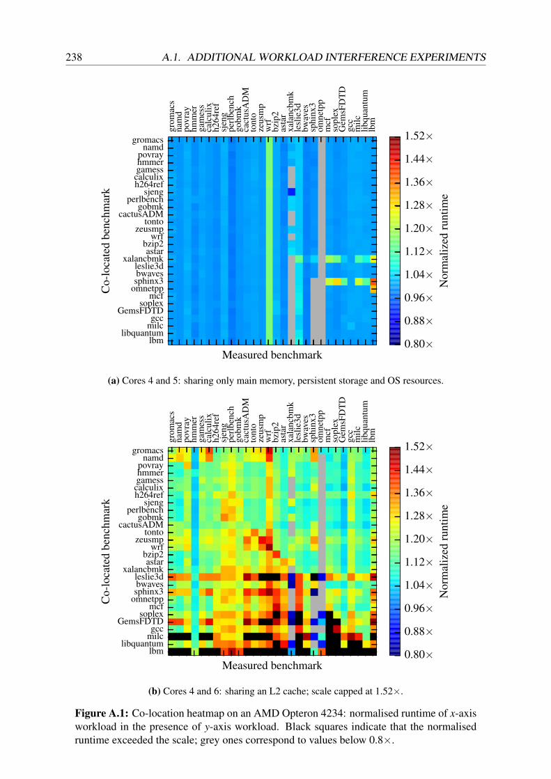
238 A.1. ADDITIONAL WORKLOAD INTERFERENCE EXPERIMENTS
grom
acs
nam
dpo
vray
hmm
erga
mes
sca
lcul
ixh2
64re
fsj
eng
perl
benc
hgo
bmk
cact
usA
DM
tont
oze
usm
pw
rfbz
ip2
asta
rxa
lanc
bmk
lesl
ie3d
bwav
essp
hinx
3om
netp
pm
cfso
plex
Gem
sFD
TD
gcc
milc
libqu
antu
mlb
m
Measured benchmarklbm
libquantummilcgcc
GemsFDTDsoplex
mcfomnetppsphinx3bwavesleslie3d
xalancbmkastar
bzip2wrf
zeusmptonto
cactusADMgobmk
perlbenchsjeng
h264refcalculixgamesshmmerpovray
namdgromacs
Co-
loca
ted
benc
hmar
k
0.80×0.88×0.96×1.04×1.12×1.20×1.28×1.36×1.44×1.52×
Nor
mal
ized
runt
ime
(a) Cores 4 and 5: sharing only main memory, persistent storage and OS resources.
grom
acs
nam
dpo
vray
hmm
erga
mes
sca
lcul
ixh2
64re
fsj
eng
perl
benc
hgo
bmk
cact
usA
DM
tont
oze
usm
pw
rfbz
ip2
asta
rxa
lanc
bmk
lesl
ie3d
bwav
essp
hinx
3om
netp
pm
cfso
plex
Gem
sFD
TD
gcc
milc
libqu
antu
mlb
m
Measured benchmarklbm
libquantummilcgcc
GemsFDTDsoplex
mcfomnetppsphinx3bwavesleslie3d
xalancbmkastar
bzip2wrf
zeusmptonto
cactusADMgobmk
perlbenchsjeng
h264refcalculixgamesshmmerpovray
namdgromacs
Co-
loca
ted
benc
hmar
k
0.80×0.88×0.96×1.04×1.12×1.20×1.28×1.36×1.44×1.52×
Nor
mal
ized
runt
ime
(b) Cores 4 and 6: sharing an L2 cache; scale capped at 1.52×.
Figure A.1: Co-location heatmap on an AMD Opteron 4234: normalised runtime of x-axisworkload in the presence of y-axis workload. Black squares indicate that the normalisedruntime exceeded the scale; grey ones correspond to values below 0.8×.

APPENDIX A. ADDITIONAL BACKGROUND MATERIAL 239
A.1.2 Pairwise application co-location: additional metrics
A.1.3 n-way SPEC CPU2006 interference experiments
In the following, I co-locate between two and twelve instances of the same SPEC CPU2006benchmark on a machine and investigate the impact of different co-locations.4 Figure A.4shows the benchmark runtime – normalised to the runtime on an otherwise idle machine – asthey are co-located on the AMD Opteron 4234 (top) and the Intel Xeon E5-2420 (bottom).Again, the benchmarks are ordered roughly from compute-bound to memory-bound accordingto Merkel et al. [MSB10].
Unsurprisingly, increased machine utilisation leads to an increase in normalised runtime forthose benchmarks that frequently access memory. By contrast, the compute-bound benchmarksdo not suffer much as a result of co-location. In the worst cases, a 4–5× slowdown occurs.
The general trend is the same for both machines, but there are some differences:
1. Sharing an L2 cache on the Opteron 4234 impacts all benchmarks by 20–50%, eventhe compute-bound ones. By contrast, sharing the Intel Xeon’s much smaller L2 cachebetween hyperthreads has no effect. This suggests that the effect observed is not dueto cache interference, but rather due to one of two other shared resources on the AMDValencia’s “Bulldozer” micro-architecture:
(a) The clustered integer core design shares a floating point unit (FPU) between adja-cent cores, akin to the Alpha 21264’s four-way integer execution [Kes99]. ManySPEC CPU2006 benchmarks make heavy use of the FPU.
(b) The shared, two-way set-associative, 64 KB L1 instruction cache of adjacent cores,which may cause additional instruction cache misses. By contrast, the Xeon has adedicated, 4-way set-associative 32 KB L1 instruction cache per core.
2. Co-location on adjacent “hyper-threads” on the Intel Xeon does not induce additionalinterference over dedicating a core to each benchmark. This result contradicts prior workusing SPEC CPU2000 and earlier-generation Intel processors [Bul05, pp. 44–56].
3. Worst-case degradation and variability across experiments are higher on the Opteron thanon the Xeon machine, possibly due to different cache sizes.
These experiments demonstrate that higher machine utilisation leads to increased co-locationinterference, especially for memory-intensive workloads.
4Running multiple instances of the same workload on a machine is not as naïve as it may seem: many clus-ter schedulers optimise for data locality, i.e. they attempt to place computations near their input data [IPC+09;ZBS+10]. If the input data to a large job is replicated to a handful of machines only, several tasks of the same jobmay end up on the same machine. Indeed, Google uses an explicit exclusivity constraint to avoid this for criticaljobs [RWH11, p. 9].

240 A.1. ADDITIONAL WORKLOAD INTERFERENCE EXPERIMENTS
HTTPQS PR BOPM
SQ
HTTP
QS
PR
BOPM
SQ
0.8×0.9×1.0×1.0×1.1×1.2×1.3×1.4×1.4×1.5×1.6×
Nor
mal
ised
cycl
es(a) Opteron: separate sockets (cores 4 and 5).
HTTPQS PR BOPM
SQ
HTTP
QS
PR
BOPM
SQ
0.8×0.9×1.0×1.0×1.1×1.2×1.3×1.4×1.4×1.5×1.6×
Nor
mal
ised
cycl
es
(b) Xeon: separate sockets (cores 4 and 5).
HTTPQS PR BOPM
SQ
HTTP
QS
PR
BOPM
SQ
0.8×0.9×1.0×1.0×1.1×1.2×1.3×1.4×1.4×1.5×1.6×
Nor
mal
ised
cycl
es
(c) Opteron: shared L3 cache (cores 4 and 8).
HTTPQS PR BOPM
SQ
HTTP
QS
PR
BOPM
SQ
0.8×0.9×1.0×1.0×1.1×1.2×1.3×1.4×1.4×1.5×1.6×
Nor
mal
ised
cycl
es
(d) Xeon: shared L3 cache (cores 4 and 6).
HTTPQS PR BOPM
SQ
HTTP
QS
PR
BOPM
SQ
0.8×0.9×1.0×1.0×1.1×1.2×1.3×1.4×1.4×1.5×1.6×
Nor
mal
ised
cycl
es
(e) Opteron: sharing L2 and L3 (cores 4 and 6).
HTTPQS PR BOPM
SQ
HTTP
QS
PR
BOPM
SQ
0.8×0.9×1.0×1.0×1.1×1.2×1.3×1.4×1.4×1.5×1.6×
Nor
mal
ised
cycl
es
(f) Xeon: adjacent hyperthreads (cores 4 and 16).
Figure A.2: Normalised cycle counts for co-located WSC applications on the AMDOpteron 4234 (left column) and Intel Xeon E5-2420 (right column). All results are forthe x-axis benchmark, normalised to its mean isolated cycle count on an otherwise idle ma-chine. Black squares indicate normalised cycle counts exceeding the scale; grey indicatesthat no results are available.

APPENDIX A. ADDITIONAL BACKGROUND MATERIAL 241
HTTPQS PR BOPM
SQ
HTTP
QS
PR
BOPM
SQ
1.60×
5.01×
2.51× 2.30×
0.8×0.9×1.0×1.0×1.1×1.2×1.3×1.4×1.4×1.5×1.6×
Nor
mal
ised
cach
e-m
isse
s(a) Opteron: separate sockets (cores 4 and 5).
HTTPQS PR BOPM
SQ
HTTP
QS
PR
BOPM
SQ
2.22×
2.02× 1.97× 22.48×
0.8×0.9×1.0×1.0×1.1×1.2×1.3×1.4×1.4×1.5×1.6×
Nor
mal
ised
cach
e-m
isse
s
(b) Xeon: separate sockets (cores 4 and 5).
HTTPQS PR BOPM
SQ
HTTP
QS
PR
BOPM
SQ
2.08×
3.58×
2.15× 2.69×
0.8×0.9×1.0×1.0×1.1×1.2×1.3×1.4×1.4×1.5×1.6×
Nor
mal
ised
cach
e-m
isse
s
(c) Opteron: shared L3 cache (cores 4 and 8).
HTTPQS PR BOPM
SQ
HTTP
QS
PR
BOPM
SQ
2.30× 2.15× 2.08×
1.85× 17.55× 21.94× 23.66×
0.8×0.9×1.0×1.0×1.1×1.2×1.3×1.4×1.4×1.5×1.6×
Nor
mal
ised
cach
e-m
isse
s
(d) Xeon: shared L3 cache (cores 4 and 6).
HTTPQS PR BOPM
SQ
HTTP
QS
PR
BOPM
SQ
2.95×
2.59×
0.8×0.9×1.0×1.0×1.1×1.2×1.3×1.4×1.4×1.5×1.6×
Nor
mal
ised
cach
e-m
isse
s
(e) Opteron: sharing L2 and L3 (cores 4 and 6).
HTTPQS PR BOPM
SQ
HTTP
QS
PR
BOPM
SQ
2.18× 2.05× 2.02×
1.78× 23.81× 36.69× 22.92×
0.8×0.9×1.0×1.0×1.1×1.2×1.3×1.4×1.4×1.5×1.6×
Nor
mal
ised
cach
e-m
isse
s
(f) Xeon: adjacent hyperthreads (cores 4 and 16).
Figure A.3: Normalised cache miss counts for co-located WSC applications on the AMDOpteron 4234 (left column) and Intel Xeon E5-2420 (right column). All results are for thex-axis benchmark, normalised to its mean isolated cache miss count on an otherwise idlemachine. Black squares indicate normalised cache miss counts exceeding the scale; greyindicates that no results are available.

242 A.1. ADDITIONAL WORKLOAD INTERFERENCE EXPERIMENTS
gromacsnamdpovrayhmmergamesscalculixh264refsjengperlbenchgobmk
cactusADMtontozeusmpwrfbzip2
astarxalancbmkleslie3dbwavessphinx3omnetpp
mcfsoplexGemsFDTD
gccmilc
libquantumlbm
0× 1× 2× 3× 4× 5× 6× 7×
Normalised runtime
1instance,isolation
2instances,differentsockets,sam
eM
CM
,differentL3,differentL
22
instances,same
socket,same
MC
M,shared
L3,differentL
22
instances,same
socket,same
MC
M,shared
L3,shared
L2
2instances,sam
esocket,differentM
CM
,sharedL
3,differentL2
2instances,differentsockets,differentM
CM
,differentL3,differentL
26
instances,same
socket,differentMC
M,shared
L3,differentL
26
instances,same
socket,same
MC
M,shared
L3,shared
L2
12instances,sam
esocket,sam
eM
CM
,sharedL
3,sharedL
2
gromacsnamdpovrayhmmergamesscalculixh264refsjengperlbenchgobmk
cactusADMtontozeusmpwrfbzip2
astarxalancbmkleslie3dbwavessphinx3omnetpp
mcfsoplexGemsFDTD
gccmilc
libquantumlbm
0× 1× 2× 3× 4× 5× 6× 7×
Normalised runtime
1instance,isolation
2instances,differentsockets,differentL
3,differentL2,dedicated
core2
instances,same
socket,sharedL
3,differentL2,dedicated
core2
instances,same
socket,sharedL
3,sharedL
2,adjacenthyper-threads12
instances,same
socket,sharedL
3,sharedL
2,adjacenthyper-threads12
instances,same
socket,sharedL
3,differentL2,dedicated
core
FigureA
.4:Interference
between
multiple
instancesof
SPEC
CPU
2006benchm
arkson
AM
DO
pteron4234
(top)and
IntelXeon
E5-2420
(bottom).V
aluesare
averagesand
standarddeviations
overthenorm
alisedruntim
esoften
executionsofeach
experiment.

APPENDIX A. ADDITIONAL BACKGROUND MATERIAL 243
A.2 CPI and IPMA distributions in a Google cluster
Figure A.5 shows that the synthetic workloads that I used in Section 8.2.1 (Table 8.2) are sit-uated towards the lower end of the CPI distribution of Google workloads. The 99th percentileCPI observed in my experiments, at around three cycles per instruction, is similar to the averageCPI at Google. This suggests that Google either over-commits machines to a greater extent, orthat the Borg scheduler fails to adequately mitigate co-location interference (or both).
Of my workloads, three (the two io_stream workloads, and the out-of-LLC mem_stream)have similar levels of memory-intensity as common Google tasks do (IPMA values below2,000), and the other two (cpu_spin and L3-fitting mem_stream) have much higher IPMAvalues that correspond to the 99th percentile for Google’s batch and service jobs.5 This suggeststhat a larger fraction of tasks are I/O-intensive or memory-intensive tasks with large workingsets, which is hardly surprising: real-world I/O is likely more bursty than the fio benchmark inmy workload (which saturates the entire disk bandwidth). Hence, real-world workloads likelypermit co-location of I/O-bound tasks, which only increases the need for interference-avoidingsolutions such as Firmament.
5With the information available in the Google trace, it is difficult to say if Google workloads usually have poorcache-affinity (which decreases IPMA), or whether the workloads are inherently memory-intensive due to largeworking sets (same effect), or if the Borg scheduler fails to avoid interference in the cache hierarchy (again, havingthe same effect).

244 A.2. CPI AND IPMA DISTRIBUTIONS IN A GOOGLE CLUSTER
0 10 20 30 40 50Cycles per instruction (CPI)
0.0
0.2
0.4
0.6
0.8
1.0
99.9
%=
41.1
2
99%
=31.1
7
90%
=7.
16
µ=
3.73
Batch avg. CPI
(a) Batch workloads, cycles per instruction(CPI). Valid n = 39,193,353.
0 10 20 30 40 50Cycles per instruction (CPI)
0.0
0.2
0.4
0.6
0.8
1.0
99.9
%=
27.6
3
99%
=24.1
2
90%
=8.
68
µ=
4.25
Service avg. CPI
(b) Service workloads, cycles per instruction(CPI). Valid n = 75,227.
0 2000 4000 6000 8000 10000Instructions per memory access (IPMA)
0.0
0.2
0.4
0.6
0.8
1.0
99%
=60
60.6
1
90%
=14
32.6
6
µ=
618.
06
Batch avg. IPMA
(c) Batch workloads, instructions per memoryaccess (IPMA). 99.99th percentile at34,482.76; valid n = 36,320,401.
0 2000 4000 6000 8000 10000Instructions per memory access (IPMA)
0.0
0.2
0.4
0.6
0.8
1.099.9
%=
4739.3
4
99%
=21
83.4
1
90%
=37
9.84
µ=
219.
93
Service avg. IPMA
(d) Service workloads, instructions permemory access (IPMA). 99.99th percentile at
9,684.85; valid n = 72,678.
Figure A.5: Performance counter data from Google workloads in the 2011 trace, based onn = 42,130,761 total tasks over 30 days. The boundaries of the shaded area correspondto the distributions of the per-task minimum and maximum observed values; the thick linerepresents the distribution of averages.

Appendix B
Additional DIOS material
B.1 DIOS system call API
B.1.1 dios_create(2)
The dios_create(2) system call is used to generate an entirely new logical DIOS object (and,consequently, a name and an initial physical object). It is the only system call that can generatelogical objects and names; every name must once have been returned by a dios_create(2)invocation.
dios_create(2) typically takes two arguments: a set of references to physical group objects(SG) for groups in which the new logical object is to be created, and a flag indicating the objecttype. Additionally, an optional host ID, optional and type-specific flags and parameters can bepassed, and a flag controls whether the logical object is named or anonymous (§4.3.1).
The return value is a tuple consisting of a fresh name (unless an anonymous logical object iscreated) and a reference to the new, initial physical object. If the logical object is not anony-mous, the new name is copied into a user-space buffer, while the reference is mapped read-onlyinto the user-space task’s address space and a pointer returned.
dios_create(SG,Pargs,host,F)→ 〈No,Ro〉
The dios_create(2) system call, called from task T, takes an optional set of referencesto physical group objects, SG, indicating the groups in which the new logical object is to becreated. dios_create(2) returns a tuple consisting of the new logical object o’s externalname, No, and a reference to the new physical object, Ro.
The kernel also computes an internal name, N io, for the new logical object and maps it to
the object structure via the local name table. Finally, the reference Ro is inserted into thetask’s reference table.
245

246 B.1. DIOS SYSTEM CALL API
The reference returned grants full permissions to the task creating the logical object, and thereference type and other parameters are set according to the initialisation flags in F .
Note that dios_create(2) does not necessarily allocate any I/O buffers or object state. Thetuple returned only contains the identifier for the logical object and a handle for the physicalobject; buffers to interact with it and other state are typically set up lazily on the first I/O request.In other words, dios_acquire_read(2) and dios_acquire_write(2) must be employedafter dios_create(2) to effect any I/O on the physical object.
An interesting bootstrapping challenge arises from the fact that names are stored in user-providedmemory (unlike references). The names of the initial logical objects in a program must there-fore be stored in static memory or on the stack; a typical DIOS “pattern” is to allocate a privatememory blob on startup that ends up storing further logical objects’ names.
B.1.2 dios_lookup(2)
The ability to locate physical objects by resolving their names to locations is an important partof I/O DIOS. I described the name resolution process in Section 4.3.3; it is implemented by thedios_lookup(2) system call.
dios_lookup(2) takes a name as its argument and returns a set of references to reachablephysical objects corresponding to this name. Reachable in this context means:
(a) that the corresponding logical object is named (i.e. not anonymous),(b) that the logical object is in a group that the calling task is a member of,(c) that the physical object in question is either local, or(d) if the physical object is remote, that it exists on a machine which can receive DCP mes-
sages from the local machine and responds to them (i.e. it has not failed, and no networkpartition separates it from the task’s local machine).
All reachable physical objects found then have references generated for them. The referencegeneration applies similar transformation to a reference delegation (see §4.5.3) to adapt thereference attributes for the local context. The resulting new references are inserted into thelocal task’s reference table.
In other words, dios_lookup(2) is defined as follows:
dios_lookup(No,F) → Ro | o ∈ reachable(No,GT)
dios_lookup(No,Rg,F) → Ro | o ∈ reachable(No,g)
The dios_lookup(2) system call invoked by task T takes an external name, No, as itsargument and returns a set of references corresponding either (i) to all reachable physicalobjects for logical object o named by No in all of T’s groups g ∈ GT; or (ii) to all reachablephysical objects for logical object o in group g, if an explicit Rg is specified.

APPENDIX B. ADDITIONAL DIOS MATERIAL 247
To do so, the kernel computes either (i) the internal names for No in each group g that Tis a member of, or (ii) the internal name for No in g, respectively, by computing N g
o =
H(No ‖ g), and looks up N go in the name table.
As implied in above definitions, dios_lookup(2) makes no guarantee to return all physicalobjects for the logical object corresponding to the name specified in the argument, but onlyreachable ones. In other words, name resolution for remote physical objects is best-effort,although a reliable interconnect can help increase the confidence of comprehensive results beingreturned.
Additionally, dios_lookup(2) merely guarantees to return references for all physical whichwere reachable at the point of handling the system call. This may include stale information: thephysical objects found may already have been deleted or new ones created when the system callreturns (see §4.8).
B.1.3 dios_copy(2)
As explained in Section 4.5.3, references can be delegated to other tasks. This is facilitated bythe dios_copy(2) system call.
dios_copy(2) takes three arguments: a reference to delegate, a reference to the target task thatit is to be delegated to, and a specification of the desired transformations. The second referencemust refer to a task-type physical object; if it does not, the dios_copy(2) invocation fails.
The return value indicates whether the delegation succeeded. Note that the delegating task doesnot itself gain access to the delegated reference, unless it is delegating to itself.
dios_copy(Ro,RTd ,Ptransform,F) → bool
The dios_copy(2) system call, when invoked by task T, takes a reference, Ro, and aspecification of desired transformations (pointed to by Ptransform). It delegates a transformedcopy of Ro to the task Td referred to by RTd .
The newly created reference is inserted into Td’s reference table, and a message notifyingTd of the delegation is enqueued to be read from its self-reference.
dios_copy(2) is a complex and powerful system call. It checks the validity of the referencedelegation requested, transforms the reference into a new reference as appropriate for the targetcontext, and communicates the delegation to the target task and its managing kernel. Transfor-mations are described in Section 4.5.3, and may involve copying the physical object data.

248 B.1. DIOS SYSTEM CALL API
Tasks can delegate references to themselves in order to create transformed versions of them; inpractice, this usually happens in order to pass the references to a different task, however, anddirect delegation is preferable.
There are several possible future extension to the dios_copy(2) system call:
1. It can be used to dynamically add logical objects to groups by permitting the target refer-ence to refer to a physical group object. Instead of inserting a new reference into a task’sreference table, this invocation on a reference to physical object o, Ro, with external nameNo, would insert an internal name N g
o for the target group g in the name tables. In orderto maintain security, however, only logical objects from groups that the calling task is amember of can be copied.
2. “Move semantics” for reference delegation might be supported, allowing a reference tobe delegated to another task with the caller losing access to it.
These extensions are not currently implemented in the DIOS prototype, but are in principlecompatible with the current API.
B.1.4 dios_delete(2)
While dios_create(2) is responsible for creating names and references, there must also be away of destroying them when no longer required. Note that the deletion of handles (references),identifiers (names), and physical objects are separate concerns.
The DIOS dios_delete(2) system call is used to remove references from the current task’sreference table, i.e. deleting the reference. Deletion of a reference only mandatorily destroysthe handle, however: what happens to the physical object referred to depends on its deletionmode (§4.2):
• A reference-counted physical object has its reference count decremented and is destructedonce it reaches zero; at this point, it may either be reclaimed immediately or continue toexist in an orphaned state for asynchronous garbage-collection.
• If the physical object is one-off deleted, it is removed atomically, and any other referencesto it become invalid and system calls on them fail.
• For an immortal physical object, nothing happens (other than the reference being dropped).
The corresponding logical object’s name is deleted from the name table once the last physicalobject for it is removed.
Under ordinary circumstances (i.e. in the absence of failures), dios_delete(2) always re-turns true if a valid reference Ro is passed.
Hence, the dios_delete(2) system call is defined as follows:

APPENDIX B. ADDITIONAL DIOS MATERIAL 249
dios_delete(Ro,F) → bool
The dios_delete(2) system call takes a reference, Ro, to a physical object o, and deletesit from the calling task T’s reference table.
A deletion handler specific to physical object o’s deletion mode is invoked before returning,and any outstanding I/O requests on the reference being deleted are implicitly aborted (i.e.terminated without commit).
Finally, the dios_delete(2) call returns a success indication.
Since dios_delete(2) directly mutates the state of an existing physical object and affectsthe validity of names and references for it, race conditions with other system calls are subtle.Consider, for example, dios_delete(2) racing with an invocation of dios_copy(2): if thedeletion is handled first, the delegation effected by dios_copy(2) will fail as the referenceno longer exists. However, if the delegation is handled first, it succeeds and the reference issubsequently deleted.
In other words, deletion of a reference does not guarantee that delegated copies of this refer-ence do not continue to be made after the call to dios_delete(2) is made (although this isguaranteed after dios_delete(2) returns). A consequence of these semantics is that runningdios_lookup(No) to obtain the set of references corresponding to No’s physical objects andthen invoking dios_delete(Ri
o) on each reference Rio returned does not guarantee that all
physical objects described by these references will be deleted.
As the deletion always affects the task-local reference table only, no other dios_delete(2)call on the same reference can race in the network; local races within the task are idempotent,although the second call to be serviced may return false, indicating a now-invalid referencewas passed.
Finally, a task may delete its self-reference using dios_delete(2). This is a special case: ithas the effect of terminating the task (and thus does affect the logical task object). However,the task is not completely removed until all other references to it are destroyed. It remains in a“zombie” state (no longer executing and unable to communicate) until this is the case.
Finally, an exiting task implicitly invokes dios_delete(2) on all of the references in itsreference table. Since the table is destroyed immediately after, this is only consequential asother machines may need to be notified of the reduced reference count for the physical objects.
B.1.5 dios_run(2)
A task can invoke the dios_run(2) system call in order to spawn a further task. The exe-cutable argument must be a reference to a durable blob or a blob of executable memory. If the

250 B.1. DIOS SYSTEM CALL API
reference does not have the executable permission set, dios_run(2) fails. The new task is achild of the current task.
Since a task’s group memberships are determined at creation time, the dios_run(2) systemcall also specifies the group memberships to be inherited by the newly created child.
dios_run(2) takes a set of references to physical group objects representing groups of whichthe child task is to be granted membership. Any physical group object available to the parenttask which was not obtained by group name resolution can be a member of this set. Thisargument is optional; if it is not specified, an empty set is assumed, and the default behaviour isto give membership of a single, newly generated group to the spawned task.
The dios_run(2) system call returns a reference to the newly spawned physical task object,and is defined as follows:
dios_run(Rbin,SG,Pinfo,F)→ RTC
The dios_run(2) system call, when invoked by parent task TP, takes a reference to anexecutable physical object (a binary), Rbin, and a set of references to physical group objects,SG, as arguments. It causes a child task, TC, to be created.
A reference to the new physical task object for TC, RTC is returned.
The child task’s set of group memberships, GC, is set to SG, which is defined as:
SG = Rg | g ∈ GP or g ∈CP,
where GP stands for the parent task’s group memberships and CP for the groups created bythe parent task.
Note that as a result of these semantics, the child task can resolve either:
1. a subset of the names that the parent can resolve (if only groups that the parent task is amember of are passed);
2. a disjoint set of names compared to those that the parent resolve (if no groups or onlygroups created by the parent are passed);
3. a superset of the names that the parent can resolve (if all groups that the parent task is amember of are passed and all groups created by the parent task are passed);
4. a partially overlapping set of names with those that the parent can resolve (if a mixture ofinherited and created groups are passed).
DIOS tasks may be placed by the long-term cluster task scheduler, explicitly spawned on aspecific remote machine, or constrained to running locally on the same machine as their parent.Hence, dios_run(2) can have two different effects depending on the flags specified:

APPENDIX B. ADDITIONAL DIOS MATERIAL 251
1. If it is invoked with the SPAWN_LOCAL flag set, the new task is started on the same ma-chine. The kernel creates a new local task and sets it runnable.
2. If the SPAWN_LOCAL flag is not present, and a specific host ID is set in the Pinfo structure,a DCP message is sent to spawn the task on the host specified.
3. Finally, if SPAWN_LOCAL is not set, and no explicit host ID is specified, message is sent tothe cluster manager, which will place the task and execute it by invoking dios_run(2)
with appropriate arguments.
Either way, the parent task is blocked until the child task is running unless the NON_BLOCKINGflag is set.
The newly created task starts out with the default set of initial references and an otherwiseempty reference table. It does not share any of its parent’s references unless they are explicitlydelegated to it subsequently.
B.1.6 dios_pause(2) and dios_resume(2)
When a DIOS application needs to suspend itself or another task, it can use the dios_pause(2)system call. Likewise, dios_resume(2) can be used to continue executing a suspended task.
dios_pause(2). The argument to dios_pause(2) must be a reference to a physical taskobject; if it is not, an error is returned. DIOS changes the referenced task’s state to “suspended”and deschedules it if it is running.
dios_pause(RT,F)→ bool
The dios_pause(2) system call pauses the execution of a task T. It takes a reference toT’s physical task object, RT, as its argument. The kernel notifies the kernel on the machinerunning T to suspend its execution. If T is already suspended or it has exited, the call hasno effect.
If T was suspended successfully, the return value is true; otherwise, it is false.
Invoking dios_pause(2) on a task’s self-reference (Rself) is a special case. It has the effect ofyielding the processor with immediate effect. If the STAY_RUNNABLE flag is set, the task staysrunnable. Otherwise, it is suspended until dios_resume(2) is invoked on it by another task.
dios_resume(2). A suspended task T can be continued by any other task invoking thedios_resume(2) system call with RT as its argument. dios_resume(2) is the counterpart

252 B.1. DIOS SYSTEM CALL API
to dios_pause(2) and its operation is analogous. The only difference is that a task cannotinvoke dios_resume(2) on a reference to itself.
In practice, dios_pause(2) and dios_resume(2) calls are primarily used by the clusterscheduler. However, in combination with an extended dios_copy(2) system call, they couldalso support task migration: a task would be paused, copied, the original deleted and the newcopy resumed.1
B.1.7 dios_acquire_read(2)
The dios_acquire_read(2) system call initiates a read-only I/O request. It takes a referenceto a physical object o as its argument and returns an I/O vector (a buffer of a defined length) forI/O on this reference or an error indication.
When invoked, dios_acquire_read(2) attempts to read the specified number of bytes (oras many bytes of data as possible, if size is zero) from the physical object o referred to by Ro.
dios_acquire_read(2) is a buffer-acquiring system call: when it returns, the kernel sup-plies the user application with a read buffer containing physical object data. Several buffermanagement options are available by passing appropriate flags:
1. ACQUIRE_IOV_CREATE (default): creates a buffer for the reference. When reading, thisbuffer holds data; when writing, it may hold data for blobs, but not for streams.
2. ACQUIRE_IOV_TAKE: accepts an existing buffer as an argument, acquires ownership ofit and uses it; the buffer is deleted on release.
3. ACQUIRE_IOV_BORROW: accepts an existing buffer and holds it until it is released, butdoes not acquire ownership. When dios_release_read(2)/dios_release_write(2)is called, the buffer is returned to the original owner, but not destroyed.
4. ACQUIRE_IOV_REUSE: reuses an existing, already associated buffer to be passed andrecords the start of a new I/O request on it (e.g. by copying a current version number).
5. ACQUIRE_IOV_NONE: does not associate a new or existing buffer but sets up referenceI/O state. Subsequent calls may create, move, or borrow buffers.
The second option (ACQUIRE_IOV_TAKE) is useful for zero-copy I/O, as it allows movingbuffers obtained from an earlier acquire operation on a different reference. The fourth option(ACQUIRE_IOV_REUSE) allows the caller to use a buffer multiple times, which significantlyreduces the number of memory mappings required compared to a full acquire-use-release cycle.
1The current DIOS prototype does not yet support copying of physical task objects, but well-known processmigration techniques such as checkpoint-restart (implemented e.g. by BLCR [DHR02]) can be used to add thisfacility.

APPENDIX B. ADDITIONAL DIOS MATERIAL 253
All buffers are allocated by the kernel: this permits different underlying mechanisms to exposedata in different ways. For example, a shared memory area may expose copy-on-write pages inthe buffer, while a high-performance network transport (e.g. DPDK, netmap [Riz12]) accessinga remote physical object may expose NIC buffers directly. On the other hand, a double-bufferedshared memory ring between tasks may copy the data into a new temporary buffer to enablereceipt of additional data.
In other words, the dios_acquire_read(2) system call can be specified as follows:
dios_acquire_read(Ro, size, sem, F) → 〈P,size〉
The dios_acquire_read(2) system call attempts to initiate a read-only I/O request onphysical object o referred to by Ro. The optional size parameter specifies how the amountof data that must be available before the call returns; if it is unset, all available data is read.The sem parameter specifies the desired concurrent access semantics.
If the desired concurrent access semantic can be satisfied, the I/O request is registered byincrementing the physical object’s active read request counter (§4.7).
If a new buffer is instantiated (i.e. the ACQUIRE_READ_IOV_CREATE flag is set), it ismapped into the calling task’s virtual address space.
dios_acquire_read(2) returns a tuple 〈P,size〉 that contains a pointer to the buffer(P) and an indication of its length (size).
The underlying I/O mechanism can be based either on a streaming abstraction (as in most net-work transports, or FIFO IPC between tasks) or on a fixed-size blob abstraction (§4.2). In theblob case, the buffer returned typically corresponds to the entire physical object or a subsetthereof, although an optional argument can specify an offset. For streams, the offset argumentends up discarding data until the offset is reached.
Any data read from the buffer returned by dios_acquire_read(2), however, are not defi-nitely valid until dios_commit_read(2) has been called to complete the I/O request. Onlyif dios_commit_read(2) indicates that the read was valid under the concurrent access se-mantics specified in sem, the data can be treated as valid. If an application does not depend onconsistency, it may use data from the read buffer directly; if it does depend on the integrity ofthe data read, it must copy the buffer and call dios_commit_read(2) before using it.
B.1.8 dios_commit_read(2)
A DIOS I/O request is not valid until it has been committed. On read, a successful commitconfirms that the data supplied at the acquire stage are still valid.
For read-only I/O requests, this is the role of the dios_commit_read(2) system call. Itvalidates the I/O request and informs the user-space application by returning an error if the data

254 B.1. DIOS SYSTEM CALL API
read have been affected by another concurrent I/O request (usually a write) under the request’sconcurrent access semantics.
By default, dios_commit_read(2) expects to be given a buffer already associated with thereference Ro passed, but flags can customise this:
1. COMMIT_IOV_USE (default): accepts an associated buffer and commits it; the buffer re-mains associated and ready for re-use.
2. COMMIT_IOV_MOVE: accepts an existing buffer from a different reference, takes owner-ship of it, and commits it before returning.
In the second case, the commit’s return value indicates the validity of the buffer with regardsto the original reference that it was acquired on. No indication of the validity of the buffer isgiven with regard to the target reference – an acquire-commit cycle must be completed if thisis needed.
The dios_commit_read(2) system call is thus defined as follows:
dios_commit_read(Ro, 〈P, size〉, F) → bool
The dios_commit_read(2) system call takes a buffer and attempts to commit it, return-ing a validity indication
If the commit succeeds, the data read were definitely valid, and the physical object’s readversion counter is atomically incremented. If the commit fails, the read version counter isnot incremented.
In either case, the physical object’s active reader count is atomically decremented.
The precise semantics of a failed commit depend on the underlying physical object. Some un-derlying I/O mechanisms may not guarantee the integrity of a buffer while it is shared with theuser-space application: consider, for example a shared memory area that can be written to byanother task. While failed commits indicate such a concurrent access in excess of the permissi-ble semantics, the application may have read corrupt data. It is the application’s responsibilityto ensure that this failure can either be recovered from, or that synchronisation is employed suchthat this situation cannot occur.
B.1.9 dios_release_read(2)
Since buffers are a limited resource, they must eventually be returned to the kernel for reuse.The dios_release_read(2) system call cleans up and tears down any related state for aread buffer. If the buffer is borrowed, it is returned to its previous owner; if it is owned, it isde-allocated.

APPENDIX B. ADDITIONAL DIOS MATERIAL 255
dios_release_read(2) normally returns true; only invalid arguments can lead to an error.The system call is thus defined as follows:
dios_release_read(Ro,〈P, size〉, F) → bool
The dios_release_read(2) system call returns an active buffer to the kernel.
The buffer at P is invalidated and unmapped from user-space virtual memory.
dios_release_read(2) can typically be handled entirely locally, even if the physical objectis remote, since the buffer contains local state only. After dios_release_read(2) is called,the buffer passed is no longer valid for user-space access, even though it may be unmappedasynchronously. The kernel may, however, re-use the buffer immediately, returning it fromanother buffer-acquiring system call.
B.1.10 dios_acquire_write(2)
Like dios_acquire_read(2), dios_acquire_write(2) is a buffer-supplying call. How-ever, instead of returning a buffer containing data available for reading, it returns a – blank orpre-populated – buffer for writing. The application then copies its data into the buffer, or gen-erates them directly in the buffer. Finally, dios_commit_write(2) is called to finalise theoutput request and check its validity.
The size of the buffer is requested by the user is passed as an optional argument, the defaultbeing Ro’s write_buf_size attribute (if set). The system call may return a larger buffer thanrequested; for example, it may page-align the buffer for easier mapping to user-space.
The definition of the dios_acquire_write(2) system call is similar to the definition ofdios_acquire_read(2):
dios_acquire_write(Ro, size, sem, F) → 〈P,size〉
The dios_acquire_write(2) system call attempts to initiate a write I/O request onphysical object o referred to by Ro. The optional size parameter specifies the amountof data that will be written; if it is unset, a default-sized buffer is returned.
If the desired concurrent access semantic (specified via the sem parameter) can be satis-fied, the I/O request is registered by incrementing the physical object’s active write requestcounter (§4.7).
If a new buffer is instantiated (i.e. the ACQUIRE_IOV_CREATE flag is set), it is mapped intothe calling task’s virtual address space.
dios_acquire_write(2) returns a tuple 〈P,size〉 that contains a pointer to the buffer(P) and an indication of its length (size).
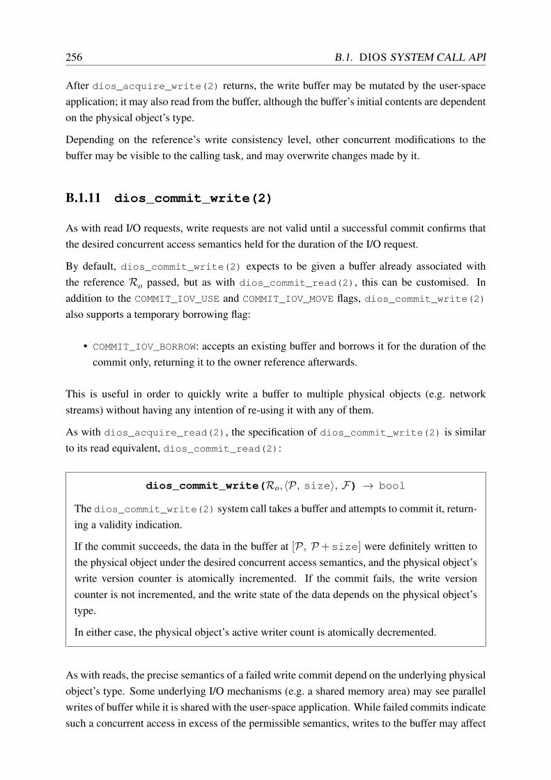
256 B.1. DIOS SYSTEM CALL API
After dios_acquire_write(2) returns, the write buffer may be mutated by the user-spaceapplication; it may also read from the buffer, although the buffer’s initial contents are dependenton the physical object’s type.
Depending on the reference’s write consistency level, other concurrent modifications to thebuffer may be visible to the calling task, and may overwrite changes made by it.
B.1.11 dios_commit_write(2)
As with read I/O requests, write requests are not valid until a successful commit confirms thatthe desired concurrent access semantics held for the duration of the I/O request.
By default, dios_commit_write(2) expects to be given a buffer already associated withthe reference Ro passed, but as with dios_commit_read(2), this can be customised. Inaddition to the COMMIT_IOV_USE and COMMIT_IOV_MOVE flags, dios_commit_write(2)also supports a temporary borrowing flag:
• COMMIT_IOV_BORROW: accepts an existing buffer and borrows it for the duration of thecommit only, returning it to the owner reference afterwards.
This is useful in order to quickly write a buffer to multiple physical objects (e.g. networkstreams) without having any intention of re-using it with any of them.
As with dios_acquire_read(2), the specification of dios_commit_write(2) is similarto its read equivalent, dios_commit_read(2):
dios_commit_write(Ro,〈P, size〉, F) → bool
The dios_commit_write(2) system call takes a buffer and attempts to commit it, return-ing a validity indication.
If the commit succeeds, the data in the buffer at [P, P +size] were definitely written tothe physical object under the desired concurrent access semantics, and the physical object’swrite version counter is atomically incremented. If the commit fails, the write versioncounter is not incremented, and the write state of the data depends on the physical object’stype.
In either case, the physical object’s active writer count is atomically decremented.
As with reads, the precise semantics of a failed write commit depend on the underlying physicalobject’s type. Some underlying I/O mechanisms (e.g. a shared memory area) may see parallelwrites of buffer while it is shared with the user-space application. While failed commits indicatesuch a concurrent access in excess of the permissible semantics, writes to the buffer may affect

APPENDIX B. ADDITIONAL DIOS MATERIAL 257
the physical object even though the commit failed.2 As with reading, it is the application’sresponsibility to tolerate this failure or perform synchronisation such that this situation cannotoccur.
B.1.12 dios_release_write(2)
Once a user-space program has completed and committed the output written into a write buffer(supplied by dios_acquire_write(2)), the buffer must eventually be returned to the kernelwhen it is no longer needed.
As with dios_release_read(2), this operation is defined as follows:
dios_release_write(Ro,〈P, size〉, F) → bool
The dios_release_write(2) system call returns an active buffer to the kernel.
The buffer at P is invalidated and unmapped from user-space virtual memory.
In most cases, a dios_release_write(2) system call – unlike the acquire and commit calls– can be handled entirely locally; only an implicit commit (RELEASE_IOV_COMMIT) may re-quire a remote operation.
B.1.13 dios_select(2)
When an application performs I/O on multiple references, it may need to determine whichreference to service next. This functionality is typically implemented using dios_select(2)
loops in conventional OSes.3
The DIOS dios_select(2) system call implements synchronous parallel waiting on multiplereferences, returning the reference that becomes available first. It is defined as follows:
dios_select(R0, . . . ,Rk, mode, F)→ Ri
The dios_select(2) system call returns the first reference that has data available for I/Oof mode (read, write) out of the set of references, R0, . . . , Rk, passed to it. The caller isblocked until one of the references in the set becomes ready for I/O.
The most common use of dios_select(2) involves asynchronous servicing of multiple stream-type references, either for reading or writing. The abstraction is useful, as it avoids blocking thecaller when no data are available, and because it is more efficient than polling.
2Techniques like shadow copies and copy-on-write paging can be employed to avoid this in the object-level I/Oimplementation, but DIOS does not mandate them in the API.
3Alternative systems with slightly different semantics – e.g. Linux’s epoll notifications – are also used.

258 B.1. DIOS SYSTEM CALL API
When a reference passed refers to a remote physical object, a DCP message is sent to the remotekernel to inform it of the reference being in a selector. When the physical object becomes readyfor I/O, the remote kernel sends a notification to all kernels that have references to the physicalobject in selectors.4
Finally, it is worth noting that dios_select(2) can easily be extended to support timed wait-ing by passing a reference to a physical timer object which becomes ready after a certain timehas elapsed.
4If references to the physical object exist in multiple selectors, all are notified; the relevant tasks may then startI/O requests that race for the data unless they synchronise otherwise.

Appendix C
Additional Firmament material
C.1 Minimum-cost, maximum-flow optimisation
C.1.1 The min-cost, max-flow problem
The minimum-cost, maximum-flow problem is an optimisation problem on a flow network.1
Intuitively, it aims to find the cheapest way to move a given ingress volume of material to anegress destination such that (i) throughput is maximised, and (ii) the cost is minimised. Anapt real-world example is the scheduling of goods distribution over a road network: a maximalnumber of goods ought to be delivered per day in the most economical way possible.
A flow network is typically expressed as a directed graph (G) with cost-weighted arcs (E) andvertices (V ), the latter optionally having a supply of flow (“sources”) or a demand for absorbingit (“sinks”).
The optimisation goal is the juxtaposition of two existing problems: finding the maximum flowfrom sources to sinks (the maximum flow problem) and the minimum-cost (≡ shortest) pathfrom the sources to the sinks (the shortest path problem). Figure C.1 shows an example flownetwork with cost and capacity annotations, and the minimum-cost, maximum-flow solution.
A flow corresponds to a set of paths (which may include cycles) through the network. In otherwords, the flow is a global property of the network. By contrast, the flow fe on an arc e = (v,w)is a local property of this arc, and must satisfy two properties:
1. fe = f (v,w)≥ cmin(v,w) and f (u,w)≤ cmax(v,w), where cmin and cmax denote the lowerand upper limits on the flow capacity of the arc (the capacity constraint), i.e. each arc’sflow must be within the permissible range bounded by its capacities); and
1Minimum-cost maximum-flow is related, but not identical to the “minimum-cost flow problem”. The latteronly aims to find a minimum-cost flow, rather than the maximal minimum-cost flow. The literature, however,frequently uses the two terms synonymously.
259

260 C.1. MINIMUM-COST, MAXIMUM-FLOW OPTIMISATION
A
B
C
D
E
F
5, 4/9
1, 4/4
3, 4/5
4, 5/5
7,0/
9
8,1/9
1,0/9
2, 3/3
5, 5/9
Figure C.1: Minimum-cost, maximum-flow optimisation example: vertex A is the source,vertex F is the sink; arcs are labelled as “cost, flow/capacity”. Arc width is proportional tothe flow carried, and the minimum-cost, maximum-flow solution at cost 95 is highlightedin red.
2. fe = f (v,w)=− f (w,v) (the anti-symmetry constraint), i.e. any positive flow is matchedby a negative flow in the opposite direction.
If only these two properties are satisfied, the flow on the arc is a pseudoflow. If, in addition, italso satisfies flow conservation, it is a circulation:
∑(v,w)∈E
f (v,w) = ∑(v,w)∈E
f (w,v) for each vertex v ∈V that is not a source or sink,
i.e. flow coming into a vertex must leave it again, since only sources can generate flow and onlysinks can drain it.
Finally, the overall graph G must drain all flow generated at sources via one or more sinks:
∑w∈V
f (s,w) = d and ∑w∈V
f (w, t) = d,where s is the source vertex and t is the sink vertex.2
This is the required flow constraint: flow generated at the source must be drained by a sink –in other words, flow cannot vanish inside the network (other than via a sink).
The total cost of a given circulation C is equal to
a(C) = ∑(v,w)∈E
f (v,w)×a(v,w),
where a(v,w) ∈ R denotes the cost on arc (v,w).3 In other words, the total cost equates to thesum of, for each arc, the per-arc cost multiplied by the units of flow across the arc.
2While a flow network can have multiple sources and sinks, it can always be transformed into one with a singlesource and sink by adding two vertices s and t that generate and drain the aggregate flow. Connecting s to allsources and all sinks to t with appropriate capacities preserves the original network.
3Real-valued costs are possible in theory, but most efficient solvers use integer-valued costs.
APPENDIX C. ADDITIONAL FIRMAMENT MATERIAL 261
C.1.2 The cost-scaling push-relabel algorithm
In the following, I summarise Goldberg’s cost-scaling minimum-cost, maximum-flow optimi-sation algorithm [Gol97], which forms the basis of the cs2 and flowlessly solvers for Fir-mament.
Definitions. In addition to the terms already defined in the previous section, several others arerelevant to the cost-scaling push-relabel algorithm:
The excess at a vertex is the difference between its incoming flow and its outgoing flow. Thevertex cannot yet be part of a circulation if the excess is non-zero, as this violates conser-vation of flows.
Residual capacity describes the remaining capacity of an arc after subtracting existing flowthrough it: residual(v,w) = cmax(v,w)− f (v,w). Consequently, the residual graph is theset of arcs whose residual capacity is non-zero (i.e. that still have “spare” capacity).
ε-optimality at intermediate stages is an integer measure of the maximum factor by whichthe total cost of the current flow in the network is greater than the optimal minimum-costflow. In other words, an ε-optimality of two means that the current solution is at mosttwice as expensive as the best solution; an ε-optimality of one indicates that the optimalsolution has been found.
The price is a per-vertex quantity that is used to hold state of a partial solution in severalalgorithms. Specifically, the notion of a minimum-cost circulation depends on the priceassignments: for a price-extended cost function ap(v,w) = a(v,w)+price(v)−price(w),a minimum-cost circulation exists if (and only if) there exists a function price such that∀(v,w).ap(v,w) < −ε ⇒ f (v,w) = cmax(v,w). In other words, price assigns prices tovertices in such a way that a price less than −ε corresponds to each arc saturated withflow (i.e. with no residual capacity).
An admissible arc is an arc whose reduce cost is less than −ε . An arc becomes admissibleeither due to change in ε or due to a change in price at either vertex.
Algorithm. I show a simplified version of the cost-scaling approach in Algorithm C.1. Intu-itively, the core iteration of the algorithm can be understood in terms of a network of commer-cial trade activity for a specific commodity (e.g. oil): each vertex represents a trader who buysand sells the commodity at a specified price, while the sinks represent the ultimate consumer.Naturally, it is in each trader’s interest to maximise her turnover (≡ flow) at minimal cost.

262 C.1. MINIMUM-COST, MAXIMUM-FLOW OPTIMISATION
1. Initialisation:
(a) set ε = α , such that α is larger than the maximum cost of an arc in the flow network,and
(b) initialise Q as an empty FIFO queue.
2. Iteration: while ε > 0, if the flow network is not ε-optimal (i.e., there exists excess atsome v ∈V or at least one arc has a reduce cost <−ε),
(a) for each vertex v ∈V ,
i. send the maximum flow possible on all admissible outgoing arcs.
(b) for each vertex v ∈V ,
i. append to Q if v has any excess.
(c) while Q is not empty, pull v from its head,
i. if v has any outgoing admissible arcs, push flow along those arcs until either:A. all excess has been drained; orB. no more admissible outgoing arcs exist.
ii. if v still has excess and there are no admissible arcs left, relabel v:A. reduce the price of v by ε ,B. make admissible any arcs whose reduce cost is now negative,C. repeat from 2(c)i.
(d) once no vertex has excess and there are no admissible arcs with a reduce cost ≤−ε ,
i. divide ε by α , andii. repeat from 2a.
3. Termination: return the ε-optimal flow.
Algorithm C.1: Simplified outline of Goldberg’s cost-scaling push-relabel algorithm forminimum-cost, maximum-flow optimisation [Gol97].
Excess stock at a particular trader motivates the trader to attempt to sell her stock onwards,4
which she does as long as her business partners (≡ neighbours) are willing to buy at the askingprice (step 2(c)i in Algorithm C.1).
When no business partner is willing to buy at the asking price, but further excess stock remains,the trader must reduce her price in order to keep selling (step 2(c)ii). Once she does so, her busi-ness partners may become interested again. As a side-effect, however, the trader also reducesher buying price, and thus becomes a less attractive customer to her own suppliers, therebyreducing her expected future stocking levels.
In practice, this algorithm is too slow unless it is improved by the application of heuristicsthat reduce the number of push and relabel operations. For example, the cs2 solver relies
4In this fictive trade network, no trader ever has an interest in storing stock: she either consumes it herself, oris willing to sell it onwards at any price. It follows that no profit is ever made in this capitalist venture!

APPENDIX C. ADDITIONAL FIRMAMENT MATERIAL 263
on arc fixing, which only rarely considers arcs that are unlikely to change; price refinement,which decays the ε-optimality criterion more rapidly; push lookahead, which invokes an early“relabel” operation to avoid flow becoming “stuck”; and price update, which updates prices atmany vertices in one go [Gol97].
Future algorithmic improvements. Progress on the minimum-cost, maximum-flow optimi-sation problem is still being made, often based on improvements to solvers for the underlyingmaximum-flow problem [GT14]. For example, Király and Kovács in 2012 showed that Gold-berg’s improvements to the push-relabel algorithm for maximum flow [Gol08] also apply to theminimum-cost, maximum-flow problem [KK12].
A recent maximum-flow algorithm by Orlin has worst-case O(V E) time complexity [Orl13],improving on a prior bound of O(V E logE/V logV(V )) by King et al. [KRT94]. Further improve-ments to the leading minimum-cost, maximum-flow solvers may follow from this result.
C.2 Flow scheduling capacity assignment details
Each arc in a flow network has a capacity within a range [capmin,capmax] bounded by the min-imum and maximum capacity. In Firmament, as in Quincy, capmin is generally zero, whilethe value of capmax depends on the type of vertices connected by the arc and the cost model.5
Table C.1 lists common capacity assignments for combinations of vertices.
Each task vertex (Ti) generates a single unit of flow. Thus, all arcs exiting from a task vertexhave unit capacity, independent of whether they point to the cluster aggregator (X), an unsched-uled aggregator (U j), or a rack or machine vertex (Rk, Ml).
Similarly, at the far end of the network, each arc from a machine vertex (Ml) to the sink (S) hasa fixed capacity K.6 This corresponds to the number of tasks that may be scheduled on eachmachine in the WSC. Accordingly, the capacity of the arc from a rack vertex (Rk) to each ofits subordinate machine vertices might be set to K, and the capacity of the arc from the clusteraggregator to the rack vertex might be set to mK, where m is the number of machines in therack.
Any excess flow that corresponds to unscheduled tasks (i.e. generated flow ≥ rmK, where r isthe number of racks) must be drained via the unscheduled aggregator vertices. Firmament, likeQuincy, specifies a minimum number of tasks that must be scheduled for a job j at all times(E j). It also specifies a maximum number that may be scheduled concurrently (Fj). Clearly,0 ≤ E j ≤ Fj ≤ N j, where N j is the total number of tasks in job j. Enforcing E j ≥ 1 guarantees
5For simplicity, I use “the capacity” to refer to the maximum capacity value in the following.6Quincy actually sets K = 1 [IPC+09, app., p. 275], although the possibility of sharing machines is discussed
in the paper [IPC+09, §8]. A modern WSC composed of many-core machines requires K > 1.

264 C.2. FLOW SCHEDULING CAPACITY ASSIGNMENT DETAILS
T0,0
T0,1
T0,2
T1,0
T1,1
X
R0
M0
M1
R1
M2
M3
S
U0
U1
1
1
1
1
1
1
1
1
1
1
mK
mK
K
K
K
K
K
K
K
K
F0 −E0
F1 −E1
1
1
Figure C.2: The flow network in Figure 6.1 with example capacities on the arcs, repeatedfrom Figure 6.2.
Edge Capacity NotesTi → Ml 1 Specific machine preference.Ti → Rk 1 Rack preference.Ti → X 1 Wildcard, may schedule anywhere.Ti → U j 1 Possibility of remaining unscheduled.Rk → Ml K For K tasks on the machine.X → Rk mK For m machines in the rack.Ml → S K For K tasks on the machine.U j → S Fj −E j For 1 ≤ E j ≤ Fj ≤ N j; N j is the number of tasks in job j.
Table C.1: Edge capacity parameters for different arc types in the Quincy scheduler.
starvation freedom by ensuring that at least one task from each job is always running [IPC+09,app., pp. 275–276].
To ensure that the upper bound Fj is maintained, each unscheduled aggregator vertex also gen-erates a flow of Fj −N j. Since this is negative (as Fj ≤ N j), this actually amounts to draining aflow of |Fj −N j|. This makes sense, because:
• N j −Fj (≡ |Fj −N j|) tasks cannot schedule, as they would exceed the upper bound Fj;• Fj −E j tasks may schedule, but may also remain unscheduled by reaching the sink via
the unscheduled aggregator; and• E j tasks must schedule by reaching the sink through machine vertices.
By draining the flow for N j −Fj tasks at U j, and with the sink’s demand set to −∑ j(Fj), allpossible solutions to the optimisation satisfy this demand. Any solution that drains all flow

APPENDIX C. ADDITIONAL FIRMAMENT MATERIAL 265
generated in the network must route at least N j −Fj flow through U j, since there is no otherway for this flow to be drained (as it has been deducted from the demand at the sink vertex).
In order to enforce the lower bound on the number of tasks scheduled (E j), the unscheduledaggregator vertices must ensure that it is never possible for more than N j −E j tasks to send ordrain flow through them. The only other way for flow to reach the sink is through the resourcetopology, so this limitation forces E j tasks to be scheduled. The limit is enforced by settingthe capacity of U j’s outgoing arc to the sink to Fj −E j. At most Fj flow can remain after thelocal demand of Fj −N j is satisfied, but E j flow must be forced to drain via other ways, givingFj −E j remaining flow to drain via the sink.
The upper (Fj) and lower (E j) bounds on the number of runnable tasks can be varied to enforcefairness policies (cf. §2.3.4). I elaborate on this in Section 6.3.2.
While the capacities are used to establish possible scheduling states of tasks (as well as toenforce fairness constraints), the costs associated with arcs in the flow network are used todescribe how preferable a possible scheduling assignment is. Some cost terms are general andalways assigned in the same way, but others are configurable, allowing different schedulingpolicies to be expressed. I explain the general cost terms in the next section, and describe fourspecific cost models configuring others in Section 7.
C.3 Quincy cost model details
The original Quincy paper describes a cost model based on co-optimisation of data locality, pre-emption cost, and task scheduling delay [IPC+09, §4.2]. These dimensions are mutually depen-dent: good data locality reduces runtime, but may require either waiting for a suitable machineto become available (increasing wait time) or preempting an already running task (wasting workthat needs to be re-done).
Quincy assumes that the tasks’ input data reside in a distributed filesystem on the same cluster,i.e. remote data can be fetched from any machine (as in GFS [GGL03], TidyFS [FHI+11] andFDS [NEF+12]), but incorporates data locality into the cost model.
Table C.2 gives an overview of the costs Quincy assigns to different arcs, as well as other costparameters not specific to arcs. The relations between these parameters and the cost expressionsassigned to arcs are summarised in Table C.3. The costs are expanded in terms of the expectedtime required to transfer remote input data, a task’s cumulative wait time, and, if applicable, thetime for which a task has already been running once it is scheduled.
In all cases that involve placement of a task in a location where it is not currently running, thecost is calculated by multiplying the cost of transferring remote input data across the top-of-rack switch (ψ) and the cluster aggregation switch (ξ ) with the amount of remote data required.R(Ti, j) indicates the number of bytes that must be copied from machines within the same rack;X (Ti, j) is the number of bytes that must be pulled in from other racks for task T j,i.

266 C.3. QUINCY COST MODEL DETAILS
Parameter Edge Meaningv j
i T j,i → U j Cost of leaving T j,i unscheduled.α
ji T j,i → X Cost of scheduling in the worst possible location.
ρj
i,l T j,i → Rl Cost of scheduling on worst machine in rack.γ
ji,m T j,i → Mm Cost of scheduling or continuing to run on machine Mm.ψ – Cost of transferring 1 GB across ToR switch.ξ – Cost of transferring 1 GB across aggregation switch.d∗ – Data transfer cost for given locality (data term).p∗ – Opportunity cost of preemption (preemption term).
Table C.2: Cost parameters in the Quincy cost model and their roles.
T0,0
T0,1
T0,2
T1,0
T1,1
X
R0
M0
M1
R1
M2
M3
S
U0
U1
α 00
α 01
α02
α10
α11
v00
v01
v0 2
v 10
v11
0
0
0
0
0
0
0
0
0
0
0
0
γ ′10,M3
γ02,M1
Figure C.3: The example flow network in Figure 6.1 with costs according to the Quincycost model added to the arcs. The capacities are assigned as in Figure C.2.
As the scheduler runs, it may choose to route flow for a running task through a different ma-chine to the one that the task was originally assigned to. This choice carries not only the costof the new assignment (as described above), but also an opportunity cost of preempting (i.e.,terminating) the already-running task and potentially wasting work.7
The opportunity cost of preempting a task is expressed by the preemption term, p∗. This is setto θ
ji , the number of seconds for which task T j,i has already been running anywhere, whether
on the current machine or as part of another prior assignment. In other words, p∗ grows withtime as the task runs. The preemption term is applied as a discount to the cost of continuingto run in the same location: effectively, continuing to run a task running becomes increasingly
7The exact amount of work wasted depends on whether a preempted task runs from the beginning once it isassigned to a machine again. Many distributed applications use checkpointing or similar techniques to save partialresults of a task, especially in batch computations [LGZ+14, §4; MMI+13, §3.4; GLG+12, §7.5].

APPENDIX C. ADDITIONAL FIRMAMENT MATERIAL 267
Parameter Valuev j
i ωνj
iα
ji ψRX(T j,i)+ξX X(T j,i)
ρj
i,l ψRRl (T j,i)+ξX R
l (T j,i)
γj
i,m
d∗ if not runningd∗− p∗ if running on m
d∗ψRC
m(T j,i)+ξXCm (T j,i)
p∗ θj
i
Table C.3: Parameter values used in the Quincy cost model.
attractive over time and thus carries a reduced cost. Any better assignment that might lead toa preemption or a migration to a different machine must offer an advantage of more than −p∗
over the current assignment’s cost.
The Quincy cost model is powerful and yields good assignments in a wide range of practicalsettings [IPC+09, §6]. However, it suffers from a number of limitations:
1. It does not consider interference between tasks due to sharing machine resources. Whilethe K parameter in the flow network capacities allows for co-location (see §6.2.1), allco-location opportunities are treated equally.
2. It assumes that machines are homogeneous and that a task’s runtime on a machine onlydepends on input data locality. As I showed in Section 2.1.3, this is rarely the case inWSCs.
In the following sections, I describe two cost models that I developed for Firmament to addressthese limitations.
C.4 Flow scheduling limitation details
In Section 6.3.4, I outlined features of scheduling policies that are difficult to express directlyusing Firmament’s flow network optimisation.
In the following, I explain the challenging policies in more detail using examples, and sketchhow the techniques of multi-round scheduling and admission control allow Firmament to modelthem nevertheless.
C.4.1 Combinatorial constraints and global invariants
The flow network representation is versatile, but it is not a panacea: there are desirable schedul-ing properties that it cannot easily express.

268 C.4. FLOW SCHEDULING LIMITATION DETAILS
Combinatorial constraints are constraints that have mutual dependencies (also sometimes re-ferred to as “correlated constraints”). Firmament assumes that the decision to place a task ona resource (by routing flow through it) is independent of the other decisions (placements, pre-emptions, or migrations) made in the same scheduling round.
As a result, it is challenging to express mutually dependent scheduling constraints in Firmament(e.g. “if T0 goes here, T1 must go there”, where both T0 and T1 are both unscheduled). Forexample, this includes the following types of constraints:
Co-scheduling constraints: “tasks of this job must run on the same rack/machine” or “tasksof this job must never share a rack/machine”.
Distance constraints: “this pair of tasks must have no more than two switch hops betweenthem”.
Conditional preemption: “if this task is placed, another task must be preempted as a result”.
n-choose-k constraints: “at least k out of n tasks of this job must be scheduled at the sametime, or none must be”.
Many of these can be handled by reactive multi-round scheduling (§6.3.1) and the n-choose-kconstraint can be modelled using Firmament’s support for relaxed gang scheduling (§6.3.3).
Few other schedulers support generalised combinatorial constraints. One exception is the workby Tumanov et al. (alsched [TCG+12] and tetrisched [TZP+16]), which models scheduling as aMixed Integer Linear Problem (MILP).
Global invariants are difficult to express if they require dependent assignments, as these amountto combinatorial constraints. On common global invariant is a fairness policy.
Some fairness policies can be expressed with the aid of the unscheduled aggregator verticesenforcing bounds on the number of runnable tasks (§6.3.2), but others cannot. For example, apolicy that guarantees equal shares of preferable co-location assignments across users can onlybe enforced reactively, and one that guarantees fair shares of cross-rack bandwidth can only beenforced by admission control.
There are other global invariants that amount to dependent decisions. For example, Google’sscheduler supports a per-job “different machine” invariant [RWH11, p. 9], which ensures that notwo jobs in a task share a machine. “No more than two web search tasks may share a machine”or “no two tasks with large inputs may start in a rack at the same time” are difficult invariantsfor Firmament to enforce in a single scheduling round. However, Firmament can support this,and the other invariants mentioned, via reactive multi-round scheduling.
Likewise, a strict global priority order for preemption (i.e. “no higher-priority task ever getspreempted by a lower-priority task”) can only be expressed with carefully bounded dynamiccost adjustments. If, for example, costs are increased based on wait time (as done in Quincy), along-waiting low-priority task may – in the absence of a bound – end up preempting a higher-priority task once its cost is sufficiently high.

APPENDIX C. ADDITIONAL FIRMAMENT MATERIAL 269
C.4.2 Multiple scheduling dimensions
Multi-dimensional resource models are common in practical WSC environments [RTG+12;SKA+13]. In the flow network approach, each unit of flow atomically represents a task. Re-sources’ arcs to the sink have an integer flow capacity that regulates the number of tasks thatmay schedule on a leaf resource. As observed in the Quincy paper [IPC+09, §8], this approachdoes not take into account the multi-dimensionality of tasks’ resource requirements.
Ideally, “capacity”-type resource dimensions – such as the free memory on a machine, or sharesof disk or network bandwidth – would be expressed directly via flow network capacities. How-ever, this would require routing flow in multiple dimensions, which is impossible with unam-biguous results when using the minimum-cost, maximum-flow optimisation. Another approach– multi-commodity minimum-cost, maximum-flow optimisation – supports multiple “commodi-ties” flowing from sources to sinks at the same time, but still assumes one-dimensional arccapacities. Extending the problem to multiple capacity dimensions would involve tracking vec-tors of flow across each arc.
Such tracking of flow vectors is unlikely to become feasible within reasonable time: even sim-ple multi-commodity flow problems without cost minimisation are NP-complete [EIS75, §4]and solving vectorised capacities would require solving the (also NP-complete) bin packingproblem. However, it might be possible to simplify the problem with good heuristics in thespecific domain of task scheduling.
There is a way to enable multi-dimensional resource models in Firmament: admission control.Tasks that do not fit sufficiently in all resource dimensions can either (i) be rejected before beingadded to the flow network, or (ii) have their scheduling opportunities restricted by removing theoption of scheduling via the wildcard aggregator (X). The CoCo cost model (§7.3) uses thelatter approach.
C.5 Firmament cost model API
Listing C.1 shows the current Firmament cost model API.

270 C.5. FIRMAMENT COST MODEL API
1 class CostModelInterface 2 virtual Cost_t TaskToUnscheduledAggCost(TaskID_t task_id) = 0;3 virtual Cost_t UnscheduledAggToSinkCost(JobID_t job_id) = 0;4 virtual Cost_t TaskToResourceNodeCost(TaskID_t task_id,5 ResourceID_t resource_id) = 0;6 virtual Cost_t ResourceNodeToResourceNodeCost(7 const ResourceDescriptor& source,8 const ResourceDescriptor& destination) = 0;9 virtual Cost_t LeafResourceNodeToSinkCost(ResourceID_t resource_id) = 0;
10 virtual Cost_t TaskContinuationCost(TaskID_t task_id) = 0;11 virtual Cost_t TaskPreemptionCost(TaskID_t task_id) = 0;12 virtual Cost_t TaskToEquivClassAggregatorCost(TaskID_t task_id,13 EquivClass_t tec) = 0;14 virtual pair<Cost_t, int64_t> EquivClassToResourceNodeCost(15 EquivClass_t ec,16 ResourceID_t res_id) = 0;17 virtual Cost_t EquivClassToEquivClassCost(EquivClass_t tec1,18 EquivClass_t tec2) = 0;19 /**20 * Methods to determine equivalence classes.21 */22 virtual vector<EquivClass_t>* GetTaskEquivClasses(TaskID_t task_id) = 0;23 virtual vector<ResourceID_t>* GetOutgoingEquivClassPrefArcs(24 EquivClass_t tec) = 0;25 virtual vector<TaskID_t>* GetIncomingEquivClassPrefArcs(26 EquivClass_t tec) = 0;27 virtual vector<ResourceID_t>* GetTaskPreferenceArcs(TaskID_t task_id) = 0;28 virtual pair<vector<EquivClass_t>*, vector<EquivClass_t>*>29 GetEquivClassToEquivClassesArcs(EquivClass_t tec) = 0;30
31 /**32 * Machine and task management.33 */34 virtual void AddMachine(ResourceTopologyNodeDescriptor* rtnd_ptr) = 0;35 virtual void AddTask(TaskID_t task_id) = 0;36 virtual void RemoveMachine(ResourceID_t res_id) = 0;37 virtual void RemoveTask(TaskID_t task_id) = 0;38
39 virtual FlowGraphNode* GatherStats(FlowGraphNode* accumulator,40 FlowGraphNode* other) = 0;41 virtual void PrepareStats(FlowGraphNode* accumulator) 42 virtual FlowGraphNode* UpdateStats(FlowGraphNode* accumulator,43 FlowGraphNode* other) = 0;44
45 /**46 * Debug information47 */48 virtual const string DebugInfo() const;49 virtual const string DebugInfoCSV() const;50
Listing C.1: The Firmament cost model API header.