Embed Size (px)
Citation preview
OPERATING SYSTEM MANUAL FOR
REVISED TEXAS TRAFFIC ASSIGNMENT SYSTEM
by
Charles W. Blumentritt Associate Project Supervisor
Research Report Number 60-5
Traffic Assignment Research Project Number 2-8-63-60
Sponsored by
The Texas Highway Department In Cooperation with the
U o S. Department of Commerce, Bureau of Public Roads
March, 1965
TEXAS TRANSPORTATION INSTITUTE Texas A&M University College Station, Texas
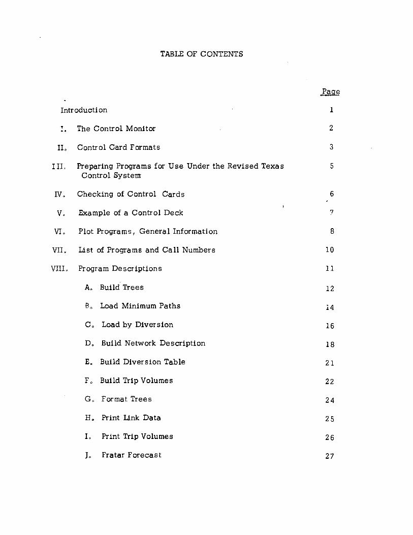
TABLE OF CONTENTS
Introduction
I. The Control Monitor
IL Control Card Formats
UL Preparing Programs for Use Under the Revised Texas Control System
IV. Checking of Control Cards
v. Example of a Control Deck
VL Plot Programs 0 General Information
VII. List of Programs and Call Numbers
VIIL Program Descriptions
A,. Build Trees
B,. Load Minimum Paths
c. Load by Diversion
D. Build Network Description
E. Build Diversion Table
F. Build Trip Volumes
G. Format Trees
H. Print Link Data
L Print Trip Volumes
J. Fratar Forecast
1
2
3
5
6
7
8
10
11
12
14
16
18
21
22
24
25
26
27
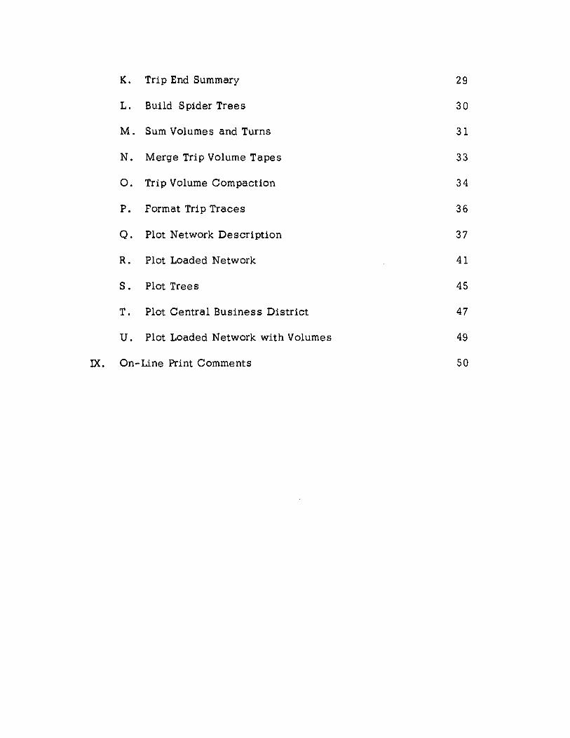
K. Trip End Summary 29
L. Build Spider Trees 30
M. Sum Volumes and Turns 31
N. Merge Trip Volume Tapes 33
0. Trip Volume Compaction 34
P. Format Trip Traces 36
Q. Plot Network Description 37
R. Plot Loaded Network 41
s. Plot Trees 45
T. Plot Central Business District 47
u. Plot Loaded Network with Volumes 49
IX. On-Line Print Comments 50
INTRODUCTION
This manual is designed to aid the user in the operation of the revised Texas Traffic Assignment System. Data formats are explained in detail, in"cluding program input as well as program control cards.
The user should become familiar with the contents of this manual, particularly in regard to error stops and the causes thereof. Minor modifications can be made to data on-line if careful attention is paid to the effects and recoveries of the error stops.
This assignment package currently includes twenty-one of the progr'ams most frequently used by the Texas Highway Department, including plot programs. Additional programs have been used under the Texas Control System, but their inclusion in this basic system manual is considered unnecessary since users will often want to incorporate their own speoialized programs in the assignment package.
This manual assumes that the user is familiar with the basic operation of the IBM 709/90/7094 series, and no attempt has been made to explain basic computer operation. Anyone unfamiliar with the principles of operation involved should refer to their respective machine manual covering these points.
The excellent assistance given by Joe Mitchell and William Pry in preparing this manual is hereby acknowledged.
1
i I ,,
I"
I. THE CONTROL MONITOR
The Control Monitor provides the means for operating the assignment package in an prderly and efficient manner. The functions of the Control Monitor are as follows:
( 1 ) Reads the parameter card constants 1 converts them from decimal to binary mode I and stores them in fixed locations for subsequent use by programs in the assignment package.
( 2 ) Reads switch cards and sets internal switches for use in controlling the operation of the assignment programs.
( 3 ) Provides for the control of tape units by means of control cards.
( 4 ) Reads and stores data for use in heading the pages of output listings.
( 5 ) Searches for 1 loads from the program tape 1 and initiates the operation of a requested program in the traffic assignment package.
All of these operations are performed when appropriate control cards are read.
2
0 0 1 6 * *PARAM
*HEADR
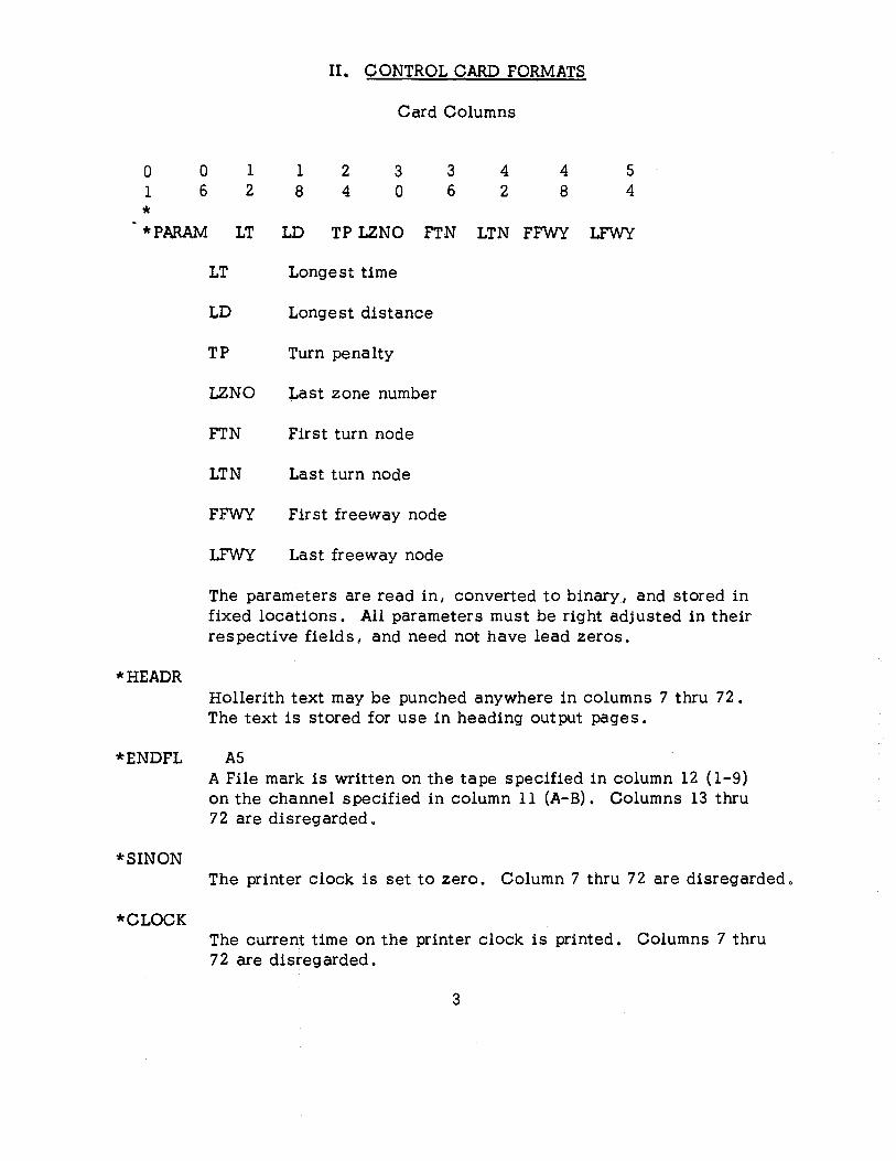
II. CONTROL CARD FORMATS
Card Columns
1 1 2 3 3 4 4 5 2 8 4 0 6 2 8 4
LT LD TP LZNO FTN LTN FFWY LFWY
LT Longest time
LD Longest distance
TP Turn penalty
LZNO Last zone number
FTN First turn node
LTN Last turn node
FFWY First freeway node
LFWY Last freeway node
The parameters are read in I converted to binary I and stored in fixed locations. All parameters must be right adjusted in their respective fields, and need not have lead zeros.
Hollerith text may be punched anywhere in columns 7 thru 72. The text is stored for use in heading output pages.
*ENDFL AS
*SINON
*CLOCK
A File mark is written on the tape specified in column 12 (1-9) on the channel specified in column 11 (A-B). Columns 13 thru 72 are disregarded o
The printer clock is set to zero. Column 7 thru 72 are disregarded o
The current time on the printer clock is printed. Columns 7 thru 72 are disregarded.
3
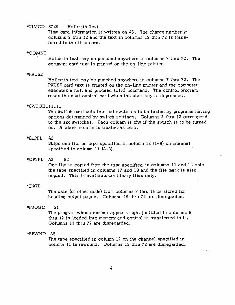
*TIMCD 8749 Hollerith Text
*COM NT
*PAUSE
Time card information is written on AS. The charge number in columns 9 thru 12 and the text in columns 19 thru 72 is transferred to the time card.
Hollerith text may be punched anywhere in columns 7 thru 7 2. The comment card text is printed on the on-line printer.
Hollerith text may be punched anywhere in columns 7 thru 7 2. The PAUSE card text is printed on the on-line printer and the computer executes a halt and proceed (HPR) command. The control program reads the next control card when the start key is depressed.
*SWTCH 111111 The Switch card sets internal switches to be tested by programs having options determined by switch settings. Columns 7 thru 12 correspond to the six switches. Each column is ohe if the switch is to be turned on. A blank column is treated·as zero.
*SKPFL A2 Skips one file on tape specified in column 12 (1-9) on channel specified in column 11 (A-B).
*CPYFL A2 B2
*DATE
One file is copied from the tape specified in columns 11 and 12 onto the tape specified in columns 17 and 18 and the file mark is also copied. This is available:· for binary files only.
The date (or other code) from columns 7 thru 18 is stored for heading output pages. Columns 19 thru 72 are disregarded.
*PROGM 51 The program whose number appears right justified in columns· 6 thru 12 is loaded into memory and control is transferred to it. Columns 13 thru 72 are disregarded.
*REWND AS The tape specified in column 12 on the channel specified in column 11 is rewound. Columns 13 thru 72 are disregarded.
4
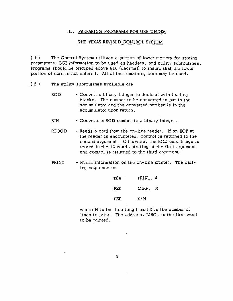
III. PREPARING PROGRAMS FOR USE UNDER
THE TEXAS REVISED CONTROL SYSTEM
( :t ) The Control System utilizes a portion of lower memory for storing parameters 1 BCI information to be used as headers, and utility subroutines. Programs should be origined above 610 (decimal} to insure that the lower portion of core is not entered. All of the remaining core may be used.
( 2 ) The utility subroutines available are
BCD - Convert a binary integer to decimal with leading
BIN
RDBCD
blanks. The number to be converted is put in the accumulator and the converted number is in the accumulator upon return.
- Converts a BCD number to a binary integer.
- Reads a card from the on-line reader. If an EOF at the reader is encountered I control is returned to the second argument. Otherwise 1 the BCD card image is stored in the 12 words starting at the first argument and control is returned to the third argument.
- Prlnts information on the on-line printer. The calling sequence is:
TSX PRINT, 4
PZE MSG1 N
PZE X*N
where N is the line length and X is the number of lines to print. The address, MSG I is the first word to be printed"
5
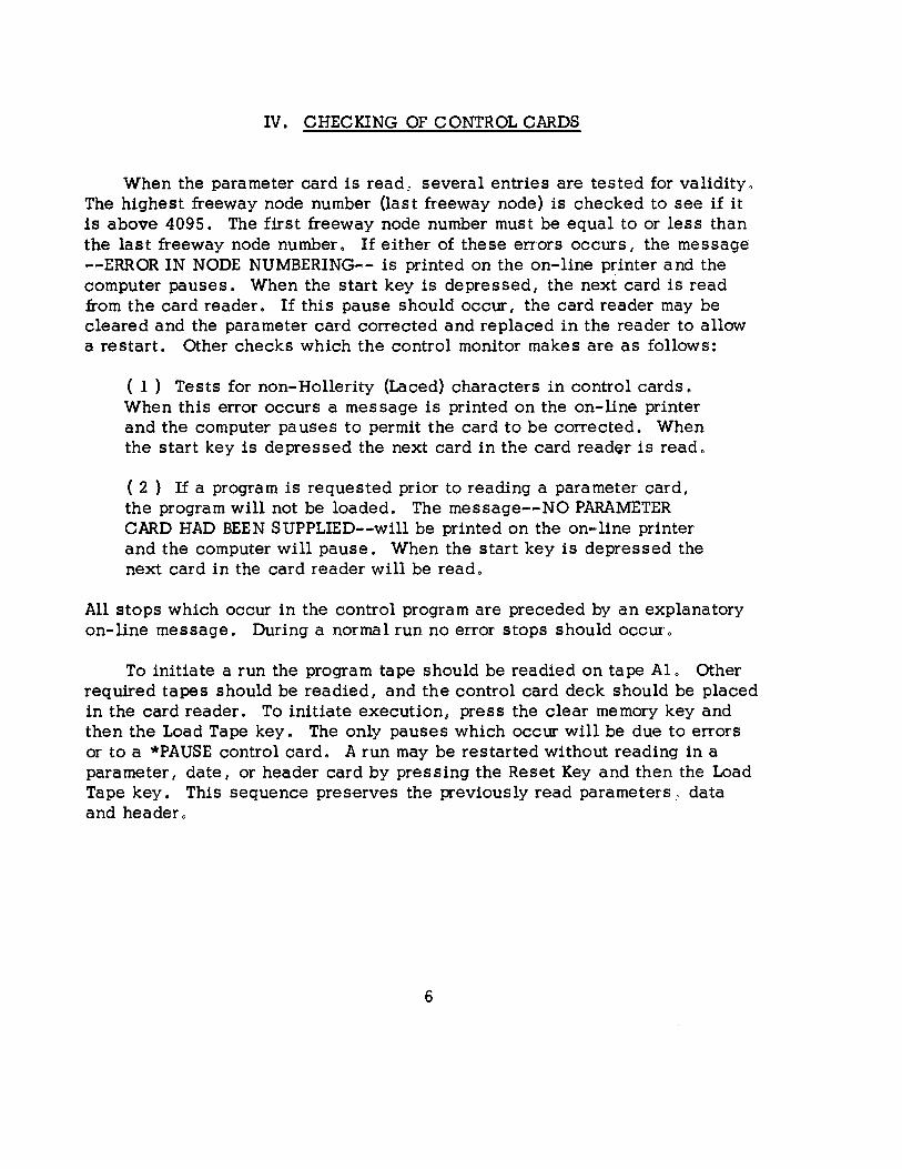
IV. CHECKING OF CONTROL CARDS
When the parameter card is read, several entries are tested for validity, The highest freeway node number {last freeway node) is checked to see if it is above 4095. The first freeway node number must be equal to or less than the last freeway node number. If either of these errors occurs, the message --ERROR IN NODE NUMBERING-- is printed on the on-line printer and the computer pauses. When the start key is depressed, the next card is read from the card reader. If this pause should occur, the card reader may be cleared and the parameter card corrected and replaced in the reader to allow a restart. Other checks which the control monitor makes are as follows:
( 1 ) Tests for non-Hollerity (Laced) characters in control cards. When this error occurs a message is printed on the on-line printer and the computer pauses to permit the card to be corrected. When the start key is depressed the next card in the card read~r is read.
( 2 ) If a program is requested prior to reading a parameter card, the program will not be loaded. The message--NO PARAMETER CARD HAD BEEN SUPPLIED--will be printed on the on-line printer and the computer will pause. When the start key is depressed the next card in the card reader will be read.
All stops which occur in the control program are preceded by an explanatory on-line message. During a normal run no error stops should occur.
To initiate a run the program tape should be readied on tape Al. Other required tapes should be readied, and the control card deck should be placed in the card reader. To initiate execution, press the clear memory key and then the Load Tape key. The only pauses which occur will be due to errors or to a *PAUSE control card. A run may be restarted without reading in a parameter, date, or header card by pressing the Reset Key and then the Load Tape key. This sequence preserves the previously read parameters.· data and header.
6
v. EXAMPLE OF A CONTROL DECK
0 0 1 1 2 3 3 4 4 5 1 6 2 e 4 0 6 2 a 4
*f1>ARAM 620 150 20 2.23 .2.25 1.213 1001 1.213 *COMNT THO 40 ON A6tTHD 73 ON 8.2, THO 71 ON A3 *PAUSE SCRATCH TAPES ON A2t A5t 81 *REWND A!5 REWIND OUTPUT TAPE *DATE MAR 26t 196!5 *SWTCH'00001 0 FREEWAYS AT FULL TIME *PROG,_. *HEADR *PROGM *PROGM
5 BUILD NETWORK CORPUS CHRISTI MINIMUM PATH NETWORK SC~EME 83
12 PRINT LZ.NK DATA 1 BUILD TREES z. !5 9 CORPUS CHRISTl MINIMUM PATH TREES SCHEME 83
11 FORMAT TREES 2· !5 9 1 BUILD TREES
223
6 6 0 6
1
*HEADR *PROGM
1 *PROGM
1
*HEADR *PROGM
1
CORPUS CHRISTI ·83 SCHEME MINIMUM PATH NEW 1963 TRIPSCTHD 73) 2 LOAD MINIMUM PATHS
223 1 223 1 1000 200
*SWTCH110000 *PROGM 17 SUM VOLUMES AND TURNS *ENDFL A!5 *REWND A!5 *PAUSE SIGN OFF AND LIST OUTPUT TAPE AS *TIMCO 021G AUSTIN A2 MINIMUM PATH ASSIGNMENT
7 2
VI. PLOT PROGRAMS, GENERAL INFORMATION
The publication--Traffic Assignment Plot Systems--by W. F. Pry, available from the_Texas Highway Department, Austin 14, Texas, is a necessary reference for users desiring to plot network configurations using the Texas A&M Assignment System. The decimal plot output tapes generated by the plot programs were designed for use with an IBM 1401 digital computer in conjunction with a California Computer Products Model 565 Digital Incremental Plotter. Slight program modification is necessary if the plotter to be used is of a different configuration than the 565 or if a different supporting computer is used. Refer to the above mentioned publication for a complete guide to network plotting and program specifications.
The output for all plot programs is on unit A4. This tape is not rewound after any plot program is used. This enables each program to continue the output on the same tape. Each program reads a library of node·'location coordinates from tape B3.
The following is a sample control card deck for a traffic assignment run using the plotting capabilities.
8
0 0 1 1 2. 3 3 4 4 s 1 6 2. 8 4 0 6 2. 8 4
*COMNT THO 40 ON A6t 73 ON 82.. 71 ON A3t 98 ON *PAUSE SCRATCH TAPES ON A2., A4t AS, 81 •
*REt.LND A5 REWIND OUTPUT TAPE *REWND A4 REWIND PLOT TAPE *DATE .JULY 2.1t 1965
*PAR AM 320 428 336 1230 1500 *SWTCH000010 FREEWAYS AT FULL TIME *PROGM 5 BUILD NETWORK *HEADR *PROGM *PROGM
CORPUS CHRISTI MINIMUM PATH NETWORK SCHEME 83 12 PRINT LINK DATA 23 PLOT NETWORK DESCRIPTION
3 3 c N 1 RED BLUE GREEN 2.
A
*PROGM 1
*HEADR *PROGM
1 *PROGM
L F 4 1 BUILD TREES
223 CORPUS CHRISTI MINIMUM PATH TREES SCHEME B3
11 FORMAT TREES 2.. s 9
25 PLOT TREES 3BLACK T 1 2· 5 9
*PROGM 2. LOAD MINIMUM PATHS 1 223 1 223 1 1000
*PROGM 2.4 PLOT LOADED NETWORK NUMBER 2 DIRECT 3 3 c v N 1 RED BLUE GREEN 2
1000 5000 1000 5000 1000 5000 3 A L F 4
DIRECT 3 4 c v N 1 RED BLUE GREEN BLACK * * 2
1 5000 1 500 501 1000 1001 5000 3 A F F F 4
*PROGM 17 SUM VOLUMES AND TURNS *ENDFL AS END FILE OUTPUT TAPE *REWND A5 REWIND OUTPUT TAPE *F AUSE PLOT TAPE A4e PRINT TAPE A5e *TIMCD 8749 PUNCH TIME CARD
6 6 7 0 6 2.
83
Program Number 0
1
2
3
5
8
10
11
12
13
14
15
16
17
19
22
50
Plot Programs
23
24
25
26
27
VI. UST OF PROGRAMS
Title Control
Build Trees
Load Minimum Paths
Load by Diversion
Build Network De scription
Build Diversion Table
Build Trip Volumes
Format Trees
Print Link Data
Print Trip Volumes
Fratar Forecast
Trip End Summary
BuHd Spider Trees
Sum Volumes and Turns
Merge Trip Volumes
Trip Volume Compaction
Format Trip Traces
Plot Network Description
Plot Loaded Net work
Plot Trees
Plot Central Business District
Plot Loaded Network Volumes 10
VIII. PROGRAM DESCRIPTIONS
11
... -=z- - .. -- -
Function-
The Build Trees Program computes the minimum paths from selected zone centroids to all other nodes in the network.
Input-
( 1 ) The network description as built by the network builder program and read from tape A2.
( 2 ) A control card which specifies the trees to be built, If a single tree is to be built 1 the corresponding zone number is right justified in columns 1 thru 6.
Example - Specify tree 14
14 (Col. 5 & 6)
If it is desired to specify two or more trees whose corresponding zone numbers are not consecutive I the zone numbers are right justified in adjacent six column fields and followed by commas except for the last one.
Example - Specify trees 14, 17, and 64
14, 171 64
To specify a group of trees whose corresponding zone numbers are consecutive I the first and last zone numbers are right justified in adjacent six column fields.
Example - Specify trees 1 thru 223
1 223
Two or more groups of consecutively numbered trees may be specified by separating the pairs of zone numbers specifying the groups with commas.
Example - Specify trees 1 thru 141 19 thru 43 1 89 thru 12 7
1 141 19 431 89 127
Any combination of the above types of specifications may be used.
Example - Specify trees 12 and 33 thru 40
121 33 40
12
Output -
The minimum path trees are written on tape A3. If more than one reel is required for the trees 1 the program automatically switches to tape A4 when the "reel on A3 is full. The trees are written in binary format 1 one tree per physical record. The first word of the record is an identification word and contains the tree number. The length of the tree records is N words plus the ID word 1 where N is the highest node number.
Options -
There are no options in the tree builder.
Error Notices and Stops -
All error stops are preceded by error messages.
-END OF FILE AT CARD READER- Prepare a tree select control card I ready it in the card reader, and press the start key. -TREE SELECT CARD IN ERROR - Place corrected select card in reader and press start . -READ ERROR ON NETWORK DESCRIPTION TAPE- Check to see if network description is on A2 and press start to try again.
Normal Operation -
The tree builder reads the network description and control card and begins calculations of trees. The trees will be written on the output tape at slightly varying intervals. The time required to build a tree on the IBM 7094 varies from . 3 to 1. 2 seconds approximately I depending on the size of the network. If more than one reel is required for the trees 1 the message -- BEGAN REEL 2 WITH TREE X-- will be printed on-line. X will be the number of the first tree on the second reel.
13

B. Load Minimum Paths - Program 2
Function-
The Load Minimum Paths Program loads selected zones and selected destinations. Time limits (upper and lower) are specified for loadfng 1 as well as the first external station number.
Input-
( 1 ) The network description as built by Program 5 1 Build Network Description. (A2)
( 2 ) The trip volumes as prepared by one of the following: (B2)
(A) Program 10 1 Build Trip Volumes
( B ) Program 14 1 Fratar Forecast
( C ) Program 19 1 Merge Trip Volumes
(D) Program 22 1 Trip Volume Compaction
( 3 ) Three control cards in the on-line card reader:
( A ) The origin zones to be loaded
( B ) The destination zones to be loaded
( C ) Limits for loading and the first external station number
Examples of zones to be loaded and destinations to be loaded may be found in the discussion of the centroid selection card in Program 11 Build Trees. The format of the limits card is as follows:
Output-
Column
1- 6 7-12
13-18
Information
Lower time limit Upper time limit First external station number
The loaded network (binary) is written on tape Bl. Zone to Zone 1 Zone to Stationt and Station to Station trip length distribution tables are 'lAir itten on tape
14
AS (BCD) for printing. The turn table is also on Bl.
Options-
· There are no options in the Load Minimum Paths Program.
Error Notices and Stops -
.. NETWORK NOT COMPATIBLE WITH PARAMETERS,. The parameter card and/or the network description must be corrected and the load restarted. "NO DESTINATION SELECTION CARD--READY IN CARD READER AND PRESS START,. Prepare a destination selection card and place in card reader. 11 ERROR IN DESTINATION SELECTION CARD. CORRECT, READY IN CARD READER 1
AND PRESS START" Either the first centroid selected is zero 1 or at some point 1
the next selected destination is lower than the previously selected destination. "TREE TRACE IN EXCESS OF 300 LINKS. TO SKIP THIS TREE AND CONTINUE, PRESS START II 11 NO LOWER TIME LIMIT SPECIFIEDG PUSH START TO BEGIN LOADING,. Press start to load all trips. 11 READ ERROR ON FREEWAY TREE TAPE" Press start to retry the operation. 11 READ ERROR ON ZONE TRIP TAPE B2 11 Press start to retry the operation. 11 READ ERROR ON TAPE A2 11 Press start to retry the operation. "NO FREEWAY TREE, ZONE N,. Press start to ignore zone N. 11 NO ORIGIN SELECTION CARD--READY ONE IN READER, PRESS START .. 11 END OF TAPE ON AS. DIAL IN A NEW OUTPUT TAPE. PUSH START TO CONTINUE,.
Normal Operation -
The load program reads the control cards specifying the origin zones to be loaded 1 the destination zones to be loaded I and the upper and lower time limits for loading. The network description is read and checked against the parameters reported. A turn table is built I and the loading process begins. A tree is read as selected by the origin selection card I the trips for that zone are read, and the trips are added into the network description as specified by the minimum path trees. If it was necessary to use two tapes for trees, the second reel should be mounted on A4; the program switches to that reel automatically.
lS
C. Load By Diversion- Program 3
Function-
The Load By Diversion Program loads the network with the input trips according to an input diversion curve or from a 55 per cent standard curve.
Input-
( 1 ) The network description as built by Program 5, Build Network Description. (A2)
{ 2 ) Freeway trees and arterial trees as built by Program 1, Build Trees. (A3) I (A4); (B3) I (B4)
( 3 ) Trip volumes as prepared by one of the following: {B2)
(A ) Build Trip Volumes, Program 10
( B ) Merge Trip Volumes, Program 19
( C ) Fratar Forecast, Program 14
( D ) Trip Volume Compaction, Program 22
( 4 ) Optional diversion curve, as built by Program 8, Build Diversion Table (BS)
( 5 ) Two control cards in the on-line card reader
Output-
(A ) Zones to be loaded. An example of this card is to be found in the Program 1, Build Trees, description.
( B ) Limits for trip length distribution loading. Its format is
Columns
1- 6 7-12
22
Information
Lower time limit Upper time limit 8 (necessary)
A binary loaded network is output on unit B1. Zone to Zone, Zone to Station, and Station to Station trip length distribution tables are written on tape AS for printing.
16
--------
Options-
A diversion curve is read from B5 if switch 4 has been set before the program is called. If switch 4is off, a standard 55% diversion curve is used.
Error Notices and Stops -
"NETWORK NOT COMPATIBLE WITH PARAMETERS" The network read from A2 is not compatible with the input parameters. The job must be restarted with the correct network and parameters. "CONTROL CARD IN ERROR 11 The centroid selection card has been prepared incorrectly. Correct, ready in reader, and press start. "NO LOWER TIME LIMIT SPECIFIED. PUSH START TO CONTINUE .. All trips will be loaded, regardless of time (lower). "NO UPPER TIME LIMIT SPECIFIED. PUSH START TO BEGIN LOADING" 11 IMPROPER TIME LIMIT CARDo PUSH START TO LOAD ALL TRIPS" Column 22 of the time limit is incorrect. "READ ERROR ON ZONE TRIP TAPE B2" Press start to retry the operation.
Error Stops -
24608- Freeway tree in excess of 300 links.
Notes-
This program loads the network with volumes one-quarter of the true magnitude. If the Sum Volumes and Turns program is used, all volumes should be multiplied by 4 to give the correct result.
Normal Operation -
Loading by diversion, either 55% or from an input diversion curve, uses the freeway trees from A3, and A4 if needed, and the arterial trees from 83, and B4, if needed. Trees are read and the proper zone trips are loaded.
17
D. Build Network Description - Program 5
Function-
The Build Network Description Program takes the link data cards for a given system, checks for various errors, and writes a compact network description record for use by other programs in the package.
Input -
The link data input is read from tape A6" This tape must be prepared as a BCD tape with one link data card per physical record and the format of the link data card is as follows:
Columns
1
2
3-6
7
8-11
12
13
14
15
16-18
20
21
18
Contents
Jurisdiction Code (0 o 1, 2, 3 o or blank)
Blank
A node (1-4095)
Blank
B Node (1-4095)
Blank
Sign (The characters blank 1 0, + 1
are all interpreted as +. The characters 1 and - are interpreted as -)
Flag (blank or zero is interpreted as no flag and 1 is interpreted as a flag)
Blank
A node to B node distance in miles and hundredths
Time or speed indicator for the three fields in columns 2 2 thru 3 0 (T or 1 indicates time and S or 2 indicates speed)
Blank
22-24
25-27
28-30
31-34
35
36
37-39
40-42
43-45
46-54
55-80
Options-
Field 1 (time or speed from A node to B node. If Time indicated, use minutes and hundredths. If speed indicated 1 use miles per hour and tenths.)
Field 2 (same as Field 1)
Field 3 (same as Field 1)
Blank
Two-way link or speed indicator. (Blank or zero indicates one-way link I T or 1 indicates time given and link is two-way. S or 2 indicates speed given and link is two-way.)
Blank
Field 1 (Time or speed from B node to a node. If time indicated 1 use minutes and hundredths. If speed indicated, use miles per hour and tenths.)
Field 2 (same as Field 1)
Field 3 (same as Field 1)
Blank
Not read by program and may be used as desired
Switches 1 and 2 are used to select from the three time or speed fields the one to be used in building the network.
Switch 1 is on - read time/ speed from field 1 (columns 22 thru 241 3 7 thru 39) Switch 2 on- read time/speed from field Z (columns 25 thru 271 40 thru 42) Switches 1 and 2 off- read time/speed from field 3 (columns 28 thru 301 43 thru 45) Switch 4 on - Print all one-way links Switch 5 on- Use freeway links at full time Switch 5 off - Use freeway links at half time Switch 6 on- Exclude freeway links from the network
19
Error Stops and Notices -
( 1 ) - READ ERROR ON INPUT TAPE - Check to see if the proper tape is mounted on A6 and push the start key to reread.
( 2 ) - INCORRIGIBLE WRITE ERROR ON OUTPUT TAPE - It may be necessary to change tapes and restart the program.
( 3 ) - ERROR NOTICE FOR LINK DATA CARDS FOR WHICH THE DISTANCE OR TIME IS GREATER THAN THE LONGEST TIME OR DISTANCE GIVEN BY THE PARAMETER CARD - These link data cards are omitted from the network.
( 4 ) - DUPLICATE LINKS - The A node and B node are the same as those on a previous link data card. The second link data card replaces the first in the network.
( 5 ) - FIFTH LINK- Four B nodes have already been entered for this A node. The fifth link is omitted from the network. If the link is two-way, the link incoming may be entered but it will be subjected t,o further checking after completion of the network.
20
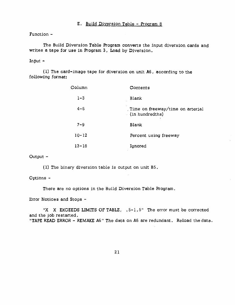
E. Build Diversion Table - Program 8
Function-
The Build Diversion Table Program converts the input diversion cards and writes a tape for use in Program 3 I Load by Diversion.
Input -
( 1) The card-image tape for diversion on unit A6 I according to the following format:
Column
1-3
4-6
7-9
10-12
13-18
Output -
Contents
Blank
. Time on freeway/time on arterial (in hundredths)
Blank
Percent using freeway
Ignored
(1) The binary diversion table is output on unit B5.
Options -
There are no options in the Build Diversion Table Program.
Error Notices and Stops -
11 X X EXCEEDS LIMITS OF TABLE, . 5-l. 511 The error must be corrected and the job restarted. 11 TAPE READ ERROR - REMAKE A6 11 The data on A6 are redundant. Reload the data.
21
Normal Operation -
The program will read all of the trip volume data for a given origin zone and then write the binary record for that zone. This is repeated until the input is exhausted at which time the input and output tapes are rewound and the Control Monitor is called.
Error Notices and Stops -
( 1) NO SWITCH HAS BEEN SET TO SELECT A VOLUME FIELD- The switch card must be supplied to the control monitor so that the internal switch can be set. The next card after the switch card should be the one calling the trip volume program again.
( 2 ) READ ERROR ON INPUT TAPE - Make sure proper tape is mounted on unit A6 and press start to reread.
( 3 ) AN ORIGIN ZONE IS OUT OF SORT - Press start to ignore this record or prepare a new sorted input tape.
( 4 ) ORIGIN ZONE IS MISSING FROM THE INPUT DATA - Program continues.
( 5 ) VOLUME FOR LAST ZONE HAS BEEN WRITTEN. INPUT TAPE OR PARAMETER CARD IN ERROR. A CARD HAS BEEN READ WHOSE A NODE IS GREATER THAN THE LAST ZONE NUMBER SPECIFIED BY THE *PARAM CARD - The Control Monitor is called.
23
Go Format Trees -Program 11
Function-
The Format Trees Program converts selected trees to a format suitable for printing and writes the output on a BCD tape for printing o
Input -
Input to the Format Trees Program is in the form of trees written in the binary format of the tree builder program. This input is read from tape A3 o If an end of file is encountered on A3 before all selected trees are foundo reading is continued on tape A4. A control card is read from the card reader which contains the trees selected to be printed. The format of this card is identical to the one used by Build Trees, Program L
Output-
The output of the Format Trees Program is a series of BCD records on tape AS,
Options -
There are no options in the Format Trees Program.
Normal Operation -
The Format Trees Program reads the control card from the card reader, finds the selected trees c and writes the BCD output.
Error Stops and Notices -
( 1 ) -END OF FILE AT CARD READER- Prepare a control card, ready it in the card reader, and push start to reread.
( 2 ) -INCORRECT CONTROL CARD- Correct card, ready it in the card reader t and push start to rereado
( 3 ) -READ ERROR ON INPUT TAPE- Make sure proper tape is mounted on unit A3 or A4 and push start to reread.
( 4) -END OF PHYSICAL TAPE ON UNIT A 5- Dial in a new output tape and press start to continue o
24
H. Print Link Data - Program 12
Function-
The Print Link Data Program reads the binary network description as prepared by the Build Network Description Program. It then formats the data and writes an output tape for off-line printing.
Input -
The binary network description is read from tape A2. A2 is rewound before and after reading.
Output-
The BCD formatted network is written on tape AS for off-line printing. Tape AS is not rewound by this program.
Options -
There are no options in the Print Link Data Program.
Normal Operation -
In normal operation the Print Link Data Program will read the binary network description tape and begin writing its output on tape AS. When the complete network is formatted 1 the program calls the Control Monitor.
Stops and Error Notices -
( 1 ) -READ ERROR ON THE BINARY NETWORK DESCRIPTION TAPE- Make sure that the proper tape unit is dialed to A2.
( 2 ) -END OF PHYSICAL TAPE ON TAPE AS- Dial in a new output tape.
2S
I. Print Trip Volumes - Program 13
Function-
The Print Trip Volumes Program formats and writes BCD records for printing selected portions of the trip volume tape.
Input-
The input to the Print Trip Volume Program is a binary trip volume tape on unit B2 of the same format as produced by the Build Trip Volumes Program, and a control card read from the card reader. The control card is used to select the trips to be printed and has the same format as the tree select card used by Build Trees, Program 1.
Output-
The Print Trip Volumes Program produces BCD records on tape AS o
Options-
There are no options in the Print Trip Volumes Program.
Normal Operation -
The program scans the trip volume tape for the selected trip tables and writes the formatted trips on the output tape o The trip volume tape is rewound prior to and after reading the selected trips but the output tape is never rewound.
Error Stops and Notices -
( 1 ) -END OF FILE AT CARD READER- Provide control card and press start key to reread o
( 2 ) -ERRCR IN CONTROL CARD- Correct control card, ready card in reader and press start to reread.
( 3 ) -UNABLE TO READ INPUT TAPE B2- Be sure that the correct tape is mounted on unit B2 and push start to reread.
( 4 ) -END OF PHYSICAL TAPE ON UNIT AS- Provide new output tape.
26

J. Fratar Forecast - Program 14
Function-
The Fratar Forecast Program projects a set of present trip volumes to some future set of trip volumes.
-Input -
( 1 ) The present trip volumes in the binary format as produced by the Build Trip Volumes program, The present trips are read from tape B4,
( 2 ) The "B" deck read from tape A3. The format of the "B" deck tape is BCD with one card per physical record.
Columns
1 - 3
4 - 6
7 - 18
19 - 24
Contents
Blank
Zone number
Blank
Growth factors right justified. A decimal point is assumed between columns 22 and 23,
( 3 ) A control card with the following formaL
Columns
1 - 4
5 - 6
7 - 10
11 - 12
Output -
Contents
Blank
Maximum number of iterations, right justified
Blank
Maximum acceptable deviation of growth factors from 1 , 0 (in hundredths) I right justified.
The Fratar Forecast Program produces an expanded trip volume tape wlth the same binary format as the output of the Build Trip Volumes Program. The output will be on tapes B 1, B2 I or B3 as indicated by an on-line message.
Normal Operation -
The normal sequence of operations for the Fratar Forecast Program is as follows~
Phase 1, The program reads the control card, the input tape on 84, _and the input tape on A3 ,
Phase 2, The program begins its iterative process and wntes its expanded trips on Bl, 82, 83, Bl, 82, " .. ,, in successiOn, After the first iteration, the input tapes on A3 and 84 are no longer needed and may be removed, At the conclusion of each iteration, an on-line message prints growth factors and the number of zones having these growth factors thus giving an indication of the rate of closure, When the number of iterations has reached the number in columns 5 thru 6 of the control card, or when there are no zones with growth factors differing from 1, 0 or more than the amount m columns 11 thru 12 of the control card, the program stops to permit disposition of the expanded trip tapes. When the Start key is pressed, the control mom tor is called,
Error Notices and Stops -
Error· notices without stops: ( 1 ) TRIP ENDS AS REPORTED IN THE B DECK AND AS COMPUTED FROM THE TRIP VOLUME TAPE DO NOT CORRESPOND - The computed value is used and the program continues. ( 2 ) EXPANDED TRIPS AS REPORTED DIFFER FROM CALCULATED EXPANDED TRIPS - The computed expansion is used to calculate a growth factor and the program contlnues, ( 3 ) OMISSION OF FUTURE TRIP ENDS AND GROWTH FACTORS FOR A ZONE - The growth factor for this zone is left as zero and the program continues, ( 4 ) IMPROPER ZONE NUMBER- If the zone number of a "B" deck card exceeds the last zone number as entered on the * PARAM card, the ''B" deck card is ignored and the program continues,
Error notices wlth stops~ ( 1 ) READ ERROR ON TAPE A 3 - Push start to read the "B" deck again" ( 2 ) READ ERROR ON B CHANNEL TAPE- Push start to reread. ( 3 ) END OF FILE AT CARD READER - Ready a control card and press start.
28
K. Trip End Summary - Program IS
Function-
The Trip End Summary Program computes from a trip volume file the total numb~r of trips entering each zone, the total number of trips exiting from each zone, the total number of intra zonal trips for each zone, and the sum of these to give the total trip ends for each zone. (Intra zonal trips are counted twice since both ends are in the same zone.) In addition, grand sums are computed of the total trip ends and of the total trip ends excluding the intrazonal trip ends. Other sums computed are the number of zones which trips from a given zone enter, and the number of zones from which trips to a given zone exit.
Input -
The input to the Trip End Summary Program is a trip volume tape on unit B2 of the same format as produced by the Build Trip Volumes Program.
Output-
The output of the Trip End Summary Program is in the form of BCD records written on tape AS for printing.
Options -
There are no options in the Trip End Summary Program.
Normal Operation -
The Trip End Summary Program will read the entire trip volume file and then write its output on AS. The trip volume tape is rewound before and after being read. The BCD output tape is not rewound at any time.
Error Stops and Notices -
( l ) -READ ERROR ON INPUT TAPE B2- Make sure that the proper tape is mounted on unit B2 and press the start key to reread.
( 2 ) -PHYSICAL END OF TAPE ON THE OUTPUT TAPE AS- When tape AS is full, a new output tape should be dialed in.
29
L. Build Spider Trees - Program 16
Function-
Build Spider Trees 1 Program 16 1 operates in the same manner as Program 1, Build T~ees 1 except that the trees are built through zone centroids,
Input -
( 1 ) The network description as built by Program 5 I Build Network Description.
( 2 ) A control card I on-line , specifying the zones for which trees are to be built. The format of this card is described in the Program 1, Build Trees, description.
Output-
The minimum path spider trees are output on tape A3, If more than one reel is needed for the trees, the program switches automatically A4, An on-line message is given if this occurs: 11 BEGAN REEL 2 WITH TREE No,. where N is the first tree on reel 2.
Options -
There are no options in this program.
Normal Operation -
The network description and control card are read and the specified trees are built through zone centroids.
Error Notices and Stops -
,.SUCCESSIVE READ ERRORS ON A2 -NETWORK DESCRIPTION TAPE. PUSH START TO RETRY THIS PROGRAM,. - If the error persists, inspect the tape and/or tape unit. ,. END OF FILE AT CARD READER. PREPARE A TREE SELECT CARD o READY IN READER, PUSH START 11
- A control card specifying the trees to be built must be supplied. 11 TREE SELECT CARD IN ERROR,. Correct the card and restart the program.
30
M. Sum Volumes and Turns - Program 17
Function-
The loaded network is formatted in directional and/or nondirectional form. If directional form is specified, the volumes of each turning movement at each node are given.
Input -
( 1 ) The network description as built by Program 5, Build Network Description. (A2)
( 2 ) The loaded network (81) as built by
Output-
(A ) Load Minimum Paths, Program 2
( B) Load By Diversion, Program 3
Note: The volumes listed for ( B) will be 1/4 of the true volumes.
BCD output is written on AS for printing. This is the information desired from either a directional or nondirectional assignment. A jurisdictional summary of the local, arterial, ramp and freeway vehicle-hours, vehicle-miles and speed is written on AS and printed on-line.
Options -
Primary loaded network factored by internal program factor -
to AM peak if SWS is on or
to PM peak if SW6 is on
Supplementary loaded networks added -
from B3 if SW3 is on and/or
from B4 if SW4 is on
Nondirectional volumes computed if SWl is on. Directional volumes omitted if SW2 is on.
31
Error Notices and Stops -
"END OF TAPE ON AS. DIAL IN NEW OUTPUT TAPE" - Output will be continued when a new tape is readied on AS. "NETWORK HAS TURN TABLE BUT NO DICTIONARY" - The tape built by the load program is incorrect. "DICTIONARY NOT COMPATIBLE WITH PARAMETERS" - Either the network was built "incorrectly, or the parameters are incorrect. "LOADED NETWORK NOT COMPATIBLE WITH PARAMETERS" - Same as preceding. "UNABLE TO READ TAPE Bl" - Inspect tape and unit. "LOADED NETWORKS DO NOT MATCH. UNABLE TO ADD VOLUMES" - An incorrect tape has been mounted on B3 and/or B4. "TURN PARAMETERS IMPROPERLY REPORTED" -An error occurred during the load program.
Normal Operation -The loaded network(s) is (are) read from Bl (B3 o B4) and the formatted
output is written on AS.
32
N. Merge Trip Volume Tapes - Program 19
Function-
The Merge Trip Volumes Program takes two binary trip volume tapes of the forma-t produced by the Build Trip Volumes Program and adds corresponding volumes to produce a single binary trip volume tape.
Input -
The binary trip volumes are read from tapes BS and B6.
Output-
The output is a binary trip volume tape in the same format as that produced by the Build Trip Volumes Program" The output is written on tape B2"
Options -
There are no options in the Merge Trip Volume Tapes Program.
Normal Operation -
The input and output tapes are .rewound at the beginning· of execution. The input tapes are read successively with output being written each time the input tapes are read. At the end of execution 1 the input and output tapes are rewound and the Control Monitor is called.,
Error Notices and Stops -
( 1 ) -RECORDS ON THE TWO INPUT TAPES DO NOT MATCH- The zone numbers on the two records just read from the input tapes are not the same. Press start to reread records.
( 2 ) -READ ERROR ON INPUT TAPE- Make sure the correct tapes are mounted on BS and B6 and press start to reread.
33
0. Trip Volume Compaction - Program 22
Function-
Trip volumes are reduced to one zone from several zones by the Trip Compaction Program.
Input-
( 1 ) Trip volumes as prepared by one of the following programs: (B2)
(A ) Build Trip Volumes, Program 10
( B ) Merge Trip Volumes, Program 19
( C ) Fratar Forecast, Program 14
( 2 ) Zones to be compacted, in the following format: (A3)
Output -
Columns
1 - 6
7-12, 13-18 ... ••• 67-72
Information
New zone number (if blank, continuation of last new zone number card) .
Old zones to be compacted into the new zone. If more than 11 fields are needed, the zones may be continued on the next card.
Trip Volumes in the new form are output on A4.
Error Notices and Stops -
Tape Error Halts -
REDUNDANT ZONE EQUIVALENCE TABLE TAPE (A6). REDUNDANT TRIP VOLUME OUTPUT TAPE (A4). REDUNDANT TRIP VOLUME INPUT TAPE (B2).
Zone Equivalence Table Errors -
NEW ZONE NUMBER X OCCURS HERE N TIMES . NEW ZONE NUMBER X DOES NOT OCCUR. OLD ZONE NUMBER X OCCURS HERE N TIMES.
34
OLD ZONE NUMBER X DOES NOT OCCUR. OLD ZONE NUMBER X OUT OF SEQUENCE WITHIN NEW ZONE NUMBER Y (this is not a fatal error-program proceeds- when started) •
Normal Operation -
The zone equivalence table is built and checked before the volumes are compacted.
Note-
The parameter card must designate the last zone number of the old zones to be completed.
35
P. Format Trip Trac.es - Program 50 ·
Function-
Trip Traces are written in either complete or destructive form for zones specified to all other zones.
Input -
( 1 ) Trees as built by Program 1, Build Trees. (A3}
( 2 ) Control card to be read on-line specifying· the trees to be formatted. A ·description of this card is to be found in the description of Program 1 s
Build Trees.
Output-
Trip traces are BCD output on AS.
Options -
If switch 1 is on, the traces will be destructive c
Error Notices and Stops -
"TRACE TOO LONG. "PRESS START TO CONTINUE" - A trace in excess of 300 links has been encountered. "ERROR ON TREE TAPE. DIAL IN NEW TAPE AND PRESS START 11
- The trees specified are on another tree tape 1 or an incorrect card was supplied. "READ ERROR ON TREE TAPE. PUSH START TO RETRY" "END OF TAPE ON AS. DIAL IN A NEW OUTPUT TAPE. PUSH START TO CONTINUE" Another reel is needed for output. "BAD TREE SELECTION CARD. CORRECT AND PRESS START"
Normal Operation -
Trees are formatted on AS for printing.
36

Q. Plot Network Description - Program 23
Function -
The Plot Network Description Program writes a decimal tape to be used on an IBM 1401 digital computer in conjunction with a California Computer Products Model 565-Digital Incremental Plotter to produce a network map in directional or rondirectional form.
Input -
The inputs to the Network Description Plot Program are:
1. Network description tape as built by the Build Network Program (Program 5) on A2.
2. Library of node locations, a card image tape on B3, in the following format:
Column Information
l - 6 Node number
7 -12 Node X coordinate (abscissa)
13 -18 Node Y coordinate (ordinate) (AU numbers are right justified.)
3, Control Cards
A. If more than one plot is to be made, a number card should be used.
Column
1 - 6
Information
NUMBER (required)
Number of plots to be made, right justified.
B. A type 1 card is required for each plot desire.
Column
1 - 6
37
Information
If a directional plot, DIRECT If a nondirectional plot, this field is blank.
7 - 12
13 -18
24
36
42
48
54
Number of strips to be plotted; right justified ..
Number of colors to be plotted, right justified.
If colors are specified; C,
I{ street type selection 1 N.
If the network description used on the previous plot may be used on this plot 8 * &
If this is the first plot or if a different network is to be used, blank.
If the library of location coordinates used on the previous plot may be used on this plot u *.
If a new librar;y is to be used or if this is the first plot, blank ..
'. 1 (required)
Co If column 2 4 of card type 1 contains .q C; a type 2 card is required .. Colors for each street type are specified by placing the color desired in the following field format. This word is used in a message to the 1401 operator plotting the tape.
Column Information
1 - 6 Color 1
7 - 12 Color 2
13 - 18 Color 3
54 2 (required)
For example, red may be color 1, blue I color 2, etc. The colors available for plotting use are red; green, blue 1 and black 0
D. If column 36 of card type 1 contains a N, a type 4 card is used for street type selection. This is the specification of street types, to be plotted in different colors.
38
Column Information
6 Street type to be plotted with color 1
12 Street type to be plotted with color 2
18 Street type to be plotted with color 3
54 4 (required)
The street types are specified as follows:
Arterials A
Locals L
Freeways F
Output-
A decimal tape is written on unit A4. This tape must be interpreted by a 1401 plot interpreter program (reference - Traffic Assignment Plot Systems -publication.)
Options -
Options are taken by control cards described above&
Normal Operation -
The library of node locations is read simultaneously with the network description recorde If no more network description plots are to be made, these two tapes may be removed when they are rewound •. The plot records are written on A4. Tape B5 is used to hold intermediate volumes.
The output tape is not rewound at the beginning or at the end of a job. This enables a plot of trees or of the loaded network to be made at a later time using the same tape.
When each plot is complete, if more than one plot is specified1 the next control card set is read.
Error Notices and Halts -
All error halts which occur print an on-line error message to the .operator.
39
1. -CONTROL CARDS MISSING OR OUT OF ORDER- To retry 6 correct cards and load tape. To delete ploto press starto Possible causes for this message are:
A. Card reader end of file
B& Type 1 card missing (or mispunched)
C. Type 2 card missing (or mispunched} when type 1 card specified that colors were to be specified.
D. Type 4 card missing (or mispunched) when the type 1 card specified the street type selection option.
2. -READ (WRITE) ERROR UNIT XX. PUSH START TO RETRY- This message occurs when a permanent read (write) error has been established. Push start to retry the operation.
3. -END OF TAPE A4. MOUNT A NEW A4 1 AND PRESS START- When tape A4 has reached an end of tape mark 4 an end of file is written on the tape 4
and the computer halts for a new tape to be mounted.
4. -THE FOLLOWING NODES ARE UNDEFINED- This message does not cause a computer halt. If links in the network description can not be drawn because a node was not defined on the library tape (B3}, this message is given at the end of the plot program.
40

R. Plot Loaded Network - Program 24
Function-
The Plot Loaded Network Program writes a decimal tape to be used with a California Computer Products Model 565 Digital Incremental Plotter through an IBM 1401 digital computer.
Input -
The inputs to the Plot Loaded Network Program are
1. Loaded network tape I as built by the Load Minimum Paths Program on B 1 •
2. Library of node locations (card image tape) on 83, in the following format:
Column
1 - 6
7 - 12
13 - 18
3. Control cards as follows:
Information
Node number
Node x coordinate (abscissa)
Node y coordinate (ordinate) (all numbers right justified)
A. If more than one plot is to be made, a number card should be used.
Column
1 - 6
7 - 12
Information
NUMBER (required)
Number of plots to be made I right justified.
B. A type 1 card is required for all plots o This card specifies which options are to be taken for each plot o
Column
1 - 6
ttl
Information
If a directional plot is to be made, DIRECT.
7 - 12
13 - 18
24
30
36
42
48
54
If a nondirectional plot is to be made blank.
Number of strips for this plot
Number of colors for this plot.
If colors are to be specifiedc C. If colors are not specified, blank.
If volume ranges are to be specified, V. If no volume range selection, blank.
If street types will be specified, N. If no street type specification_. blank.
If the loaded network used on the previous plot may be used a gains*. If this is the first plot, or if a different loaded network is desired, blank.
If the library used on the previous plot is to be used on this plot·' *. If this is the first plot, or if a different library is to be used, blank.
1 (required}
c. A type 2 card is needed if column 24 of the type 1 card contains a C •
Column Information
1 - 6 Color 1
7 - 12 Color 2
13 - 18 Color 3
19- 24 Color 4
54 2 (require d)
Color 1, color 2, color 3, and color 4 are the words which will be used in a message to the 1401 operator who is plotting the tape.
42

D. Volume range selection may be made if column 30 of card type 1 contains a V. This selection is made by a type 3 card.
Column
1- 6
7-12
13-18
19-24
25-30
31-36
37-42
43-48
54
Information
Minimum and
Maximum volumes to be plotted in color 1.
Minimum and
Maximum volume to be plotted in 'color 2.
Minimum and
Maximum volume to be plotted in color 3.
Minimum and
Maximum volume to be plotted in color 4.
3 (require d)
E. If column 36 of card type l contains N, a type 4 card must be supplied.
Column Information
6 Street type to plot in color 1
12 Street type to plot in color 2
18 Street type to plot in color 3
24 Street type to plot in color 4
54 4 (required)
The street types are selected as follows:
A Arterial
L Local
F Freeway
43
Output-
A decimal tape is written on unit A4. This tape must be interpreted by a 1401 plot program (see the- Texas A and M University Plot Systems-reference publication).
Optiops -
Options are taken by control cards described above.
Normal Operation -
See the Normal Operation section of Program 23 1 Plot Network Description" This programs operates in a like manner.
Error Notices -
All error notices which may appear in Program 23 may appear in this program. An additional nonhalt message is
THE FOLLOWING UNKS DO NOT HAVE A CORRESPONDING .OPPOSITE UNK
When a nondirectiona 1 plot has been specified and the error condition that node X has a volume to node Y but node Y does not have a record of a link to node X 1 this message is printed on-line. The volume may be zero. This.,is an error only when the link is not acknowledged by the node Y records~ An additional cause for the plot control cards missing or out of order message is failure to supply a type 3 card when the type 1 card selects the volume range selection option.
44
S. Plot Trees - Program 2 5
Function-
The Tree Plot Program writes a decimal tape which may be used wi.th an lBM 1401 computer in conjunction with a California Computer Products Model 565 Digital Incremental Plotter to draw the network trees specified"
Input -
Required input to the Plot Trees Program is~
1, Tree tape as built by Program 1 _ Build Trees,
2, Library of node locaUon coordinates on tape B3 (a card image tape in the following format)
Column
1 6
7 - 12
13 - 18
3, Control cards as follows
Inform au on
Node number
Node X coordlnate (abscissa)
Node Y coordmate (oramate) (all numbers are nght justlfJed)
A. General mformatwn on all trees is specified by a Type T card-
Column
1 6
7 - 12
54
Information
Number of stnps
Color to be used in plctting the trees
T (required)
B 0 A centroi.d selection card designates the trees to be plotted 0 It is in the same form as described by the Build Trees, Format Trees, or Format Tree Trace Programs, Refer to those sections for the centroid selection card format,
45
Output-
A decimal tape is written on unit A4. This tape must be interpreted by a 1401 plot program (see the Texas A and M University Plot System publication).
-Options-
Options are taken by control cards described above.
Normal Operation -
After the type T and centroid selection cards have been read! the library of node locations is read. This tape may be removed after it is rewound, The trees specified by the centroid selection card are then found on the binary tree tape and a decimal tape is written on A4. When all trees have been plotted, the tree tape is rewound.
Error Notices and Halts -
1. Without computer halts.
A. END OF TAPE A3 ENCOUNTERED BEFORE TREE NNNN WAS FOUNDIncorrect centroid selection card possible. End of run assumed.
B. THE FOLLOWING NODES ARE UNDEFINED - If a tree required the location of a node which was not on the library of node locations tape 1 the node is listed on the on-line printer.
2. With computer halts
A. CONTROL CARDS MISSING OR OUT OF ORDER - To retry, correct cards and load tape. To delete plot I press start. Possible causes are:
1 . Card reader end of file.
2. Type T card missing or mispunched.
B. PERMANENT READ (WRITE) ERROR ON UNIT XX - Inspect tape and unit.
46
T. Plot Central Business District - Program 2 6
Function-
Since the volumes written on a central business district plot are indistinct because of link density, this program permits a plot of the CBD with volumes written on all freeway and arterial links.
Input-
( 1 ) The node location library on unit B3 .
( 2 ) The loaded network on unit B1.
( 3 ) Control card(s) read on line.
Column
1- 6
(optional) 7-12
(necessary) 1- 6
7-12
13-18
19-24
25-30
31-36
37-42
54
Output-
Plot tape on A4 .
Options -
Information
"NUMBER"
Number of CBD'S to be plotted at this time, if more than 1.
If a directional plot, "DIRECT".
Number of strips
Color to be used, i.e. , RED
Minimum X value to plot
Maximum X value to plot
Minimum Y value to plot
Maximum Y value to plot
Q (necessary)
Options are exercised by the input control card.
47
Error Notices and Stops -
Tape Messages
"READ/WRITE ERROR ON UNIT XX. PRESS START TO RETRY. "
"THE FOLLOWING NODES WERE UNDEFINED". Nodes which were needed for the plot, but were undefined, are listed.
"INCORRECT CONTROL CARD". Replace and correct control card (C in column 54).
Normal Operation -
The loaded network and node locations are read. After checking for a "NUMBER" card the control card for each CBD is read and the plots are made.
48

U. Plot Loaded Network With Volumes - Program 27
Function-
This program plots the loaqed network in the same manner I and with the same options 1 as Program 24, Plot Loaded Network. According to a switch setting, volumes of traffic will be written on freeway and/or arterial links. The options allowed by control cards are the same as for Program 24.
Input -
Same as Program 24
Output -
Same as Program 24
Options -
Switch 1 on - write arterial volumes
Switch 2 on - write freeway volumes
Normal Operation -
After plotting the network I volumes are written on each link of the network (art, and/or fwy).
Additional Notes On Output Tape Handling -
The plot program writes an identification word at the end of all plots. For this reason 1 do not end-file the plot tape; this would erase the identification tape word.
49
IX. ON-LINE PRINT COMMENTS
Build Trees Program - Program 1
CONTROL CARD READ ON-LINE
NETWORK DESCRIPTION READ FROM TAPE A2
TREES WRITTEN ON A3 AND A4 (BINARY)
Load Minimum Paths Directional - Program 2
NETWORK DESCRIPTION READ FROM TAPE A2
TREES READ FROM TAPE A3 TO A4
TRIP VOLUMES READ FROM TAPE B2
LOADED NETWORK WRITTEN ON TAPE B 1
TRIP LENGTH DISTRIBUTION TABLES WRITTEN ON TAPE BS
CONTROL CARDS READ ON-LINE
( 1 ) ZONES TO BE LOADED
( 2 ) DESTINATIONS TO BE LOADED
( 3 ) LIMITS FOR TRIP LENGTH DISTRIBUTION LOADING AND
EXTERNAL STATION NUMBER
Load by Diversion Directional Program 3
INPUT - NETWORK DESCRIPTION READ FROM TAPE A2
FREEWAY TREES READ FROM TAPES A3 AND A4
ARTERIAL TREES READ FROM TAPES B3 AND B4
TRIP VOLUMES READ FROM TAPE B2
DIVERSION CURVE READ FROM TAPE 5
50
OUTPUT- LOADED NETWORK WRITTEN ON TAPE Bl
TRIP LENGTH DISTRIBUTION TABLES WRITTEN ON TAPE B5
CONTROL CARDS READ ON-LINE
( 1 ) ZONES TO BE LOADED
( 2 ) LIMITS FOR TRIP LENGTH DISTRIBUTION LOADING
OPTIONS - SW 4
UP- USE ASSEMBLED DIVERSION CURVE (55 PER CENT)
DOWN - READ DIVERSION CURVE FROM TAPE B5
Build Network Description - Program 5
INPUT - LINK DATA ON TAPE A6
OUTPUT - MEMORY A WRITTEN AS ONE RECORD ON TAPE A2
ERRORS PRINTED ON-LINE
OPTIONS-INPUT FIELD 1 SW 1 ON
FIELD 2 SW 2 ON
PRINT ONE-WAY LINKS IF SW 4 ON
FREEWAY LINKS AT FULL TIME IF SW 5 ON
EXCLUDE FREEWAY LINKS IF SW 6 ON
Build Trip Volumes - Program 10
INPUT - BCD ON TAPE A6
OUTPUT- BINARY OUTPUT ON TAPE 82
TWO REELS OF INPUT IF SW 6 ON
TRIPS TO BE READ SELECTED AS FOLLOWS
SW 1 ON-- READ COLUMNS 7 THRU 12
SW 2 ON -- READ COLUMNS 13 THRU 18
SW 3 ON -- READ COLUMNS 19 THRU 24
51
Format Trees - Program 11
TREE FILE READ FROM TAPE A3 AND THEN A4
OUTPUT WRITTEN ON TAPE AS
CONTROL CARD READ ON-LINE
Print Link Data - Program 12
INPUT - NETWORK DESCRIPTION READ FROM TAPE A2
OUTPUT- OUTPUT WRITTEN ON TAPE AS
Print Trip Volumes - Program 13
INPUT - TRIP VOLUMES READ FROM TAPE B2 (BINARY)
OUTPUT-BCD OUTPUT ON TAPE AS
Fratar Forecast Program - Program 14
INPUT - TRIP VOLUMES (BINARY) READ FROM TAPE B4
OUTPUT-EXPANDED VOLUMES WRITTEN ON TAPES B1 8 B2u B3, Bl, B2 8
NOTES- LAST EXPANDED TRIP VOLUME TAPE IS THE FORECASTED TRIP
VOLUMES
Trip End Summary - Program 15
INPUT - TRIP VOLUMES (BINARY) READ FROM TAPE B2
OUTPUT--BCD TAPE FOR PRINTING WRITTEN ON'.TAPE AS
52
. " "
PUBLICATIONS
Project 2-8-63-60 Traffic Assignment
1. Research Report 60-11 "Texas A&M Traffic Assignment Link Data Editor for IBM 1401 Data Processing System" by Glenn N. Williams.
2. Research Report 60-2 1 "Texas A&M Traffic Assignment Edit Print Trip Volumes for IBM 1401 Data Processing System 11 by William F. Pry.
3. Research Report 60-3 I 11 Traffic Assignment Plot Systems for IBM 1401 and IBM 709/90/94 Data Processing Systems" by William F. Pry.
4. Research Report 60-41 11 Utilization of Computer Plotting in Traffic Assignment Analysis 11 by William F. Pry and Charles Pinnell.
5. Research Report 60-5 I .. Operating System Manual for Revised Texas Traffic Assignment System,. by Charles W. Blumentritt.
53