Embed Size (px)
Citation preview

1 | Operating Process for Access to High Voltage Apparatus | CONTROLLED DOCUMENT ____________________________________
Summary
This procedure supports the Power System Safety Rules and its requirements assembled under the Operation of High Voltage Switchgear - Categories 5, 6 and 7.
It applies to the Operation of High Voltage Air Insulated Switchgear and Gas Insulated Switchgear for the purpose of issuing an Access Authority and subsequent Restoration.
This document also provides general guidance and background information related to the operation of various types of high voltage apparatus and guidance material related to use of a High Voltage Preparation and Restoration Instruction
Revision no: 7 TRIM No: D2004/7794 Approval/ Review Date:
25 November 2021
Business function:
Manage Health, Safety and Environment Document type:
Procedure
Lumea circulation:
Yes ☒ No ☐
Process owner: Head of HSE
Author: Kitchener Morris, PSSR Manager
EM approval: Yes ☐ No ☒
Reviewers: Daniel Palombi, Senior HSE Partner- Electrical Safety
Geoff Cook, Control Room Manager
David Moore, Training Delivery Team Leader
Nicol Joubert, Senior HSE Manager
Approver: Krista-Lee Fogarty, Head of HSE
A printed copy of this document may not be the current version. Please refer to the Wire to verify the
current version.
Operating Process for Access to High Voltage Apparatus
CONTROLLED DOCUMENT
2 | Operating Process for Access to High Voltage Apparatus | CONTROLLED DOCUMENT ____________________________________
Contents
1. Overview...................................................................................................................................................... 5
1.1. Purpose ................................................................................................................................................. 5
1.2. Reference Documents ........................................................................................................................... 5
1.3. Scope..................................................................................................................................................... 5
1.4. Accountability ........................................................................................................................................ 5
1.5. Document Location ............................................................................................................................... 6
2. Operating Requirements ........................................................................................................................... 6
2.1. Introduction ............................................................................................................................................ 6
2.2. Requirements to make high voltage apparatus safe to work on or near .............................................. 7
2.3. Use of High Voltage Preparation and Restoration Instructions ............................................................ 7
2.3.1. Overview ......................................................................................................................................... 7
2.3.2. Communication between an Authorised Person and Controller .................................................... 7
2.3.3. Preparation for Use of a HVPRI ..................................................................................................... 8
2.3.4. Execution of the HVPRI Steps ..................................................................................................... 10
2.4. Switching Focus .................................................................................................................................. 11
3. Generic Switching Process ..................................................................................................................... 12
3.1. On arrival to site .................................................................................................................................. 13
3.2. Preparation .......................................................................................................................................... 14
3.2.1. De-energising or Offload - Operation of Circuit Breaker .............................................................. 14
3.2.2. De-energising or Offload – Confirm Operation of Circuit Breaker ............................................... 15
3.2.3. Isolation - Operation of Motorised Disconnector .......................................................................... 15
3.2.4. Isolation - Operation of Manual Disconnector .............................................................................. 16
3.2.5. Isolation – Voltage Transformer ................................................................................................... 17
3.2.6. Isolation – 415V Transformer connections .................................................................................. 18
3.2.7. Earthing - Preparation .................................................................................................................. 19
3.2.8. Earthing - Earth Switch Manual .................................................................................................... 20
3.2.9. Earthing - Earth Switch Motorised ................................................................................................ 21
3.2.10. Earthing - Portable Earths .......................................................................................................... 22
3.2.11. Earthing for inadvertent re-energisation from the tertiary connections. ..................................... 23
3.2.12. Earthing – Voltage Transformer Secondaries ............................................................................ 23
3.2.13. Shorting and Earthing Busbar Protection CT Contributions ...................................................... 25
3.3. Access Authority Issue and Cancellation ............................................................................................ 26
3.4. Restoration .......................................................................................................................................... 26
3.4.1. Removal of Earthing - Earth Switch ............................................................................................. 27
3.4.2. Removal of Earthing - Portable Earths ......................................................................................... 27

3 | Operating Process for Access to High Voltage Apparatus | CONTROLLED DOCUMENT ____________________________________
3.4.3. Removal of Earthing – VT Secondaries ....................................................................................... 28
3.4.4. Removal of Earthing and Shorting of BBP CT contributions ....................................................... 28
3.4.5. Return to Service .......................................................................................................................... 29
4. Operating Gas Insulated Switchgear (GIS) ........................................................................................... 32
4.1. Power System Safety Rules Requirements ........................................................................................ 32
4.2. General Requirements ........................................................................................................................ 32
4.2.1. Electrical and Mechanical Safety features ................................................................................... 32
4.2.2. Defeating of Interlocks during Operational Switching .................................................................. 32
4.2.3. Defeating of Interlocks during work under an Access Authority .................................................. 32
4.2.4. Preparation of Switching Instructions ........................................................................................... 32
4.2.5. Order of Switching Operations ..................................................................................................... 33
4.3. Making GIS Equipment Safe for Work using Remote Operation........................................................ 33
4.3.1. Isolation ........................................................................................................................................ 33
4.3.2. Earthing ........................................................................................................................................ 33
4.3.3. Securing the Isolation and Earthing ............................................................................................. 33
4.4. Making GIS Equipment Safe to Work where Local operation is required .......................................... 33
4.4.1. Isolation ........................................................................................................................................ 33
4.4.2. Earthing ........................................................................................................................................ 33
5. Site log and incidents .............................................................................................................................. 34
5.1. Operating functions that are not steps in a PRI .................................................................................. 34
5.2. Recording of Site Incidents ................................................................................................................. 34
6. Tags and Labels ....................................................................................................................................... 34
6.1. Do Not Operate Tags and Warning Tags ........................................................................................... 34
6.1.1. Obsolete Do Not Operate Tags or Warning Tags ........................................................................ 35
6.2. Control Inhibit Tags ............................................................................................................................. 35
7. Locking Of High Voltage Switchgear ..................................................................................................... 35
8. General Operating Principles ................................................................................................................. 36
8.1. Circuit Breakers ................................................................................................................................... 36
8.1.1. Operating requirements for circuit breakers ................................................................................. 36
8.1.2. General limitations - Circuit breakers ........................................................................................... 37
8.2. High Voltage Capacitors and Reactors ............................................................................................... 38
8.2.1. High Voltage Power Capacitors ................................................................................................... 38
8.2.2. HV Capacitor Earthing .................................................................................................................. 39
8.2.3. High Voltage Power Reactors ...................................................................................................... 39
8.2.4. Operating requirements for control schemes ............................................................................... 39
8.3. Disconnectors and Similar Equipment ................................................................................................ 40

4 | Operating Process for Access to High Voltage Apparatus | CONTROLLED DOCUMENT ____________________________________
8.3.1. Operation of disconnectors .......................................................................................................... 41
8.3.2. By-pass switches .......................................................................................................................... 41
8.3.3. Bus selector disconnectors .......................................................................................................... 41
8.4. Earthing ............................................................................................................................................... 42
8.4.1. Proving de-energised ................................................................................................................... 42
8.4.2. Portable earths ............................................................................................................................. 43
8.5. Fault Earth Switches ........................................................................................................................... 43
8.5.1. Operating requirements for fault earth switches .......................................................................... 43
8.5.2. Post fault checks .......................................................................................................................... 43
9. Change history ......................................................................................................................................... 43
10. Implementation ....................................................................................................................................... 44
11. Monitoring and Review .......................................................................................................................... 44
12. Attachments ............................................................................................................................................ 45

5 | Operating Process for Access to High Voltage Apparatus | CONTROLLED DOCUMENT ____________________________________
1. Overview
1.1. Purpose
This procedure supports the Power System Safety Rules and its requirements assembled under the
Operation of High Voltage Switchgear - Categories 5, 6 and 7.
1.2. Reference Documents
Power System Safety Rules
Access for Work on High Voltage Substation Apparatus
Access for Work on High Voltage Overhead Lines
Access for Work on High Voltage Transmission Cables
Proving High Voltage Conductors De-energised
Portable Earthing of High Voltage Conductors
High Voltage Operating Rods
Safe Work Practices on LV/MECH Apparatus
OM973 – HV Preparation and Restoration Instructions
1.3. Scope
This procedure applies to the operation of high voltage switchgear for the purpose of issuing an Access
Authority and subsequent restoration. This document also provides general guidance and background
information related to the operation of various types of high voltage apparatus.
1.4. Accountability
Responsible person Responsibility
Head of HSE Maintenance and ownership of this procedure
Training Manager Implementation of training programs associated this procedure
Authorised persons Comply with this procedure

6 | Operating Process for Access to High Voltage Apparatus | CONTROLLED DOCUMENT ____________________________________
1.5. Document Location
Block diagram showing relationship to other PSSR documents:
Operating Process for Access to HV Apparatus
Power System Safety Rules
Category 5 Category 6 Category 7
Access for Work
on HV Substation
Apparatus
Safe Work
Practices on HV
Overhead Lines
Safe Work
Practices on HV
Cables
Supporting Documentation
Pro
ce
du
res
Access for Work
on HV Overhead
Lines
Access for Work
on HV
Transmission
Cables
Wo
rk
Ins
truc
tion
s
Safe Work
Practices on HV
Substation
Apparatus
Requests for
Access
Category 2
2. Operating Requirements
2.1. Introduction
The operation of high voltage switchgear is required to ensure that safe conditions are established prior to
the issuing of an Access Authority on high voltage apparatus including overhead lines and cables.
The sections within this procedure cover:
The general operating process
The generic sequence required to safely prepare high voltage apparatus ready for the issue of an
Access Authority and the generic restoration sequence required after cancellation of an Access
Authority
Requirements for making Gas Insulated Switchgear safe for work
General operating requirements for logging, tagging and locking of high voltage switchgear.
This procedure should be read in conjunction with procedures for access to high voltage apparatus which
cover the issue and cancellation of Access Authorities:
Access for Work on High Voltage Substation Apparatus;
Access for Work on High Voltage Overhead Lines; and
Access for Work on High Voltage Transmission Cables.
To access these procedures, refer to the Wire PSSR Page or Power System Safety Rules @ Transgrid

7 | Operating Process for Access to High Voltage Apparatus | CONTROLLED DOCUMENT ____________________________________
2.2. Requirements to make high voltage apparatus safe to work on or near
High voltage apparatus is made ready for work by use of a High Voltage Preparation and Restoration
Instruction (HVPRI). The HVPRI is used to ensure safe working conditions are in place before any Access
Authorities are issued and work commences. The HVPRI will include specific instructions for:
Isolation of the high voltage apparatus including locking open of points of isolation and affixing tags
where relevant. These points of isolation shall include low voltage sources, which can cause the
conductors to become live at high voltage.
Verifying that the high voltage conductors have been de-energised;
Earthing of the high voltage conductors and,
Taking Local Safety Precautions.
Note: Local Safety Precautions for isolation of hazardous low voltage and mechanical apparatus are
detailed in a Low Voltage or Mechanical Preparation and Restoration Instruction (LVMPRI).
2.3. Use of High Voltage Preparation and Restoration Instructions
2.3.1. Overview
When planning and performing a High Voltage Preparation & Restoration Instruction (HVPRI) the safety of
persons in the electrical station, including the authorised person performing the switching, is of the utmost
importance, as is the prevention of damage to high voltage equipment and maintaining reliability of supply.
HVPRIs shall be prepared in accordance with OM 973 and shall only be prepared and checked by persons
authorised Category 2.3.
HVPRIs shall only be carried out by persons authorised:
Operate LV/MECH Apparatus – Category 4.3;
Operate HV Air insulated switchgear – Categories 5.5, 6.5; and
Operate HV Gas insulated switchgear – Category 5.6.
When an Access Authority is to be issued in accordance with an approved Request for Access (RFA), the
required HVPRI shall be carried out by an appropriately authorised person.
A written, checked HVPRI issued to the Authorised Person assigned to carry out the switching shall be
followed.
2.3.2. Communication between an Authorised Person and Controller
Oral communications regarding a HVPRI must be precise and accurate, otherwise errors and inaccuracies
might develop in the transmission and receipt of operating messages and lead to incorrect switching.
Where clear transmission of instructions is prevented by poor quality communication channels, alternative
methods shall be pursued by the controller and the authorised person until a method is found that allows
clear communication.
Where a step of a HVPRI requires advice to be given or accepted, the Controller and the Authorised
Person shall quote the step number and clearly state the specific action that is to be undertaken or that has
been completed.
The Controller shall approve or request only one group of switching steps to be carried out at one time by
the authorised person.

8 | Operating Process for Access to High Voltage Apparatus | CONTROLLED DOCUMENT ____________________________________
If the Controller loses contact with the Authorised Person at any time (e.g. there is no ring back within a
reasonable period after the estimated time for a series of switching steps), then an attempt shall be made
to contact the Authorised Person. If the call is not answered, emergency action shall be initiated to verify
that the authorised person has not been injured.
An example of correct communication protocols is provided in Appendix A.
2.3.3. Preparation for Use of a HVPRI
2.3.3.1. Field copies delivered by electronic transmission
Field copies of HVPRIs are sent to the locations where they are to be used by using the local printer,
facsimile transmission (FAX) or may be used where a printer is not available.
2.3.3.2. Checking of field copy of HVPRI before use
The authorised person carrying out the switching shall:
a. Check completeness and correct collation of the HVPRI just before use, ensuring that all pages are
present and in the correct order;
b. Check that the HVPRI to be used matches the task to be performed;
c. Review the HVPRI ensuring the steps make sense for the work to be performed and can be safely
performed by the switcher; and
d. When issue of an Access Authority is involved, that the copy of the Request for Access (RFA) held
by the working party exactly matches the RFA attached to the HVPRI and referred to in it. If there
is a discrepancy in this regard, or if it is considered that there is a discrepancy between the safety
conditions for the working party required by the Power System Safety Rules and those provided by
the HVPRI, the matter shall be referred to the controller for resolution.
Any issues or discrepancies detected or suspected must be resolved before the switching commences.
2.3.3.3. Amendments to a checked HVPRI
Minor changes to a HVPRI are permitted based on consultation between the switcher and the Controller.
The field switcher may only amend the field copy of the HVPRI after approval has been given by The
Controller. All deleted steps on the HVPRI must be crossed out with pen, made completely illegible and
marked as deleted. The amendments section at the bottom of the page must be completed, and a written
note provided to record the details of why the amendment was made, for future referencing.

9 | Operating Process for Access to High Voltage Apparatus | CONTROLLED DOCUMENT ____________________________________
Example of an amended HVPRI:
2.3.3.4. Preamble Discussion
To confirm that the correct HVPRI is being used, the authorised person shall identify all three of the
following features with the Controller prior to commencing switching:
Its unique number
The equipment specified in the heading
The number of pages in the switching.
Before commencing a switching operation, the Controller shall spend a few moments discussing with the
Authorised Person the objectives of the switching, plus other significant operational factors. This might
include:
Whether any customer load might be left radial by the outage
Any similar work that may be planned for the same day
Whether the equipment being switched has already been off-loaded from its remote end (so no current
flow would be expected)
Significant prevailing weather conditions
Any other information that may be of assistance to the authorised person in discharging their duties.
This preamble shall be kept brief, but shall be sufficient to ensure that all parties involved with the switching
have a “big picture” overview. If the Authorised Person is still unclear, further information shall be
requested before commencing switching.

10 | Operating Process for Access to High Voltage Apparatus | CONTROLLED DOCUMENT ___________________________________
2.3.4. Execution of the HVPRI Steps
2.3.4.1. General Requirements:
(a) The Authorised Person and the Controller shall ensure they have access to the HVPRI at all times.
(b) The steps must be executed in order, unless agreed between the Authorised Person and the
Controller.
(c) If any errors are found in the course of the switching, these shall be immediately reported to the
Network Control Manager by either the Controller or Authorised Person and amended as required.
(d) If any of the HVPRI steps are not or cannot be completed in the anticipated manner, the Authorised
Person and the Controller shall discuss this before deciding whether to proceed. Steps shall not be
repeated without this discussion taking place.
(e) Before commencing each agreed group of steps, the Authorised Person shall discuss with the
Controller the probable duration. By doing this,
- The Controller will be able to assess whether the switching is proceeding according to plan
- The Controller will not disturb the Authorised Person unnecessarily by requesting the status of
progress
- If the Authorised Person is overdue, the Controller will know when it is an appropriate time to raise
the alarm
In the event that the Authorised Person considers that they cannot perform the HVPRI or groups of
steps in the HVPRI in the estimated time they shall advise the Controller.
(f) All HVPRI steps shall be carried out carefully and without undue haste. All staff involved in the
switching process need to be aware of potential and actual distractions and interruptions and adopt
strategies to avoid these affecting their switching performance.
(g) If at any stage either party (Authorised Person or Controller) is not happy to proceed, then switching
shall be suspended until the problem is resolved. This could be for safety, operational or personal
factors all of which are acceptable reasons for suspending the switching and preferable to incurring a
switching error.
(h) Initiating and blocking steps are required to have the time noted on the HVPRI.
Steps shall be crossed off by drawing a non-obliterating line through the whole step and only after all the
required actions are completed. In the case of a multi-action step the individual action parts may be
crossed off as each is completed ahead of crossing off the whole step.
2.3.4.2. Actions to be Taken by Authorised Person (8 Step Method)
At each step of the HVPRI the Authorised Person shall apply a disciplined approach to ensuring the HVPRI
step is completed correctly. The following 8-step method is suitable:
1. Read the HVPRI step
2. Take the HVPRI to the point of operation
3. Check the equipment description against the HVPRI
4. Prepare to perform the required actions
5. Check again the equipment description and required actions against the HVPRI
6. Perform the required actions
7. Check device has operated and all actions completed correctly
8. Cross off the step in the HVPRI
11 | Operating Process for Access to High Voltage Apparatus | CONTROLLED DOCUMENT ___________________________________
On completion of the last step of the HVPRI, the Authorised Person will advise the Controller accordingly
and place the completed HVPRI in the on-site file, where it is to be retained for 12 months.
2.3.4.3. Changing Switchers
Where a second Authorised Person is to take over switching, the first Authorised Person shall complete the
HVPRI to the next suitable blocking step so that the second Authorised Person has a clear and logical
starting point. Before continuing, the Authorised Person taking over switching shall review the actions
taken in previous steps and ensure that they are familiar with all relevant conditions existing at the time of
taking over switching.
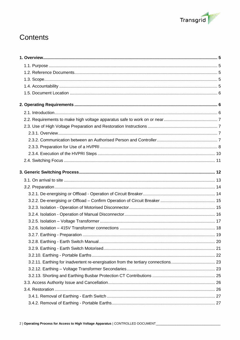
2.4. Switching Focus
Switching is a safety critical activity. For the Authorised Person, those
around them and the work group who are relying on the isolations and
earthing being performed.
Persons authorised PSSR Category 5.5, 5.6 or 6.5 carrying out HV switching
duties must ensure they are completely focused on the switching tasks they
are required to perform. They must ensure they adhere to the following
requirements:
Always perform the IMSAFER check prior to commencing switching. Use
this time to focus on the switching and eliminate other distractions and
tasks from their mind.
Always wear the pink “Switching in Progress” vest when completing
switching steps.
Only perform the switching activity. Never perform another task at the
same time.
Review the switching before you commence to ensure you understand
the steps you are to perform and ensure they make sense in relation to the work to be performed.
Prepare yourself with the equipment (tools, tags, etc.) you will need to complete the switching.
Always use the 8 step method to complete every step. Every step in the switching is important.
Ensure you use correct communication protocols with the System Operator. Speak clearly and
purposefully and read back instructions.
If you do become distracted, stop, take the time to reassess where you were up to and what you were
doing, prior to recommencing the switching activity, never rush back into the switching task.
If you are on site when switching is occurring do not interrupt, distract or ask questions of the switcher.
12 | Operating Process for Access to High Voltage Apparatus | CONTROLLED DOCUMENT __________________________________________________________________________________________
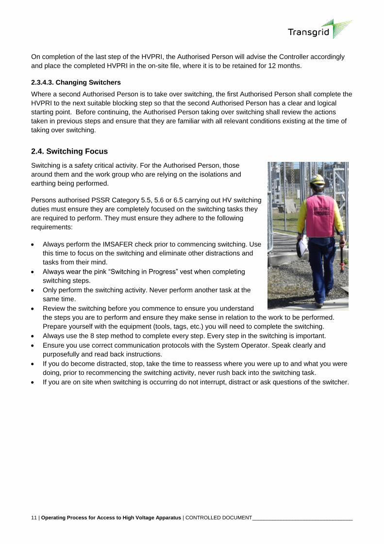
3. Generic Switching Process
NOTE: This process is a generic sequence, some sites and types of access have specific requirements.
Generic Switching Process
AP
IC
5.2
, 6.3
, 7
.3
Issu
er
5.4
, 6.4
, 7.5
Sw
itch
er
5.5
, 6.5
Co
ntr
olle
r
2.4
Obtain &
Check PRI
Notify
controller on
site
Update
Log
Write out Tags
& collect locks
Source
LVMPRI
(if required)
Lay out earths
(if required)
Update
Log
De-
Energising
Earthing
(if required)
Work
Update
Log
Remove
earthing
Update
Log &
give
clearance
Steps to
return to
service
Isolation(if required)
Update
Log & give
clearance
Receive
Clearance
Blocking
step?
Update
Log & give
clearance
Notify
controller
Receive
Clearance
Notify
controller
File
Do
cu
me
nta
tio
n
Yes
No
Notify
controller
On arrival at siteAA Issue &
CancelRestoration
Refer:
“Access for Work”
- Substation Apparatus
- Overhead Lines
- Transmission Cables; or
“Operating Process”
- Work on LV/MECH
Issue
AA No
Give
clearance
Carry out Preparation

13 | Operating Process for Access to High Voltage Apparatus | CONTROLLED DOCUMENT __________________________________________________________________________________________
3.1. On arrival to site
The switcher shall perform the steps listed below when arriving at site:
Step PSSR Authorisation
Task Comments Reference Document
1 5.5, 5.6, 6.5 Complete IMSAFER Self Check Consider whether you are affected by Illness, Medication, Stress, Alcohol, Fatigue, Emotion or Rushing. If you are you should not proceed until you are in a fit state or someone else who is in a fit state should be required to perform the switching task.
2 5.5, 6.5 Collect PRI from printer and ensure collation is correct Not required when using switching tablet This document section 2.3.3.2
3 5.5, 6.5 Check RFA matches PRI
4 5.5, 6.5 Check PRI against work requested Reference HVOD to confirm correct equipment, earthing etc.
5 5.5, 6.5 Switcher to notify Controller that they are onsite Or notify using switching tablet
6 5.5, 6.5 Write out required Tags (Do Not Operate or Warning Tags)
PRI number & date
7 5.5, 6.5 Collect required number of O1 locks Suitable locks may also be left at equipment
8 4.3, 5.5 If required, source LVMPRI for equipment to be worked on & write tags to suit required Isolations
Step performed if enough time prior to switching commencing
Access for Work on HV Substation Apparatus
9 5.5, 6.5 Lay out any required portable earths and connect to approved Earthing points at ground level
Step performed if enough time prior to switching commencing

14 | Operating Process for Access to High Voltage Apparatus | CONTROLLED DOCUMENT __________________________________________________________________________________________
3.2. Preparation
Step PSSR Authorisation
Task Comments Reference Document
1 5.5, 6.5 Receive Clearance from Controller to carry out PRI CB’s normally de-energised by Controller steps This document section 2.3.3.4
2 5.5, 6.5 Follow steps of PRI Carry out PRI to blocking step stated by Controller
Depending on the type of equipment, operating sequences will vary. The following sections describe generic sequences for different types of equipment.
3.2.1. De-energising or Offload - Operation of Circuit Breaker
Step Safety Rules Authorisation
Task Comments Reference Document
1 5.5, 6.5 Go to Control Panel of CB or CB symbol on HMI that matches name on PRI.
This document section 8.1
2 5.5, 6.5 Check associated current or power indication Panel meters, Power meter or HMI
3 5.5, 6.5 If required place auto re-close switch to ‘NON-AUTO’
4 5.5, 6.5 Open requested CB. Via Control Discrepancy Switch (CDS) or HMI
5 5.5, 6.5 After CB has been opened, check associated current or power indication is nil.
Panel meters, Power meter or HMI
6 5.5, 6.5 Cross out step in the PRI requesting the CB to be opened.
Use a non-obliterating line This document section 2.3.4.1
7 5.5, 6.5 Proceed to next step on PRI. If a blocking step, advise controller and receive clearance to proceed.

15 | Operating Process for Access to High Voltage Apparatus | CONTROLLED DOCUMENT __________________________________________________________________________________________
3.2.2. De-energising or Offload – Confirm Operation of Circuit Breaker
Step PSSR Authorisation
Task Comments Reference Document
1 5.5, 6.5 If required place auto re-close feature to ‘NON-AUTO’ This document section 8.1
2 5.5, 6.5 Proceed into Switchyard
3 5.5, 6.5 Check CB indicators are showing open.
4 5.5, 6.5 Cross out step in the PRI requesting the CB to be confirmed open.
Use a non-obliterating line This document section 2.3.4.1
5 5.5, 6.5 Proceed to next step on PRI. If a blocking step, advise Controller and receive clearance to proceed.
3.2.3. Isolation - Operation of Motorised Disconnector
Step PSSR Authorisation
Task Comments Reference Document
1 5.5, 6.5 Go to control panel of Disconnector or Disconnector symbol on HMI that matches name on PRI
Note: the HMI will often have an abbreviated name due to space. The full name and number may only be able to be read on the bay screen if at all unsure use other means to confirm correct switch prior to operating.
This document Section 8.3
2 5.5, 6.5 Check Disconnector name and number on control panel or HMI and check against PRI again.
3 5.5, 6.5 OPEN requested Disconnector via CDS switch or HMI. Problems that arise with the operation need to be referred to the Controller. Local operation may be permitted where remote operation is unserviceable
4 5.5, 6.5 Check indication on CDS or HMI Confirm disconnector indication is showing open.
5 5.5, 6.5 Cross out step in the PRI requesting the disconnector to be opened
Use a non-obliterating line
6 5.5, 6.5 Proceed into Switchyard to listed Disconnector

16 | Operating Process for Access to High Voltage Apparatus | CONTROLLED DOCUMENT __________________________________________________________________________________________
7 5.5, 6.5 Check all phases of disconnector are OPEN Visual checks shall be made to ensure that arms are fully open on all three phases
8 5.5, 6.5 Place Local / Remote Switch to “OFF” or “Local”
9 5.5, 6.5 Isolate motor supplies and apply tags per PRI step
Using one of the following methods:
Electrical interlock “OFF” as part of mechanical isolation
Removal of Fuses / Links; or
Switch “OFF” Thermal Over Load or Motor Supply MCB
Refer to the Standard Operating Instruction for the correct locking and tagging approach.
10 5.5, 6.5 Lock OPEN and apply tags specified by the PRI. Mechanically locked to prevent manual operation, where practicable
11 5.5, 6.5 Cross out step in the PRI requesting the disconnector to be checked open, locked and tags applied.
Use a non-obliterating line This document section 2.3.4.1
12 5.5, 6.5 Proceed to next step on PRI. If a blocking step, advise Controller and receive clearance to proceed.
3.2.4. Isolation - Operation of Manual Disconnector
Step PSSR Authorisation Task Comments Reference Document
1 5.5, 6.5 Proceed into Switchyard This document Section 8.3
2 5.5, 6.5 Check CB indicators are showing OPEN. On all poles - if provided and that the CB is in a satisfactory condition
3 5.5, 6.5 Proceed to listed Disconnector
4 5.5, 6.5 OPEN Disconnector The person carrying out the operation shall stand on the operator mat provided and not watch the contacts while the disconnector is operated

17 | Operating Process for Access to High Voltage Apparatus | CONTROLLED DOCUMENT __________________________________________________________________________________________
The manual opening or closing operation of a disconnector (or similar switch) shall be carried out in one complete and continuous movement,
5 5.5, 6.5 Check all phases of disconnector are OPEN Visual checks shall be made to ensure that arms are fully open on all three phases
6 5.5, 6.5 Lock OPEN and apply tags specified by the PRI
7 5.5, 6.5 Cross out step in the PRI requesting the disconnector to be checked open, locked and tags applied.
Use a non-obliterating line This document section 2.3.4.1
8 5.5, 6.5 Proceed to next step on PRI. If a blocking step, advise Controller and receive clearance to proceed.
3.2.5. Isolation – Voltage Transformer
Step PSSR Authorisation Task Comments Reference Document
1 5.5, 6.5 Identify correct VT Marshalling Box per PRI Switcher needs to ensure that where multiple secondary isolation boxes are present isolations are performed in both locations. This information is contained in the Switching Information Manual for the site and site signage also highlights this issue.
2 5.5, 6.5 Identify correct secondary isolation links Note, some Voltage transformers have multiple secondary windings and both windings need to be isolated.
3 5.5, 6.5 ISOLATE as required by PRI Appropriate tools and PPE for work on or near live LV exposed conductors. When SAD of 250mm from live exposed LV conductors not being operated cannot be maintained:
LV gloves shall be worn; or
Work shall be performed in accordance with an approved SWMS
Safe Work Practices on LV/MECH Apparatus

18 | Operating Process for Access to High Voltage Apparatus | CONTROLLED DOCUMENT __________________________________________________________________________________________
4 5.5, 6.5 Apply tags as requested by PRI
5 5.5, 6.5 Cross out step in the PRI requesting isolation of the voltage transformer secondary’s
6 5.5, 6.5 Proceed to next step on PRI. If a blocking step, advise Controller and receive clearance to proceed.
3.2.6. Isolation – 415V Transformer connections
For work on a power transformer, it is necessary to isolate from each point of supply typically requiring primary, secondary and tertiary isolations. In most
Transgrid transformer arrangements it is unusual to have isolation points in the 11kV circuit so typically these isolations are taken at the 415V switchgear.
How the 415V isolation is described on the HVOD will determine how the HVPRI step is written. Where a nominated isolation point is available, the naming of
that isolation point will be used. Where no isolation points are named a generic description will be used and the switcher will need to use an isolation point
suitable for the description of work and description of apparatus on the RFA.
Use of a 415V isolation device with a visible break is preferable as it provides a ready source for the work party to verify the isolation during the warnings and
demonstrations process. When the isolation is not provided by a device with a visible break, it must be by a device designed to provide isolation for the voltage
and the effectiveness of the isolation must be supported by a testing and earthing procedure. In this case the proving de-energised and the earthing applied after
isolation will be used as the testing and earthing procedure.
Isolation at the 415V is to be performed after the isolation of both the primary and secondaries. This will in general provide certainty that the circuit is de-
energised prior to operating the 415V isolating device. This is advantageous to safety as generally 415V isolations require the operator to be present locally at
the switchgear. Where remote operation points are available they should always be used in preference to local operation.
Isolation sequences to be followed for 415V isolations are similar to those described in sections 3.2.3 to 3.2.5.
19 | Operating Process for Access to High Voltage Apparatus | CONTROLLED DOCUMENT __________________________________________________________________________________________
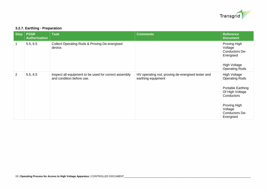
3.2.7. Earthing - Preparation
Step PSSR Authorisation
Task Comments Reference Document
1 5.5, 6.5 Collect Operating Rods & Proving De-energised device.
Proving High Voltage Conductors De-Energised
High Voltage Operating Rods
2 5.5, 6.5 Inspect all equipment to be used for correct assembly and condition before use.
HV operating rod, proving de-energised tester and earthing equipment
High Voltage Operating Rods
Portable Earthing Of High Voltage Conductors
Proving High Voltage Conductors De-Energised

20 | Operating Process for Access to High Voltage Apparatus | CONTROLLED DOCUMENT __________________________________________________________________________________________
The following sections describe the generic earthing sequence required for different types of apparatus.
3.2.8. Earthing - Earth Switch Manual
Step PSSR Authorisation
Task Comments Reference Document
1 5.5, 6.5 Proceed to earth switch identified on PRI.
2 5.5, 6.5 Set proving dead device to correct voltage and prove against a known supply of the same voltage that is being earthed.
Safe approach distances are to be maintained from all high voltage conductors whilst proving a high voltage conductor de-energised.
Proving High Voltage Conductors De-Energised
3 5.5, 6.5 Check conductors that are to be earthed are de-energised and re-test against a known supply of the same voltage that is being earthed.
Proving High Voltage Conductors De-Energised
4 5.5, 6.5 Place proving dead device back onto conductors that are to be earthed adjacent to phase nearest earth switch
Proving High Voltage Conductors De-Energised
5 5.5, 6.5 Unlock earth switch and CLOSE The person carrying out the operation shall stand on the operator mat provided and not watch the contacts while the disconnector is operated. The manual opening or closing operation of an earth switch shall be carried out in one complete and continuous movement
6 5.5, 6.5 Check that all phases are closed correctly Visual checks shall be made to ensure that contacts are secured by contact pressure or drive tension and arms are fully home on all three phases
7 5.5, 6.5 Lock CLOSED (if required) and apply tags specified by the PRI
If earths form part of testing, locking is not required and a “Warning” tag to be applied.
8 5.5, 6.5 Cross out step in the PRI requesting the earth switch to be closed.
Use a non-obliterating line This document section 2.3.4.1

21 | Operating Process for Access to High Voltage Apparatus | CONTROLLED DOCUMENT __________________________________________________________________________________________
9 5.5, 6.5 Proceed to next step on PRI. If a blocking step, advise Controller and receive clearance to proceed.
3.2.9. Earthing - Earth Switch Motorised
Step PSSR Authorisation Task Comments Reference Document
1 5.5, 6.5 Proceed to earth switch identified on PRI.
2 5.5, 6.5 Set proving dead device to correct voltage and prove against a known supply of the same voltage that is being earthed.
Maintain safe approach distance from all high voltage conductors
Proving High Voltage Conductors De-Energised
3 5.5, 6.5 Check conductors that are to be earthed are de-energised and re-test against a known supply of the same voltage that is being earthed.
Proving High Voltage Conductors De-Energised
4 5.5, 6.5 Place proving dead device back onto conductors that are to be earthed adjacent to phase nearest earth switch
Proving High Voltage Conductors De-Energised
5 5.5, 6.5 Unlock earth switch and CLOSE The person carrying out the operation shall stand on the operator mat provided and not watch the contacts while the disconnector is operated
6 5.5, 6.5 Check that all phases are closed correctly Visual checks shall be made to ensure that contacts are secured by contact pressure or drive tension and arms are fully home on all three phases
7 5.5, 6.5 Place Local Remote Switch to “OFF” or “Local”
8 5.5, 6.5 Isolate motor supplies and apply tags per PRI step
Using one of the following methods:
Electrical interlock “OFF” as part of mechanical isolation
22 | Operating Process for Access to High Voltage Apparatus | CONTROLLED DOCUMENT __________________________________________________________________________________________
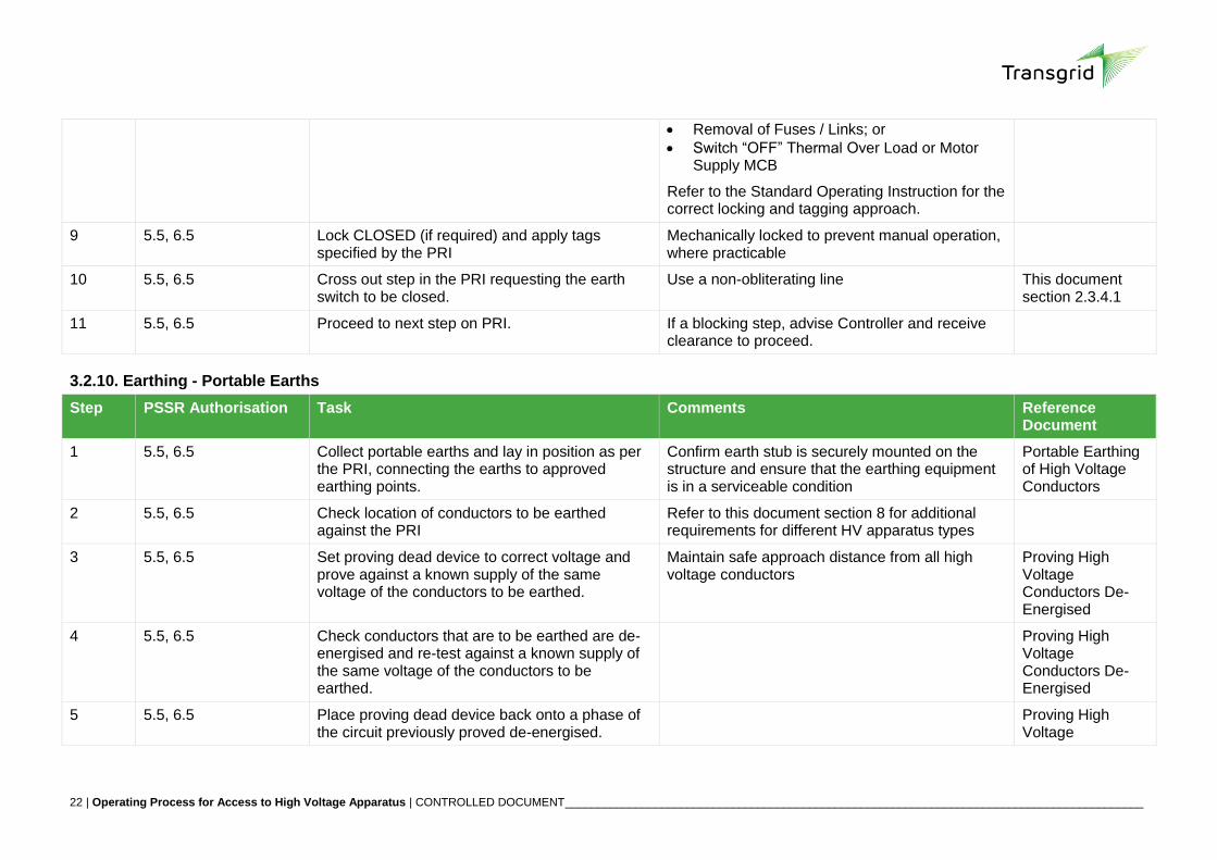
Removal of Fuses / Links; or
Switch “OFF” Thermal Over Load or Motor Supply MCB
Refer to the Standard Operating Instruction for the correct locking and tagging approach.
9 5.5, 6.5 Lock CLOSED (if required) and apply tags specified by the PRI
Mechanically locked to prevent manual operation, where practicable
10 5.5, 6.5 Cross out step in the PRI requesting the earth switch to be closed.
Use a non-obliterating line This document section 2.3.4.1
11 5.5, 6.5 Proceed to next step on PRI. If a blocking step, advise Controller and receive clearance to proceed.
3.2.10. Earthing - Portable Earths
Step PSSR Authorisation Task Comments Reference Document
1 5.5, 6.5 Collect portable earths and lay in position as per the PRI, connecting the earths to approved earthing points.
Confirm earth stub is securely mounted on the structure and ensure that the earthing equipment is in a serviceable condition
Portable Earthing of High Voltage Conductors
2 5.5, 6.5 Check location of conductors to be earthed against the PRI
Refer to this document section 8 for additional requirements for different HV apparatus types
3 5.5, 6.5 Set proving dead device to correct voltage and prove against a known supply of the same voltage of the conductors to be earthed.
Maintain safe approach distance from all high voltage conductors
Proving High Voltage Conductors De-Energised
4 5.5, 6.5 Check conductors that are to be earthed are de-energised and re-test against a known supply of the same voltage of the conductors to be earthed.
Proving High Voltage Conductors De-Energised
5 5.5, 6.5 Place proving dead device back onto a phase of the circuit previously proved de-energised.
Proving High Voltage

23 | Operating Process for Access to High Voltage Apparatus | CONTROLLED DOCUMENT __________________________________________________________________________________________
Conductors De-Energised
6 5.5, 6.5 Apply the earth clamp on phase to be earthed.
7 5.5, 6.5 Repeat Steps (5) & (6) above for each phase to be earthed. Apply tags specified by the PRI to each earth lead.
8 5.5, 6.5 Remove tester from conductor
9 5.5, 6.5 Cross out step in the PRI requesting the earths to be applied
Use a non-obliterating line This document section 2.3.4.1
10 5.5, 6.5 Proceed to next step on PRI. If a blocking step, advise Controller and receive clearance to proceed.
3.2.11. Earthing for inadvertent re-energisation from the tertiary connections.
As described in 3.2.6 for work on transformers, isolation is typically required on the 415V connections to prevent back energisation of the transformer from the
tertiary winding side. In case of inadvertent restoration of that isolation earths must be applied between the work party and the point of isolation on the 415V
side.
HVPRI procedures preference the application of earths for this situation on the 11kV conductors wherever possible. There are two circumstances where the
application of the earths at 11kV is not possible:
1. Where there is no ability to access the 11kV conductors
2. Where the work requires breaking connections at the 11kV terminals of the auxiliary transformer making an earth applied at 11kV ineffective if the 415V
isolation was inadvertently restored.
In these situations earths will be required on the 415V terminals. Earthing at the 415V terminals must be suitable for the rating in the event of inadvertent re-
energisation. Requirements for earthing of this type are described in the procedure “Portable earthing of High Voltage Conductors”.
This earthing shall only be applied after proving de-energised in accordance with the procedure “Proving HV Conductors de-energised”.
3.2.12. Earthing – Voltage Transformer Secondaries
Step PSSR Authorisation Task Comments Reference

24 | Operating Process for Access to High Voltage Apparatus | CONTROLLED DOCUMENT __________________________________________________________________________________________
Document
1 5.5, 6.5 Identify correct VT Marshaling Box per PRI
2 5.5, 6.5 Identify correct secondary isolation links
3 5.5, 6.5 Prove de-energised at secondary isolation links Using approved two-pole voltage & continuity tester
Proving High Voltage Conductors De-Energised
4 5.5, 6.5 Earth as required by PRI When SAD of 250mm from live exposed LV conductors not being operated cannot be maintained:
LV gloves shall be worn; or
Work shall be performed in accordance with an approved SWMS
Safe Work Practices on LV/MECH Apparatus
5 5.5, 6.5 Apply tags as required by PRI
6 5.5, 6.5 Cross out step in the PRI requesting earthing of voltage transformer secondaries.
Use a non-obliterating line. If a blocking step, advise Controller and receive clearance to proceed.
This document section 2.3.4.1
25 | Operating Process for Access to High Voltage Apparatus | CONTROLLED DOCUMENT __________________________________________________________________________________________
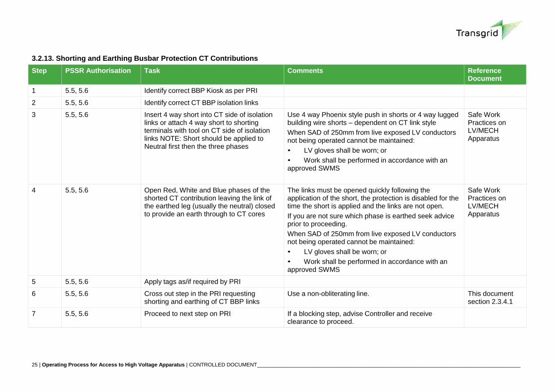
3.2.13. Shorting and Earthing Busbar Protection CT Contributions
Step PSSR Authorisation Task Comments Reference Document
1 5.5, 5.6 Identify correct BBP Kiosk as per PRI
2 5.5, 5.6 Identify correct CT BBP isolation links
3 5.5, 5.6 Insert 4 way short into CT side of isolation links or attach 4 way short to shorting terminals with tool on CT side of isolation links NOTE: Short should be applied to Neutral first then the three phases
Use 4 way Phoenix style push in shorts or 4 way lugged building wire shorts – dependent on CT link style
When SAD of 250mm from live exposed LV conductors not being operated cannot be maintained:
• LV gloves shall be worn; or
• Work shall be performed in accordance with an approved SWMS
Safe Work Practices on LV/MECH Apparatus
4 5.5, 5.6 Open Red, White and Blue phases of the shorted CT contribution leaving the link of the earthed leg (usually the neutral) closed to provide an earth through to CT cores
The links must be opened quickly following the application of the short, the protection is disabled for the time the short is applied and the links are not open.
If you are not sure which phase is earthed seek advice prior to proceeding.
When SAD of 250mm from live exposed LV conductors not being operated cannot be maintained:
• LV gloves shall be worn; or
• Work shall be performed in accordance with an approved SWMS
Safe Work Practices on LV/MECH Apparatus
5 5.5, 5.6 Apply tags as/if required by PRI
6 5.5, 5.6 Cross out step in the PRI requesting shorting and earthing of CT BBP links
Use a non-obliterating line. This document section 2.3.4.1
7 5.5, 5.6 Proceed to next step on PRI If a blocking step, advise Controller and receive clearance to proceed.

26 | Operating Process for Access to High Voltage Apparatus | CONTROLLED DOCUMENT __________________________________________________________________________________________
3.3. Access Authority Issue and Cancellation
Apparatus PSSR Authorisation Task Comments Reference Document
Substation HV Apparatus
5.4 Issue HV Access Authority
Cancel HV Access Authority
Access for Work on High Voltage Substation Apparatus
Access for Work on High Voltage Substation Apparatus
Overhead Lines 6.4 Issue Field Access Authority
Cancel Field Access Authority
Access for Work on High Voltage Overhead Lines
Access for Work on High Voltage Overhead Lines
Transmission Cables 7.5 Issue Cable Access Authority
Cancel Cable Access Authority
Access for Work on High Voltage Transmission Cables
Access for Work on High Voltage Transmission Cables
3.4. Restoration
Step PSSR Authorisation Task Comments Reference Document
1 5.5, 5.6, 6.5 Complete IMSAFER Self Check Consider whether you are affected by Illness, Medication, Stress, Alcohol, Fatigue, Emotion or Rushing. If you are you should not proceed until you are in a fit state or someone else who is in a fit state should be required to perform the switching task.
2 5.5, 6.5 Receive clearance from Controller to carry out PRI
Carry out PRI to blocking step stated by Controller This document section 2.3.3.4
3 5.5, 6.5 Follow steps of PRI Cross out steps as completed with a non-obliterating line

27 | Operating Process for Access to High Voltage Apparatus | CONTROLLED DOCUMENT __________________________________________________________________________________________
3.4.1. Removal of Earthing - Earth Switch
Step PSSR Authorisation Task Comments Reference Document
1 5.5, 6.5 Identify correct earth switch per PRI
2 5.5, 6.5 Remove Tags, unlock and OPEN earth switch. If motorised earth switch:
Restore motor supplies; and
Place local / remote switch to local
3 5.5, 6.5 Check that all three (3) phases have opened correctly
Visual checks shall be made to ensure that arms are fully open on all three phases
4 5.5, 6.5 Lock OPEN the earth switch If motorised earth switch:
Place local / remote switch to OFF
5 5.5, 6.5 Cross out step in the PRI requesting the earth switch opened.
Use non – obliterating line
6 5.5, 6.5 Proceed to next step on PRI. If a blocking step, advise Controller and receive clearance to proceed.
3.4.2. Removal of Earthing - Portable Earths
Step PSSR Authorisation Task Comments Reference Document
1 5.5, 6.5 Check correct location of portable earths to be removed per the PRI
2 5.5, 6.5 Remove tags
3 5.5, 6.5 Remove earths Return to correct storage location at completion of PRI
Portable Earthing of High Voltage Conductors
4 5.5, 6.5 Cross out step in the PRI requesting the earths to be removed
ONLY after all three phases are removed
5 5.5, 6.5 Proceed to next step on PRI If a blocking step, advise Controller and receive

28 | Operating Process for Access to High Voltage Apparatus | CONTROLLED DOCUMENT __________________________________________________________________________________________
clearance to proceed.
3.4.3. Removal of Earthing – VT Secondaries
Step PSSR Authorisation Task Comments Reference Document
1 5.5, 6.5 Identify correct VT Marshalling Box per PRI
2 5.5, 6.5 Identify correct secondary isolation links
3 5.5, 6.5 Remove Tags
4 5.5, 6.5 Remove earth(s) Appropriate tools and PPE for work on or near live LV exposed conductors. When SAD of 250mm from live exposed LV conductors not being operated cannot be maintained:
LV gloves shall be worn; or
Work shall be performed in accordance with an approved SWMS
Safe Work Practices on LV/MECH Apparatus
5 5.5, 6.5 Cross out step in the PRI requesting removal of earthing from the voltage transformer secondaries.
Use a non-obliterating line This document section 2.3.4.1
6 5.5, 6.5 Proceed to next step on PRI. If a blocking step, advise Controller and receive clearance to proceed.
3.4.4. Removal of Earthing and Shorting of BBP CT contributions
Step PSSR Authorisation Task Comments Reference Document
1 5.5, 5.6 Identify correct BBP Kiosk as per PRI
2 5.5, 5.6 Identify correct CT BBP isolation links
3 5.5, 5.6 Remove tags (if PRI required them)
4 5.5, 5.6 Close Red White and Blue phase links, confirm When SAD of 250mm from live exposed LV conductors not being operated cannot be
Safe Work Practices on

29 | Operating Process for Access to High Voltage Apparatus | CONTROLLED DOCUMENT __________________________________________________________________________________________
Neutral link is still closed maintained:
• LV gloves shall be worn; or
• Work shall be performed in accordance with an approved SWMS
LV/MECH Apparatus
5 5.5, 5.6 Remove 4 way short from CT contribution links When SAD of 250mm from live exposed LV conductors not being operated cannot be maintained:
• LV gloves shall be worn; or
• Work shall be performed in accordance with an approved SWMS
Safe Work Practices on LV/MECH Apparatus
6 5.5, 5.6 Cross out step in the PRI requesting removal of earthing and short from the BBP CT Contributions.
Use a non-obliterating line This document section 2.3.4.1
7 5.5, 5.6 Proceed to next step on PRI. If a blocking step, advise Controller and receive clearance to proceed.
3.4.5. Return to Service
Step PSSR Authorisation Task Comments Reference Document
1 5.5, 6.5 Receive clearance from Controller to carry out PRI Carry out PRI to blocking step stated by Controller
2 5.5, 6.5 Check associated CB is OPEN
3 5.5, 6.5 Identify correct VT Marshalling Box per PRI
4 5.5, 6.5 Identify correct secondary isolation links
5 5.5, 6.5 RESTORE as required by PRI Appropriate tools and PPE for work on or near live LV exposed conductors. When SAD of 250mm from live exposed LV conductors not being operated cannot be maintained:
LV gloves shall be worn; or
Safe Work Practices on LV/MECH Apparatus

30 | Operating Process for Access to High Voltage Apparatus | CONTROLLED DOCUMENT __________________________________________________________________________________________
Work shall be performed in accordance with an approved SWMS
6 5.5, 6.5 Cross out step in the PRI requesting restoration of the VT secondaries
7 5.5, 6.5 Proceed to next step on PRI.
8 5.5, 6.5 Proceed to the listed disconnector
9 5.5, 6.5 Remove Tags
10 5.5, 6.5 Unlock disconnector If motorised disconnector:
Restore motor supplies; and
Place local / remote switch to REMOTE
11 5.5, 6.5 CLOSE Disconnector/s as per the PRI If motorised disconnector CLOSE requested Disconnector remotely
12 5.5, 6.5 At the apparatus visually confirm Disconnector/s CLOSED
Visual checks shall be made to ensure that contacts are secured by contact pressure or drive tension and arms are fully home on all three phases
If manual disconnector, the disconnector shall then be secured against movement caused by wind, vibration or magnetic forces etc., by inserting the holding bolt in the operating handle
13 5.5, 6.5 Cross out step in the PRI requesting the disconnector to be closed
14 5.5, 6.5 Proceed to next step on PRI.
15 5.5, 6.5 If required by PRI place auto re-close switch on ‘AUTO’
16 5.5, 6.5 Advise Controller when blocking step has been reached and that equipment is ready for service
CB’s normally energised by Controller steps

31 | Operating Process for Access to High Voltage Apparatus | CONTROLLED DOCUMENT __________________________________________________________________________________________
17 5.5, 6.5 File ‘used PRI’ and associated documentation In designated filing cabinet.

32 | Operating Process for Access to High Voltage Apparatus | CONTROLLED DOCUMENT ___________________________________
4. Operating Gas Insulated Switchgear (GIS)
4.1. Power System Safety Rules Requirements
The Power System Safety Rules require that:
Making GIS Safe for Work
For normal switching operations, GIS shall be operated remotely using the substation Human machine
Interface (HMI) or other remote control facility; and
Manual operation of GIS for switching purposes shall not be considered when equipment is energised,
as this will bypass all interlocking.
Normally GIS switchgear must be operated remotely. Operation from the local control cubicle is not
considered to be remote operation therefore if remote operation is not possible then addition precautions
are required as detailed in Section 4.4.
In addition to these requirements, all workers shall vacate the GIS hall during switching operations.
4.2. General Requirements
4.2.1. Electrical and Mechanical Safety features
Extensive interlocking is provided at GIS substations and on GIS switchgear to inhibit the closing of an
earth onto live High Voltage conductors. Safety may also be provided by three-position switches that are
mechanically designed to prevent any individual phase from being in more than one state at any one time,
i.e. a phase that switches to earth cannot physically also be in the closed position at the same time.
Characteristics of equipment specific to individual sites are provided in the Switching Information Manuals
and Standard Operating Instructions for GIS Sites.
4.2.2. Defeating of Interlocks during Operational Switching
Where the nature of the work requires the defeating of interlocks during operational switching Rules 5.6.8
and 5.6.9 of the Power System Safety Rules apply.
4.2.3. Defeating of Interlocks during work under an Access Authority
Following the issue of an Access Authority, defeat of interlocking on equipment under the work party’s
control as part of the Access Authority is permitted. Defeating of interlocking shall be performed by a
person familiar with the operation of the equipment and the interlocks. In normal circumstances this would
be a person authorised category 5.6. Interlocks defeated during the currency of the Access Authority must
be restored prior to the cancellation of the Access Authority.
4.2.4. Preparation of Switching Instructions
The High Voltage Preparation and Restoration Instruction will not be written in a manner that prescribes
remote or local operation for each step. This will assist the work where remote operation is unexpectedly
unavailable. It will be the responsibility of the authorised person performing the switching to comply with the
requirements of section 4.3 and 4.4 of this procedure.
Example GIS switching sequences that are written in this style are provided in Appendix C.

33 | Operating Process for Access to High Voltage Apparatus | CONTROLLED DOCUMENT ___________________________________
4.2.5. Order of Switching Operations
All switching shall be carried out in accordance with all the normal rules and conventions except:
Earths may be applied prior to isolating VT secondary circuits and will be the normal practice;
Visual checking of individual switchgear status using the mechanical indication is not required.
Locking and tagging of apparatus shall be undertaken when convenient, rather than immediately after
completing each individual operation. This is to allow the switcher to complete a number of remote
operations before returning to the switchgear.
Note: For certain types of switchgear it is necessary to lock the isolators before closing the earths.
4.3. Making GIS Equipment Safe for Work using Remote Operation
Where Remote operation of GIS switchgear is available the requirements of this section apply.
An example GIS switching sequence that complies with this procedure is provided in Appendix C.
4.3.1. Isolation
Isolation will be in accordance with Rule 5.6.2(a) of the Safety Rules. The switchgear position on the HMI
satisfies the requirements of this rule.
4.3.2. Earthing
The application of HV Access Authority earths shall be in accordance with Rule 5.6.3 of the Power System
Safety Rules. An approved earthing method shall be used that ensures:
Earthing switches shall only be closed onto High Voltage conductors that are identified as de-energised
from all sources by voltage and/or disconnector indication.
Earthing switches may be applied to High Voltage conductors that are identified as de-energised if the
earth is already in place and is being extended to other conductors by the closure of a circuit breaker.
4.3.3. Securing the Isolation and Earthing
This is to be done on the switchgear level by locking / tagging effective points of isolation in their open
positions and locking / tagging effective earthing switches in their closed positions
4.4. Making GIS Equipment Safe to Work where Local operation is required
When there is no capability to operate the GIS equipment remotely or the remote capability is not
functioning then Rule 5.6.6 of the Power System Safety Rules applies. The additional safety precautions
applicable in such circumstances are as follows:
4.4.1. Isolation
The indication of the switchgear position must be established visually, either directly or by using
appropriate cameras. The gas pressure must also be confirmed as satisfactory.
4.4.2. Earthing
There are no additional requirements when earthing locally.

34 | Operating Process for Access to High Voltage Apparatus | CONTROLLED DOCUMENT ___________________________________
5. Site log and incidents
5.1. Operating functions that are not steps in a PRI
Operating functions that are not steps in a PRI shall be fully recorded in the site log. Examples of relevant
functions are:
Operational switching of circuit breakers without the use of a PRI;
Switching of HV equipment during an emergency without the use of a PRI – Commonly referred to as
Log Entry Switching;
Local operation of an Auto Reclose/ Auto Close/ Time Switch Control that is not a step in a PRI;
Messages to and from the Controller relating to significant occurrences, unusual conditions and
observations at the station (including circuit breaker operations not included in a HVPRI); and
Any other matter affecting the safe and efficient operation of the substation.
Note: Such functions must be communicated to the Controller and must only be carried out by an
appropriately Authorised Person.
5.2. Recording of Site Incidents
When responding to a system incident e.g. equipment trip, then a Site Incident Record Sheet shall be
completed, this includes sections for all protection details etc. Once completed, this form is to be
forwarded to the Controller; there is no need to duplicate this information in the switching log book.
6. Tags and Labels
Tags and labels are used to indicate temporary abnormal conditions of apparatus. Printed tags and labels
are physically attached to equipment whereas electronic tags associated with supervisory systems
(SCADA and HMI etc.) are graphic symbols shown adjacent to a device on the display. The following tags
and labels are in use:
Do Not Operate Tag (DNOT)
Warning Tag (WT)
Unusual Condition Label (UCL)
Control Inhibited Tag (CIT)
6.1. Do Not Operate Tags and Warning Tags
Use of DNOTs and WTs is controlled because they are part of the process to set up safe working
conditions on or near high voltage, low voltage and mechanical apparatus in the charge of the Controller.
Application and removal of DNOTs and WTs in this circumstance shall only be carried out by a person
authorised PSSR Category 4.3, 5.5, 5.6 or 6.5.
Do Not Operate Tag - PROHIBITS personnel from operating any device switch, control, valve, link
etc., to which it is attached.
Warning Tag allows LIMITED OPERATION of the device or control to which it is attached, to the extent
indicated on the tag.

35 | Operating Process for Access to High Voltage Apparatus | CONTROLLED DOCUMENT ___________________________________
6.1.1. Obsolete Do Not Operate Tags or Warning Tags
If a DNOT or WT is found attached to apparatus which is required to be operated, and it is likely that the
tag is obsolete the matter shall be investigated by the Controller, who shall establish from records of
Access Authorities whether the tag is no longer applicable and can be removed.
6.2. Control Inhibit Tags
Where supervisory control is provided, an electronic Control Inhibit Tag (CIT) shall be used in lieu of a
paper tag as part of the safe working conditions established when work is required on or near HV
apparatus or for security of the system. A CIT shall be used primarily for visual indication and not for work
party safety for which isolations which can be proven are to be used.
7. Locking Of High Voltage Switchgear
O1 Series – ‘Operator’ key locks are provided for locking of switchgear and other operating purposes and
the associated keys are only issued to person’s authorised PSSR Category 5.5, 5.6 and 6.5.
When locking HV switchgear the following points are to be observed:
(a) HV switches required open for isolation purposes must be locked open unless an approved alternative
procedure is available;
(b) Locks should not be applied to HV switches in substations that are open or closed for system operating
requirement only;
(c) No in-service HV disconnector in a substation is to be locked closed, unless:
- Environmental factors could cause maloperation; or
- When directed by the Controller;
(d) Earthing switches must be locked in either the open or closed position except when provision is made
for a switch to be operated in association with a Testing Access Authority, or when an approved
alternative procedure that does not require locking exists for the specific equipment;
(e) Where a HVPRI requires HV switches to be locked, where practicable, the disconnector or earthing
switch shall be mechanically locked to prevent manual operation;
(f) When special individual locks are provided for each switch (e.g. on SF6 switchgear), corresponding
individual keys will normally be kept in a dedicated key cabinet located in the control room; and
(g) Where a motor operated disconnector or earthing switches can be operated from local or remote
control points, each device shall be isolated from its operating supply source and tags as per the
HVPRI shall be attached at the point of isolation. This requirement is normally not included as a
detailed step in the HVPRI and it is the responsibility of the person carrying out the HVPRI to ensure
familiarity with different apparatus types. Standard Operating Instructions are available to guide
authorised persons on the correct way to isolate and tag motorised disconnectors and earthing
switches.
36 | Operating Process for Access to High Voltage Apparatus | CONTROLLED DOCUMENT ___________________________________
8. General Operating Principles
8.1. Circuit Breakers
Whenever possible, load break switching operations shall be carried out using circuit breakers or load-
breaking circuit switches. Some circuit breakers have multiple interrupter units per pole, in which case they
are usually provided with grading capacitors to ensure uniform voltage distribution. Also, some types of
circuit breakers are fitted with breaking resistors that are connected in parallel with the main contacts for
dampening transient recovery voltages. Circuit breakers, in general, may be operated according to system
requirements without risk of failure, but nameplate ratings and specific local limitations must be observed.
8.1.1. Operating requirements for circuit breakers
HV circuit breakers may only be operated as a step in a PRI or with the specific approval of the
Controller, except in an emergency. Operations for maintenance checks, testing and commissioning
may also take place in accordance with procedures relevant to the work.
Where a circuit breaker is considered to be defective it should be de-energised by the operation of
another circuit breaker to reduce the risk of damage to equipment, danger to personnel and effects on
system security.
Should there be any apparent abnormality within the substation or other reason that suggests that the
CB should not be operated, refer to the Controller for advice before proceeding.
In the case of automatically switched capacitors or reactors (e.g. those controlled by time switches,
voltage level etc.) Select control to non-auto before operating the CB.
Check what instruments are available on the control panel as operating aids, consider their expected
behaviour and check that the behaviour occurs during operation.
Circuit breakers shall preferably be operated remotely, from the Network Operations’ control room.
Otherwise the circuit breaker shall be operated from the CB control panel in the substation control
room/relay room, as follows:
Opening a circuit breaker
(a) Check whether the circuit is carrying load. If so, check that an alternative parallel supply is available to
pick up that load. If this can’t be checked locally, receive assurance from the Controller that an
alternative supply is available. This principle applies to auxiliary supplies as well as external load. If
the ammeter reading is near zero, press the fine scale button (where provided) and watch for pointer
movement.
(b) In the case of generating units, gradually reduce the load to zero before switching to avoid frequency or
voltage surges, damage to plant and to reduce the breaking duty of the CB.
(c) First select the CB to be opened, and then check that the correct CB has been selected before
proceeding to open the CB.
(d) Immediately after opening the CB, check the ammeters to ensure that the expected load drop off or
pick-up has occurred on alternative circuits and that no overload has arisen. Check that voltage
conditions are satisfactory and that auxiliary supplies are still effective.
(e) Check that the local (at the circuit breaker) indicator on the CB shows 'open' (on all poles - if provided)
and that the CB is in a satisfactory condition.
(f) For those CBs where the close operation is performed mechanically by a spring, check that the spring
has recharged.

37 | Operating Process for Access to High Voltage Apparatus | CONTROLLED DOCUMENT ___________________________________
Closing a circuit breaker
(a) Check local conditions: The CB control switch, in the local cabinet, must be selected to remote.
LV/mechanical isolations must have been restored. All associated protection devices must be auto and
there should be no relays showing an operation. Any abnormality (relays operated or flags down)
should be reported to the Controller and then be reset when requested. There should be no alarms
associated with the CB.
(b) If required by the HVPRI, check that the line auto-reclose facility, if provided, is in the non-auto
condition. Auto reclose is not normally made non-auto where there is duplicate memory protection
installed.
(c) If required by the HVPRI, synchronising facilities must be used to check synchronism and matching
phase angle and voltage levels across the CB before closing it. Synchronising is normally auto except
in power stations.
(d) Select the CB to be closed, and then check that the correct CB has been selected before proceeding to
close the CB.
(e) During the close operation, observe the behaviour of ammeter, voltmeter and control room lighting.
Should the circuit breaker trip on an attempted closure, these indications are valuable aids in
diagnosing whether there has been a HV fault, or some malfunction of protection, or non-latching of the
CB.
(f) After the CB has been closed ensure, unless instructed otherwise by the Controller, that:
(g) CB control is restored to the normal remote/supervisory condition;
(h) Auto reclose is normally made auto and Auto closing is normally non-auto, any discrepancies are to be
referred to the Controller;
(i) Automatic control of capacitors or reactors (e.g. by time switch, voltage etc.) is normally made auto, any
discrepancies are to be referred to the Controller;
(j) Check that the local CB indicator is showing 'closed' (on all poles - if provided) and that the CB is in a
satisfactory condition;
(k) For those CBs where the close operation is performed mechanically by a spring, check that the spring
has been recharged after closing of the CB and all alarms associated with the CB are reset.
8.1.2. General limitations - Circuit breakers
8.1.2.1. Current rating
Loadings must not exceed the published ratings except when a higher loading is approved for special
purposes. Circuit ratings are set out in 300 series OMs, which take into account the current carrying
capacity of the circuit breaker.
Rupturing duty
Generally, circuit breaker operation above rated rupturing capacity is not permitted. However, in specific
cases the rated rupturing capacity may be temporarily exceeded with the approval of the Manager/Network
Operations. An example would be that if the only alternative would be interruption to supply, then under
abnormal conditions normal rupturing capability might be exceeded for the short period during supply re-
arrangement.

38 | Operating Process for Access to High Voltage Apparatus | CONTROLLED DOCUMENT ___________________________________
Circuit breaker maximum duty cycles
Circuit breakers may have a limit to the number of operations within a given time, as follows:
Circuit breakers with breaking resistors
Some circuit breakers (particularly 500kV and some lower voltage small oil volume circuit breakers) are
fitted with breaking resistors to dampen transient recovery voltages (TRV). These resistors are connected
in parallel with the main interrupters and following the opening of the main contacts auxiliary interrupters
open the breaking resistor circuits. Tripping operations cause heating of the resistors and to avoid the risk
of damage due to thermal build-up, the number of successive trips must be limited. In general, circuit
breaker specifications allow for an operating sequence of TRIP - CLOSE - TRIP -
3 MINUTE TIME DELAY - CLOSE – TRIP. A trip followed by auto-reclose and trip must be counted as
two trip operations.
In addition, limitations apply to certain makes of circuit breakers with respect to breaking: load current, fault
current, line (or cable) charging current and capacitor charging current. No limitation applies to the
frequency of switching transformer magnetising current.
Circuit breakers without breaking resistors
SF6 and pressurised head, small oil volume circuit breakers do not require breaking resistors. Although
these circuit breakers have no resistor thermal limitations, the general TRIP - CLOSE - TRIP -
3 MINUTE TIME DELAY - CLOSE - TRIP operating sequence still applies.
Other operating limitations
Hydraulically operated CBs must not be operated if the hydraulic pressure is below the limits prescribed
for the particular CB.
In the case of SF6 gas interrupters there is a possibility of the SF6 gas leaking from the interrupter units
at a rate of approximately 1% per year, relative to gas quantity. As the gas acts as a damper, these circuit
breakers must not be operated if the poles do not contain SF6 gas.
Double Pressure CBs: The operation of double pressure SF6 CBs depends on the SF6 pressure
differential between the high and low pressure gas chambers and they must not be operated if this
differential pressure drops below the limits prescribed for the CB.
Single Pressure CBs: Single pressure SF6 CBs must generally have a nominal pressure in the
interrupter, below which it is recommended that the CB not be operated. Gas pressure monitoring (gas
density relay) will initiate an alarm if the SF6 gas pressure drops to a point where lockout is imminent.
Lockout circuitry is provided to prevent the CB from being operated if the SF6 pressure is too low for
safe operation.
8.2. High Voltage Capacitors and Reactors
8.2.1. High Voltage Power Capacitors
Shunt connected HV power capacitors are used for voltage control. Most such capacitors comprise banks
of multiple cans mounted on racks and connected in double star. The mounting racks are generally not
connected to earth. Star point earthing depends on the bank arrangement.

39 | Operating Process for Access to High Voltage Apparatus | CONTROLLED DOCUMENT ___________________________________
Capacitor circuit breaker operation
A circuit breaker shall be used at all times to switch high voltage power capacitors into or out of service. To
minimise surges and/or damage when switching the capacitors the designated capacitor circuit breaker
should be used, as it will have been designed for capacitor switching duty, with point on wave facility when
appropriate.
Capacitor residual charge
HV DC charge might be left on a capacitor and its framework after removing supply. Because of this, a
period of at least ten minutes should elapse between the time a HV capacitor is switched out of service and
the start of further operations, which will allow the residual charge to dissipate. Specifically, a capacitor is
not to be re-energised until at least ten minutes after being de-energised. This will avoid voltage-doubling
effects from switching onto residual HV DC charge, which could cause protection fuses to rupture and
possibly damage the capacitor.
8.2.2. HV Capacitor Earthing
The capacitor bank should be earthed by operation of an earthing switch on the primary supply conductors
where an earthing switch is provided. Capacitor banks have internal discharge circuits to dissipate any
residual charge after they are de-energised. Reduction of the capacitor voltage to a safe level for earthing
requires time for the discharge circuit to operate. As proving de-energised equipment will not indicate the
presence of any residual HV DC charge, earthing is not to commence for at least the time specified on the
Capacitor bank nameplate, where this information is not available the switcher is to wait ten minutes after
de-energising to allow the residual charge to dissipate and ensure safe conditions for earthing. After having
been proven de-energised the star points of the capacitor as well as the supply conductors on each phase
must be earthed to effectively short and earth each phase of the capacitor bank. Where the capacitor bank
comprises two parallel sections, each with its own star point, the authorised person shall visibly check the
connection between the star points for continuity before applying earthing and apply the same procedure to
each section if the star points are not connected.
8.2.3. High Voltage Power Reactors
Shunt connected HV power reactors are also used for voltage control. Although not subject to the same
residual charge problems as capacitors, a circuit breaker shall be used at all times to switch high voltage
power reactors into or out of service to minimise surges and/or damage.
8.2.4. Operating requirements for control schemes
All control devices shall be selected to the non-auto position before any circuit breaker operation to avoid
hunting effects should the control scheme initiate an operation during a manual switching sequence.
Any auto-switching scheme shall be selected to the non-auto position before resetting capacitor or reactor
protection MTM relays after fault tripping. This is to prevent an uncontrolled operation of the capacitor or
reactor circuit breaker when the protection MTM relays are reset. When the protection MTM relay
operates, contacts in the automatic control circuit are broken in order to prevent the scheme reclosing the
circuit breaker onto faulted equipment and when the MTM is reset the automatic control circuit is remade
and conditions on the network could cause operation of the auto-switching scheme.
Automatic Control of Capacitors And Reactors

40 | Operating Process for Access to High Voltage Apparatus | CONTROLLED DOCUMENT ___________________________________
HV shunt power capacitors and reactors often have automatic controls that will switch the units in and out
of service to assist with system voltage control (refer to Operating Manuals). Where there are automatic
controls, the circuit breaker discrepancy (CDS) switch on the control panel will commonly be left with the
knob pointing to the “OPEN” status position to prevent a ‘Circuit Breaker Tripped’ alarm being activated
every time the automatic control initiates an ‘Open’ command. Such operation causes the lamp to be on
over an extended period to indicate a discrepancy and they can burn out. Lamp integrity on these devices
should be checked to ensure the indication is reliable and there is no confusion between a blown lamp and
a dark lamp condition.
Time switch control
Used on smaller installations where remote supervisory control equipment is not provided.
Var control
Also used on smaller installations where remote supervisory control equipment is not provided or where a
local HMI is programmed for local voltage control, but in some cases the equipment might be part of a
distributed voltage control scheme in conjunction with static var compensators.
System disturbance control
Capacitor banks at 220 kV and above substations (generally 80 Mvar and above) will typically switch into
service when the voltage falls below 92% of nominal and will switch out of service if the voltage rises to
111% of nominal.
Reactors at 220 kV and above substations (generally 50 Mvar and above) will typically switch into service
when the voltage rises to 109% of nominal and will switch out of service if the voltage falls below 94% of
nominal. Switching is time delayed and settings vary depending on location.
8.3. Disconnectors and Similar Equipment
The interruption capability of a disconnector is usually not defined as it is generally not a basic function of
the design. An IEC standard defines one specific current switching role, which is “Bus-transfer current
switching”. The voltage across the contacts also plays an important part in re-establishing the arc current
at each current zero. According to IEC, a disconnector is generally able to interrupt up to 80% of the
current rating provided the bus transfer voltage does not exceed 100V. However, this is reduced to only
10V in 132kV GIS. The inclusion of transformers, feeders or long bus sections in the interruption circuit
creates a reasonable probability that voltages across the contacts will be significant enough to cause
problems.
Due to limited capabilities, a disconnector shall not be used to break load or significant charging current
unless it has been identified as being suitable for the purpose. The specific conditions under which the
equipment can be used for off loading or de-energising is set out in OMs.
Except for bypass switches, generally disconnectors and similar switches shall be operated only after
associated circuit breakers have been opened and checked OPEN. If there is no associated circuit
breaker, or the circuit breaker is inoperable the disconnector shall not be opened or closed except when
‘Breaking parallel’ unless a specific operating instruction permits its use in these circumstances. Where
remote operation of a disconnector is provided, this facility shall be used.
Avoiding automatic operation of associated circuit breakers

41 | Operating Process for Access to High Voltage Apparatus | CONTROLLED DOCUMENT ___________________________________
Where inadvertent automatic closure of a circuit breaker could cause current to flow through an associated
disconnector, the automatic closure of that CB should be made non-auto before operating the
disconnectors. Check auto-close, auto-changeover and auto-standby arrangements.
Note: Transmission line auto reclose is not required to be made no-auto as protection initiation will be
prevented by the circuit breaker open status.
Visual checking of disconnector contact position
Unless special alternative approved procedures apply, after operating a disconnector, visual checks shall
be made by the authorised person to ensure that contacts fully OPEN or CLOSED on all three phases.
8.3.1. Operation of disconnectors
The normal field switching practice is to operate a disconnector by remote operation from a substation
control panel or HMI. If the remote operation fails, it could be that the facility is unserviceable or that the
conditions required for operation have not been met. (e.g. the associated circuit breaker is open and
interlocking arrangements exist between the disconnector and the circuit breaker.) Problems that arise with
the operation shall be referred to the Controller.
In certain cases disconnectors are not provided with facilities for remote operation. Local operation is also
permissible in cases where remote operation is unserviceable. ‘Ready to Operate’ lamps may be provided
as an aid to safe operating, an unexpected indication warns that an abnormal situation may exist.
8.3.2. By-pass switches
By-pass switches may be opened or closed only after the associated circuit breaker and its isolating
disconnectors have been checked closed.
8.3.3. Bus selector disconnectors
A bus selector disconnector associated with a double selection may be opened or closed with its
associated circuit breaker closed, provided the conditions in ‘Breaking parallel’ are met, and protection is
designed to allow the transfer of supply between the busbars involved.
Breaking parallel
Breaking parallel means opening off one path of two or more parallel connections. Such operations shall
be carried out using circuit breakers or load-breaking circuit switches whenever possible. However, a
disconnector may be used to break parallel in those cases where the parallel path is effectively a short-
circuit such as via busbars, bus section breakers and bus couplers within a switchyard. That is, the
parallel path must be of low impedance through short lengths of conductor so as to ensure there will be
virtually no voltage difference across the disconnector when it is opened. Examples:
Permissible: Double bus with circuit breaker or disconnectors: One disconnector may be opened if other
paths remain closed.

42 | Operating Process for Access to High Voltage Apparatus | CONTROLLED DOCUMENT ___________________________________
Not Permissible: Single bus with circuit breaker or disconnectors: One disconnector may not be opened
as parallel paths through lines and transformers are of high impedance.
8.4. Earthing
Except in an emergency, earthing shall only be carried out as a step in a High Voltage Preparation and
Restoration Instruction (HVPRI) or with the approval of the Controller. Unless special alternative approved
procedures apply, earthing shall be carried out before work starts, immediately after the conductors have
been isolated and proved de-energised.
Work on or near an earthing switch
If portable earths are to be applied to allow work on an earthing switch, the earthing switch should still be
closed before application of the portable earths.
Work on a wave trap or series reactor
This apparatus has sufficiently large impedance to make earthing ineffective through the equipment.
Earthing shall be applied on the side of the wave trap where work is to be carried out and on both sides if
work is on the wave trap itself.
Dissipation of charge on a cable
Sufficient time must be allowed between the de-energising of the cable and the application of the earths to
permit any trapped charge on the cable to be dissipated. Discharge time will vary from negligible, where
cables are connected to magnetic VTs (on all phases) or power transformers at the time of de-energising,
up to several hours when there is no connected equipment or where there are only CVTs.
Transmission line earthed for work in a substation
In cases where work takes place just inside the perimeter of the switchyard, field earths may need to be
applied on a transmission line to provide earthing for the work. The line shall first be earthed at all points of
supply as for normal field work before field earths are applied, typically at the first structure outside an
electrical station.
8.4.1. Proving de-energised
Only approved devices shall be used to prove de-energised. Guidelines for operation, use, maintenance
and storage of proving de-energised equipment is set out in ‘Proving HV Conductors De-energised’.
Trans Trans Trans
Remote location Remote location

43 | Operating Process for Access to High Voltage Apparatus | CONTROLLED DOCUMENT ___________________________________
8.4.2. Portable earths
Guidelines for operation, use, maintenance and storage of portable earthing equipment is set out in
‘Portable Earthing of HV Conductors’. Portable earths shall be applied and removed in sets of three.
Allowable exceptions are the earthing of neutrals or star points or DC and where apparatus is connected to
one phase only of a three phase supply. Portable earths shall be placed so that they will not interfere with
the work and so that they will not be accidentally disturbed by the work.
8.5. Fault Earth Switches
Fault Earth Switches (FES) have been installed in some locations on the system to provide back up for
primary protection schemes. When actuated they apply a permanent, solid, single-phase earth connection
to the conductors so that the distance protection at the remote end of the circuit will see the fault and trip
the remote end circuit breaker.
8.5.1. Operating requirements for fault earth switches
Fault earth switches in service are OPEN. However, they must be capable of being actuated by protection
and automatically closed, therefore whilst set and ready to operate on in service equipment, no part of a
fault earth switch is to be locked.
8.5.2. Post fault checks
Before re-energising any circuit on which a fault earth switch is installed (possibly at a remote substation) it
is important to establish that each fault earth switch is open. A visual inspection at site is usually required
due to the lack of remote indications of fault earth switch condition. FESs are not designed for frequent
operation, and can be damaged during the resetting process if the winding handle is overwound.
9. Change history
Revision no Approved by Amendment
0 Lionel Smyth, EGM/Network Services & Operations
Replaces documents ‘Operating Requirements – General’ GD SR G2 005; and
‘Operating Requirements – Local Safety Precautions’ GD SR G2 007.
1 Neil Smith, GM/System Operations
Attachment 1 – deleted
References updated
2 Neil Smith, GM/System Operations
Section numbering corrected
3 K McCall, Manager Health, Safety & Environment
Revised accountability for this procedure
Added section-
Identification of persons carrying out HVPRI
HV Capacitor earthing
Deleted sections –
Logging requirements when carrying out a PRI

44 | Operating Process for Access to High Voltage Apparatus | CONTROLLED DOCUMENT ___________________________________
Attachment of labels and tags
4 M Gatt
EGM Field Services
All significant new additions and alterations from Revision 3 have been highlighted in this version by a vertical sidebar. Editorial changes have not been highlighted.
The following has also been altered:
Added section – “General operating principles”
Supersedes ‘Operation and Earthing of System Equipment’
5 Ken McCall, Manager/Health, Safety and Environment
All significant new additions and alterations from Revision 4 have been highlighted in this version by a vertical sidebar. Editorial changes have not been highlighted.
The following has also been altered:
Section 3.2.5.3 - methods for isolation of VT secondaries aligned with other similar sections of the document.
6 Jeremy Roberts, Acting EM, Works Delivery
Procedure updated to new template.
Requirements of the procedure “Use of High Voltage Preparation and Restoration Instructions” incorporated into this procedure and that procedure has been retired.
Requirements of the procedure ‘Operating Process for Access to Gas Insulated Switchgear’ have been incorporated into this procedure and that procedure has been retired. Appendices from that procedure have been added to this procedure.
Switching Focus section updated
Requirements for isolating and earthing busbar protection contributions added.
Section 2.3.4.1 removed provision to not cross off blocking step Now all blocking steps must be crossed off.
Isolation and Earthing of 415V transformer supplies added to explain how these steps are to be performed and the principles regarding them.
Additional detail of Capacitor bank earthing requirements added.
References to Standard Operating Instructions and Switching Information Manuals added.
7 Krista-Lee Fogarty, Head of HSE
Section 2.3.3.3 Amendments to a checked HVPRI updated to included additional detail for requirements when deleting steps on a HVPRI and an example of an amended HVPRI included
Updated to new Transgrid template
10. Implementation
This procedure is to be implemented in conjunction with Transgrid’s Power System Safety Rules. It will be
available as a resource, published on the Wire.
11. Monitoring and Review
The Head of Health, Safety and Environment is responsible for the ongoing monitoring and review of the
documents associated with the Power System Safety Rules. This can include but is not limited to:

45 | Operating Process for Access to High Voltage Apparatus | CONTROLLED DOCUMENT ___________________________________
a. Requesting regular feedback on the effectiveness of procedures and work instructions. Appropriate
feedback tools include focus groups and online assessments;
b. Where a change has occurred in our processes; and
c. Recommendations arising from incidents.
12. Attachments
Appendix A – Typical Verbal Exchange between the controller and an Authorised Person
Appendix B – Site Specific GIS Information (Haymarket, Beaconsfield, Rookwood Rd and Holroyd)
Appendix C – Example Switching Sequences

46 | Operating Process for Access to High Voltage Apparatus | CONTROLLED DOCUMENT ___________________________________
Appendix A Typical Verbal Exchange between the controller and an Authorised Person
A typical verbal exchange between a Controller and an Authorised Person who is required to carry out a
group of switching steps shall be similar in form to the following:
FROM MESSAGE
Controller: (Name), Controller/South speaking, on HVPRI No. 1234 for 132kV No. 2 Bus Coupler. The switching instruction shall contain six pages., Be aware that this outage will leave some customer feeders radial. Weather is expected to be fine throughout this outage. It is important that this outage is restored before 1600 hrs this afternoon due to high forecast peak demands. I am giving you clearance to carry out steps No. SE22 to No. SE31 to isolate the 132kV No. 2 bus coupler. The time for step No SE22 is 1015 hours.
Auth. person: I confirm that I have HVPRI 1234 relating to no.2 bus coupler, which has six pages. I understand that I have clearance to proceed with HVPRI No. 1234, steps SE22 to SE31 to isolate the 132kV No. 2 Bus Coupler, at 1015 hours
Controller: That is correct, please contact me again at step No. SE31.
Auth. person: I expect the switching will take about half an hour to complete. Will contact you at step no. SE31
Auth. person: Identify self and location), the 132kV No. 2 Bus Coupler is isolated only and I am advising you that I am down to step No. SE31 on HVPRI No. 1234.
Controller: (Identify self and location) I understand that the 132kV No. 2 Bus Coupler is isolated only at (location) and that you are down to step No. SE31 on HVPRI No. 1234. The time is now 1040 hours.
Auth. person: That is correct, 1040 hours for step No. SE31

47 | Operating Process for Access to High Voltage Apparatus | CONTROLLED DOCUMENT ___________________________________
Appendix B Site Specific GIS Switching Information
B.1 Haymarket 132kV GIS
The 132kV GIS at Haymarket is totally enclosed, three phase encapsulated SF6 insulated with the following
features:
All High Voltage switching operations can be carried out from the substation control room as well as
from the local control panels on the equipment floor. It is only necessary to go to the equipment floor
for switching purposes to carry out low voltage/mechanical isolations to render equipment inoperable,
to apply locks and to apply tags.
The disconnector/earthing switches are three position switches. They are essentially a rotating switch
that has the states closed / open / earthed, but they are polarised in that only one side of the switch can
be earthed. The mechanical design of the switch prevents any phase being in the closed and earthed
position simultaneously.
A self-checking system is provided on the three-position switches to monitor drive motor current; if the
current is outside the normal operating range, the system renders the switch inoperable and alarms the
unhealthy condition. This is designed to detect mechanical problems such as failure of the drive shaft
between phases that could result in (say) 2 phases being in the earthed position and 1 phase being in
the closed position.
Fault-making high speed earthing switches on all cables (line side of line disconnector only) and on all
transformers (transformer side of transformer disconnector only).
Non fault-making earthing switches in all 3-position switches and on all 132kV bus sections.
The electrical interlock system consists of hardwiring between auxiliary contacts at the GIS and is
separate from the substation control system. A mal-operation of the substation control system will not
affect the GIS interlocking system.
The interlocking is functional for both local and remote electrical operation. Manual operation of the
devices over-rides all interlocking. Manual operation facilities are intended and designed for
maintenance purposes only, after isolation and earthing has been completed. Manual operation
facilities are neither intended nor designed to be used for High Voltage switching purposes.
- The electrical interlock system incorporates the following design philosophy:
- Earthing switch operation is inhibited unless all of the associated disconnectors are open
- Earthing switch operation is inhibited when the equipment to be earthed is energised. For cables
and bus sections three phase VT secondary voltages are used for this check.
- Disconnector operation is inhibited when the disconnector is under load, unless there are two other
local parallel circuits closed.
- Disconnector operation is inhibited from applying an earth to an unearthed section of switchgear.
- Circuit breaker close operation is inhibited when associated disconnectors are in transit.
- The position of the equipment is determined by the use of auxiliary contacts connected to the
operating shaft.
Mechanical status indication is available on the front panel of all device operating mechanisms. Due to
the physical arrangement of the GIS this will not be visible on all circuit breakers.
Viewing of contact position is provided on all disconnectors and earthing switches via windows fitted to
the GIS chambers using fixed or portable cameras depending on accessibility of the window. The
camera view can be difficult to interpret and the ongoing reliability of the cameras and optical fibre
cabling has not been warranted by the manufacturer.

48 | Operating Process for Access to High Voltage Apparatus | CONTROLLED DOCUMENT ___________________________________
Proving de-energised facilities have been provided adjacent to all earthing switches using capacitive
coupling to detect High Voltage. Due to the extremely limited accessibility of some of these points,
coaxial cables have been used to provide access to them for operating purposes. The ongoing
reliability of the fixed coaxial cables provided for proving de-energised equipment has not been
warranted by the manufacturer.
Explosion venting has been designed such that the GIS may be operated safely from the local control
panel.
B.2 Haymarket 330kV GIS
Totally enclosed Gas Insulated Switchgear (GIS) is used at Haymarket 330/132kV Substation for 330kV
transformer bays and the 330kV cable 42 to Sydney South substation.
The 330kV GIS at Haymarket is totally enclosed, single phase encapsulated SF6 insulated with the
following features:
All High Voltage switching operations can be carried out from the substation control room as well as
from the local control panels on the equipment floor. It is only necessary to go to the equipment floor
for switching purposes to carry out low voltage/mechanical isolations to render equipment inoperable,
to apply locks and to apply tags.
Disconnectors and non-fault making earthing switches have a single motorised operating mechanism
per three-phase set.
High-speed fault making earthing switches have a single motorised operating mechanism per phase
and may be operated individually.
A self-checking system is provided on each disconnector and earthing switch drive, to monitor drive
motor current; if the current is outside the normal operating range, the system renders the switch
inoperable and alarms the unhealthy condition. This is designed to detect mechanical problems such
as failure of the drive shaft between phases that could result in (say) 2 phases being in the open
position and 1 phase being in the closed position.
Fault-making high-speed earthing switches are directly connected to 42 cable and each transformer.
All other earthing switches are not fault-making.
The electrical interlocking system consists of hardwiring between auxiliary contacts at the GIS and is
separate from the substation control system. A mal-operation of the substation control system will not
affect the GIS interlocking system.
The General De-Interlocking key switch at the local control panel overrides all interlocking for
switchgear in that bay. Interlocking functions shall be active for all High Voltage switching purposes.
The electrical interlocking system is functional for both local and remote electrical operation. Manual
operation of the devices overrides all interlocking. Manual operation facilities are intended and
designed for maintenance purposes only, after isolation and earthing has been completed. Manual
operation facilities are neither intended nor designed to be used for High Voltage switching purposes.
The electrical interlocking system incorporates the following design philosophy:
- Earthing switch operation is inhibited unless all of the associated disconnectors are open, including
on the 132kV side of the transformer for transformer earthing switches.
- Disconnector operation is inhibited when the associated circuit breaker is closed.
- Disconnector operation is inhibited from extending an earth to an unearthed section of switchgear.
- Circuit breaker close operation is inhibited when associated disconnectors are in transit.

49 | Operating Process for Access to High Voltage Apparatus | CONTROLLED DOCUMENT ___________________________________
- The position of the equipment is determined by the use of auxiliary contacts driven by the operating
shaft.
Mechanical status indication is available at each phase of all equipment and is readily visible.
Viewing of contact position is provided on all disconnectors and earthing switches via windows fitted to
the GIS chambers using portable cameras. Viewing of the contacts using the naked eye is not
recommended due to the proximity to some windows of moving, external linkages of the operating
mechanism.
There is no provision for proving de-energised on the 330kV GIS.
The local control panels are located several metres from the switchgear.
Explosion venting has been designed such that the GIS may be operated safely from the local control
panel.
B.3 Beaconsfield South and Beaconsfield North 132kV GIS
The 132kV GIS at Beaconsfield South and Beaconsfield North substations is totally enclosed, three phase
encapsulated SF6 insulated with the following features:
All High Voltage switching operations can be carried out from the substation control room as well as
from the local control panels on the equipment floor. It is only necessary to go to the equipment floor
for switching purposes to carry out low voltage/mechanical isolations to render equipment inoperable,
to apply locks and to apply tags.
The disconnector/earthing switches are three position switches. They consist of a single plunger that
can only move lengthwise – one direction moving it towards the earthing position, the other direction
moving it towards the isolator closed position. The mechanical design of the switch prevents any phase
being in the closed and earthed position simultaneously.
A mal-operation on the three-position switches is indicated on the control system by being in the
Intermediate position. The interlocking system ensures that further operation of this equipment is not
possible if it is in the intermediate position. This status indicator is available on the substation control
system.
Fault-making high speed earthing switches are on:
all cables (line side of line disconnector only)
all transformers (transformer side of transformer disconnector only).
All bus section connections (bus side of isolators only)
Non fault-making earthing switches in all 3-position switches and on all 132kV bus sections.
The electrical interlock system consists of hardwiring between auxiliary contacts at the GIS and is
separate from the substation control system. A mal-operation of the substation control system will not
affect the GIS interlocking system.
The position of the equipment is determined by the use of auxiliary contacts connected to the operating
shaft.
The interlocking is functional for both local and remote electrical operation. Manual operation of the
devices over-rides all interlocking, blocking operation of all equipment that is dependent on its state.
Manual operation facilities are intended and designed for maintenance purposes only after isolation and
earthing has been completed. Manual operation facilities are neither intended nor designed to be used
for High Voltage switching purposes.

50 | Operating Process for Access to High Voltage Apparatus | CONTROLLED DOCUMENT ___________________________________
The electrical interlock system incorporates the following design philosophy:
(a) For Line/Cable bays:
- Earthing switch operation is inhibited unless all of the associated disconnectors are open
- Line Earthing switch operation is inhibited when the equipment to be earthed is energised. Three
phase VT secondary voltages are used for this check.
- Bus earthing switch operation is inhibited unless all sources of supply are isolated
- Circuit breaker close operation is inhibited when associated disconnectors are in transit or in an
intermediate state
- Cable bay Isolators are inhibited from operation unless all bay Earth Switches are open
(b) For Bus Couplers and bus section connectors :
- Earthing switch operation is inhibited unless all of the associated disconnectors are open
- Circuit breaker close operation is inhibited when associated disconnectors are in transit or in an
intermediate state. - Cable bay Isolators are inhibited from operation unless both coupler Earth Switches are open.
> Mechanical status indication is available on the Local Control Cubicle. The status of all HV
equipment that can be operated and the HV equipment on which its operation depends
(according to the interlocks) is available from the Substation Control System.
> Viewing of contact position is provided on all disconnectors and earthing switches via windows
fitted to the GIS chambers using portable cameras and light sources.
> Specific Proving de-energised facilities have not been provided. The only indicators are:
○ Visual indication via the windows;
○ Electrical indication at the substation level (No Volts/No Current); and
○ Use of VT Secondaries and/or HVDS system where fitted.
> Explosion venting has been designed such that the GIS may be operated safely from the local
control panel.
B.4 Holroyd 330kV GIS
Totally enclosed Gas Insulated Switchgear (GIS) is used at Holroyd 330/132kV Substation for 330kV
transformer bays, the 330kV lines 1C and 1F to Sydney West substation and the 330kV Cables 43 and 44
to Rookwood Rd.
The 330kV GIS at Holroyd is totally enclosed, single phase encapsulated SF6 insulated with the
following features:
All High Voltage switching operations can be carried out from the substation control room as well as
from the local control panels on the equipment floor. It is only necessary to go to the equipment floor
for switching purposes to carry out low voltage/mechanical isolations to render equipment inoperable,
to apply locks and to apply tags.
Disconnectors and non-fault making earthing switches have a single motorised operating mechanism
per three-phase set.
High speed fault making earthing switches have a single motorised operating mechanism per three
phase set.
A self-checking system is provided on each disconnector and earthing switch drive, to monitor drive
motor current; if the current is outside the normal operating range, the system renders the switch

51 | Operating Process for Access to High Voltage Apparatus | CONTROLLED DOCUMENT ___________________________________
inoperable and alarms the unhealthy condition. This is designed to detect mechanical problems such
as failure of the drive shaft between phases that could result in (say) 2 phases being in the open
position and 1 phase being in the closed position.
Fault-making high-speed earthing switches are directly connected to:
- No.1 and No.2 330/132kV transformers (ESw 5410, 5420)
- 1F and 1C 330kV lines (ESw 1C0, 1F0)
- 43 and 44 330kV cables (ESw 430, 440)
- No.1 Capacitor (ESw 5710)
- 5X1 Spare Bay (ESw 5X10)
- Bus Sections – Earthing Switches 5110, 5120, 5130, 5140.
All other earthing switches are not fault-making.
The electrical interlocking system consists of hardwiring between auxiliary contacts at the GIS and is
separate from the substation control system. A mal-operation of the substation control system will not
affect the GIS interlocking system.
The General De-Interlocking key switch at the local control panel overrides all interlocking for
switchgear in that bay. Interlocking functions shall be active for all High Voltage switching purposes.
The electrical interlocking system is functional for both local and remote electrical operation. Manual
operation of the devices overrides all interlocking. Manual operation facilities are intended and
designed for maintenance purposes only, after isolation and earthing has been completed. Manual
operation facilities are neither intended nor designed to be used for High Voltage switching purposes.
The electrical interlocking system incorporates the following design philosophy:
- Earthing switch operation is inhibited unless all of the associated GIS disconnectors are open. This
does not include the 132kV side of the transformer for transformer earthing switches.
- Disconnector operation is inhibited when the associated circuit breaker is closed.
- Circuit breaker close operation is inhibited when associated disconnectors are in transit.
- The position of the equipment is determined by the use of auxiliary contacts driven by the operating
shaft.
Mechanical status indication is available on a single phase only per three phase set and is readily
visible.
Viewing of contact position is provided on all disconnectors and earthing switches via windows fitted to
the GIS chambers where accessible. Viewing of the contacts using the naked eye is not recommended
due to the proximity to some windows of moving, external linkages of the operating mechanism.
There is no provision for proving de-energised on the 330kV GIS.
The local control panels are located a few metres from the switchgear.
Explosion venting has been designed such that the GIS may be operated safely from the local control
panel.
Local locking and tagging of a disconnector is required after opening of a disconnector and prior to
closing an adjacent earthing switch.
B.5 Rookwood Rd 330kV GIS
Totally enclosed Gas Insulated Switchgear (GIS) is used at Rookwood Rd 330/132kV Substation for 330kV
transformer bays, the 330kV cables 43 and 44 to Holroyd substation, and No. 4 Reactor Bay.
The 330kV GIS at Rookwood Rd is totally enclosed, single phase encapsulated SF6 insulated with the
following features:
52 | Operating Process for Access to High Voltage Apparatus | CONTROLLED DOCUMENT ___________________________________
All High Voltage switching operations can be carried out from the substation control room as well as
from the local control panels on the equipment floor. It is only necessary to go to the equipment floor
for switching purposes to carry out low voltage/mechanical isolations to render equipment inoperable,
to apply locks and to apply tags.
Disconnectors and non-fault making earthing switches have a single motorised operating mechanism
per three-phase set.
High speed fault making earthing switches have a single motorised operating mechanism per three
phase set.
A self-checking system is provided on each disconnector and earthing switch drive, to monitor drive
motor current; if the current is outside the normal operating range, the system renders the switch
inoperable and alarms the unhealthy condition. This is designed to detect mechanical problems such
as failure of the drive shaft between phases that could result in (say) 2 phases being in the open
position and 1 phase being in the closed position.
Fault-making high-speed earthing switches are directly connected to:
- No.1, No.2 and No.3 330/132kV transformers (ESw 5410, 5420, 5430)
- 43 and 44 330kV cables (ESw 430, 440)
- No.4 Reactor (ESw 5940/1)
- Bus Sections – Earthing Switches 5110, 5110/1, 5130, 5130/1.
All other earthing switches are not fault-making.
The electrical interlocking system consists of hardwiring between auxiliary contacts at the GIS and is
separate from the substation control system. A mal-operation of the substation control system will not
affect the GIS interlocking system.
The General De-Interlocking key switch at the local control panel overrides all interlocking for
switchgear in that bay. Interlocking functions shall be active for all High Voltage switching purposes.
The electrical interlocking system is functional for both local and remote electrical operation. Manual
operation of the devices overrides all interlocking. Manual operation facilities are intended and
designed for maintenance purposes only, after isolation and earthing has been completed. Manual
operation facilities are neither intended nor designed to be used for High Voltage switching purposes.
The electrical interlocking system incorporates the following design philosophy:
- Earthing switch operation is inhibited unless all of the associated GIS disconnectors are open. This
does not include the 132kV side of the transformer for transformer earthing switches.
- Disconnector operation is inhibited when the associated circuit breaker is closed.
- Circuit breaker close operation is inhibited when associated disconnectors are in transit.
- The position of the equipment is determined by the use of auxiliary contacts driven by the operating
shaft.
Mechanical status indication is available on a single phase only per three phase set and is readily
visible.
Viewing of contact position is provided on all disconnectors and earthing switches via windows fitted to
the GIS chambers where accessible. Viewing of the contacts using the naked eye is not recommended
due to the proximity to some windows of moving, external linkages of the operating mechanism.
There is no provision for proving de-energised on the 330kV GIS.
The local control panels are located a few metres from the switchgear.
Explosion venting has been designed such that the GIS may be operated safely from the local control
panel.

53 | Operating Process for Access to High Voltage Apparatus | CONTROLLED DOCUMENT ___________________________________
Local locking and tagging of a disconnector is required after opening of a disconnector and prior to
closing an adjacent earthing switch.
B.6 Rookwood Rd 132kV GIS
The 132kV GIS at Rookwood Rd substation is totally enclosed, three phase encapsulated SF6 insulated
with the following features:
All High Voltage switching operations can be carried out from the substation control room as well as
from the local control panels on the equipment floor. It is only necessary to go to the equipment floor
for switching purposes to carry out low voltage/mechanical isolations to render equipment inoperable,
to apply locks and to apply tags.
The disconnector/earthing switches are three position switches. They consist of a single plunger that
can only move lengthwise – one direction moving it towards the earthing position, the other direction
moving it towards the isolator closed position. The mechanical design of the switch prevents any phase
being in the closed and earthed position simultaneously.
A mal-operation on the three-position switches is indicated on the control system by being in the
Intermediate position. The interlocking system ensures that further operation of this equipment is not
possible if it is in the intermediate position. This status indicator is available on the substation control
system.
Fault-making high speed earthing switches are on:
- all lines, cables and reactor bays (line side of line disconnector only)
- all transformers (transformer side of transformer disconnector only).
- All bus section connections (ESw 4110, 4110/2, 4120, 4120/2, 4130, 4130/2). They are not 3
position switches.
All other Earthing Switches are not fault-making earthing switches.
The electrical interlock system consists of hardwiring between auxiliary contacts at the GIS and is
separate from the substation control system. A mal-operation of the substation control system will not
affect the GIS interlocking system.
The position of the equipment is determined by the use of auxiliary contacts connected to the operating
shaft.
The interlocking is functional for both local and remote electrical operation. Manual operation of the
devices over-rides all interlocking, blocking operation of all equipment that is dependent on its state.
Manual operation facilities are intended and designed for maintenance purposes only after isolation and
earthing has been completed. Manual operation facilities are neither intended nor designed to be used
for High Voltage switching purposes.
The Interlocking system prevents the simultaneous operation of apparatus, and will block the operation
of other HV equipment if the status of any monitored HV equipment is in an intermediate position.
The electrical interlock system incorporates the following design philosophy:
(a) For Transformer bays:
- Transformer Earthing switch operation is inhibited when the transformer is not isolated on the
132kV and 330kV side.

54 | Operating Process for Access to High Voltage Apparatus | CONTROLLED DOCUMENT ___________________________________
(b) For Line bays:
- Earthing switch operation is inhibited unless all of the adjacent disconnectors are open
- Bus earthing switch operation is inhibited unless all sources of supply are isolated
- Circuit breaker close operation is inhibited when associated disconnectors are in transit or in an
intermediate state
(c) For Bus Couplers:
- Earthing switch operation is inhibited unless all of the associated disconnectors are open
- Circuit breaker close operation is inhibited when associated disconnectors are in transit or in an
intermediate state. - Line bay Isolators are inhibited from operation unless both coupler Earth Switches are open.
Mechanical status indication is available on all CB’s, Disconnectors and earthing switches. The status
of all HV equipment that can be operated and the HV equipment on which its operation depends
(according to the interlocks) is available from the Substation Control System.
Viewing of contact position is provided on all disconnectors and earthing switches via windows fitted to
the GIS chambers using portable cameras and light sources.
Specific Proving de-energised facilities have not been provided. The only indicators are:
- Visual indication via the windows;
- Electrical indication at the substation level (No Volts/No Current); and
- Use of VT Secondaries and/or HVDS system where fitted.
Explosion venting has been designed such that the GIS may be operated safely from the local control
panel.

55 | Operating Process for Access to High Voltage Apparatus | CONTROLLED DOCUMENT ___________________________________
Appendix C Example Switching Sequences
C.1 Haymarket 132kV GIS - Feeder Bay Equipment Only (9SC feeder)
Refer to Haymarket HVOD diagram HYM 809067.
The following switching sequence is an example that applies the principles for isolation and earthing when
using remote or local operation of switchgear. Manual operation is prohibited.
It is assumed that the feeder and both bus sections will remain energised during an outage of the bay
equipment.
Note that there are no integral earthing and short-circuiting equipment with adequate fault making capacity
within the area to be isolated so the requirements of Sections 4.3.2 and 4.4.2 apply.
All local and remote operations are common except those specifically stated as “Local Operation” or
“Remote Operation”.
Switching to Isolate and Earth
Operative step Operating function Secondary action and explanation
OFF-LOAD 9SC
Open CB 9SC2 Use CB status indication
ISOLATE AND EARTH
Open Disc 9SC5 Local Operation : Ensure visible break exists
Remote Operation : Use disconnector status indication to check change of status
Open Disc 9SC6 Local Operation : Ensure visible break exists
Remote Operation : Use disconnector status indication to check change of status
Open Disc 9SC1 Local Operation : Ensure visible break exists
Remote Operation : Use disconnector status indication to check change of status
Check open CB 9SC2 Use CB status indication
Close E/S 9SC0/2 (Note 1) Use earthing switch status indication to check change of status
Close CB 9SC2 (Note 2) Use CB status indication to check change of status
Close E/S 9SC0/A3 (Note 3) Use earthing switch status indication to check change of status
Close E/S 9SC0/B3 (Note 3) Use earthing switch status indication to check change of status
Normal condition on completion of PRI
All three isolation points are now considered confirmed and earths have been applied

56 | Operating Process for Access to High Voltage Apparatus | CONTROLLED DOCUMENT ___________________________________
Notes:
(a) Earthing switch 9SC0/2 may be closed because the HV conductors are indicated as de- energised from
the:
- busbars by bus disconnector indication (or visible break if operating locally), and
- cable by cable disconnector indication (or visible break if operating locally).
Following closure of this earthing switch, earths are considered to have been applied to the conductors
between the line disconnector and the circuit breaker. If the line disconnector had not opened
successfully the interlocking would have prevented the earths from being applied. The mechanical
design of the 3-position switch prevents any one phase from being in the closed and earthed positions
simultaneously.
(b) Closing circuit breaker 9SC2 extends the earths from E/S 9SC0/2 up to the isolation points at 9SC5
and 9SC6. This confirms that bus disconnectors 9SC5 and 9SC6 are open on the conductors that
9SC0/2 has earthed. The isolation points 9SC5 and 9SC6 are now considered confirmed.
(c) Either earthing switch 9SC0/A3 or 9SC0/B3 may be closed because the open conditions of 9SC6 and
9SC5 have already been confirmed (de-energised from the busbars) and Disc 9SC1 is indicated as
open (de-energised from the cable).
Secure the Isolation and Earthing This is to be done on the switchgear level by securing the three
position switches 9SC1, 9SC5 and 96C6 in their open positions and securing earthing switches 9SC0/2,
9SC0/A3 and 9SC0/B3 in their closed positions
Access to three position switches 9SC1, 9SC5 and 9SC6 is not provided in the above switching sequence
and therefore the manual operation of the switches is not available and the locks provided on the manual
operation points shall remain intact with appropriate tags applied. Electrical operation of all 3-position
switches shall be disabled in the local control cubicle by the opening of links and application of tags.
Prepare the Area for Access Authority Issue
If earths are required to be removed to enable testing of the above equipment, high voltage access to the
3-position switch will need to be requested or (and more likely) the external earth connections to the GIS
may be removed. These shall only be removed under testing high voltage access conditions.
C.2 Haymarket 132kV GIS - Feeder Only (9SC feeder)
Refer to Haymarket HVOD diagram HYM 809067.
The following switching sequence is an example that applies the principles for isolation and earthing when
using remote or local operation of switchgear.
This switching sequence assumes that the feeder will be offloaded by Transgrid, isolated at the remote end
by AusGrid, then isolated and earthed by Transgrid and finally earthed by AusGrid.
Note: All checks of isolation shall be performed using ALL three phases.

57 | Operating Process for Access to High Voltage Apparatus | CONTROLLED DOCUMENT ___________________________________
All local and remote operations are common except those specifically stated as “Local Operation” or “Remote Operation” Switching to Isolate and Earth
Operative step Operating function Secondary action and explanation
OFF-LOAD 9SC
Open CB 9SC2 Use CB status and current indications to ensure off-load
Request AusGrid to Isolate 9SC feeder within their system
AusGrid are required to isolate the transmission line from all sources of supply within their system using a procedure acceptable to Transgrid.
Receive clearance from AusGrid that 9SC feeder is isolated within their system
ISOLATE AND EARTH
Open Disc 9SC1 (Note 1) Local Operation : Ensure visible break exists
Remote Operation : Use disconnector status indication to check change of status
Check feeder de-energised Use feeder voltage indication
Open CB 9SC2 (Note 2) Use CB status indication to check change of status
Close E/S 9SC0 (Note 3) Use earthing switch status indication to check change of status
NOTES:
(a) The effectiveness of the 9SC1 point of isolation is confirmed by:
- The switch position indication (or visible break if operating locally),
(b) Circuit breaker 9SC2 may be left in either the open or closed position as far as this procedure is
concerned.
(c) Earthing switch 9SC0 is an integral earthing and short-circuiting device with adequate fault making
capacity. Earthing switch 9SC0 may be closed because the HV conductors are indicated as de-
energised from the:
- Busbars by disconnector indication or visible break; and
- Transmission line by the isolation clearance from AusGrid
Secure the Isolation and Earthing This is to be done on the switchgear level by securing the three
position switch 9SC1 in the open position, securing earthing switch 9SC0 in the closed position and
isolating the feeder CVT.
Access to three position switch 9SC1 is not provided in the above switching sequence and therefore the
manual operation of the switch is not available and the locks provided at the manual operation point shall
remain intact with appropriate tags applied. Electrical operation of the 3-position switch and earthing switch
shall be disabled in the local control cubicle by the opening of links and application of tags.
Advise AusGrid that the transmission line is isolated and earthed.

58 | Operating Process for Access to High Voltage Apparatus | CONTROLLED DOCUMENT ___________________________________
This switching sequence only provides access to the transmission line, if access is required to the
Transgrid bay equipment further isolation and earthing steps will be required.
C.3 Haymarket 330kV GIS - Bay Equipment Only (CB 5412A)
Refer to Haymarket HVOD diagram HYM 809067.
The following switching sequence is an example that applies the principles for isolation and earthing when
using remote or local operation of switchgear. All checks of isolation shall be performed using ALL three
phases.
This example assumes that the No.1 and No.3 transformers will remain energised during an outage of the
bay equipment.
All local and remote operations are common except those specifically stated as “Local Operation” or “Remote Operation” Switching to Isolate and Earth
Operative step Operating function Secondary action and explanation
OFF-LOAD CB5412A BAY
Open CB 5412A Use CB status + current indications to ensure off-load
ISOLATE AND EARTH
Open Disc 5417 (Note 1) Local Operation : Ensure visible break exists
Remote Operation : Use disconnector status indication to check change of status
Open Disc 5437 Local Operation : Ensure visible break exists
Remote Operation : Use disconnector status indication to check change of status
Close E/S 5410/A2 (Note 2) Use earthing switch status indication to check change to closed status
Close E/S 5410/A3 Use earthing switch status indication to check change to closed status
NOTES:
(a) The effectiveness of the 5417 and 5437 points of isolation are confirmed by:
- The switch position indication (or visible break if operating locally),
(b) Earthing switches 5410/A2 and 5410/A3 are integral earthing and short-circuiting devices with
adequate fault making capacity. Earthing switch 5410/A2 may be closed because the HV conductors
are indicated as de-energised from:
- No.3 Tx by disconnector indication or visible break, and
- No.1 Tx by disconnector indication or visible break.
Secure the Isolation and Earthing This is to be done on the switchgear level by securing the
disconnectors 5417 and 5437 in their open positions and securing earthing switches 5410/A2 and 5410/A3
in their closed positions.