Embed Size (px)
Citation preview
FlexoPlate QC Application
Operating Manual
V 8.4.10 | February 2012
AniCAMO
pera
ting
Man
ual

AniCAM FlexoPlate QC Application v8.4.x – Operating Manual
End User License Agreementfor ©Troika Software
This is an agreement between you and Troika Systems Limited (Troika).
NOTICE TO USER: If you do not agree to the terms and conditions of this agreement, return the package to your distributor. This package contains Troika software and other software and related documentation (collectively “Software”). In return for acquiring a license to use the Software, you agree to the following terms and conditions:
1. Scope of Use. Troika grants you the non-exclusive rights to use the Software only on a single device and unlimited number of CPUs.
2. Proprietary Rights and Obligations. The Software is the valuable property of Troika and /or its suppliers. You agree not to alter, reverse engineer or disassemble the software. You will not copy the Software except as required for archival purposes. You agree that any such copies of the Software shall contain the same proprietary notices that appear on and in the software.
3. Assignment. You may assign your rights under this Agreement to a third party who agrees in writing to be bound by this Agree-ment prior to the assignment, provided that you transfer all copies of the Software to the third party or destroy any copies not transferred. Except as set forth above, you may not assign your rights under this agreement.
4. No Other Rights. Title to and ownership of the Software and any reproductions thereof shall remain with Troika and/or its sup-pliers. Except as stated above, this Agreement does not grant you any right (whether by licence, ownership or otherwise) in or to intellectual property with respect to the software.
5. Term. This Agreement is effective upon your opening the sealed package and remains in effect until expiration of all copyright interests in the Software unless earlier terminated. You may terminate this Agreement by destroying the original and all copies of the Software. This Agreement will also terminate if you fail to comply with any term of this Agreement. In addition to Troika and/or its suppliers enforcing their respective legal rights, you must then promptly return to Troika or destroy the original and any copies of the Software.
6. Warranty. IN NO EVENT SHALL TROIKA OR ITS SUPPLIERS MAKE WARRANTIES, EXPRESSED OR IMPLIED, ARISING FROM COURSE OF DEALING OR USAGE OF TRADE, OR STATUTORY, AS TO ANY MATTER WHATSOEVER. IN PARTICULAR, ANY AND ALL WARRANTIES OF QUALITY OR PERFORMANCE OF THE SOFTWARE INCLUDING ANY WARRANTY AS TO MER-CHANTABILITY, FITNESS FOR A PARTICULAR PURPOSE OR NON INFRINGEMENT OF THIRD PARTY RIGHTS ARE EXPRESSLY EXCLUDED TO THE FULLEST EXTENT PERMITTED BY LAW.
7. Limit of Liability. IN NO EVENT SHALL TROIKA OR ITS SUPPLIERS BE LIABLE TO YOU FOR ANY DAMAGES INCLUDING, BUT NOT LIMITED TO, CONSEQUENTIAL, INCIDENTAL, SPECIAL, OR PUNITIVE DAMAGES, ANY LOSS OF PROFIT OR LOST SAVINGS, OR FOR ANY CLAIM BY ANY PARTY. THE ABOVE LIMITATIONS SHALL APPLY REGARDLESS OF THE FORM OF AC-TION WHETHER IN CONTRACT, TORT (INCLUDING NEGLIGENCE), STRICT PRODUCT LIABILITY OR OTHERWISE, EVEN IF A TROIKA’S REPRESENTATIVE HAS BEEN ADVISED OF THE POSSIBILITY OF SUCH DAMAGES.
8. Governing Law. The laws in force in England will govern this Agreement.
9. Entire Agreement. You acknowledge that you have read this Agreement, understand it and that it is the complete and exclusive statement of your agreement with Troika which supersedes any prior agreement, oral or written, and any other communications between Troika and you relating to the subject matter of this Agreement, and your obligations under this Agreement shall inure to the benefit of Troika. No variation of the terms of this Agreement will be enforceable against Troika unless Troika gives its express consent in writing signed by an officer of Troika.
10. Severability. In the event that provisions of this Agreement is declared or found to be illegal by any court or tribunal of compe-tent jurisdiction, such provision shall be null and void with respect to the jurisdiction of that court to tribunal and all the remaining provisions of this agreement shall remain in full force and effect.
Troika Systems Limited.
1 Blackworth Court, Blackworth Industrial Estate
Highworth Wilts SN6 7NS United Kingdom
Tel: +44 (0) 1793 766355 Fax: +44 (0) 1793 766356
www.troika-systems.com

AniCAM FlexoPlate QC Application v8.4.x – Operating Manual
1
Table of contents1. Connecting the Camera ................................................... 2
Unlocking the camera body .............................................. 2 Connecting the Power and USB cable ......................... 2 Configuring the software for a particular media ...... 2
2. User Controls ................................................................ 3 FlexoPlate QC Application – Menu and Toolbar .. 3 The File menu ................................................................ 3 The View menu ............................................................. 4 The Options menu ....................................................... 4 Capture Images ............................................................... 4 Settings .............................................................................. 4 Line Units ..................................................................... 4 Height Units ................................................................. 4 Date Format ................................................................. 4 Top Surface ................................................................... 4 Dot Compression ......................................................... 4 Manual Focus stepping rate ...................................... 5 Focus Drive Anti-Backlash ......................................... 5 Layout Options for report printout .......................... 5 Decimal Separator ...................................................... 6 Mode of Operation ..................................................... 6 Language ........................................................................... 6
Image Analysis menu ......................................................... 7 Dot Info window ............................................................ 7 Printing a report ........................................................ 7 45° Area Analysis tool .................................................. 8 3-Dot Profile Mode ....................................................... 8 Calculate ............................................................................ 8 Dot Definition .................................................................. 8
The FlexoPlate Camera Window ..................................... 9
FlexoPlate Reading Methods ........................................ 10
3. Step by Step ................................................................... 11 Finding and saving a setting ........................................... 11 Saving a setting ................................................................... 12
2-dimensional dot percentage readings .............. 13 Manual dot definition .................................................... 14
3D Dot Profiling ............................................................... 16 How does it work? .......................................................... 16 Taking a dot profiling reading ...................................... 16 Adjusting the lights ........................................................ 16 Profile Depth ................................................................... 16 Z-Scan Resolution ........................................................... 16 Saving the setting ........................................................... 17 Fade and Zoom Sliders ................................................... 17 Image Analysis – Info ..................................................... 18 Image Analysis – Profile ................................................ 19 Cross Section Analysis Tool ...................................... 19 45° Area Analysis Tool ............................................. 19 Taking a reading in the graph ...................................... 20 Top Surface and Dot Compression simulation ........... 20
3-Dot Profiling Tool ....................................................... 21 Averaged display of the profile ............................... 22 Info Window and printout ....................................... 22 Different readings in the graph display ................. 23 3D Views ..................................................................... 24
Dot Profiling with Troika Plate-Let Powder .................... 25 Illumination ......................................................................... 25 Plate-Let-Powder ............................................................... 25 Powder/Non Powder comparison ............................. 26
Appendix 1: Export Info ....................................................... 27
Appendix 2: X/Y calibration ............................................... 28
Appendix 3: Anti-Vibration Sensitivity ............................. 30
Appendix 4: Levelling of dots .............................................. 31
Appendix 5: Parking the camera head ............................... 33
Appendix 6: AniCAM Battery Pack (optional) ................ 34
About FlexoPlate ...................................................................35
Don’t use lock handle to carry Don’t use body to carry Never push body down Carry only this way
How to hold and carry the camera
8 8 38

AniCAM FlexoPlate QC Application v8.4.x – Operating Manual
2
Connecting the AniCAM 3D Scanning Microscope
The system is very easy to handle, but don’t forget that it is a microscope which should be handled with care.
Unlocking the microscope camera bodyThere is a transportation lock at the top of the camera which must be unlocked prior to operate the system. To unlock please pull the black ball-handle, twist it 90 degrees and release it. The lock pin should now be outside the red rear body and the black camera body can be moved up and down.
Important NotesOnly drive the (black) camera body down using the software, NEVER force it down manually to focus or lock the camera body to the (red) assembly.
NEVER transport the unit without locking the (black) camera body to the (red) lift assembly.
FAILURE TO COMPLY CAN CAUSE COSTLY DAMAGE TO THE LIFT ASSEMBLY.
When the AniCAM camera is not in use or when it is to be transported, ENSURE A LENS IS MOUNTED (screwed) into the camera body to prevent dust and dirt getting into the internal opti-cal assembly.
locked unlocking unlocked
90°
Connecting the Power and USB cableBefore you can use the camera you must connect it to your PC using the supplied USB cable. The AniCAM operates from a 12 v external power supply. Please use the power supply shipped with the system, other power supplies may damage the
camera!
12 volts from Power Supply
USB cable from AniCAM to PC

AniCAM FlexoPlate QC Application v8.4.x – Operating Manual
3
1. User controlsHaving connected the AniCAM to the PC via the USB cable, and connected the power supply to the camera it will be ready to use (the camera must be acclimatised to room temperature). Make sure that the camera transportation lock is released (see previous page) and start the FlexoPlate QC application. If the Anilox QC application is currently active, you can easily switch to the FlexoPlate QC application by selecting the corresponding function under the View menu.
If the power supply is not switched on, or the camera is not connected, or is removed during use, the No AniCAM found window will be seen. Close the application prior to reconnecting the supply or reconnecting the camera.
FlexoPlate QC Application – Menu and ToolbarMost of the menu items can also be accessed by the tool icons. Following you find a description of all functions and com-mands.
The File menuThe File menu looks very much like in any other Windows application. Open opens an .fcp file Close closes the active image windowClose All closes all image windows at onceSave and Save as... save the active image as an .fcp file
Export image allows you to export the image in a jpeg or bmp bitmap format Export Info allows you to export the readings of all open windows to be used in a 3rd party program (i.e. Excel) for further comparisons
Print lets you print the active windowPrint Preview provides a preview of a page to be printedPrint Setup is used to define a setup for your printer
The last section displays the recently used .fcp files. They can be opened im-mediately by double-clicking on the name.
Image Views:Single/Multi
Image Analysis:
• Dot Definition Mode
• Calculate Mode
• 3-Dot Profile Mode
• 45° Area Analysis
• Cross Section Analysis
• Plate Information
Open file
Save file
Print active window
CameraOn / Off

AniCAM FlexoPlate QC Application v8.4.x – Operating Manual
4
The View menuThe View menu allows you to show/hide the Toolbar, Status Bar and the Camera window (Video). The Swap To function takes you to the Anilox Cell or (optional) Gravure Cell Analysis application. The Video (camera window) can also be switched on and off by clicking the camera icon.
The Options menuThe Options Menu provides the following settings:
Capture Images lets you define whether all snaps will be transferred to only one anal-ysis window (Single) or each snap into a new analysis window (Multiple). This can also be selected by the corresponding toolbar icons.
Settings... brings up a dialogbox where you can select your basic settings like metric or imperial line- and height units or the date format.
The Line Units entry lets you choose between LPI (lines per inch) and LPCM (lines per cen-timeter) as the measuring system for the Plate Screen count. This affects the values displayed in the Calculate and Info section of the Image Analysis window.
The Height Units can also be set to Imperial or Metric. This affects the values displayed in the Info section of the Image Analysis window.
The Date Format is self explaining and allows you to switch between dd/mm/yyyy and mm/dd/yyyy.
The Top Surface drop down list lets you choose an offset between the highest part of the top surface (found by the software) and the position you want to be treated as the top level. This function al-lows you to compensate for rough or irregular plate surfaces (see page 20 and 22 for details).
The Dot Compression drop down list allows you to apply a (soft-ware) plate compression value to the plate surface to simulate an approximated pressure in the press (see page 21 and 23 for details).
(continued on next page)

AniCAM FlexoPlate QC Application v8.4.x – Operating Manual
5
Options (Settings) - continuedThe Focus Drive Anti-Backlash value allows you to select a micron value to compensate the backlash which may occur during manual focussing when switching the direc-tion. This compensation applies for the manual mode only. In Auto-Mode measurements are always taken from one direction. The correct value is preset in the factory.
An Anti-vibration sensitivity setting can be selected to improve cam-era reading consistency during operation under less optimal work-ing conditions, whereby vibrations from the immediate environ-ment have the potential to influence AniCAM readings. Vibrations detected by the camera are highlighted in the camera window by a yellow border shown during the cell profiling operation (vibrations are not always perceptible or visible to the eye).
There are 4 levels of anti-vibration strength to chose from:
Off: Anti-vibration disabled. Low: For typical use in poor working environments. Medium: For typical use in shop floor environments (default). High: For typical use in laboratory environments.
Layout Options for the Report Printout enables you to choose a logo, enter a title and a WEB-Link and change the sizes of the individual components on the Report Printout sheet – depending on the output mode (portrait or landscape).
Logo opens an open file dialog window and lets you choose a logo file (.bmp) to be printed in the upper right corner of the Report printouts.

AniCAM FlexoPlate QC Application v8.4.x – Operating Manual
6
Options (Settings) - continued
Decimal Separator lets you choose between a comma and a dot as a decimal separator for readings displayed in the info section and exported values.
The Export Format can be set to either CSV (Excel Comma-Sepa-rated Values) or XML.
Mode of Operation This area informs about the available (pur-chased) software license.
Park Head moves the camera body to its home position so it’s transport lock can be latched. Prior to parking, the camera must be placed on a flat surface (see Appendix 5 for detailed information – page 33).
Language selection lets you choose between English, German and French (at the time of writing). Important: You must restart the ap-plication after a language change.
AniCAM FlexoPlate QC Application v8.4.x – Operating Manual
7
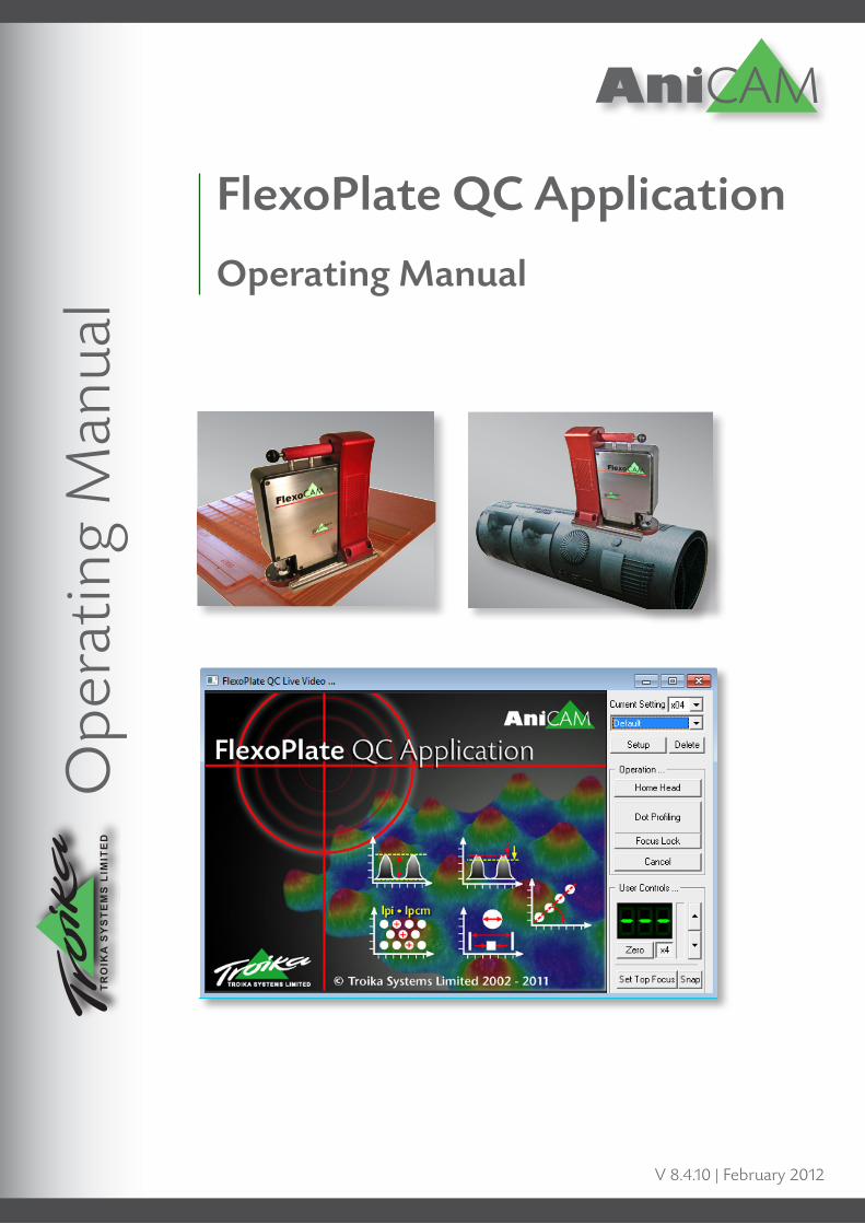
Image AnalysisThe Image Analysis functions/Icons are grayed out, if there is no image window on the screen. The functions can also be accessed by the icons.
1 Dot Information displays the taken readings and allows you to enter customer-specific information which will be printed with the readings in a report form.
The Dot Info window is accessible after the image is taken and contains all available data which can be printed on an Analysis report form. It allows you to manually enter your user name as well as customer and plate related information.
Depending on the measurement mode, some of the informa-tion is automatically generated. All other information will be filled in after you have taken the required readings.
The content of this window can be printed and/or exported to be used in other programs such as Excel (see Appendix 1 for further information).
The Layout Options entry in Options/Settings lets you choose a logo to be printed on the right top corner of the printout.

AniCAM FlexoPlate QC Application v8.4.x – Operating Manual
8
2. The Cross Section Analysis tool simulates a single electronic cut along a definable distance.
3. The 45° Area Analysis Tool allows you to define a square area in the image analysis window. Normally this area is positioned across 4 dots to check for the maximum depth between the dots (Dot Profiling Mode only).
4. The 3 Dot Profile Mode allows to measure the shape of 3 dots at the same time (Dot Profiling Mode only).
5. Calculate displays the Screen Ruling, an Angle Offset, Distance (Measure) between two definable points, the average Dot Spacing and Average Dot Diameter.
The Calculate window enables you to measure any distance between defin-able points. Simply click on one point and drag the mouse pointer to the second point. The result is immedi-ately displayed in the Measure field.
6. Dot Definition gives the user the opportunity to manually draw the shape of the dots, using either the Circle/ Ellipse, Polygon or the FreeForm drawing to manually calculate the line frequency and dot percentage and to transfer the value to the dot Info window and printable form by clicking in the corresponding button. Dot Definition is described in detail on pages 12 and 13.
ImportantTo achieve optimum Plate readings it is important to understand how the software works:
After the software is installed the first time, it provides no predefined setting for any kind of plate media. Therefore you have to create a setting for your media, which can be stored under a particular name for future readings of the same kind of media. If you want to read a flat flexo plate we recommend to put the plate onto a black carton. Some-times a different colour might improve the contrast.
Configuring a media means, that the system either automatically (or manually assisted) has to find and save the op-timum illumination settings for the radial and the coaxial light. When a setup is stored, the current zoom factor, 3D Profile stepping rate in µm and Dot Levelling enable/disable condition is also stored and recalled after selecting a stored name in the Setup field.
Image Analysis – continued

AniCAM FlexoPlate QC Application v8.4.x – Operating Manual
9
10. Manual focus adjustment
9. Head position
The FlexoPlate Camera WindowThe camera window can be switched on and off by clicking in the camera icon. The buttons and settings are described below.
Camera window in Measuring Mode
Camera window in Setup Mode
1. Mounted lens (needs x04)
4. Delete current setting
5. Move Head to home (surface) position
2. Selected setting
16. (Pre)set Top Focus position
15. Take a 2D snap
11. x4 speed for manual focus on/off
7. Start the 3D profiling
8. Cancel current operation
12. Moved distance in micron
13. Reset distance to Zero
3. Switch to Setup mode
In Setup Mode the camera window allows you to create a setting for a new plate media by offering certain adjustment and preset tools.
1. Select the optimum zoom setting
2. Light and exposure adjustments
3. Preset of the 3D step rate
5. Save the current settings
4. Level Dot Profiles adjusts the top of all dots to the same aver-aged vertical position (level) (see Appendix 4)
6. Lock focus to current position

AniCAM FlexoPlate QC Application v8.4.x – Operating Manual
10
FlexoPlate Reading Methods
3D Dot Profiling AnalysisStandard Dot Definition
The Dot Profiling Analysis can be used for a 3-dimensional dot examination and measure-ments of 1% to 30% dots.
The reliable Standard Dot Definition is used to manually define the dots.
Troikas Plate-Let powder helps to eliminate reflection issues.
Configuring the software for a particular mediaTo achieve the optimum readings it is important to understand how the system (software) works: After the software is installed the first time, it provides just Default settings for the different medias (plate, sleeve, film/mask).
These Default settings are not necessarily suited to measure every media. Therefore you should configure a particular media and store the configuration under a specific name for future readings.
When you store the settings, all current settings in the setup section of the camera window are also stored and recalled after selecting a stored name in the Setup drop down list. This procedure is described from page 11.
AniCAM FlexoPlate QC Application v8.4.x – Operating Manual
11
Step by step
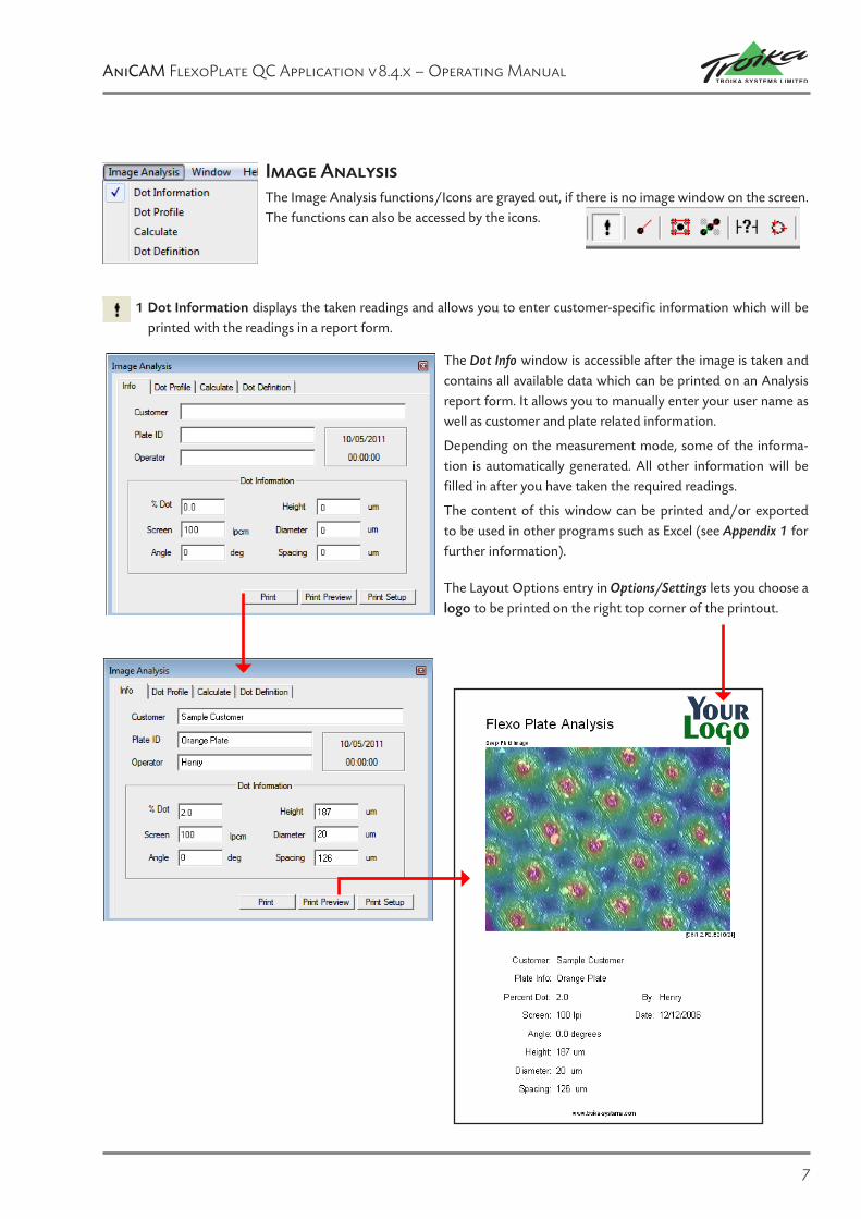
Finding and Saving a Setting
Once you have found the optimum Zoom and Light/Exposure settings to measure a particular plate media you can store the setting under a name, which can be recalled any time you want to measure the same kind of media again. In the follow-ing we describe how to find and save such a setting.
To adjust the system for a specific plate media you have to switch the camera window into the Setup Mode by clicking the Setup button.
Flat flexo plates should be placed onto a black carton. Put the Troika 3D-CAM onto the plate media and click the Home Head button to move the optics to the starting position.
The system needs between 9 and 16 dots in the window. Normally you know the frequency of your plate – so adjust the Zoom to the matching LPI. If you don’t know the frequency you might have to try different zoom levels until you see the desired number of dots. In example the plate dots have a frequency of 91 lpi – therefore we choose 85 - 110 in the window.
After homing the head, the result may not yet be in focus (as shown in the left sample).
You now have to adjust the focus and the settings for the coaxial and the radial light sources. Depending on the char-acteristics of the material this can be done automatically or must be done manually if there is too much reflection or not enough contrast.
When the Automatic Lighting box is checked, the system will automatically try to find the optimum settings for the exposure,the radial and the coaxial light.
Automatic lighting is checked for most materials.
If the Automatic Lighting box is not checked you can manu-ally adjust the light settings until you get a nice view of the dots top surface.
You can manually adjust the focus by clicking the focus up and down arrows.
If you click the x4 box, manual focus movements proceed with 4 times of the normal rate.
Once you have adjusted the focus to the top of the dots you must click the Set Top Focus button. The Autofocus then references to that defined position. (continued on next page)

AniCAM FlexoPlate QC Application v8.4.x – Operating Manual
12
Saving a settingOnce you have found the optimum setting for the zoom, the expo-sure, the radial and the coaxial light, you can now store it under a particular name. Click into the Save Settings button!
The new name can now be chosen from the Settings list in the camera window.
Step by stepFinding and Saving a setting – continued
Level dot profile (see also Appendix 4 – page 31 for a more detailed explanation)
Checking this function will vertically adjust all tops of the dots to the same averaged level.
A new window appears. Here you can choose whether you want to modify the settings of an existing name or to store the settings under a new name.
Click into the New button.
A new window appears and asks you to enter a name for the setting. In our sample we enter “orangeplate”.
Click into the OK button to get back to the normal operation.
without Levelling
with Levelling

AniCAM FlexoPlate QC Application v8.4.x – Operating Manual
13
Step by step
2-dimensional dot percentage readings
Note: The FlexoPlate QC Application offers two methods of analysing dot percentages and line frequencies: The 2D Analy-sis for measuring dot percentages (described here), and a 3D Dot Profile Analysis for more detailed information on the highlight dots from 1% to 30 % which is described in a separate section.
Before you take a reading we recommend that you set the system to Auto-Lighting and (if necessary) apply Troikas Plate-Let powder to compensate reflections as described on page 26.
To take a reading select the name stored for this media.
You can manually adjust the focus by clicking the focus up and down arrows.
If you click the x4 box, manual focus movements proceed with 4 times of the normal speed.
Once you have adjusted the focus to the top of the dots you must click the Set Top Focus button. The Autofocus then ref-erences to that defined position.
Note: You can always switch into the Setup Mode if you need to modify zoom or light settings!
Once you are satisfied with the result you can click into the Snap button to take a two-dimensional snap and transfer it to an analysis window.
After the image has been transferred into the analysis window the Dot Definition window appears:

AniCAM FlexoPlate QC Application v8.4.x – Operating Manual
14
Step by step2-dimensional dot percentage readings
Manual dot definition
The manual dot definition gives you the opportunity to manually redraw the shape of the dots, using either the FreeForm, the Polygon or the 3-Dot tool to calculate the percentage reading. A minimum of 3 objects must be drawn adjoining and tangential to each other to determine a reading, and allow the screen ruling calculation to be made.
You have three choices to define a dot shape:
1. Click the FreeForm button to draw along the dot shape.
2. Click the Polygon button to draw a polygon by clicking the “corners” of an angular shape (useful in the shadow area, when defining the mostly diamond-shaped non printing areas) .
3. Draw a circle by clicking at three points of the dots shape (mostly used - see following example).
1. You can see that there is a number (1) next to the cursor, telling that the software now expects you to define the first of the three positions. Move the mouse pointer to the first position and click. A red cross appears at the mouse position.
2. Before clicking the next position it is possible to move the red cross by the cursor and/or the up/down/left/right cursor keys.
3. Once the red cross is positioned correctly move the cursor to the next position (the number next to the cursor is now a “2”). Click on a new position to get the second red cross. Adjust it if necessary and then define the third position.
4. After the third position is defined the software automatically calcu-lates a circle and shows it on top of the dot. Also this circle can be moved by the cursor and/or cursor keys – and it can be resized and changed to a more elliptic shape.
5. Now you can either draw the shape of the next dot or copy the previ-ously created dotshape onto another dot by double-clicking into the center of this dot. Also the size, shape and position of the new dot can be changed.
6. The software needs 3 dot definitions to calculate the dot percentage and screen ruling.
After a third dot is defined, the FreeForm window shows the dot percentage and the screen ruling (screenshot next page).
(continued on next page)
1 2
3 4

AniCAM FlexoPlate QC Application v8.4.x – Operating Manual
15
Step by step2-dimensional dot percentage readings
After a third dot is defined, the FreeForm window shows the dot percentage and the screen ruling (screenshot below). Clicking into the Set button will transfer the readings to the printable info parameters.
• All objects can be moved by the cursor keys and/or the mouse pointer after being selected.• The TAB key automatically selects the next drawn object.• A drawn dotshape can be copied by dragging it while pressing the Ctrl-key.• Use the clear all box to remove all drawn objects.• If a (non-printing) hole is being described, it is necessary to click the objects define a hole checkbox.
Using the Zoom function (right mouse click) helps to draw around the dot more accurately when using the freeform func-tion.

AniCAM FlexoPlate QC Application v8.4.x – Operating Manual
16
Step by step
Dot Profiling
The Dot Profiling Mode is a method of viewing the profile of highlight dots from 1 to 30 %. It allows the operator to view and analyse the dots from the side electronically and therefore without cutting the media.
Note: Many (if not most) of the flexographic printing plates have a rather shiny and reflective surface. Depending on these characteristics it might be advisable to brush some Troika Platelet powder onto the surface which will lead to a far better reading than without the platelet powder (see page 25 for detailed information). When using the powder we recommend to place the plate onto a black carton.
How does Dot Profiling work?The 3D CAM takes a series of pictures (each with a different focus depth) down to the ground level of the plate. The soft-ware then removes all unsharp parts of each level and combines the levels to a rendered 3D grid model, which can then be analysed and rotated in any direction.
Taking a Dot Profiling readingIn our example we will measure a 1% field of a flexo plate. Such small dots normally cannot easily be identified in a two-dimensional analysis. As with all other measuring methods we recommend saving the settings for a media once the zoom and other settings are determined. We place the 3D CAM onto a 1% field on our plate media.
We then adjust the Zoom to the correct setting (9 to 16 dots should be covered).
The lighting should be set to Automatic.
Then we adjust the focus to the top of the dots by (after homing the head) clicking the arrow-buttons. Once the image is in focus we click the Focus Lock button.
Before saving the setting you can assign the Z-Scan Resolution. The software takes this value as the stepping distance be-tween the level-pictures.
Activating the dot profile levelling results in a software based averaged raise of the dots to the same vertical height (for rea-dings on round media like sleeves – see Appen-dix 4).
The system always takes 250 pictures down the surface – each with a different focus depth. Changing the stepping rate therefore affects the maximum scanning depth:
1µm : 200 µm depth | 2 µm : 400 µm depth | 4 µm : 800 µm depth
Select your preferred Stepping rate and click the Save Settings button.

AniCAM FlexoPlate QC Application v8.4.x – Operating Manual
17
Step by step Dot Profiling
Saving the Setting
After the basic settings have been defined, they must be saved prior to start the dot profiling.
Click the Save Settings button.
Click the New button to enter a new name.
Enter a name and click the OK button. The new name appears selected in the Setup dropdown list of the camera window.
Click in the Dot Profiling button to start the sequence.
You will see that the system now re- adjusts the auto-lighting and then starts to take the 250 pictures down the material.
If not terminated by hitting the space bar, the software takes the maximum of 250 pictures. You can manually terminate the routine when all elements displayed in the camera window are out of focus. After ana-lysing the bitmaps the image is displayed in a new window.
Fade and Zoom SlidersA right mouseclick on the image brings up a slider window. The Fade slider lets you fade from the greyscale view into the level colour view, were different dot heights are displayed as different colours.
A scale on the left and top side of the window informs about the field of view dimensions (see next page).
When the Fade slider is at 0%, the image shows the elements reflecting the coaxial light only.
When the Fade slider is at 50%, the image shows all calculated elements in focus..

AniCAM FlexoPlate QC Application v8.4.x – Operating Manual
18
Step by step
Dot Profiling
If you move the Fade slider beyond 50%, the greyscale colour is replaced by the level colour. The colour chosen by the Fade Slid-er also affects the 3D display of the dots.
Image Analysis – Dot Info
The Dot Info window appears after a dot profiling image is transferred and contains all currently available data. It allows you to manually enter customer and plate related information and your user name.
Some of the information is automatically generated. Other information will be filled in after you have taken the required manual readings. The content of this window can be printed and/or exported to be used in other programs such as Excel (see Appendix 1 for detailed export information). We will come back to the Dot Info window after we have taken some more readings.

AniCAM FlexoPlate QC Application v8.4.x – Operating Manual
19
Step by step – Dot Profiling
Image Analysis – Dot ProfileWhen you switch to the Dot Profile section of the Image Analysis window, you can choose between three tools: Cross Sec-tion Analysis tool for single cuts, 45° Area Analysis tool and a 3-Dot Profile tool which allows to measure the screen count and dot percentage.
Cross Section Analysis Tool
45° Area Analysis ToolThis tool allows you to draw a Square area onto the image window. Simply click into the center of the area you want to measure and drag your mouse pointer outwards. Depending on your mouse movement the area will grow, shrink and/or rotate accordingly. In our example we now scale and position the area so that the green and yellow axes cover 4 dots.
The Dot Profile window now shows a side view of the cut along the yellow and green axis.
All analysis tools can be deleted from the image by pressing the Delete-key.
The Cross Section Analysis tool acts like an electronic knife.
The cutting length is de-fined by simply clicking and dragging the mouse pointer.
As with all other tools distance and angle readings can directly be taken in the graph (click and drag).

AniCAM FlexoPlate QC Application v8.4.x – Operating Manual
20
Step by step
Dot Profiling – 45° Area Analysis Tool
Taking a reading in the graphYou can take readings inside the graph. Just click and drag from one position to another position. The system will display the distance and the angle. In the left example we measured the depth between the top of the dots and the relief depth be-tween the dots.
After clicking into the Average> button the system shows a graph with an averaged result (see next page).The graph shows the averaged result of the 45° area analysis tool.
The top red line represents the manually defined top surface position of the plate. The dashed line represents a manually defined dot compression and the lower red line represents the lowest level found by the software.
All manual settings can be changed in Options/Settings.
Clicking in the 3D button switches to the 3D View of the de-fined area. The view can be zoomed in and rotated in the X and Y direction by using the corresponding sliders.
(continued on next page)
Zoom slider horizontal rotation
vertical rotation
The Level button can be used to adjust the tops of the dots to the same (averaged) top position. The levelling function is described in Appendix 4 on page 31

AniCAM FlexoPlate QC Application v8.4.x – Operating Manual
21
Step by step
Dot Profiling3-Dot Profiling Tool
This tool allows you to measure three dots at the same time. First select the tool icon. Then click into the center of one dot and drag the pointer to a neighbour dot. Fine-tuning the position can also be done by the cursor keys. You
can rotate the tool with the Cursor keys while pressing the Ctrl-key.
The graph shows the cuts along the yellow and green axes. The following enlargement explains the relations between the views.
(The shown triangles and arrows are drawn for reference in this manual and cannot be seen on the monitor.)1
1
2
3
3
1
2

AniCAM FlexoPlate QC Application v8.4.x – Operating Manual
22
Step by step
Dot Profiling – 3-Dot Profiling Tool
Averaged Display of the Profiles
After clicking in the Average>> button the window shows an averaged version of the 2 views shown in the previous window (see previous page).
The window also shows the following information:
1. Calculated screen count
2. The calculated dot percentage at the Top Surface position, represented by the top red line (manu-ally defined in the settings)
3. The calculated dot percentage at the Dot Com-pression position, represented by a dashed line (manually defined in the settings)
4. The lowest ground level found by the software is represented by the red line at the bottom of the window. (It can nicely be seen that the depth between dots is less deep than the maximum depth).
Clicking into the 3D>> button takes you to the 3D representation of the 3 dots covered by the tool.
(see next page)
By clicking the Set button the Screen Count value and the Top Dot percentage are transferred to the Dot Info section and can be printed together with the other measurements and information.
Printable Analysis Report Form
FlexoCAM AnalyseBlack Plate
[C6/8.4,R15,E140/16,x4/1]
Customer: Sample customer
Plate Info: Black Plate
Operator: Henry
Date: 05/04/2011
Percent Dot: 1.0
Screen Count: 54 lpcm
Screen Angle: 60.0 degrees
Height: 56 um
Diameter: 16 um
Spacing: 180 um
www.troika-systems.com
FlexoPlate Analysis

AniCAM FlexoPlate QC Application v8.4.x – Operating Manual
23
Step by step
Dot Profiling – 3-Dot Profiling Tool
Different readings in the graph display
measuring the dot diameter at the defined Top Surface Measuring the depth of a space between dots
measuring the dot diameter at the defined compression Measuring the angle of a dot shape

AniCAM FlexoPlate QC Application v8.4.x – Operating Manual
24
Step by step
Dot Profiling – 3-Dot Profiling Tool
3D Viewing
The 3D view always shows the dots covered by the current tool – in this case the 3-Dot Profiling tool. The 3D view can be zoomed and rotated in the X and Y direction.
You can also view a 3D representation of the whole image. In this case you must delete all previously drawn tools by select-ing the tool and hitting the Delete-key. Then - being in the 3D view mode – just click once on the image.
Here you can see some variations of 3D views of our sample plate.
Zoom slider horizontal rotation
vertical rotation

AniCAM FlexoPlate QC Application v8.4.x – Operating Manual
25
FlexoPlate Dot Profiling with Platelet Powder
IlluminationFor the camera to produce a 2D or 3D view of the substrate it is essential that the material to be analysed can be “seen” optically at each depth of image that is being taken. This has been one of the enduring problems for any company involved with the analysis of Flexo plates.
Flexo plates ad sleeves come in a variety of materials and colours. Each material has a different amount of reflectance to the light that is used to illuminate the halftone dots on the plate. The correct illumination of the plate is essential, and requires two light sources, co-axial and radial targeted at the halftone dots at the correct angles for optimum illumination – this is automatically set when using the AniCAM Camera.
However the reflectance from the majority of plate materials make them unsuitable for 3D analysis. The solution had to be non toxic, non-fluid that could not damage the plate in any way. What was needed was a method of applying an almost transparent, sheer, thin film over the halftone dots that does not distort the 3D profile and allowed an accurate represen-
tation of the dot to be analysed.
Plate-Let PowderTroika researched for a non-hydroscopic, white, low reflectance powder that would lie evenly over the shape of the dots on the large range of flexo plate materials on the market. Eventually a suitable powder was found. This powder is flat and wide in structure, the width is typically less than 3 microns and the depth is sub-micron, so it will naturally lie flat onto the plate material.
It is applied from the nozzle of a small plastic bottle. The user sprays a fine coating onto the plate and brushes the “plate-let” powder into the plate. The whole process takes a few seconds.
A patent for the use of the ‘Plate-Let Powder’ in this application has been applied for.
At first the user may be tempted to use too much powder, which can be seen when viewing the dot with the AniCAM Camera, but very quickly learns the smallest amount of powder is needed.
Easy to apply
Conclusion
The “Plate-let Powder” improves the visability of the dots for the FlexoPlate QC application. The ability to electronically inspect the dots in profile is simple, informative and non-destructive.
From its data it is possible to check for screen count, dot percentage, the plate relief and the relief between the dots. More important it is now possible to estimate the dot gain by simulating the compression of the press onto the plate material and get a good indication of what over or under compression will do to the final printed result.
The next page shows a comparison between plate images taken with and without the Troika Plate-let powder

AniCAM FlexoPlate QC Application v8.4.x – Operating Manual
26
Comparison between a non powdered (left images) and a powdered plate reading (right images)
The Platelet powder eliminates the reflections
Reflections lead to wrong interpretations

AniCAM FlexoPlate QC Application v8.4.x – Operating Manual
27
Appendix 1: Export Info
All Info data can be exported to be used and further analysed in a 3rd party software like Excel. The number of exported records equals the number of currently open image windows and therefore taken readings. To export the info entries simply execute the Command Export Info... under the File menu.
A new window appears were you select the individual readings you want to
include in the export as well as their arrangement.
The Delimiter window allows you to choose the Field- and Record Separators, which can be inter- preted in the external software.
Export formats Top to bottom and Left to right
The difference between the export formats top to bottom and left to right can be seen in the left examples.

AniCAM FlexoPlate QC Application v8.4.x – Operating Manual
28
Appendix 2: X/Y CalibrationTo calibrate a distance you need the optional Troika Plexiglass calibration plate or an adequate scale with a 1/100mm grid or ruler. Please be aware that each lens/zoom setting combination must be calibrated individually.
The Troika Calibration plate provides a round 1/100 mm grid (see arrow). Place the camera lens above this grid area.
The camera window shows the grid structure.
Adjust the focus by clicking the two up/down focus arrow buttons.
Click the Snap-button to transfer the image to the image analysis window.
Measure a distance on the image window by clicking onto the starting position and dragging the crossline onto the destination (keep the mouse button pressed). The distance is displayed in the Measure tab of the Image Analysis window
– in our example 797 micron. It should be 800 – therefore we need to calibrate.
(continued next page)

AniCAM FlexoPlate QC Application v8.4.x – Operating Manual
29
Appendix 2: X/Y Calibration – continued
To calibrate the distance click the Calibrate button. The Tool Measure dialog window appears. Enter the correction value – in our example 800.
Confirm the window by clicking the OK-button.
Perform another distance reading to verify the correct calibration.
Important: A Calibration affects only the currently active lens/zoom factor combination. Therefore we recommend to also check the other combinations if appropriate.

AniCAM FlexoPlate QC Application v8.4.x – Operating Manual
30
Appendix 3: Anti-Vibration SensitivityAn Anti-Vibration sensitivity setting can be selected to improve cam-era reading consistency during operation under less optimal work-ing conditions, whereby vibrations from the immediate environment have the potential to influence AniCAM readings.
The Anti-Vibration Sensitivity setting is located under Options/Set-tings.
Vibrations detected by the camera are high-lighted in the camera window by a yellow border (left example) shown during the cell profiling operation – vibrations are not al-ways perceptible or visible to the eye).
There are 4 levels of anti-vibration strength to chose from:
Off: Anti-vibration disabled.
Low: For typical use in poor working environments.
Medium: For typical use in shop floor environments (default).
High: For typical use in laboratory environments.

AniCAM FlexoPlate QC Application v8.4.x – Operating Manual
31
Appendix 4: Levelling of dotsThe FlexoPlate QC Software offers two alternatives to level dots. The first alternative should be used if the measurement is taken on a round material with a relatively small diameter. In this case the levelling is applied during the dot profiling process (3D scanning). It can be activated by checking the corresponding box in the Setup section of the camera window. A deviance conditioned by the curvature of the media can be compensated this way.
The second (independent from the first) alternative offers the Level button at the bottom of the dot profiling window. This button allows to measure the dot percentage under the simulation that the tops of all dots are vertically adjusted to the same average height. The following two examples show the implication of such a levelling.
No Levelling
The left screenshot shows an unlevelled graphical representation of three dots. The very right dot is not even touching the graphs top surface position (red line).
With activated Levelling
After applying levelling by clicking the Level button, the height and top position of each dot is adjusted and averaged.

AniCAM FlexoPlate QC Application v8.4.x – Operating Manual
32
Appendix 4: Levelling of dots
Special Geometric ReadingsFor special geometric readings like the die cut plate shown below it is essential to switch Levelling off.
In this case levelling would result in a distortion of the shape.

AniCAM FlexoPlate QC Application v8.4.x – Operating Manual
33
Appendix 5: Safely Parking the camera headAfter finishing all readings the camera should be safely placed back into the protecting black AniCAM box. It is absolutely necessary and important that the camera head (black moving body part of the camera) has been electronically moved to its home position – allowing to lock it using the lock pin at the top of the camera body.
This is especially necessary after measuring rolls with a relatively small diameter because in this case the camera body needs to be moved much higher than when reading rolls with a higher diameter.
Never try to manually push the camera body down in order to lock it. Always use the Park Head command to move the camera body down electronically! You can damage the internal mechanics.
The Park Head function can be found under the Option menu. It moves the camera body to its home position, so the transport lock can be engaged. Prior to parking, the camera must be placed on a flat surface (follow the on-screen instructions). The but-ton is greyed if there is no camera attached or camera window open.
Before you can start the Head Parking by clicking the Park but-ton, you must place the AniCAM on a flat surface (table), so it can move the black body down com-pletely.
After clicking the Park button a message informs you about the status:
After the parking is completed you will get a message to lift the head and to engage the lock pin.
The camera window will close down automatically.
Then click the Done button
The head is parked safely.
NEVER

AniCAM FlexoPlate QC Application v8.4.x – Operating Manual
34
Appendix 6: AniCAM Battery Pack (Option) u Greater portability
u Simplified handling
u Intelligent Battery Management
u Long operating capacity (up to 8 hours typical use)
u Quick Charging (approx. 2 hours)
u Simple retrofit
The AniCAM Battery Pack is an intelligent power manage-ment system designed specifically for use with the Troika range of 3D measurement units“. The Battery Pack frees your sys-tem from the necessity of a permanent connection to an ex-ternal power supply during readings.
The Battery Pack is not just a simple cell, it houses an intelligent control system and the logic is designed to extend the life of the cells. The charging process is controlled by a programmed computer chip which helps to protect against overcharging and also reducing the likelihood of overheating during continuous use.
As soon as the 12v cable is connected to
the battery pack, the cells (if required)
will be charged regardless the On/Off
switch position.
The AniCAM can be operated both ways: Battery mode only and in Charging Mode.
Off On
12V
Condition Amber (DC) Green (BAT)
At Power Up (1 second) Hi speedflashing
Hi speedflashing
No DC Input (<9v) Off - - -
Low DC Input (9v - 11v) Flash - - -
Good DC Input (>11v) On - - -
No Battery (<7.6v) - - - Off
Charging (Good DC in) On Flash
Low Battery (No DC in) Off Flash
Charged - - - On
Temperature Violation alt. 1 sec Flash
alt. 1 sec Flash
Two LEDs indicate the operating status of the system
December 2011, E&OE. – Specifications and details subject to change without notice

AniCAM FlexoPlate QC Application v8.4.x – Operating Manual
About FlexoPlate QC
The About information is accessible through the Help icon in the main menu bar, or by pressing the Troika company logo below the Colour Selection.
1 Blackworth Court, Blackworth Industrial Estate
Highworth Wilts SN6 7NS United Kingdom
Tel: +44 (0) 1793 766355 Fax: +44 (0) 1793 766356
©Troika Systems Limited 2011 • www.troika-systems.com