Embed Size (px)
Citation preview

MigWeld 140 140 AMP MIG Welder
Page 1 of 27
Operating Manual
For
MigWeld 140
140AMP Transformer MIG Welder 110v

MigWeld 140 140 AMP MIG Welder
Page 2 of 27
Table of Contents:
PG. 3: Thank you From LONGEVITY
PG. 4-6: Warranty/Shipping Damage/Order Information
PG. 7-9: Warning and Safety Information
PG. 10: General Description
PG. 11: Specifications and Ratings
PG. 12-16: Safety Precautions
PG. 17: Unpacking
PG. 18: Components and Controls
PG. 19-23: Installation
PG. 23-24: Welding Operations
PG. 25: Suggested Settings
PG. 26: Overload Protection
PG. 27: Enjoy your new welding machine from LONGEVITY!

MigWeld 140 140 AMP MIG Welder
Page 3 of 27
THANK YOU! We, at LONGEVITY, want to thank you for purchasing our product. You are almost ready to
experience Longevity Welding first hand. Longevity definitely appreciates your business and
understand that this equipment may be overwhelming to setup and operate so we have
prepared a manual that will assist you in understand your new plasma cutter/welder. If you
have any questions during or after reading this manual, please feel to contact us! Please
take a moment to register your product on our website at www.longevity-inc.com or
www.lweld.com
Once again, thank you for choosing Longevity as your main welding supplier!

MigWeld 140 140 AMP MIG Welder
Page 4 of 27
Longevity Global, Inc.
23591 Foley St
Hayward, CA 94545
Toll-Free Customer Support: 1-877-LONG-INC / 1-877-566-4462
Website: www.longevity-inc.com
Sales: [email protected]
Customer Service: [email protected]
Dealers: [email protected]
Complaints: [email protected]
Please join our welding forums to share welding tips and tricks, to receive useful information
from customers who also use our products, and to be a part of the Longevity™ welding
community at www.freeweldingforum.com
Check out LONGEVITY Racing at www.longevity-racing.com

MigWeld 140 140 AMP MIG Welder
Page 5 of 27
Warranty
LONGEVITY Plasma Cutters, Welders, and Multi-Purpose Welders are covered for specific
Parts and Labor warranty at our facility. For detailed information regarding your specific
LONGEVITY welder or cutter, please view our Terms and Policies page on our website at
the following website link: http://www.longevity-inc.com/terms/
Shipping Damage
Your machine is insured against damage during shipping. Keep all packing materials and
containers in case machine must be returned. We will initiate a claim with the shipping
company to cover damage or loss. If there is shipping damage upon opening your package,
our customer service team will work with you to get the matter resolved.
In Warranty Service
Customers, who own machines that are in warranty and require service, should contact our
Warranty Department by email at [email protected] to obtain a return authorization
code. In addition to the warranty we offer, we would like for you to register your product on
our website at www.longevity-inc.com/resources. Remember, warranty starts from the date of
purchase. For your convenience, write your order information below so you can track your
order in case you need warranty work.
Order No.: _________________________________
Date of Purchase: _____________________________
Warranty Period: ______________________________

MigWeld 140 140 AMP MIG Welder
Page 6 of 27
Out-of-Warranty Service
Customers, who own machines that are out of warranty and require service, should contact us
for an estimate. Longevity offers an exchange program on out of warranty units. We also help
non LONGEVITY customers with repairs, replacement, and service.
If your unit is not manufactured by Longevity and you cannot receive service from your
manufacturer or seller, Longevity will lend out hand. Our warranty policy is also available for
all plasma cutters and welders. For more information, please email us at
MigWeld 140 140 AMP MIG Welder
Page 7 of 27
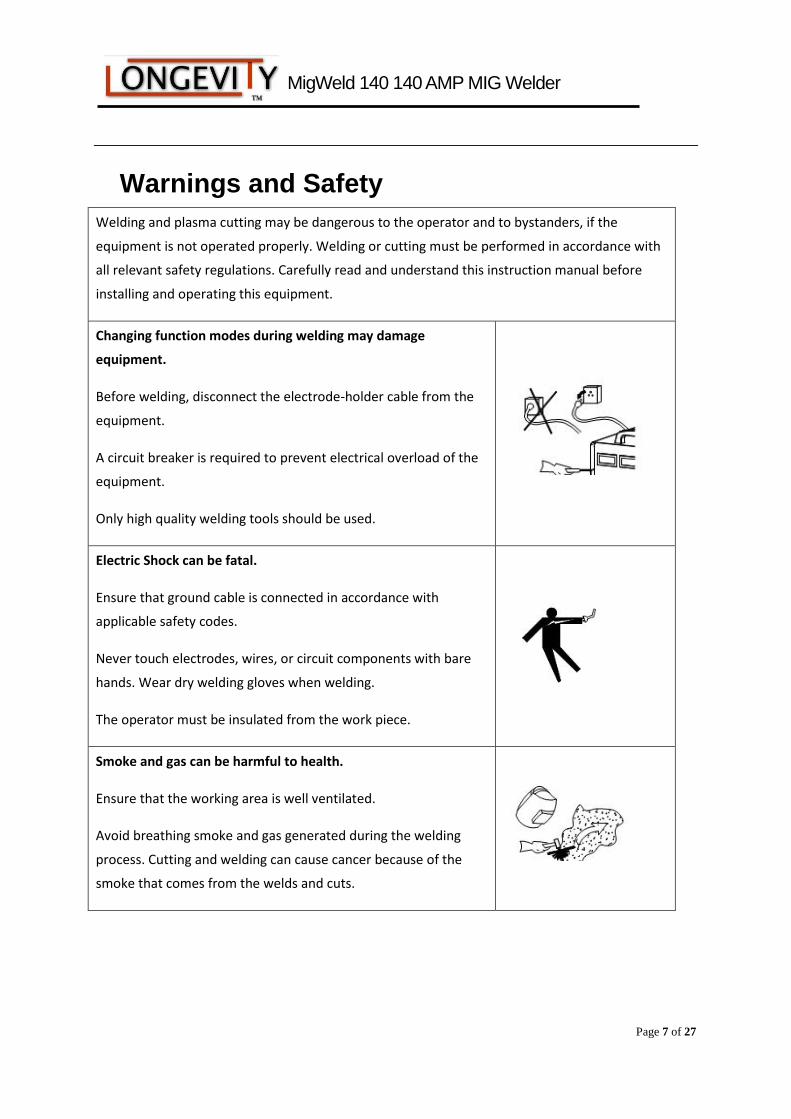
Warnings and Safety
Welding and plasma cutting may be dangerous to the operator and to bystanders, if the
equipment is not operated properly. Welding or cutting must be performed in accordance with
all relevant safety regulations. Carefully read and understand this instruction manual before
installing and operating this equipment.
Changing function modes during welding may damage
equipment.
Before welding, disconnect the electrode-holder cable from the
equipment.
A circuit breaker is required to prevent electrical overload of the
equipment.
Only high quality welding tools should be used.
Electric Shock can be fatal.
Ensure that ground cable is connected in accordance with
applicable safety codes.
Never touch electrodes, wires, or circuit components with bare
hands. Wear dry welding gloves when welding.
The operator must be insulated from the work piece.
Smoke and gas can be harmful to health.
Ensure that the working area is well ventilated.
Avoid breathing smoke and gas generated during the welding
process. Cutting and welding can cause cancer because of the
smoke that comes from the welds and cuts.
MigWeld 140 140 AMP MIG Welder
Page 8 of 27
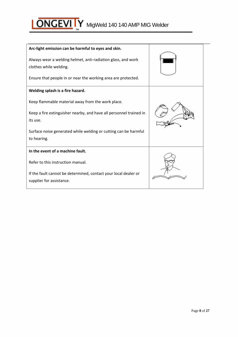
Arc-light emission can be harmful to eyes and skin.
Always wear a welding helmet, anti-radiation glass, and work
clothes while welding.
Ensure that people in or near the working area are protected.
Welding splash is a fire hazard.
Keep flammable material away from the work place.
Keep a fire extinguisher nearby, and have all personnel trained in
its use.
Surface noise generated while welding or cutting can be harmful
to hearing.
In the event of a machine fault.
Refer to this instruction manual.
If the fault cannot be determined, contact your local dealer or
supplier for assistance.
MigWeld 140 140 AMP MIG Welder
Page 9 of 27
Safety Tips
Consider the following tips to ensure safe operation of your welding/cutting equipment:
Ensure that this welding equipment is installed in an area free of corrosive chemical
gases, flammable gases or materials, and explosive chemicals.
The area should contain little dust, and have a humidity of no more than 80%.
Operate the welding equipment in an area sheltered from direct sunlight and precipitation.
Work area temperature should be maintained at - to
If, because of an overload, the machine suddenly stops, and it is necessary to restart it,
leave the internal fan operating to lower the inside temperature.
Always wear protective clothing and a welding mask to protect your skin.
Wear safety goggles designed to darken the arc generated by your machine.
Wear suitable noise protection to protect your hearing.
Ensure that machine is grounded through the power cord or on the machine case.
Never operate the machine in bare feet or on a wet floor.
Never switch the machine off while it’s in use. Doing so will damage the internal
circuitry.
Ensure that your circuit breaker is rated to handle the current requirements of your
machine.
Use a UL approved receptacles and plugs with your machine. Never hard wire the
machine to main power.
Work in a well-ventilated area to avoid smoke. Keep your head out of the smoke. Ensure
that air is flowing away from you to avoid inhaling smoke.
Ensure proper ventilation through the machine’s louvers. Maintain a distance of at
least 12 inches between this cutting equipment and any other objects in the work area.
Use a screen or curtain designed to keep passer byes from viewing the arc.
The arc spray and metal spray from machine use may cause nearby fires. Use caution.
If, after reviewing this manual, you have any problems in setting up or operating your
machine, contact us at [email protected].

MigWeld 140 140 AMP MIG Welder
Page 10 of 27
General Description:
The LONGEVITY MIGWELD 140 welder delivers industrial quality and
performance at an affordable price. Perfect for the beginner and the
professional. The MIGWELD 140 is the most versatile welder which will do
aluminum with the optional spool gun in addition to all exotic metals. The
MIGWELD 140 will easily connect to your existing 110v wall outlet and can
be setup easily in minutes. Running on a standard 110v power cord, which is
included, you will be able to lay down a nice weld anywhere.
MigWeld 140 140 AMP MIG Welder
Page 11 of 27
Operation Manual
Carefully read the operation manual prior to using, installing and maintaining
the electric welding machine for the purpose of preventing damages such as fire,
electric shock and etc from occurring. Please keep the manual for the reference
in the future.
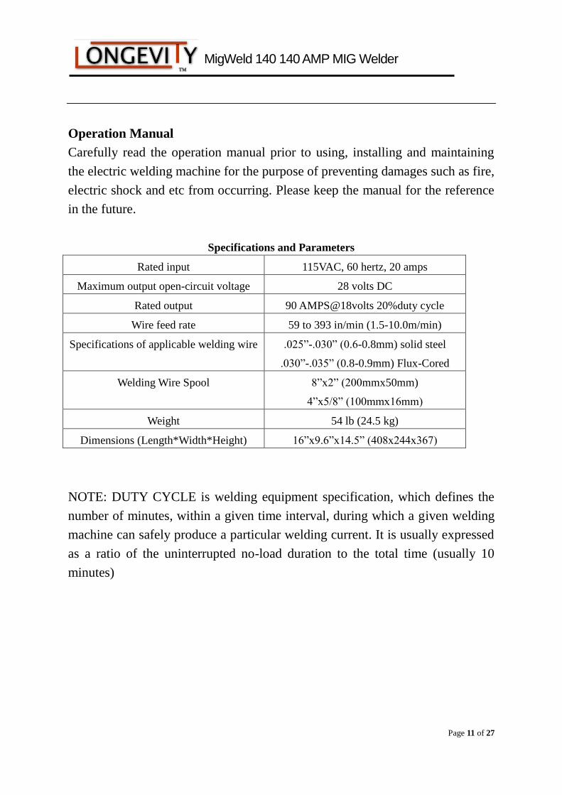
Specifications and Parameters
Rated input 115VAC, 60 hertz, 20 amps
Maximum output open-circuit voltage 28 volts DC
Rated output 90 AMPS@18volts 20%duty cycle
Wire feed rate 59 to 393 in/min (1.5-10.0m/min)
Specifications of applicable welding wire .025”-.030” (0.6-0.8mm) solid steel
.030”-.035” (0.8-0.9mm) Flux-Cored
Welding Wire Spool 8”x2” (200mmx50mm)
4”x5/8” (100mmx16mm)
Weight 54 lb (24.5 kg)
Dimensions (Length*Width*Height) 16”x9.6”x14.5” (408x244x367)
NOTE: DUTY CYCLE is welding equipment specification, which defines the
number of minutes, within a given time interval, during which a given welding
machine can safely produce a particular welding current. It is usually expressed
as a ratio of the uninterrupted no-load duration to the total time (usually 10
minutes)
MigWeld 140 140 AMP MIG Welder
Page 12 of 27
SAFETY WARNINGS AND PRECAUTIONS
WARNING: When using welder, basic safety precautions should always be followed to
reduce the risk of personal injury and damage to equipment.
Read all instructions before using this welder.
Keep work area clean. Cluttered areas invite injuries.
Observe work area conditions. Do not use machines or power tools in damp or wet locations. Don’t
expose to rain. Keep work area well lighted. Do not use electrically powered tools in the presence of
flammable gases or liquids.
Keep children away. Children must never be allowed in the work area. Do not let them handle machines,
tools or extension cords.
Store idle equipment. When not in use, tools must be stored in a dry location to inhibit rust. Always lock
up tools and keep them out of the reach of children.
Do not force tool. It will do the job better and more safely at the rate for which it was intended. Do not use
inappropriate attachments in an attempt to exceed the tool capacity.
Use the right tool for the job. Do not attempt to force a small tool or attachment to do the work of a larger
industrial tool. There are certain applications for which this welder was designed. Do not modify this
welder and do not use this welder for a purpose for which it was not intended.
Dress properly. Do not wear loose clothing or jewelry as they can be caught in moving parts. Protective,
flame retardant, electrically non-conductive cloths and non-skid footwear are recommended when working.
Wear restrictive hair covering to contain long hair.
Use eye and ear protection. Always wear ANSI approved,
arc shaded, impact safety face shield (welding helmet). Always
use a full-face shield when welding. Always wear ANSI approved
eyewear under face shield and while in the workplace. Wear a
NIOSH approved dust mask or respirator when working around
metal, chemical dusts, fumes and mists.
Do not over reach. Keep proper footing and balance at all times. Do not reach over or across running
machines.
Maintain tools with care. Keep tools sharp and clean for better and safer performance. Follow instructions
for lubricating and changing accessories. Inspect tool cords periodically and, if damaged, have them
repaired by an authorized technician. The handles must be kept clean, dry, and free from oil and grease at
all times.
Disconnect power. Unplug tool when not in use.
Remove adjusting keys and wrenches. Check that keys and adjustment wrenches are removed from the
welder and work area before plugging in.
Avoid unintentional starting. Be sure the switch is in the off position when not in use and before plugging
in. Do not carry any tool with your finger on the trigger, whether it is plugged in or not.
Stay alert. Watch what you are doing. Use common sense. Do not operate any tool when tired.
MigWeld 140 140 AMP MIG Welder
Page 13 of 27
Check for damaged parts. Before using any tool, any part that appears damaged should be carefully
checked to determine that it would operate properly and perform its intended function. Check for alignment and
binding of moving parts; any broken parts or mounting fixtures; and any other condition that may affect proper
operation. Any part that is damaged should be properly repaired or replaced by a qualified technician. Do not
use the tool if any switch does not turn on and off properly.
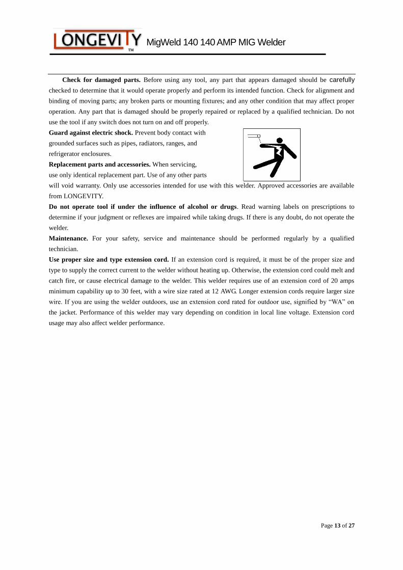
Guard against electric shock. Prevent body contact with
grounded surfaces such as pipes, radiators, ranges, and
refrigerator enclosures.
Replacement parts and accessories. When servicing,
use only identical replacement part. Use of any other parts
will void warranty. Only use accessories intended for use with this welder. Approved accessories are available
from LONGEVITY.
Do not operate tool if under the influence of alcohol or drugs. Read warning labels on prescriptions to
determine if your judgment or reflexes are impaired while taking drugs. If there is any doubt, do not operate the
welder.
Maintenance. For your safety, service and maintenance should be performed regularly by a qualified
technician.
Use proper size and type extension cord. If an extension cord is required, it must be of the proper size and
type to supply the correct current to the welder without heating up. Otherwise, the extension cord could melt and
catch fire, or cause electrical damage to the welder. This welder requires use of an extension cord of 20 amps
minimum capability up to 30 feet, with a wire size rated at 12 AWG. Longer extension cords require larger size
wire. If you are using the welder outdoors, use an extension cord rated for outdoor use, signified by “WA” on
the jacket. Performance of this welder may vary depending on condition in local line voltage. Extension cord
usage may also affect welder performance.
MigWeld 140 140 AMP MIG Welder
Page 14 of 27
WARNING: The warnings, cautions and instructions discussed in this instruction
manual cannot cover all possible conditions and situations that may occur. It must be
understood, by the operator, that common sense and caution are factors, which cannot
be built into this product, but must be supplied by the operator.
ARC WELDER SAFETY WARNINGS AND PERCAUTIONS
Warning: This product, when used for welding and similar applications, produces
chemicals to cause cancer and birth defects (or other reproductive harm).
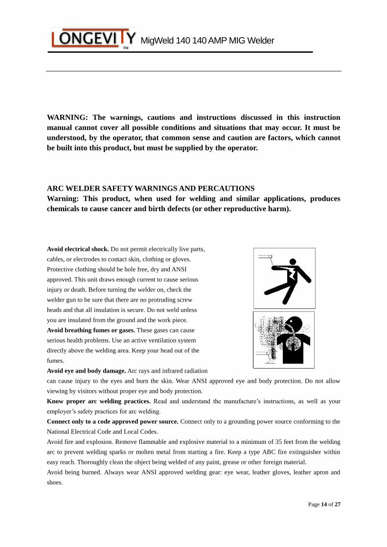
Avoid electrical shock. Do not permit electrically live parts,
cables, or electrodes to contact skin, clothing or gloves.
Protective clothing should be hole free, dry and ANSI
approved. This unit draws enough current to cause serious
injury or death. Before turning the welder on, check the
welder gun to be sure that there are no protruding screw
heads and that all insulation is secure. Do not weld unless
you are insulated from the ground and the work piece.
Avoid breathing fumes or gases. These gases can cause
serious health problems. Use an active ventilation system
directly above the welding area. Keep your head out of the
fumes.
Avoid eye and body damage. Arc rays and infrared radiation
can cause injury to the eyes and burn the skin. Wear ANSI approved eye and body protection. Do not allow
viewing by visitors without proper eye and body protection.
Know proper arc welding practices. Read and understand the manufacture’s instructions, as well as your
employer’s safety practices for arc welding.
Connect only to a code approved power source. Connect only to a grounding power source conforming to the
National Electrical Code and Local Codes.
Avoid fire and explosion. Remove flammable and explosive material to a minimum of 35 feet from the welding
arc to prevent welding sparks or molten metal from starting a fire. Keep a type ABC fire extinguisher within
easy reach. Thoroughly clean the object being welded of any paint, grease or other foreign material.
Avoid being burned. Always wear ANSI approved welding gear: eye wear, leather gloves, leather apron and
shoes.
MigWeld 140 140 AMP MIG Welder
Page 15 of 27
WARNING ARC WELDING CAN BE HAZARDOUS
WARNING: THIS WELDING MACHINE MUST BE CONNECTED TO POWER SOURCE IN
ACCORDANCE WITH LOCAL ELECTRICAL CODES
WARNING: DISCONNECT POWER SOURCE BEFORE DISASSEMBLY OF THE TORCH
WARNING: THE SHIELD NOZZLE MUST BE INSTALLED PRIOR TO OPERATION OF THE TORCH
WARNING: ALL INSTALLATION, MAINTENANCE, REPAIR OPERATION OF THIS EQUIPMENT
SHOULD BE PREFORMED BY QUALIFIED PERSONS ONLY IN ACCORDANCE WITH NATIONAL,
STATE AND LOCAL CODES ELECTRIC SHOCK CAN KILL.
Improper use of electric arc welders can cause electric shock, injury and death! Take all precautions described in
this manual to reduce the possibility of electric shock.
The MigWeld140 power switch is to be in the OFF (“O”) position when installing work cable and gun and when
connecting power cord to input power.
Always wear dry, protective clothing and welding gloves and insulated footwear.
Always operate the welder in a clean, dry, well-ventilated area. Do not operate the welder in humid, wet, rainy
or poorly ventilated areas.
Be sure that the work piece is properly supported and grounded prior to beginning the electric arc welding
operation.
The electrode and work (or ground) circuits are electrically “hot” when the welder is on. Do not touch these
“hot” parts with your bare skin or wet clothing.
Ground the work or metal to be welded to a good electrical (earth) ground.
FUMES AND GASES can be dangerous.
Do not breathe fumes that are produced by the arc welding operation. These fumes are dangerous.
Keep the head and face out of the welding fumes.
Shielding gases used for arc welding can displace air and cause injury or death. Always use enough ventilation.
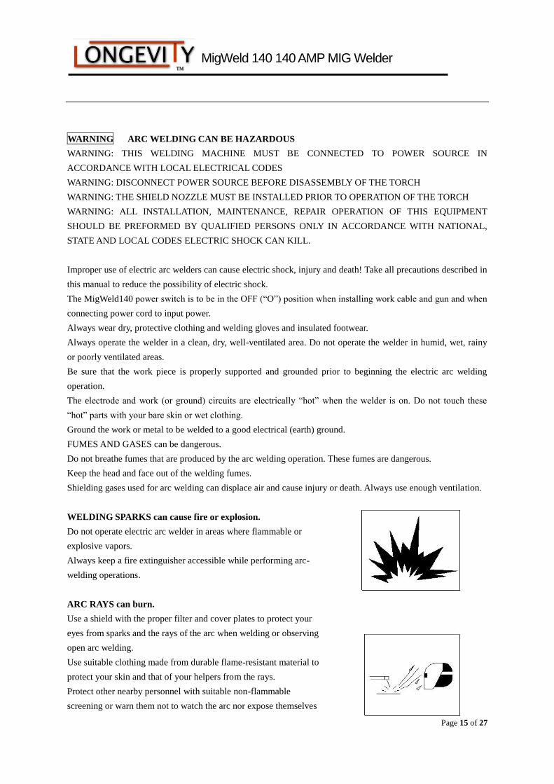
WELDING SPARKS can cause fire or explosion.
Do not operate electric arc welder in areas where flammable or
explosive vapors.
Always keep a fire extinguisher accessible while performing arc-
welding operations.
ARC RAYS can burn.
Use a shield with the proper filter and cover plates to protect your
eyes from sparks and the rays of the arc when welding or observing
open arc welding.
Use suitable clothing made from durable flame-resistant material to
protect your skin and that of your helpers from the rays.
Protect other nearby personnel with suitable non-flammable
screening or warn them not to watch the arc nor expose themselves
MigWeld 140 140 AMP MIG Welder
Page 16 of 27
to the arc rays or to hot spatter or metal.
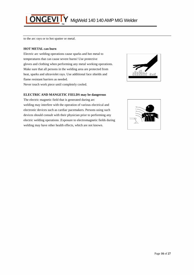
HOT METAL can burn
Electric arc welding operations cause sparks and hot metal to
temperatures that can cause severe burns! Use protective
gloves and clothing when performing any metal working operations.
Make sure that all persons in the welding area are protected from
heat, sparks and ultraviolet rays. Use additional face shields and
flame resistant barriers as needed.
Never touch work piece until completely cooled.
ELECTRIC AND MANGETIC FIELDS may be dangerous
The electric magnetic field that is generated during arc
welding may interfere with the operation of various electrical and
electronic devices such as cardiac pacemakers. Persons using such
devices should consult with their physician prior to performing any
electric welding operations .Exposure to electromagnetic fields during
welding may have other health effects, which are not known.
MigWeld 140 140 AMP MIG Welder
Page 17 of 27
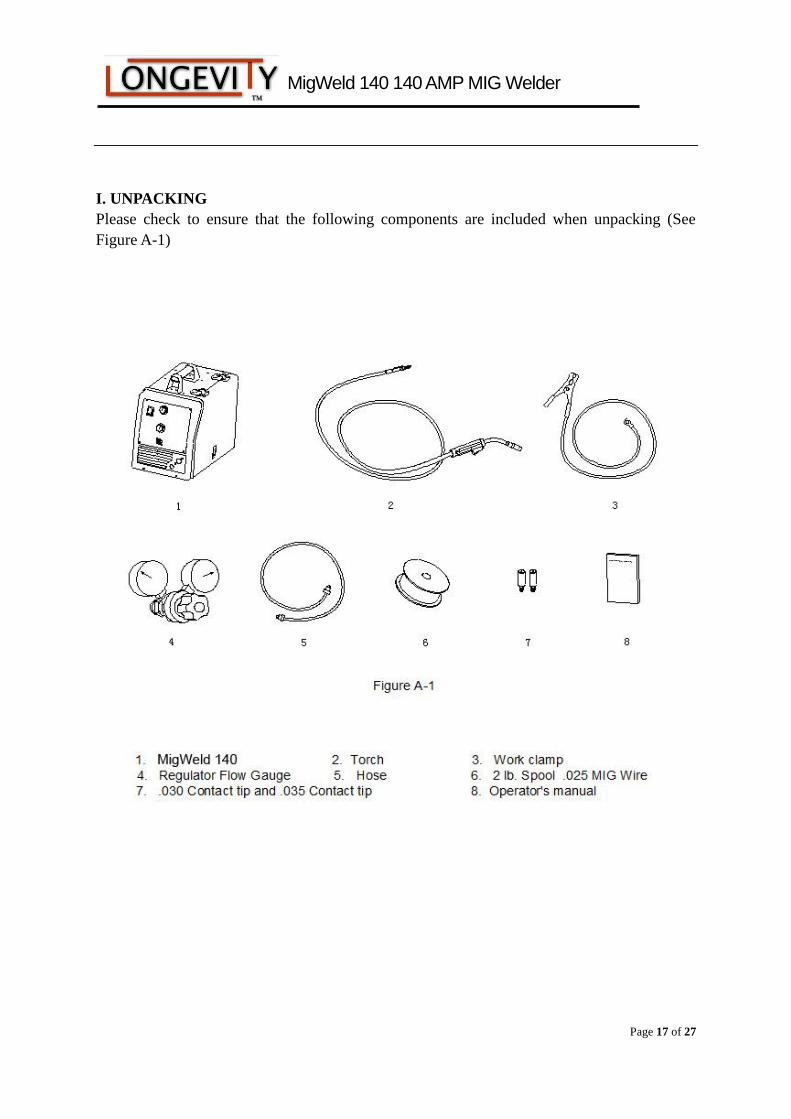
I. UNPACKING
Please check to ensure that the following components are included when unpacking (See
Figure A-1)
MigWeld 140 140 AMP MIG Welder
Page 18 of 27
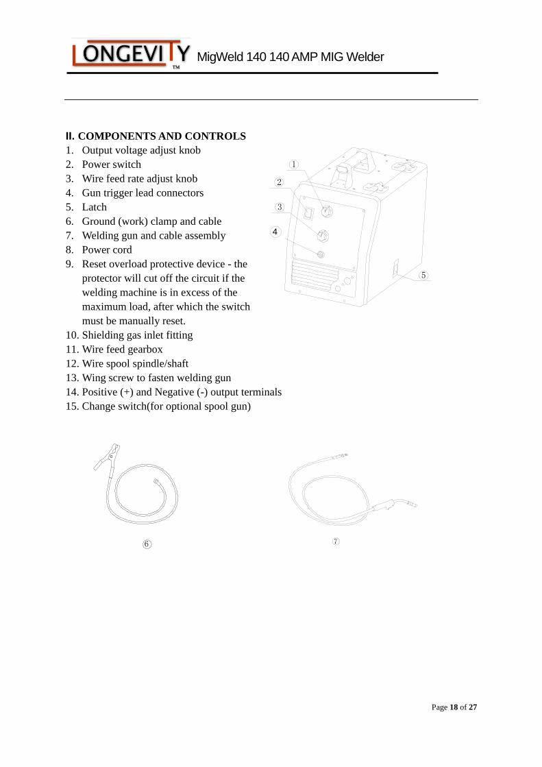
II. COMPONENTS AND CONTROLS
1. Output voltage adjust knob
2. Power switch
3. Wire feed rate adjust knob
4. Gun trigger lead connectors
5. Latch
6. Ground (work) clamp and cable
7. Welding gun and cable assembly
8. Power cord
9. Reset overload protective device - the
protector will cut off the circuit if the
welding machine is in excess of the
maximum load, after which the switch
must be manually reset.
10. Shielding gas inlet fitting
11. Wire feed gearbox
12. Wire spool spindle/shaft
13. Wing screw to fasten welding gun
14. Positive (+) and Negative (-) output terminals
15. Change switch(for optional spool gun)
6
4
2
3
1
5
7
MigWeld 140 140 AMP MIG Welder
Page 19 of 27
10
9
8
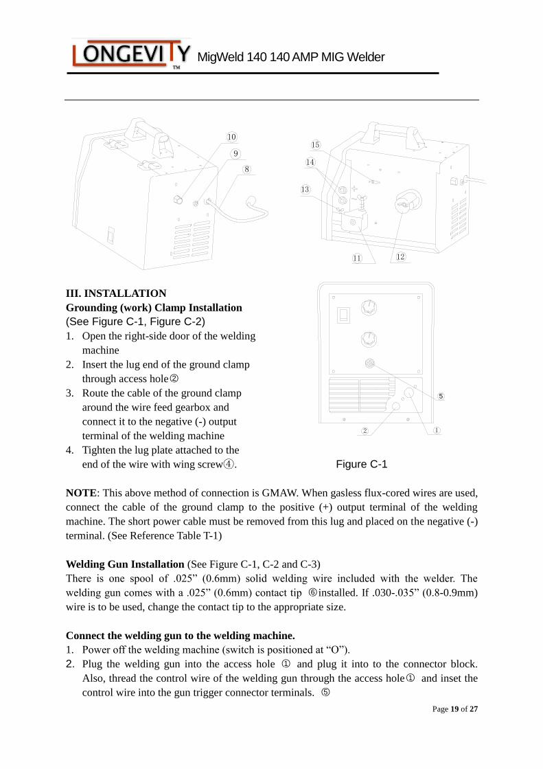
III. INSTALLATION
Grounding (work) Clamp Installation
(See Figure C-1, Figure C-2)
1. Open the right-side door of the welding
machine
2. Insert the lug end of the ground clamp
through access hole○2
3. Route the cable of the ground clamp
around the wire feed gearbox and
connect it to the negative (-) output
terminal of the welding machine
4. Tighten the lug plate attached to the
end of the wire with wing screw④. Figure C-1
NOTE: This above method of connection is GMAW. When gasless flux-cored wires are used,
connect the cable of the ground clamp to the positive (+) output terminal of the welding
machine. The short power cable must be removed from this lug and placed on the negative (-)
terminal. (See Reference Table T-1)
Welding Gun Installation (See Figure C-1, C-2 and C-3)
There is one spool of .025” (0.6mm) solid welding wire included with the welder. The
welding gun comes with a .025” (0.6mm) contact tip ○6 installed. If .030-.035” (0.8-0.9mm)
wire is to be used, change the contact tip to the appropriate size.
Connect the welding gun to the welding machine.
1. Power off the welding machine (switch is positioned at “O”).
2. Plug the welding gun into the access hole ○1 and plug it into to the connector block.
Also, thread the control wire of the welding gun through the access hole○1 and inset the
control wire into the gun trigger connector terminals. ○5
15
1211
13
14
5
2 1
MigWeld 140 140 AMP MIG Welder
Page 20 of 27
6
Figure C-3
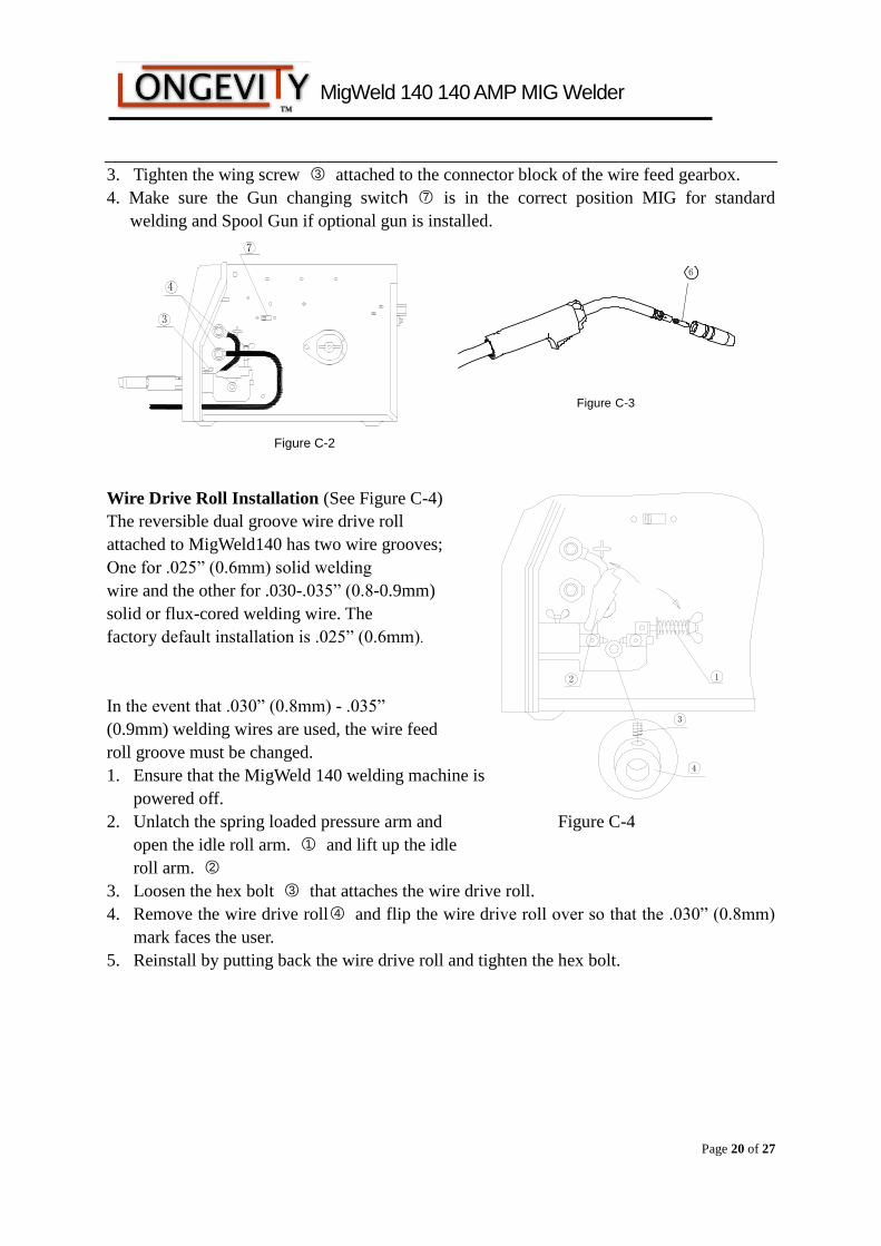
3. Tighten the wing screw ○3 attached to the connector block of the wire feed gearbox.
4. Make sure the Gun changing switch ○7 is in the correct position MIG for standard
welding and Spool Gun if optional gun is installed.
Wire Drive Roll Installation (See Figure C-4)
The reversible dual groove wire drive roll
attached to MigWeld140 has two wire grooves;
One for .025” (0.6mm) solid welding
wire and the other for .030-.035” (0.8-0.9mm)
solid or flux-cored welding wire. The
factory default installation is .025” (0.6mm).
In the event that .030” (0.8mm) - .035”
(0.9mm) welding wires are used, the wire feed
roll groove must be changed.
1. Ensure that the MigWeld 140 welding machine is
powered off.
2. Unlatch the spring loaded pressure arm and Figure C-4
open the idle roll arm. ○1 and lift up the idle
roll arm. ○2
3. Loosen the hex bolt ○3 that attaches the wire drive roll.
4. Remove the wire drive roll○4 and flip the wire drive roll over so that the .030” (0.8mm)
mark faces the user.
5. Reinstall by putting back the wire drive roll and tighten the hex bolt.
4
3
12
7
Figure C-2
3
4
MigWeld 140 140 AMP MIG Welder
Page 21 of 27
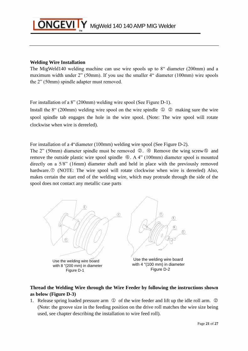
Welding Wire Installation
The MigWeld140 welding machine can use wire spools up to 8“ diameter (200mm) and a
maximum width under 2” (50mm). If you use the smaller 4“ diameter (100mm) wire spools
the 2” (50mm) spindle adapter must removed.
For installation of a 8” (200mm) welding wire spool (See Figure D-1).
Install the 8“ (200mm) welding wire spool on the wire spindle ○1 ○2 making sure the wire
spool spindle tab engages the hole in the wire spool. (Note: The wire spool will rotate
clockwise when wire is dereeled).
For installation of a 4“diameter (100mm) welding wire spool (See Figure D-2).
The 2” (50mm) diameter spindle must be removed ○2 . ○4 Remove the wing screw○5 and
remove the outside plastic wire spool spindle ○6 . A 4” (100mm) diameter spool is mounted
directly on a 5/8” (16mm) diameter shaft and held in place with the previously removed
hardware.○7 (NOTE: The wire spool will rotate clockwise when wire is dereeled) Also,
makes certain the start end of the welding wire, which may protrude through the side of the
spool does not contact any metallic case parts
Use the welding wire board
with 8 "(200 mm) in diameter
Figure D-1
2
1
3
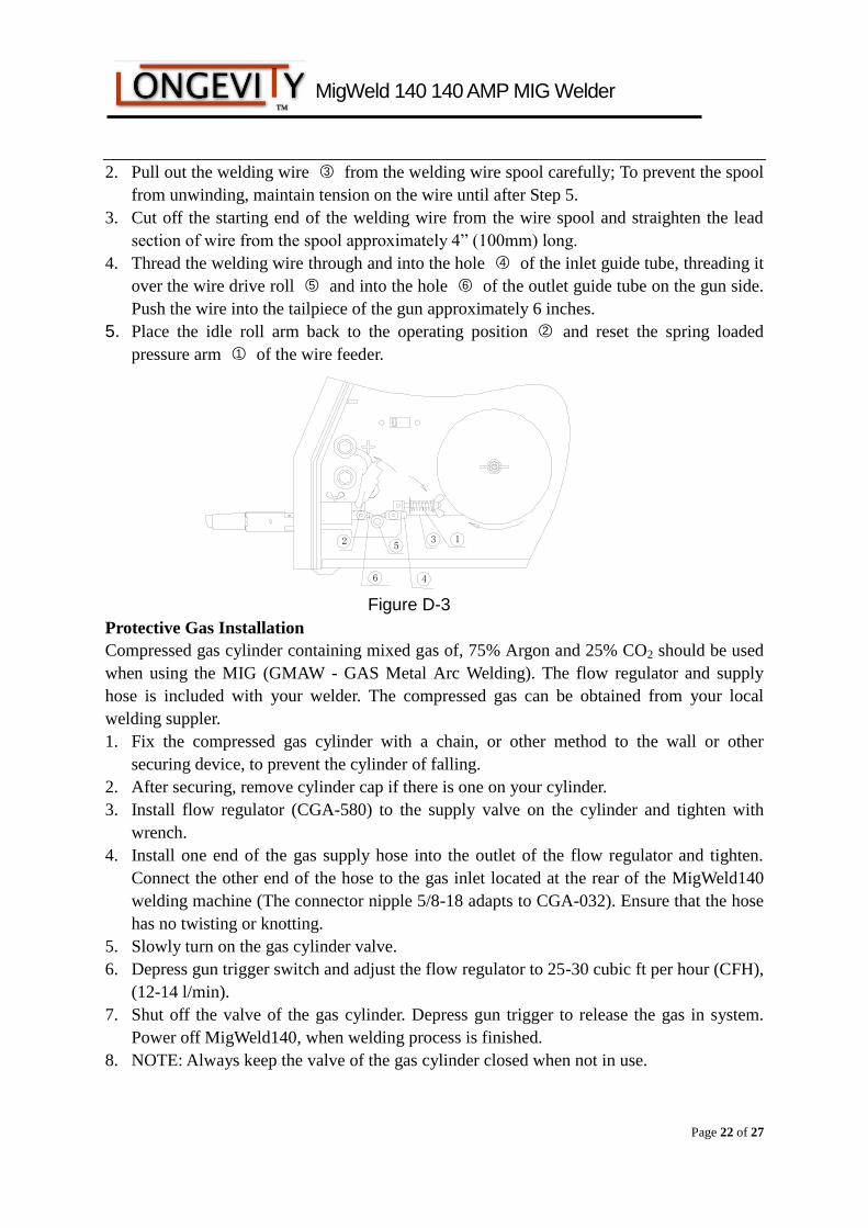
Thread the Welding Wire through the Wire Feeder by following the instructions shown
as below (Figure D-3)
1. Release spring loaded pressure arm ○1 of the wire feeder and lift up the idle roll arm. ○2
(Note: the groove size in the feeding position on the drive roll matches the wire size being
used, see chapter describing the installation to wire feed roll).
Use the welding wire board
with 4 "(100 mm) in diameter
Figure D-2
4
7
6
5
MigWeld 140 140 AMP MIG Welder
Page 22 of 27
2. Pull out the welding wire ○3 from the welding wire spool carefully; To prevent the spool
from unwinding, maintain tension on the wire until after Step 5.
3. Cut off the starting end of the welding wire from the wire spool and straighten the lead
section of wire from the spool approximately 4” (100mm) long.
4. Thread the welding wire through and into the hole ○4 of the inlet guide tube, threading it
over the wire drive roll ○5 and into the hole ○6 of the outlet guide tube on the gun side.
Push the wire into the tailpiece of the gun approximately 6 inches.
5. Place the idle roll arm back to the operating position ○2 and reset the spring loaded
pressure arm ○1 of the wire feeder.
Figure D-3
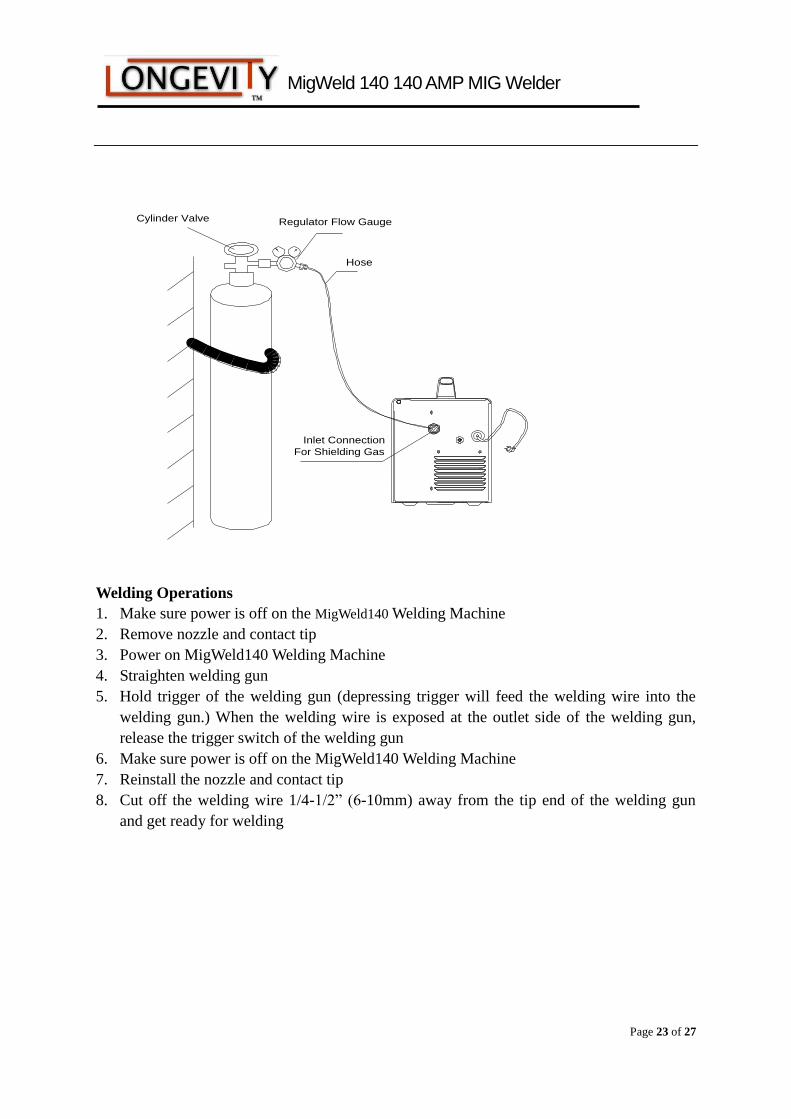
Protective Gas Installation
Compressed gas cylinder containing mixed gas of, 75% Argon and 25% CO2 should be used
when using the MIG (GMAW - GAS Metal Arc Welding). The flow regulator and supply
hose is included with your welder. The compressed gas can be obtained from your local
welding suppler.
1. Fix the compressed gas cylinder with a chain, or other method to the wall or other
securing device, to prevent the cylinder of falling.
2. After securing, remove cylinder cap if there is one on your cylinder.
3. Install flow regulator (CGA-580) to the supply valve on the cylinder and tighten with
wrench.
4. Install one end of the gas supply hose into the outlet of the flow regulator and tighten.
Connect the other end of the hose to the gas inlet located at the rear of the MigWeld140
welding machine (The connector nipple 5/8-18 adapts to CGA-032). Ensure that the hose
has no twisting or knotting.
5. Slowly turn on the gas cylinder valve.
6. Depress gun trigger switch and adjust the flow regulator to 25-30 cubic ft per hour (CFH),
(12-14 l/min).
7. Shut off the valve of the gas cylinder. Depress gun trigger to release the gas in system.
Power off MigWeld140, when welding process is finished.
8. NOTE: Always keep the valve of the gas cylinder closed when not in use.
5
6 4
32 1
MigWeld 140 140 AMP MIG Welder
Page 23 of 27
Hose
Regulator Flow GaugeCylinder Valve
Inlet Connection
For Shielding Gas
Welding Operations
1. Make sure power is off on the MigWeld140 Welding Machine
2. Remove nozzle and contact tip
3. Power on MigWeld140 Welding Machine
4. Straighten welding gun
5. Hold trigger of the welding gun (depressing trigger will feed the welding wire into the
welding gun.) When the welding wire is exposed at the outlet side of the welding gun,
release the trigger switch of the welding gun
6. Make sure power is off on the MigWeld140 Welding Machine
7. Reinstall the nozzle and contact tip
8. Cut off the welding wire 1/4-1/2” (6-10mm) away from the tip end of the welding gun
and get ready for welding
MigWeld 140 140 AMP MIG Welder
Page 24 of 27
Welding Process
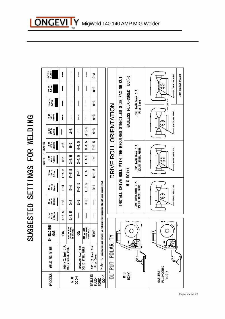
1. Please refer to the welding manual when selecting welding wires and protective gases
based on the metal thickness.
2. Please refer to “Welding Control Guide” that is located inside the welding machine door
for the output voltage and wire feed rates.
3. Inspect output polarity according to the welding wire being used and ensure whether or
not shielding gases are needed.
4. Connect the ground (work) clamp to the piece(s) to be welded; there should be a good
connection for the ground (work) clamp to the piece(s).
5. The welding gun should have free movement in the area of the piece(s) to be welded.
6. Power on the MigWeld140 Welding Machine
7. Pull down welding protective helmet, press the trigger of the welding gun and begin to
weld. Keep the contact tip of the welding gun at around 3/8” to 1/2” (10-13mm) away
from piece(s) to be welded.
8. Release trigger of the welding gun and the welding is stopped.
9. After welding, turn off valve of the compressed gas cylinder (if gas is used) and then
press trigger of the welding gun to release compressed gas in system. Finally, power off
the MigWeld140 Welding Machine.
Optional Spool Gun - Contact your local LONGEVITY dealer for correct Spool Gun
part number.
Your MigWeld140 has a factory installed option to allow you to install and operate a hand
held spool gun. This will allow you to do welding of both Aluminum and Steel. To install the
spool gun you must first power down the welder, remove the standard MIG gun and install
the Spool Gun using the same installation process as described on page 9. You must move
the Change Switch (7) from MIG to Spool Gun. This will disable the drive system of the
welder and enable the Spool Gun’s drive system. Reference the owner’s manual of the Spool
Gun for operating procedures and instructions of the Spool Gun.
MigWeld 140 140 AMP MIG Welder
Page 25 of 27
MigWeld 140 140 AMP MIG Welder
Page 26 of 27
V.Overload Protection
Overload protection for power supply to welding
The MigWeld140 Welding Machine is equipped with a circuit breaker and a thermostat,
which protects the machine from damage if maximum output is exceeded. The circuit breaker
button will extend out when tripped. The circuit breaker must be manually reset. Wait for
several minutes while the welding machine cools down and reset the circuit breaker button.
Thermal Protection
The MigWeld140 has a rated output duty cycle of 20%. If the duty cycle is exceeded, a
thermal protector will shut off the output until the machine cools to a reasonable operating
temperature. This is an automatic function and does not require user intervention. The fan
continues to run during cooling.
Overload Protection to Wire feeder
The MigWeld140 model has two automatic circuits to protect the motor of the wire drive.

MigWeld 140 140 AMP MIG Welder
Page 27 of 27
LONGEVITY® Global, Inc. thanks you for your purchase and the opportunity to be able to serve you.
If, after reviewing this manual, you have any problems in setting up or operating your machine,
contact us at [email protected].
LONGEVITY® Global, Inc.
Toll-Free 1-877-LONG-INC / 1-877-566-4462
Website: www.longevity-inc.com
Sales: [email protected]
Customer Service: [email protected]
Dealers: [email protected]
Please join our welding forums to share welding tips and tricks, to receive useful information from
customers who also use our products, and to be a part of the LONGEVITY® welding community at
www.freeweldingforum.com
For the coolest LONGEVITY sponsored race teams plus a complete racing forum that covers
everything from Drag Racing to RC Car Racing, please check out www.longevity-racing.com!
Enjoy your new welding machine from LONGEVITY! Thanks again!