Embed Size (px)
Citation preview
REITER GmbH + Co. KG Oberflächentechnik Phone: +49 (0) 71 95 / 185 - 0Berglenstraße 23 - 25 Fax: +49 (0) 71 95 / 185 - 30D-71364 Winnenden Internet: www.reiter-oft.de
Operating ManualElectrostatic High Rotation SystemCenter Bell 2012
Product No.: S-CB2012-GB (Original)Issue: 01/18 - 5
S-CB2012gbDB 01/18 - 5
Contents of the Operating Manual
Chapter 1 General
Chapter 2 Safety Regulations
Chapter 3 Technical Data
Chapter 4 Transport (not assigned)
Chapter 5 Function Description
Chapter 6 Installation (not assigned)
Chapter 7 Commissioning and Operation (not assigned)
Chapter 8 Maintenance
Chapter 9 Spare Parts
Chapter 10 Appendix (not assigned)
S-CB2012gb01 01/18 - 5 Page 1 of 2
1 General
Table of Contents
1.1 Introduction ........................................................................................................................11.2 Scope of application – Correct use according to regulations .............................................11.2.1 Improber use .....................................................................................................................21.3 Guarantee .........................................................................................................................21.4 Copyright............................................................................................................................2
1.1 IntroductionThis operating manual contains information for installation, maintenance and care of the electro-static high rotation system Center Bell 2012. The values and procedures given herein are to be regarded as standard and may vary due to different conditions from standard.
Since each installation is designed differently, the electrostatic high rotation system Center Bell 2012 may only be put into operation by authorized personnel of company REITER GmbH + Co. KG Oberflächentechnik.
To better understand this product and to achieve an optimal, long time trouble free operation, please read this manual carefully. The specified testing and troubleshooting should be performed before a technician is required.
We reserve the right, to develop and improve the electrostatic high rotation system Center Bell 2012.
1.2 Scope of application – Correct use according to regulationsRisk of injury and damage!This devices can be harmful if not operated according to the instruc-tions of this manual.
The electrostatic high rotation system Center Bell 2012, is designed and built for electrostatic paint-ing with flammable and non-flammable, liquid coating materials in a stationary spray installation on robots, automated machines (reciprocator) and tripods. If water-dilutable coating materials must be processed the relevant rules to be considered. It is recommended to consult in case if doubt the REITER GmbH + Co. KG Oberflächentechnik
The electrostatic high rotation system Center Bell 2012 may be used in explosive atmospheres only when an explosive atmosphere is generated solely by the spray cloud of the processed coat-ing material itself.
It is approved for use in hazardous areas Zone 2.Any other use is considered improper. The manufacturer is not liable for any resulting damage. The risk is on the operator.
Attention!
S-CB2012gb01 01/18 - 5 Page 2 of 2
1 General
Intended use also includes compliance with the prescribed installation, dismantling, commissioning, operation and maintenance requirements from REITER GmbH + Co. KG Oberflächentechnik.
Note:In the processing of highly corrosive or highly abrasive materials can be expected with an in-creased need for spare parts. The suitability is resolvable on the list of materials with the material supplier.
1.2.1 Improber use Improper use occurs when:
• other media are passed through the spray system as are provided in the operating instructions
• other operating conditions as applied in the operating instructions are provided.
• during operation, installation and maintenance, safety find no attention.
• unauthorized modifications or changes to the Center Bell 2012 to be made, which affect the safety or functionality.
1.3 Guarantee This manual must be read carefully as REITER GmbH + Co. KG Oberflächentechnik for any dam-age or malfunctions resulting from failure to comply with this manual, assumes no liability.
During the warranty period repairs and/or modifications shall only be carried out by mechanics and/or technicians of REITER GmbH + Co. KG Oberfächentechnik or with our written consent.
The system is designed for the intended use described in chapter 1.2 of the according product specific operation manuals. Any other use is noted as „unintended use“ and voids the warranty immediately. All damages and/or faults, which may occur from an unintended use, are the sole re-sponsibility of the operator.
1.4 CopyrightThe copyright for this operation manual is retained by REITER GmbH + Co. KG Oberflächentech-nik. This operation manual is intended for personnel involved in installation, operation and supervi-sion. All in this operation manual included regulations, technical drawings, pictures, and text shall not be copied, distributed, used for commercial purpose, or given to others, either in full or in part.
REITER GmbH + Co. KG Oberflächentechnik Phone: +49 (0) 71 95 / 185 - 0Berglenstraße 23 - 25 Fax: +49 (0) 71 95 / 185 - 30D-71364 Winnenden Email: [email protected]
S-CB2012gb02 01/18 - 5 Page 1 of 5
2 Safety Regulations
Achtung!Attention!
!
Table of Contents
2.1 Explanation of symbols and special directions ..................................................................12.1.1 Symbol of working safety ...................................................................................................12.1.2 Directions for “Attention“ ....................................................................................................12.1.3 Explosion protection notice ................................................................................................22.2 Safety instructions..............................................................................................................22.2.1 Scope .................................................................................................................................22.2.2 Automatic electrostatic painting system .............................................................................22.2.2.1 Technical ventilation ...........................................................................................................32.2.3 General requirements for safe operation ...........................................................................32.2.4 Instructions.........................................................................................................................32.2.5 Use of electrostatic application equipment in potentially explosive atmospheres ......................................................................................................................32.2.6 Workplaces ........................................................................................................................42.2.7 Cleaning .............................................................................................................................42.2.8 Preconditions for entering the paint booth .........................................................................42.2.9 Personal protective equipment ..........................................................................................42.2.10 Work with risk of ignition ....................................................................................................52.3 Explosion protective document ..........................................................................................52.3.1 Basis ..................................................................................................................................52.4 Examinations .....................................................................................................................5
2.1 Explanation of symbols and special directions
2.1.1 Symbol of working safetyThis symbol found on all work safety notes in these instructions, if ignored, may cause hazards. The instructions must be particularly observed by the users of the machine. Inform other users of potential hazards that can occur when using the machine. Besides the recom-mendations in this OM to the general safety and accident prevention and safety regulations.
2.1.2 Directions for “Attention“This warning is shown at points where special attention needs to be given in order that guidelines, regulations, special directions, and proper work procedures are observed and to prevent damage or de-struction of the machine and/or other parts of the plant.
S-CB2012gb02 01/18 - 5 Page 2 of 5
2 Safety Regulations
2.1.3 Explosion protection noticeThis symbol in the operating manual are important explosion protec-tion notices. In general, the observance of the information is a pre-requisite for trouble-free operation and fulfillment of warranty claims. Therefore, read the operating manual before you start operating the spray system.
2.2 Safety instructions
2.2.1 ScopeThe electrostatic high rotation system Center Bell 2012, is designed and constructed for use in a stationary electrostatic spraying installation of flammable and non-flammable, liquid coating materi-als.
Applied standards:
• DIN EN 12215 – Coating equipment – Spray booths for application of organic liquid coating materials – Safety requirements
• DIN EN 50176 – Stationary electrostatic application equipment for ignitable liquid coating ma-terial – Safety requirements
• DIN EN 13463-1 – Non-electrical equipment for use in potentially explosive atmospheres - Part 1: Basic method and requirements
• DIN EN 13463-5 – Non-electrical equipment intended for use in potentially explosive atmos-pheres - Part 5: Protection by constructional safety ‚c‘
• DIN EN ISO 12100 – Safety of machinery - General principles for design - Risk assessment and risk reduction
The EN 50176 applies to the scope of application of this device.
The standard covers the constructional requirements for the safe operation of the device as well as the electrical installation including the technical ventilation.
The requirements for the construction of the painting booth must also be considered. The require-ments are defined in the standard EN 12215. This applies, in particular, for the establishing of the areas with potentially explosive atmospheres. It is only allowed to use the device in areas accord-ing to paragraph 5.4 of EN 50176.
When using the device in painting plants of the type D-L or higher according to EN 50176, only closed painting booths with door locking systems may be used.
2.2.2 Automatic electrostatic painting systemThe painting system fulfills the requirements of the EN 50176 – Stationary electrostatic application equipment for ignitable liquid coating material – Safety requirements.
This manual covers only the common dangers for electrostatic high rotation applications if it is worked under the standards of the REITER GmbH + Co. KG Oberflächentechnik.This electrostatic high rotation application system is classified as a group II, category 3 device ac-cording to the directive 2014/34/EC. Equipment in this category is intended to use in areas in which explosive atmospheres caused by gases, vapors, mist, or air/dust mixtures are unlikely to occur or, if they do so only infrequently and for a short period only.
S-CB2012gb02 01/18 - 5 Page 3 of 5
2 Safety Regulations
2.2.2.1 Technical ventilation
According to EN 50176 it is only allowed to use electrostatic high rotation systems in spray booth which are equipped with a technical ventilation system. The high voltage supply system must be locked with the technical ventilation system and the paint booth door. It must be not possible to turn on the high voltage if the paint booth doors are open or if the technical ventilation is shut down.
2.2.3 General requirements for safe operation • In order to guarantee a safe operation of the application system the operating company has to
provide an operating instruction according to the operation manual. This operating procedure must be provided in an appropriate language and at an appropriate location.
• The operating instruction must include the note that electrostatic painting equipment must only be operated by trained personnel.
• A warning sign which is showing the most important working methods must be place nearby the painting booth. The warning sign language must be understood by the working personnel. (see EN 50176)
• The first start up is only allowed if an examination according to EN 50167 was successfully carried out. See chapter 2.4 of this operation manual.
2.2.4 InstructionsIt is important to ensure that the personnel which is working with the electrostatic application equip-ment is instructed in all risks according to the application system. The staff instruction should be re-peated on an annual basis; all people participating in such training should confirm their participation by signature.
2.2.5 Use of electrostatic application equipment in potentially explosive atmospheres
It is only allowed to use electrostatic application equipment under consideration of protective meas-ures against typical dangers (see EN 50176:2009 for further information). It should also be ensured that there are protective measures to prevent dangerous body currents.
• No work on parts under power
• Clear voltage
• Suitable working cloths
• Secure against being switched on again
• Validate that power is off
• Ground the system
• Work on the electrostatic system only with a working permit
S-CB2012gb02 01/18 - 5 Page 4 of 5
2 Safety Regulations
2.2.6 Workplaces • Avoid all ignition sources. For example nor flames, sparks or smoking.
• Keep the electrostatic equipment such as the painting booth free from all kinds of deposits.
• Any kinds of internal coating which can cause potentially explosive atmospheres inside the work piece are prohibited without additional safety measures.
• Access doors must be closed and locked during the painting operation.
2.2.7 Cleaning • Make sure that the high voltage system is secured against unintentional reactivation before
performing any kind of cleaning or other manual work on the system.
• Keep the electrostatic equipment such as the painting booth free from all kinds of deposits.
• The work piece carriers must be cleaned regularly
• The technical ventilation must be working during the cleaning work
• It is only allowed to use electrically conductive containers for the rinsing agent. The containers must be grounded.
• It is only allowed to use solvents with a flashpoint which is at least 5K higher than the ambient temperature. If possible use nonflammable solvents.
• Make sure that the discharging energy of the painting system is below 0,24 mJ before starting cleaning work with flammable solvents. Ground the system before cleaning.
2.2.8 Preconditions for entering the paint booth • The solvent concentration inside the paint booth must be at a non-harmful level before the
paint booth can be entered.
• Make sure that the floor of the paint booth is electrically conductive.
• Ensure that nobody is inside the paint booth during the application process. Access doors must be locked.
• Make sure that all high voltage parts are discharged to a discharge energy of <350 mJ before they can be reached. The discharge time must be set after the local conditions.
• Make sure that the discharging energy of the painting system is below 0,24 mJ before starting cleaning work with flammable solvents. Ground the system before cleaning.
2.2.9 Personal protective equipment • Make sure that persons in the areas of the antistatic floor or working on the electrostatic ap-
plication system are wearing antistatic shoes. The shoes must be according to EN ISO 20344. The insulation resistance must not be higher than 100 MΩ.
• Protective clothing and protective gloves must accord to EN 1149-5. The insulation resistance must not be higher than 100 MΩ.
S-CB2012gb02 01/18 - 5 Page 5 of 5
2 Safety Regulations
2.2.10 Work with risk of ignition • It is not allowed to carry out any work with ignition risk in potentially explosive atmospheres.
Special protective measures must been taken before working in potentially explosive atmos-pheres e.g. remove ignitable coating material or solvents, working technical ventilation, clean the application system
• Make sure that no work with ignition risk is performed near openings of rooms with potentially explosive atmospheres.
2.3 Explosion protective document
2.3.1 BasisThe explosion protective document must be created within the risk assessment according to § 6, (4) GefStoffV. The essential elements are:
• can dangerous quantities of hazardous materials can cause potentially explosive atmospheres
• are ignition sources existing which can cause explosions
• can explosions cause harmful effects on the health and safety of employees
It must follow from the explosion protection document in accordance with § 6 (9) GefStoffV that:
• the explosion hazard has been identified and assessed
• a explosion protection concept was created
• if zone with a risk of explosion were defined. Which areas are equipped with protective meas-ure according to § 11 GeffStoffV
• how the safety is guaranteed between several companies working together. Which test have to be made according to the GefStoffV and the BetrSichV
2.4 Examinations • A stationary electrostatic application system has to be examined according to the safe working
condition by a qualified person before the first start up. The examination must be performed separately for every application system.
• Type, scope and frequency of the examination must be set by the operating company regard-ing the local conditions. The examination notes should be recorded.
• The electrostatic application system has to be examined according to the safe working condi-tion by a qualified person every year. The examination must be recorded.
• It must be ensure that there is a sufficient amount of fire extinguishers at the painting system. The inspection periods of the fire extinguishers must be fulfilled. The working personnel must be trained in the operation of the fire extinguishers.
S-CB2012gb03 01/18 - 5 Page 1 of 4
3 Technical Data
Table of Contents
3.1 Technical data ....................................................................................................................13.2 Permitted device combinations ..........................................................................................23.3 Dimensions Center Bell 2012 ............................................................................................33.3.1 Versionforreciprocatororfixedsupport(1).......................................................................33.3.2 Versionforrobots,typehollowwrist(2) .............................................................................4
3.1 Technical dataSeries: Spraying system Center Bell 2012 Nominalvoltage: max.80kV
Outputcurrent: 350µA
Weight: approx.7,5kgincl.flange (withouthosepackageandwithoutholders)
Compressedairsupply(onsite): Condensateandoilfreequalitystandard: class 3-MF 0,1 mg/m3 technical oil free min.6,0bardynamic,max.8bar Compressedairturbine: pressurevariesaccordingtothepreselectedsetspeed –max.50.000rpm
Shapingair: min.0,4bar-max.6bar
Blockingair: min.1,5bar(dependingonproject)
Materialvalvescontrolair: min.5bardynamic-max.8bar
Speed: min.10.000rpm-max.50.000rpm
Airconsumption: max.1500NL/minat6bar (totalforturbine,shapingairandblockingair)
Materialpressure: max.permitted10bar
S-CB2012gb03 01/18 - 5 Page 2 of 4
3 Technical Data
Materialpaintflow: Thematerialpaintflowisdependentontheviscosityofthe mediumtobeprocessed,thematerialaccordingtoatomizer bellused.Togetagoodatomization,thematerialpaintflow shouldnotbehigherthan600ml/min.
Thematerialpaintflowof600ml/minisanaverage. Deviationsbeloworabovearepossibleinindividualcases (materialproperties).
Liquids,whichcontainchlorinatedhydrocarbonsorzincdustaswellaszincchromatepaintsareexcluded.ItisrecommendedtocheckwiththeREITERGmbH+Co.KGOberflächentechnikintheindividualcase.
3.2 Permitted device combinationsTheoperationofthehighrotationatomizerCentreBell2012,isonlypermittedwiththefollowinghigh voltage generators:
• HVgeneratorPAC101
• HVgeneratorGE32P
• HS-GeneratorRHS-310p
• HS-GeneratorRHS-510p
Operation at other than the device listed here, voids any liability.
S-CB2012gb03 01/18 - 5 Page 3 of 4
3 Technical Data
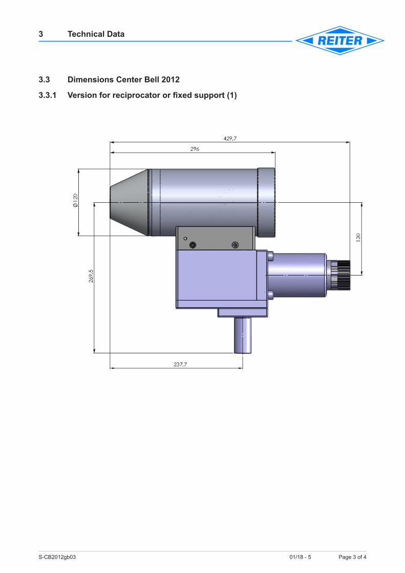
3.3 Dimensions Center Bell 2012
3.3.1 Versionforreciprocatororfixedsupport(1)
S-CB2012gb03 01/18 - 5 Page 4 of 4
3 Technical Data
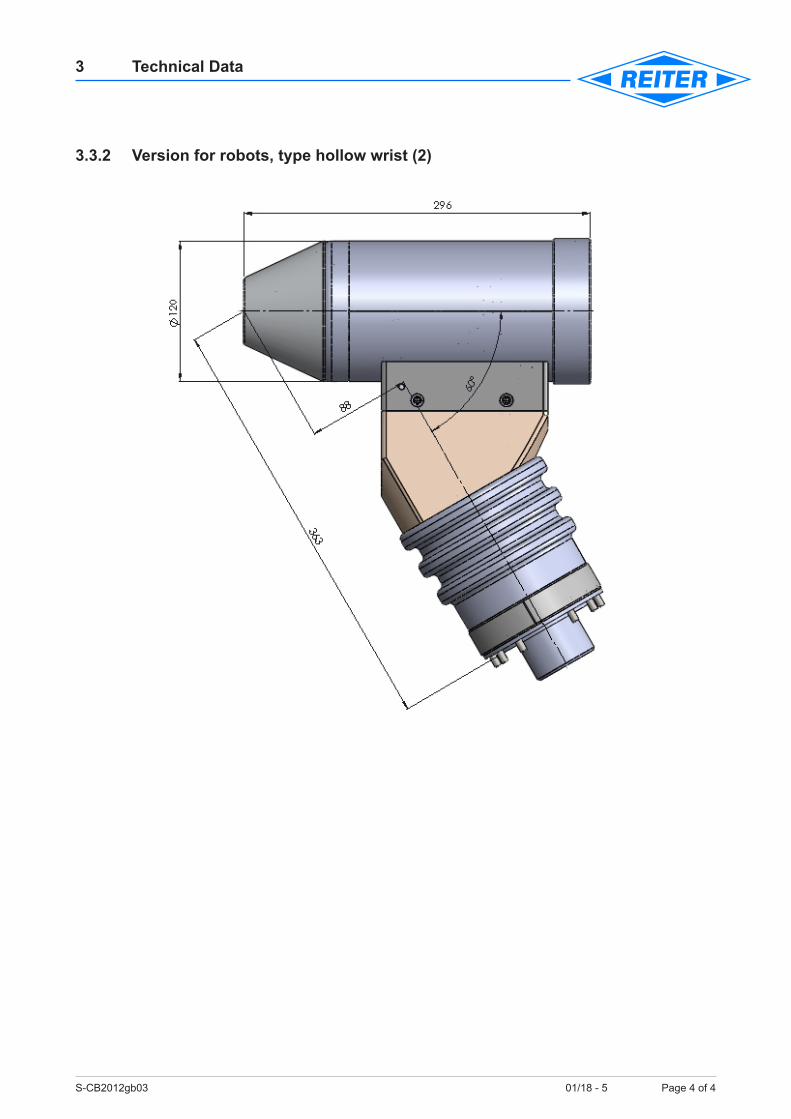
3.3.2 Versionforrobots,typehollowwrist(2)
S-CB2012gb05 01/18 - 5 Page 1 of 10
5 Function Description
Table of Contents
5.1 Technical product description.............................................................................................15.1.1 Automatic spraying system Center Bell 2012 with change unit .........................................15.2 Essential components of the Center Bell 2012 ..................................................................25.2.1 (A) Terminal block and insulating support ..........................................................................35.2.2 (B) Supply lines/Hose package ..........................................................................................45.2.3 (C) Valve unit “G” ...............................................................................................................65.2.3.1 (C) Valve unit “G“ – Control air hoses paint coding ............................................................75.2.4 (D) Compressed air turbine................................................................................................85.2.5 (E) Atomizer .......................................................................................................................95.3 Setting of the individual parameters.................................................................................10
5.1 Technical product description
5.1.1 Automatic spraying system Center Bell 2012 with change unitThe spraying system Center Bell 2012 with direct high tension charging is an air driven high rota-tion system. The bell is rotating at very high speed – max. 50.000 rpm during application. It reaches a very fine pulverization of liquid media, preferably paint. This method is used for the painting of parts made of different materials. The spraying system Center Bell 2012 can be installed on fixed supports or on appropriate move-ment facilities, like robots or reciprocators.
The design/construction is characterized that all functional elements are combined in a module (change unit).
The supply lines (cable package) can be connected to the flange.
The change unit is fixed by index bolts and secured with screws.
The high voltage cable will performed without interruption directly to valve unit.
The replacement of the complete change unit is carried out in ≤ than 3 minutes.
S-CB2012gb05 01/18 - 5 Page 2 of 10
5 Function Description
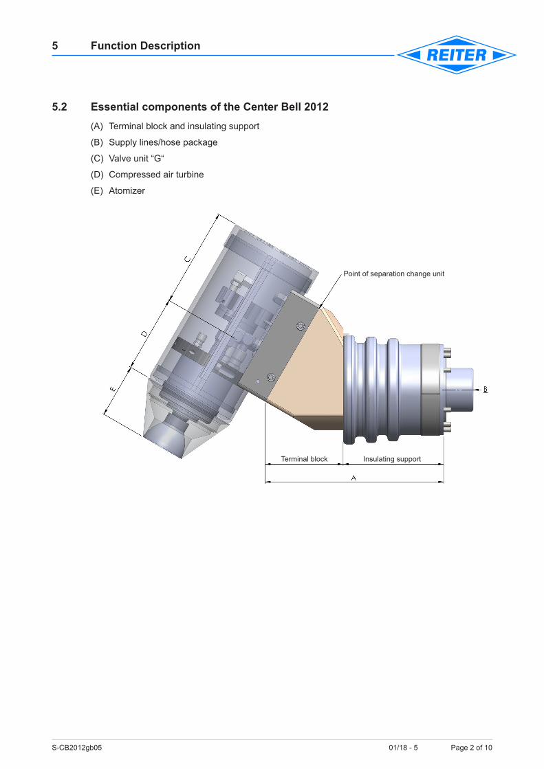
5.2 Essential components of the Center Bell 2012 (A) Terminal block and insulating support
(B) Supply lines/hose package
(C) Valve unit “G“
(D) Compressed air turbine
(E) Atomizer
Point of separation change unit
Terminal block Insulating support
S-CB2012gb05 01/18 - 5 Page 3 of 10
5 Function Description
5.2.1 (A) Terminal block and insulating supportThe terminal block consists basically of a plastic housing with the possible mounting at an insulated support at the reciprocator/fixed support, see chapter 3.2.1 (1) or on a robot type hollow wrist, see chapter 3.2.2 (2)
S-CB2012gb05 01/18 - 5 Page 4 of 10
5 Function Description
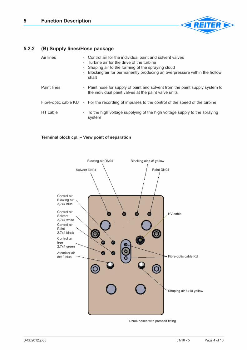
5.2.2 (B) Supply lines/Hose packageAir lines - Control air for the individual paint and solvent valves - Turbine air for the drive of the turbine - Shaping air to the forming of the spraying cloud - Blocking air for permanently producing an overpressure within the hollow shaft
Paint lines - Paint hose for supply of paint and solvent from the paint supply system to the individual paint valves at the paint valve units
Fibre-optic cable KU - For the recording of impulses to the control of the speed of the turbine
HT cable - To the high voltage supplying of the high voltage supply to the spraying system
Terminal block cpl. – View point of separation
Blocking air 4x6 yellow
Paint DN04
HV cable
Shaping air 8x10 yellow
Fibre-optic cable KUAtomizer air8x10 blue
Control air free 2,7x4 green
Control airPaint2,7x4 black
Control airSolvent 2,7x4 white
Control airBlowing air2,7x4 blue
Blowing air DN04
Solvent DN04
DN04 hoses with pressed fitting
S-CB2012gb05 01/18 - 5 Page 5 of 10
5 Function Description
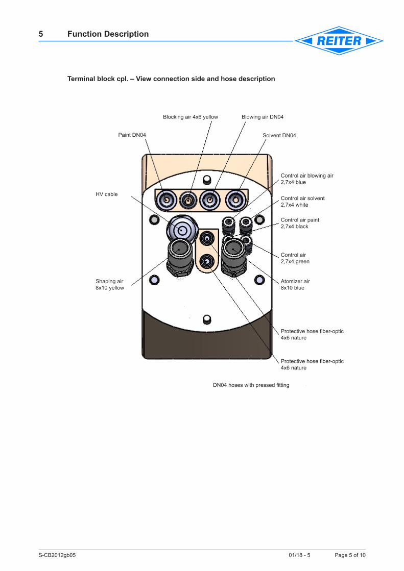
Terminal block cpl. – View connection side and hose description
Protective hose fiber-optic4x6 nature
DN04 hoses with pressed fitting
Atomizer air8x10 blue
Control air 2,7x4 green
Control air paint2,7x4 black
Control air solvent 2,7x4 white
Control air blowing air2,7x4 blue
Protective hose fiber-optic4x6 nature
Shaping air 8x10 yellow
HV cable
Blowing air DN04
Solvent DN04
Blocking air 4x6 yellow
Paint DN04
S-CB2012gb05 01/18 - 5 Page 6 of 10
5 Function Description
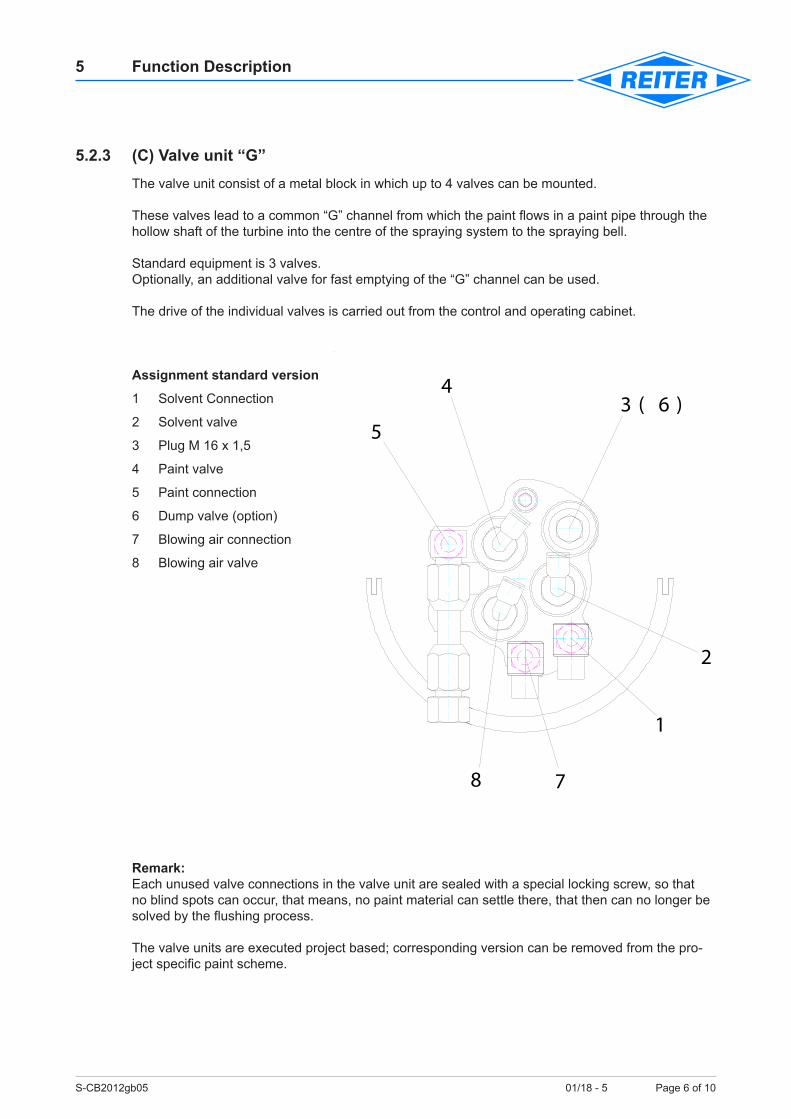
5.2.3 (C) Valve unit “G”The valve unit consist of a metal block in which up to 4 valves can be mounted.
These valves lead to a common “G” channel from which the paint flows in a paint pipe through the hollow shaft of the turbine into the centre of the spraying system to the spraying bell.
Standard equipment is 3 valves.Optionally, an additional valve for fast emptying of the “G” channel can be used.
The drive of the individual valves is carried out from the control and operating cabinet.
Assignment standard version
1 Solvent Connection
2 Solvent valve
3 Plug M 16 x 1,5
4 Paint valve
5 Paint connection
6 Dump valve (option)
7 Blowing air connection
8 Blowing air valve
Remark: Each unused valve connections in the valve unit are sealed with a special locking screw, so that no blind spots can occur, that means, no paint material can settle there, that then can no longer be solved by the flushing process.
The valve units are executed project based; corresponding version can be removed from the pro-ject specific paint scheme.
3 ( 6 )4
5
8 7
1
2
S-CB2012gb05 01/18 - 5 Page 7 of 10
5 Function Description
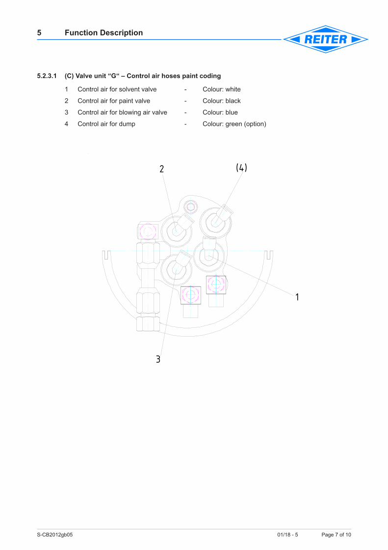
5.2.3.1 (C) Valve unit “G“ – Control air hoses paint coding
1 Control air for solvent valve - Colour: white
2 Control air for paint valve - Colour: black
3 Control air for blowing air valve - Colour: blue
4 Control air for dump - Colour: green (option)
1
(4)
3
2
S-CB2012gb05 01/18 - 5 Page 8 of 10
5 Function Description
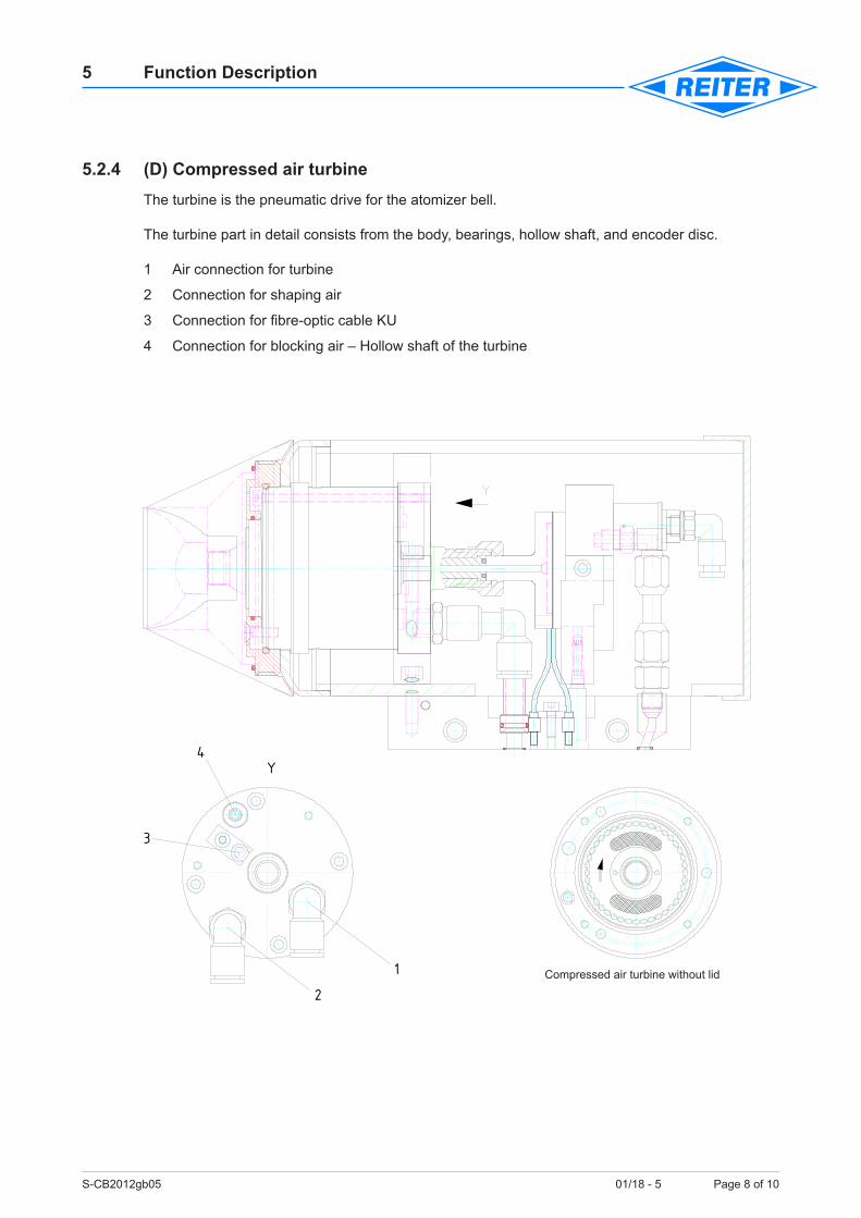
5.2.4 (D) Compressed air turbineThe turbine is the pneumatic drive for the atomizer bell.
The turbine part in detail consists from the body, bearings, hollow shaft, and encoder disc.
1 Air connection for turbine
2 Connection for shaping air
3 Connection for fibre-optic cable KU
4 Connection for blocking air – Hollow shaft of the turbine
Druckluftturbine ohne Deckel
Y
1
4
3
2Compressed air turbine without lid
S-CB2012gb05 01/18 - 5 Page 9 of 10
5 Function Description
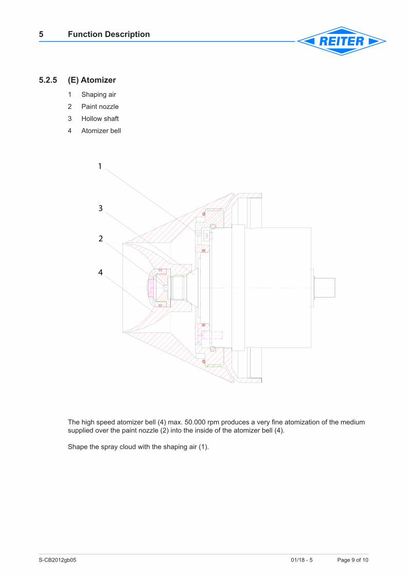
5.2.5 (E) Atomizer 1 Shaping air
2 Paint nozzle
3 Hollow shaft
4 Atomizer bell
The high speed atomizer bell (4) max. 50.000 rpm produces a very fine atomization of the medium supplied over the paint nozzle (2) into the inside of the atomizer bell (4).
Shape the spray cloud with the shaping air (1).
1
3
2
4
S-CB2012gb05 01/18 - 5 Page 10 of 10
5 Function Description
5.3 Setting of the individual parametersThe automatic spraying system is operated by a central control cabinet which is outside the paint booth.
After switching on the control voltage at the central cabinet (electric pneumatic) the automatic spraying system can be activated.
Now, the following parameters can be adjusted at the control cabinet (visualization).
There are:
• High tension
• Turbine – speed
• Shaping air
• Paint quantity
• Solvent pressure manual (pump pressure)
The following parameters can be set manually at the control cabinet
• Blocking air
S-CB2012gb08 01/18 - 5 Page 1 of 35
8 Maintenance
Table of Contents
8.1 General maintenance notes for electrostatic high rotation systems ..................................18.2 Cleaning .............................................................................................................................28.2.1 Intervals of cleaning works.................................................................................................28.2.2 Cleaning of the components ..............................................................................................48.3 Intervals of maintenance works .......................................................................................108.3.1 Daily check (before or after shift start/end) ......................................................................108.3.2 Weekly check ................................................................................................................... 118.3.3 Behaviour during longer operation interruption ................................................................128.3.4 Behaviour in malfunction of the spray system ................................................................128.4 Exchange the change unit Center Bell 2012 ...................................................................138.4.1 Procedure – Exchange the change unit ...........................................................................148.4.2 How to install the change unit ..........................................................................................158.4.3 Overview O-rings in the change unit ................................................................................178.5 Maintenance at the spraying system Center Bell 2012 ...................................................188.5.1 Spray bell – Disassemble/assemble ................................................................................198.5.2 Maintenance instruction for spraying bell Convex ...........................................................218.5.2.1 Mounting device for spray bell Convex (part no. 63135020) – Option .............................238.5.3 Paint nozzles – Disassemble/assemble...........................................................................268.5.4 Change turbine – Disassemble/assemble .......................................................................288.6 Paint valve/Solvent valve – Disassemble/assemble ........................................................298.7 Spraying system complete – Disassemble/assemble ......................................................308.8 Terminal block – Hose package .......................................................................................338.9 Optic cable (Scheme speed measurement).....................................................................34
8.1 General maintenance notes for electrostatic high rotation systemsWhen working at the spraying system personal safety equipment must be worn (e.g. breath protective mask, safety goggles, protective glove).
Before the cleaning of the spraying system or the execution of other work in the spraying area, the high voltage must be switch off.
Residual charges must with the ground rod located in the spray booth, by touching the spray system in the metal area, e.g. grounded at the bell cap.
Edges are sensitive (see page 9)!
Before maintenance and repair work, the system must be flushed and all material and compressed air lines to be depressurized. It must be ensured that the components can not be put into operation dur-ing maintenance and repair work.
!
Attention!
S-CB2012gb08 01/18 - 5 Page 2 of 35
8 Maintenance
Only a cleaning liquid (thinner) of the risk A2 class of may be used for the cleaning of the spraying system with a flash point more than 21°C.
For cleaning the spray system in the processing of so-called water-based paints, use cleaning agent recommended by the paint manufac-turer. Please note, butylglycol residues are conductive. Remark• Do not put components of the spraying system into cleaning liquids for some time. • Do not damage spraying bell.
Damages of the spraying bell lead to imbalance and will destroy the durability of the bearings of the turbine.
8.2 Cleaning
8.2.1 Intervals of cleaning worksAny cleaning should only be performed by through authorized Reiter professionals through training or proper instructions.
Use only plant- or components compatible cleaner. If in doubt, consult the system/application man-ufacturer.
Do not use brushes, thy may lose bristles. Do not use cloths that lint or other auxiliary tools, lose particles. They are not allowed for cleaning.
Cloth or other wetted tools with cleaner are basically wipe off prior to contact with the Centre Bell 2012 unit that no drops of the medium can run into the unit. A spraying or injecting of the atom-izer unit is not allowed. When cleaning with compressed air or with support of compressed air is to make sure that no medium or dirt particles in the drive (turbine) can pass.
A warranty claim by REITER GmbH + Co. KG Oberflächentechnik is excluded by the use of unau-thorized personnel or inexpert handling.
It is highly recommended that individual parts of the unit to be disassembled prior to cleaning. To shut down the production unnecessarily, replacement components may be used, which are option-ally available in the cleaning time.
With electrostatic high rotating systems, the finish result is among other things, strongly influenced by the condition (cleanliness) of the spray bell.
Is therefore necessary to ensure for a largely trouble-free operation that the bell cup is cleaned regularly.
In automatic mode, the cleaning cycles for the spray bell, defined depending of the material to be processed and automatically activated (bell flushing) – depending on the type of plant. For longer interruptions or disturbances of the painting process, manual bell cleaning before reboot may be required.
Also the bell cap must be cleaned of impurities.Attention: Not flood the gab of the bell and the bell cover!
Attention!
S-CB2012gb08 01/18 - 5 Page 3 of 35
8 Maintenance
Here, the installation of a bell cover cleaning device, which can also be integrated into the auto-matic process, is very helpful (robotic systems).
Furthermore, stable high voltage values are of great importance for the uniform coating quality.Here it is important that the surfaces (plastic housing/flange) of the atomizer unit regularly to check on the level of contamination and clean if necessary.
For heavily soiled surfaces (with conductive material), the high voltage is derived to the grounded fixed supports, reciprocator or robots. Please note, butylglycol residues are conductive.
Please note, butyl glycol residues are conductive.
At constant voltage high voltage power supplies can be observed by the power consumption/dis-play the increase in degree of contamination.If before you reach the shutdown, the system is cleaned, an unscheduled plant stop, caused by overcurrent, usually be prevented.
Attention!
S-CB2012gb08 01/18 - 5 Page 4 of 35
8 Maintenance
8.2.2 Cleaning of the componentsThe degree of contamination and the properties of the medium to be atomized determine the pe-riod / interval in which certain cleaning work must be performed in order to obtain the process and operational safety of the spraying system.
For the professional cleaning a partial dismantling of the atomizer is necessary. This work may only be done by Reiter trained and authorized personnel.Furthermore, reference is made to the relevant safety and potential hazards in these operating in-structions.
In addition, to ensure that:
• the system was flushed
• the system has been depressurized
• the system is protected against being switched on again
• the high voltage is off and secured against reconnection
• resistant protective clothing is worn
• an orderly and clean workplace is ready to store and assemble various small parts to be able to without them being contaminated with dirt particles.
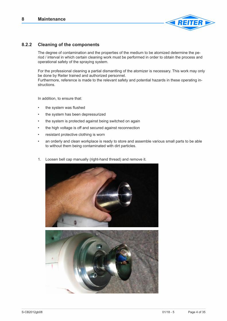
1. Loosen bell cap manually (right-hand thread) and remove it.
S-CB2012gb08 01/18 - 5 Page 5 of 35
8 Maintenance
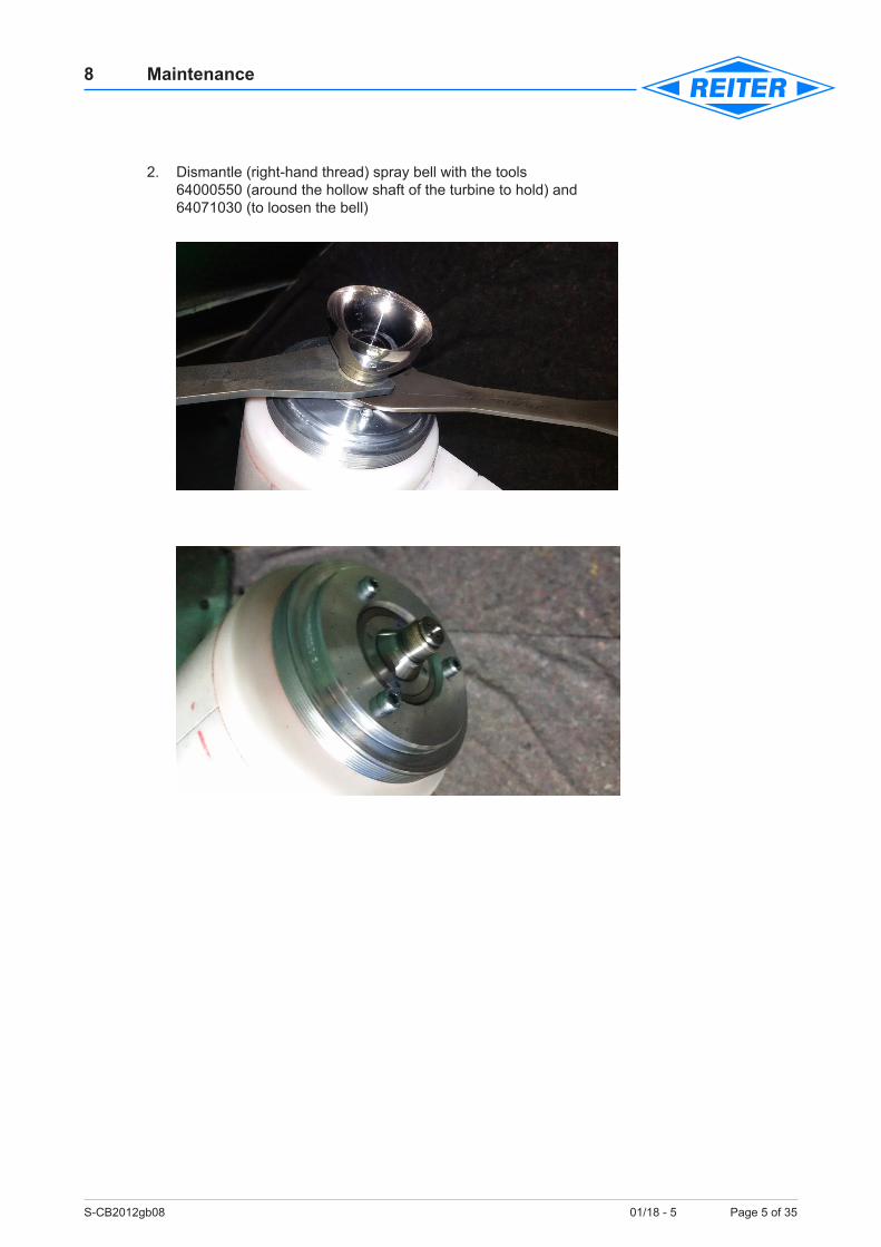
2. Dismantle (right-hand thread) spray bell with the tools 64000550 (around the hollow shaft of the turbine to hold) and 64071030 (to loosen the bell)
S-CB2012gb08 01/18 - 5 Page 6 of 35
8 Maintenance
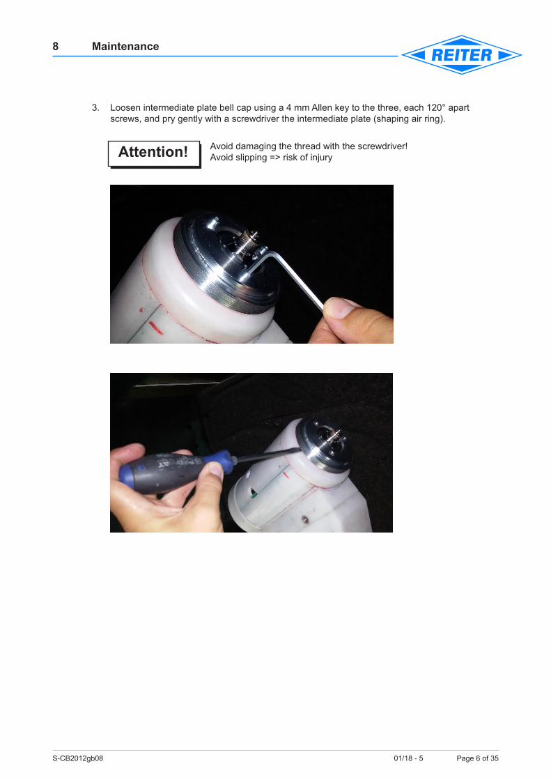
3. Loosen intermediate plate bell cap using a 4 mm Allen key to the three, each 120° apart screws, and pry gently with a screwdriver the intermediate plate (shaping air ring).
Avoid damaging the thread with the screwdriver!Avoid slipping => risk of injury
Attention!
S-CB2012gb08 01/18 - 5 Page 7 of 35
8 Maintenance
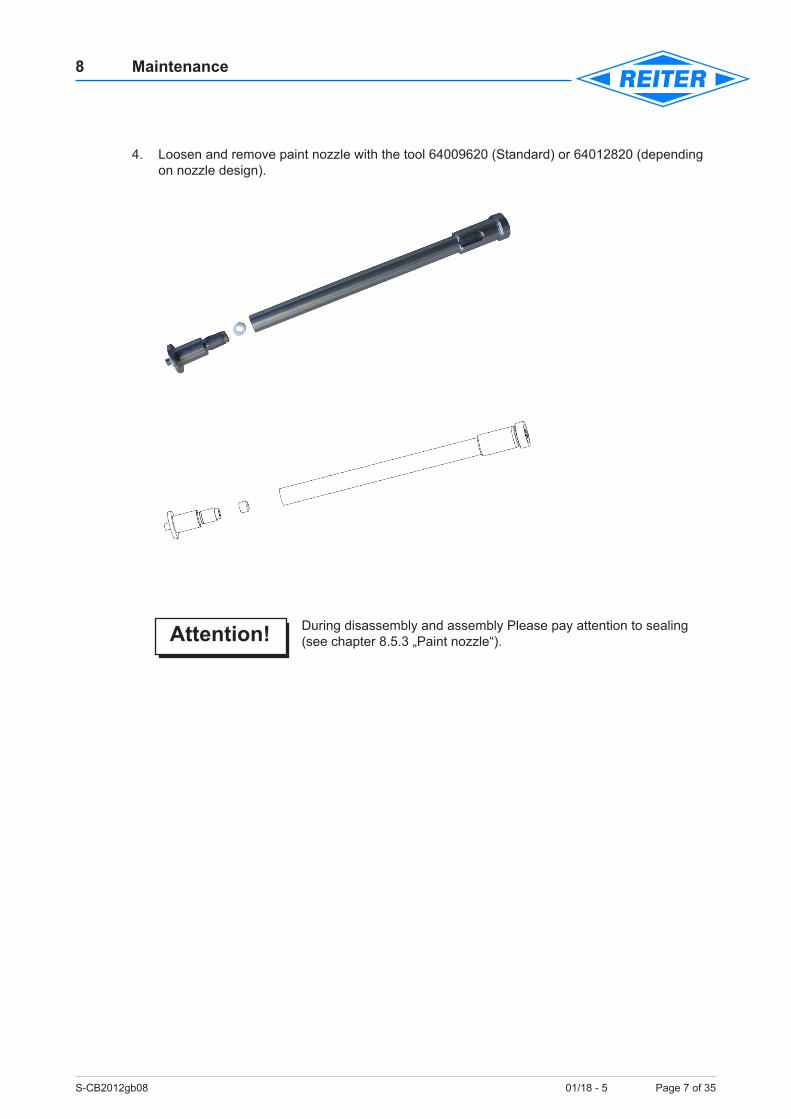
4. Loosen and remove paint nozzle with the tool 64009620 (Standard) or 64012820 (depending on nozzle design).
During disassembly and assembly Please pay attention to sealing (see chapter 8.5.3 „Paint nozzle“).
Attention!
S-CB2012gb08 01/18 - 5 Page 8 of 35
8 Maintenance
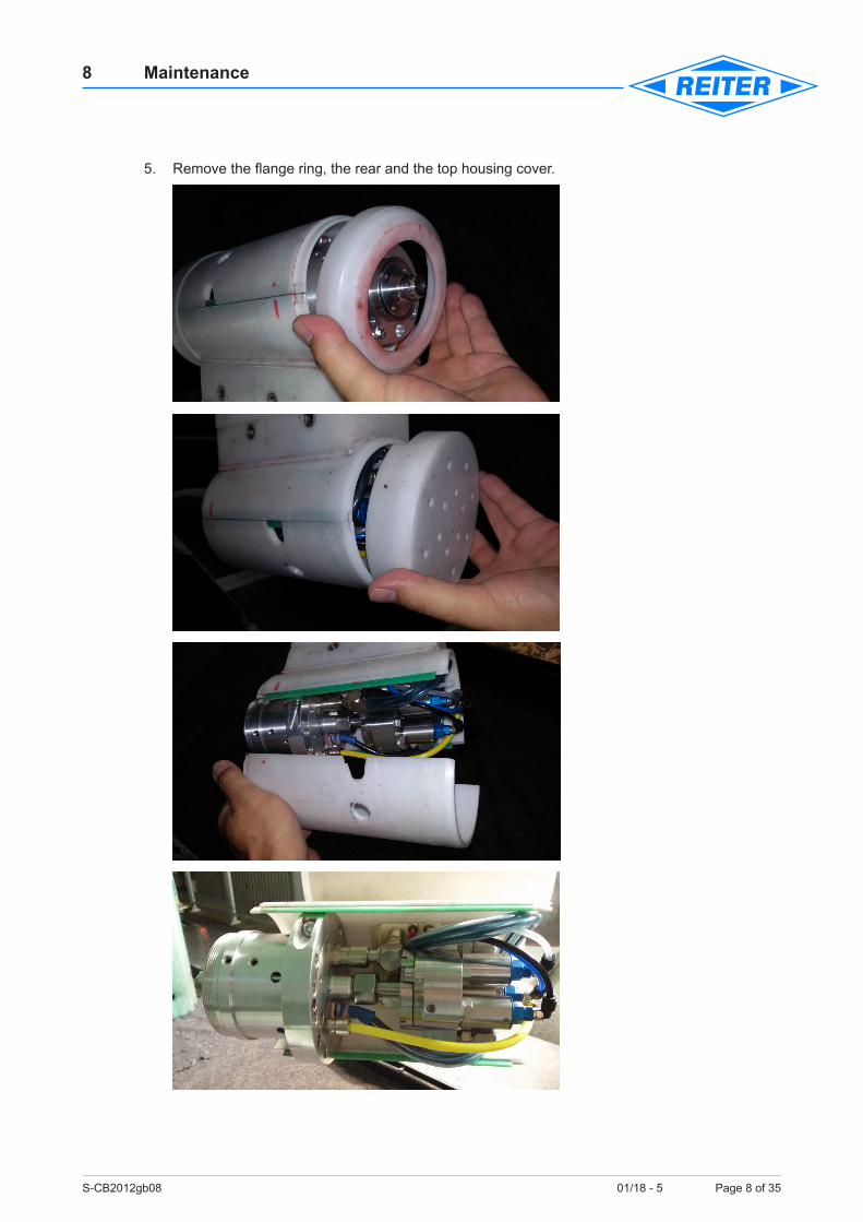
5. Remove the flange ring, the rear and the top housing cover.
S-CB2012gb08 01/18 - 5 Page 9 of 35
8 Maintenance
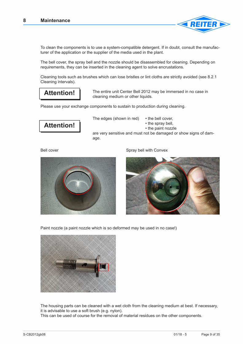
To clean the components is to use a system-compatible detergent. If in doubt, consult the manufac-turer of the application or the supplier of the media used in the plant.
The bell cover, the spray bell and the nozzle should be disassembled for cleaning. Depending on requirements, they can be inserted in the cleaning agent to solve encrustations.
Cleaning tools such as brushes which can lose bristles or lint cloths are strictly avoided (see 8.2.1 Cleaning intervals).
The entire unit Center Bell 2012 may be immersed in no case in cleaning medium or other liquids.
Please use your exchange components to sustain to production during cleaning.
The edges (shown in red) • the bell cover, • the spray bell, • the paint nozzle are very sensitive and must not be damaged or show signs of dam-age.
Bell cover Spray bell with Convex
Paint nozzle (a paint nozzle which is so deformed may be used in no case!)
The housing parts can be cleaned with a wet cloth from the cleaning medium at best. If necessary, it is advisable to use a soft brush (e.g. nylon).This can be used of course for the removal of material residues on the other components.
Attention!
Attention!

S-CB2012gb08 01/18 - 5 Page 10 of 35
8 Maintenance
Do not use hard objects such as spatula, knife or screwdriver to re-move material residues. Also, brushes made of brass or steel wire are not suitable.Make sure that no scratches occur because the components no longer allowed to be used!If you are unsure contact the application manufacturer!
Cleaning and maintenance can not always separate exactly. A damaged O-ring that stands out during cleaning, for example, actually belongs not to the clean-ing process but already for maintenance (replacement of parts).
8.3 Intervals of maintenance worksThe maintenance/check of the spraying system Center Bell 2012 must be carried out after a tight rhythm, regardless of the actual operating hours graduated. If the spraying system is used in a con-tinuous operation, then the maintenance works must be carried out at least once a week.
The time frames are empirical values, using different materials can lead to different time intervals.
8.3.1 Daily check (before or after shift start/end)Spraying bell/bell cover
• Check for damage particularly at the spraying edge of the spraying bell and the edge of the bell cover. Check run out and smooth operation of the turbine shaft.
• Check for dirt inside and outside, clean if necessary.
Externally clearly discernible damage to the spray bell/bell cap or on the atomizer indicate a collision. Here it is assumed that the turbine bearing could have been damaged.
Purely as a precaution the change unit should be replaced.Also, the terminal block for the hose package and the robot flange should be examined for damage (cracks, etc.).
During production, the display values of the current consumption (high voltage supply) and the op-erating pressure for the turbine to be observed.
Above average values indicate possible disturbances.
Higher values for current consumption for the HV supply are an indication of the degree of pollution in the atomizer area.
Higher operating pressure for the turbine and increased running noises indicate an impending bearing failure.
NoteIf the operating pressure of the turbine indicates a coming bearing damage, an operational change unit should be provided for the change (see also Chapter 9 “Storage and provision of an opera-tional change unit”).
Attention!
Attention!
S-CB2012gb08 01/18 - 5 Page 11 of 35
8 Maintenance
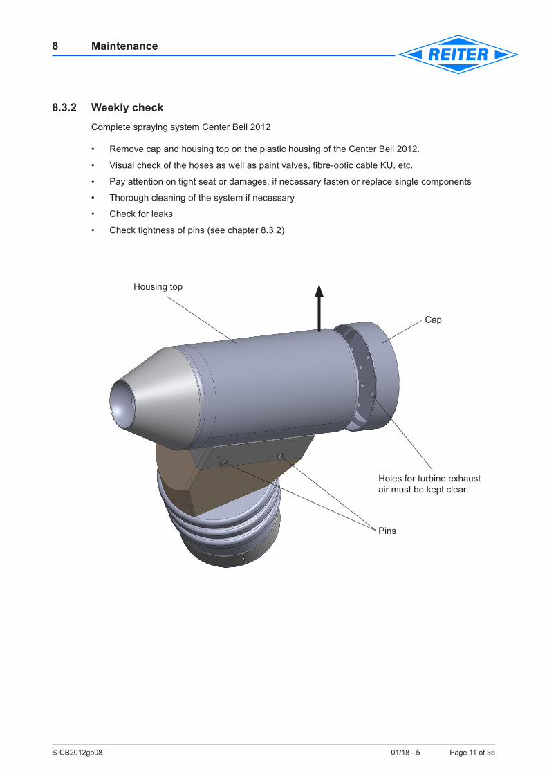
8.3.2 Weekly checkComplete spraying system Center Bell 2012
• Remove cap and housing top on the plastic housing of the Center Bell 2012.
• Visual check of the hoses as well as paint valves, fibre-optic cable KU, etc.
• Pay attention on tight seat or damages, if necessary fasten or replace single components
• Thorough cleaning of the system if necessary
• Check for leaks
• Check tightness of pins (see chapter 8.3.2)
Cap
Housing top
Holes for turbine exhaust air must be kept clear.
Pins
S-CB2012gb08 01/18 - 5 Page 12 of 35
8 Maintenance
8.3.3 Behaviour during longer operation interruptionPrior to longer interruptions such as long weekends, company holidays, short-time working, etc. the system should be thoroughly cleaned and rinsed!
Before resuming the bodyshop, after long interruptions (> 1 week), run in the turbine - in steps, according to the following table (grease distribution).
Speed: 10.000 rpm - 2 - 3 min. Speed: 20.000 rpm - 2 - 3 min. Speed: 30.000 rpm - 5 min. Speed: 40 - 45.000 rpm - 5 min.
8.3.4 Behaviour in malfunction of the spray system If the cause of the malfunction is clear to correct the interference at the attached spray system can be done any faster or at the same time as the replacement of the change unit (e.g. change spray bell).Are the causes of the malfunction can not be clearly determined, we will choose to exchange the change unit.
Attention!
S-CB2012gb08 01/18 - 5 Page 13 of 35
8 Maintenance
Attention!
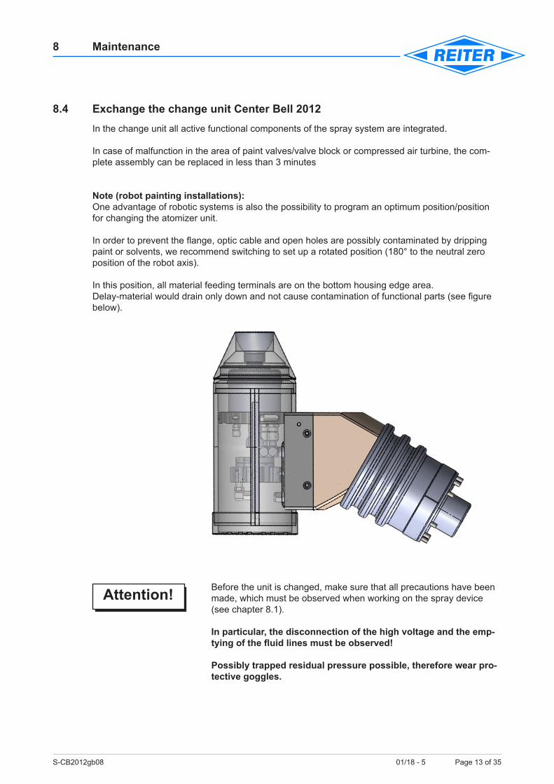
8.4 Exchange the change unit Center Bell 2012In the change unit all active functional components of the spray system are integrated.
In case of malfunction in the area of paint valves/valve block or compressed air turbine, the com-plete assembly can be replaced in less than 3 minutes
Note (robot painting installations):One advantage of robotic systems is also the possibility to program an optimum position/position for changing the atomizer unit.
In order to prevent the flange, optic cable and open holes are possibly contaminated by dripping paint or solvents, we recommend switching to set up a rotated position (180° to the neutral zero position of the robot axis).
In this position, all material feeding terminals are on the bottom housing edge area. Delay-material would drain only down and not cause contamination of functional parts (see figure below).
Before the unit is changed, make sure that all precautions have been made, which must be observed when working on the spray device (see chapter 8.1).
In particular, the disconnection of the high voltage and the emp-tying of the fluid lines must be observed!
Possibly trapped residual pressure possible, therefore wear pro-tective goggles.
S-CB2012gb08 01/18 - 5 Page 14 of 35
8 Maintenance
8.4.1 Procedure – Exchange the change unit • Switch off high voltage.
• Rinse/drain and blow out spraying system and material lines complete.
• Position spraying system in a pre-programmed position (change position).
• For security, earth system with earthing rod at the bell cover.
• All lines to the spraying system must be depressurized!
• Ensure that individual components can not be switched on.
• Unscrew 4 pins with Allen key SW4 about 3 turns.
• Remove change unit carefully. Note: O-rings may fall.
• Clean flange area if necessary.
Please make absolutely sure that no solvent/detergent or other liquids can run in the air ducts of the quick change unit or the adaptation. Also brush or a not lint-free cloths are strictly avoided (see 8.2.1 Cleaning Intervals)!
A failure of the Center Bell 2012 unit caused or accelerated by con-taminants, does not fall under the warranty conditions of the REITER GmbH + Co. KG Oberflächentechnik.
• Wipe both visible ends of the optic cables gently with clean cloth.
Attention!
S-CB2012gb08 01/18 - 5 Page 15 of 35
8 Maintenance
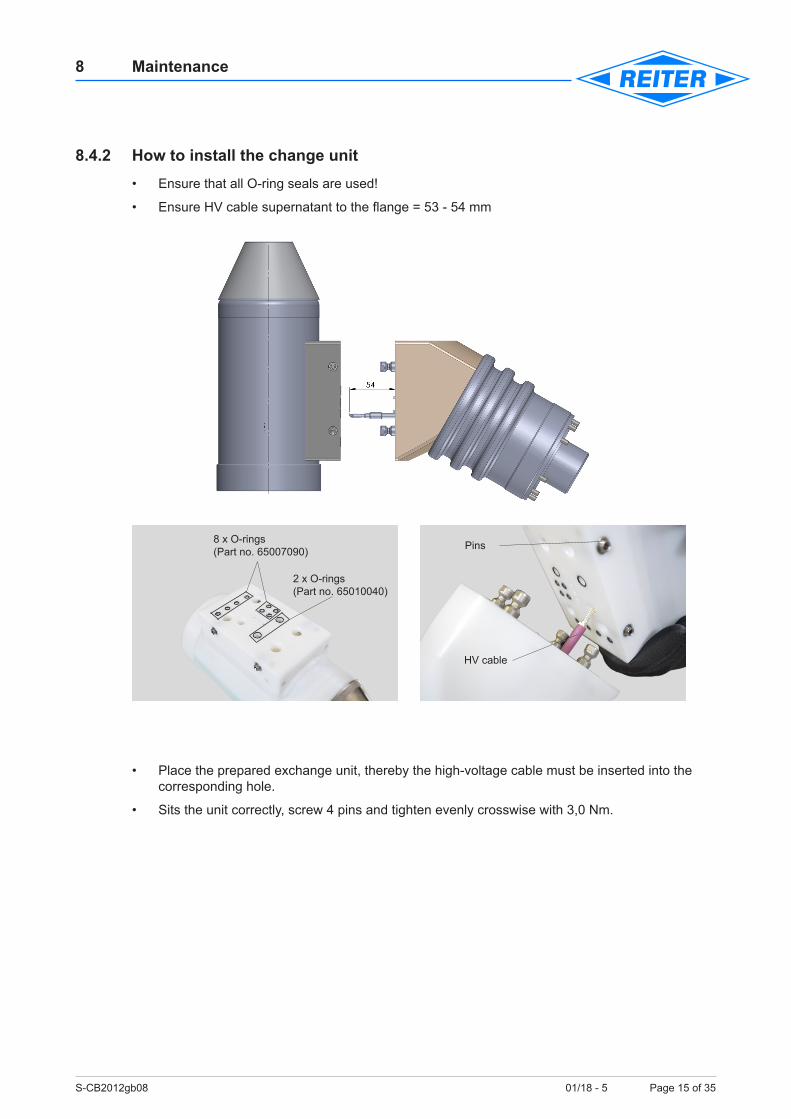
8.4.2 How to install the change unit • Ensure that all O-ring seals are used!
• Ensure HV cable supernatant to the flange = 53 - 54 mm
• Place the prepared exchange unit, thereby the high-voltage cable must be inserted into the corresponding hole.
• Sits the unit correctly, screw 4 pins and tighten evenly crosswise with 3,0 Nm.
Pins
HV cable
8 x O-rings (Part no. 65007090)
2 x O-rings (Part no. 65010040)
S-CB2012gb08 01/18 - 5 Page 16 of 35
8 Maintenance
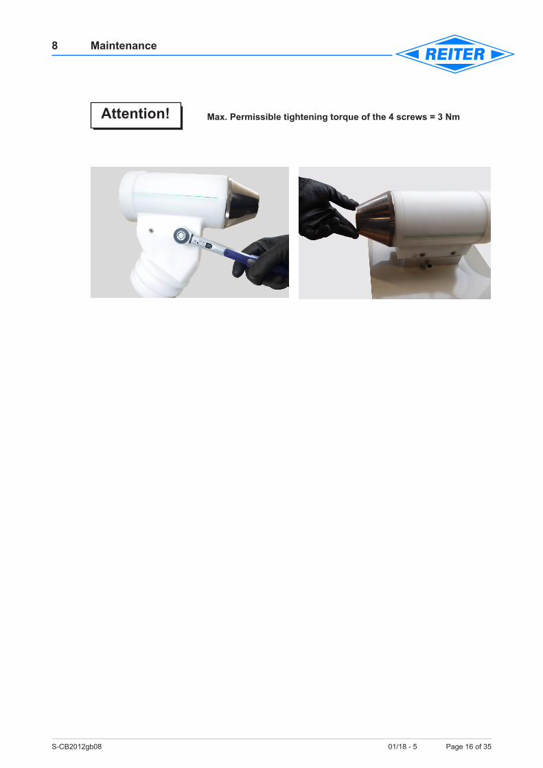
Max. Permissible tightening torque of the 4 screws = 3 Nm
Attention!
S-CB2012gb08 01/18 - 5 Page 17 of 35
8 Maintenance
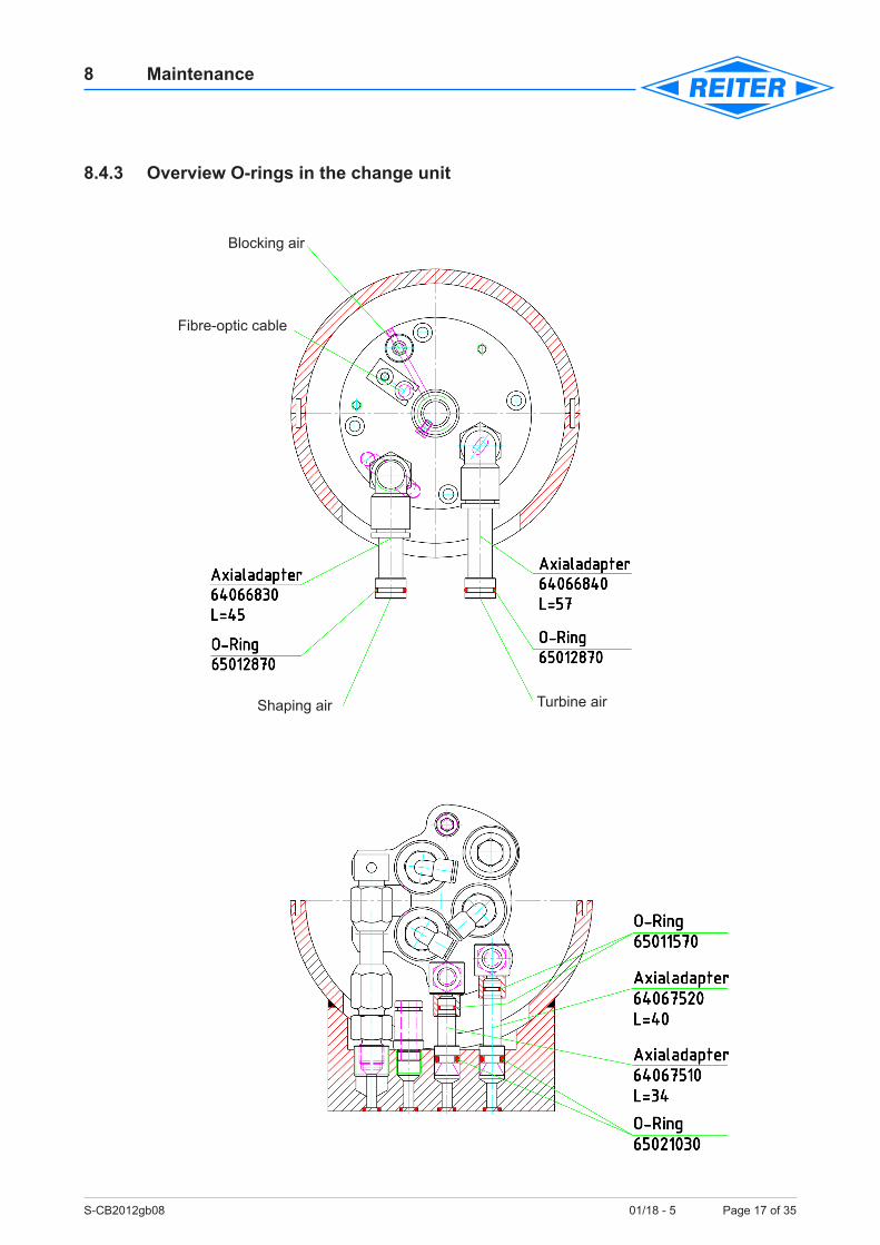
8.4.3 Overview O-rings in the change unit
Blocking air
Fibre-optic cable
Shaping air Turbine air
S-CB2012gb08 01/18 - 5 Page 18 of 35
8 Maintenance
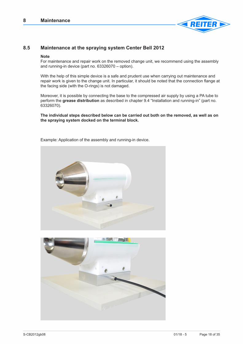
8.5 Maintenance at the spraying system Center Bell 2012NoteFor maintenance and repair work on the removed change unit, we recommend using the assembly and running-in device (part no. 63326070 – option).
With the help of this simple device is a safe and prudent use when carrying out maintenance and repair work is given to the change unit. In particular, it should be noted that the connection flange at the facing side (with the O-rings) is not damaged.
Moreover, it is possible by connecting the base to the compressed air supply by using a PA tube to perform the grease distribution as described in chapter 9.4 “Installation and running-in” (part no. 63326070).
The individual steps described below can be carried out both on the removed, as well as on the spraying system docked on the terminal block.
Example: Application of the assembly and running-in device.
S-CB2012gb08 01/18 - 5 Page 19 of 35
8 Maintenance
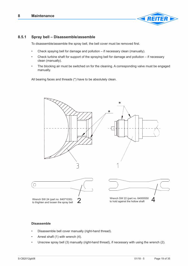
8.5.1 Spray bell – Disassemble/assembleTo disassemble/assemble the spray bell, the bell cover must be removed first.
• Check spaying bell for damage and pollution – if necessary clean (manually).
• Check turbine shaft for support of the spraying bell for damage and pollution – if necessary clean (manually).
• The blocking air must be switched on for the cleaning. A corresponding valve must be engaged manually.
All bearing faces and threads (*) have to be absolutely clean.
Disassemble
• Disassemble bell cover manually (right-hand thread).
• Arrest shaft (1) with wrench (4).
• Unscrew spray bell (3) manually (right-hand thread), if necessary with using the wrench (2).
2 4Wrench SW 24 (part no. 64071030) to thighten and loosen the spray bell
Wrench SW 22 (part no. 64000550 to hold against the hollow shaft
S-CB2012gb08 01/18 - 5 Page 20 of 35
8 Maintenance
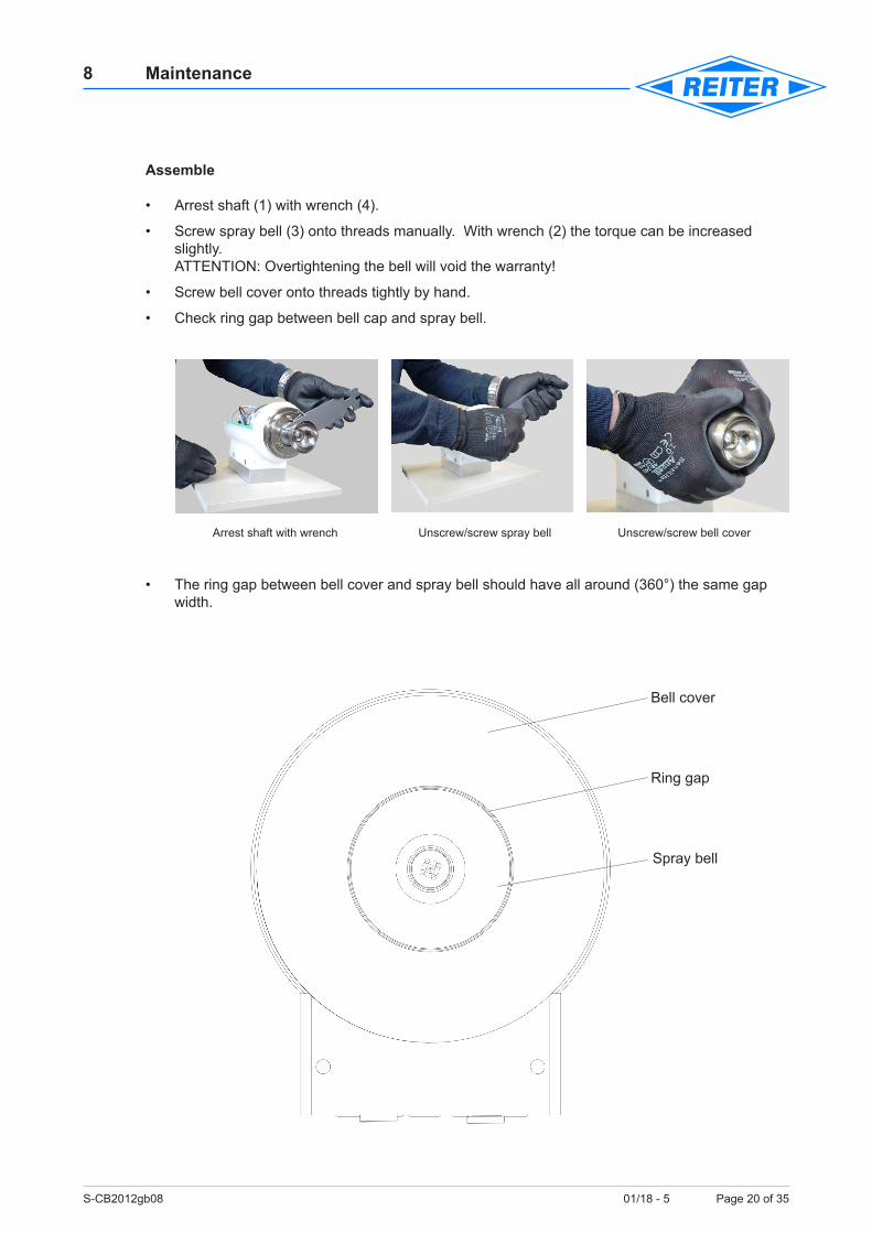
Assemble
• Arrest shaft (1) with wrench (4).
• Screw spray bell (3) onto threads manually. With wrench (2) the torque can be increased slightly. ATTENTION: Overtightening the bell will void the warranty!
• Screw bell cover onto threads tightly by hand.
• Check ring gap between bell cap and spray bell.
Arrest shaft with wrench Unscrew/screw spray bell Unscrew/screw bell cover
• The ring gap between bell cover and spray bell should have all around (360°) the same gap width.
Ring gap
Spray bell
Bell cover
S-CB2012gb08 01/18 - 5 Page 21 of 35
8 Maintenance
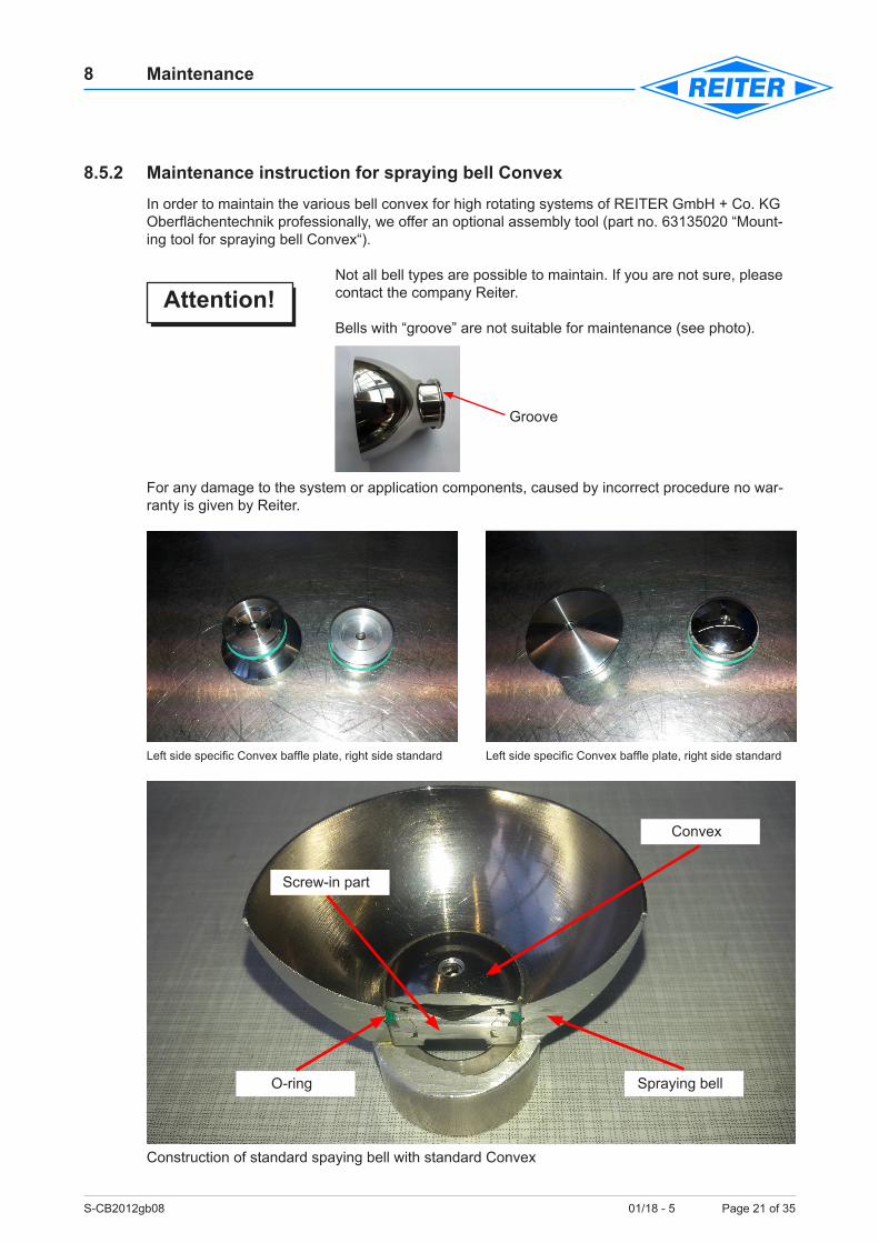
8.5.2 Maintenance instruction for spraying bell ConvexIn order to maintain the various bell convex for high rotating systems of REITER GmbH + Co. KG Oberflächentechnik professionally, we offer an optional assembly tool (part no. 63135020 “Mount-ing tool for spraying bell Convex“).
Not all bell types are possible to maintain. If you are not sure, please contact the company Reiter.
Bells with “groove” are not suitable for maintenance (see photo).
Groove
For any damage to the system or application components, caused by incorrect procedure no war-ranty is given by Reiter.
Left side specific Convex baffle plate, right side standard Left side specific Convex baffle plate, right side standard
Construction of standard spaying bell with standard Convex
Attention!
Spraying bellO-ring
Screw-in part
Convex
S-CB2012gb08 01/18 - 5 Page 22 of 35
8 Maintenance
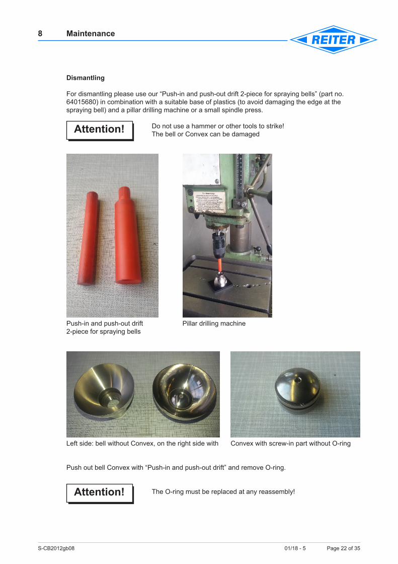
Dismantling
For dismantling please use our “Push-in and push-out drift 2-piece for spraying bells” (part no. 64015680) in combination with a suitable base of plastics (to avoid damaging the edge at the spraying bell) and a pillar drilling machine or a small spindle press.
Do not use a hammer or other tools to strike! The bell or Convex can be damaged
Push-in and push-out drift Pillar drilling machine 2-piece for spraying bells
Left side: bell without Convex, on the right side with Convex with screw-in part without O-ring
Push out bell Convex with “Push-in and push-out drift” and remove O-ring.
The O-ring must be replaced at any reassembly!
Attention!
Attention!
S-CB2012gb08 01/18 - 5 Page 23 of 35
8 Maintenance
Remove all material residues and other deposits on and in the bell with application acceptable cleaners.If you’re not sure whether a cleaner is suitable, please contact previously company Reiter.
Do not use to clean any sharp-edged tools such as knives, scraper, screwdrivers or similar. Also wire brushes made of brass or steel should not be used! A soaked with cleaner cloth or a nylon brush are a sensible alternative.
A spray bell with scratches or other damage may no longer be used.
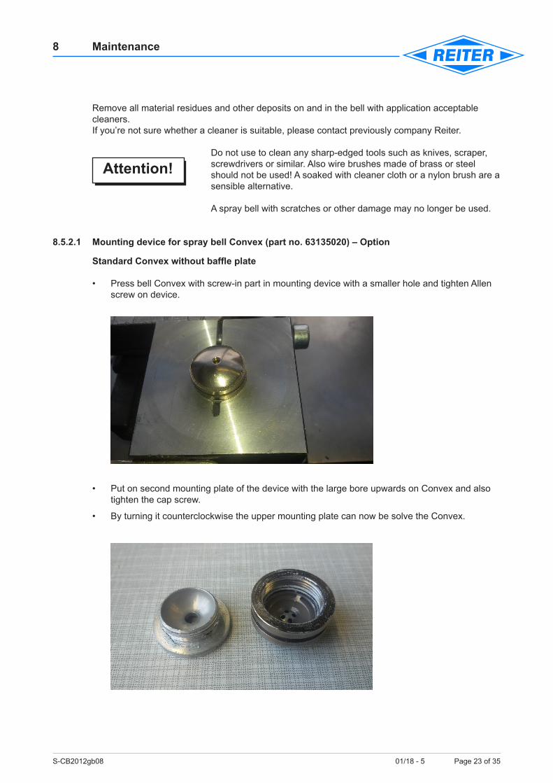
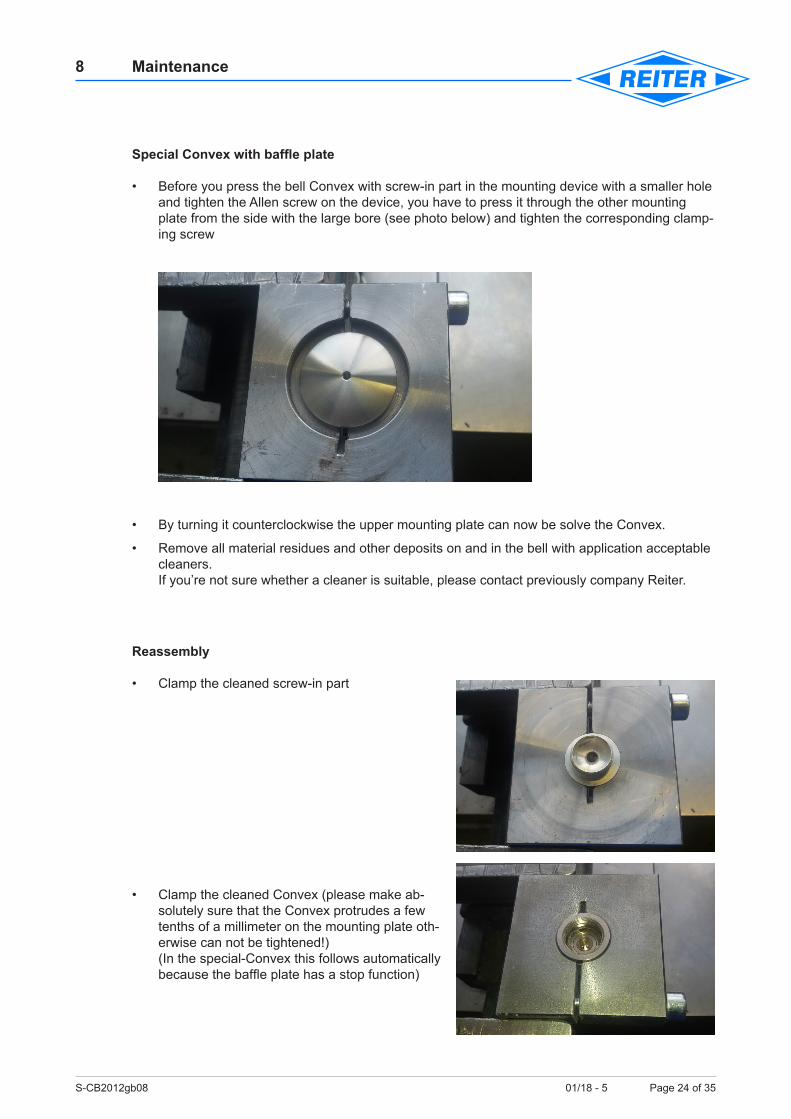
8.5.2.1 Mounting device for spray bell Convex (part no. 63135020) – Option
Standard Convex without baffle plate
• Press bell Convex with screw-in part in mounting device with a smaller hole and tighten Allen screw on device.
• Put on second mounting plate of the device with the large bore upwards on Convex and also tighten the cap screw.
• By turning it counterclockwise the upper mounting plate can now be solve the Convex.
Attention!
S-CB2012gb08 01/18 - 5 Page 24 of 35
8 Maintenance
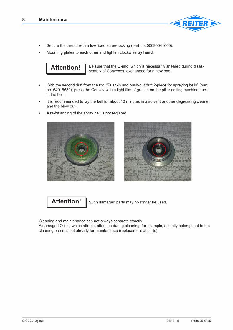
Special Convex with baffle plate
• Before you press the bell Convex with screw-in part in the mounting device with a smaller hole and tighten the Allen screw on the device, you have to press it through the other mounting plate from the side with the large bore (see photo below) and tighten the corresponding clamp-ing screw
• By turning it counterclockwise the upper mounting plate can now be solve the Convex.
• Remove all material residues and other deposits on and in the bell with application acceptable cleaners. If you’re not sure whether a cleaner is suitable, please contact previously company Reiter.
Reassembly
• Clamp the cleaned screw-in part
• Clamp the cleaned Convex (please make ab-solutely sure that the Convex protrudes a few tenths of a millimeter on the mounting plate oth-erwise can not be tightened!) (In the special-Convex this follows automatically because the baffle plate has a stop function)
S-CB2012gb08 01/18 - 5 Page 25 of 35
8 Maintenance
• Secure the thread with a low fixed screw locking (part no. 00690041600).
• Mounting plates to each other and tighten clockwise by hand.
Be sure that the O-ring, which is necessarily sheared during disas-sembly of Convexes, exchanged for a new one!
• With the second drift from the tool “Push-in and push-out drift 2-piece for spraying bells” (part no. 64015680), press the Convex with a light film of grease on the pillar drilling machine back in the bell.
• It is recommended to lay the bell for about 10 minutes in a solvent or other degreasing cleaner and the blow out.
• A re-balancing of the spray bell is not required.
Such damaged parts may no longer be used.
Cleaning and maintenance can not always separate exactly.A damaged O-ring which attracts attention during cleaning, for example, actually belongs not to the cleaning process but already for maintenance (replacement of parts).
Attention!
Attention!
S-CB2012gb08 01/18 - 5 Page 26 of 35
8 Maintenance
8.5.3 Paint nozzles – Disassemble/assembleThe spraying bell has to be dismantled prior to dismantling the paint nozzle (see chapter 8.5.1 „Spray bell – Disassemble/assemble“).
Disassemble
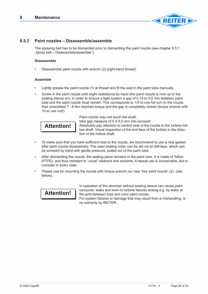
• Disassemble paint nozzle with wrench (2) (right-hand thread).
Assemble
• Lightly grease the paint nozzle (1) at thread and fit the seal in the paint tube manually.
• Screw in the paint nozzle until slight restistance by hand (the paint nozzle is now up to the sealing sleeve on). In order to ensure a tight system a gap of 0.15 to 0.5 mm between paint tube and the paint nozzle must remain. This corresponds to 1/3 to one full turn to the nozzle their prescribed 7 - 8 Nm reached torque and the gap is completely closed (torque wrench with 10-er use nut!).
Paint nozzle may not touch the shaft, take gap measure of 0,3-0,5 mm into account!Absolutely pay attention to central seat of the nozzle to the turbine hol-low shaft. Visual inspection of the end face of the turbine in the direc-tion of the hollow shaft.
• To make sure that you have sufficient bias to the nozzle, we recommend to use a new gasket after each nozzle disassembly. The used sealing collar can be set via an M4-taps, which can be screwed by hand with gentle pressure, pulled out of the paint tube.
• After dismantling the nozzle, the sealing piece remains in the paint tube. It is made of Teflon (PTFE), and thus resistant to “usual“ cleaners and solvents. A repeat use is conceivable, but to consider in every case.
• Please use for mounting the nozzle with torque wrench our new “key paint nozzle” (2) (see below).
In operation of the atomizer without sealing sleeve can cause paint carryover, leaks and even to turbine failures arising e.g. by leaks at the joint between tube and color paint nozzle. For system failures or damage that may result from a mishandling, is no warranty by REITER.
Attention!
Attention!
S-CB2012gb08 01/18 - 5 Page 27 of 35
8 Maintenance
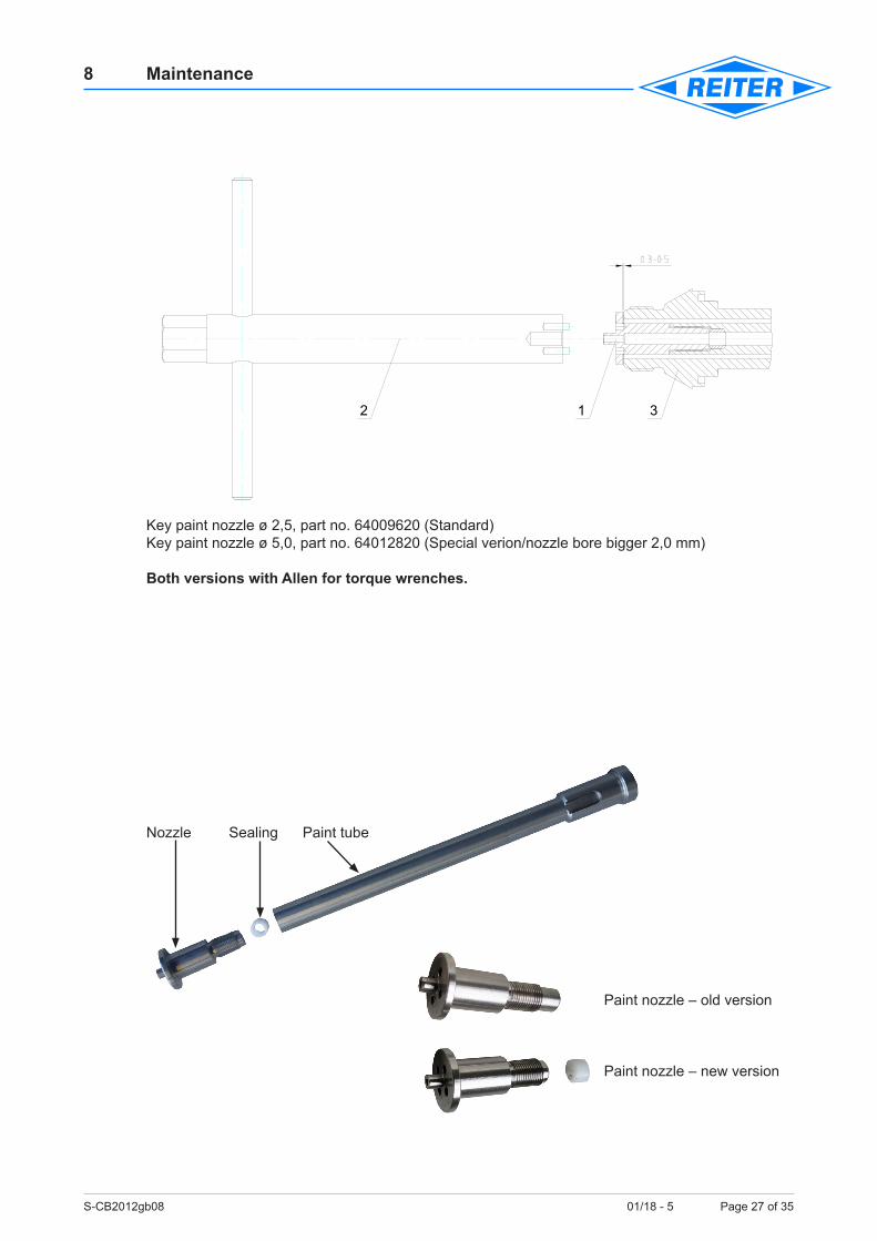
Key paint nozzle ø 2,5, part no. 64009620 (Standard)Key paint nozzle ø 5,0, part no. 64012820 (Special verion/nozzle bore bigger 2,0 mm)
Both versions with Allen for torque wrenches.
Nozzle Sealing Paint tube
Paint nozzle – old version
Paint nozzle – new version
1 32
S-CB2012gb08 01/18 - 5 Page 28 of 35
8 Maintenance
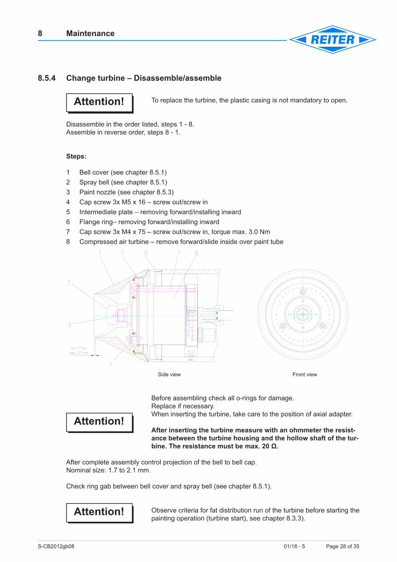
8.5.4 Change turbine – Disassemble/assemble
To replace the turbine, the plastic casing is not mandatory to open.
Disassemble in the order listed, steps 1 - 8.Assemble in reverse order, steps 8 - 1.
Steps:
1 Bell cover (see chapter 8.5.1) 2 Spray bell (see chapter 8.5.1) 3 Paint nozzle (see chapter 8.5.3) 4 Cap screw 3x M5 x 16 – screw out/screw in 5 Intermediate plate – removing forward/installing inward 6 Flange ring– removing forward/installing inward 7 Cap screw 3x M4 x 75 – screw out/screw in, torque max. 3.0 Nm 8 Compressed air turbine – remove forward/slide inside over paint tube
Side view Front view
Before assembling check all o-rings for damage.Replace if necessary.When inserting the turbine, take care to the position of axial adapter.
After inserting the turbine measure with an ohmmeter the resist-ance between the turbine housing and the hollow shaft of the tur-bine. The resistance must be max. 20 Ω.
After complete assembly control projection of the bell to bell cap.Nominal size: 1.7 to 2.1 mm.
Check ring gab between bell cover and spray bell (see chapter 8.5.1).
Observe criteria for fat distribution run of the turbine before starting the painting operation (turbine start), see chapter 8.3.3).
Attention!
Attention!
Attention!
S-CB2012gb08 01/18 - 5 Page 29 of 35
8 Maintenance
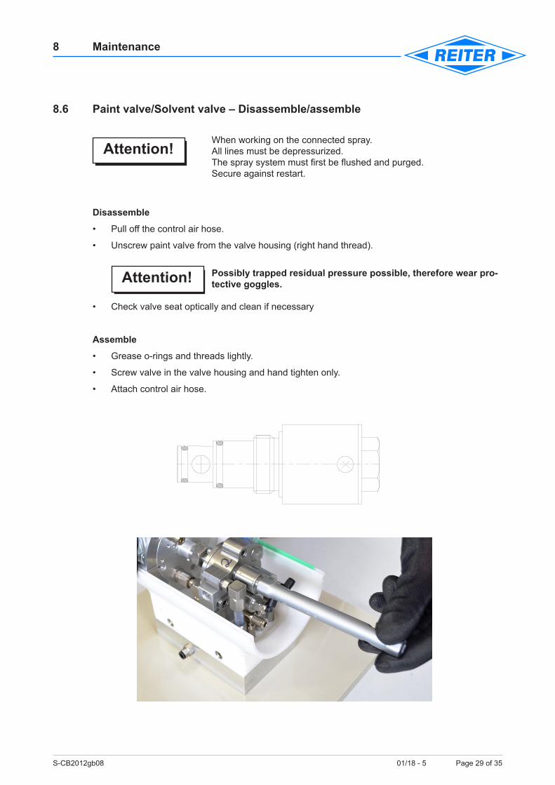
8.6 Paint valve/Solvent valve – Disassemble/assemble
When working on the connected spray.All lines must be depressurized.The spray system must first be flushed and purged. Secure against restart.
Disassemble
• Pull off the control air hose.
• Unscrew paint valve from the valve housing (right hand thread).
Possibly trapped residual pressure possible, therefore wear pro-tective goggles.
• Check valve seat optically and clean if necessary
Assemble
• Grease o-rings and threads lightly.
• Screw valve in the valve housing and hand tighten only.
• Attach control air hose.
Attention!
Attention!
S-CB2012gb08 01/18 - 5 Page 30 of 35
8 Maintenance
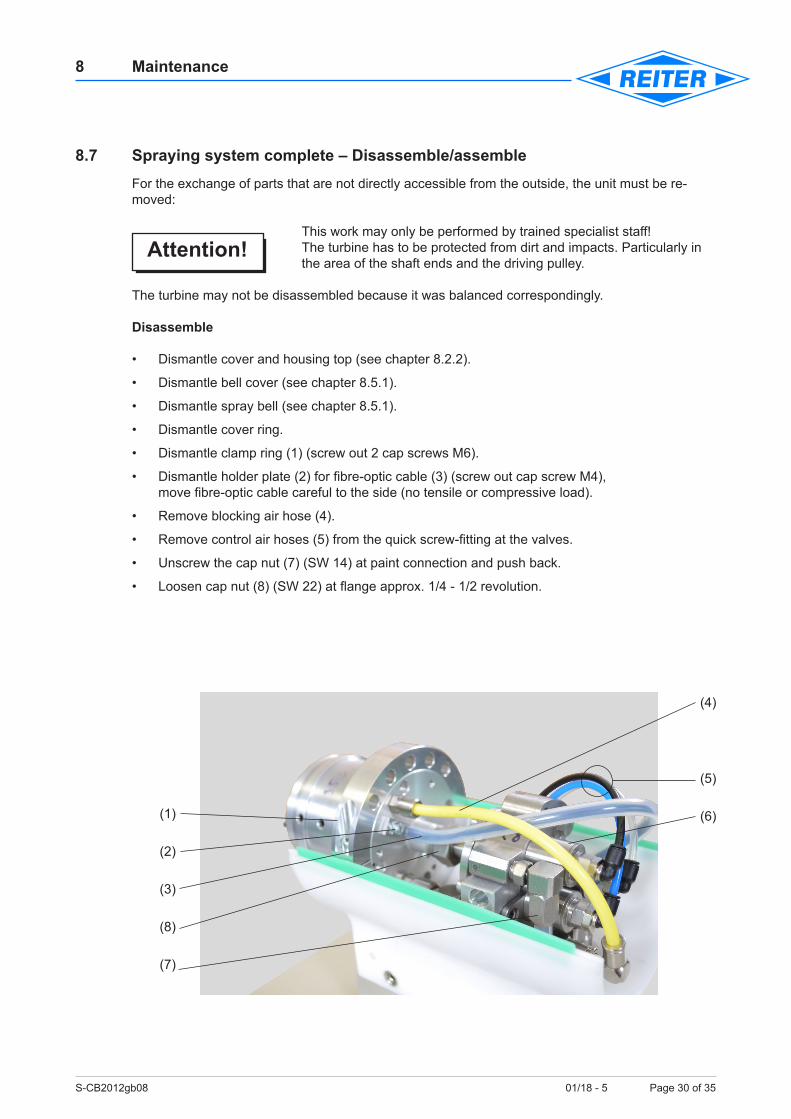
8.7 Spraying system complete – Disassemble/assembleFor the exchange of parts that are not directly accessible from the outside, the unit must be re-moved:
This work may only be performed by trained specialist staff!The turbine has to be protected from dirt and impacts. Particularly in the area of the shaft ends and the driving pulley.
The turbine may not be disassembled because it was balanced correspondingly.
Disassemble
• Dismantle cover and housing top (see chapter 8.2.2).
• Dismantle bell cover (see chapter 8.5.1).
• Dismantle spray bell (see chapter 8.5.1).
• Dismantle cover ring.
• Dismantle clamp ring (1) (screw out 2 cap screws M6).
• Dismantle holder plate (2) for fibre-optic cable (3) (screw out cap screw M4), move fibre-optic cable careful to the side (no tensile or compressive load).
• Remove blocking air hose (4).
• Remove control air hoses (5) from the quick screw-fitting at the valves.
• Unscrew the cap nut (7) (SW 14) at paint connection and push back.
• Loosen cap nut (8) (SW 22) at flange approx. 1/4 - 1/2 revolution.
Attention!
(1)
(3)
(6)
(7)
(8)
(4)
(2)
(5)
S-CB2012gb08 01/18 - 5 Page 31 of 35
8 Maintenance
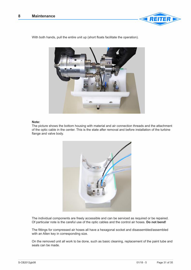
With both hands, pull the entire unit up (short floats facilitate the operation).
Note:The picture shows the bottom housing with material and air connection threads and the attachment of the optic cable in the center. This is the state after removal and before installation of the turbine flange and valve body.
The individual components are freely accessible and can be serviced as required or be repaired.Of particular note is the careful use of the optic cables and the control air hoses. Do not bend!
The fittings for compressed air hoses all have a hexagonal socket and disassembled/assembled with an Allen key in corresponding size.
On the removed unit all work to be done, such as basic cleaning, replacement of the paint tube and seals can be made.
S-CB2012gb08 01/18 - 5 Page 32 of 35
8 Maintenance
Assemble
In this, as shown above prepared lower housing part is placed the prepared assembly from above. The individual axial adapter and the paint hose must be inserted simultaneously into the holes in the housing, or in the fittings.It is helpful if the cap nut (SW 22) is applied only by hand in order to rotate the two housing parts in a position to where the axial adapter is exactly right angles to the housing bore.
It is important to ensure that the axial adapters are plugged in to the same depth.Radial rotation of the housing causes unequal insertion and lopsided axial adapter.
The correct insertion depth is achieved when the lid of the turbine rests in the clamping ring base and hem of the clamping ring is flush.When the turbine and the valve body are aligned, the upper part of the clamping ring is attached and with the two greased cap screws – M6x30 – with 6 Nm tightened. Then tighten the cap nut (SW22).
As a next step, the lightly greased paint valves are screwed (hand tighten only). Finally, the control air hose, the blocking air hose and optic cables are connected and tightened.The coloured different control air hoses are assigned to the respective paint valves and thus need to be connected to the right valve (assignment, see section 5.2.3.1).
After placing the upper housing and the cap, the change unit is ready for operation.
RemarkThis chapter has been deliberately omitted the detailed listing of individual steps, because this work is to be performed only by trained personnel.
Attention!
S-CB2012gb08 01/18 - 5 Page 33 of 35
8 Maintenance
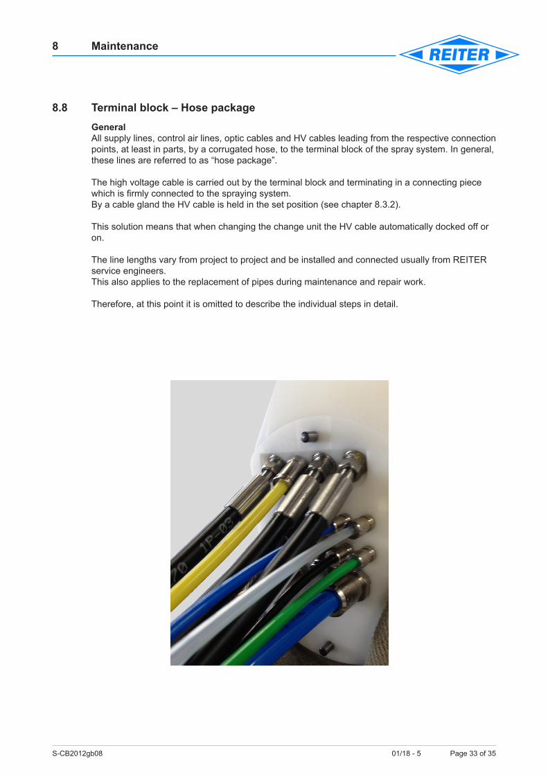
8.8 Terminal block – Hose packageGeneralAll supply lines, control air lines, optic cables and HV cables leading from the respective connection points, at least in parts, by a corrugated hose, to the terminal block of the spray system. In general, these lines are referred to as “hose package”.
The high voltage cable is carried out by the terminal block and terminating in a connecting piece which is firmly connected to the spraying system.By a cable gland the HV cable is held in the set position (see chapter 8.3.2).
This solution means that when changing the change unit the HV cable automatically docked off or on. The line lengths vary from project to project and be installed and connected usually from REITER service engineers.This also applies to the replacement of pipes during maintenance and repair work. Therefore, at this point it is omitted to describe the individual steps in detail.
S-CB2012gb08 01/18 - 5 Page 34 of 35
8 Maintenance
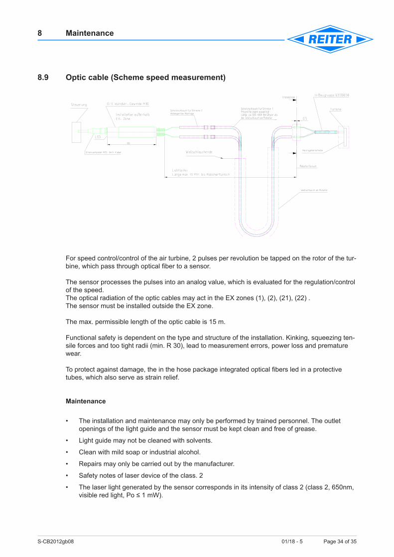
8.9 Optic cable (Scheme speed measurement)
For speed control/control of the air turbine, 2 pulses per revolution be tapped on the rotor of the tur-bine, which pass through optical fiber to a sensor.
The sensor processes the pulses into an analog value, which is evaluated for the regulation/control of the speed.The optical radiation of the optic cables may act in the EX zones (1), (2), (21), (22) .The sensor must be installed outside the EX zone.
The max. permissible length of the optic cable is 15 m. Functional safety is dependent on the type and structure of the installation. Kinking, squeezing ten-sile forces and too tight radii (min. R 30), lead to measurement errors, power loss and premature wear.
To protect against damage, the in the hose package integrated optical fibers led in a protective tubes, which also serve as strain relief.
Maintenance
• The installation and maintenance may only be performed by trained personnel. The outlet openings of the light guide and the sensor must be kept clean and free of grease.
• Light guide may not be cleaned with solvents.
• Clean with mild soap or industrial alcohol.
• Repairs may only be carried out by the manufacturer.
• Safety notes of laser device of the class. 2
• The laser light generated by the sensor corresponds in its intensity of class 2 (class 2, 650nm, visible red light, Po ≤ 1 mW).
S-CB2012gb08 01/18 - 5 Page 35 of 35
8 Maintenance
During the assembly, commissioning and operating the norm “Safety of Laser Products” EN 60825-1 para. 12.5.1/12.6.1/2 is mandatory to follow. There are only precautions necessary to prevent a continuing, direct stare into the beam. Short-lived radiation (0.25s), which can occur at random look directly, will not considered hazardous.
A hazard is present only as long as the optic cables are not connected.
The light exiting at the free end of the optical fiber is broken several times and is therefore safe for people.
S-CB2012gb09 01/18 - 5 Page 1 0f 3
9 Spare Parts
Table of Contents
9.1 General instructions ...........................................................................................................19.2 Spare parts order ...............................................................................................................19.3 Storage and provision of an operational change unit ........................................................29.3.1 Storage ..............................................................................................................................29.4 Assembly and running-in aid (part no. 63326070 – Option) ..............................................3
9.1 General instructionsA stock of the most important spare and wearing parts at the place of installation is an important prerequisite for the constant proper function and availability of the spraying system.
We provide guarantee only for original spare parts delivered by us.
In case of damage resulting from the use of non-original spare parts and accessories, any liability or guarantee provided by REITER GmbH + Co. KG Oberflächentechnik is excluded.
The stock keeping of spare parts is provision for any validity of the agreements involving system availability, service times, and guarantee or other systems performances.
9.2 Spare parts orderTo order make use of the spare parts list in the part documentation and parts lists.
All parts which are labelled with “E“ are spare parts,all parts which are labelled with “V“ are wearing parts.
For the spare parts order the following data shall indicate:
• Order number (see acknowledgment)
• Part number (see parts list)
• Designation (see parts list)
• Parts lists designation
S-CB2012gb09 01/18 - 5 Page 2 0f 3
9 Spare Parts
9.3 Storage and provision of an operational change unitThe reasons to buy a Bell Center 2012 are among other things that interruptions can be solved by disturbances in the spray system by rapid change of the system in no time.
We strongly recommend to set the replaced spray system maintenance again to have an opera-tional unit available.
9.3.1 StorageReconditioned spray systems which are stored for longer periods, should not put into operation without break-in time (grease distribution) of the air turbine.
Our many years of experience with high-speed bearings of the turbine shows that after a long time spent lubricating film breaks off in the stock.
The turbine has to go through an intake cycle.
One way to get the quick start-up of the stored atomizer unit upright is that any indications of a, emerging bearing damage (increased turbine pressure or running noise), to connect the atomizer unit on the installation and running-in aid (part no. 63326070 – option) and let run-in to 3 hours.
The installation and running-in aid is also a useful aid for the careful use of the change unit for maintenance and repair work.
When storing the change unit should also be noted:
a) Closed storage place
b) Temperature 10°C - max. 40°C
c) Humidity <65%
d) No influence of chemical gases/vapours/aerosols
S-CB2012gb09 01/18 - 5 Page 3 0f 3
9 Spare Parts
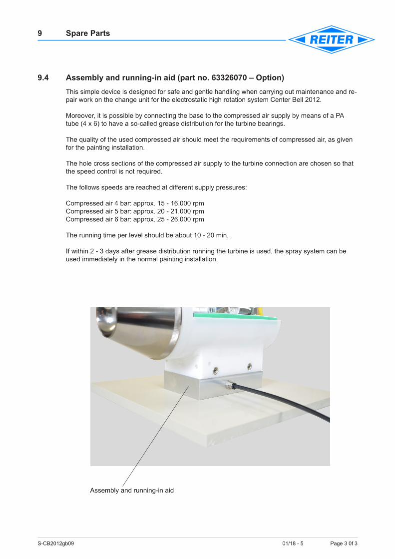
9.4 Assembly and running-in aid (part no. 63326070 – Option)This simple device is designed for safe and gentle handling when carrying out maintenance and re-pair work on the change unit for the electrostatic high rotation system Center Bell 2012.
Moreover, it is possible by connecting the base to the compressed air supply by means of a PA tube (4 x 6) to have a so-called grease distribution for the turbine bearings.
The quality of the used compressed air should meet the requirements of compressed air, as given for the painting installation.
The hole cross sections of the compressed air supply to the turbine connection are chosen so that the speed control is not required.
The follows speeds are reached at different supply pressures: Compressed air 4 bar: approx. 15 - 16.000 rpmCompressed air 5 bar: approx. 20 - 21.000 rpmCompressed air 6 bar: approx. 25 - 26.000 rpm The running time per level should be about 10 - 20 min.
If within 2 - 3 days after grease distribution running the turbine is used, the spray system can be used immediately in the normal painting installation.
Assembly and running-in aid