Embed Size (px)
Citation preview

PRICE: $25.00
OPERATING MANUAL
RANGER (RRS SERIES)
RECTIFIERS AND SHELVES
www.unipowertelecom.com
Manual No. RRS-800-5 © 2002 UNIPOWER Corp.All Rights Reserved
UNIPOWER Telecom, Division of UNIPOWER Corporation
03/03/04 RRS-Ranger-Man
NORTH AMERICA • 3900 Coral Ridge Drive, Coral Springs, Florida 33065, USA • Tel: +1 954-346-2442 • Fax: +1 954-340-7901 • [email protected] • Parkland Business Centre, Chartwell Road, Lancing BN15 8UE, ENGLAND • Tel: +44(0)1903 768200 • Fax: +44(0)1903 764540 • [email protected]
CONTENTS
SECTION TOPIC PAGE
1.0 Introduction 1
2.0 Features 3
3.0 Product Line 3
4.0 Safety Warnings 4
5.0 Warranty 4
6.0 Unpacking and Inspection 5
7.0 Description of Operation 5
8.0 Front Panel Description 6
9.0 Rectifier Module Specifications 6
10.0 Description of Features and Options 9
11.0 Mechanical Specifications 10
12.0 Safety and Industry Standards 11
13.0 Operating Information 11
14.0 Parallel Operation 15
15.0 Control & Supervisory Signal Connections 16
16.0 Rectifier Module Connections 16
17.0 Description of Control & Supervisory Signals 18
18.0 Installation 19
19.0 Maintenance 20
20.0 Rectifier & Shelf Setup and Testing 20
21.0 Troubleshooting Guide 24
Appendix Application Note: Three-Phase Power with A1
Unipower Front-End and Rectifier
ILLUSTRATIONS
FIGURE TITLE PAGE
1 Ranger Rectifier Modules and 23” Shelf 2
2 Ranger Rectifier Module Block Diagram 2
3 Front Panel of Ranger Rectifier Module 7
4 Ranger Series Mechanical Dimensions 7
5 AC Input and DC Output Connections 12
6 Rated Output Current vs. Ambient Temperature 14
7 Remote Sensing Connection 14
8 Parallel Connection of Ranger Shelves 17
9 Rectifier Module Pin Connections 17
10 Checking AC Good & DC Good Outputs 22
11 Checking Remote Adjust Input 22
1
RANGER SERIESOPERATING MANUAL
1.0 INTRODUCTION
This operating manual should be read through carefully before installing and operat-ing the Ranger rectifiers.
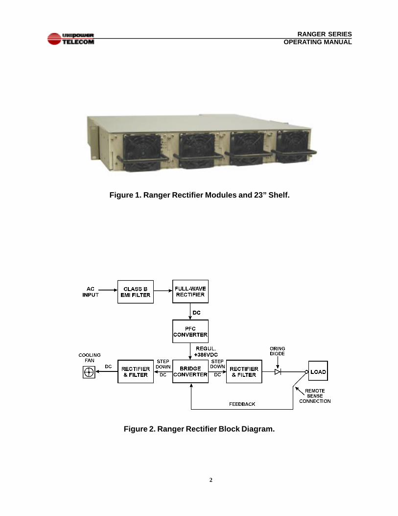
The Ranger (RRS Series) rectifier modules and shelves operate as a complete hot-swap power system for charging a 48V or 24V lead-acid battery or directly poweringa load. See Figure 1. Each rectifier module produces up to 50 amperes at 54.4VDC(48V version) or 100 amperes at 27.2VDC (24V version). The 48V version isfactory set to 54.4VDC output and the 24V version is factory set to 27.2VDC.Three rectifiers in a 19-inch shelf produce up to 150A at 54.4VDC or 300A at27.2VDC; four rectifiers in a 23-inch shelf produce up to 200A at 54.4VDC or 400Aat 27.2VDC. The rectifiers have single-wire active load sharing for automatic para-lleling, and output ORing diodes which permit hot-swap addition or replacement ofmodules while the power system is operating. A shelf with rectifier modules canalso be operated as an N+1 redundant power system with hot-swap, no-downtimereplacement of a faulty module.
These power systems operate worldwide with a 170 to 264VAC input range at 47 to63Hz and a separate AC input connection to each rectifier module. The moduleshave input power factor correction and Class B EMI input filters. The output voltageis tightly regulated and precisely adjustable over a range of 47 to 57VDC or 23.5 to28.5VDC by means of a front panel, 12-turn potentiometer. Each module also has aremote analog input which can be used to adjust the output voltage over the samerange. Using an external power controller in conjunction with this input permitsautomatic battery voltage control of equalize and float voltages together with tem-perature-compensated charging. The rectifiers can operate into a zero-voltage(dead) battery or short circuit without harm to the system. The output overloadcharacteristic is a constant current output at 105% of rated output current. Theoutput is floating with respect to frame or AC grounds.
A 25-pin interface subminiature D connector on the backplane of the shelf furnishescontrol and monitoring inputs and outputs. An enable input turns the entire shelfoutput off or on. Remote sensing connections provide precise regulation at thebattery or other point of load. Other control signals are AC good, DC good andthermal alarm logic outputs; analog voltage current monitor outputs; and analogvoltage remote adjust inputs - - all for each individual rectifier module.
Front-panel green LEDs indicate AC power good and DC power good for each
OPERATING MANUALRANGER (RRS SERIES) RECTIFIERS AND SHELVES
2
RANGER SERIESOPERATING MANUAL
Figure 1. Ranger Rectifier Modules and 23” Shelf.
Figure 2. Ranger Rectifier Block Diagram.
3
RANGER SERIESOPERATING MANUAL
rectifier module. The rectifier modules and shelves are safety agency certified andCE marked.
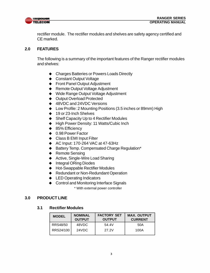
2.0 FEATURES
The following is a summary of the important features of the Ranger rectifier modulesand shelves:
u Charges Batteries or Powers Loads Directlyu Constant Output Voltageu Front Panel Output Adjustmentu Remote Output Voltage Adjustmentu Wide Range Output Voltage Adjustmentu Output Overload Protectedu 48VDC and 24VDC Versionsu Low Profile: 2 Mounting Positions (3.5 inches or 89mm) Highu 19 or 23-Inch Shelvesu Shelf Capacity Up to 4 Rectifier Modulesu High Power Density: 11 Watts/Cubic Inchu 85% Efficiencyu 0.98 Power Factoru Class B EMI Input Filteru AC Input: 170-264 VAC at 47-63Hzu Battery Temp. Compensated Charge Regulation*u Remote Sensingu Active, Single-Wire Load Sharingu Integral ORing Diodesu Hot-Swappable Rectifier Modulesu Redundant or Non-Redundant Operationu LED Operating Indicatorsu Control and Monitoring Interface Signals
* With external power controller
3.0 PRODUCT LINE
3.1 Rectifier Modules
RRS48/50 48VDC 54.4V 50A
RRS24/100 24VDC 27.2V 100A
MODEL NOMINALOUTPUT
MAX. OUTPUTCURRENT
FACTORY SETOUTPUT
4
RANGER SERIESOPERATING MANUAL
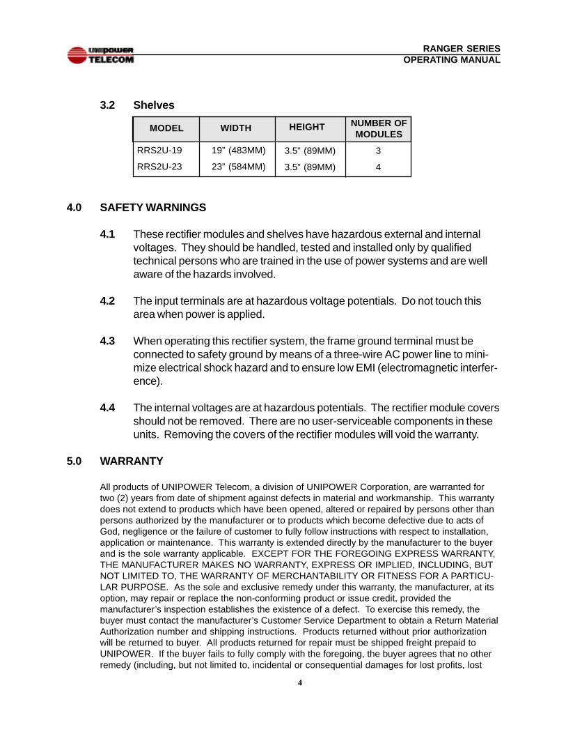
3.2 Shelves
4.0 SAFETY WARNINGS
4.1 These rectifier modules and shelves have hazardous external and internalvoltages. They should be handled, tested and installed only by qualifiedtechnical persons who are trained in the use of power systems and are wellaware of the hazards involved.
4.2 The input terminals are at hazardous voltage potentials. Do not touch thisarea when power is applied.
4.3 When operating this rectifier system, the frame ground terminal must beconnected to safety ground by means of a three-wire AC power line to mini-mize electrical shock hazard and to ensure low EMI (electromagnetic interfer-ence).
4.4 The internal voltages are at hazardous potentials. The rectifier module coversshould not be removed. There are no user-serviceable components in theseunits. Removing the covers of the rectifier modules will void the warranty.
5.0 WARRANTY
All products of UNIPOWER Telecom, a division of UNIPOWER Corporation, are warranted fortwo (2) years from date of shipment against defects in material and workmanship. This warrantydoes not extend to products which have been opened, altered or repaired by persons other thanpersons authorized by the manufacturer or to products which become defective due to acts ofGod, negligence or the failure of customer to fully follow instructions with respect to installation,application or maintenance. This warranty is extended directly by the manufacturer to the buyerand is the sole warranty applicable. EXCEPT FOR THE FOREGOING EXPRESS WARRANTY,THE MANUFACTURER MAKES NO WARRANTY, EXPRESS OR IMPLIED, INCLUDING, BUTNOT LIMITED TO, THE WARRANTY OF MERCHANTABILITY OR FITNESS FOR A PARTICU-LAR PURPOSE. As the sole and exclusive remedy under this warranty, the manufacturer, at itsoption, may repair or replace the non-conforming product or issue credit, provided themanufacturer’s inspection establishes the existence of a defect. To exercise this remedy, thebuyer must contact the manufacturer’s Customer Service Department to obtain a Return MaterialAuthorization number and shipping instructions. Products returned without prior authorizationwill be returned to buyer. All products returned for repair must be shipped freight prepaid toUNIPOWER. If the buyer fails to fully comply with the foregoing, the buyer agrees that no otherremedy (including, but not limited to, incidental or consequential damages for lost profits, lost
RRS2U-19 19” (483MM)
RRS2U-23 23” (584MM)
NUMBER OFMODULES
MODEL WIDTH HEIGHT
3.5” (89MM) 3
3.5” (89MM) 4
5
RANGER SERIESOPERATING MANUAL
sales, injury to person or property or any other incidental or consequential losses) shall beavailable to the buyer.
6.0 UNPACKING AND INSPECTION
6.1 This Ranger Series Rectifier System was carefully tested, inspected andpackaged for shipment from our factory. Upon receipt of the unit it should becarefully unpacked and inspected for any damage in shipment.
6.2 If there is evidence of damage, do not attempt to test the unit. The freightcarrier should be notified immediately and a claim for the cost of the rectifiersystem should be filed with the carrier for direct reimbursement. Be sure toinclude the model and serial number of the damaged unit in all correspon-dence with the freight carrier. Also save the shipping carton and packingmaterial as evidence of damage for the freight carrier’s inspection.
6.3 UNIPOWER Telecom will cooperate fully in case of any shipping damageinvestigation.
6.4 Always save the packing materials for later use in shipping the unit. Nevership the rectifier system without proper packing.
7.0 DESCRIPTION OF OPERATION
7.1 Block Diagram. A simplified diagram of a Ranger Rectifier Module is shownin Figure 2. The AC input first goes through a Class B EMI filter then to afull-wave rectifier and high-frequency (70kHz) power factor correction (PFC)converter. The output of the PFC converter is a regulated DC voltage atapproximately +385V. This voltage is converted down to either 48VDC or24VDC nominal, depending on the model. This is done by a bridge-config-ured converter operating at 70 kHz. The output of this converter goesthrough a rectifier, filter and ORing diode to the module output. Feedbackfrom the remote sense terminals goes back to the converter’s pulse-widthmodulator which regulates the output voltage and keeps it constant.
7.2 Power Factor Correction. This high-frequency converter circuit achieves apower factor of 0.98 by forcing the AC input current into a sinusoidal wave-form, in phase with the input voltage. The input current is a smooth sinewave of much lower amplitude than the normal series of high-amplitude, inputcurrent pulses that are present in a unit without power factor correction. Theresult is lower RMS input current for a given output power level.
6
RANGER SERIESOPERATING MANUAL
7.3 Cooling Fan. Another output from the bridge converter is rectified, filteredand used to power the DC ball bearing cooling fan on the rectifier module.
7.4 Interface Signals. The rectifier incorporates a number of interface controland supervisory signals which operate off internal circuits and are brought tothe outside. These include remote enable, which enables or inhibits theentire shelf, and a current share connection which permits operating the shelfin parallel with other shelves for increased power. Other signals brought outof the shelf for each rectifier module include thermal alarm, AC good, DCgood, current monitor and a remote adjust which permits adjustment of eachrectifier output voltage by means of an external analog control voltage.
8.0 FRONT PANEL DESCRIPTION
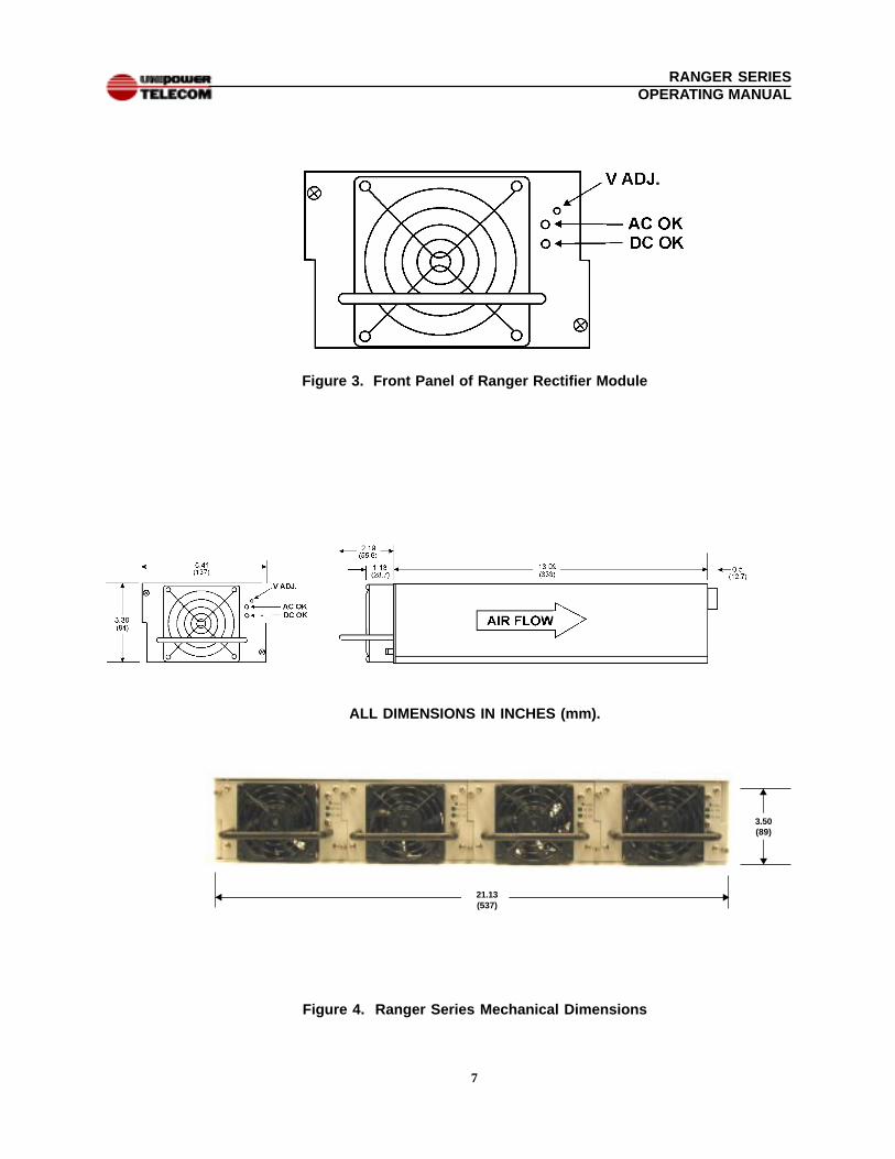
The front panel of a Ranger rectifier module is shown in Figure 3. From top tobottom are: output voltage adjustment potentiometer (12-turn), AC Good LED(green) and DC Good LED (green). A single 80 mm fan cools the module.
9.0 RECTIFIER MODULE SPECIFICATIONS
Specifications for a Single Rectifier Module. Typical at 230VAC Line, Full Load and 25°C UnlessOtherwise Noted.
INPUTVoltage Range ............................................... 170-264VACPower Factor ................................................. 0.98Total Harmonic Distortion, Max. .................... 5%Frequency ..................................................... 47-63HzInrush Current Limiting ................................. 25A PeakInput Current, Full Load ................................ 14.4A@230VACEMI Filter, Conducted ................................... FCC20780 pt. 15J Curve B
................................... EN55022 Curve BFast Transients, Line-Line ............................. EN61000-4-4, Level 3Input Surges, Line-Line ................................. EN61000-4-5, Level 2Input Surges, Line-Ground ........................... EN61000-4-5, Level 3Analog Voltage Adjust ................................... 0 to +5V
OUTPUTCurrent & Voltage1 ......................................... [email protected]
......................................... [email protected] Adjustment Range, 48V Nominal ..... 47.0-57.0VDC
24V Nominal ..... 23.5-28.5VDC
7
RANGER SERIESOPERATING MANUAL
Figure 4. Ranger Series Mechanical Dimensions
Figure 3. Front Panel of Ranger Rectifier Module
3.50(89)
21.13(537)
u
u
u
u
ALL DIMENSIONS IN INCHES (mm).
8
RANGER SERIESOPERATING MANUAL
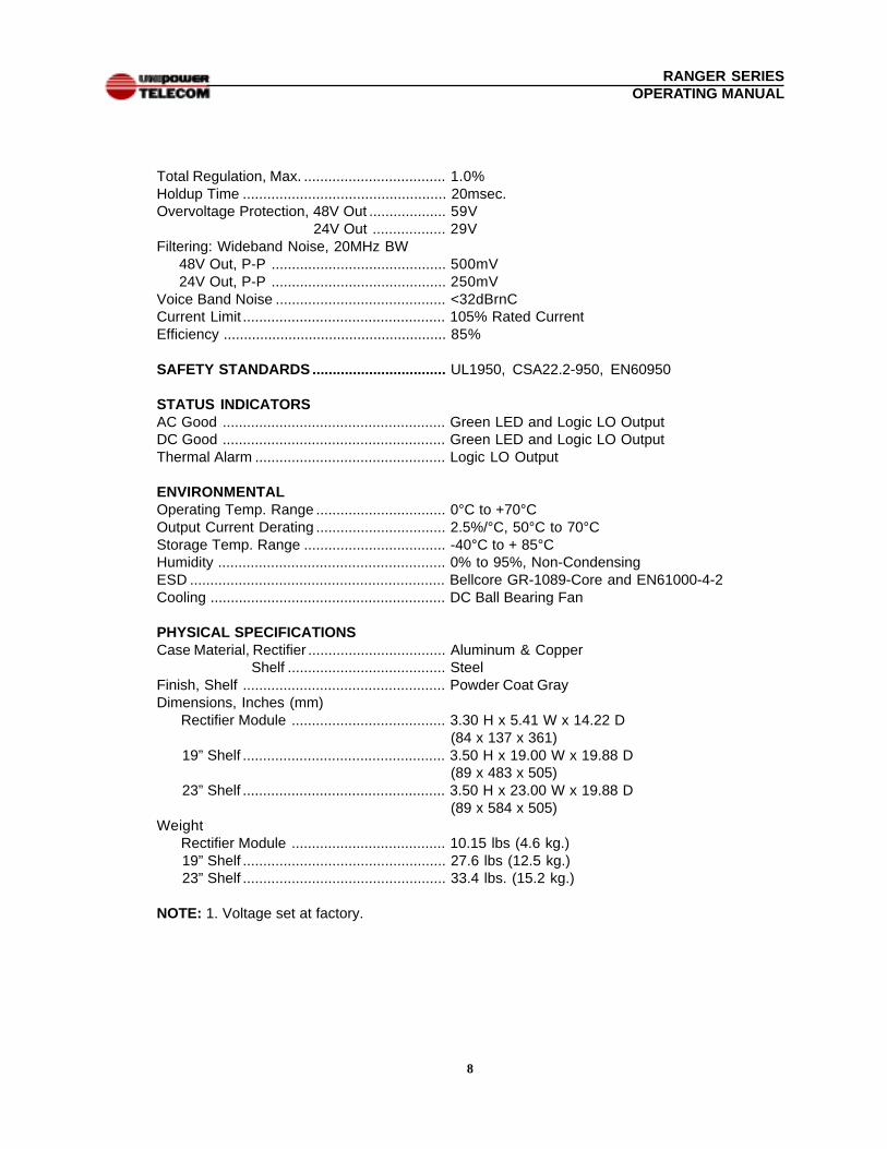
Total Regulation, Max. ................................... 1.0%Holdup Time .................................................. 20msec.Overvoltage Protection, 48V Out ................... 59V 24V Out .................. 29VFiltering: Wideband Noise, 20MHz BW 48V Out, P-P ........................................... 500mV 24V Out, P-P ........................................... 250mVVoice Band Noise .......................................... <32dBrnCCurrent Limit .................................................. 105% Rated CurrentEfficiency ....................................................... 85%
SAFETY STANDARDS ................................. UL1950, CSA22.2-950, EN60950
STATUS INDICATORSAC Good ....................................................... Green LED and Logic LO OutputDC Good ....................................................... Green LED and Logic LO OutputThermal Alarm ............................................... Logic LO Output
ENVIRONMENTALOperating Temp. Range ................................ 0°C to +70°COutput Current Derating ................................ 2.5%/°C, 50°C to 70°CStorage Temp. Range ................................... -40°C to + 85°CHumidity ........................................................ 0% to 95%, Non-CondensingESD ............................................................... Bellcore GR-1089-Core and EN61000-4-2Cooling .......................................................... DC Ball Bearing Fan
PHYSICAL SPECIFICATIONSCase Material, Rectifier .................................. Aluminum & Copper
Shelf ....................................... SteelFinish, Shelf .................................................. Powder Coat GrayDimensions, Inches (mm) Rectifier Module ...................................... 3.30 H x 5.41 W x 14.22 D
(84 x 137 x 361) 19” Shelf .................................................. 3.50 H x 19.00 W x 19.88 D
(89 x 483 x 505) 23” Shelf .................................................. 3.50 H x 23.00 W x 19.88 D
(89 x 584 x 505)Weight Rectifier Module ...................................... 10.15 lbs (4.6 kg.) 19” Shelf .................................................. 27.6 lbs (12.5 kg.) 23” Shelf .................................................. 33.4 lbs. (15.2 kg.)
NOTE: 1. Voltage set at factory.
9
RANGER SERIESOPERATING MANUAL
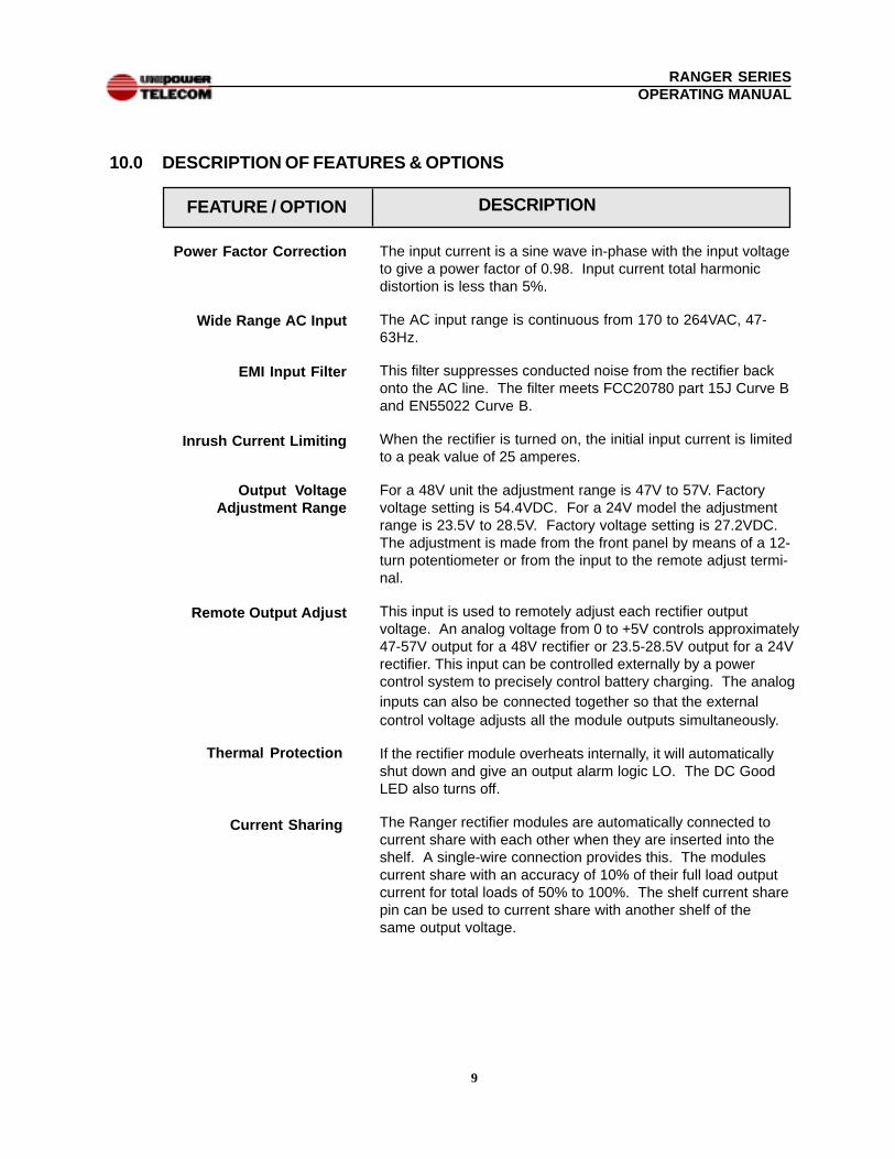
10.0 DESCRIPTION OF FEATURES & OPTIONS
DESCRIPTION
The input current is a sine wave in-phase with the input voltageto give a power factor of 0.98. Input current total harmonicdistortion is less than 5%.
The AC input range is continuous from 170 to 264VAC, 47-63Hz.
This filter suppresses conducted noise from the rectifier backonto the AC line. The filter meets FCC20780 part 15J Curve Band EN55022 Curve B.
When the rectifier is turned on, the initial input current is limitedto a peak value of 25 amperes.
For a 48V unit the adjustment range is 47V to 57V. Factoryvoltage setting is 54.4VDC. For a 24V model the adjustmentrange is 23.5V to 28.5V. Factory voltage setting is 27.2VDC.The adjustment is made from the front panel by means of a 12-turn potentiometer or from the input to the remote adjust termi-nal.
This input is used to remotely adjust each rectifier outputvoltage. An analog voltage from 0 to +5V controls approximately47-57V output for a 48V rectifier or 23.5-28.5V output for a 24Vrectifier. This input can be controlled externally by a powercontrol system to precisely control battery charging. The analoginputs can also be connected together so that the externalcontrol voltage adjusts all the module outputs simultaneously.
If the rectifier module overheats internally, it will automaticallyshut down and give an output alarm logic LO. The DC GoodLED also turns off.
The Ranger rectifier modules are automatically connected tocurrent share with each other when they are inserted into theshelf. A single-wire connection provides this. The modulescurrent share with an accuracy of 10% of their full load outputcurrent for total loads of 50% to 100%. The shelf current sharepin can be used to current share with another shelf of thesame output voltage.
Power Factor Correction
Wide Range AC Input
EMI Input Filter
Inrush Current Limiting
Output VoltageAdjustment Range
FEATURE / OPTION
Remote Output Adjust
Thermal Protection
Current Sharing
10
RANGER SERIESOPERATING MANUAL
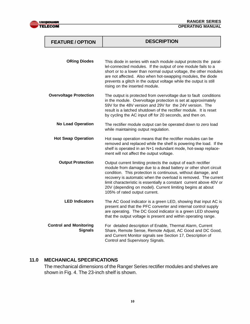
This diode in series with each module output protects the paral-lel-connected modules. If the output of one module fails to ashort or to a lower than normal output voltage, the other modulesare not affected. Also when hot-swapping modules, the diodeprevents a glitch in the output voltage while the output is stillrising on the inserted module.
The output is protected from overvoltage due to fault conditionsin the module. Overvoltage protection is set at approximately59V for the 48V version and 29V for the 24V version. Theresult is a latched shutdown of the rectifier module. It is resetby cycling the AC input off for 20 seconds, and then on.
The rectifier module output can be operated down to zero loadwhile maintaining output regulation.
Hot swap operation means that the rectifier modules can beremoved and replaced while the shelf is powering the load. If theshelf is operated in an N+1 redundant mode, hot-swap replace-ment will not affect the output voltage.
Output current limiting protects the output of each rectifiermodule from damage due to a dead battery or other short circuitcondition. This protection is continuous, without damage, andrecovery is automatic when the overload is removed. The currentlimit characteristic is essentially a constant current above 40V or20V (depending on model). Current limiting begins at about105% of rated output current.
The AC Good indicator is a green LED, showing that input AC ispresent and that the PFC converter and internal control supplyare operating. The DC Good indicator is a green LED showingthat the output voltage is present and within operating range.
For detailed description of Enable, Thermal Alarm, CurrentShare, Remote Sense, Remote Adjust, AC Good and DC Good,and Current Monitor signals see Section 17, Description ofControl and Supervisory Signals.
FEATURE / OPTION
ORing Diodes
Overvoltage Protection
No Load Operation
DESCRIPTION
Hot Swap Operation
Output Protection
LED Indicators
Control and MonitoringSignals
11.0 MECHANICAL SPECIFICATIONSThe mechanical dimensions of the Ranger Series rectifier modules and shelves areshown in Fig. 4. The 23-inch shelf is shown.
11
RANGER SERIESOPERATING MANUAL
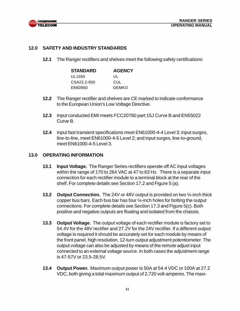
12.0 SAFETY AND INDUSTRY STANDARDS
12.1 The Ranger rectifiers and shelves meet the following safety certifications:
STANDARD AGENCYUL1950 ULCSA22.2-950 CULEN60950 DEMKO
12.2 The Ranger rectifier and shelves are CE marked to indicate conformanceto the European Union’s Low Voltage Directive.
12.3 Input conducted EMI meets FCC20780 part 15J Curve B and EN55022Curve B.
12.4 Input fast transient specifications meet EN61000-4-4 Level 3; input surges,line-to-line, meet EN61000-4-5 Level 2; and input surges, line-to-ground,meet EN61000-4-5 Level 3.
13.0 OPERATING INFORMATION
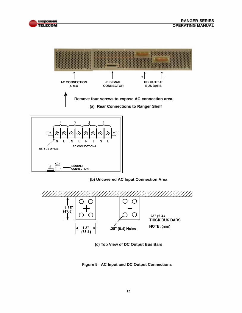
13.1 Input Voltage. The Ranger Series rectifiers operate off AC input voltageswithin the range of 170 to 264 VAC at 47 to 63 Hz. There is a separate inputconnection for each rectifier module to a terminal block at the rear of theshelf. For complete details see Section 17.2 and Figure 5 (a).
13.2 Output Connection. The 24V or 48V output is provided on two ¼-inch thickcopper bus bars. Each bus bar has four ¼-inch holes for bolting the outputconnections. For complete details see Section 17.3 and Figure 5(c). Bothpositive and negative outputs are floating and isolated from the chassis.
13.3 Output Voltage. The output voltage of each rectifier module is factory set to54.4V for the 48V rectifier and 27.2V for the 24V rectifier. If a different outputvoltage is required it should be accurately set for each module by means ofthe front panel, high resolution, 12-turn output adjustment potentiometer. Theoutput voltage can also be adjusted by means of the remote adjust inputconnected to an external voltage source. In both cases the adjustment rangeis 47-57V or 23.5-28.5V.
13.4 Output Power. Maximum output power is 50A at 54.4 VDC or 100A at 27.2VDC, both giving a total maximum output of 2,720 volt-amperes. The maxi-
12
RANGER SERIESOPERATING MANUAL
Figure 5 . AC Input and DC Output Connections
(b) Uncovered AC Input Connection Area
(c) Top View of DC Output Bus Bars
(a) Rear Connections to Ranger Shelf
AC CONNECTIONAREA
J1 SIGNALCONNECTOR
DC OUTPUTBUS BARS
+ -
Remove four screws to expose AC connection area.
13
RANGER SERIESOPERATING MANUAL
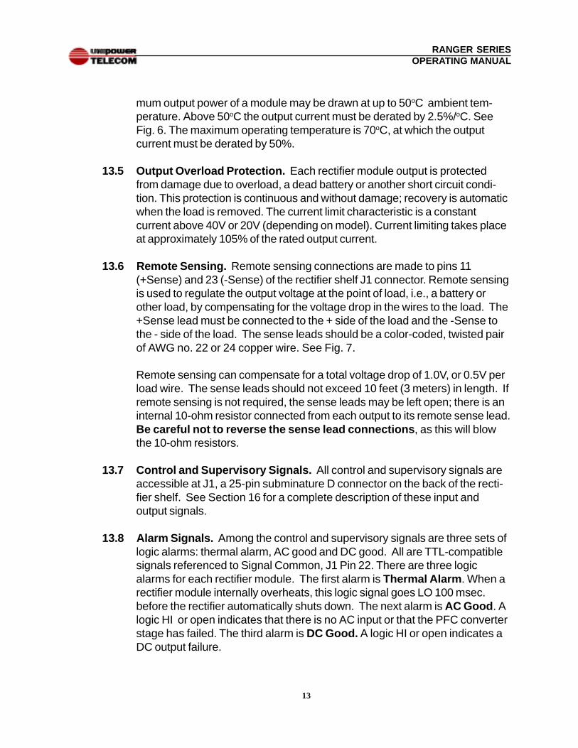
mum output power of a module may be drawn at up to 50oC ambient tem-perature. Above 50oC the output current must be derated by 2.5%/oC. SeeFig. 6. The maximum operating temperature is 70oC, at which the outputcurrent must be derated by 50%.
13.5 Output Overload Protection. Each rectifier module output is protectedfrom damage due to overload, a dead battery or another short circuit condi-tion. This protection is continuous and without damage; recovery is automaticwhen the load is removed. The current limit characteristic is a constantcurrent above 40V or 20V (depending on model). Current limiting takes placeat approximately 105% of the rated output current.
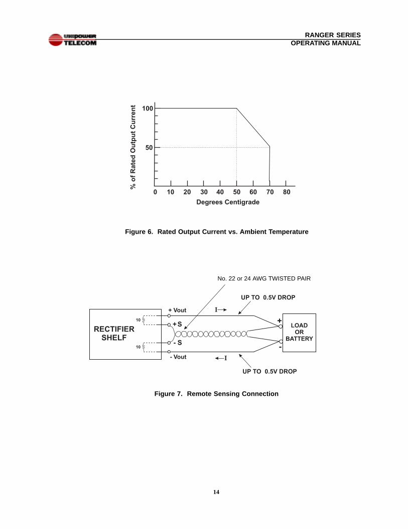
13.6 Remote Sensing. Remote sensing connections are made to pins 11(+Sense) and 23 (-Sense) of the rectifier shelf J1 connector. Remote sensingis used to regulate the output voltage at the point of load, i.e., a battery orother load, by compensating for the voltage drop in the wires to the load. The+Sense lead must be connected to the + side of the load and the -Sense tothe - side of the load. The sense leads should be a color-coded, twisted pairof AWG no. 22 or 24 copper wire. See Fig. 7.
Remote sensing can compensate for a total voltage drop of 1.0V, or 0.5V perload wire. The sense leads should not exceed 10 feet (3 meters) in length. Ifremote sensing is not required, the sense leads may be left open; there is aninternal 10-ohm resistor connected from each output to its remote sense lead.Be careful not to reverse the sense lead connections , as this will blowthe 10-ohm resistors.
13.7 Control and Supervisory Signals. All control and supervisory signals areaccessible at J1, a 25-pin subminature D connector on the back of the recti-fier shelf. See Section 16 for a complete description of these input andoutput signals.
13.8 Alarm Signals. Among the control and supervisory signals are three sets oflogic alarms: thermal alarm, AC good and DC good. All are TTL-compatiblesignals referenced to Signal Common, J1 Pin 22. There are three logicalarms for each rectifier module. The first alarm is Thermal Alarm . When arectifier module internally overheats, this logic signal goes LO 100 msec.before the rectifier automatically shuts down. The next alarm is AC Good . Alogic HI or open indicates that there is no AC input or that the PFC converterstage has failed. The third alarm is DC Good. A logic HI or open indicates aDC output failure.
14
RANGER SERIESOPERATING MANUAL
Figure 6. Rated Output Current vs. Ambient Temperature
Figure 7. Remote Sensing Connection
No. 22 or 24 AWG TWISTED PAIR
15
RANGER SERIESOPERATING MANUAL
14.0 PARALLEL OPERATION
The rectifier modules in the shelf are all connected in the parallel, current sharingmode by means of a single-wire current share connection among them. A shelf canbe operated in either an N+1 redundant mode or non-redundant mode.
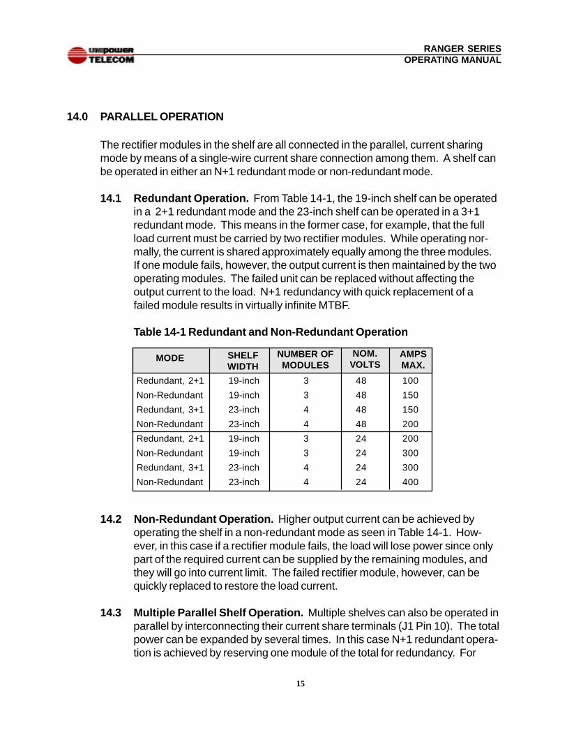
14.1 Redundant Operation. From Table 14-1, the 19-inch shelf can be operatedin a 2+1 redundant mode and the 23-inch shelf can be operated in a 3+1redundant mode. This means in the former case, for example, that the fullload current must be carried by two rectifier modules. While operating nor-mally, the current is shared approximately equally among the three modules.If one module fails, however, the output current is then maintained by the twooperating modules. The failed unit can be replaced without affecting theoutput current to the load. N+1 redundancy with quick replacement of afailed module results in virtually infinite MTBF.
Table 14-1 Redundant and Non-Redundant Operation
14.2 Non-Redundant Operation. Higher output current can be achieved byoperating the shelf in a non-redundant mode as seen in Table 14-1. How-ever, in this case if a rectifier module fails, the load will lose power since onlypart of the required current can be supplied by the remaining modules, andthey will go into current limit. The failed rectifier module, however, can bequickly replaced to restore the load current.
14.3 Multiple Parallel Shelf Operation. Multiple shelves can also be operated inparallel by interconnecting their current share terminals (J1 Pin 10). The totalpower can be expanded by several times. In this case N+1 redundant opera-tion is achieved by reserving one module of the total for redundancy. For
Redundant, 2+1 19-inch 3 48 100
Non-Redundant 19-inch 3 48 150
Redundant, 3+1 23-inch 4 48 150
Non-Redundant 23-inch 4 48 200
Redundant, 2+1 19-inch 3 24 200
Non-Redundant 19-inch 3 24 300
Redundant, 3+1 23-inch 4 24 300
Non-Redundant 23-inch 4 24 400
MODE SHELFWIDTH
NOM.VOLTS
NUMBER OFMODULES
AMPSMAX.
16
RANGER SERIESOPERATING MANUAL
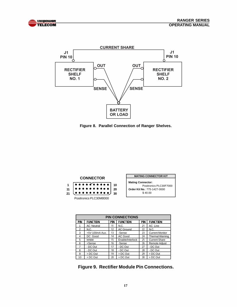
example, if two full 19-inch shelves are employed with a total of six rectifiermodules, then for 5+1 redundancy the full load must be able to be carried bythe output of five modules. In such applications each set of remote sensewires must be separately connected to the battery or point of load. SeeFigure 8 for a simplified illustration of two rectifier shelves connected inparallel.
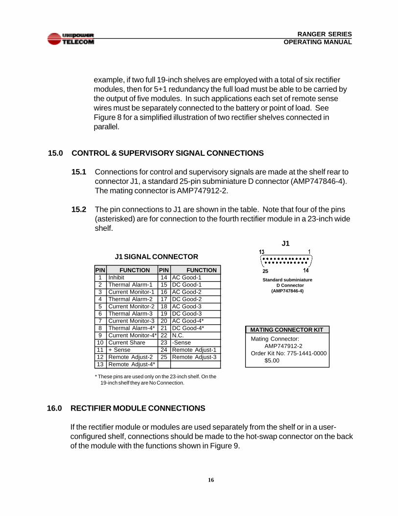
15.0 CONTROL & SUPERVISORY SIGNAL CONNECTIONS
15.1 Connections for control and supervisory signals are made at the shelf rear toconnector J1, a standard 25-pin subminiature D connector (AMP747846-4).The mating connector is AMP747912-2.
15.2 The pin connections to J1 are shown in the table. Note that four of the pins(asterisked) are for connection to the fourth rectifier module in a 23-inch wideshelf.
Standard subminiatureD Connector
(AMP747846-4)
J1 SIGNAL CONNECTOR
PIN FUNCTION1 Inhibit2 Thermal Alarm-13 Current Monitor-14 Thermal Alarm-25 Current Monitor-26 Thermal Alarm-37 Current Monitor-38 Thermal Alarm-4*9 Current Monitor-4*
10 Current Share11 + Sense12 Remote Adjust-213 Remote Adjust-4*
PIN FUNCTION14 AC Good-115 DC Good-116 AC Good-217 DC Good-218 AC Good-319 DC Good-320 AC Good-4*21 DC Good-4*22 N.C.23 -Sense24 Remote Adjust-125 Remote Adjust-3
* These pins are used only on the 23-inch shelf. On the19-inch shelf they are No Connection.
J1
MATING CONNECTOR KIT
Mating Connector:AMP747912-2
Order Kit No: 775-1441-0000$5.00
16.0 RECTIFIER MODULE CONNECTIONS
If the rectifier module or modules are used separately from the shelf or in a user-configured shelf, connections should be made to the hot-swap connector on the backof the module with the functions shown in Figure 9.
25
17
RANGER SERIESOPERATING MANUAL
Figure 8. Parallel Connection of Ranger Shelves.
PIN11121314151617181920
FUNCTIONN.C.AC Ground-SenseAC GoodEnable/Interlock-Sense- DC Out- DC Out+ DC Out+ DC Out
PIN CONNECTIONSPIN123456789
10
FUNCTIONAC NeutralN.C.+5V 100mA Aux.DC GoodInhibit+Sense- DC Out- DC Out+ DC Out+ DC Out
PIN21222324252627282930
FUNCTIONAC LineN.C.Current MonitorThermal WarningCurrent ShareRemote Adjust- DC Out- DC Out+ DC Out+ DC Out
MATING CONNECTOR KIT
Mating Connector:Positronics PLC30F7000
Order Kit No .: 775-1427-0000$ 40.00
CONNECTOR
Figure 9. Rectifier Module Pin Connections.
102030
11121
Positronics PLC30M8000
18
RANGER SERIESOPERATING MANUAL
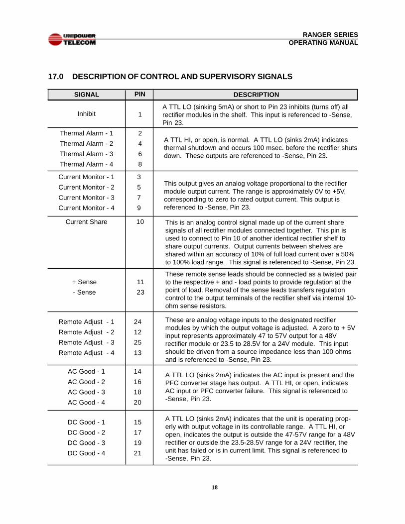
A TTL LO (sinking 5mA) or short to Pin 23 inhibits (turns off) allrectifier modules in the shelf. This input is referenced to -Sense,Pin 23.
Inhibit
Thermal Alarm - 1
Thermal Alarm - 2
Thermal Alarm - 3
Thermal Alarm - 4
SIGNAL PIN
1
2
4
6
8
DESCRIPTION
17.0 DESCRIPTION OF CONTROL AND SUPERVISORY SIGNALS
A TTL HI, or open, is normal. A TTL LO (sinks 2mA) indicatesthermal shutdown and occurs 100 msec. before the rectifier shutsdown. These outputs are referenced to -Sense, Pin 23.
Current Share
Remote Adjust - 1
Remote Adjust - 2
Remote Adjust - 3
Remote Adjust - 4
AC Good - 1
AC Good - 2
AC Good - 3
AC Good - 4
10
24
12
25
13
14
16
18
20
DC Good - 1
DC Good - 2
DC Good - 3
DC Good - 4
15
17
19
21
11
23
+ Sense
- Sense
This is an analog control signal made up of the current sharesignals of all rectifier modules connected together. This pin isused to connect to Pin 10 of another identical rectifier shelf toshare output currents. Output currents between shelves areshared within an accuracy of 10% of full load current over a 50%to 100% load range. This signal is referenced to -Sense, Pin 23.
These remote sense leads should be connected as a twisted pairto the respective + and - load points to provide regulation at thepoint of load. Removal of the sense leads transfers regulationcontrol to the output terminals of the rectifier shelf via internal 10-ohm sense resistors.
These are analog voltage inputs to the designated rectifiermodules by which the output voltage is adjusted. A zero to + 5Vinput represents approximately 47 to 57V output for a 48Vrectifier module or 23.5 to 28.5V for a 24V module. This inputshould be driven from a source impedance less than 100 ohmsand is referenced to -Sense, Pin 23.
A TTL LO (sinks 2mA) indicates the AC input is present and thePFC converter stage has output. A TTL HI, or open, indicatesAC input or PFC converter failure. This signal is referenced to-Sense, Pin 23.
A TTL LO (sinks 2mA) indicates that the unit is operating prop-erly with output voltage in its controllable range. A TTL HI, oropen, indicates the output is outside the 47-57V range for a 48Vrectifier or outside the 23.5-28.5V range for a 24V rectifier, theunit has failed or is in current limit. This signal is referenced to-Sense, Pin 23.
Current Monitor - 1
Current Monitor - 2
Current Monitor - 3
Current Monitor - 4
3
5
7
9
This output gives an analog voltage proportional to the rectifiermodule output current. The range is approximately 0V to +5V,corresponding to zero to rated output current. This output isreferenced to -Sense, Pin 23.
19
RANGER SERIESOPERATING MANUAL
18.0 INSTALLATION
18.1 Mounting. The Ranger Series rectifier shelves are mounted in a rack bymeans of mounting brackets on each side of the shelves. One set of stan-dard brackets is supplied with each shelf. There are seven different bracketpositions on the side of the shelf, from front position to 6 inches from thefront. When mounting, the shelf should first be securely mounted to therack, then the rectifier modules inserted into the shelf.The rectifier modulesshould be secured by tightening the two captive panel screws on eachmodule.
18.2 AC Input Connections . The AC input connections to the rectifier shelf areshown in Figure 5(b). As shown, there are separate connections for eachrectifier module on the eight-terminal strip. All connections must be AC three-wire with the safety ground wires going to the ground connection terminal atthe bottom of the chassis. The connections are labeled by rectifier modulenumber.
18.3 DC Output Connections. The DC output connections are shown in Figure5(a) and (c). The positive and negative output connections are made to thecopper bus bars as shown. The upper left bar is positive and the lower rightone negative. Each bus bar has four ¼ - inch holes. Connection to the busbars should be made by means of four bolts with nuts. The output wires orbus bars should be sized in accordance with the load current and length ofconductor. Table 18-1 shows minimum permissible copper wire sizes up to50oC ambient temperature.
18.4 Contact Resistance. Connection to the bus bars should be clean and tightto minimize contact resistance.
18.5 Control and Supervisory Signal Connections. These connections aremade to J1, a subminiature D 25-pin connector (AMP747846-4) by means ofthe mating connector. Details for these connections are given in Section 15.
20
RANGER SERIESOPERATING MANUAL
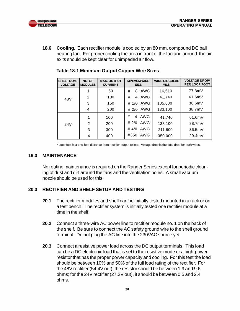
18.6 Cooling. Each rectifier module is cooled by an 80 mm, compound DC ballbearing fan. For proper cooling the area in front of the fan and around the airexits should be kept clear for unimpeded air flow.
Table 18-1 Minimum Output Copper Wire Sizes
* Loop foot is a one-foot distance from rectifier output to load. Voltage drop is the total drop for both wires.
19.0 MAINTENANCE
No routine maintenance is required on the Ranger Series except for periodic clean-ing of dust and dirt around the fans and the ventilation holes. A small vacuumnozzle should be used for this.
20.0 RECTIFIER AND SHELF SETUP AND TESTING
20.1 The rectifier modules and shelf can be initially tested mounted in a rack or ona test bench. The rectifier system is initially tested one rectifier module at atime in the shelf.
20.2 Connect a three-wire AC power line to rectifier module no. 1 on the back ofthe shelf. Be sure to connect the AC safety ground wire to the shelf groundterminal. Do not plug the AC line into the 230VAC source yet.
20.3 Connect a resistive power load across the DC output terminals. This loadcan be a DC electronic load that is set to the resistive mode or a high-powerresistor that has the proper power capacity and cooling. For this test the loadshould be between 10% and 50% of the full load rating of the rectifier. Forthe 48V rectifier (54.4V out), the resistor should be between 1.9 and 9.6ohms; for the 24V rectifier (27.2V out), it should be between 0.5 and 2.4ohms.
48V
SHELF NOM.VOLTAGE
NO. OFMODULES
1
2
3
4
50
100
150
200
MAX. OUTPUTCURRENT
MINIMUM WIRESIZE
# 8 AWG
# 4 AWG
# 1/0 AWG
# 2/0 AWG
WIRE CIRCULARMILS
16,510
41,740
105,600
133,100
VOLTAGE DROP*PER LOOP FOOT
77.8mV
61.6mV
36.6mV
38.7mV
24V
1
2
3
4
100
200
300
400
# 4 AWG
# 2/0 AWG
# 4/0 AWG
# 350 AWG
41,740
133,100
211,600
350,000
61.6mV
38.7mV
36.5mV
29.4mV
21
RANGER SERIESOPERATING MANUAL
20.4 Connect a color-coded, twisted pair (no. 22 or 24 AWG) from the remotesense pins to the load. The +Sense lead (J1 Pin 11) must go to the positiveside of the load and the - Sense lead (J1 Pin 23) must go to the negative sideof the load. Connect a wire from Remote Enable (J1 Pin 1) to SignalCommon (Pin 22). This connection must be made for the module tooperate.
20.5 Insert one of the rectifier modules into slot 1 of the shelf (leftmost slot.) Plugthe AC power line into a 230VAC source and measure the voltage across theload at the remote sense points with a digital voltmeter. The voltage shouldbe approximately 54.4V for a 48V rectifier or 27.2V for a 24V rectifier. If adifferent output voltage is desired, it should be set by means of the voltageadjustment potentiometer on the front panel.
20.6 Checking the Front Panel LEDs . The AC Good and DC Good LEDsshould both be green.
20.7 Checking the Remote Enable Input. Next, disconnect the Remote Enablewire going from J1 Pin 1 to Pin 22. The rectifier output should turn off, givingzero volts across the load. The DC Good LED should go off.
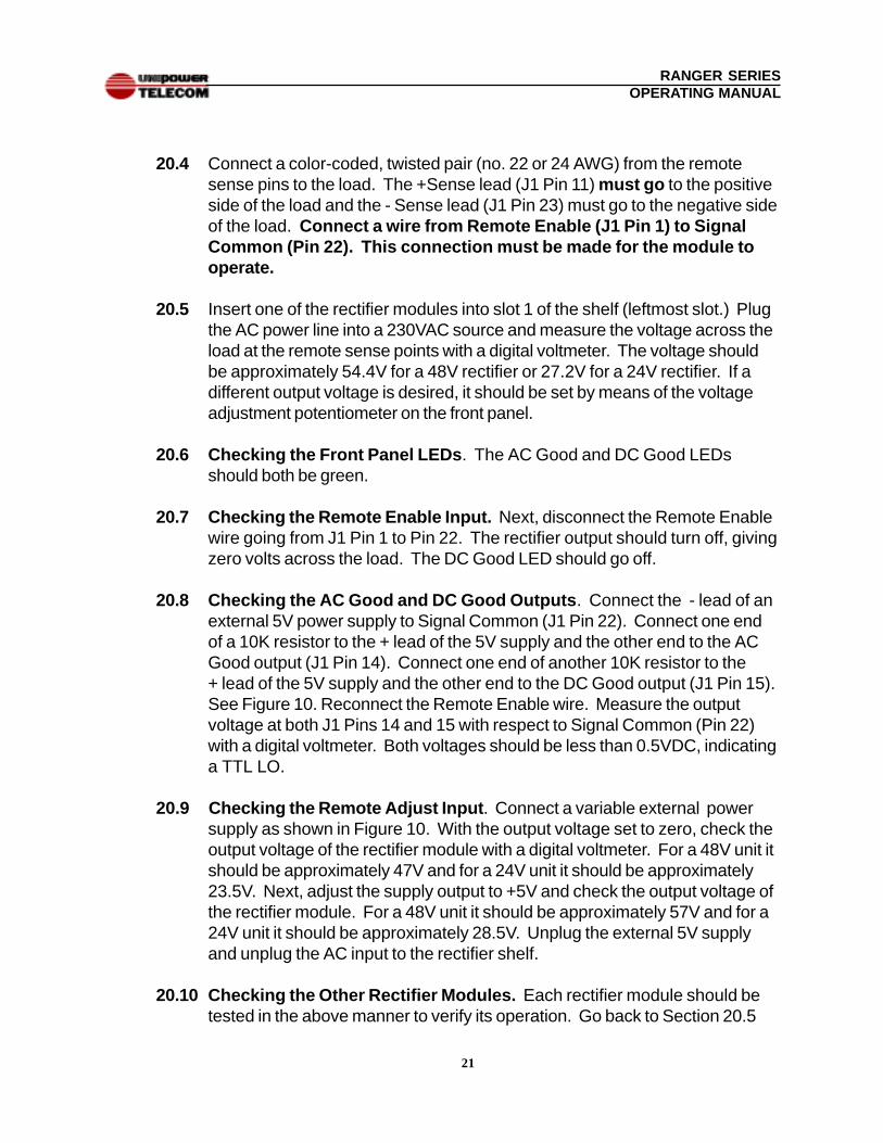
20.8 Checking the AC Good and DC Good Outputs . Connect the - lead of anexternal 5V power supply to Signal Common (J1 Pin 22). Connect one endof a 10K resistor to the + lead of the 5V supply and the other end to the ACGood output (J1 Pin 14). Connect one end of another 10K resistor to the+ lead of the 5V supply and the other end to the DC Good output (J1 Pin 15).See Figure 10. Reconnect the Remote Enable wire. Measure the outputvoltage at both J1 Pins 14 and 15 with respect to Signal Common (Pin 22)with a digital voltmeter. Both voltages should be less than 0.5VDC, indicatinga TTL LO.
20.9 Checking the Remote Adjust Input . Connect a variable external powersupply as shown in Figure 10. With the output voltage set to zero, check theoutput voltage of the rectifier module with a digital voltmeter. For a 48V unit itshould be approximately 47V and for a 24V unit it should be approximately23.5V. Next, adjust the supply output to +5V and check the output voltage ofthe rectifier module. For a 48V unit it should be approximately 57V and for a24V unit it should be approximately 28.5V. Unplug the external 5V supplyand unplug the AC input to the rectifier shelf.
20.10 Checking the Other Rectifier Modules. Each rectifier module should betested in the above manner to verify its operation. Go back to Section 20.5
22
RANGER SERIESOPERATING MANUAL
Figure 10. Checking AC Good and DC Good Outputs
Figure 11. Checking Remote Adjust Input
23
23
RANGER SERIESOPERATING MANUAL
and proceed through the tests one by one until all rectifier modules have been
verified.
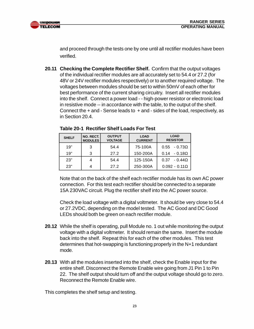
20.11 Checking the Complete Rectifier Shelf. Confirm that the output voltagesof the individual rectifier modules are all accurately set to 54.4 or 27.2 (for48V or 24V rectifier modules respectively) or to another required voltage. Thevoltages between modules should be set to within 50mV of each other forbest performance of the current sharing circuitry. Insert all rectifier modulesinto the shelf. Connect a power load - - high-power resistor or electronic loadin resistive mode -- in accordance with the table, to the output of the shelf.Connect the + and - Sense leads to + and - sides of the load, respectively, asin Section 20.4.
Table 20-1 Rectifier Shelf Loads For Test
Note that on the back of the shelf each rectifier module has its own AC powerconnection. For this test each rectifier should be connected to a separate15A 230VAC circuit. Plug the rectifier shelf into the AC power source.
Check the load voltage with a digital voltmeter. It should be very close to 54.4or 27.2VDC, depending on the model tested. The AC Good and DC GoodLEDs should both be green on each rectifier module.
20.12 While the shelf is operating, pull Module no. 1 out while monitoring the outputvoltage with a digital voltmeter. It should remain the same. Insert the moduleback into the shelf. Repeat this for each of the other modules. This testdetermines that hot-swapping is functioning properly in the N+1 redundantmode.
20.13 With all the modules inserted into the shelf, check the Enable input for theentire shelf. Disconnect the Remote Enable wire going from J1 Pin 1 to Pin22. The shelf output should turn off and the output voltage should go to zero.Reconnect the Remote Enable wire.
This completes the shelf setup and testing.
19”
19”
23”
23”
SHELF NO. RECT.MODULES
3
3
4
4
54.4
27.2
54.4
27.2
OUTPUTVOLTAGE
LOADCURRENT
75-100A
150-200A
125-150A
250-300A
LOADRESISTOR
0.55 - 0.73Ω0.14 - 0.18Ω0.37 - 0.44Ω0.092 - 0.11Ω