Embed Size (px)
Citation preview

Operating Manual
PFB-2500
Portable Filtration Module
Part Number FM03
Master Contract No. 215873
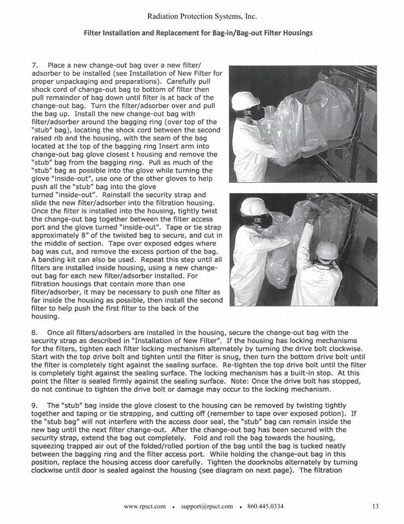
Certificate No. 2449861
Class 3812-81– Fans and Blowers
Class 3812-01– Fans and Blowers
Radiation Protection Systems, Inc.
860.445.0334 ● 888.637.7779
www.rpsct.com ● [email protected]
Radiation Protection Systems, Inc.
www.rpsct.com ● [email protected] ● 860.445.0334 2
Operating Manual
PFB-2500
Issue 8-1-2011
TABLE OF CONTENTS
I. DESCRIPTION…………………………………………………………………………...3
II. COMPONENT SPECIFICATIONS………………………………………….……….….3
III. ARRANGEMENT DRAWING……………………………………………….…………..4
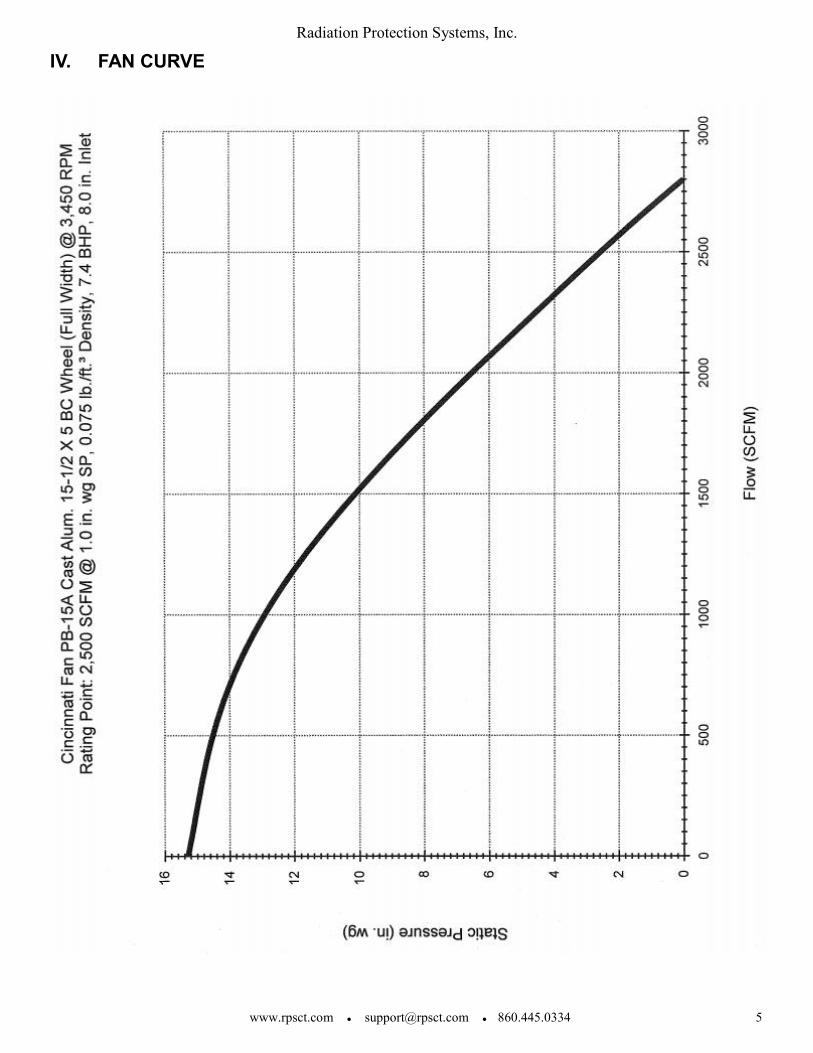
IV. FAN CURVE………………………………………………………………………….......5
V. OPERATING INSTRUCTIONS…………………………………………………………6
VI. FILTER CHANGE………………………………………………………………………...8
VII. TROUBLESHOOTING GUIDE……………………………………………………..…16
VIII. PREVENTIVE MAINTENANCE……………………………………………………....16
IX. SPARE PARTS MATRIX……………………………………………………………....17
X. ELECTRICAL WIRING DIAGRAM……………………………………………….…...17
XIII. WARRANTY……………………………………………………………………………..18
Radiation Protection Systems, Inc.
www.rpsct.com ● [email protected] ● 860.445.0334 3
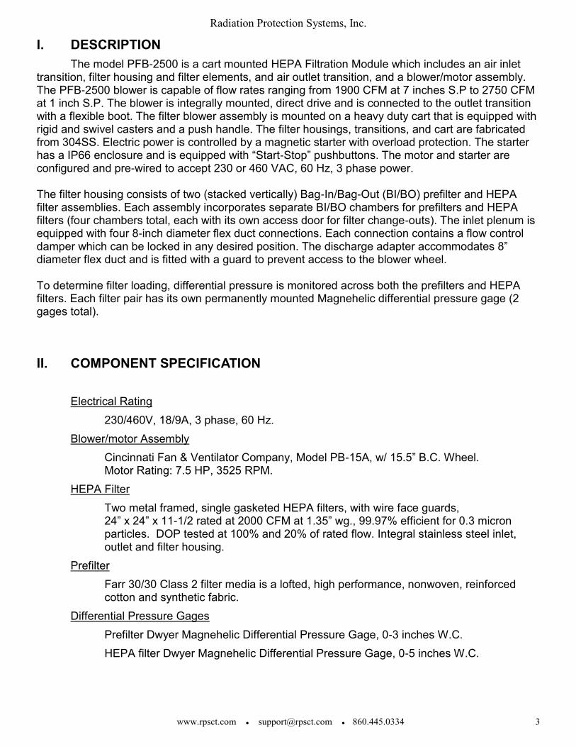
I. DESCRIPTION
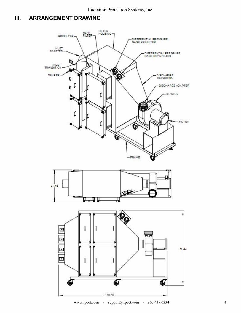
The model PFB-2500 is a cart mounted HEPA Filtration Module which includes an air inlet transition, filter housing and filter elements, and air outlet transition, and a blower/motor assembly. The PFB-2500 blower is capable of flow rates ranging from 1900 CFM at 7 inches S.P to 2750 CFM at 1 inch S.P. The blower is integrally mounted, direct drive and is connected to the outlet transition with a flexible boot. The filter blower assembly is mounted on a heavy duty cart that is equipped with rigid and swivel casters and a push handle. The filter housings, transitions, and cart are fabricated from 304SS. Electric power is controlled by a magnetic starter with overload protection. The starter has a IP66 enclosure and is equipped with “Start-Stop” pushbuttons. The motor and starter are configured and pre-wired to accept 230 or 460 VAC, 60 Hz, 3 phase power. The filter housing consists of two (stacked vertically) Bag-In/Bag-Out (BI/BO) prefilter and HEPA filter assemblies. Each assembly incorporates separate BI/BO chambers for prefilters and HEPA filters (four chambers total, each with its own access door for filter change-outs). The inlet plenum is equipped with four 8-inch diameter flex duct connections. Each connection contains a flow control damper which can be locked in any desired position. The discharge adapter accommodates 8” diameter flex duct and is fitted with a guard to prevent access to the blower wheel. To determine filter loading, differential pressure is monitored across both the prefilters and HEPA filters. Each filter pair has its own permanently mounted Magnehelic differential pressure gage (2 gages total).
II. COMPONENT SPECIFICATION
Electrical Rating
230/460V, 18/9A, 3 phase, 60 Hz.
Blower/motor Assembly
Cincinnati Fan & Ventilator Company, Model PB-15A, w/ 15.5” B.C. Wheel. Motor Rating: 7.5 HP, 3525 RPM.
HEPA Filter
Two metal framed, single gasketed HEPA filters, with wire face guards, 24” x 24” x 11-1/2 rated at 2000 CFM at 1.35” wg., 99.97% efficient for 0.3 micron particles. DOP tested at 100% and 20% of rated flow. Integral stainless steel inlet, outlet and filter housing.
Prefilter
Farr 30/30 Class 2 filter media is a lofted, high performance, nonwoven, reinforced cotton and synthetic fabric.
Differential Pressure Gages
Prefilter Dwyer Magnehelic Differential Pressure Gage, 0-3 inches W.C.
HEPA filter Dwyer Magnehelic Differential Pressure Gage, 0-5 inches W.C.
Radiation Protection Systems, Inc.
www.rpsct.com ● [email protected] ● 860.445.0334 4
III. ARRANGEMENT DRAWING
Radiation Protection Systems, Inc.
www.rpsct.com ● [email protected] ● 860.445.0334 6
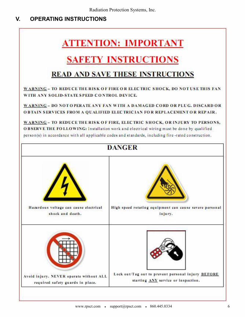
V. OPERATING INSTRUCTIONS
Radiation Protection Systems, Inc.
www.rpsct.com ● [email protected] ● 860.445.0334 7
A. Prerequisites
1. Inspect all components/hardware for damage. Ensure the filters have been installed.
2. Check differential pressure gage for zero set point. Zero as necessary.
3. Ensure blower motor controller is in “OFF” position. Check all electrical connections
and cables for damage.
B. Cautions
1. Perform frequent gamma surveys of filter housing, especially immediately following
initial system start-up. Radiation dose rates may increase rapidly.
2. Where bends in flexible ducting runs are required to suit working configurations, avoid
sharp bends. The number of bends should be kept to a minimum to minimize pressure
drops through the system.
C. Operation
1. Arrange unit in the configuration desired for ventilation supply.
2. Energize the blower and verify correct motor rotation. If motor is rotating backwards,
immediately de-energize and correct phase rotation before re-energizing.
3. Adjust duct dampers as necessary to provide ventilation requirements.
4. Note the initial reading on the differential pressure gages once the desired system flow
has been achieved. This information will be used to determine when filter changing is
required.
Radiation Protection Systems, Inc.
www.rpsct.com ● [email protected] ● 860.445.0334 8
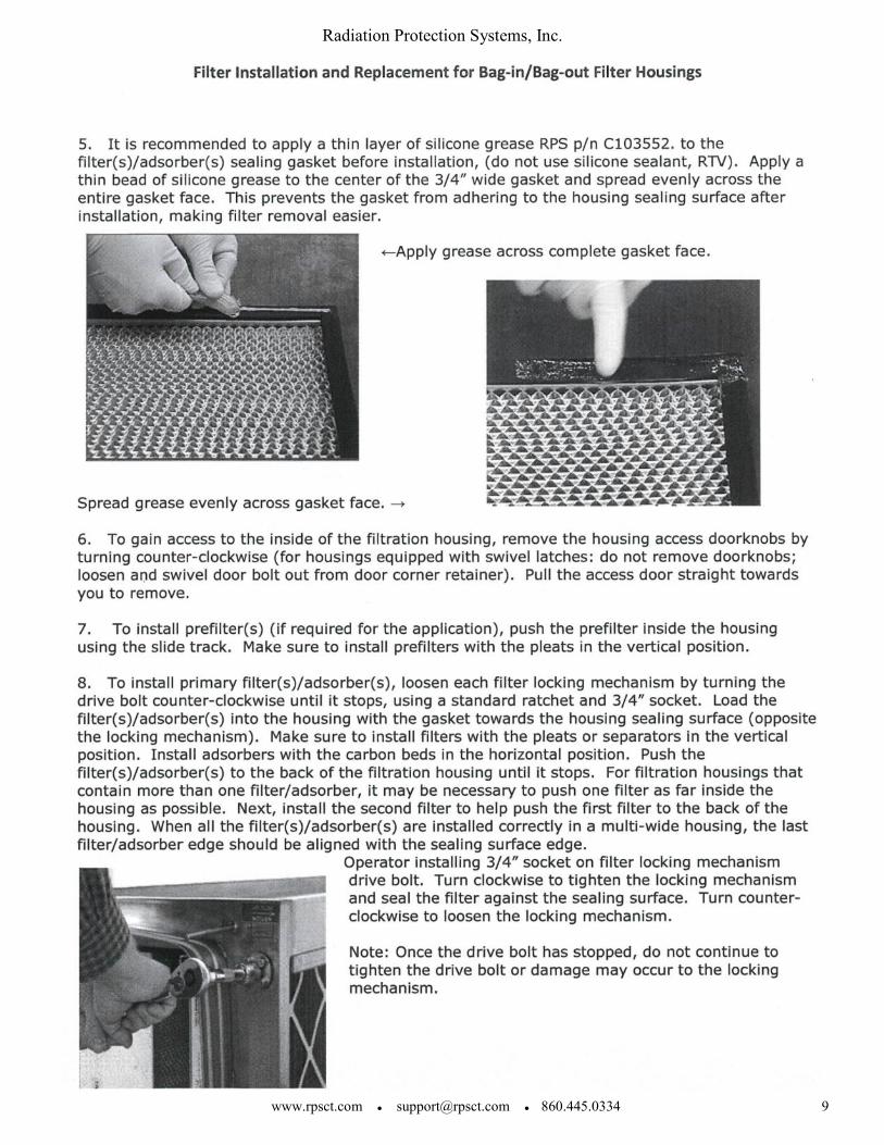
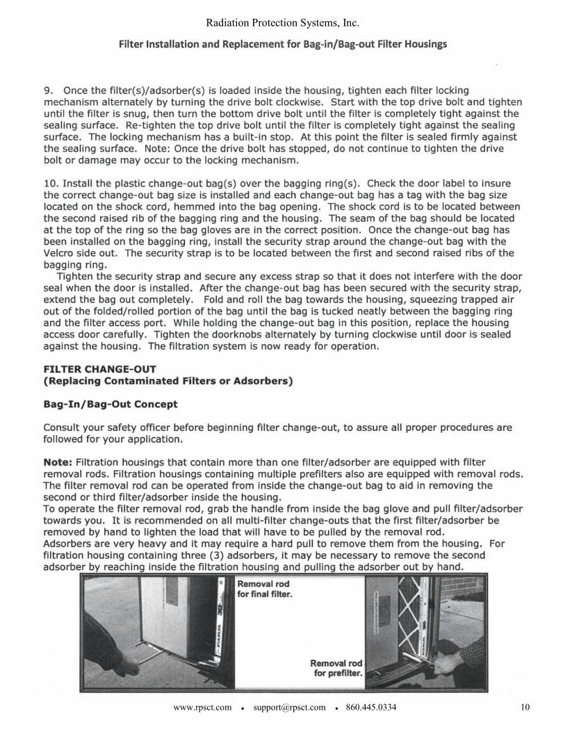
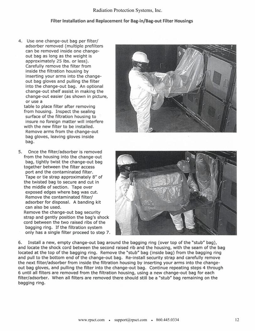
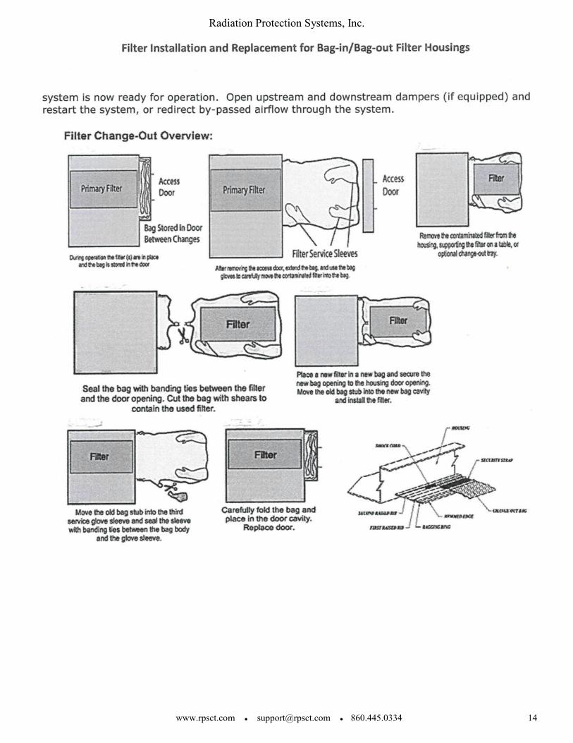
VI. FILTER CHANGE-OUT Filter change requirements are generally dictated by three conditions: radiation levels within the filter housing, ventilation flow requirements reduced by filter loading, or excessive differential pressure. Site radiological procedures will govern when radiological conditions warrant filter change-out. As the filters load with dirt, the system flow rate will begin to fall. Depending upon the application, the flow rate may fall below acceptable levels before the filters become fully loaded with dirt. In this case, the actual flow rate will dictate when the filters are changed. High differential pressure (DP) across the prefilters or HEPA filters indicate that the filters are dirty. Filter change-out should be performed when (or before) the DP across the prefilters increases to approximately 2" - 3" wg pressure or the HEPA filters to approximately 4" - 5" wg pressure. The prefilter should be changed out more frequently to help preserve the HEPA filter. Applications with conditions of high amounts of dust and debris will require more frequent filter changes than low airborne dust conditions. The pre filter should not be operated above 3” wg or the HEPA filter above 5” for an extended period. NOTE: Prior to filter change-out, survey the filter assemblies to determine radiation and contamination levels. Results will indicate protective measures to be taken.
Radiation Protection Systems, Inc.
www.rpsct.com ● [email protected] ● 860.445.0334 16
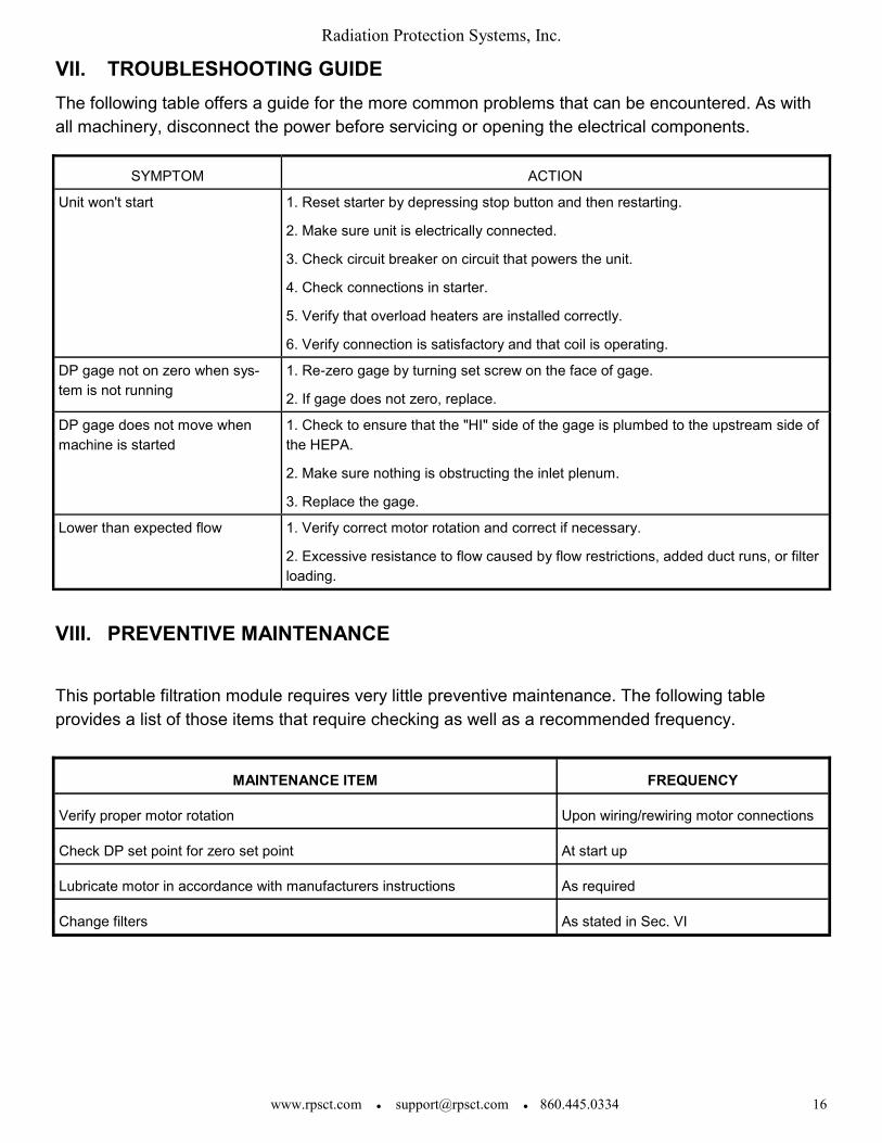
VII. TROUBLESHOOTING GUIDE
The following table offers a guide for the more common problems that can be encountered. As with
all machinery, disconnect the power before servicing or opening the electrical components.
VIII. PREVENTIVE MAINTENANCE
This portable filtration module requires very little preventive maintenance. The following table
provides a list of those items that require checking as well as a recommended frequency.
SYMPTOM ACTION
Unit won't start 1. Reset starter by depressing stop button and then restarting.
2. Make sure unit is electrically connected.
3. Check circuit breaker on circuit that powers the unit.
4. Check connections in starter.
5. Verify that overload heaters are installed correctly.
6. Verify connection is satisfactory and that coil is operating.
DP gage not on zero when sys-
tem is not running
1. Re-zero gage by turning set screw on the face of gage.
2. If gage does not zero, replace.
DP gage does not move when
machine is started
1. Check to ensure that the "HI" side of the gage is plumbed to the upstream side of
the HEPA.
2. Make sure nothing is obstructing the inlet plenum.
3. Replace the gage.
Lower than expected flow 1. Verify correct motor rotation and correct if necessary.
2. Excessive resistance to flow caused by flow restrictions, added duct runs, or filter
loading.
MAINTENANCE ITEM FREQUENCY
Verify proper motor rotation Upon wiring/rewiring motor connections
Check DP set point for zero set point At start up
Lubricate motor in accordance with manufacturers instructions As required
Change filters As stated in Sec. VI

Radiation Protection Systems, Inc.
www.rpsct.com ● [email protected] ● 860.445.0334 17
IX. SPARE PARTS MATRIX
X. ELECTRICAL WIRING DIAGRAM
Attached diagram for reference.
DESCRIPTION RPS PART NO. QTY. NOTES
PFB-2500 HEPA filter AK07 2 Spare
Prefilter AK64 2 Spare
Magnehelic Gage AR01 1 Repair
Blower assembly AL04 1 Repair
Motor BH05 1 Repair
Hose clamp, 8” CL05 1 Repair
Blower boot CM03 1 Repair
Starter C103464 1 Repair
Prefilter change out bag (Bag In/ Bag Out) AB20 2 Spare
HEPA filter change out bag (Bag In/ Bag Out) AB21 2 Spare
Radiation Protection Systems, Inc.
www.rpsct.com ● [email protected] ● 860.445.0334 18
XI. WARRANTY
Radiation Protection Systems, Inc. (RPS) warrants that the supplies delivered hereunder will
be free from defects in workmanship and materials and will conform to applicable specifications
invoked in this agreement. Subject to the limitations set forth below, RPS agrees to replace or
correct within a reasonable time frame and without expense to the Buyer any supplies not
conforming to the foregoing requirements when notified by Buyer thereof during a period of 12
months after delivery, provided that if the supplies have become radiologically contaminated, the
Buyer will perform at its own expense any decontamination which may reasonably be required by
RPS so that repair or replacement can be effected. In no event will contaminated supplies be
shipped back to RPS. All returns must be authorized by RPS prior to shipment back to RPS.
This warranty excludes consumable parts, such as filter elements, bulbs, fuses, etc. during
the warranty period.
Failure of the Buyer to properly complete all installation requirements, system test
requirements and maintenance procedures as required by RPS via technical, operational or
maintenance manuals shall release RPS from all of its obligations as herein provided.
The foregoing warranties are exclusive and in lieu of all other warranties, whether express or
implied, including any warranty of merchantability or fitness for a particular purpose. Failure of the
Buyer to promptly notify RPS of any such non-conformity shall release RPS from all of its obligations
as herein provided. Further, any repairs or alterations to the equipment by the Buyer not authorized
by RPS in advance shall release RPS from its warranty obligations. Any defects or damage
resulting from abnormal use, misuse, abuse, or normal wear and tear are not covered under this
warranty and shall be the responsibility of the Buyer. This warranty applies only to the extent that
any equipment or process furnished hereunder is in accordance with Seller's goods regularly sold
and not (a) supplied according to Buyer's design or instructions; (b) modified to meet particular
needs of Buyer; or (c) combined by Buyer with items not furnished hereunder, where such design,
instruction, modification or combination is responsible for the warranty claim. The foregoing states
the entire liability of Seller with respect to warranty.


![Ziegelei 1 Tel.: +49-[0]7433- 9933-0 D-72336 Balingen … · KERN PFB Version 2.2 02/2013 GB . PFB-BA-e-1322. 2 PFB-BA-e-1322 . KERN PFB GB Version 2.2 02/2013 Operating Manual](https://img.pdfslide.us/doc/110x75/5bac9da709d3f2b47d8bea9d/ziegelei-1-tel-49-07433-9933-0-d-72336-balingen-kern-pfb-version-22-022013.jpg)