Embed Size (px)
Citation preview
1
www.peavey.com
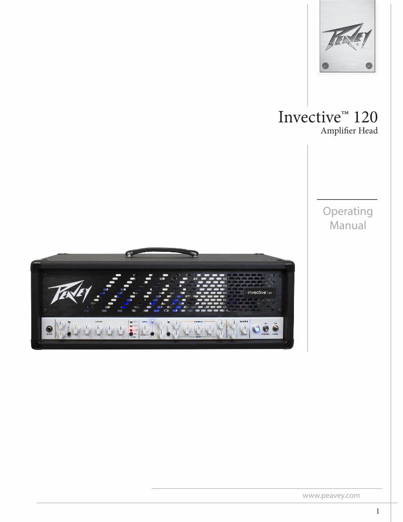
Invective™ 120Amplifier Head
OperatingManual

2
FCC/ICES Compliancy Statement
This device complies with Part 15 of the FCC rules and Industry Canada license-exempt RSS Standard(s). Operation is subject to the following two conditions: (1) this device may not cause harmful interference, and (2) this device must accept any interference received, that may cause undesired operation.
Le présent appareil est conforme aux CNR d’lndustrie Canada applicables aux appareils radio exempts de licence. L’exploitation est autorisée aux deux conditions suivantes: (1) I’appareil ne doit pas produire de brouillage, et (2) I’utilisateur de I’appareil doit accepter tout brouillage radioélectrique subi, même si le brouillage est susceptible d’en compromettre le fonctionnement. Warning: Changes or modifications to the equipment not approved by Peavey Electronics Corp. can void the user’s authority to use the equipment. Note – This equipment has been tested and found to comply with the limits for a Class B digital device, pursuant to Part 15 of the FCC Rules. These limits are designed to provide reasonable protection against harmful interference in a residential installation. This equipment generates, uses, and can radiate radio frequency energy and, if not installed and used in accordance with the instructions, may cause harmful interference to radio communications. However, there is no guarantee that interference will not occur in a particular installation. If this equipment does cause harmful interference to radio or television reception, which can be determined by turning the equipment off and on, the user is encouraged to try and correct the interference by one or more of the following measures.
• Reorient or relocate the receiving antenna. • Increase the separation between the equipment and receiver. • Connect the equipment into an outlet on a circuit different from that to which the receiver is
connected. • Consult the dealer or an experienced radio/TV technician for help.
Caution The equipment complies with FCC radiation exposure limits set forth for an uncontrolled environment.
3
The new sound of metal is here. The Invective™ 120 is the culmination of nearly three decades of refinements and tweaks to Peavey’s legendary 6505 series with an all new clean channel and gobs of peripheral features that are staples for today’s developing musical styles. Designed in close conjunction with Misha Mansoor, of Periph-ery fame, the result is a monster of an amplifier capable of accurately reproducing tons and tons of the sickest tube amp tones imaginable….past, present, and future. Three separate channels (Clean/Crunch/Lead) and two independent input boosts (one for clean, one for high gain channels) give you a sonic palette that lets your imagination run wild. There’s also a defeatable gate at the input of both gain channels designed to quickly mute the input for a more “precise” muting characteristic. Capable of 120 Watts of earth shaking power, into the all-new solid pine Invective 212 (or any standard guitar cabinet), this behemoth can blow the roof off the largest of venues or….with a twist of the Master Volume and a flip of the half power switch, keep a crowd in the small-est of clubs. Further tonal mayhem can be accomplished with outboard effects via the footswitchable Effects Loops. The included 10-button MIDI footswitch allows for switching of all peripheral functions and storage of presets. We’ve also included an internal MSDI direct analog recording/mic’d output and two auxiliary 9VDC supply jacks for quick evaluation of pedals or to power a wireless setup. The all new Peavey® Invective™ 120….a more than worthy successor to the legacy of Peavey’s high gain supremacy.
Features
• Three channels• Preamp gain boost with gain and tone controls on Clean• Preamp boost with level and tone controls on high gain channels• Input gate on high gain channels• Master Volume and Master Boost• Resonance and Presence power amp damping controls• MSDI direct out with level and tone controls• Two Switchable effects loops• Footswitch/MIDI In and MIDI Out jack• Auxiliary 9VDC supplies• 120W (rms) into 4, 8, or 16 Ohms (selectable impedance)• Half power switch• 10-button footswitch included• Full set of current-based bias test points for easy troubleshooting
ENGLISH
4
FRONT PANEL
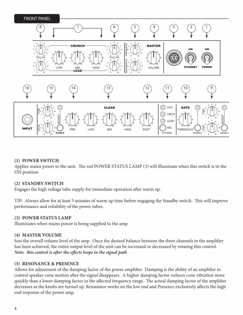
(1) POWER SWITCHApplies mains power to the unit. The red POWER STATUS LAMP (3) will illuminate when this switch is in the ON position.
(2) STANDBY SWITCHEngages the high voltage tube supply for immediate operation after warm up.
TIP: Always allow for at least 5 minutes of warm up time before engaging the Standby switch. This will improve performance and reliability of the power tubes.
(3) POWER STATUS LAMPIlluminates when mains power is being supplied to the amp.
(4) MASTER VOLUMESets the overall volume level of the amp. Once the desired balance between the three channels in the amplifier has been achieved, the entire output level of the unit can be increased or decreased by rotating this control. Note: this control is after the effects loops in the signal path
(5) RESONANCE & PRESENCEAllows for adjustment of the damping factor of the power amplifier. Damping is the ability of an amplifier to control speaker cone motion after the signal disappears. A higher damping factor reduces cone vibration more quickly than a lower damping factor in the affected frequency range. The actual damping factor of the amplifier decreases as the knobs are turned up. Resonance works on the low end and Presence exclusively affects the high end response of the power amp.
1
910111213141516
234568 7
CRUNCH
LEADPOWERSTANDBY
ONONCLEAN GATE MASTER
INPUT PRE LOW MIDSEL
CHANNEL
CLN
CRCH
LEAD
HIGH LOW MID VOLUMEHIGHENABLE ENABLEENABLE
POST THRESHOLD
BO
OS
T
DR
IVE
TON
E
ENABLE
LEV
EL
TON
E
BO
OS
T
PRE GAIN POST GAIN
RE
SO
NA
NC
EP
RE
SE
NC
E
0 10
1 9
2 8
3 7
45
6
0 10
1 9
2 8
3 7
45
6
0 10
1 9
2 8
3 7
45
6
0 10
1 9
2 8
3 7
45
6
0 10
1 9
2 8
3 7
45
6
0 10
1 9
2 8
3 7
45
6
0 10
1 9
2 8
3 7
45
6
0 10
1 9
2 8
3 7
45
6
0 10
1 9
2 8
3 7
45
6
0 10
1 9
2 8
3 7
45
6
0 10
1 9
2 8
3 7
45
6
0 10
1 9
2 8
3 7
45
6
0 10
1 9
2 8
3 7
45
6
0 10
1 9
2 8
3 7
45
6
0 10
1 9
2 8
3 7
45
6
0 10
1 9
2 8
3 7
45
6
0 10
1 9
2 8
3 7
45
6
0 10
1 9
2 8
3 7
45
6
0 10
1 9
2 8
3 7
45
6
0 10
1 9
2 8
3 7
45
6
5
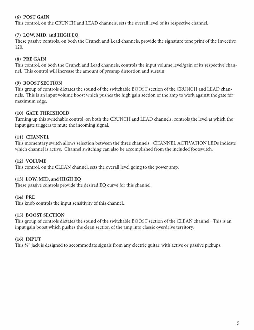
(6) POST GAINThis control, on the CRUNCH and LEAD channels, sets the overall level of its respective channel.
(7) LOW, MID, and HIGH EQThese passive controls, on both the Crunch and Lead channels, provide the signature tone print of the Invective 120.
(8) PRE GAINThis control, on both the Crunch and Lead channels, controls the input volume level/gain of its respective chan-nel. This control will increase the amount of preamp distortion and sustain.
(9) BOOST SECTION This group of controls dictates the sound of the switchable BOOST section of the CRUNCH and LEAD chan-nels. This is an input volume boost which pushes the high gain section of the amp to work against the gate for maximum edge.
(10) GATE THRESHOLD Turning up this switchable control, on both the CRUNCH and LEAD channels, controls the level at which the input gate triggers to mute the incoming signal.
(11) CHANNEL This momentary switch allows selection between the three channels. CHANNEL ACTIVATION LEDs indicate which channel is active. Channel switching can also be accomplished from the included footswitch.
(12) VOLUMEThis control, on the CLEAN channel, sets the overall level going to the power amp.
(13) LOW, MID, and HIGH EQThese passive controls provide the desired EQ curve for this channel.
(14) PREThis knob controls the input sensitivity of this channel.
(15) BOOST SECTION This group of controls dictates the sound of the switchable BOOST section of the CLEAN channel. This is an input gain boost which pushes the clean section of the amp into classic overdrive territory.
(16) INPUTThis ¼” jack is designed to accommodate signals from any electric guitar, with active or passive pickups.
6
171819202122
232425262728
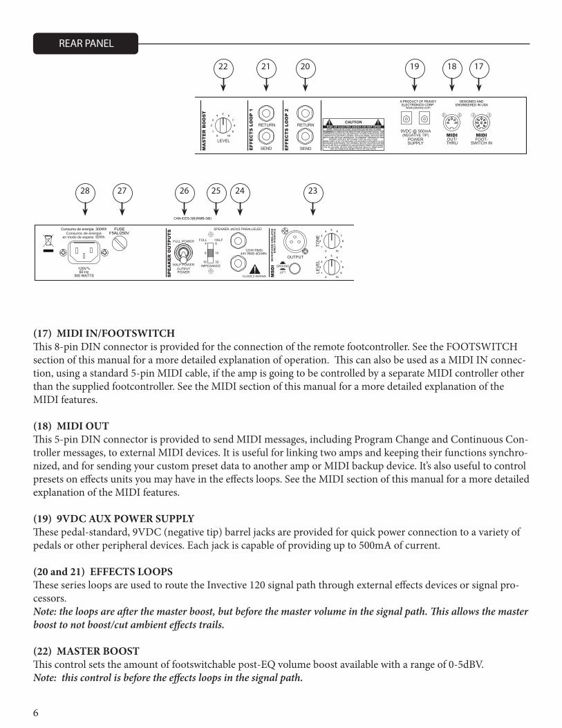
(17) MIDI IN/FOOTSWITCHThis 8-pin DIN connector is provided for the connection of the remote footcontroller. See the FOOTSWITCH section of this manual for a more detailed explanation of operation. This can also be used as a MIDI IN connec-tion, using a standard 5-pin MIDI cable, if the amp is going to be controlled by a separate MIDI controller other than the supplied footcontroller. See the MIDI section of this manual for a more detailed explanation of the MIDI features.
(18) MIDI OUTThis 5-pin DIN connector is provided to send MIDI messages, including Program Change and Continuous Con-troller messages, to external MIDI devices. It is useful for linking two amps and keeping their functions synchro-nized, and for sending your custom preset data to another amp or MIDI backup device. It’s also useful to control presets on effects units you may have in the effects loops. See the MIDI section of this manual for a more detailed explanation of the MIDI features.
(19) 9VDC AUX POWER SUPPLYThese pedal-standard, 9VDC (negative tip) barrel jacks are provided for quick power connection to a variety of pedals or other peripheral devices. Each jack is capable of providing up to 500mA of current.
(20 and 21) EFFECTS LOOPS These series loops are used to route the Invective 120 signal path through external effects devices or signal pro-cessors. Note: the loops are after the master boost, but before the master volume in the signal path. This allows the master boost to not boost/cut ambient effects trails.
(22) MASTER BOOST This control sets the amount of footswitchable post-EQ volume boost available with a range of 0-5dBV. Note: this control is before the effects loops in the signal path.
REAR PANEL
POWERSUPPLY
4
16
8
32
FUSE
60 Hz300 WATTS M
SD
I
MA
ST
ER
BO
OS
T
(NEGATIVE TIP)
RETURN
SEND
RETURN
FOOT-SWITCH IN
OUTPUT
MIC
RO
PHO
NE
SIM
ULA
TED
DIR
ECT
INTE
RFA
CE
OUT/THRULEVELIMPEDANCE
OUTPUTPOWER
FULLFULL POWER
8 16
HALF
HALF POWER
LIFT
GROUND
LEV
EL
TON
E
SP
EA
KE
R O
UT
PU
TS
MIDI MIDI
44V RMS 4 MIN.120W RMS/
SPEAKER JACKS PARALLELED
CLASS 2 WIRING
CAUTION
WARNING:APPARATUS SHOULD NOT BE EXPOSED TO RAIN OR MOISTURE AND
HAZARD, REPLACE WITH SAME TYPE 250 VOLT FUSE.
TO REDUCE THE RISK OF FIRE OR ELECTRIC SHOCK, THIS
DANS LE BUT DE REDUIRE LES RISQUES D’INCENDIE OU DEAVIS:
A LA PLUIE OU A L’HUMIDITE ET AUCUN OBJET REMPLI DE LIQUIDE,DECHARGE ELECTRIQUE, CET APPAREIL NE DOIT PAS ETRE EXPOSE
TEL QU’UN VASE, NE DOIT ETRE POSE SUR CELUI-CI. REMPLACERPAR UN FUSIBLE DE MEME TYPE ET DE 250 VOLTS.
AVIS: RISQUE DE CHOC ELECTRIQUE NE PAS OUVRIR
OBJECTS FILLED WITH LIQUIDS, SUCH AS VASES, SHOULD NOTBE PLACED ON THIS APPARATUS. TO PREVENT THE RISK OF FIRE
SEND
F5AL/250V
120V
Consumo de energia 300WhConsumo de energia
en modo de espera 92Wh
CAN-ICES-3(B)/NMB-3(B)
ENGINEERED IN USADESIGNED ANDA PRODUCT OF PEAVEY
ELECTRONICS CORP.www.peavey.com
9VDC @ 500mA
EFF
EC
TS
LO
OP
1
EFF
EC
TS
LO
OP
2
0 10
1 9
2 8
3 7
45
6
0 10
1 9
2 8
3 7
45
6
0 10
1 9
2 8
3 7
45
6
7
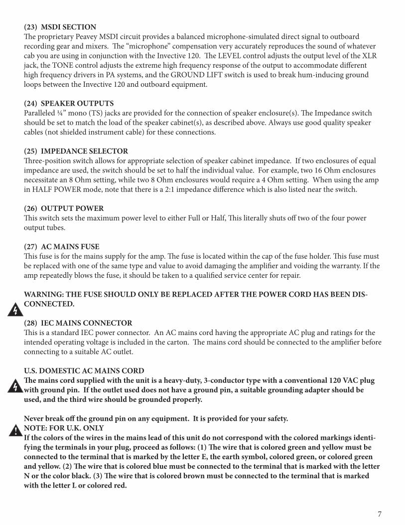
(23) MSDI SECTIONThe proprietary Peavey MSDI circuit provides a balanced microphone-simulated direct signal to outboard recording gear and mixers. The “microphone” compensation very accurately reproduces the sound of whatever cab you are using in conjunction with the Invective 120. The LEVEL control adjusts the output level of the XLR jack, the TONE control adjusts the extreme high frequency response of the output to accommodate different high frequency drivers in PA systems, and the GROUND LIFT switch is used to break hum-inducing ground loops between the Invective 120 and outboard equipment.
(24) SPEAKER OUTPUTSParalleled ¼” mono (TS) jacks are provided for the connection of speaker enclosure(s). The Impedance switch should be set to match the load of the speaker cabinet(s), as described above. Always use good quality speaker cables (not shielded instrument cable) for these connections.
(25) IMPEDANCE SELECTORThree-position switch allows for appropriate selection of speaker cabinet impedance. If two enclosures of equal impedance are used, the switch should be set to half the individual value. For example, two 16 Ohm enclosures necessitate an 8 Ohm setting, while two 8 Ohm enclosures would require a 4 Ohm setting. When using the amp in HALF POWER mode, note that there is a 2:1 impedance difference which is also listed near the switch. (26) OUTPUT POWERThis switch sets the maximum power level to either Full or Half, This literally shuts off two of the four power output tubes.
(27) AC MAINS FUSEThis fuse is for the mains supply for the amp. The fuse is located within the cap of the fuse holder. This fuse must be replaced with one of the same type and value to avoid damaging the amplifier and voiding the warranty. If the amp repeatedly blows the fuse, it should be taken to a qualified service center for repair.
WARNING: THE FUSE SHOULD ONLY BE REPLACED AFTER THE POWER CORD HAS BEEN DIS-CONNECTED.
(28) IEC MAINS CONNECTORThis is a standard IEC power connector. An AC mains cord having the appropriate AC plug and ratings for the intended operating voltage is included in the carton. The mains cord should be connected to the amplifier before connecting to a suitable AC outlet.
U.S. DOMESTIC AC MAINS CORDThe mains cord supplied with the unit is a heavy-duty, 3-conductor type with a conventional 120 VAC plug with ground pin. If the outlet used does not have a ground pin, a suitable grounding adapter should be used, and the third wire should be grounded properly.
Never break off the ground pin on any equipment. It is provided for your safety.NOTE: FOR U.K. ONLYIf the colors of the wires in the mains lead of this unit do not correspond with the colored markings identi-fying the terminals in your plug, proceed as follows: (1) The wire that is colored green and yellow must be connected to the terminal that is marked by the letter E, the earth symbol, colored green, or colored green and yellow. (2) The wire that is colored blue must be connected to the terminal that is marked with the letter N or the color black. (3) The wire that is colored brown must be connected to the terminal that is marked with the letter L or colored red.
8
TOP PANEL
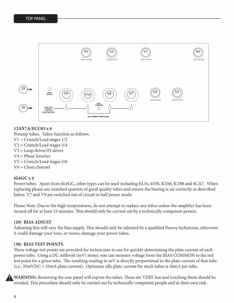
12AX7A/ECC83 x 6Preamp tubes. Tubes function as follows:V1 = Crunch/Lead stages 1/2V2 = Crunch/Lead stages 3/4V3 = Loop driver/PI driverV4 = Phase InverterV5 = Crunch/Lead stages 5/6V6 = Clean channel
6L6GC x 4Power tubes. Apart from 6L6GC, other types can be used including EL34, 6550, KT66, KT88 and 6CA7. When replacing please use matched quartets of good quality tubes and ensure the biasing is set correctly as described below. V7 and V9 are switched out of circuit in half power mode.
Please Note: Due to the high temperatures, do not attempt to replace any tubes unless the amplifier has been turned off for at least 15 minutes. This should only be carried out by a technically competent person.
(29) BIAS ADJUSTAdjusting this will vary the bias supply. This should only be adjusted by a qualified Peavey technician, otherwise it could damage your tone, or worse, damage your power tubes.
(30) BIAS TEST POINTSThese voltage test points are provided for technicians to use for quickly determining the plate current of each power tube. Using a DC millivolt (mV) meter, one can measure voltage from the BIAS COMMON to the red test point for a given tube. The resulting reading in mV is directly proportional to the plate current of that tube (i.e.: 35mVDC = 35mA plate current). Optimum idle plate current for stock tubes is 26mA per tube.
WARNING: Removing the rear panel will expose the tubes. These are VERY hot and touching them should be avoided. This procedure should only be carried out by technically competent people and at their own risk.
29
V5 V2 V1 V6
V3V4V7V8V10V9
30
9
FOOTSWITCH
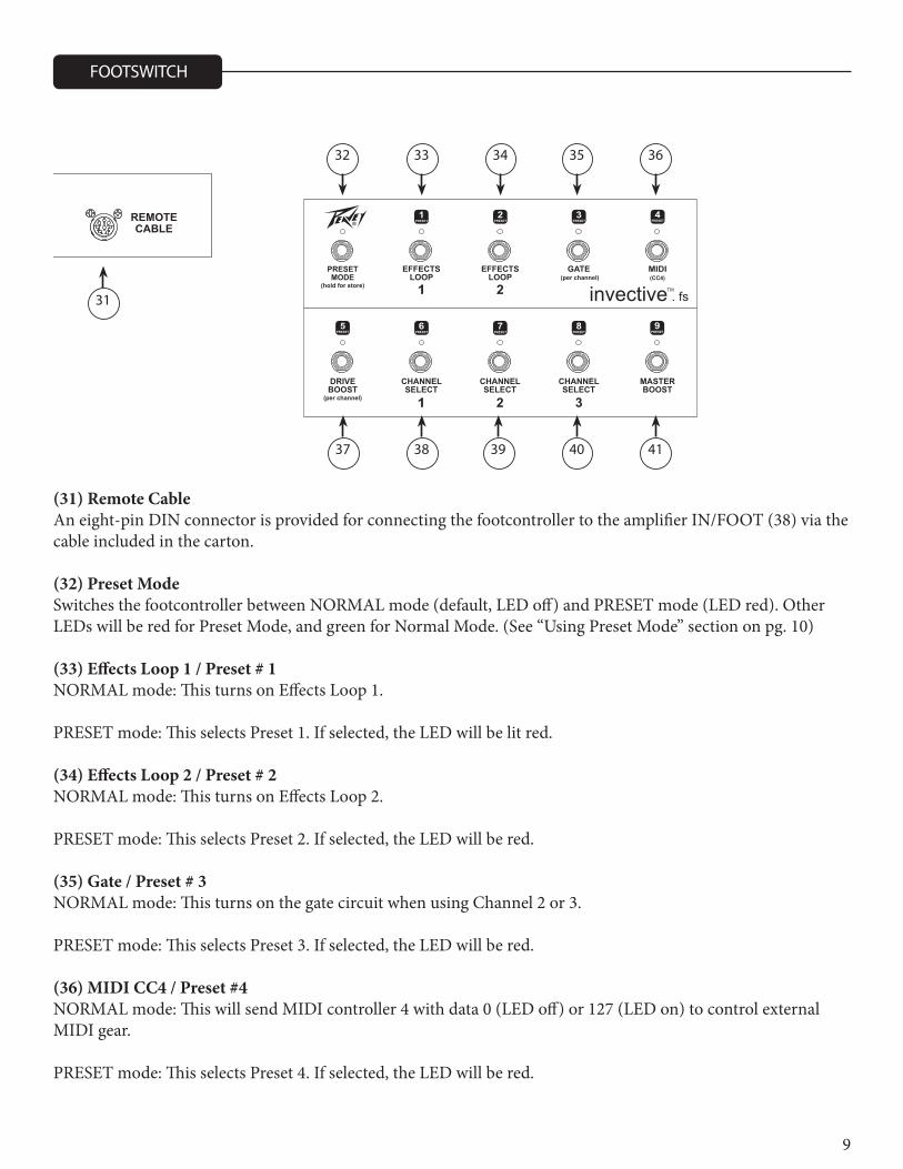
(31) Remote CableAn eight-pin DIN connector is provided for connecting the footcontroller to the amplifier IN/FOOT (38) via the cable included in the carton.
(32) Preset ModeSwitches the footcontroller between NORMAL mode (default, LED off) and PRESET mode (LED red). Other LEDs will be red for Preset Mode, and green for Normal Mode. (See “Using Preset Mode” section on pg. 10)
(33) Effects Loop 1 / Preset # 1NORMAL mode: This turns on Effects Loop 1. PRESET mode: This selects Preset 1. If selected, the LED will be lit red.
(34) Effects Loop 2 / Preset # 2NORMAL mode: This turns on Effects Loop 2.
PRESET mode: This selects Preset 2. If selected, the LED will be red.
(35) Gate / Preset # 3NORMAL mode: This turns on the gate circuit when using Channel 2 or 3.
PRESET mode: This selects Preset 3. If selected, the LED will be red.
(36) MIDI CC4 / Preset #4NORMAL mode: This will send MIDI controller 4 with data 0 (LED off) or 127 (LED on) to control external MIDI gear.
PRESET mode: This selects Preset 4. If selected, the LED will be red.
31
37 38 39 40 41
32 33 34 35 36
10
(37) Drive Boost / Preset #5NORMAL mode: This turns Drive BOOST on and off for the current channel. When switching between chan-nels, this will remember what the last setting was for each. The LED will be green when Drive BOOST is on.
PRESET mode: This selects Preset 5. If selected, the LED will be red.
(38) Channel Select 1 / Preset #6NORMAL mode: This selects Channel 1. The LED will be lit GREEN. If pressed a 2nd time, the channel will return to the previous setting. This allows quick changing between two channels using a single switch.
PRESET mode: This selects Preset 6. If selected, the LED will be red.
(39) Channel Select 2 / Preset #7NORMAL mode: This selects Channel 2. The LED will be lit GREEN. If pressed a 2nd time, the channel will return to the previous setting. This allows quick changing between two channels using a single switch.
PRESET mode: This selects Preset 7. If selected, the LED will be red.
(40) Channel Select 3 / Preset #8NORMAL mode: This selects Channel 3. The LED will be lit GREEN. If pressed a 2nd time, the channel will return to the previous setting. This allows quick changing between two channels using a single switch.
PRESET mode: This selects Preset 8. If selected, the LED will be red.
(41) Master Boost / Preset #9NORMAL mode: This turns the Master Boost on and off. The LED will be lit green.
PRESET mode: This selects Preset 9. If selected, the LED will be red.
Each of the 9 presets remembers the current channel, drive boost on/off, gate on/off, CC4 on/off, effects loop on/off and master boost on/off. Additionally, it remembers the drive boost and gate status of the inactive channels. This way you can, for example, have a clean preset saved without drive boost, and know that when you switch to Channel 2, drive boost will be on.
The amp comes from the factory with 9 default presets that you can modify at will. When the PRESET MODE light is on, you can use the 9 other footswitches to recall those 9 presets. At any time you can switch to NOR-MAL mode and make changes to that sound. This can be during a performance and not permanently stored, or to edit a preset and store to one of the 9 settings.
To store the current settings into one of the 9 presets, you start by holding the PRESET MODE switch down for a second or two, after which the other LEDs will blink (except the one for the current preset which will be on steady – a way to remind you of which preset you were working with). At this point you can press one of the 9 preset switches to store there, or press PRESET MODE again to cancel.
USING PRESET MODE
STORING PRESETS
11
You can initiate this from PRESET mode or from NORMAL mode. After the store (or cancel) it will return to the mode you were in. So you can setup and store 9 presets without ever entering PRESET mode if you wish. It’s typical to set up your sound in NORMAL mode, then store your creation to one of the presets.
As described below, when in preset mode, the 1-9 switches will recall your 9 custom presets. When you press the switch of the preset that is already active, it will toggle the status of the Master Boost. This allows a quick way to recall a preset for a solo and get it boosted very quickly (just hit the switch twice!). Otherwise, you’d have to hit it, then toggle out of preset mode, then hit the Master Boost switch – tap dance! (Of course, you can save the preset with the boost active, and then the 2nd press would disable the boost.) To make the Master Boost status visual while in preset mode (red LEDs for mode/preset) the 9/Master Boost LED will blink green when the boost is en-abled. (If on preset 9, the color will toggle between red and green to show preset number and Master Boost on).
You can connect the MIDI Out to the MIDI In of another Invective 120 to synchronize the two amps. With the footswitch connected to the first amp, any changes you make with the footswitch (or front panel) will be dupli-cated on the 2nd amp – if the 2nd amp is on the same MIDI channel. See MIDI Program Section (pg. 13).
You can also link the MIDI from the amp (or from the 2nd amp) to an effects unit to synchronize presets. If the effects unit can store presets, they can change automatically when you recall presets on the footswitch.
Whenever a preset is recalled, it sends that program change command, followed by the controller status of CC4 (0 or 127 based on the CC4 function) and the controller status of CC10 (0 or 127 based on the MASTER BOOST function). This allows the MIDI effects unit to respond to those controllers to do things like turn a delay on/off, etc. The other footswitches also send CC messages when pressed, but not at preset recall like the above two. (MASTER BOOST sends CC9 AND CC10. CC9 to control another invective, CC10 synced at preset recall for MIDI control of other devices.) See MIDI section for CC numbers generated by each function.
QUICK BOOST
LINKING TO ANOTHER AMP AND/OR EFFECTS UNITS WITH THE MIDI OUT
12
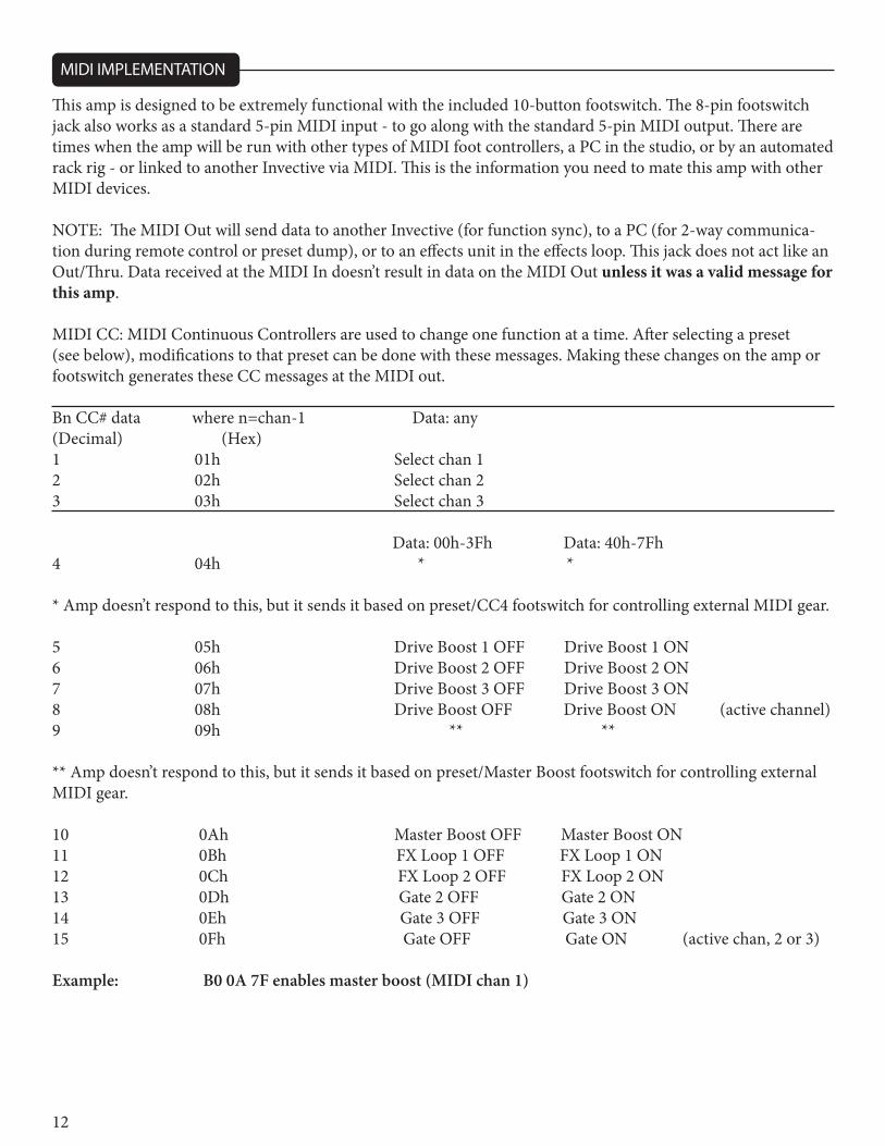
MIDI IMPLEMENTATION
This amp is designed to be extremely functional with the included 10-button footswitch. The 8-pin footswitch jack also works as a standard 5-pin MIDI input - to go along with the standard 5-pin MIDI output. There are times when the amp will be run with other types of MIDI foot controllers, a PC in the studio, or by an automated rack rig - or linked to another Invective via MIDI. This is the information you need to mate this amp with other MIDI devices.
NOTE: The MIDI Out will send data to another Invective (for function sync), to a PC (for 2-way communica-tion during remote control or preset dump), or to an effects unit in the effects loop. This jack does not act like an Out/Thru. Data received at the MIDI In doesn’t result in data on the MIDI Out unless it was a valid message for this amp.
MIDI CC: MIDI Continuous Controllers are used to change one function at a time. After selecting a preset (see below), modifications to that preset can be done with these messages. Making these changes on the amp or footswitch generates these CC messages at the MIDI out.
Bn CC# data where n=chan-1 Data: any(Decimal) (Hex)1 01h Select chan 12 02h Select chan 23 03h Select chan 3
Data: 00h-3Fh Data: 40h-7Fh4 04h * *
* Amp doesn’t respond to this, but it sends it based on preset/CC4 footswitch for controlling external MIDI gear.
5 05h Drive Boost 1 OFF Drive Boost 1 ON6 06h Drive Boost 2 OFF Drive Boost 2 ON7 07h Drive Boost 3 OFF Drive Boost 3 ON8 08h Drive Boost OFF Drive Boost ON (active channel)9 09h ** **
** Amp doesn’t respond to this, but it sends it based on preset/Master Boost footswitch for controlling external MIDI gear.
10 0Ah Master Boost OFF Master Boost ON11 0Bh FX Loop 1 OFF FX Loop 1 ON12 0Ch FX Loop 2 OFF FX Loop 2 ON13 0Dh Gate 2 OFF Gate 2 ON14 0Eh Gate 3 OFF Gate 3 ON15 0Fh Gate OFF Gate ON (active chan, 2 or 3)
Example: B0 0A 7F enables master boost (MIDI chan 1)
13
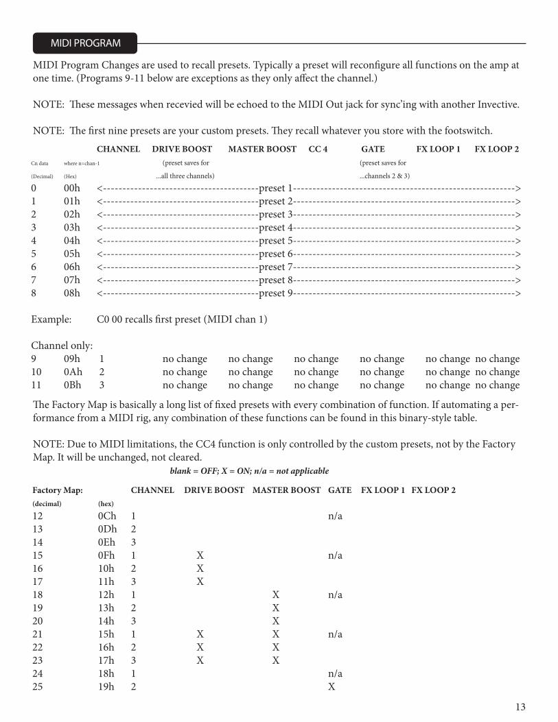
MIDI Program Changes are used to recall presets. Typically a preset will reconfigure all functions on the amp at one time. (Programs 9-11 below are exceptions as they only affect the channel.)
NOTE: These messages when recevied will be echoed to the MIDI Out jack for sync’ing with another Invective.
NOTE: The first nine presets are your custom presets. They recall whatever you store with the footswitch.
MIDI PROGRAM
CHANNEL DRIVE BOOST MASTER BOOST CC 4 GATE FX LOOP 1 FX LOOP 2Cn data where n=chan-1 (preset saves for (preset saves for (Decimal) (Hex) ...all three channels) ...channels 2 & 3) 0 00h <----------------------------------------preset 1--------------------------------------------------------->1 01h <----------------------------------------preset 2--------------------------------------------------------->2 02h <----------------------------------------preset 3--------------------------------------------------------->3 03h <----------------------------------------preset 4--------------------------------------------------------->4 04h <----------------------------------------preset 5--------------------------------------------------------->5 05h <----------------------------------------preset 6--------------------------------------------------------->6 06h <----------------------------------------preset 7--------------------------------------------------------->7 07h <----------------------------------------preset 8--------------------------------------------------------->8 08h <----------------------------------------preset 9--------------------------------------------------------->
Example: C0 00 recalls first preset (MIDI chan 1) Channel only: 9 09h 1 no change no change no change no change no change no change10 0Ah 2 no change no change no change no change no change no change11 0Bh 3 no change no change no change no change no change no change
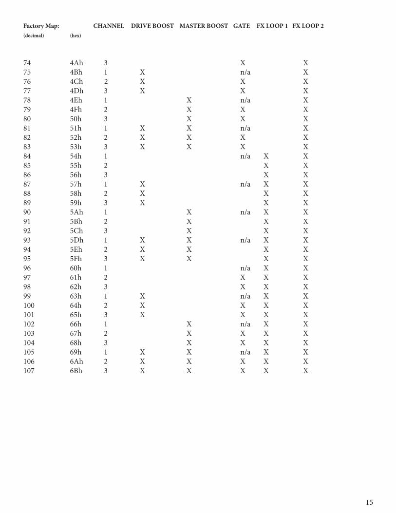
The Factory Map is basically a long list of fixed presets with every combination of function. If automating a per-formance from a MIDI rig, any combination of these functions can be found in this binary-style table.
NOTE: Due to MIDI limitations, the CC4 function is only controlled by the custom presets, not by the Factory Map. It will be unchanged, not cleared.
Factory Map: CHANNEL DRIVE BOOST MASTER BOOST GATE FX LOOP 1 FX LOOP 2 (decimal) (hex) 12 0Ch 1 n/a 13 0Dh 2 14 0Eh 3 15 0Fh 1 X n/a 16 10h 2 X 17 11h 3 X 18 12h 1 X n/a 19 13h 2 X 20 14h 3 X 21 15h 1 X X n/a 22 16h 2 X X 23 17h 3 X X 24 18h 1 n/a 25 19h 2 X
blank = OFF; X = ON; n/a = not applicable

14
Factory Map: CHANNEL DRIVE BOOST MASTER BOOST GATE FX LOOP 1 FX LOOP 2 (decimal) (hex) 26 1Ah 3 X 27 1Bh 1 X n/a 28 1Ch 2 X X 29 1Dh 3 X 30 1Eh 1 X X n/a 31 1Fh 2 X X X 32 20h 3 X X X 33 21h 1 X X n/a 34 22h 2 X X X 35 23h 3 X X X 36 24h 1 n/a X 37 25h 2 X 38 26h 3 X 39 27h 1 X n/a X 40 28h 2 X X 41 29h 3 X X 42 2Ah 1 X n/a X 43 2Bh 2 X X 44 2Ch 3 X X 45 2Dh 1 X X n/a X 46 2Eh 2 X X X 47 2Fh 3 X X X 48 30h 1 n/a X 49 31h 2 X X 50 32h 3 X X 51 33h 1 X n/a X 52 34h 2 X X X 53 35h 3 X X X 54 36h 1 X n/a X 55 37h 2 X X X 56 38h 3 X X X 57 39h 1 X X n/a X 58 3Ah 2 X X X X 59 3Bh 3 X X X X 60 3Ch 1 n/a X61 3Dh 2 X62 3Eh 3 X63 3Fh 1 X n/a X64 40h 2 X X65 41h 3 X X66 42h 1 X n/a X67 43h 2 X X68 44h 3 X X69 45h 1 X X n/a X70 46h 2 X X X71 47h 3 X X X72 48h 1 n/a X73 49h 2 X X
15
Factory Map: CHANNEL DRIVE BOOST MASTER BOOST GATE FX LOOP 1 FX LOOP 2 (decimal) (hex) 26 1Ah 3 X 27 1Bh 1 X n/a 28 1Ch 2 X X 29 1Dh 3 X 30 1Eh 1 X X n/a 31 1Fh 2 X X X 32 20h 3 X X X 33 21h 1 X X n/a 34 22h 2 X X X 35 23h 3 X X X 36 24h 1 n/a X 37 25h 2 X 38 26h 3 X 39 27h 1 X n/a X 40 28h 2 X X 41 29h 3 X X 42 2Ah 1 X n/a X 43 2Bh 2 X X 44 2Ch 3 X X 45 2Dh 1 X X n/a X 46 2Eh 2 X X X 47 2Fh 3 X X X 48 30h 1 n/a X 49 31h 2 X X 50 32h 3 X X 51 33h 1 X n/a X 52 34h 2 X X X 53 35h 3 X X X 54 36h 1 X n/a X 55 37h 2 X X X 56 38h 3 X X X 57 39h 1 X X n/a X 58 3Ah 2 X X X X 59 3Bh 3 X X X X 60 3Ch 1 n/a X61 3Dh 2 X62 3Eh 3 X63 3Fh 1 X n/a X64 40h 2 X X65 41h 3 X X66 42h 1 X n/a X67 43h 2 X X68 44h 3 X X69 45h 1 X X n/a X70 46h 2 X X X71 47h 3 X X X72 48h 1 n/a X73 49h 2 X X
Factory Map: CHANNEL DRIVE BOOST MASTER BOOST GATE FX LOOP 1 FX LOOP 2 (decimal) (hex)
74 4Ah 3 X X75 4Bh 1 X n/a X76 4Ch 2 X X X77 4Dh 3 X X X78 4Eh 1 X n/a X79 4Fh 2 X X X80 50h 3 X X X81 51h 1 X X n/a X82 52h 2 X X X X83 53h 3 X X X X84 54h 1 n/a X X85 55h 2 X X86 56h 3 X X87 57h 1 X n/a X X88 58h 2 X X X89 59h 3 X X X90 5Ah 1 X n/a X X91 5Bh 2 X X X92 5Ch 3 X X X93 5Dh 1 X X n/a X X94 5Eh 2 X X X X95 5Fh 3 X X X X96 60h 1 n/a X X97 61h 2 X X X98 62h 3 X X X99 63h 1 X n/a X X100 64h 2 X X X X101 65h 3 X X X X102 66h 1 X n/a X X103 67h 2 X X X X104 68h 3 X X X X105 69h 1 X X n/a X X106 6Ah 2 X X X X X107 6Bh 3 X X X X X
16
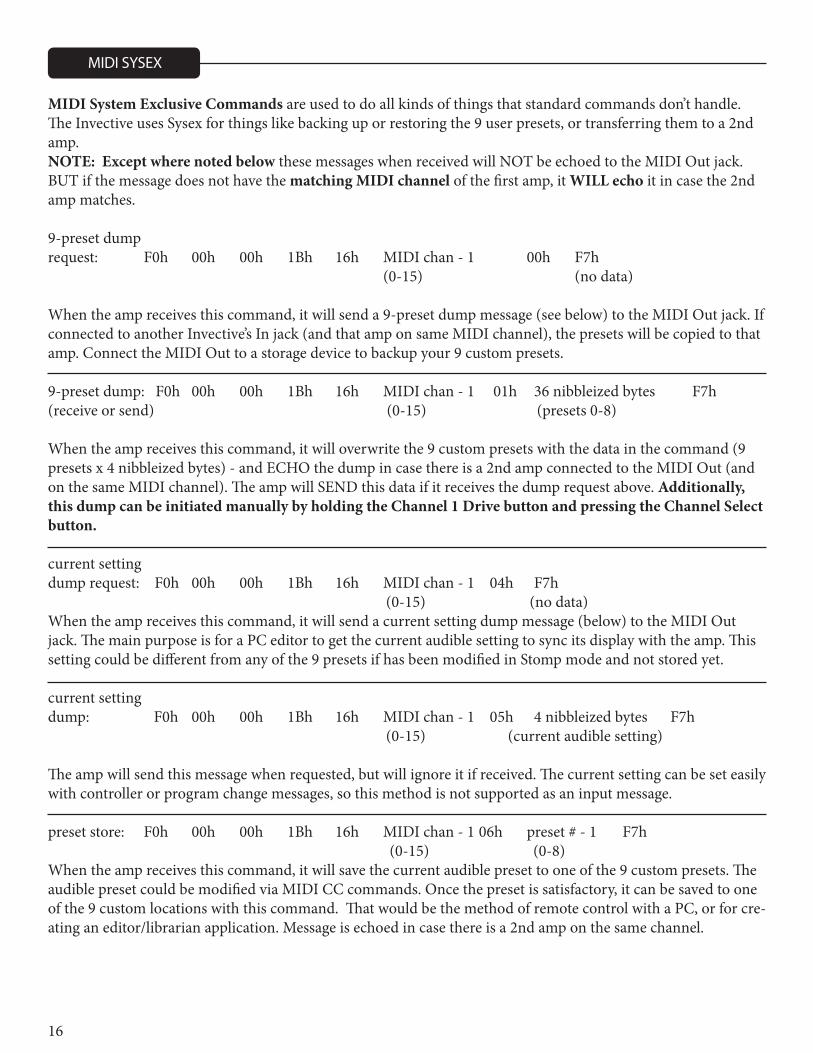
MIDI SYSEX
MIDI System Exclusive Commands are used to do all kinds of things that standard commands don’t handle. The Invective uses Sysex for things like backing up or restoring the 9 user presets, or transferring them to a 2nd amp. NOTE: Except where noted below these messages when received will NOT be echoed to the MIDI Out jack. BUT if the message does not have the matching MIDI channel of the first amp, it WILL echo it in case the 2nd amp matches.
9-preset dump request: F0h 00h 00h 1Bh 16h MIDI chan - 1 00h F7h (0-15) (no data)
When the amp receives this command, it will send a 9-preset dump message (see below) to the MIDI Out jack. If connected to another Invective’s In jack (and that amp on same MIDI channel), the presets will be copied to that amp. Connect the MIDI Out to a storage device to backup your 9 custom presets. 9-preset dump: F0h 00h 00h 1Bh 16h MIDI chan - 1 01h 36 nibbleized bytes F7h (receive or send) (0-15) (presets 0-8) When the amp receives this command, it will overwrite the 9 custom presets with the data in the command (9 presets x 4 nibbleized bytes) - and ECHO the dump in case there is a 2nd amp connected to the MIDI Out (and on the same MIDI channel). The amp will SEND this data if it receives the dump request above. Additionally, this dump can be initiated manually by holding the Channel 1 Drive button and pressing the Channel Select button. current setting dump request: F0h 00h 00h 1Bh 16h MIDI chan - 1 04h F7h (0-15) (no data) When the amp receives this command, it will send a current setting dump message (below) to the MIDI Out jack. The main purpose is for a PC editor to get the current audible setting to sync its display with the amp. This setting could be different from any of the 9 presets if has been modified in Stomp mode and not stored yet. current setting dump: F0h 00h 00h 1Bh 16h MIDI chan - 1 05h 4 nibbleized bytes F7h (0-15) (current audible setting)
The amp will send this message when requested, but will ignore it if received. The current setting can be set easily with controller or program change messages, so this method is not supported as an input message. preset store: F0h 00h 00h 1Bh 16h MIDI chan - 1 06h preset # - 1 F7h (0-15) (0-8) When the amp receives this command, it will save the current audible preset to one of the 9 custom presets. The audible preset could be modified via MIDI CC commands. Once the preset is satisfactory, it can be saved to one of the 9 custom locations with this command. That would be the method of remote control with a PC, or for cre-ating an editor/librarian application. Message is echoed in case there is a 2nd amp on the same channel.
17
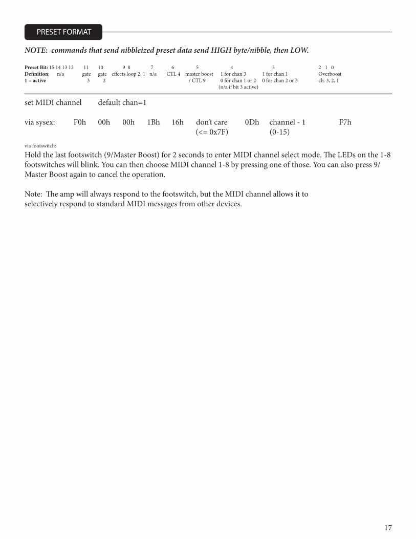
NOTE: commands that send nibbleized preset data send HIGH byte/nibble, then LOW. Preset Bit: 15 14 13 12 11 10 9 8 7 6 5 4 3 2 1 0Definition: n/a gate gate effects loop 2, 1 n/a CTL 4 master boost 1 for chan 3 1 for chan 1 Overboost1 = active 3 2 / CTL 9 0 for chan 1 or 2 0 for chan 2 or 3 ch. 3, 2, 1 (n/a if bit 3 active)
set MIDI channel default chan=1 via sysex: F0h 00h 00h 1Bh 16h don’t care 0Dh channel - 1 F7h (<= 0x7F) (0-15) via footswitch:
Hold the last footswitch (9/Master Boost) for 2 seconds to enter MIDI channel select mode. The LEDs on the 1-8 footswitches will blink. You can then choose MIDI channel 1-8 by pressing one of those. You can also press 9/Master Boost again to cancel the operation.
Note: The amp will always respond to the footswitch, but the MIDI channel allows it toselectively respond to standard MIDI messages from other devices.
PRESET FORMAT
18
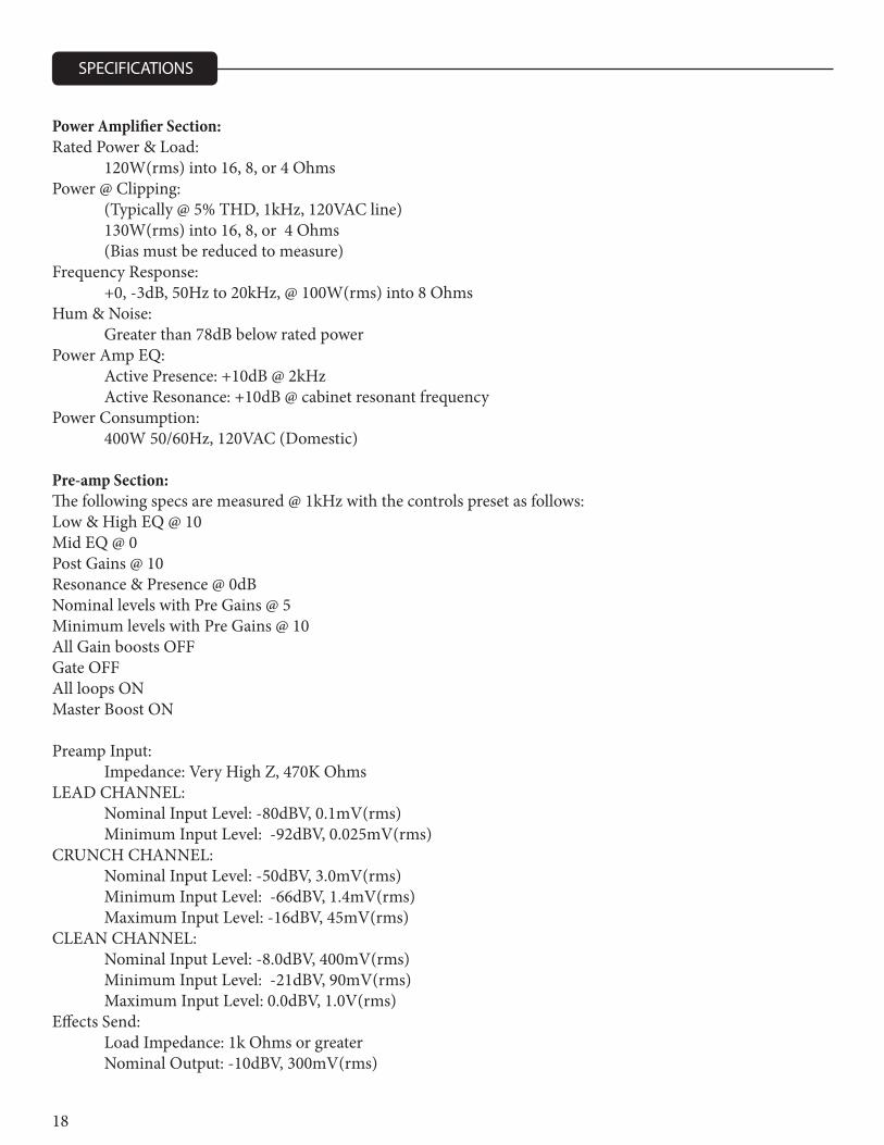
Power Amplifier Section:Rated Power & Load: 120W(rms) into 16, 8, or 4 OhmsPower @ Clipping: (Typically @ 5% THD, 1kHz, 120VAC line) 130W(rms) into 16, 8, or 4 Ohms (Bias must be reduced to measure)Frequency Response: +0, -3dB, 50Hz to 20kHz, @ 100W(rms) into 8 OhmsHum & Noise: Greater than 78dB below rated powerPower Amp EQ: Active Presence: +10dB @ 2kHz Active Resonance: +10dB @ cabinet resonant frequencyPower Consumption: 400W 50/60Hz, 120VAC (Domestic)
Pre-amp Section:The following specs are measured @ 1kHz with the controls preset as follows:Low & High EQ @ 10Mid EQ @ 0Post Gains @ 10Resonance & Presence @ 0dBNominal levels with Pre Gains @ 5Minimum levels with Pre Gains @ 10All Gain boosts OFFGate OFFAll loops ONMaster Boost ON
Preamp Input: Impedance: Very High Z, 470K OhmsLEAD CHANNEL: Nominal Input Level: -80dBV, 0.1mV(rms) Minimum Input Level: -92dBV, 0.025mV(rms)CRUNCH CHANNEL: Nominal Input Level: -50dBV, 3.0mV(rms) Minimum Input Level: -66dBV, 1.4mV(rms) Maximum Input Level: -16dBV, 45mV(rms)CLEAN CHANNEL: Nominal Input Level: -8.0dBV, 400mV(rms) Minimum Input Level: -21dBV, 90mV(rms) Maximum Input Level: 0.0dBV, 1.0V(rms)Effects Send: Load Impedance: 1k Ohms or greater Nominal Output: -10dBV, 300mV(rms)
SPECIFICATIONS
19
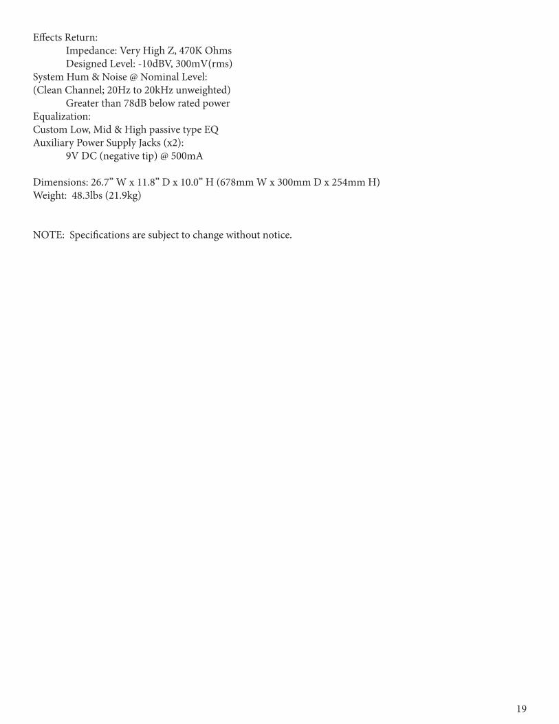
Effects Return: Impedance: Very High Z, 470K Ohms Designed Level: -10dBV, 300mV(rms)System Hum & Noise @ Nominal Level:(Clean Channel; 20Hz to 20kHz unweighted) Greater than 78dB below rated powerEqualization:Custom Low, Mid & High passive type EQAuxiliary Power Supply Jacks (x2): 9V DC (negative tip) @ 500mA
Dimensions: 26.7” W x 11.8” D x 10.0” H (678mm W x 300mm D x 254mm H)Weight: 48.3lbs (21.9kg)
NOTE: Specifications are subject to change without notice.

20
Logo referenced in Directive 2002/96/EC Annex IV(OJ(L)37/38,13.02.03 and defined in EN 50419: 2005The bar is the symbol for marking of new waste and
is applied only to equipment manufactured after13 August 2005
www.peavey.comWarranty registration and information for U.S. customers available online at
www.peavey.com/warrantyor use the QR tag below
Features and speci�cations subject to change without notice.
Peavey Electronics Corporation 5022 Hartley Peavey Drive Meridian, MS 39305 (601) 483-5365 FAX (601) 486-1278
80307558