Embed Size (px)
Citation preview

ClimaCheck Sweden AB, Box 46, SE-131 06 Nacka, Sweden Delivery address: Gamla Värmdövägen 6, SE-131 37 Nacka Sweden Tel.: +46 (0)8-50 255 250, Email: [email protected] Web: www.climacheck.com
Operating Manual
Energy and Power Meter
ClimaCheck EP Scout
2017-01-23

EP Scout Operating Manual – 2016-02-04 Page 2 of 19
Table of Contents
1 Overview ...................................................................................................................... 3
2 Technical Specifications .................................................................................................. 4
3 Power Measurement ....................................................................................................... 5
4 System configuration ..................................................................................................... 7
4.1 Modbus connection ................................................................................................... 7
4.2 Different voltage systems .......................................................................................... 7
4.3 Motor configurations ................................................................................................. 8
4.4 Systems with inverter ............................................................................................... 9
4.5 Differential protection ............................................................................................... 9
5 ClimaCheck EP Scout configuration ................................................................................. 10
5.1 Configuration of CT type ........................................................................................... 10
5.2 Resetting energy count ............................................................................................ 12
5.3 Configuration of data scalar ...................................................................................... 12
5.4 Using more than one Power Meter EP Scout with ClimaCheck PA Pro .............................. 13
5.4.1 Configuration of EP Scout as a second power meter .............................................. 13
5.4.2 Configuration of PA Pro for a second power meter ................................................. 13
6 Cable Extension ............................................................................................................ 15
6.1 Extending Rogowski coils .......................................................................................... 15
6.2 Extending clamps and split-core CTs .......................................................................... 15
7 Troubleshooting ............................................................................................................ 16
7.1 Display on EP scout does not light up ......................................................................... 16
7.2 Display on EP Scout shows data but no data is read ..................................................... 16
7.2.1 Communication problem .................................................................................... 16
7.2.2 PA Pro configuration problem ............................................................................. 16
7.2.3 Datasource problem .......................................................................................... 18
7.3 Error in measurements – Power does not correspond to expected ................................. 18

EP Scout Operating Manual – 2016-02-04 Page 3 of 19
1 Overview
ClimaCheck EP Scout is an energy power meter that will register all relevant electrical properties to
analyse active power, current, voltage power factor and energy consumed by a refrigeration, air-
conditioning or heat pump system. It can be used for all electrical systems from 1 phase with
neutral to 3 phases with or without neutral. It is a vital part to the ClimaCheck Performance
Analyser systems.
Data is collected from the ClimaCheck EP Scout through Modbus/RS485, a bus protocol that allows
communication over relatively long distances and also wireless communication modems can be
used if required. Please consult Modbus communication manuals or contact ClimaCheck for further
advice on special applications.
The Modbus address is set to 1 as default, if several meters are used the address must be changed
as described in the manual.
The ClimaCheck EP Scout was introduced to allow the use of Rogowski coils with the standard
range of 5 to 4000 Amps as well as clamps with good accuracy on small systems with a range from
0.5 to 150 Amps. The EP Scout is powered by L1 and L2.

EP Scout Operating Manual – 2016-02-04 Page 4 of 19
2 Technical Specifications
Service type 3 phase with/without neutral, 1 phase
Voltage channels 80-346 VACLN, 600VLL, CAT III
Current channels 0.525 VAC max, 333 mV CTs, measuring up to 4000A with Rogowski coils
Line frequency 50/60 Hz
Waveform sampling 12 kHz
Accuracy 0.2% (<0.1% typical) ANSI, C12.20-2010 Class 0.2
Communication RS485
Operating temperature -7 to 60 °C (-20 to 140 °F)
Humidity 5% to 95% non-condensing
Enclosure ABS plastic, 94-V0 flammability rating

EP Scout Operating Manual – 2016-02-04 Page 5 of 19
3 Power Measurement
Experience shows that the biggest challenge for ClimaCheck users is to apply power measurements
correctly. We recommend outmost care when applying sensors as it can often be difficult to follow
cables in confined spaces. Always compare measured currents and power with rating plate’s
nominal data at start of measurements.
Warning - Working with electricity is potentially dangerous and should only be conducted by people with appropriate competencies and in accordance with local regulations.
The voltage measurement inputs of the EP Scout has an over voltage transient protection of CAT
III. They may be connected to equipment of CAT III or lower as specified by IEC 61010. The table
below contains a summary of the definitions for each category:
CAT IV Origin of installation, utility level and any outside cable run.
CAT III Distribution wiring, including mains bus, feeders and branch circuits as well as permanently installed loads.
CAT II Receptacle outlet circuit and plug-in loads.
CAT I Protected electronic circuits.
Power measurement on refrigeration systems presents many possibilities for mistakes and
inaccuracies, but proper care and observance of the following points will ensure that correct results
are obtained.
Efficiency and COP values do not depend on the power measurement, so for system diagnostic
purposes and system optimisation the precision of the input power is less important than pressures
and temperatures. Where verification of capacity and power input is required, it is essential that
the correct equipment is used and that it is applied correctly. The following procedures are
recommended in these cases.
The ClimaCheck specified accuracy for power and capacity is dependent on:
- Use of suitable equipment. Current transformers (CTs) and clamps are available with
different ranges and accuracies. They are often primarily designed for measurement of
current where the influence of phase shift is not of primary interest. The equipment
supplied by ClimaCheck measures with low errors from phase shift and current when used
correctly.
- Use of the equipment within appropriate range. Manufacturers of power and current
measuring equipment normally rate equipment errors as a percent of full scale (FS). Due to
an increase in error they do not normally rate for accuracy below a certain range when
there is phase shift. The Rogowski coils have a minimum limit of 5 A, whereas the clamps’
limit is 0.5A. Below this range, there will be an increasing risk of deviation of accuracy from
the manufacturer’s stated percent FS error.
Adjustment of Rogowski or current clamp usage is described in section 5.1.
Follow the steps below to assure proper power and energy readings:
- It is important to only measure the power to the compressor. Make sure the measurement
is done after the point where circulation pumps and fans are connected.
- Make sure that the voltage and current for each phase corresponds with the markings on
the measuring equipment and that the arrow on the current clamps is pointing in the
direction of the current.

EP Scout Operating Manual – 2016-02-04 Page 6 of 19
- Make sure that the current clamps and coils are completely closed and that the contact
areas are clean.
- Check that the connections are correct by reading the voltage, current and power on the
display of the power meter. If you find a problem remove the clamps and attach L1
followed by a control and the repeat the process for L2 and L3.
With the help of the visual display on the EP Scout, real-time values can be read directly from the
meter. The display has 2 rows of 16 characters along with a push button at one end of the EP
Scout that controls the display scroll mode.
When the display button is held down for 5 seconds, the EP Scout will switch between AUTO CYCLE
mode (switch screens every 2 seconds) and MANUAL CYCLE (the button must be pressed to switch
screens).
When in auto cycle mode, the informational screens change every 2–3 seconds, with real-time
values updated every second. The “display” button will stop the cycle until it is pressed again or
until 20 seconds is reached. Some information, such as protocol, CT type, volts, amps, kW, power
factor, is displayed during each cycle.
Another helpful feature of the EP Scout are the 3 bi-colour CT LEDs, which turn green when the CTs
are properly installed, with correct orientation and on correct phase.
EP Scout Operating Manual – 2016-02-04 Page 7 of 19
4 System configuration
4.1 Modbus connection
Below is shown the connection to the serial cable used for connecting the EP Scout to the portable
ClimaCheck PA Pro. As standard, the system is supplied with a short flat cable that can be
extended with a standard serial cable with D-sub contacts in each end.
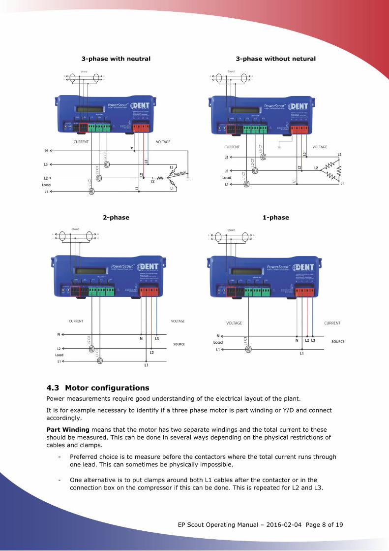
4.2 Different voltage systems
The EP Scout can be used to measure the following electrical systems:
- 3-phase with neutral - 3-phase without neutral - 2-phase - 1-phase
The current transformers and the voltage cables should be connected according to the electrical
system diagrams below.
EP Scout Operating Manual – 2016-02-04 Page 8 of 19
3-phase with neutral 3-phase without netural
2-phase 1-phase
4.3 Motor configurations
Power measurements require good understanding of the electrical layout of the plant.
It is for example necessary to identify if a three phase motor is part winding or Y/D and connect
accordingly.
Part Winding means that the motor has two separate windings and the total current to these
should be measured. This can be done in several ways depending on the physical restrictions of
cables and clamps.
- Preferred choice is to measure before the contactors where the total current runs through
one lead. This can sometimes be physically impossible.
- One alternative is to put clamps around both L1 cables after the contactor or in the
connection box on the compressor if this can be done. This is repeated for L2 and L3.

EP Scout Operating Manual – 2016-02-04 Page 9 of 19
- It is possible to measure with 6 clamps i.e. 2 in parallel to the instrument per phase.
- If there is no way to connect around the total current an acceptable approximation can be
achieved by measuring on one of the contactors (the one with largest power draw is
preferred) and adjusting the power scale in the ClimaCheck software Input tab. The ratios
are typically 50/50 or 60/40 and can be deduced by moving the clamp back and forth.
4.4 Systems with inverter
If inverters are used it is normally necessary to measure before inverter and use a loss factor of
typically 3-6% to compensate for the heat loss. This factor is added under electrical motor losses in
the Constant tab of the ClimaCheck software. Ensure that i.e. fans do not consume power from the
same feed. If so an offset can be added in the input tab
4.5 Differential protection
Differential protection is used to improve the security of the installation and will cut the supply if
any current is drawn outside the “protected loop”. As the EP Scout is powered by the voltage line
L1 and L2, differential protection must be taken into account when connecting.

EP Scout Operating Manual – 2016-02-04 Page 10 of 19
5 ClimaCheck EP Scout configuration
This section explains how to change the most common settings on the EP Scout.
5.1 Configuration of CT type
The EP Scout can be used together with 150A current clamps and Rogowski coils. In order to
change the CT type, the power meter should be accordingly configured as follows:
- Install the ViewPoint software found on the USB memory.
- Connect the EP Scout to the computer via the provided USB cable. - Launch the ViewPoint software. - Select the correct PC COM Port which states “DENT USB” - Click on the “Connect” button. The model number and the firmware version of the EP Scout
will be shown.
- Move to the “Meter Setup” page and click on “Retrieve Meter Setup”.
EP Scout Operating Manual – 2016-02-04 Page 11 of 19
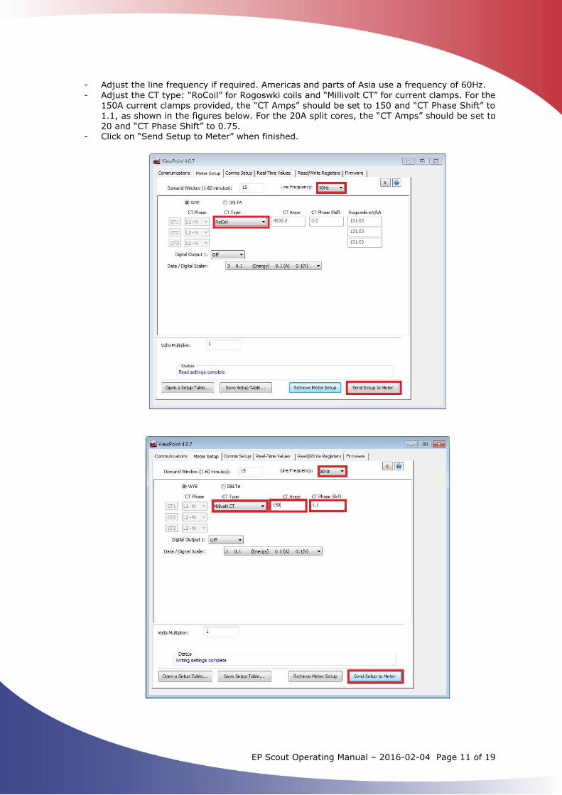
- Adjust the line frequency if required. Americas and parts of Asia use a frequency of 60Hz.
- Adjust the CT type: “RoCoil” for Rogoswki coils and “Millivolt CT” for current clamps. For the 150A current clamps provided, the “CT Amps” should be set to 150 and “CT Phase Shift” to 1.1, as shown in the figures below. For the 20A split cores, the “CT Amps” should be set to 20 and “CT Phase Shift” to 0.75.
- Click on “Send Setup to Meter” when finished.
EP Scout Operating Manual – 2016-02-04 Page 12 of 19
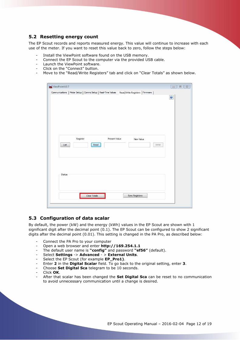
5.2 Resetting energy count
The EP Scout records and reports measured energy. This value will continue to increase with each
use of the meter. If you want to reset this value back to zero, follow the steps below:
- Install the ViewPoint software found on the USB memory. - Connect the EP Scout to the computer via the provided USB cable. - Launch the ViewPoint software. - Click on the “Connect” button. - Move to the “Read/Write Registers” tab and click on “Clear Totals” as shown below.
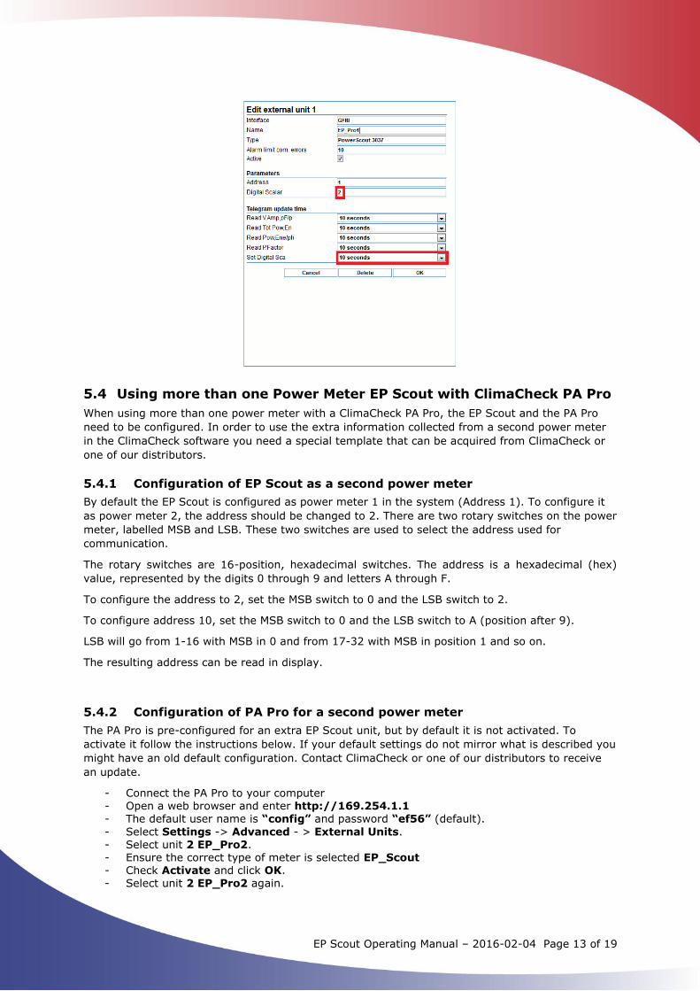
5.3 Configuration of data scalar
By default, the power (kW) and the energy (kWh) values in the EP Scout are shown with 1
significant digit after the decimal point (0.1). The EP Scout can be configured to show 2 significant
digits after the decimal point (0.01). This setting is changed in the PA Pro, as described below:
- Connect the PA Pro to your computer - Open a web browser and enter http://169.254.1.1 - The default user name is “config” and password “ef56” (default). - Select Settings -> Advanced - > External Units. - Select the EP Scout (for example EP_Pro1).
- Enter 2 in the Digital Scalar field. To go back to the original setting, enter 3.
- Choose Set Digital Sca telegram to be 10 seconds. - Click OK. - After that scalar has been changed the Set Digital Sca can be reset to no communication
to avoid unnecessary communication until a change is desired.
EP Scout Operating Manual – 2016-02-04 Page 13 of 19
5.4 Using more than one Power Meter EP Scout with ClimaCheck PA Pro
When using more than one power meter with a ClimaCheck PA Pro, the EP Scout and the PA Pro
need to be configured. In order to use the extra information collected from a second power meter
in the ClimaCheck software you need a special template that can be acquired from ClimaCheck or
one of our distributors.
5.4.1 Configuration of EP Scout as a second power meter
By default the EP Scout is configured as power meter 1 in the system (Address 1). To configure it
as power meter 2, the address should be changed to 2. There are two rotary switches on the power
meter, labelled MSB and LSB. These two switches are used to select the address used for
communication.
The rotary switches are 16-position, hexadecimal switches. The address is a hexadecimal (hex)
value, represented by the digits 0 through 9 and letters A through F.
To configure the address to 2, set the MSB switch to 0 and the LSB switch to 2.
To configure address 10, set the MSB switch to 0 and the LSB switch to A (position after 9).
LSB will go from 1-16 with MSB in 0 and from 17-32 with MSB in position 1 and so on.
The resulting address can be read in display.
5.4.2 Configuration of PA Pro for a second power meter
The PA Pro is pre-configured for an extra EP Scout unit, but by default it is not activated. To
activate it follow the instructions below. If your default settings do not mirror what is described you
might have an old default configuration. Contact ClimaCheck or one of our distributors to receive
an update.
- Connect the PA Pro to your computer - Open a web browser and enter http://169.254.1.1 - The default user name is “config” and password “ef56” (default).
- Select Settings -> Advanced - > External Units. - Select unit 2 EP_Pro2. - Ensure the correct type of meter is selected EP_Scout - Check Activate and click OK. - Select unit 2 EP_Pro2 again.

EP Scout Operating Manual – 2016-02-04 Page 14 of 19
- The data scalar can be set here as well; check section 5.3 for more information.
- Set the Read telegrams to 10 seconds, as shown below.
- Click OK. - Select Settings -> Advanced -> Channels.
- Scroll down to channel 130 and check the boxes to the right of the channels 130-132 and 136-138. Check that the channel names correspond to the image below.
- Click Save. - Select Settings -> Advanced -> Databases.
- The following channel names should have been added to your database items list:
- The configuration is complete. Close the web browser.

EP Scout Operating Manual – 2016-02-04 Page 15 of 19
6 Cable Extension
Cables of the Rogowski coils, the clamps, and the split-core CTs can be extended if necessary. Heat
shrink butt splices can be used for splicing.
6.1 Extending Rogowski coils
The Rogowski coils can be extended up to 30m (100 ft) using extensions of the same wire
type/AWG. The wire type for the Rogowski coils is: Shielded cable with thermoplastic insulation,
1000VAC VW-1, 2x26AWG, 80°C, cURus.
If the connector supplied by ClimaCheck cannot be used, the cables should be connected as shown
below.
6.2 Extending clamps and split-core CTs
The clamps and the split-core CTs can be extended up to 150m (500 ft) using extensions of the
same wire type/AWG. The wire type for the Rogowski coils is: 600V Rated VW-1, 105°C, 20AWG,
black and white twisted pair, cURus.
If the connector supplied by ClimaCheck cannot be used, the cables should be connected as shown
below.

EP Scout Operating Manual – 2016-02-04 Page 16 of 19
7 Troubleshooting
In case of trouble with the EP Scout, please refer to the suggested actions described in this chapter
or contact ClimaCheck Sweden or ClimaCheck reseller for support.
7.1 Display on EP scout does not light up
Check the voltage between L1 and L2 with a multimeter (voltage meter). The voltage should be
80-600 VAC in order for the EP Scout to power up.
7.2 Display on EP Scout shows data but no data is read
7.2.1 Communication problem
When communicating properly, the LEDs on the PA Pro for RS485 RD (receive data) and TD
(transmit data) should flash. Simultaneously, the COM LED on the EP Scout should flash green.
- Check the cable
The address and baud rate 57600 of the EP Scout should match the those configured in the PA Pro.
- Check the address of the EP Scout. See section 5.4.1 and baudrate 57 600.
Check the configured address in the PA Pro. See section 5.4.2 to log in to the PA Pro. Go to
Settings > Advanced > External units and select the unit in question. Make sure the
address is correct and the settings correspond the picture below.
- In order to make sure that there is no communication problem, go to Settings >
Advanced > External units > View Values. The unit is question should light green, and
real-time values should be shown.
7.2.2 PA Pro configuration problem
Go to Settings > Advanced > External units > Connections and make sure that all incoming
values from EP Scout are connected to their corresponding channels in the PA Pro.
Below is the result for a system where EP Scout 1 is active whereas EP Scout 2 is not connected.

EP Scout Operating Manual – 2016-02-04 Page 17 of 19
Each measured value from the EP Scout is here connected to channels that can be stored in the PA
Pro and read by the software or sent to the Internet server of ClimaCheck online. The colour and
status indication show status.
If the unit channels are not connected, please refer to the PA Pro manual on how to connect
External Units values to Channels in PA Pro.
The above channels need to be activated in order to be read by the software or sent to ClimaCheck
online. Go to Settings > Advanced >Channels and make sure that the box for short term
Databases in channel list is ticked.

EP Scout Operating Manual – 2016-02-04 Page 18 of 19
7.2.3 Datasource problem
After making sure that values are shown in the PA Pro, that they are connected to their
corresponding channels, and the channels are activated, make sure to use a correct datasource in
the ClimaCheck software. The incoming values from the PA Pro channel list should be connected to
correct variables in the software.
7.3 Error in measurements – Power does not correspond to expected
Always compare measured currents and power with rating plates and/or nominal data at start of
measurements.
Experience shows that the biggest challenge for ClimaCheck users is to apply power measurements
correctly. We recommend outmost care when applying sensors as it can often be difficult to follow
cables in confined housings.
Make sure that the voltage cables are connected depending on the electrical system (see section
4.2) and that the EP Scout is configured for the correct CT (see section 5.1)
Make sure that the 3 CT LEDs on the EP Scout are flashing green.
Check the following on the EP Scout display:
- Phase sequence
- Total power and power per phase
- Current
If current is unbalanced, check that clamps are fully closed. If wrong level, check CT
configuration and make sure that the complete compressor current and only compressor
current is measured. Typically current per phase is not allowed to vary so that any phase
deviate more than 10% from the average for a three phase motor.
- Voltage
Typically voltage per phase is not allowed to vary so that any phase deviate more than
10% from the average for a three phase motor.
- Power per phase
If the power is uneven check the above points about current and voltage. If any power is
negative but voltage and current are correctly matched, the CT is turned in the wrong
direction or wires between CT and meters crossed.
- Power factor per phase and total
At full load, power factor is 0.75-0.95 for three phase motors – higher for large/high
efficiency motors – but it can decrease significantly at low/part load. It is common that
voltage measurement to one or several power meters is taken from one place with a fused
auxiliary supply and it can be a challenge to follow cables to the point where CTs are
applied, frequently a significant distance from the voltage measurement point.
Error in power factor is typically caused by:
i. Mismatching voltage and current or direction of current
To validate the match, if possible, measure with a multimeter in voltage position. Put
one probe at the terminal in the direct vicinity of the CT and the other to the
corresponding voltage input at the power meter. This voltage should be 0 V whereas if
the probe is moved to another phase on the meter it should show the full line to line
voltage.
ii. Interference on phase shift/Power factor by influence on CT wiring from power line
Phase shift/Power factor values are sensitive to interference caused by power lines.
Good practice for wiring of sensor leads should always be respected to avoid problems

EP Scout Operating Manual – 2016-02-04 Page 19 of 19
e.g. sensor cables should be separated from power cables and not run parallel to power
cables without proper separators/shielding.
If power factor is inconsistent, wiring should be inspected and separation/shielding
introduced if cables can be affected by magnetic fields from power cables.
Sensor cables can cross power lines at right angle but should not be run in parallel and
never in bundles with power cables.
iii. Resistance in CT cables
Wire resistance that cause larger “burden” than allowed for a CT will affect the phase
shift/power factor. Always respect wire length and size as specified in section 6, to avoid
to decrease accuracy. Typically the phase shift increase=power factor decrease with a
burden above the allowed.
Check if part winding or double cables are used and not correctly measured (see section 4.3).
Ensure that only compressor power is measured (pumps/fans should not be included in compressor
power). If compressor cannot be measured separately, make an offset for accessories in the
software.
If inverters are used, it is normally necessary to measure before inverter and use a loss factor of
typically 3-6% to compensate for the heat loss (inverter manufacturers can often give loss factor
for their specific units). Power factor for inverters are typically close to 1. If the power factor is
wrong or uneven, the phase order or the match between voltage and current are normally not
correct.


![Untitled-2 [] · FS 78 FS 68 , FOCUS ÉkJ ËFOCUS FS 78 FS 68 FS 68 , , , FS 68 Foundation FS 68 , FS 68 68 fi , FOCUS F-s 688 , , 68 , 688 FOCUS FS , FS 68 , , , 688 ,](https://img.pdfslide.us/doc/110x75/5b75f9b67f8b9a3b7e8b5e04/untitled-2-fs-78-fs-68-focus-ekj-efocus-fs-78-fs-68-fs-68-fs-68.jpg)