Embed Size (px)
Citation preview
Operating ManualOperating Manual7320.9607320.961 /.962 /.963
powered by
Drawing ID:A 31495 02 IT 74
ContentsContents
A
Safety Notes 1Designated Use 2Handle 7320.960 - Functional Description 3-6Handle 7320.960 - Installation 7Handle Electronics - Functional Description 8-10Transponder 7320.961/.962 - Functional Description 11-13Programming Transponder 7320.963 - Functional Description 14-42Notes on Maintenance 43Technical Specifications Handle 44Emergency Opening – Handle 45
IntroductionIntroduction
Rittal products represent highest quality standards and rich functionality. The systems are compatible with access systems from SimonsVoss Technologies AG.
This operating manual informs you about the characteristics and possible fields of application of the transponder system.The manual also explains installation, operation, and programming of the products.
Safety NotesSafety Notes
- Caution!!! Install the handle with the enclosure door open!!! Check the functioning when the enclosure door is open!!! Do NOT close the enclosure door during installation and functional test!!!
- Danger of injury to the hands! Danger of contusion when operating the enclosure door handle.
- Always replace both batteries (backup battery)!!! When inserting the backup battery, there should be no main battery in the battery case!!!- Caution: The battery of the transponder must not be removed as this may result in loss of data.
- The handle must not be used for other than Rittal enclosures.
- The electrical lines of the CMC-TC transponder sensor must always be installed in a manner separated from electrical lines to which mains voltage is applied.
- The systems must not be used in conditions other than those specified as environmental conditions.
- Safety systems must not be deactivated or by-passed.
- The handle must not come into direct contact with water (e. g. dew), oily dirt or aggressive substances.
- Operation in hazardous environments containing combustible gases or vapours is prohibited. Protection against water and dust must be ensured by installation into an enclosure/rack so that the rear part is located in the protected area in the enclosure/door frame.
- The handle must be installed according to the relevant rules described in the separate installation instructions.
1

Designated Use
The transponder series‘ design corresponds to the state-of-the-art in technology and complies with the relevant safety rules.The handle only serves for opening and locking of non-walkable steel furniture and enclosures.
The manufacturer does not assume liability for damage resulting from any use not complying with the designated use. The user is responsible for complying with the designated use.
Complying with this operating manual is the prerequisite for the designated use of the equipment.
In addition to the operating manual, the relevant statutory andother binding regulations on prevention of accidents and on environmental protection must be observed.
The transponder series must not be installed and connected by other than a trained and qualified electrician according to the rules and regulations regarding electrical installations and the notes laid down in this manual.
2
Caution!!! Install the handle with the enclosure dooropen!!! Check the functioning when the enclosure door isopen!!! Do NOT close the enclosure door during installationand functional test!!!
Danger of injury to the hands!Danger of contusion when operating theenclosure door handle.
Handle 7320.960 - Functional Description The enclosure handle is used to lock enclosures inindustrial environments (switchgear, control,machine enclosure). It is designed for indoor application.
The handle is a locking mechanism equipped with electronicsand a solenoid instead of a cylinder lock. It was designed tomeet the dimensions of standardisedinstallation openings enabling retrofit in an existing enclosurewithout problems. Moreover, it can be fully integratedinto an existing network of an IT security system orof an access control system (time zone control).
3
Note !!!
The handle series is shipped in the so-called ”zero mode”!Zero mode means that the handle series
can be opened at any time by a third person,using a zeroed transponder.
Neutralising the zero mode:
You must program the handle and transponder so that no third person can open the enclosure.
By reprogramming the handle and the transponder,you automatically neutralise
the zero mode (programming, see page 14 f.).For this purpose, a Programming
Transponder 7320.963 is required.

Handle 7320.960 -Functional Description
The enclosure handle of the transponder series can bedeployed in the following variants:
- single unit The enclosure has one door which is locked by the handle.
- two enclosure handles in one enclosure The enclosure has two doors (front and rear) which are locked by one enclosure handle each.
- network with many enclosure handles In this case, enclosure handles form a network (CMC-TC transponder transmitter 7320.962 required).
4
Main Advantages
- small design, no additional space or installation depth required in the enclosure- no cabling (stand-alone solution)- integration option for network systems- transponder technology- optimised haptics- low-effort assembly- tap-proof data transfer- lost transponders are simply locked for the system- BSI 7500-certified; locking and organisation program certified according to Bundesamt für Sicherheit und Informationstechnik (German authority for security and information technology)- all access is logged for later evaluation (Plus version)- freely programmable

Handle 7320.960 - Functional Description
1. Lever
2. Pushbutton
1. Lever = lever to open and lock the enclosure 2. Pushbutton = to release the lever after transponder operation
Sequence for opening an enclosure door:
• Operate transponder (press blue button).• An acoustic signal is output.• Press pushbutton (2) (within 6 seconds).• Lever snaps out up from the locking mechanism.• Push lever (2) upwards and pull.• Door is unlocked and opened.
5

Handle 7320.960 - Functional Description
Cover platefor electronic components andbattery
Connection rodfor latch, rod lockmechanism, etc.
Pushbutton mechanism
6
For installation you need a Torx 25 screw driver.
Caution!!! Install the handle with the enclosure door open!!!Check the functioning when the enclosuredoor is open!!! Do NOT close the enclosure door duringinstallation and functional test!!!
Proceed as follows when installing the enclosure handle:
Place and hold the enclosure handle to the front of the door withthe handle open. Insert the rod into the existing rod mechanism.Then you can turn in the two fastening screws. In case of glazeddoors a bevel adapter is placed between handle and door.
Please refer to enclosed installation instructions.
Handle 7320.960 - Installation
7
Handle Electronics - Functional Description
Battery Warning
Warning Stage - Main Battery
If the main battery of the handle is about to be exhausted, multiple short acoustic signals will be output at short intervals after operating the transponder before the solenoid of the handle engages. The battery then has to be replaced promptly.
Warning Stage - Backup Battery
Now, only the acoustic signals are output for approx. 30 secondsindicating the backup battery warning (without main battery warning).The handle will not engage until the end of the backup battery warning. The backup battery is now active. Both batteries must now be replaced as soon as possible.
If this warning is still ignored, the door can either be opened 50 more times, or, without further operation, the handle will shut down after 4-5 weeks. In both cases the door will only open if Config Device or PalmCD are used (SimonsVoss configuration products).
8

Handle Electronics - Functional DescriptionReplacing the Battery
Replacing the battery must not be carried out by other thanqualified authorised personnel. Only batteries supplied bySimonsVoss may be used.
Remove the handle from the enclosure door(refer to Installation of the Handle).
The electronic components and the batteries are located inthe lower part of the handle.
• Loosen screw A.
• Remove cover B.
• Carefully pull out the electronic assembly from thehousing.
Always replace both batteries(backup battery)!!!
When inserting the backupbattery, there should be nomain battery in the batterycase!!!
9
AB B
Handle Electronics - Functional Description
Replacing the Battery
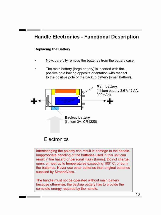
• Now, carefully remove the batteries from the battery case.
• The main battery (large battery) is inserted with thepositive pole having opposite orientation with respect to the positive pole of the backup battery (small battery).
Lithium Battery 3,6 VoltSize ½ AA
Main battery(lithium battery 3.6 V ½ AA,900mAh)
Backup battery(lithium 3V, CR1220)
++
Electronics
Interchanging the polarity can result in damage to the handle. Inappropriate handling of the batteries used in this unit can result in fire hazard or personal injury (burns). Do not charge, open, or heat up to temperatures exceeding 100° C, or burn the batteries. Never use other batteries than original batteries supplied by SimonsVoss.
The handle must not be operated without main battery because otherwise, the backup battery has to provide the complete energy required by the handle.
10

Transponder 7320.961 / .962 – Functional DescriptionThe 7320.961/.962 transponder is a digital key which is programmedusing the 7320.963 programming transponder. The transponderprovides contact-free operation and does not only replace themechanical key but also provides the functions of an ID card.Encrypted communication between transponder and locking cylinderor lock is initiated by simply pressing a button.
All functions are released by pressing a button. The functions includeopening and closing of doors, steel enclosures, etc., payment ofcanteen bills, as well as timekeeping of working times at the terminal,or access to PC networks and activation of alarm systems.
If a transponder is lost, it is simply locked without having to replace asingle handle.
11
Transponder7320.961
Pushbutton (blue area)
Fitting hole forkey ring, etc.
Location of the antenna
The 7320.962 transponder is equipped with two lines. These can beconnected to a relay locking contact. Here, closing of the contactreplaces the pressing of the blue pushbutton.Using this transponder, the handles can be linked to the CMC TC.For that purpose, the CMC-TC room door output module 7320.740is required. The transponder then has to be mounted on the internalframe of the enclosure behind the handle (see installationinstructions).
As the handle series works using active transponder technology, the 7320.961 transponder has a separate voltage supply (battery). The advantage with respect to passive technology lies in the lower energy consumption of the handle series and in increased transmissionrange.
In order to release an action, hold the transponder near the handle,and press the transponder button. If the transponder is authorised for digital locking of the handle, then the door can opened.
The housing is protected against dripping water. However, it is not waterproof.
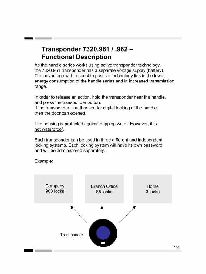
Each transponder can be used in three different and independentlocking systems. Each locking system will have its own password and will be administered separately.
Example:
Branch Office85 locks
Home3 locks
Company900 locks
12
Transponder
Transponder 7320.961 / .962 – Functional Description
Replacing the Battery
If the battery voltage of the transponder tends to be low, eight short acoustic signals will be output at short intervals after operating the transponder at the handle after disengaging.
Caution: The battery of the transponder must not be removed as this may result in loss of data.
In case of a battery warning, please send the respective transponder to:
SimonsVoss Technologies AG Eichenweg 6D-07616 Petersberg
for replacement of the battery, or contact your responsibleSimonsVoss system support.
13
Transponder 7320.961 / .962 – Functional Description
Programming Transponder 7320.963 - Functional Description
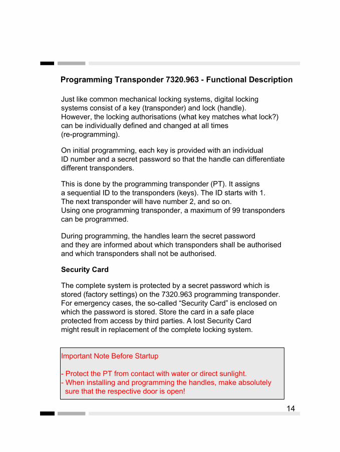
Just like common mechanical locking systems, digital locking systems consist of a key (transponder) and lock (handle). However, the locking authorisations (what key matches what lock?)can be individually defined and changed at all times (re-programming).
On initial programming, each key is provided with an individual ID number and a secret password so that the handle can differentiate different transponders.
This is done by the programming transponder (PT). It assigns a sequential ID to the transponders (keys). The ID starts with 1. The next transponder will have number 2, and so on.Using one programming transponder, a maximum of 99 transponderscan be programmed.
During programming, the handles learn the secret password and they are informed about which transponders shall be authorised and which transponders shall not be authorised.
Security Card
The complete system is protected by a secret password which is stored (factory settings) on the 7320.963 programming transponder. For emergency cases, the so-called “Security Card” is enclosed on which the password is stored. Store the card in a safe place protected from access by third parties. A lost Security Card might result in replacement of the complete locking system.
Important Note Before Startup
- Protect the PT from contact with water or direct sunlight.- When installing and programming the handles, make absolutely sure that the respective door is open!
14
Programming Transponder 7320.963 - Functional Description
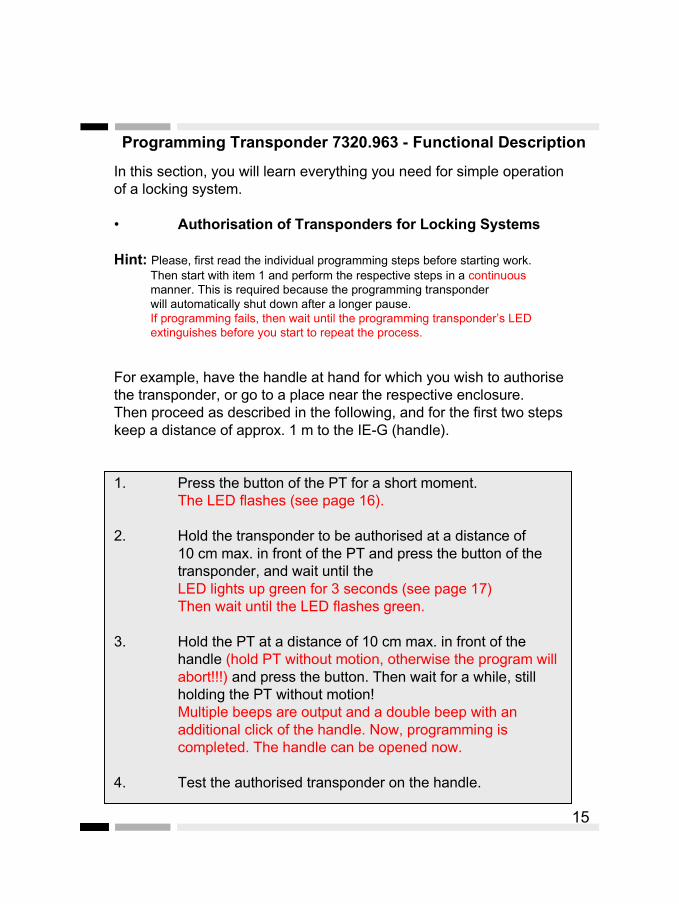
In this section, you will learn everything you need for simple operationof a locking system.
• Authorisation of Transponders for Locking Systems
Hint: Please, first read the individual programming steps before starting work. Then start with item 1 and perform the respective steps in a continuous manner. This is required because the programming transponder will automatically shut down after a longer pause. If programming fails, then wait until the programming transponder’s LED extinguishes before you start to repeat the process.
For example, have the handle at hand for which you wish to authorisethe transponder, or go to a place near the respective enclosure.Then proceed as described in the following, and for the first two stepskeep a distance of approx. 1 m to the IE-G (handle).
1. Press the button of the PT for a short moment.The LED flashes (see page 16).
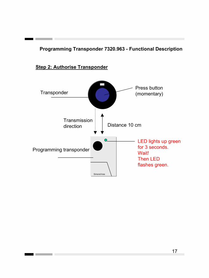
2. Hold the transponder to be authorised at a distance of10 cm max. in front of the PT and press the button of thetransponder, and wait until theLED lights up green for 3 seconds (see page 17)Then wait until the LED flashes green.
3. Hold the PT at a distance of 10 cm max. in front of thehandle (hold PT without motion, otherwise the program willabort!!!) and press the button. Then wait for a while, stillholding the PT without motion!Multiple beeps are output and a double beep with anadditional click of the handle. Now, programming iscompleted. The handle can be opened now.
4. Test the authorised transponder on the handle.
15

Programming Transponder 7320.963 - Functional Description
If you wish to program other transponders, repeat steps 1-4.
If multiple transponders are to be authorised for the same handle, follow the instructions in step 1. Then repeat step 2 for eachadditional transponder you wish to authorise and then perform steps 3 and 4. When testing multiple transponders, please note that each test will take approx. 8 seconds.
In case you have authorised a transponder for the wrong handle, repeat steps 1-4 in order to lock the transponder again.
16SimonsVoss
Distance 10 cm
Programming transponder
Transponder
LED flashes green
Step 1: Authorise Transponder
Press button 1 x (momentary)
Transmission direction
Programming Transponder 7320.963 - Functional Description
17
SimonsVoss
Distance 10 cm
Programming transponder
Transponder
LED lights up green for 3 seconds.Wait!Then LED flashes green.
Press button (momentary)
Step 2: Authorise Transponder
Transmission direction

Programming Transponder 7320.963 - Functional Description
18
SimonsVoss
Distance10 cmmax.!!!
LED flashes green
Step 3: Authorise Transponder
))))))))))
Multiple beeps are output and a double beep with an additional click. The handle can be opened now.
Press button momentary and hold for 10 secondsin direction of IE-G.
Transmission direction
If not multiple beeps (contact interrupted), then repeat programming!!! Important: hold PTin direction of handle without motion!

Programming Transponder 7320.963 - Functional Description
19
Distance 10 cm max.!!!
Step 4: Test
)))))))))) Confirmation by acoustic signal(short beep) plusclick sound.
Press button
Transmission direction
Programming Transponder 7320.963 - Functional Description
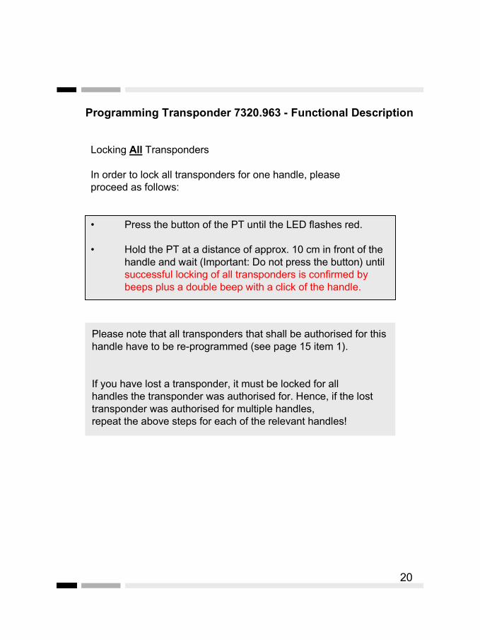
Locking All Transponders
In order to lock all transponders for one handle, pleaseproceed as follows:
• Press the button of the PT until the LED flashes red.
• Hold the PT at a distance of approx. 10 cm in front of thehandle and wait (Important: Do not press the button) untilsuccessful locking of all transponders is confirmed by beeps plus a double beep with a click of the handle.
Please note that all transponders that shall be authorised for thishandle have to be re-programmed (see page 15 item 1).
If you have lost a transponder, it must be locked for allhandles the transponder was authorised for. Hence, if the losttransponder was authorised for multiple handles,repeat the above steps for each of the relevant handles!
20
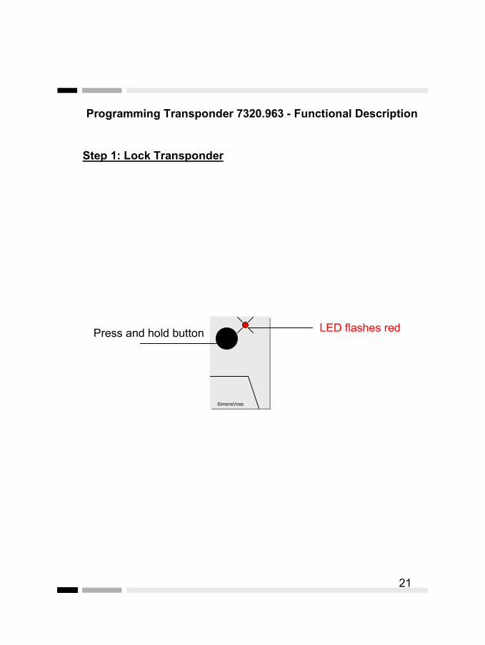
Programming Transponder 7320.963 - Functional Description
21
SimonsVoss
LED flashes red
Step 1: Lock Transponder
Press and hold button
Programming Transponder 7320.963 - Functional Description
22
SimonsVoss
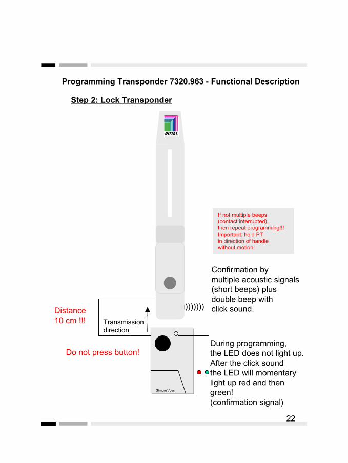
Distance 10 cm !!!
Step 2: Lock Transponder
Confirmation by multiple acoustic signals(short beeps) plusdouble beep with click sound.
Do not press button!
If not multiple beeps(contact interrupted),then repeat programming!!!Important: hold PTin direction of handlewithout motion!
During programming, the LED does not light up.After the click soundthe LED will momentary light up red and then green!(confirmation signal)
))))))))))
Transmission direction
Programming Transponder 7320.963 - Functional Description
Example:
You have an enclosure (E) with the handle, and in the office doora digital locking cylinder (O). You wish to authorise your own transponderfor the front door and the enclosure. However, the transponder for youremployee shall only lock and unlock the office door.
Proceed as follows:
• Go to the enclosure (E) and there only authorise your owntransponder.
• Then go to the office door (O). There, authorise your owntransponder and then the one of your employee.
Now, using your own transponder you can operate the office door (O)and the enclosure (E). The transponder of your employee will only openthe office door.
If, some days later, your employee loses the transponder, you can decideto lock that transponder for the office door for safety‘s sake. Also, you canauthorise the replacement transponder for your employee you either hadat hand or that you purchased from your supplier.
23

Programming Transponder 7320.963 - Functional Description
Locking all transponders for the enclosure:
• Take the PT to the enclosure.
• Lock all transponders as described on page 20.
• Re-authorise your own transponder for theenclosure.
• Authorise your employee‘s replacementtransponder (see page15) for the enclosure.
As the transponder of the employee was not authorised for the enclosure door, no changes are required with respect to the enclosure door!
The “old” transponder of the employee is now locked for the enclosure.
24
Programming Transponder 7320.963 –Functional Description
Additional Functions
In the following, some additional functions are described that you canperform using the PT (programming transponder). However, these functions are not essential for operation of the overall system.
Specific locking of the ID number of a transponder.
In order specifically to lock a lost transponder for a handle, you requirethe ID number of the lost transponder.
Therefore, we recommend to maintain a list of the owners and the ID numbers of the respective transponders.
Reading data using the ID number of a transponder:
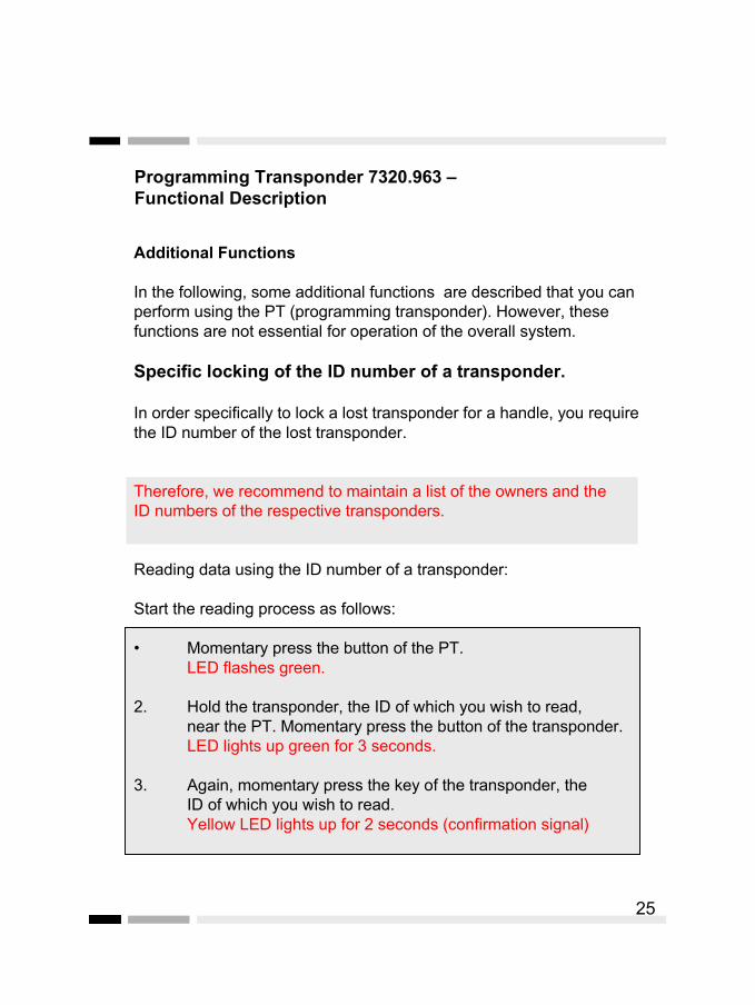
Start the reading process as follows:
• Momentary press the button of the PT. LED flashes green.
2. Hold the transponder, the ID of which you wish to read, near the PT. Momentary press the button of the transponder.LED lights up green for 3 seconds.
3. Again, momentary press the key of the transponder, the ID of which you wish to read.Yellow LED lights up for 2 seconds (confirmation signal)
25
Programming Transponder 7320.963 –Functional Description
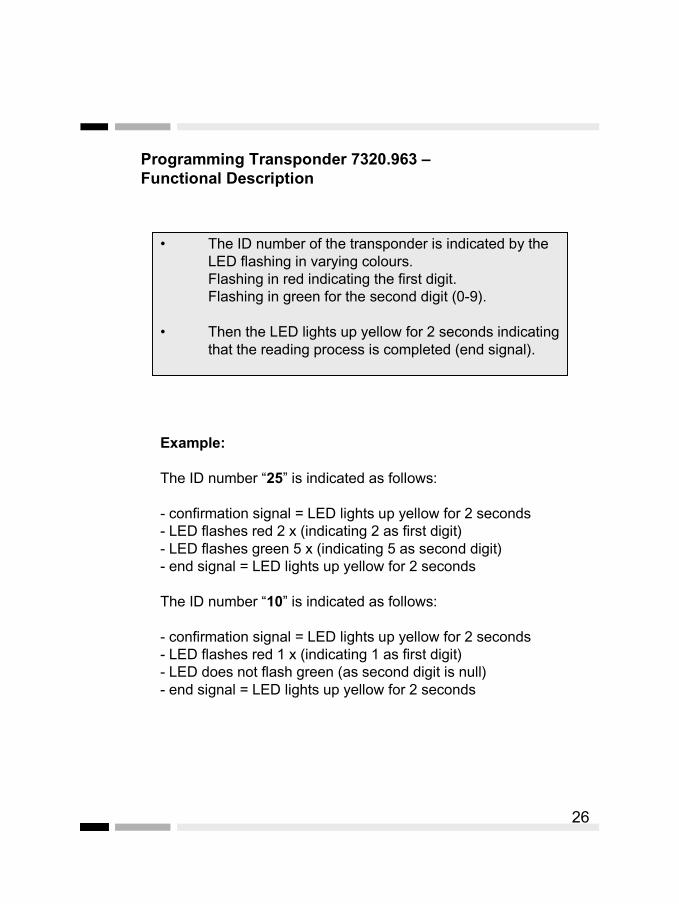
• The ID number of the transponder is indicated by theLED flashing in varying colours.Flashing in red indicating the first digit.Flashing in green for the second digit (0-9).
• Then the LED lights up yellow for 2 seconds indicatingthat the reading process is completed (end signal).
Example:
The ID number “25” is indicated as follows:
- confirmation signal = LED lights up yellow for 2 seconds- LED flashes red 2 x (indicating 2 as first digit)- LED flashes green 5 x (indicating 5 as second digit)- end signal = LED lights up yellow for 2 seconds
The ID number “10” is indicated as follows:
- confirmation signal = LED lights up yellow for 2 seconds - LED flashes red 1 x (indicating 1 as first digit)- LED does not flash green (as second digit is null)- end signal = LED lights up yellow for 2 seconds
26
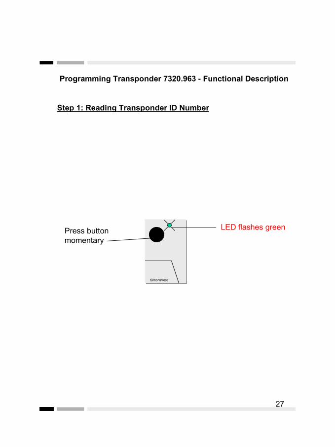
Programming Transponder 7320.963 - Functional Description
27
SimonsVoss
LED flashes green
Step 1: Reading Transponder ID Number
Press button momentary

Programming Transponder 7320.963 - Functional Description
28
SimonsVoss
Distance 10 cm
Transponder
LED lights up green for3 seconds
Press button (momentary)
Step 2: Reading Transponder ID Number
Transmissiondirection
Programming Transponder 7320.963 - Functional Description
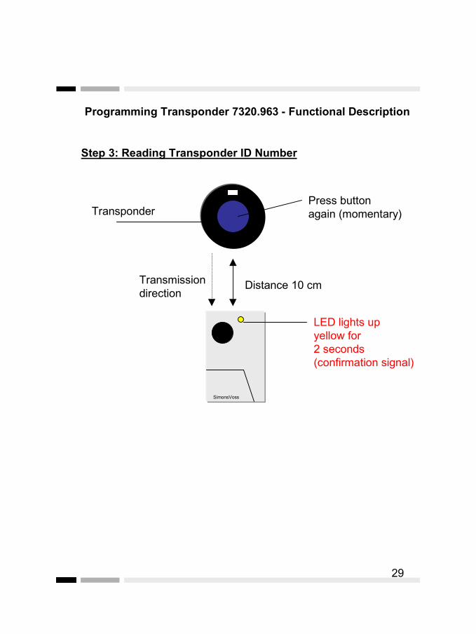
29
SimonsVoss
Distance 10 cm
Transponder
LED lights up yellow for2 seconds (confirmation signal)
Press button again (momentary)
Step 3: Reading Transponder ID Number
Transmissiondirection
Programming Transponder 7320.963 - Functional Description
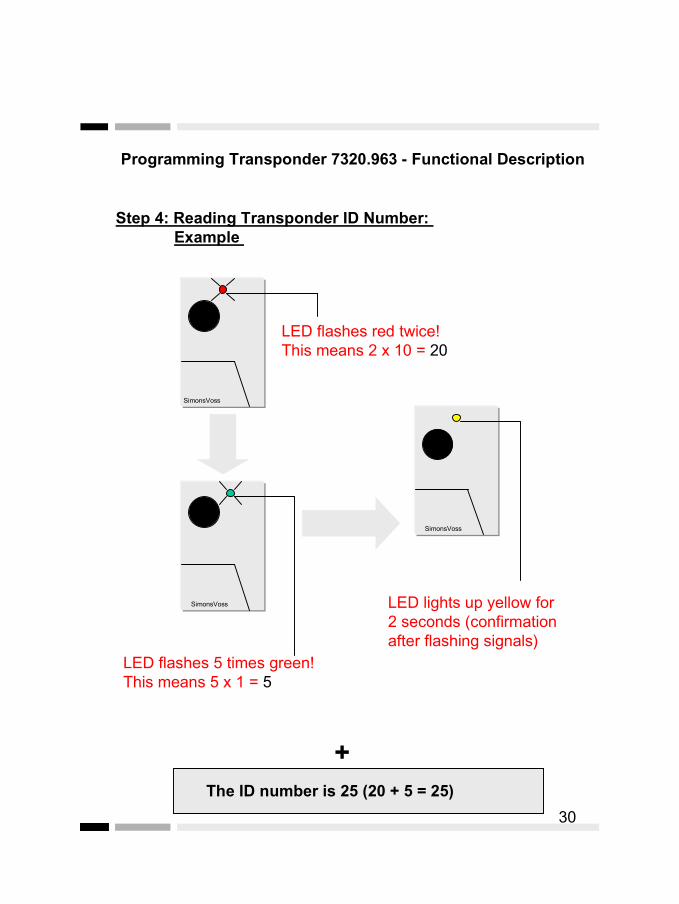
30
SimonsVoss
LED lights up yellow for2 seconds (confirmationafter flashing signals)
Step 4: Reading Transponder ID Number: Example
SimonsVoss
SimonsVoss
LED flashes red twice!This means 2 x 10 = 20
LED flashes 5 times green!This means 5 x 1 = 5
+The ID number is 25 (20 + 5 = 25)

Programming Transponder 7320.963 –Functional Description
Specific deletion of lost transponders:
Now that you know the ID number of a lost transponder, youcan lock that specific transponder accordingly. Proceed as follows:
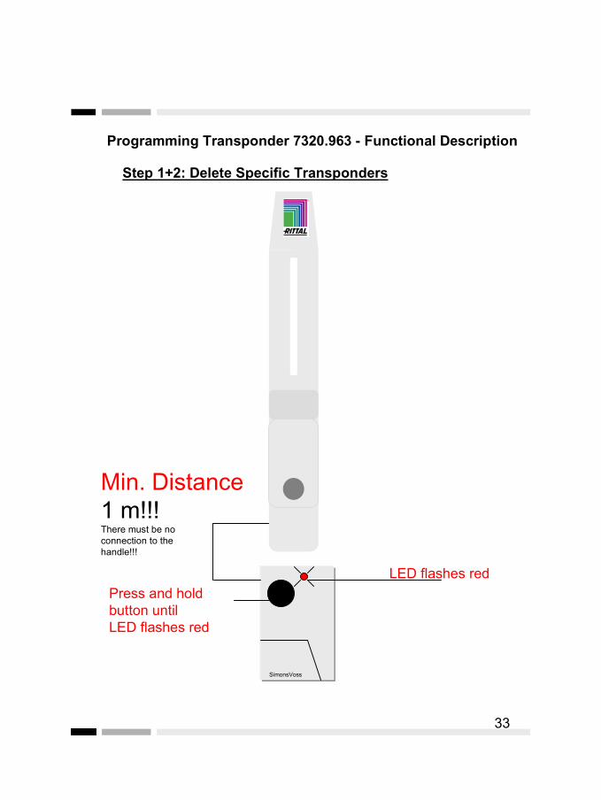
• Take the PT to the handle for which you wish to lock thelost transponder (at first, please keep a minimum distanceof at least 1 m!)
• Press the button of the PT until the LED flashes red –then release the button.
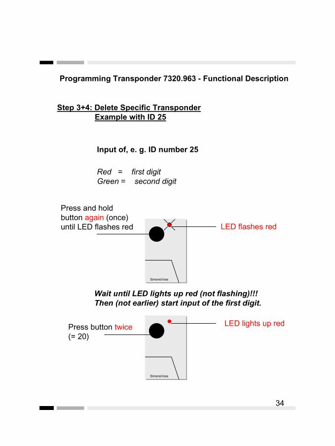
• Immediately press the button of the PT again until the LEDflashes red, and release the button.Then the LED starts flashing red and then green,depending on the number of transponders programmed(less than 10 programmed transponders, then first green;10 or more programmed transponders, then red at first).Important:While the LED lights up, red or green, start the input ofthe ID number (If the LED has extinguished, then you havewaited too long. In such cases, please repeat the processstarting from step 1).
• Proceed as follows to enter the ID number of thetransponder to be locked:
The LED of the PT starts to light up red (green): now, enterthe number for the first digit (second digit) by pressing thebutton of the PT. Please wait for a moment.
The LED of the PT starts to light up green: now, enter thenumber for the last digit by pressing the button of the PT.Please wait for a moment.
31

Programming Transponder 7320.963 –Functional Description
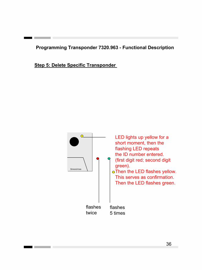
5. After input of the ID number, the PT will confirmyour input.The LED will light up yellow for a short moment, theID will be repeated in red (first digit) and green(last digit). Then the LED lights up yellow again.(Confirmation).After confirmation, the LED flashes green.
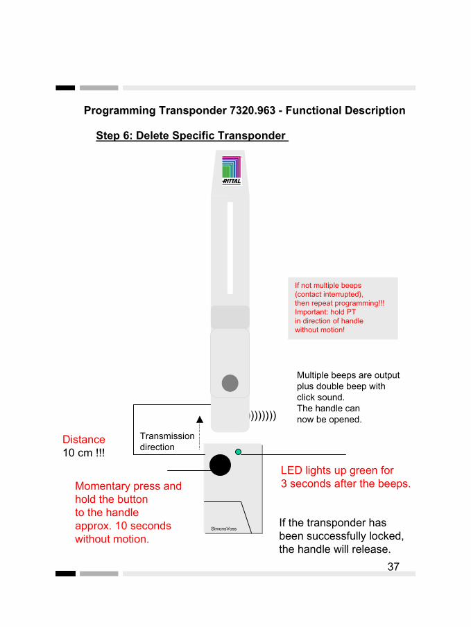
6. If the ID displayed is correct, then hold the PT ata short distance to the handle while the LED flashesgreen, and press the button of the PT.Important: Hold the PT in direction of the handlewithout motion!!!
Wait until multiple beeps and a double beep with aclick are output in order to confirm the programming.
If the transponder has been successfully locked,then the handle releases.
Example:
Proceed as follows to enter the ID number “25”:
- Wait until the LED lights up red, then press the button of the PT twice (input for 2 as first digit).
- Wait until the LED lights up green, then press the button of the PT 5 times (input for 5 as last digit).
32
Programming Transponder 7320.963 - Functional Description
33
SimonsVoss
Min. Distance
1 m!!!There must be no connection to the handle!!!
LED flashes red
Step 1+2: Delete Specific Transponders
Press and hold button until LED flashes red
Programming Transponder 7320.963 - Functional Description
34
SimonsVoss
LED flashes red
Step 3+4: Delete Specific Transponder Example with ID 25
Press and hold button again (once) until LED flashes red
Input of, e. g. ID number 25
Red = first digitGreen = second digit
SimonsVoss
LED lights up redPress button twice (= 20)
Wait until LED lights up red (not flashing)!!! Then (not earlier) start input of the first digit.

Programming Transponder 7320.963 - Functional Description
35
SimonsVoss
LED lights up green
Step 4: Delete Specific Transponder Example with ID 25
Input of ID number 25
Red = first digitGreen = second digit
SimonsVoss
LED lights up green
Press button 5 x (= 5)
After input of the first digit, please wait for a short moment until the LED lights up green!!!
Now, start the input of the second digit.
Programming Transponder 7320.963 - Functional Description
36
SimonsVoss
Step 5: Delete Specific Transponder
LED lights up yellow for a short moment, then the flashing LED repeats the ID number entered. (first digit red; second digit green).Then the LED flashes yellow.This serves as confirmation. Then the LED flashes green.
flashes twice
flashes 5 times
Programming Transponder 7320.963 - Functional Description
37
SimonsVoss
Distance 10 cm !!!
LED lights up green for3 seconds after the beeps.
Step 6: Delete Specific Transponder
Momentary press and hold the buttonto the handleapprox. 10 secondswithout motion.
If the transponder has been successfully locked, the handle will release.
If not multiple beeps(contact interrupted),then repeat programming!!!Important: hold PTin direction of handlewithout motion!
Multiple beeps are outputplus double beep with click sound.The handle can now be opened.))))))))))
Transmission direction
Programming Transponder 7320.963 - Functional Description
If you do not know the ID number of a lost transponder,then proceed as described on page 20 (Lock All Transponders)!!!
38
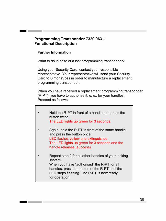
Further Information
What to do in case of a lost programming transponder?
Using your Security Card, contact your responsible representative. Your representative will send your Security Card to SimonsVoss in order to manufacture a replacement programming transponder.
When you have received a replacement programming transponder (R-PT), you have to authorise it, e. g., for your handles. Proceed as follows:
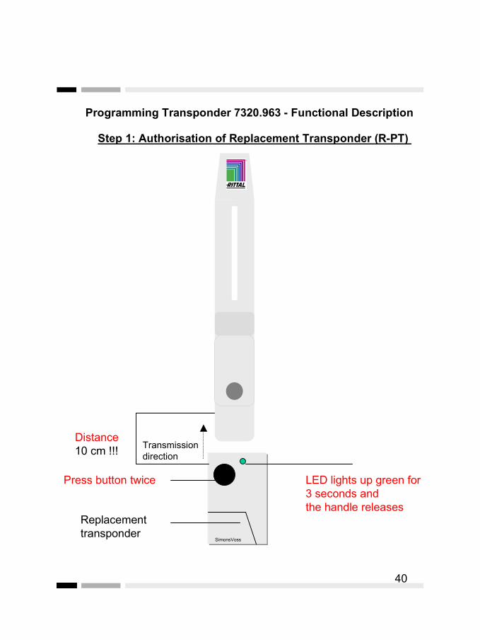
• Hold the R-PT in front of a handle and press the button twice. The LED lights up green for 3 seconds.
• Again, hold the R-PT in front of the same handle and press the button once.LED flashes yellow and extinguishes. The LED lights up green for 3 seconds and the handle releases (success).
• Repeat step 2 for all other handles of your locking system.
When you have “authorised” the R-PT for all handles, press the button of the R-PT until the LED stops flashing. The R-PT is now ready for operation!
Programming Transponder 7320.963 –Functional Description
39
Programming Transponder 7320.963 - Functional Description
40
SimonsVoss
LED lights up green for3 seconds and the handle releases
Step 1: Authorisation of Replacement Transponder (R-PT)
Press button twice
Replacement transponder
Distance 10 cm !!! Transmission
direction

Programming Transponder 7320.963 - Functional Description
41
SimonsVoss
LED lights up yellow and extinguishes.
Then the LED lights up green for 3 secondsand the handle releases.
Step 2: Authorisation of Replacement Transponder (R-PT)
Press buttononce again
Replacement transponder
Distance 10 cm !!! Transmission
direction
Programming Transponder 7320.963 - Functional Description
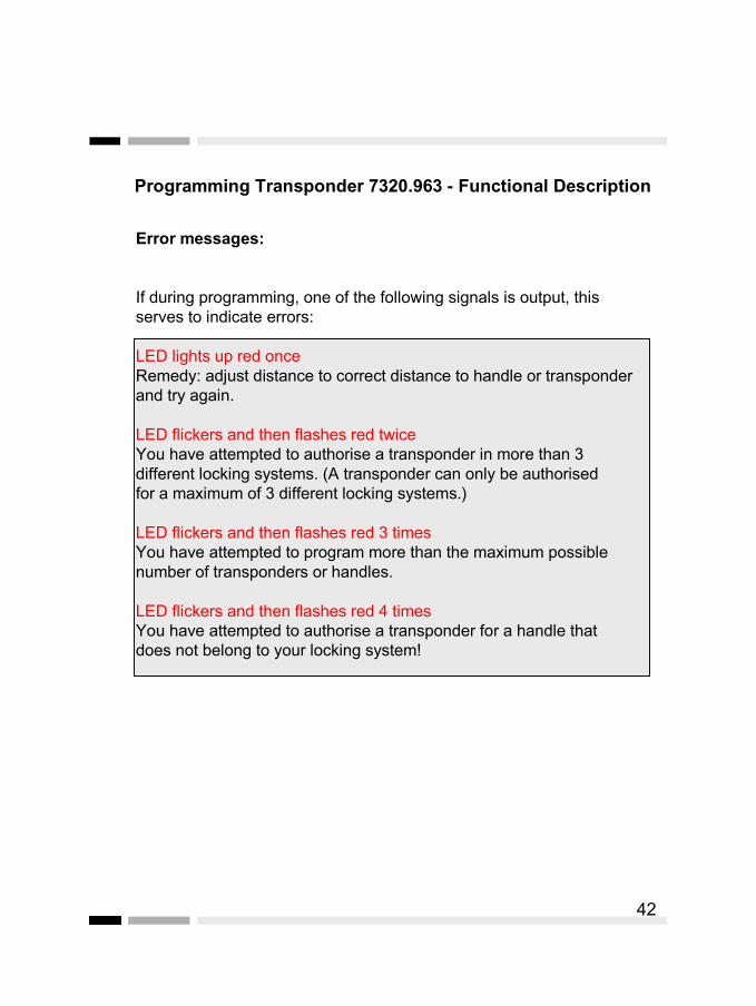
Error messages:
If during programming, one of the following signals is output, thisserves to indicate errors:
LED lights up red onceRemedy: adjust distance to correct distance to handle or transponder and try again.
LED flickers and then flashes red twiceYou have attempted to authorise a transponder in more than 3 different locking systems. (A transponder can only be authorised for a maximum of 3 different locking systems.)
LED flickers and then flashes red 3 timesYou have attempted to program more than the maximum possible number of transponders or handles.
LED flickers and then flashes red 4 timesYou have attempted to authorise a transponder for a handle thatdoes not belong to your locking system!
42

Notes on Maintenance
43
Handle: The contact surface of the push button lock levermust be greased at regular intervals of reasonable length (at least when tight and rough-running).

Technical Specifications Handle
Surface: varnishedMaterial: zinc die-castKey type: transponderMaster key: yesElectronics: SimonsVoss
lock electronics 3061Electrical power supply: SimonsVoss lithium
battery 3.6 Volts½ AA, 900 mAhlithium 3V, CR1220
Battery life: approx. 20,000 – 25,000locking cycles
Retrofit: yesNetwork option: yesTime zone control/access control: optionalAmbient temperature
Operating temperature range: +5°C to +45°CStorage temperature range: -10°C to +50°C
44

EMERGENCY OPENING -Handle
Please contact:
Rittal GmbH & Co. KGAuf dem Stützelberg
D-35745 Herborn
Tel.: ++49 (0) 2772 505 0Tel.: ++49 (0) 2772 505 2578
eMail: [email protected]
For e-mail inquiries, please state the order no. in the subject line.
45