Embed Size (px)
DESCRIPTION
Operating manual for HMI continuous lights
Citation preview

1
Operating instructions HMI 575.800 www.broncolor.com

2
Operating manual b r o n c o l o r HMI 575.800
Before use We are pleased you have chosen a broncolor HMI 575.800 which is a high-quality product in every respect. If used properly, it will render you many years of good service. Please read all the information contained in these operating instructions carefully. They contain important details on the use, safety and maintenance of the appliance. Keep these operating instructions in a safe place and pass them on to further users if necessary. Observe the safety instructions.
Contents page
Important safety instructions 3
Read before starting up the ballast unit 3
Controls and displays 5
Electronic ballast unit HMI 575.800 5
Controls and displays 6
Lamp base HMI F575.800 6
1. Application area HMI 575.800 7
2. Starting up 7
3. Power regulation 8
4. LED displays 9
5. Lamp base HMI F575.800 9
6. Protection 10
7. Protecting glass 11
8. Fuses 11
9. Mounting 11
10. Service/repair 11
11. Operation of broncolor ballast units with motor generators 12
12. Technical data 12
13. Light shaper for HMI F575.800 13
20. Order numbers for diverse accessories and spare parts 14

3
Important safety instructions ! Read before starting up the unit The continuous light source broncolor HMI 575.800 may only be used for the professional illumination of photographic or film scenes and should only be operated by specialized staff. When using your lighting equipment, it is imperative that the safety precautions below are followed precisely: 1. For safety reasons the ballast unit may only be operated with an earthed mains (AC-line)
plug. When the unit is switched on, the yellow LED must light up “earth ok”. 2. Read and understand all instructions before using. 3. The UV radiation content of HMI/MSR light is comparable to that of daylight. The
protecting glass has a filter which reduces the amount of UV to acceptable levels for normal operating distances. When using at a close operating distance unprotected skin may be exposed only for a limited time.
4. Due to the high intensity try to avoid any eye contact with the light source. 5. Close supervision is necessary when any lamp is used near children. Do not leave lamp
unattended while in use. 6. The lamp base and the accessories mounted onto the lamp may heat up to high
temperatures, so please handle with care. 7. Do not operate units with a damaged cable or if they have dropped or damaged – until
they have been examined by a qualified serviceperson. 8. Position the cable so that it will not be tripped over, pulled, or make contact with hot
surfaces. 9. If an extension cable is necessary, a cable with a current rating at least equal to that of
the lamp should be used. Cables rated for less amperage than the appliance may overheat. If using a cable reel, uncoil it completely before use, to avoid overheating of the cable.
10. For safety reasons the lamp base should only be operated with a faultless protection
glass. This provides protection from UV radiation and injuries caused by hot fragments. 11. Do not impede the flow of cooling air circulating through the lamp base and the ballast
unit. During operation the ballast units HMI 575.800 are not stackable. The cooling of the single units would be strongly affected.

4
12. To protect against effects of radiated heat, the lamp base HMI F575.800 must not be pointed at flammable surfaces and/or surfaces sensitive to heat, UV sensitive objects or any living beings from less then 2 meters away. When used at a close-up range, (more than 2m) limit the exposure time of unprotected skin.
13. Always unplug ballast unit and lamp base before cleaning or servicing and when not in
use. Never jerk cable to pull plug from socket. Grasp plug and pull to disconnect. 14. Let ballast unit and lamp base cool completely before storing. When putting away and
winding up cables, ensure that they do not come into contact with hot parts of the units. 15. To reduce risk of electric shock, do not immerse the lamp base or the ballast unit in water
or other liquids. 16. Lamp bases and ballast units are not suitable for application in wet or explosion-hazard
environments. 17. Protect the ballast unit and the lamp base from water and from excessive exposure to
dust. Avoid operating with wet hands. 18. To reduce the risk of electric shock, do not open this appliance, but take it to a qualified
service person when service or repair work is required. Incorrect reassembly can cause electric shock when the appliance is used subsequently.
19. The use of an accessory attachment not recommended by the manufacturer may cause a
risk of fire, electric shock, or injury to persons. 20. In order to prolong the service life of the lamp the heat-up process of approx. 1 minute
should not be interrupted. 21. Prior to replacing fuses, lamp or protecting glass, disconnect the ballast unit from mains
power supply. 22. The ballast unit HMI 575.800 can only be used with the lamp base HMI F575.800.

5
Controls and displays Electronic ballast unit HMI 575.800 1. Mains switch 2. “off“ switch 3. “on“ switch 4. Power regulator (dimmer) 5. LED (green) operation control “on“ 6. LED (red) mains control ”supply ok“ 7. LED (yellow) earth conductor monitoring “earth on“ 8. Lamp plug socket 9. Mains cable socket 10. Fuse 1 11. Fuse 2 12. Grip

6
Controls and displays Lamp base HMI F575.800 1. Mains switch on/off 2. Change-over switch 575 W / 800 W 3. Rotary knob for focusing 4. Locking slider 5. Bayonet connection with automatic locking 6. Counter-reflector screws 7. Daylight lamp 8. Lamp cable 9. Locking lever

7
1. Application area HMI 575.800
The unit has been specially developed for the professional illumination of photographic or film scenes. For countries with an earthed power supply use a 3 pin extension cable.
2. Starting up 2.1 Mains power supply/Voltage selector
Connect ballast unit HMI 575.800 to an earthed mains power supply. It adjusts automatically to the mains (AC-line) voltage applied.
2.2 Earthed power supply
Connect ballast unit HMI 575.800 to the mains supply always with an earthed plug. 2.3 Starting up
The HMI 575.800 is a flicker-free electronic ballast unit which is made for mains voltages from 90 V to 265 V. It adjusts automatically to the mains (AC-line) voltage applied. The unit is suited to operate with lamp bases with a hot restrike (HR), which means that the lamp may be switched on again at any time while hot, making waiting time unnecessary. For safety reasons, the high ignition voltages required for this purpose must have a faultless earth conductor, the function of which can be checked with the aid of the earth monitoring lamp “earth ok” (7). For this reason the ballast unit must always be connected to the power supply with an earthed mains plug. 1.) Adjust, with a coin or a screw driver, the desired power level with the change-over
switch (2) of the lamp base HMI F575.800, to either 575 W or 800 W. 2.) Equip the lamp base with a daylight lamp of the the corresponding power level (7)
and latch on the protection glass. Attention: If the lamp base HMI F575.800 is set to the power level 800 W and
by mistake is equipped with a 575 W lamp, the lamp will become damaged. Furthermore there is the danger that the lamp will explode.
3.) Connect the lamp base with the lamp base cable to the ballast unit and the mains
supply cable of the ballast unit to the earthed mains (AC-line). 4.) Switch on the mains switch (1) of the lamp base (position “on”).

8
5.) Switch on the mains (AC-line) switch (1) on the ballast unit and check, whether the yellow LED of the earth monitoring lamp „earth ok“ (7) as well as the red LED “supply ok” of the mains control light up continuously. Under these conditions the ballast unit is in operation. The green LED “on” (5) of the operation control lights up. If the mains (AC-line) switch (1) of the lamp base is „on“, the lamp will light up.
6.) If the yellow LED „earth ok“ (7) does not light up, for safety reasons disconnect immediately disconnect the ballast unit from the mains (AC-line) supply and control the earth line. It is not possible to switch on if the red LED “supply ok” is blinking, it means a technical fault has been detected (see chapter 4: LED displays).
7.) The optimal colour temperature of the lamp is reached after approx. 3 minutes of operation. The ballast unit HMI 575.800 is equipped with an automatic heat-up device, so that the operating temperature is reached after only 1 minute. In this period the unit should only be switched off if absolutely necessary in order to prolong the service life of the lamp. The heat-up process should always be carried out on full power. Attention: If the HMI/MSR lamp cannot be triggered, the ballast unit stops the
trigger process after about 1.5 s. A new attempt to trigger can be initiated by first pressing the red “off” (2) and then the green “on” (3) keys. After 10 attempts the unit will block the trigger circuit for about 30 seconds. After that further attempts are possible.
8.) Ensure that the ventilation slots of the ballast unit and the lamp base are
unobstructed during operation. By pressing the red “off” (2) key on the ballast unit, the lamp will switch off. By pressing the red “on” (3) key, the unit will operate again.
3. Power regulation
The required light output can be set with the power regulator (4). The adjustment range extends from 60% - 100% and is equivalent to approximately 1 f-stop. It should be noted that the colour temperature can change with the power output depending on the type of lamp used. During heat-up the dimmer is blocked and the power is automatically set to full until the operating temperature is achieved. The blocking time of the dimmer depends on the lamp temperature when switching on and can vary between 5 s and 40 s.

9
4. LED displays 4.1 Green LED “on“
If the ballast unit HMI 575.800 is in operation, the green LED „on“ for the operation control (5) must continuously light up. If the green LED flashes, the temperature control is activated and regulates slowly the power down to 60%. The lowering of power allows the user, to perceive the critical temperature value and delays so the switch off the unit (see chapter 6.2: thermo protection).
4.2 Red LED “supply ok“ If the ballast unit HMI 575.800 is in operation, the red LED “supply ok“ for the mains control (6) must continuously light up. If the red LED flashes the unit has shut down due to one of the following reasons: a) The mains voltage has dropped below 85 V b) Overload protection of the ignition device: To protect the ignition device, it will be
blocked for about 30 seconds after 10 ignition trials in series . c) Overheating of the ballast unit d) Short-circuit in the ballast unit and/or in the lamp base e) Technical failure If the red LED flashes, the ballast unit switches off automatically. For safety reasons, the unit does not switch on automatically, when the technical failure is resolved and it has returned to normal operation mode (red LED lights up continuously. The lamp must be switched on again manually.
4.3 Yellow LED “earth ok“ If the ballast unit HMI 575.800 is in operation, the yellow LED “earth ok“ for the earth conductor monitoring (7) must continuously light up. If the yellow LED „earth ok“ (7) does not light up, for safety reasons, immediately disconnect the ballast unit from the mains (AC-line) supply and control the earth line. Ballast units and lamp bases of the protection class may only be used with a fully-operational earth line.
5. Lamp base HMI F575.800
The lamp base HMI F575.800 can be equipped optionally with a daylight lamp of power level 575 W or 800 W . Attention: Adjust beforehand with a coin or a screw driver, the desired power level
with the change-over switch (2) of the lamp base HMI F575.800, to either 575 W or 800 W.

10
5.1 Daylight lamp The daylight lamp used, operates at a high internal pressure and can explode if used beyond its service life. The lamp should therefore be exchanged before it reaches the maximum hours of indicated operation by the lamp manufacturer.
5.2 Protecting glass The corresponding protecting glass must be used categorically to protect from lamp explosion and UV-radiation. The lamp base HMI F575.800 is provided with a circuit breaker. Therefore the unit cannot be switched on without a protecting glass. The UV- coated protecting glass is also available in a matt version.
5.3 Exchanging lamp Before replacing the lamp always disconnect the lamp base from the ballast unit! Attention: Hot lamp !!! After removing the protecting glass the counter reflector screws (6) must be loosened to be able to remove the counter reflector over the lamp. Now the lamp can be replaced and the counter reflector and the protecting glass can be remounted.
6. Protection 6.1 Fan cooling
A low-noised fan cools the lamp base. When the mains supply (1) is switched off, the fan rotates at a higher speed, to guarantee faster cooling.
6.2 Thermo-protection
If the ballast unit HMI 575.800 is in operation, the green LED „on“ for the operation control (5) must continuously light up. If the green LED flashes, the temperature control is activated and regulates slowly the power down to 60%. If the ballast unit reaches the predefined limit of overheating, the red LED “supply ok” of the mains control (6) starts to flash and the ballast unit switches off automatically. For safety reasons the unit does not switch on automatically when the technical failure is resolved and it has returned to the normal operation mode (red LED lights up continuously). The lamp must be switched on again manually. The lamp base HMI F575.800 is also equipped with a thermo-protection and switches off automatically if overheating (the cooling fan continues to rotate at a higher speed). In this case the lamp base must be switched off manually, with the mains switch (1), to avoid, that it automatically switches on again after the cooling process.

11
7. Protecting glass
For safety reasons the lamp base HMI F575.800 can only be operated with a mounted protecting glass and is equipped with a circuit breaker. Therefore the unit cannot be switched on without a protecting glass. The UV-coated protecting glass is also available in a matt version.
8. Fuses
The fuses (10 and 11) are located on the operating side of the ballast unit HMI 575.800. Use exclusively sand filled fuses with the value 10 AT. The use of wrong fuses can cause extensive damage to the ballast unit or lamp base.
9. Mounting
The stand adapter is located underneath the housing. It allows the insertion of 12 mm (broncolor®) or 16 mm bolts. When operating make sure that the unit is securely fixed on the stand. By pulling out the stop lever it can adjusted in its notches.
10. Service/repair
Your broncolor daylight source is a precision unit. If you take good care, it will work trouble-free for many years. However, if you should have any failures, please, do not try to open the unit to repair it yourself. Even if the unit is switched off, dangerous voltages can remain within the unit. Therefore, always leave servicing and repairs to a broncolor service agency.
12
11. Operation of broncolor ballast units with motor generators broncolor ballast units are suitable for operation with motor generators, provided that their voltage under all charge conditions (including capacity charge) remains within the tolerance limit of 90 - 265V. According to experience, it is necessary that only electronic stabilized motor generators are used.
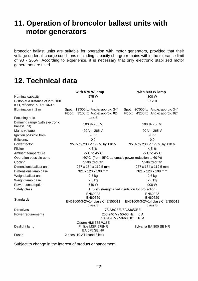
12. Technical data
with 575 W lamp with 800 W lamp Nominal capacity 575 W 800 W F-stop at a distance of 2 m, 100 ISO, reflector P70 at 1/60 s
8 8 5/10
Illumination in 2 m Spot: 13’000 lx Angle: approx. 34° Flood: 3’100 lx Angle: approx. 82°
Spot: 20’000 lx Angle: approx. 34° Flood: 4’200 lx Angle: approx. 82°
Focusing ratio 1: 4,5 Dimming range (with electronic ballast unit) 100 % - 60 % 100 % - 60 %
Mains voltage 90 V – 265 V 90 V – 265 V Ignition possible from 90 V 90 V Efficiency 0.9 0.9 Power factor 95 % by 230 V / 99 % by 110 V 95 % by 230 V / 99 % by 110 V Flicker < 5 % < 5 % Ambient temperature -5°C to 45°C -5°C to 45°C Operation possible up to 60°C (from 45°C automatic power reduction to 60 %) Cooling Stabilized fan Stabilized fan Dimensions ballast unit 267 x 184 x 112,5 mm 267 x 184 x 112,5 mm Dimensions lamp base 321 x 120 x 198 mm 321 x 120 x 198 mm Weight ballast unit 2,6 kg 2,6 kg Weight lamp base 2,6 kg 2,6 kg Power consumption 640 W 900 W Safety class I (with strengthened insulation for protection)
Standards
EN60922 EN60529
EN61000-3-2/A14 class C, EN55011 class B
EN60922 EN60529
EN61000-3-2/A14 class C, EN55011 class B
Directives 73/23/CEE, 89/336/CEE Power requirements 200-240 V / 50-60 Hz: 6 A
100-120 V / 50-60 Hz: 10 A
Daylight lamp Osram HMI 575 W/SE Philips MSR 575HR
BA 575 SE HR Sylvania BA 800 SE HR
Fuses 2 pces, 10 AT (sand-filled) Subject to change in the interest of product enhancement.

13
13. Light shaper for HMI F575.800
The lamp base HMI F575.800 is equipped with a Pulso bayonet mount. Therefore the light shapers from the broncolor range listed below are available for light control and light shaping design. The accessory used in front of the lamp base HMI F575.800 becomes very hot, which requires more precaution and consideration, when using one of the below listed articles. Under some articles you will find the corresponding restrictions for use. Standard reflector P70 Article no. 33.107.00
Standard reflector P65 Article no. 33.106.00
Narrow angle reflector P45 Article no. 33.104.00
Narrow angle reflector P50 Article no. 33.105.00
Wide angle reflector P120 Article no. 33.112.00
Reflector P-Travel Article no. 33.103.00
Reflector PAR Article no. 33.113.00
Reflector Satellite Staro Article no. 33.151.00 For thermal reasons, only use without Plexi-diffusor
Reflector Satellite Evolution Article no. 33.150.00
Reflector Mini-Satellite Article no. 33.152.00
Special reflectors Para / Para FF / Para FB various article numbers
Softbox Pulsoflex EM 80 x 80 cm Article no. 33.407.00 Only use with adapter ring with integrated reflector (Art. no. 43.100.00)
Softbox Pulsoflex EM 110 x 110 cm Article no. 33.408.00 Only use with adapter ring with integrated reflector (Art. no. 43.100.00)
Softbox Pulsoflex EM 80 x 140 cm Article no. 33.417.00 Only use with adapter ring with integrated reflector (Art. no. 43.100.00)
Softbox Pulsoflex C 100 x 100 cm Article no. 33.442.00 Only use with adapter ring with integrated reflector (Art. no. 43.100.00)
Softbox Pulsoflex C 150 x 150 cm Article no. 33.445.00 Only use with adapter ring with integrated reflector (Art .no. 43.100.00)
Softbox Pulsoflex C 80 x 140 cm Article no. 33.446.00 Only use with adapter ring with integrated reflector (Art. no. 43.100.00)
Area light Balloon The lamp base broncolor HMI F575.800 (art. no. 42.104.00) must be equipped with the HMI 575 W/SE lamp (art. no. 44.100.00) Article no. 33.161.00
Area light Mini-Cumulite Article no. 33.141.00 For thermal reasons the glass counter-reflector (33.301.00) may not be used
Area light Hazylight Soft Article no. 33.513.00 For thermal reasons the glass counter-reflector (33.301.00) may not be used

14
Area light Megaflex Article no. 33.521.00
Area light Cumulite 2 Article no. 33.534.00
Area light Megalite (14 different sizes) Article no. 33.540.XX Article no. 33.541.XX
For thermal reasons, the following light shapers may not be used : Conical snoot Article no. 33.120.00
Fresnel spot attachment Article no. 33.630.00
Spot attachment Article no. 33.640.00
All honeycomb grids for all metal reflectors various article numbers
All umbrellas Ø 82 cm and Ø 102 cm various article numbers
Reflector Mini-Hazylight Article no. 33.133.00
Area light Hazylight 2 Article no. 33.511.00
20. Order numbers for diverse accessories and spare parts
Parabolic reflector for HMI F575.800 with 4 lenses (5500 K) Article no. 43.103.55 Parabolic reflector for HMI F575.800 with 4 lenses (5900 K) Article no. 43.103.59 Lamp HMI 575 W/SE for lamp base HMI F575.800 Article no. 44.100.00 Lamp BA 800 SE HR for lamp base HMI F575.800 Article no. 44.104.00 Protecting glass (5500 K) for lamp base HMI F575.800 Article no. 44.101.55 Protecting glass (5500 K), matt, for lamp base HMI F575.800 Article no. 44.102.55 Adapter ring for Pulsoflex C/EM with lamp base HMI F575.800 Article no. 43.100.00 Reflector for Pulso-Flooter S with lamp base HMI F575.800 Article no. 43.101.00 Lamp extension cable, 7.5 m, for HMI 575.800 Article no. 44.200.00 Mains cable EU, black Article no. L6884.00 Mains cable CH, black Article no. L3255.01 Mains cable USA, black Article no. L6884.01 Fuse 10 AT / 5 x 20 mm G Article no. 30908.00 Transport protection cap, grey, for lamp base HMI F575.800 Article no. Z5917.00