Embed Size (px)
Citation preview

GSM-2 Operating-Manual
- 1 –
Operating Manual GSM-2
Version 1.00 – February 2009
Date: 10.02.2009 c:\Daten\Word\Manual_GSM-V2.70_E.doc
GSM-2 Operating-Manual
- 2 –
Content 1.1 GSM-2 Overview ..............................................................................................................................................................4 1.2 GSM-2 features and advantages:.....................................................................................................................................4
2 General description / GSM-2 Communication .................................................................................................................5 2.1 GSM DataManager...........................................................................................................................................................5 2.2 Data transfer.....................................................................................................................................................................5 2.3 Configuration ....................................................................................................................................................................5 2.4 Measurement / Data logging ............................................................................................................................................6 2.5 Power management .........................................................................................................................................................6
3 Minimum equipment for GSM-Data-Logging ...................................................................................................................6
4 GSM-2 Harware ...................................................................................................................................................................7 4.1 GSM-2 housing.................................................................................................................................................................7 4.2 GSM-2 accessories (delivered with GSM-2) ....................................................................................................................7 4.3 How to open and close the GSM-2 housing .....................................................................................................................8 4.4 The inside of GSM-2.........................................................................................................................................................9 4.5 Insert or release the SIM-card ..........................................................................................................................................9 4.6 Connect / exchange Battery ...........................................................................................................................................10 4.7 Antenna connection........................................................................................................................................................10 4.8 Adapter socket / level sensor connection ....................................................................................................................11
5 Lock-Unit ...........................................................................................................................................................................12
6 Battery lifetime..................................................................................................................................................................12
7 Connection / Plug .............................................................................................................................................................13 7.1 Pin-Table ........................................................................................................................................................................13 7.2 Supply.............................................................................................................................................................................13 7.3 RS 485............................................................................................................................................................................13 7.4 Voltage Input ..................................................................................................................................................................13 7.5 Switch input ....................................................................................................................................................................14 7.6 SDI12 communication interface......................................................................................................................................14
8 Installation at a measuring point with Lock-Unit...........................................................................................................15
9 GSM Setup description ....................................................................................................................................................17 9.1 Overview.........................................................................................................................................................................17 9.2 Next Action / Interval ......................................................................................................................................................18 9.3 Settings...........................................................................................................................................................................19 9.4 Measure..........................................................................................................................................................................21 9.5 GPRS settings................................................................................................................................................................22 9.6 Location info and water level configuration ....................................................................................................................23 9.7 Error / State ....................................................................................................................................................................24 9.8 Check E-Mail / SMS .......................................................................................................................................................25 9.9 Alarm ..............................................................................................................................................................................26 9.10 Info .................................................................................................................................................................................27 9.11 Data connection..............................................................................................................................................................28
10 Message format ............................................................................................................................................................29 10.1 E-Mail .............................................................................................................................................................................29 10.2 SMS................................................................................................................................................................................30
GSM-2 Operating-Manual
- 3 –
11 Data connection............................................................................................................................................................31 11.1 Using “Modem Reader” for automatic read-out ..............................................................................................................31
12 E-Mail configuration.....................................................................................................................................................32 12.1 1 E-Mail account for outgoing and incoming messages ................................................................................................32 12.2 2 E-mail accounts one for outgoing and one for incoming messages ............................................................................32 12.3 many E-mail accounts one for outgoing and one for each GSM-2 for incoming messages ...........................................33
13 APN / GPRS-Settings for different providers.............................................................................................................34
14 First installation step by step......................................................................................................................................36 14.1 connect level sensor.......................................................................................................................................................36 14.2 insert SIM card ...............................................................................................................................................................36 14.3 insert Battery ..................................................................................................................................................................36 14.4 close the GSM-2 housing and connect antenna.............................................................................................................37 14.5 insert GSM-2 in to the measuring point and connect to PC............................................................................................37 14.6 configure the GSM-2 with GSM Setup program .............................................................................................................38 14.7 General settings .............................................................................................................................................................38 14.8 Check time and interval ..................................................................................................................................................38 14.9 Measure interval and E-Mail send time ..........................................................................................................................39 14.10 GPRS and E-Mail box settings...................................................................................................................................39 14.11 send configuration E-Mail...........................................................................................................................................40
GSM-2 Operating-Manual
- 4 –
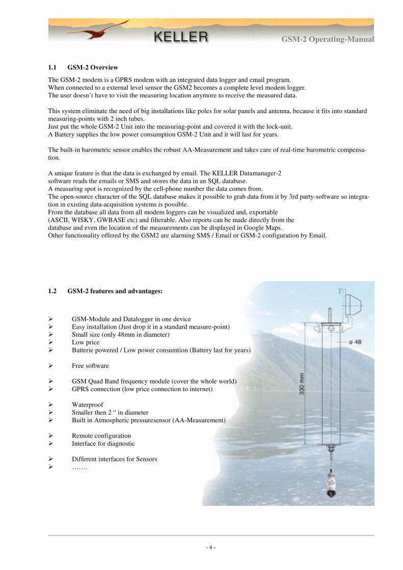
1.1 GSM-2 Overview
The GSM-2 modem is a GPRS modem with an integrated data logger and email program.
When connected to a external level sensor the GSM2 becomes a complete level modem logger.
The user doesn’t have to visit the measuring location anymore to receive the measured data.
This system eliminate the need of big installations like poles for solar panels and antenna, because it fits into standard
measuring-points with 2 inch tubes.
Just put the whole GSM-2 Unit into the measuring-point and covered it with the lock-unit.
A Battery supplies the low power consumption GSM-2 Unit and it will last for years.
The built-in barometric sensor enables the robust AA-Measurement and takes care of real-time barometric compensa-
tion.
A unique feature is that the data is exchanged by email. The KELLER Datamanager-2
software reads the emails or SMS and stores the data in an SQL database.
A measuring spot is recognized by the cell-phone number the data comes from.
The open-source character of the SQL database makes it possible to grab data from it by 3rd party-software so integra-
tion in existing data-acquisition systems is possible.
From the database all data from all modem loggers can be visualized and, exportable
(ASCII, WISKY, GWBASE etc) and filterable. Also reports can be made directly from the
database and even the location of the measurements can be displayed in Google Maps.
Other functionality offered by the GSM2 are alarming SMS / Email or GSM-2 configuration by Email.
1.2 GSM-2 features and advantages:
� GSM-Module and Datalogger in one device
� Easy installation (Just drop it in a standard measure-point)
� Small size (only 48mm in diameter)
� Low price
� Batterie powered / Low power consumtion (Battery last for years)
� Free software
� GSM Quad Band frequency module (cover the whole world)
� GPRS connection (low price connection to internet)
� Waterproof
� Smaller then 2 “ in diameter
� Built in Atmospheric pressuresensor (AA-Measurement)
� Remote configuration
� Interface for diagnostic
� Different interfaces for Sensors
� …….
GSM-2 Operating-Manual
- 5 –
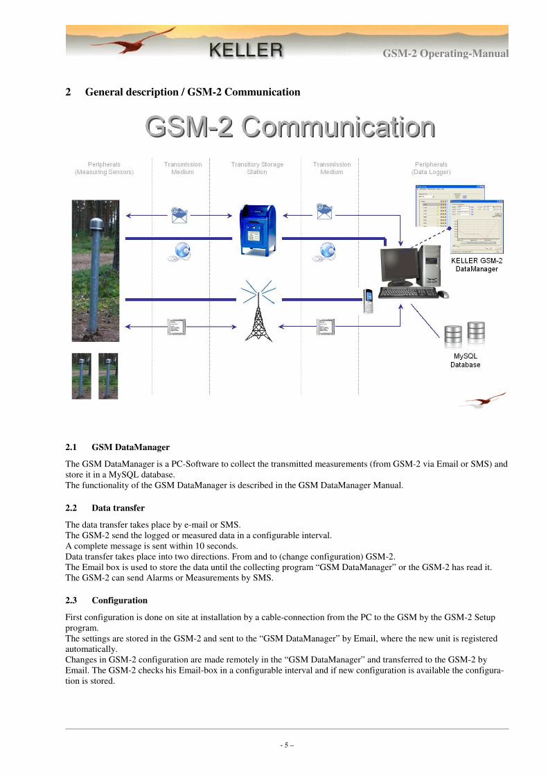
2 General description / GSM-2 Communication
2.1 GSM DataManager
The GSM DataManager is a PC-Software to collect the transmitted measurements (from GSM-2 via Email or SMS) and
store it in a MySQL database.
The functionality of the GSM DataManager is described in the GSM DataManager Manual.
2.2 Data transfer
The data transfer takes place by e-mail or SMS.
The GSM-2 send the logged or measured data in a configurable interval.
A complete message is sent within 10 seconds.
Data transfer takes place into two directions. From and to (change configuration) GSM-2.
The Email box is used to store the data until the collecting program “GSM DataManager” or the GSM-2 has read it.
The GSM-2 can send Alarms or Measurements by SMS.
2.3 Configuration
First configuration is done on site at installation by a cable-connection from the PC to the GSM by the GSM-2 Setup
program.
The settings are stored in the GSM-2 and sent to the “GSM DataManager” by Email, where the new unit is registered
automatically.
Changes in GSM-2 configuration are made remotely in the “GSM DataManager” and transferred to the GSM-2 by
Email. The GSM-2 checks his Email-box in a configurable interval and if new configuration is available the configura-
tion is stored.
GSM-2 Operating-Manual
- 6 –
2.4 Measurement / Data logging
The GSM-2 measures in a configurable interval all sensors/channels and stores it in a EEPROM.
After a configurable amount of stored data, the data-transfer takes place.
Alarm functions are configurable and messages are sent immediately if alarm condition is true.
2.5 Power management
The unit is in a sleep mode only the real-time clock is active.
For measurement, the supply of the sensors are switched on for a short time (~5 seconds) and after the measurement is
done, the measurements are stored and the supply is switched off.
To send a message, the GSM-Module is powered on and within a few seconds, the messages are sent.
This is the most power consumption task. But due to the battery with high quality/capacity and low self discharge, the
battery will last for many years.
For Example, if you measure every minute and send data once per day, the battery last for >10 Years.
3 Minimum equipment for GSM-Data-Logging
To run a data-logging-system you need at least:
� GSM-2 Unit including Water-level-sensor
� SIM-card
� PC with GSM DataManager Software and MySQL database and internet connection
� One Email account (accessible from GSM-Network via SMTP/POP)
GSM-2 Operating-Manual
- 7 –
4 GSM-2 Harware
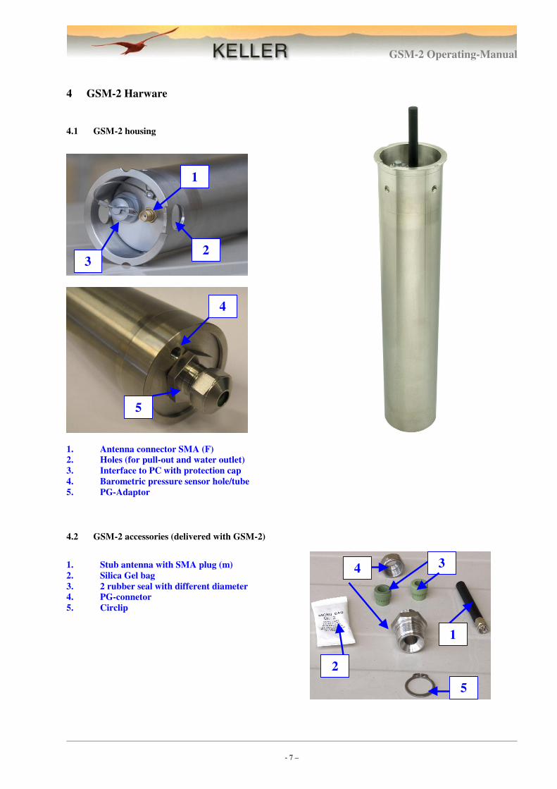
4.1 GSM-2 housing
1. Antenna connector SMA (F)
2. Holes (for pull-out and water outlet)
3. Interface to PC with protection cap
4. Barometric pressure sensor hole/tube
5. PG-Adaptor
4.2 GSM-2 accessories (delivered with GSM-2)
1. Stub antenna with SMA plug (m)
2. Silica Gel bag
3. 2 rubber seal with different diameter
4. PG-connetor
5. Circlip
4
5
1
2 3
2
5
1
4 3
GSM-2 Operating-Manual
- 8 –
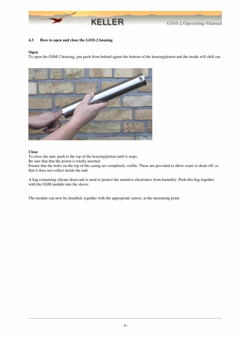
4.3 How to open and close the GSM-2 housing
Open To open the GSM-2 housing, just push from behind aginst the bottom of the housing/piston and the inside will shift out.
Close
To close the unit, push to the top of the housing/piston until it stops.
Be sure that that the piston is totally inserted.
Ensure that the holes on the top of the casing are completely visible. These are provided to allow water to drain off, so
that it does not collect inside the unit.
A bag containing silicate desiccant is used to protect the sensitive electronics from humidity. Push this bag together
with the GSM module into the sleeve.
The module can now be installed, together with the appropriate sensor, at the measuring point.
GSM-2 Operating-Manual
- 9 –
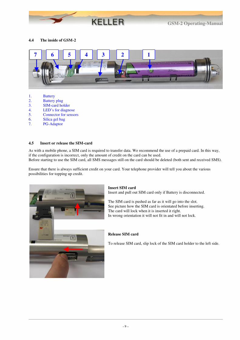
4.4 The inside of GSM-2
1. Battery
2. Battery plug
3. SIM-card holder
4. LED’s for diagnose
5. Connector for sensors
6. Silica gel bag
7. PG-Adaptor
4.5 Insert or release the SIM-card
As with a mobile phone, a SIM card is required to transfer data. We recommend the use of a prepaid card. In this way,
if the configuration is incorrect, only the amount of credit on the card can be used.
Before starting to use the SIM card, all SMS messages still on the card should be deleted (both sent and received SMS).
Ensure that there is always sufficient credit on your card. Your telephone provider will tell you about the various
possibilities for topping up credit.
Insert SIM card
Insert and pull out SIM card only if Battery is disconnected.
The SIM card is pushed as far as it will go into the slot.
See picture how the SIM card is orientated before inserting.
The card will lock when it is inserted it right.
In wrong orientation it will not fit in and will not lock.
Release SIM card
To release SIM card, slip lock of the SIM card holder to the left side.
1 6 7 5 4 2 3
GSM-2 Operating-Manual
- 10 –
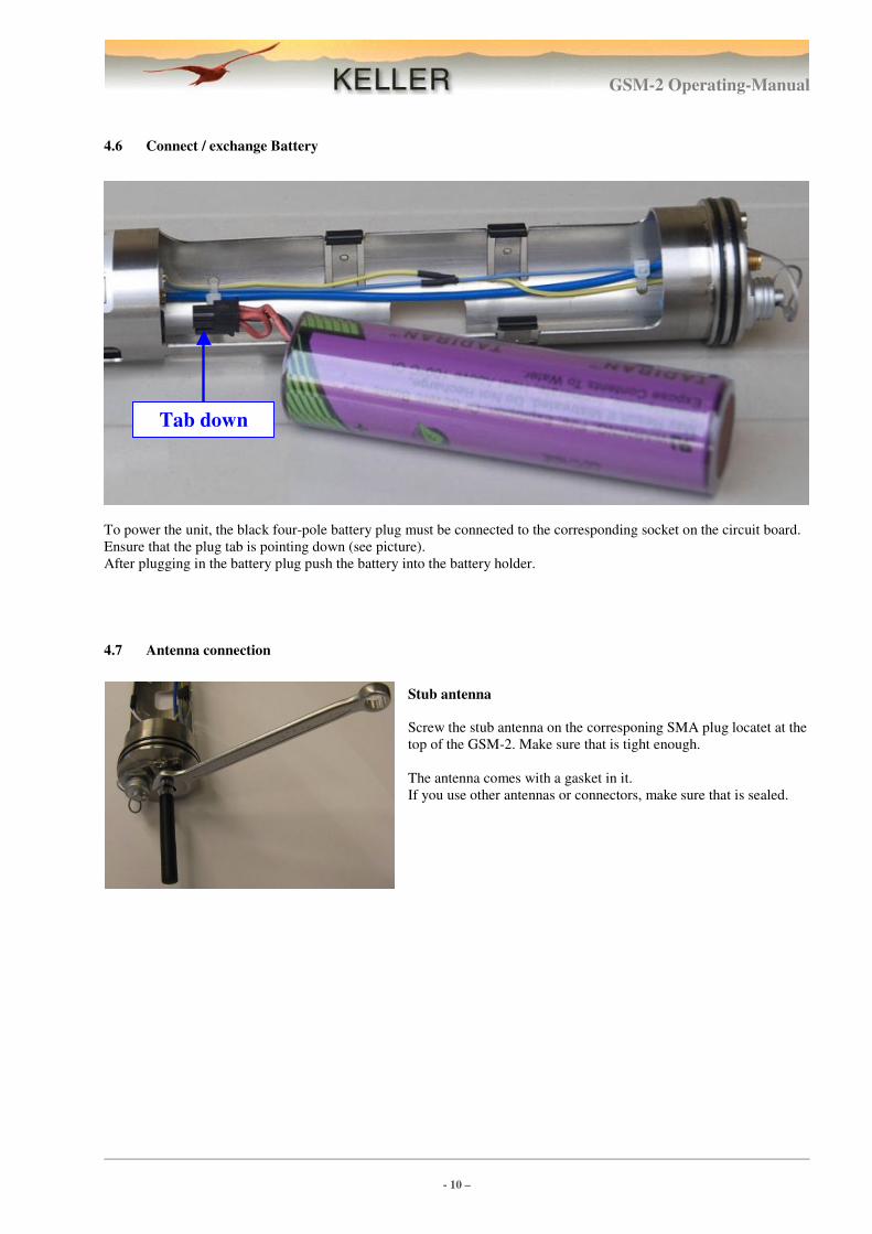
4.6 Connect / exchange Battery
To power the unit, the black four-pole battery plug must be connected to the corresponding socket on the circuit board.
Ensure that the plug tab is pointing down (see picture).
After plugging in the battery plug push the battery into the battery holder.
4.7 Antenna connection
Stub antenna
Screw the stub antenna on the corresponing SMA plug locatet at the
top of the GSM-2. Make sure that is tight enough.
The antenna comes with a gasket in it.
If you use other antennas or connectors, make sure that is sealed.
Tab down
GSM-2 Operating-Manual
- 11 –
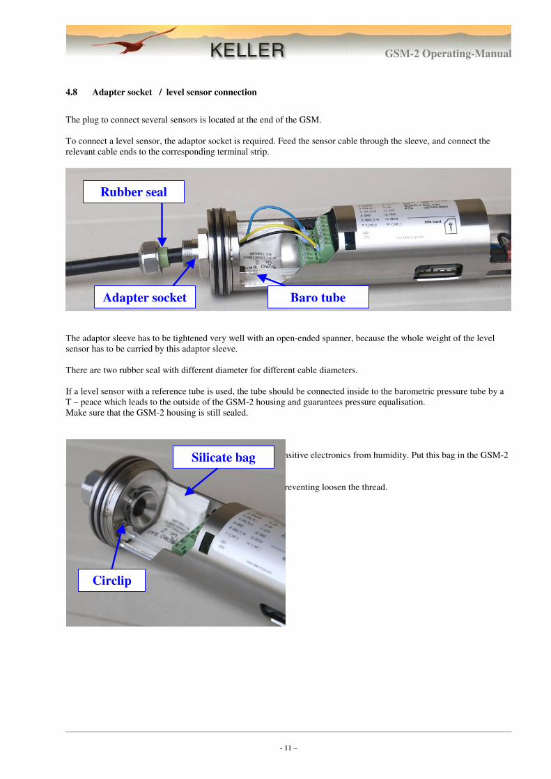
4.8 Adapter socket / level sensor connection
The plug to connect several sensors is located at the end of the GSM.
To connect a level sensor, the adaptor socket is required. Feed the sensor cable through the sleeve, and connect the
relevant cable ends to the corresponding terminal strip.
The adaptor sleeve has to be tightened very well with an open-ended spanner, because the whole weight of the level
sensor has to be carried by this adaptor sleeve.
There are two rubber seal with different diameter for different cable diameters.
If a level sensor with a reference tube is used, the tube should be connected inside to the barometric pressure tube by a
T – peace which leads to the outside of the GSM-2 housing and guarantees pressure equalisation.
Make sure that the GSM-2 housing is still sealed.
A bag containing silicate desiccant is used to protect the sensitive electronics from humidity. Put this bag in the GSM-2
housing like you can see it in the picture.
The circlip is mounted at the inside of the adapter socket, preventing loosen the thread.
Circlip
Silicate bag
Rubber seal
Adapter socket Baro tube
GSM-2 Operating-Manual
- 12 –
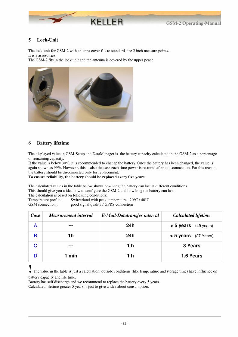
5 Lock-Unit
The lock-unit for GSM-2 with antenna cover fits to standard size 2 inch measure points.
It is a assesoiries.
The GSM-2 fits in the lock unit and the antenna is covered by the upper peace.
6 Battery lifetime
The displayed value in GSM-Setup and DataManager is the battery capacity calculated in the GSM-2 as a percentage
of remaining capacity.
If the value is below 30%, it is recommended to change the battery. Once the battery has been changed, the value is
again shown as 99%. However, this is also the case each time power is restored after a disconnection. For this reason,
the battery should be disconnected only for replacement.
To ensure reliability, the battery should be replaced every five years.
The calculated values in the table below shows how long the battery can last at different conditions.
This should give you a idea how to configure the GSM-2 and how long the battery can last.
The calculation is based on following conditions:
Temperature profile : Switzerland with peak temperature –20°C / 40°C
GSM connection : good signal quality / GPRS connection
Case Measurement interval E-Mail-Datatransfer interval Calculated lifetime
A --- 24h > 5 years (49 years)
B 1h 24h > 5 years (27 Years)
C --- 1 h 3 Years
D 1 min 1 h 1.6 Years
! The value in the table is just a calculation, outside conditions (like temperature and storage time) have influence on
battery capacity and life time.
Battery has self discharge and we recommend to replace the battery every 5 years.
Calculated lifetime greater 5 years is just to give a idea about consumption.
GSM-2 Operating-Manual
- 13 –
7 Connection / Plug
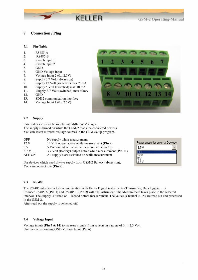
7.1 Pin-Table
1. RS485-A
2. RS485-B
3. Switch input 1
4. Switch input 2
5. GND
6. GND Voltage Input
7. Voltage Input 2 (0…2.5V)
8. Supply 3,7 Volt (always on)
9. Supply 12 Volt (switched) max 20mA
10. Supply 5 Volt (switched) max 10 mA
11. Supply 3.7 Volt (switched) max 60mA
12. GND
13. SDI12 communication interface
14. Voltage Input 1 (0…2.5V)
7.2 Supply
External devices can be supply with different Voltages.
The supply is turned on while the GSM-2 reads the connected devices.
You can select different voltage sources in the GSM-Setup program.
OFF No supply while measurement
12 V 12 Volt output active while measurement (Pin 9)
5 V 5 Volt output active while measurement (Pin 10)
3.7 V 3.7 Volt (Battery) output active while measurement (Pin 11)
ALL ON All supply’s are switched on while measurement
For devices which need always supply from GSM-2 Battery (always on),
You can connect it to (Pin 8).
7.3 RS 485
The RS 485 interface is for communication with Keller Digital instruments (Transmitter, Data loggers, …).
Connect RS485 A (Pin 1) and RS 485 B (Pin 2) with the instrument. The Measurement takes place in the selected
interval. The Supply is turned on 1 second before measurement. The values (Channel 0…5) are read out and processed
in the GSM-2.
After read out the supply is switched off.
7.4 Voltage Input
Voltage inputs (Pin 7 & 14) to measure signals from sensors in a range of 0 … 2,5 Volt.
Use the corresponding GND Voltage Input (Pin 6)
1 2 3 4 5 6 7
8 9 10 11 12 13 14
GSM-2 Operating-Manual
- 14 –
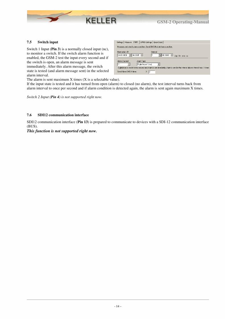
7.5 Switch input
Switch 1 Input (Pin 3) is a normally closed input (nc),
to monitor a switch. If the switch alarm function is
enabled, the GSM-2 test the input every second and if
the switch is open, an alarm message is sent
immediately. After this alarm message, the switch
state is tested (and alarm message sent) in the selected
alarm interval.
The alarm is sent maximum X times (X is a selectable value).
If the input state is tested and it has turned from open (alarm) to closed (no alarm), the test interval turns back from
alarm interval to once per second and if alarm condition is detected again, the alarm is sent again maximum X times.
Switch 2 Input (Pin 4) is not supported right now.
7.6 SDI12 communication interface
SDI12 communication interface (Pin 13) is prepared to communicate to devices with a SDI-12 communication interface
(BUS).
This function is not supported right now.

GSM-2 Operating-Manual
- 15 –
8 Installation at a measuring point with Lock-Unit
1. Attach this Lock-Unit at the measuring point.
The Lock-Unit with a antenna protection cap mounted at the upper part
is suitable for 2 inch standard pipes.
2. Note all needed installation data
� Measure actual water level by hand
� Network name , Location name
� Location position (Longitude , Latitude , Altitude
� Height of Wellhead above sea level
� Installation depth of level sensor
This installation data is tipped in the GSM-Setup software and later
transferred to the GSM-DataManager.
2. Insert the GSM –2
The module can now be installed, together with the appropriate sensor, at
the measuring point.
3. Configure the GSM-2 with GSM-Setup program
Connect the GSM-2 to the PC and configure it with the GSM-Setup pro-
gram.
The configuration is sent by e-mail to the GSM-2 Datamanger, where the
location is registered automatically.
Make sure that e-mail is sent without error, check signal quality and actual
measured values.
GSM-2 Operating-Manual
- 16 –
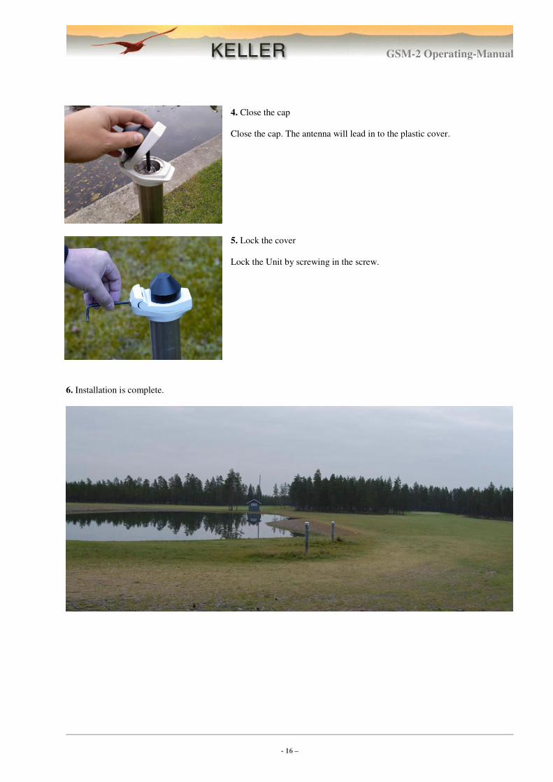
4. Close the cap
Close the cap. The antenna will lead in to the plastic cover.
5. Lock the cover
Lock the Unit by screwing in the screw.
6. Installation is complete.
GSM-2 Operating-Manual
- 17 –
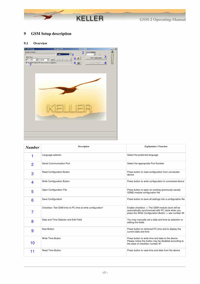
9 GSM Setup description
9.1 Overview
Number Description Explanation / Function
1 Language selector Select the preferred language
2 Serial Communication Port Select the appropriate Port Number
3 Read Configuration Button Press button to read configuration from connected
device
4 Write Configuration Button Press button to write configuration to connected device
5 Open Configuration File Press button to open an existing (previously saved)
GSM2 module configuration file
6 Save Configuration Press button to save all settings into a configuration file
7
Checkbox “Set GSM time to PC time at write configuration” Enable checkbox -> The GSM module clock will be automatically synchronized with PC clock when you press the Write Configuration Button -> see number #4
8 Date and Time Selector and Edit Field You may manually set a date and time by selection or
editing the fields
9 Now Button Press button to retrieved PC time and to display the
current date and time
10
Write Time Button Press button to write time and date to the device. Please notice the button may be disabled according to the state of checkbox number #7
11 Read Time Button Press button to read time and date from the device
7
2
3
4
5
6
1
GSM-2 Operating-Manual
- 18 –
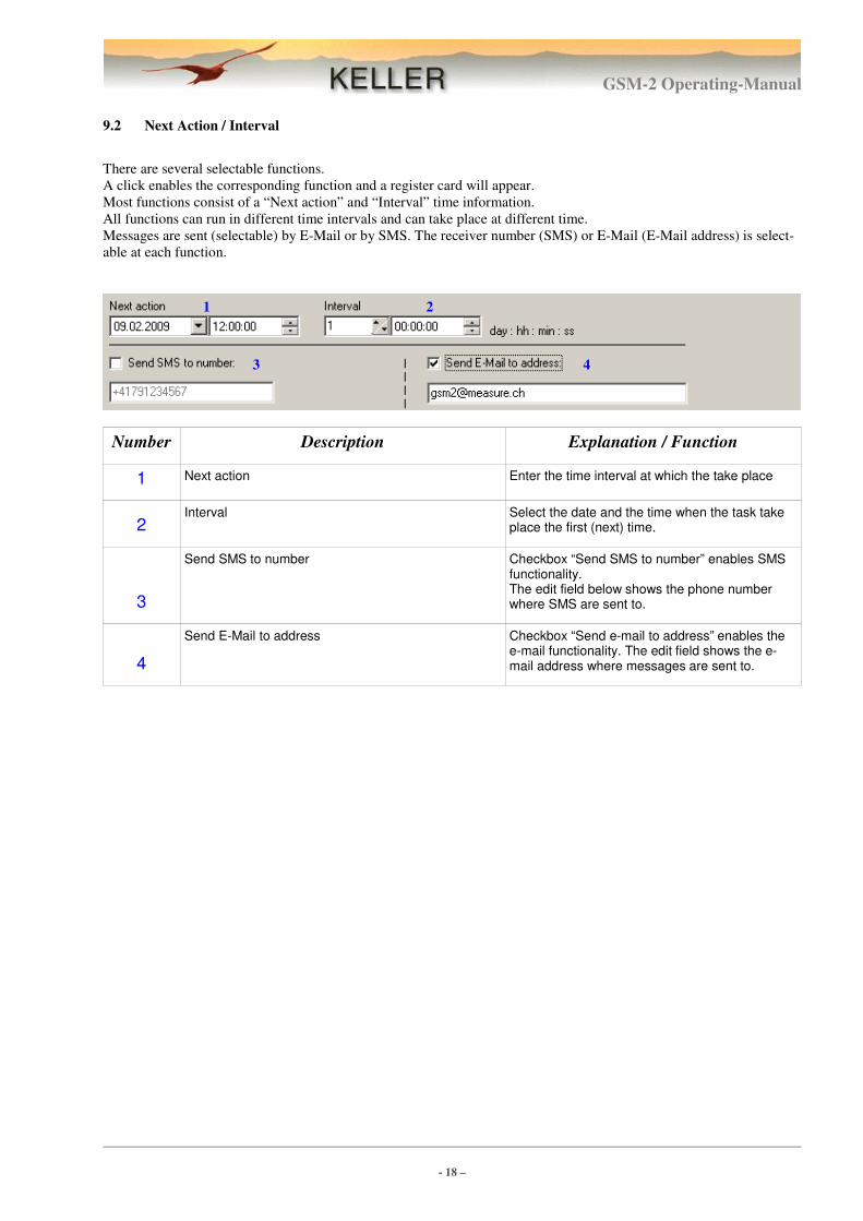
9.2 Next Action / Interval
There are several selectable functions.
A click enables the corresponding function and a register card will appear.
Most functions consist of a “Next action” and “Interval” time information.
All functions can run in different time intervals and can take place at different time.
Messages are sent (selectable) by E-Mail or by SMS. The receiver number (SMS) or E-Mail (E-Mail address) is select-
able at each function.
Number Description Explanation / Function
1 Next action Enter the time interval at which the take place
2 Interval Select the date and the time when the task take
place the first (next) time.
3
Send SMS to number Checkbox “Send SMS to number” enables SMS functionality. The edit field below shows the phone number where SMS are sent to.
4
Send E-Mail to address Checkbox “Send e-mail to address” enables the e-mail functionality. The edit field shows the e-mail address where messages are sent to.
2 1
3 4
GSM-2 Operating-Manual
- 19 –
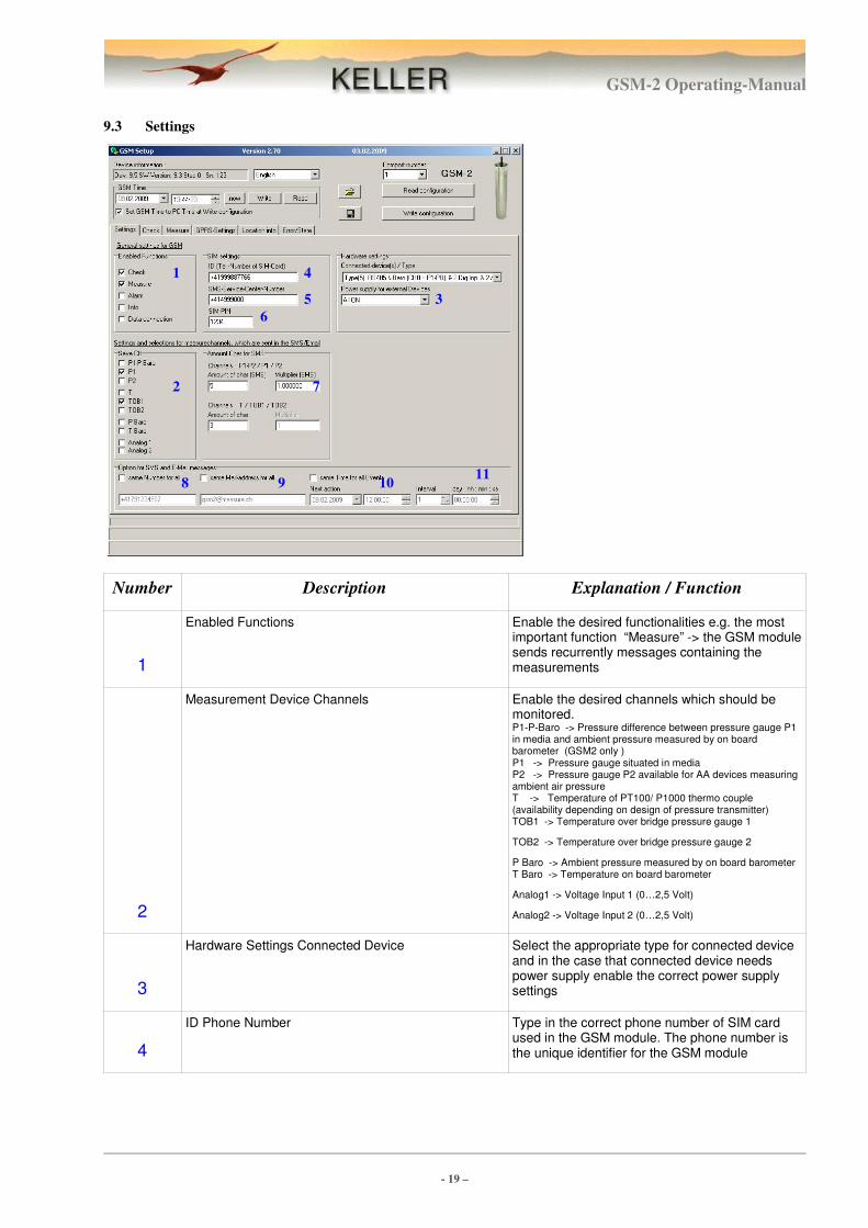
9.3 Settings
Number Description Explanation / Function
1
Enabled Functions Enable the desired functionalities e.g. the most important function “Measure” -> the GSM module sends recurrently messages containing the measurements
2
Measurement Device Channels Enable the desired channels which should be monitored. P1-P-Baro -> Pressure difference between pressure gauge P1 in media and ambient pressure measured by on board barometer (GSM2 only ) P1 -> Pressure gauge situated in media P2 -> Pressure gauge P2 available for AA devices measuring ambient air pressure T -> Temperature of PT100/ P1000 thermo couple (availability depending on design of pressure transmitter) TOB1 -> Temperature over bridge pressure gauge 1
TOB2 -> Temperature over bridge pressure gauge 2
P Baro -> Ambient pressure measured by on board barometer T Baro -> Temperature on board barometer
Analog1 -> Voltage Input 1 (0…2,5 Volt)
Analog2 -> Voltage Input 2 (0…2,5 Volt)
3
Hardware Settings Connected Device Select the appropriate type for connected device and in the case that connected device needs power supply enable the correct power supply settings
4
ID Phone Number Type in the correct phone number of SIM card used in the GSM module. The phone number is the unique identifier for the GSM module
7 2
3
4
5
6
1
8 9 10 11
GSM-2 Operating-Manual
- 20 –
Number Description Explanation / Function
5
SMS Service Center Phone number of the SMS gateway of your service provider.
Enter the telephone number of your telephone company's SMS center here. SMS messages cannot be sent without this number!
6
Pin Code Pin Code of the SIM Card.
If PIN is deactivated, leave this box blank or put any number in it.
7
Amount of Chars used in SMS SMS has a rigid limitation of the total number of characters being transmitted. You may adapt the number of characters used to store one measurement value of temperature and pressure. Please notice that the number of channels and number of measurements sent in one SMS message may require adaptation of the total number of characters used to store a single value with respect of achieving reasonable accuracy and without loosing information.
8
Options for SMS Generally the module allows to send e.g. “Measure” and “Alarm” messages to independent numbers. The checkbox “Same number for all” offers the possibility to synchronize all edit fields for the target phone number. Enabling the checkbox activates the edit field below to work as the central edit field for the target phone number for all message types or “Enabled Functions” respectively.
9 Options for e-mail address Analogous to SMS but for e-mail
10
“same time for all events” When checkbox is enabled then the edit fields for start time/date and send interval are synchronized.
“Next action” specifies when the GSM module should start with operation and sending measuring values.
11 Interval Interval specifies the cadence of sending
recurrently information
GSM-2 Operating-Manual
- 21 –
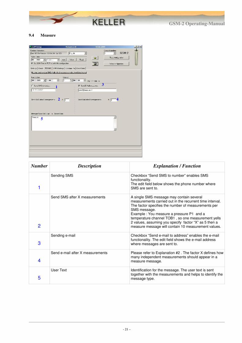
9.4 Measure
Number Description Explanation / Function
1
Sending SMS Checkbox “Send SMS to number” enables SMS functionality. The edit field below shows the phone number where SMS are sent to.
2
Send SMS after X measurements A single SMS message may contain several measurements carried out in the recurrent time interval. The factor specifies the number of measurements per SMS message. Example : You measure a pressure P1 and a temperature channel TOB1 , so one measurement yells 2 values, assuming you specify factor “X” as 5 then a measure message will contain 10 measurement values.
3
Sending e-mail Checkbox “Send e-mail to address” enables the e-mail functionality. The edit field shows the e-mail address where messages are sent to.
4
Send e-mail after X measurements Please refer to Explanation #2 . The factor X defines how many independent measurements should appear in a measure message.
5
User Text Identification for the message. The user text is sent together with the measurements and helps to identify the message type.
2
3
4
5
1
GSM-2 Operating-Manual
- 22 –
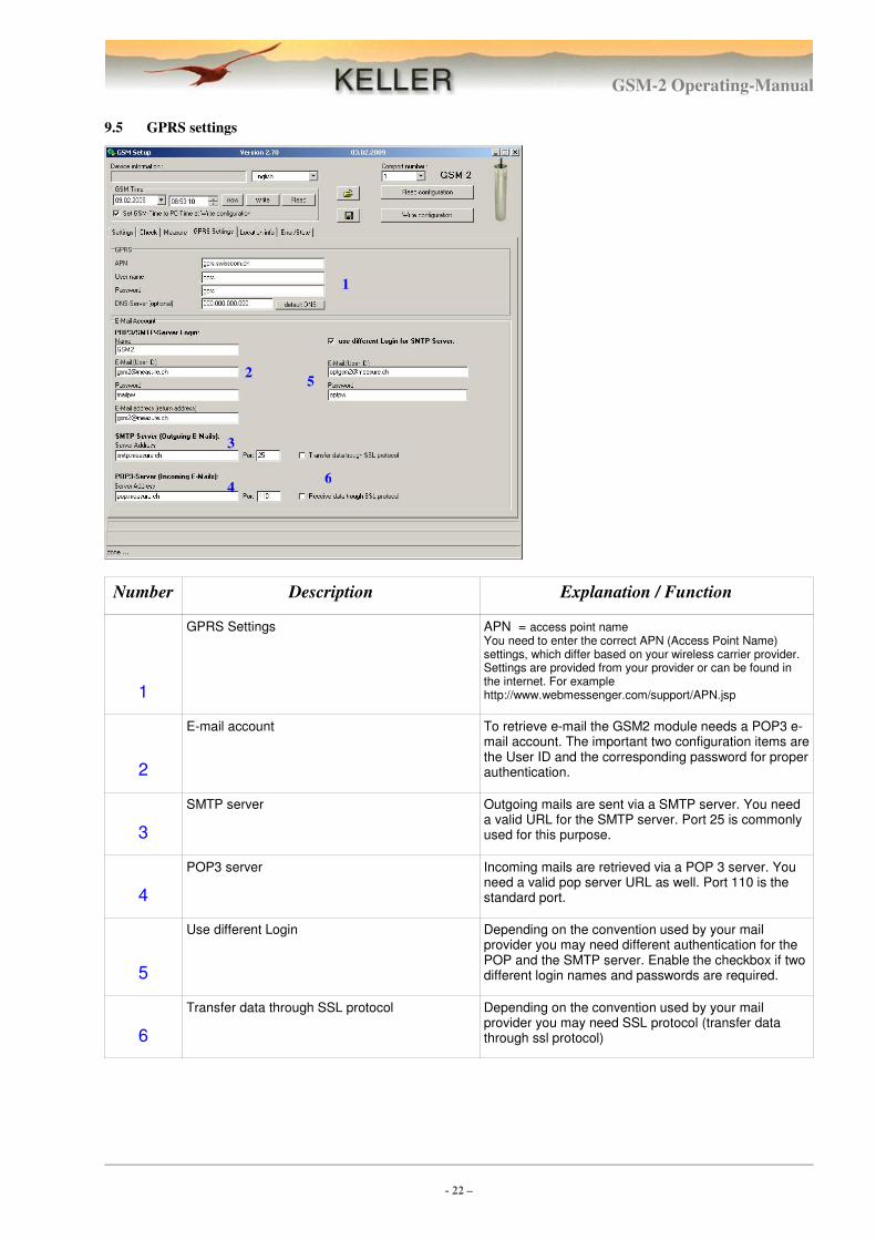
9.5 GPRS settings
Number Description Explanation / Function
1
GPRS Settings APN = access point name You need to enter the correct APN (Access Point Name) settings, which differ based on your wireless carrier provider. Settings are provided from your provider or can be found in the internet. For example http://www.webmessenger.com/support/APN.jsp
2
E-mail account To retrieve e-mail the GSM2 module needs a POP3 e-mail account. The important two configuration items are the User ID and the corresponding password for proper authentication.
3
SMTP server Outgoing mails are sent via a SMTP server. You need a valid URL for the SMTP server. Port 25 is commonly used for this purpose.
4
POP3 server Incoming mails are retrieved via a POP 3 server. You need a valid pop server URL as well. Port 110 is the standard port.
5
Use different Login Depending on the convention used by your mail provider you may need different authentication for the POP and the SMTP server. Enable the checkbox if two different login names and passwords are required.
6
Transfer data through SSL protocol Depending on the convention used by your mail provider you may need SSL protocol (transfer data through ssl protocol)
2
3
4
5
1
6
GSM-2 Operating-Manual
- 23 –
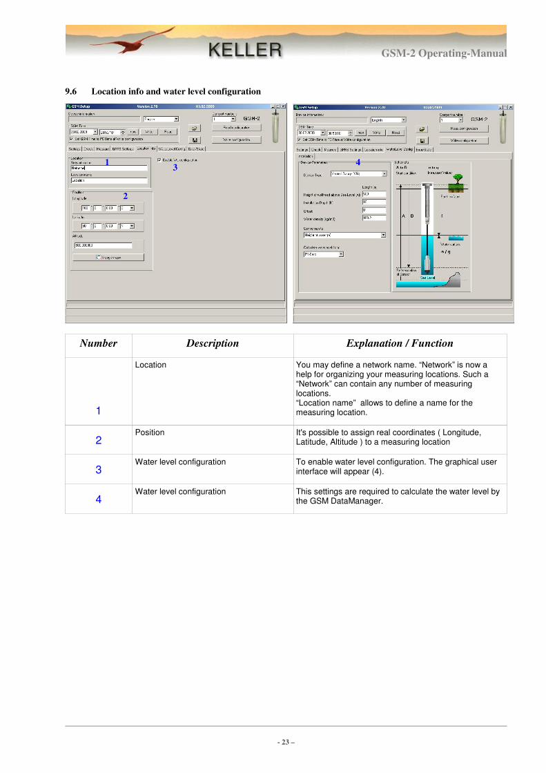
9.6 Location info and water level configuration
Number Description Explanation / Function
1
Location You may define a network name. “Network” is now a help for organizing your measuring locations. Such a “Network” can contain any number of measuring locations. “Location name” allows to define a name for the measuring location.
2 Position It's possible to assign real coordinates ( Longitude,
Latitude, Altitude ) to a measuring location
3 Water level configuration To enable water level configuration. The graphical user
interface will appear (4).
4 Water level configuration This settings are required to calculate the water level by
the GSM DataManager.
2
3 4 1
GSM-2 Operating-Manual
- 24 –
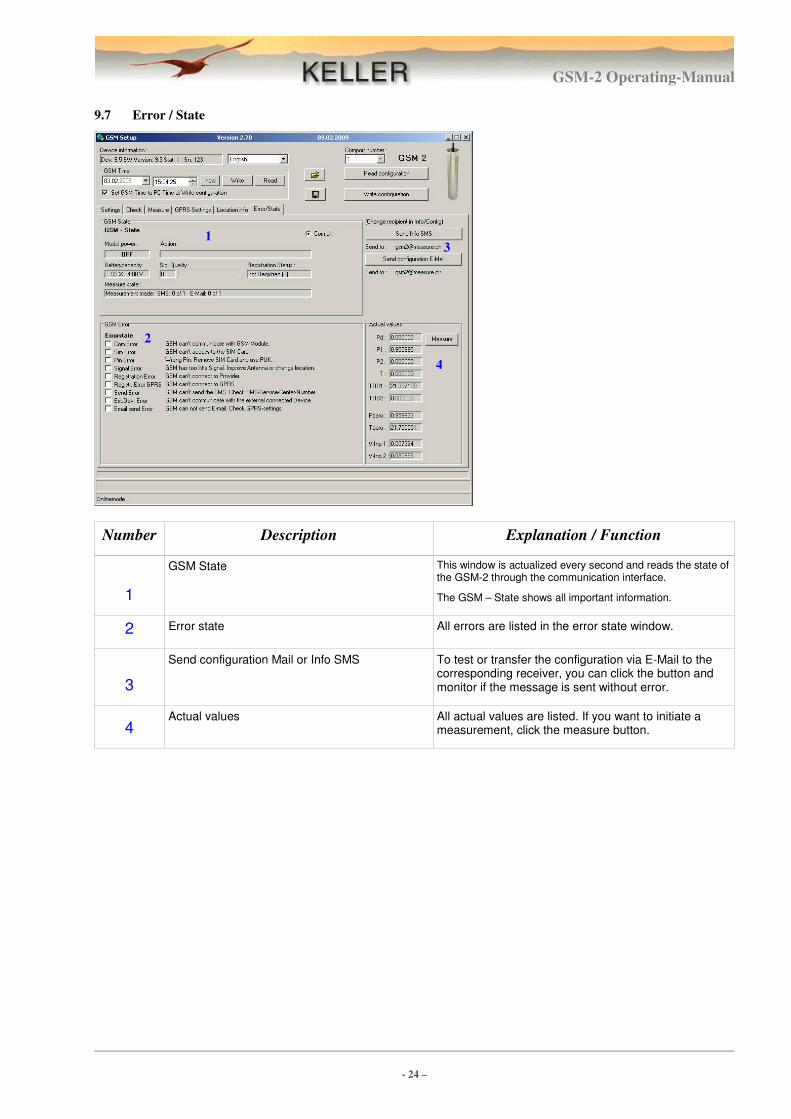
9.7 Error / State
Number Description Explanation / Function
1
GSM State This window is actualized every second and reads the state of the GSM-2 through the communication interface.
The GSM – State shows all important information.
2 Error state All errors are listed in the error state window.
3
Send configuration Mail or Info SMS To test or transfer the configuration via E-Mail to the corresponding receiver, you can click the button and monitor if the message is sent without error.
4 Actual values All actual values are listed. If you want to initiate a
measurement, click the measure button.
2
3
4
1
GSM-2 Operating-Manual
- 25 –
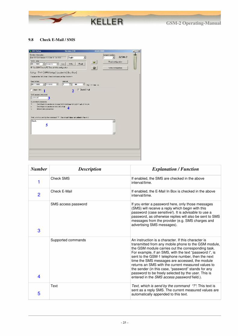
9.8 Check E-Mail / SMS
Number Description Explanation / Function
1 Check SMS If enabled, the SMS are checked in the above
interval/time.
2 Check E-Mail If enabled, the E-Mail In Box is checked in the above
interval/time.
3
SMS access password If you enter a password here, only those messages (SMS) will receive a reply which begin with this password (case sensitive!). It is advisable to use a password, as otherwise replies will also be sent to SMS messages from the provider (e.g. SMS charges and advertising SMS messages).
4
Supported commands An instruction is a character. If this character is transmitted from any mobile phone to the GSM module, the GSM module carries out the corresponding task. For example, if an SMS, with the text “password i”, is sent to the GSM-1 telephone number, then the next time the SMS messages are accessed, the module returns an SMS with the current measured values to the sender (in this case, “password” stands for any password to be freely selected by the user. This is entered in the SMS access password field.).
5
Text Text, which is send by the command “?”: This text is sent as a reply SMS. The current measured values are automatically appended to this text.
2
3
4
1
5
GSM-2 Operating-Manual
- 26 –
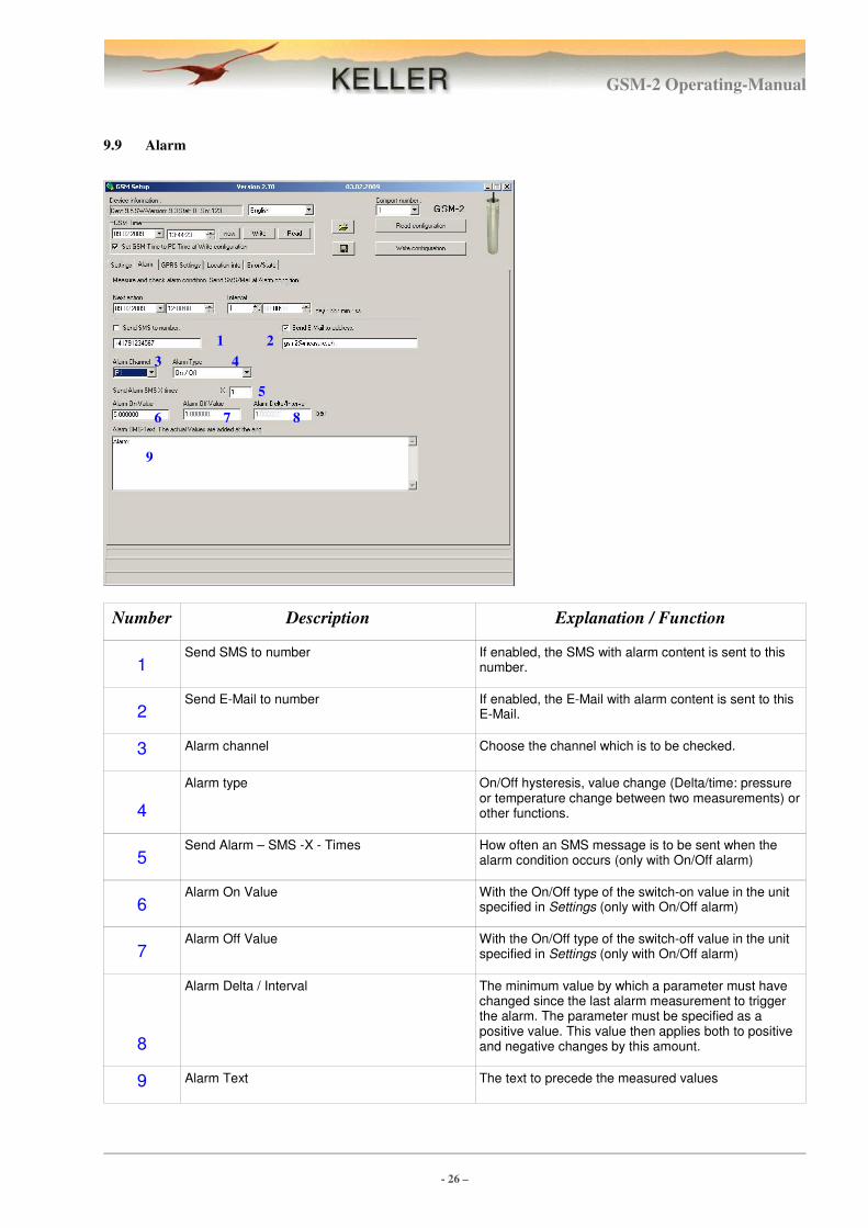
9.9 Alarm
Number Description Explanation / Function
1 Send SMS to number If enabled, the SMS with alarm content is sent to this
number.
2 Send E-Mail to number If enabled, the E-Mail with alarm content is sent to this
E-Mail.
3 Alarm channel Choose the channel which is to be checked.
4
Alarm type On/Off hysteresis, value change (Delta/time: pressure or temperature change between two measurements) or other functions.
5 Send Alarm – SMS -X - Times How often an SMS message is to be sent when the
alarm condition occurs (only with On/Off alarm)
6 Alarm On Value With the On/Off type of the switch-on value in the unit
specified in Settings (only with On/Off alarm)
7 Alarm Off Value With the On/Off type of the switch-off value in the unit
specified in Settings (only with On/Off alarm)
8
Alarm Delta / Interval The minimum value by which a parameter must have changed since the last alarm measurement to trigger the alarm. The parameter must be specified as a positive value. This value then applies both to positive and negative changes by this amount.
9 Alarm Text The text to precede the measured values
2
3 4
1
6
9
5
7 8
GSM-2 Operating-Manual
- 27 –
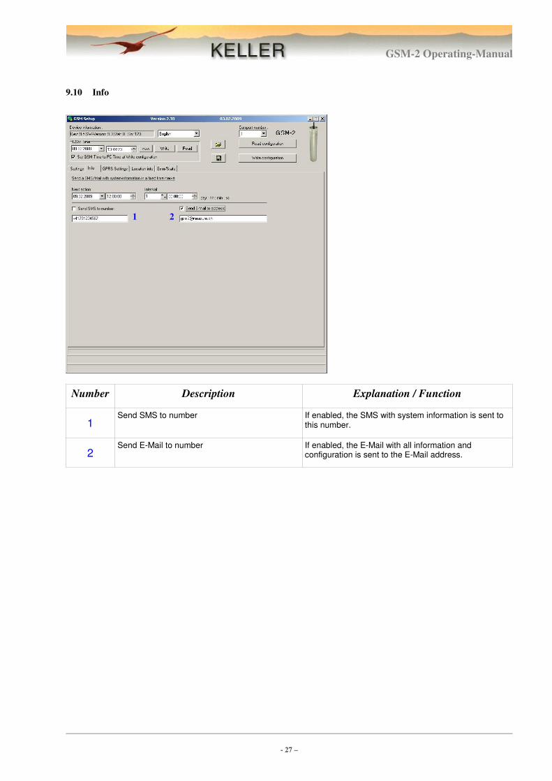
9.10 Info
Number Description Explanation / Function
1 Send SMS to number If enabled, the SMS with system information is sent to
this number.
2 Send E-Mail to number If enabled, the E-Mail with all information and
configuration is sent to the E-Mail address.
2 1
GSM-2 Operating-Manual
- 28 –
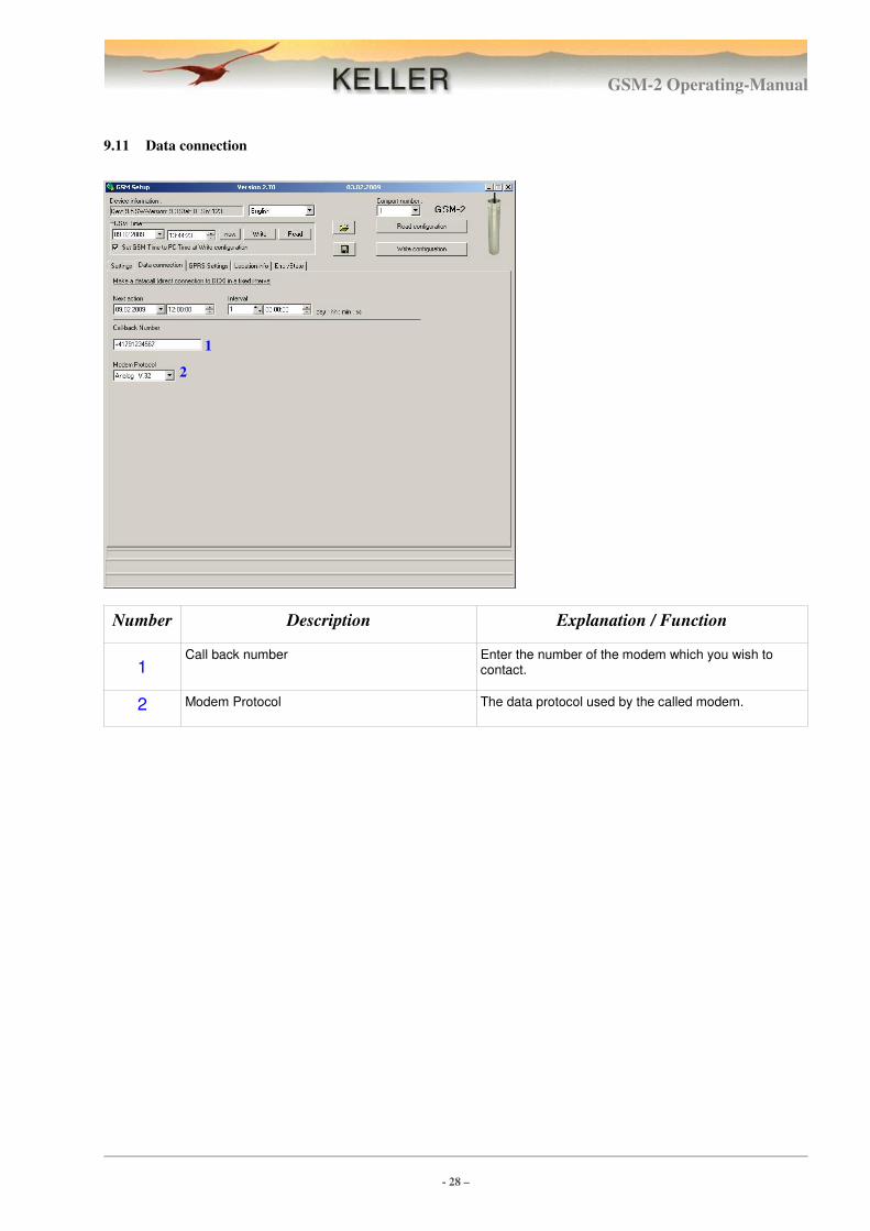
9.11 Data connection
Number Description Explanation / Function
1 Call back number Enter the number of the modem which you wish to
contact.
2 Modem Protocol The data protocol used by the called modem.
2
1
GSM-2 Operating-Manual
- 29 –
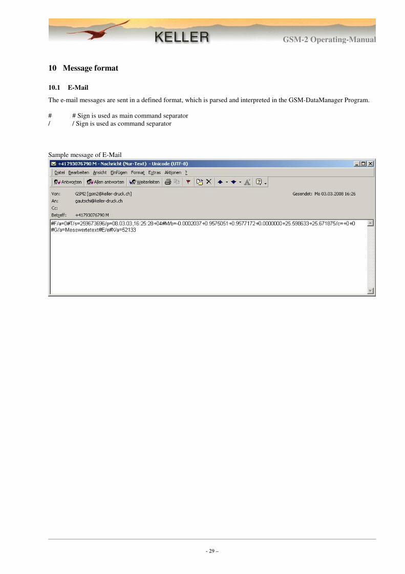
10 Message format
10.1 E-Mail
The e-mail messages are sent in a defined format, which is parsed and interpreted in the GSM-DataManager Program.
# # Sign is used as main command separator
/ / Sign is used as command separator
Sample message of E-Mail
GSM-2 Operating-Manual
- 30 –
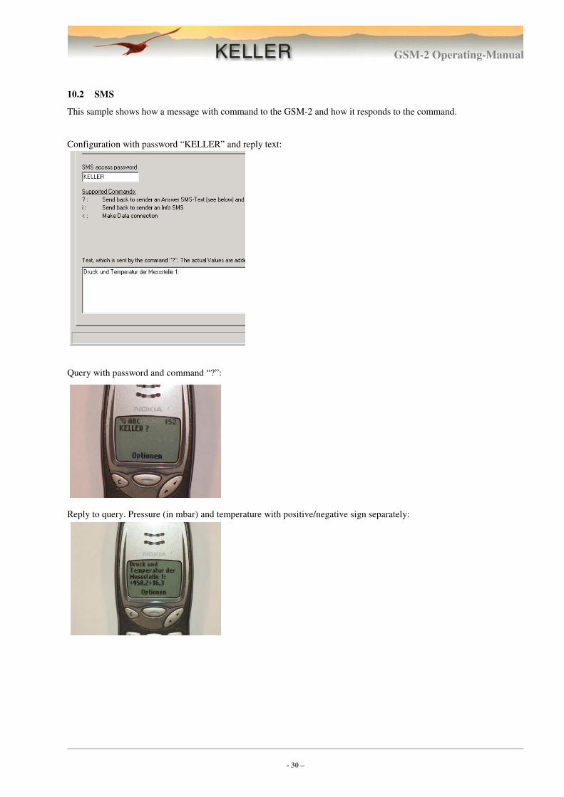
10.2 SMS
This sample shows how a message with command to the GSM-2 and how it responds to the command.
Configuration with password “KELLER” and reply text:
Query with password and command “?”:
Reply to query. Pressure (in mbar) and temperature with positive/negative sign separately:
GSM-2 Operating-Manual
- 31 –
11 Data connection
This function was used in the GSM-1. For compatibility reason it is also supplied in the GSM-2. We do not
recommend to use that function in new projects, use the E-Mail function.
When a data connection is established, the data from the Data collector DCX connected to the GSM can be accessed
world-wide via modem. If a data logger is connected, the entire memory content can be read out. It is also possible to
reconfigure the logger.
A data connection can be made only from the module to the PC. The user is always called from the GSM module. The
call time can be specified in the configuration. An additional, more flexible possibility is to send an SMS to the module,
which requests a data connection (with the instruction “<”). The next time the module checks incoming SMS messages,
it recognises that a data connection has been requested. It immediately dials the relevant number and establishes the
data connection with the user’s modem.
Preparation for connecting the call
The call can be made either with an analogue or a digital (ISDN) modem. The use of an external modem is recom-
mended.
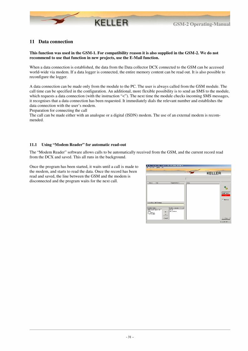
11.1 Using “Modem Reader” for automatic read-out
The “Modem Reader” software allows calls to be automatically received from the GSM, and the current record read
from the DCX and saved. This all runs in the background.
Once the program has been started, it waits until a call is made to
the modem, and starts to read the data. Once the record has been
read and saved, the line between the GSM and the modem is
disconnected and the program waits for the next call.
GSM-2 Operating-Manual
- 32 –
12 E-Mail configuration
We recommend to use (at least) 2 E-Mail accounts in conjunction with the GSM DataManager.
1 E-Mail Box where the GSM-2 Modules send the measurement and the configuration and 1 E-Mail Box for configura-
tions sent from GSM DataManager to the GSM-2 Modules.
This helps to save battery and money, because the modules download only Mails from the E-Mail Box with configura-
tion (if new configuration sent from the GSM DataManager) and not also messages with measurement content from all
the modules communicating to this Mail address.
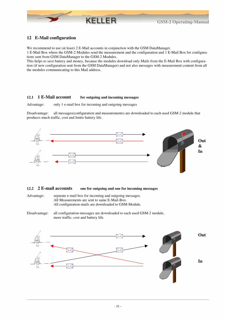
12.1 1 E-Mail account for outgoing and incoming messages
Advantage: only 1 e-mail box for incoming and outgoing messages
Disadvantage: all messages(configuration and measurements) are downloaded to each used GSM-2 module that
produces much traffic, cost and limits battery life.
12.2 2 E-mail accounts one for outgoing and one for incoming messages
Advantage: separate e-mail box for incoming and outgoing messages.
All Measurements are sent to same E-Mail-Box.
All configuration-mails are downloaded to GSM-Module.
Disadvantage: all configuration-messages are downloaded to each used GSM-2 module,
more traffic, cost and battery life.
Out
&
In
Out
In
GSM-2 Operating-Manual
- 33 –
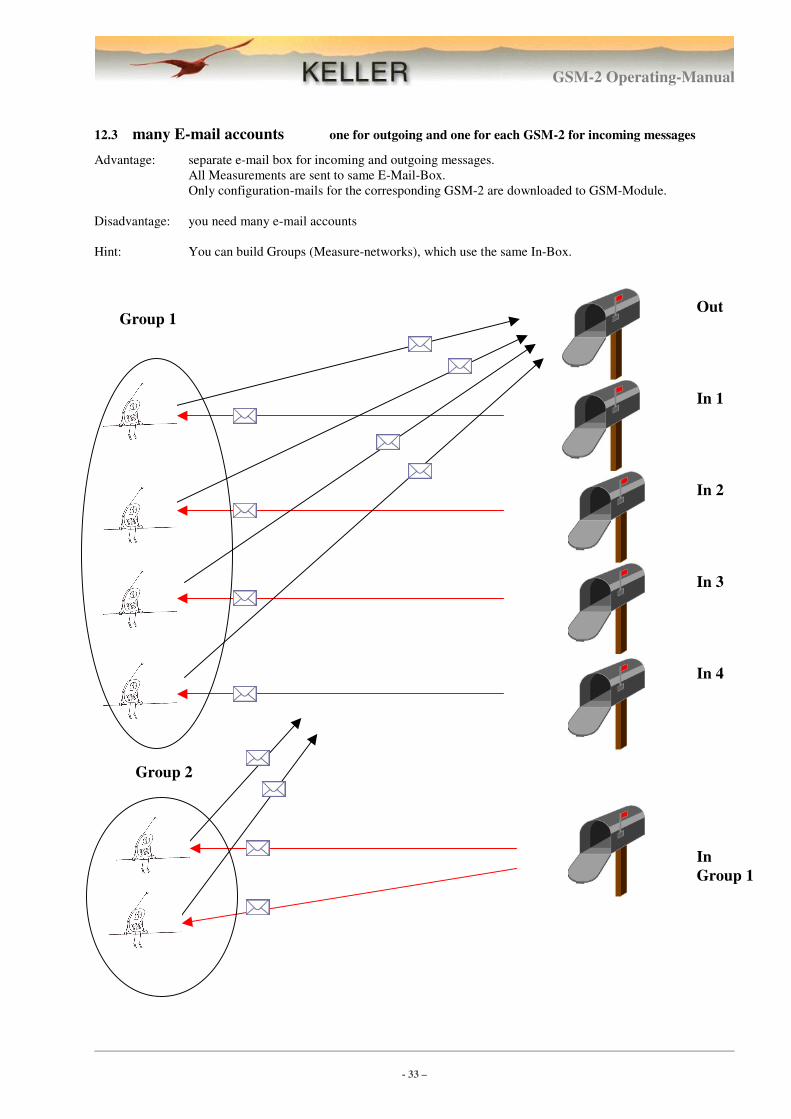
12.3 many E-mail accounts one for outgoing and one for each GSM-2 for incoming messages
Advantage: separate e-mail box for incoming and outgoing messages.
All Measurements are sent to same E-Mail-Box.
Only configuration-mails for the corresponding GSM-2 are downloaded to GSM-Module.
Disadvantage: you need many e-mail accounts
Hint: You can build Groups (Measure-networks), which use the same In-Box.
Out
In 1
In 2
In 3
In 4
In
Group 1
Group 2
Group 1
GSM-2 Operating-Manual
- 34 –
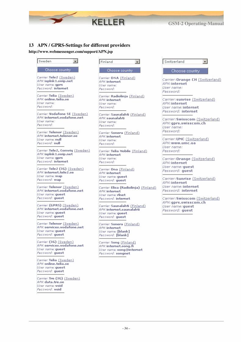
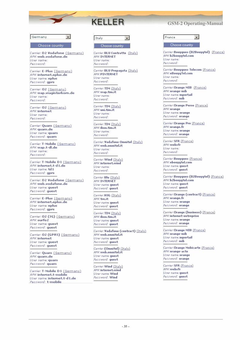
13 APN / GPRS-Settings for different providers
http://www.webmessenger.com/support/APN.jsp
GSM-2 Operating-Manual
- 35 –
GSM-2 Operating-Manual
- 36 –
14 First installation step by step
The configuration below shows how a installation and configuration can take place. It is a standard configuration
suitable for most applications.
Sample shows following configuration:
� GSM-2 with level senor (Series 36 XW) connected. Connection RS485 and 12 Volt supply.
� 2 E-Mail accounts. [email protected] to send Messages with measurements to DataManager,
[email protected] to send new configuration from DataManager to GSM-2.
� Measure interval is 1 hour, sending E-Mail with 24 measure values every day (24 hour)
� check interval for incoming E-Mail (configuration from DataManager to GSM-2) every day (24 hour), same
time like sending measurements to DataManager.
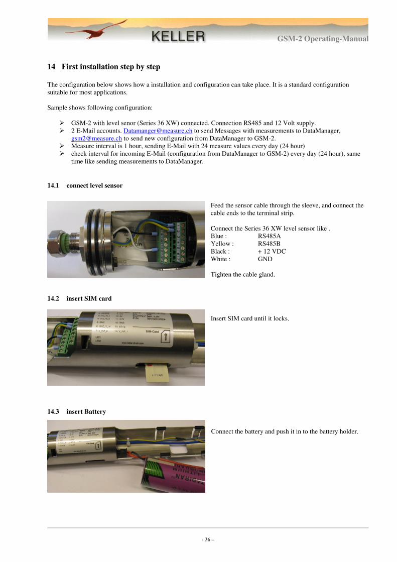
14.1 connect level sensor
Feed the sensor cable through the sleeve, and connect the
cable ends to the terminal strip.
Connect the Series 36 XW level sensor like .
Blue : RS485A
Yellow : RS485B
Black : + 12 VDC
White : GND
Tighten the cable gland.
14.2 insert SIM card
Insert SIM card until it locks.
14.3 insert Battery
Connect the battery and push it in to the battery holder.
GSM-2 Operating-Manual
- 37 –
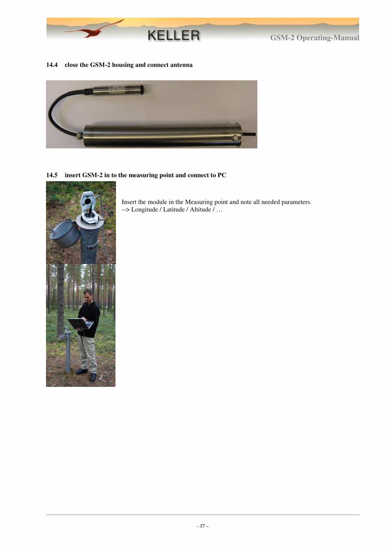
14.4 close the GSM-2 housing and connect antenna
14.5 insert GSM-2 in to the measuring point and connect to PC
Insert the module in the Measuring point and note all needed parameters.
--> Longitude / Latitude / Altitude / …
GSM-2 Operating-Manual
- 38 –
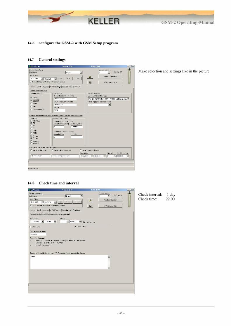
14.6 configure the GSM-2 with GSM Setup program
14.7 General settings
Make selection and settings like in the picture.
14.8 Check time and interval
Check interval: 1 day
Check time: 22.00
GSM-2 Operating-Manual
- 39 –
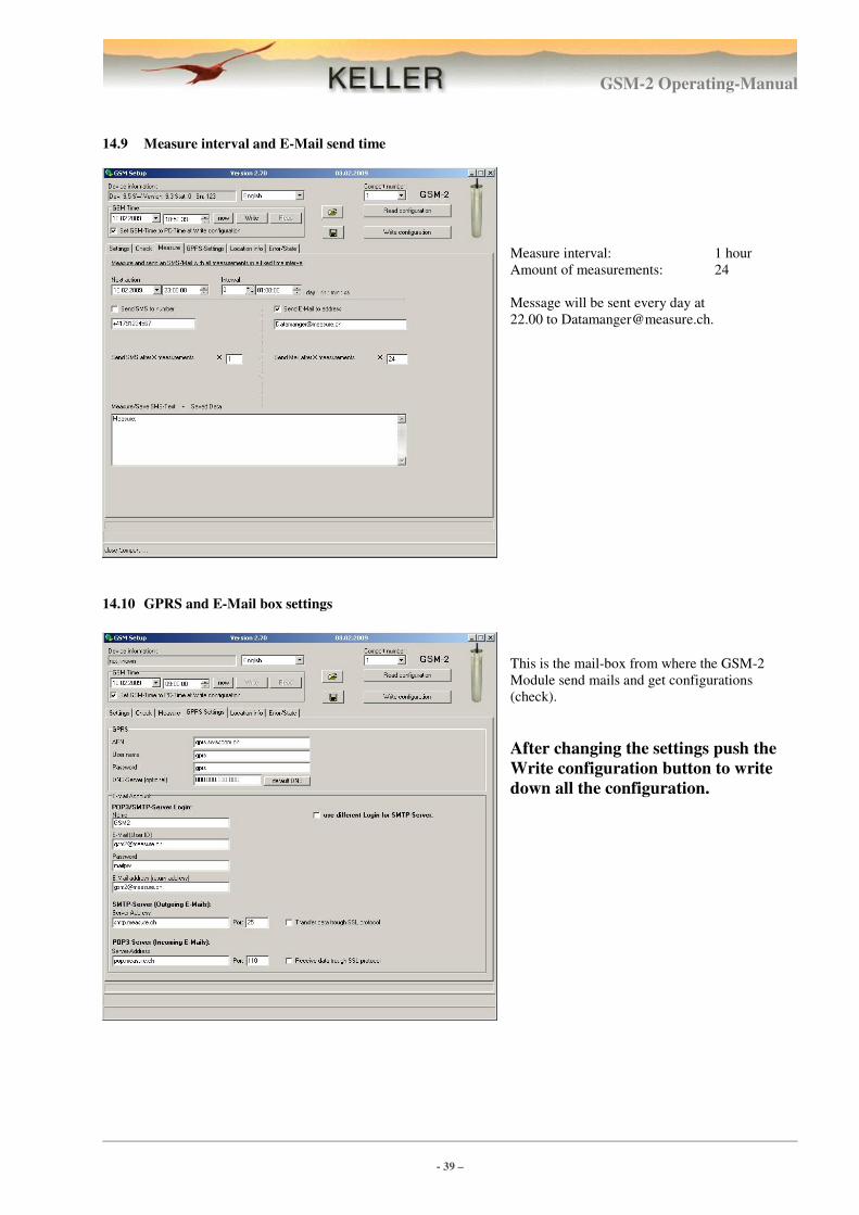
14.9 Measure interval and E-Mail send time
Measure interval: 1 hour
Amount of measurements: 24
Message will be sent every day at
22.00 to [email protected].
14.10 GPRS and E-Mail box settings
This is the mail-box from where the GSM-2
Module send mails and get configurations
(check).
After changing the settings push the
Write configuration button to write
down all the configuration.
GSM-2 Operating-Manual
- 40 –
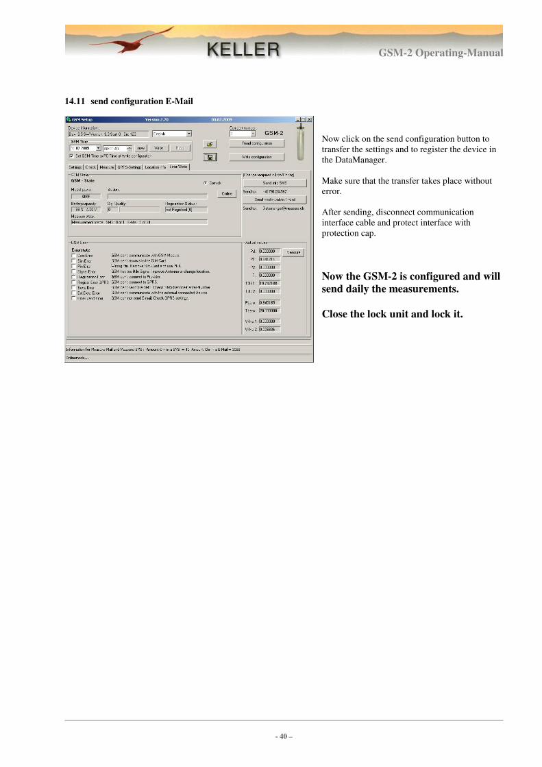
14.11 send configuration E-Mail
Now click on the send configuration button to
transfer the settings and to register the device in
the DataManager.
Make sure that the transfer takes place without
error.
After sending, disconnect communication
interface cable and protect interface with
protection cap.
Now the GSM-2 is configured and will
send daily the measurements.
Close the lock unit and lock it.