Embed Size (px)
Citation preview

Rev.140310001
Operating Manual
BCP-O2
BCP X-large
Aluminum IP65
BCP regular
with PA 6 housing
BCP-O2 OPERATING MANUAL
Rev. 140310001 1
Contents
1 ABOUT THIS DOCUMENT ................................................................................................................ 2
1.1 Function ......................................................................................................................................................... 2
1.2 Target group .................................................................................................................................................. 2
1.3 Symbols used ................................................................................................................................................ 2
2 FOR YOUR SAFETY .......................................................................................................................... 3
2.1 General information ....................................................................................................................................... 3
2.2 Authorized personnel .................................................................................................................................... 3
2.3 Proper use ..................................................................................................................................................... 3
2.4 Misuse warning ............................................................................................................................................. 3
2.5 General safety information ............................................................................................................................ 3
2.6 CE conformity ................................................................................................................................................ 4
3 PRODUCT DESCRIPTION ................................................................................................................ 4
3.1 One-piece construction of the BCP-O2 ......................................................................................................... 4
3.2 Measuring principle ....................................................................................................................................... 6
4 INSTALLATION .................................................................................................................................. 6
4.1 General instructions ...................................................................................................................................... 6
4.2 Mechanical connection .................................................................................................................................. 8
4.2.1 Installation on pipes ................................................................................................................................. 9
4.2.2 Installation on a Tri-Clamp SMS38 connection ........................................................................................ 9
4.2.3 Installation on a POM flow adapter ........................................................................................................ 10
4.2.4 Installation on a stainless steel flow adapter .......................................................................................... 10
4.2.5 Sterile installation at the shake flask ...................................................................................................... 11
4.3 Electrical connection ................................................................................................................................... 17
4.3.1 General information ................................................................................................................................ 17
4.3.2 Version 4 – 20 mA in PA6 housing ........................................................................................................ 18
4.3.3 RS232 serial version in PA6 housing ..................................................................................................... 19
4.3.4 Version 4 – 20 mA in aluminum housing ............................................................................................... 20
4.3.5 RS232 serial version in aluminum housing ............................................................................................ 21
4.3.6 Connection via BACCom12 ................................................................................................................... 22
4.4 Minimization of dilution effects through humidity ........................................................................................ 23
5 MAINTENANCE ............................................................................................................................... 24
5.1 1-point calibration ........................................................................................................................................ 24
5.2 Recalibration ............................................................................................................................................... 24
5.3 Filter change – coarse filter ......................................................................................................................... 25
5.3.1 Removing the filter cover ....................................................................................................................... 25
5.3.2 Changing the filter .................................................................................................................................. 25
5.4 Filter change PES cap................................................................................................................................. 25
6 APPENDIX ....................................................................................................................................... 26
6.1 Calibration table .......................................................................................................................................... 26
6.2 Technical data ............................................................................................................................................. 27

BCP-O2 OPERATING MANUAL
Rev. 140310001 2
1 About this document
1.1 Function
This operating manual provides you with all of the necessary information for quick start-up and safe
operation of the BCP-O2. Please read the operating manual before starting operation.
1.2 Target group
This operating manual is intended for use by trained specialist personnel. The contents of this manual
must be made available to personnel and followed by them.
1.3 Symbols used
Danger!
This symbol indicates a situation that is possibly dangerous. Failure to observe the safety
instructions can result in personal injury.
Caution!
The symbol indicates the possibility of damage to property.
Note!
This symbol indicates helpful additional information.
1 Action sequence
Numbers indicate steps to be performed in sequence.

BCP-O2 OPERATING MANUAL
Rev. 140310001 3
2 For your safety
2.1 General information
The BCP-O2 was inspected in our plant and was ready for operation when it left.
Before installing and starting up the device, please read this operating manual carefully. The operating
manual contains safety instructions that must be observed to ensure safe operation.
The device must never be operated in conditions that do not comply with the specifications on the type
plate.
Maintenance and servicing may only be performed by specially trained personnel who are familiar with
the hazards inherent to the work as well as the guarantee terms.
2.2 Authorized personnel
All of the actions described in this operating manual may only be performed by trained specialist
personnel who have been authorized by the plant operator. Work on the device other than that described
in this manual may only be performed by personnel of the BlueSens gas sensor GmbH Company for
safety reasons and to ensure compliance with the terms of the guarantee.
2.3 Proper use
The BCP-O2 is a gas sensor for measuring oxygen concentrations in the specified concentration area
and under the conditions described in the technical data. It is used to monitor metabolism in biological
processes such as fermentation. The BCP-O2 sensor may only be used in well ventilated rooms.
Danger!
The sensor does not have an ATEX certificate and may therefore only be used in well ventilated
rooms.
2.4 Misuse warning
The BCP-O2 may not be used as a safety component for monitoring gasses in systems or as a gas
warning device. It may also not be used in areas subject to explosion hazards.
2.5 General safety information
If the device is mishandled or not used for its intended purpose, application-specific dangers may arise.
Danger!
If the device is incorrectly installed or set, there is a danger of explosions and poisoning.
After installation, check all connections for leaks.
BCP-O2 OPERATING MANUAL
Rev. 140310001 4
2.6 CE conformity
The BCP-O2 conforms to the EMC Directive (89/336/EEC, 92/31/EEC and 93/68/EEC) when applying
the harmonized standards EN50081–1, EN61000.
The low-voltage directive (72/23/EEC und 93/68/EEC) is not applicable as no voltage greater than 24 V
is used.
3 Product description
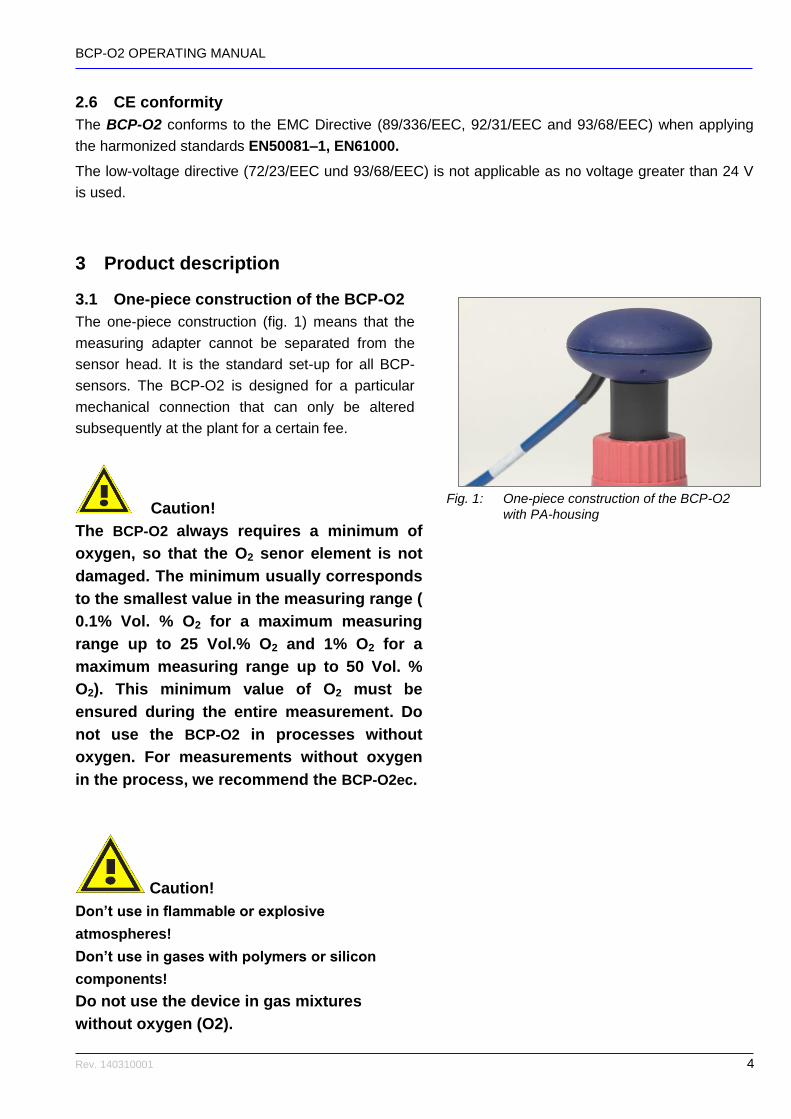
3.1 One-piece construction of the BCP-O2
The one-piece construction (fig. 1) means that the
measuring adapter cannot be separated from the
sensor head. It is the standard set-up for all BCP-
sensors. The BCP-O2 is designed for a particular
mechanical connection that can only be altered
subsequently at the plant for a certain fee.
Caution!
The BCP-O2 always requires a minimum of
oxygen, so that the O2 senor element is not
damaged. The minimum usually corresponds
to the smallest value in the measuring range (
0.1% Vol. % O2 for a maximum measuring
range up to 25 Vol.% O2 and 1% O2 for a
maximum measuring range up to 50 Vol. %
O2). This minimum value of O2 must be
ensured during the entire measurement. Do
not use the BCP-O2 in processes without
oxygen. For measurements without oxygen
in the process, we recommend the BCP-O2ec.
Caution!
Don’t use in flammable or explosive
atmospheres!
Don’t use in gases with polymers or silicon
components!
Do not use the device in gas mixtures
without oxygen (O2).
Fig. 1: One-piece construction of the BCP-O2
with PA-housing

BCP-O2 OPERATING MANUAL
Rev. 140310001 5
Don’t use in gases with halogens like F, Cl, Br
etc., CFC or SOx and H2S!
Sensor could be destroyed if it is put in use
with 100% relative humidity inside. Make sure
every time that the sensor is warmer than its
environment or that max. 75% humidity is
inside the sensor.
Don’t expose sensor to water or humidity over
75% RH when the sensor is not in use. Sensor
could be damaged.
Otherwise it could be dried at max. 80°C
(176°F) for 3 hours on a hot plate or a drying
chamber.
Measuring adapter will become hot. Don’t touch
in use under power. Disconnect the power
supply and wait 30 minutes for cooling.
A Teflon filter is placed at the bottom of the cap to
protect the sensor element for a short time against
water under normal pressure. In the case of over
pressure this could not be guaranteed.
If foam or dust pollutes the Teflon filter it has to be
changed (see chapter 5.3 Filter change – coarse
filter). Behind the Teflon filter there is a second
filter. If this filter is polluted, don’t change it! Call the
service of BlueSens.
If the senor element gets in contact with water
it could be destroyed. In this case the sensor
needs a new element and a new factory
calibration at the BlueSens site.
Caution!
The filter does not serve to protect the sensor against
water under overpressure.
If the measuring cap is full of water the sensor
element has to be dried at max. 80°C.
Don’t change the second filter of the sensor! Sensor
could be destroyed.
Fig. 2: Teflon filter
BCP-O2 OPERATING MANUAL
Rev. 140310001 6
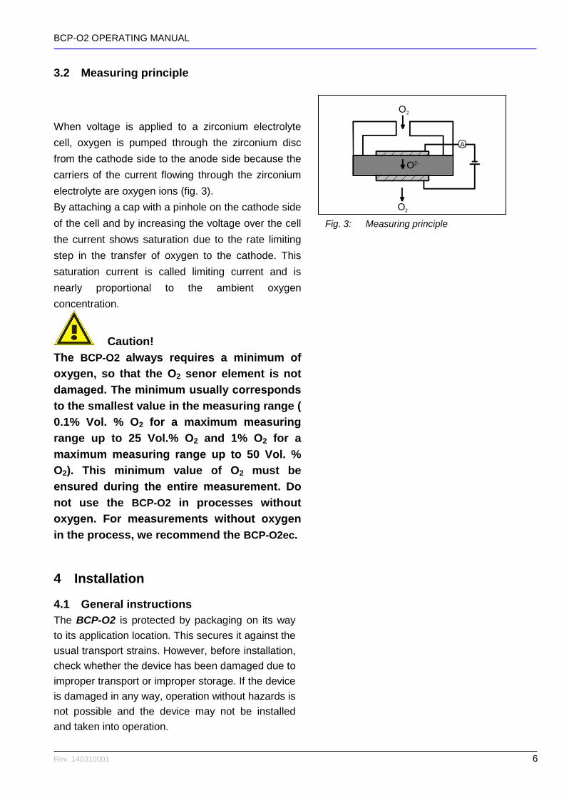
3.2 Measuring principle
When voltage is applied to a zirconium electrolyte
cell, oxygen is pumped through the zirconium disc
from the cathode side to the anode side because the
carriers of the current flowing through the zirconium
electrolyte are oxygen ions (fig. 3).
By attaching a cap with a pinhole on the cathode side
of the cell and by increasing the voltage over the cell
the current shows saturation due to the rate limiting
step in the transfer of oxygen to the cathode. This
saturation current is called limiting current and is
nearly proportional to the ambient oxygen
concentration.
Caution!
The BCP-O2 always requires a minimum of
oxygen, so that the O2 senor element is not
damaged. The minimum usually corresponds
to the smallest value in the measuring range (
0.1% Vol. % O2 for a maximum measuring
range up to 25 Vol.% O2 and 1% O2 for a
maximum measuring range up to 50 Vol. %
O2). This minimum value of O2 must be
ensured during the entire measurement. Do
not use the BCP-O2 in processes without
oxygen. For measurements without oxygen
in the process, we recommend the BCP-O2ec.
4 Installation
4.1 General instructions
The BCP-O2 is protected by packaging on its way
to its application location. This secures it against the
usual transport strains. However, before installation,
check whether the device has been damaged due to
improper transport or improper storage. If the device
is damaged in any way, operation without hazards is
not possible and the device may not be installed
and taken into operation.
Fig. 3: Measuring principle
A
O2
O2-
O2

BCP-O2 OPERATING MANUAL
Rev. 140310001 7
Check whether the enclosed materials such as
seals and screw-caps are suitable for your process
conditions (pressure, temperature, etc.).
The installation should only be performed under
supervision by a specialist and in compliance with
all applicable work safety rules.
Your instrument was protected by packing
during transport to assure normal loads during
transport.
The packing of standard instruments consists of
environment-friendly, recyclable cardboard. For
special versions PE foam or PE foil is also
used. Dispose of the packaging material via
specialised recycling companies.
To avoid high levels of humidity (max. 75%)
and condensing humidity silica gel is added to
the packing.
Storage conditions see data sheet.
Caution!
Sensor could be destroyed if it is put in use with
100% relative humidity inside. Make every time
sure that it is warmer than its environment or that
max. 75% humidity is inside the sensor.
Otherwise it could be dried at max. 80°C (176°F)
on a hot plate or a drying chamber.

BCP-O2 OPERATING MANUAL
Rev. 140310001 8
4.2 Mechanical connection
Caution!
The sterile filter is not intended for repelling
fluids. Never install the sensor such that fluid
can run into the measuring adapter.
If water has penetrated the measuring adapter,
allow it to dry out for at least 12 hours at max.
80°C in a drying cabinet or on a hot plate.
Protect the measuring adapter from penetration
by liquids.
After installation, check that the pipe connection
is gas-tight.

BCP-O2 OPERATING MANUAL
Rev. 140310001 9
4.2.1 Installation on pipes
The connection to a pipe is made with a 1 ¼" nozzle
with an external thread:
1. Place the sealing ring (O-ring 30 x 4 mm, viton,
item no. Z-OR-00003) on the nozzle (fig. 4).
2. Place on the sensor (fig. 5).
3. Connect the nozzle and the sensor with the
screw cap so that the connection is gas-tight (fig.
6).
Note!
Only use the supplied screw caps. Do not use
metal screw caps as they result in thermal
contact between the measuring adapter and the
pipe and thus violate the technical
specifications.
4.2.2 Installation on a Tri-Clamp SMS38
connection
:
1. Place the sealing ring (item no. Z-OR-00013) on
the nozzle (fig. 7).
2. Place on the sensor (fig. 8).
3. Fix the sensor with the Tri-Clamp on the nozzle
(fig. 9).
Fig. 4 Fig. 5
Fig. 6
Fig. 7 Fig. 8
Fig. 9
BCP-O2 OPERATING MANUAL
Rev. 140310001 10
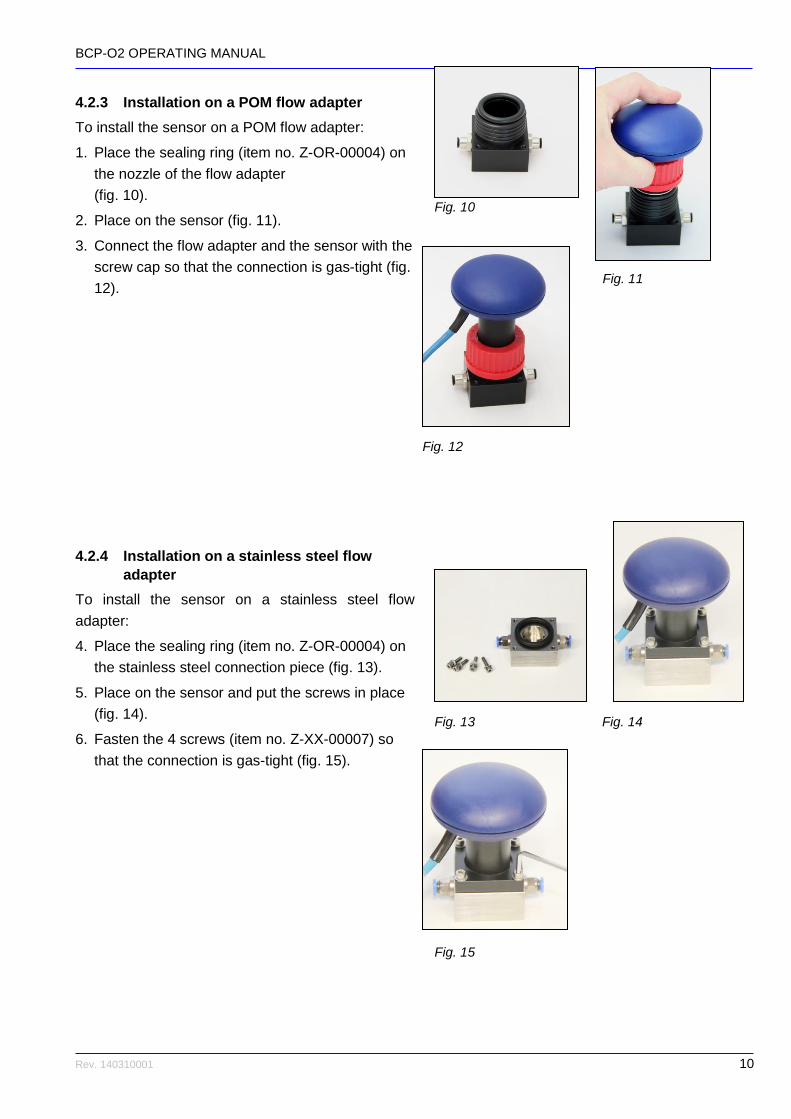
4.2.3 Installation on a POM flow adapter
To install the sensor on a POM flow adapter:
1. Place the sealing ring (item no. Z-OR-00004) on
the nozzle of the flow adapter
(fig. 10).
2. Place on the sensor (fig. 11).
3. Connect the flow adapter and the sensor with the
screw cap so that the connection is gas-tight (fig.
12).
4.2.4 Installation on a stainless steel flow
adapter
To install the sensor on a stainless steel flow
adapter:
4. Place the sealing ring (item no. Z-OR-00004) on
the stainless steel connection piece (fig. 13).
5. Place on the sensor and put the screws in place
(fig. 14).
6. Fasten the 4 screws (item no. Z-XX-00007) so
that the connection is gas-tight (fig. 15).
Fig. 10
Fig. 12
Fig. 13 Fig. 14
Fig. 15
Fig. 11

BCP-O2 OPERATING MANUAL
Rev. 140310001 11
4.2.5 Sterile installation at the shake flask
For sterile conditions with a shake flask
autoclavable PES screwed connections with
integrated filters are available. Before the
measurement the shake flask must be
prepared for the autoclaving (chap. 4.2.6.1
and 4.2.6.2). After the autoclaving the
sensors can be installed (chap. 4.2.6.3).
4.2.5.1 Prepare the shake flask
In the first step the shake flask will be
prepared with screw caps and accessories.
For this installation you will need (fig. 16):
A: shake flask with GL 45 connections. Use
specified shake flasks to ensure a
reproducible calculation of the oxygen and
carbon dioxide transfer rates.
B: A GL14 screw cap (art no. Z-MA-00001)
and a correspondent silicone sealing (art. no.:
Z-OR-00005).
C: (optional for open systems): A PTFE- filter
(art. no.: Z-FL-00001) and a GL45 screw cap
with bore (art. no.: Z-MA-00003) to cover the
unused GL45 nozzles for air ventilation.
D: (optional for gas tight systems): A gasket
GL45 (art. no.: Z-OR-00004) and a screw cap
GL45 (art. no.: Z-MA-00030) to tighten
unused GL45 nozzles.
To prepare the shake flask please proceed
with the following steps:
1. Place the GL14 sealing (art. no.: Z-
OR-00005) on the GL14 nuzzle and
screw the GL 14 cap (art no. Z-MA-
00001) on the nozzle (fig. 17).
Fig. 16
Fig. 17
BCP-O2 OPERATING MANUAL
Rev. 140310001 12
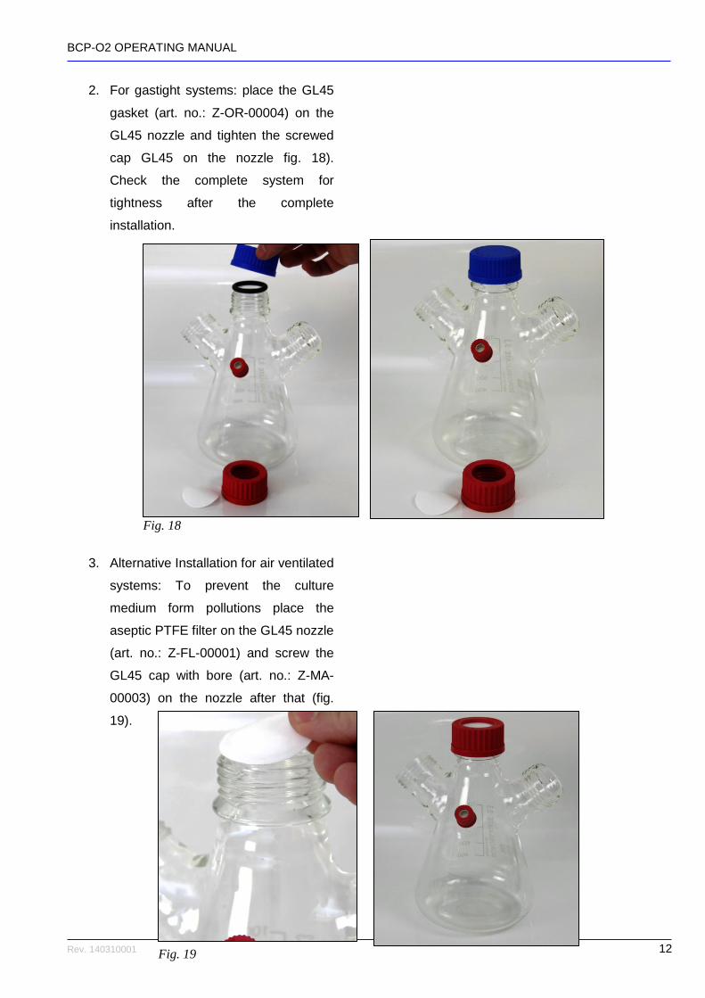
2. For gastight systems: place the GL45
gasket (art. no.: Z-OR-00004) on the
GL45 nozzle and tighten the screwed
cap GL45 on the nozzle fig. 18).
Check the complete system for
tightness after the complete
installation.
3. Alternative Installation for air ventilated
systems: To prevent the culture
medium form pollutions place the
aseptic PTFE filter on the GL45 nozzle
(art. no.: Z-FL-00001) and screw the
GL45 cap with bore (art. no.: Z-MA-
00003) on the nozzle after that (fig.
19).
Fig. 18
Fig. 19

BCP-O2 OPERATING MANUAL
Rev. 140310001 13
4.2.5.2 Preparing the shake flask for autoclaving
Before starting a new measurement the
shake flask with the aseptic filters, the
screwed cap PES GL45 (see accessories, fig.
16: A) and the culture medium has to be
sterilized. To prepare the shake flask for the
autoclaving you will need (fig. 20).
A: The screw cap GL45 PES (art. no.: Z-MA-
00009). This cap was pre-assembled in the
factory and is already equipped with a filter.
See chap.5.4 for information according the
changing of the filter. The PES-cap can be
autoclaved.
B: Two gaskets (art. no.: Z-OR-00004) for
each sensor you want to install.
C: A sensor (at least) with screwed connector
for PES-caps. Please note that the connector
cannot be changed manually. It must be
changed in the BlueSens´ site if you want
another screwed connector type.
D: The already pre-assembled shake flask
(see chap. 4.2.6.1).
Before the autoclaving please proceed in the
following steps:
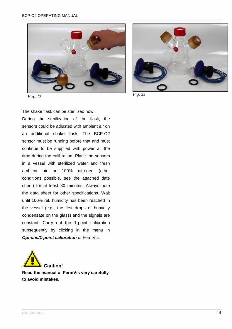
1. Fill in the culture medium (not shown
on images).
2. Place the gasket (art. no.: Z-OR-
00004) on the GL 45 nozzle (fig. 21)
Screw the screwed cap GL45 PES
(art. no.: Z-MA-00009) on the nozzle
(fig. 22). Continue accordingly if you
want to install more than one sensor
(fig. 23).
Fig. 20
Fig. 21
BCP-O2 OPERATING MANUAL
Rev. 140310001 14
The shake flask can be sterilized now.
During the sterilization of the flask, the
sensors could be adjusted with ambient air on
an additional shake flask. The BCP-O2
sensor must be running before that and must
continue to be supplied with power all the
time during the calibration. Place the sensors
in a vessel with sterilized water and fresh
ambient air or 100% nitrogen (other
conditions possible, see the attached date
sheet) for at least 30 minutes. Always note
the data sheet for other specifications. Wait
until 100% rel. humidity has been reached in
the vessel (e.g., the first drops of humidity
condensate on the glass) and the signals are
constant. Carry out the 1-point calibration
subsequently by clicking in the menu in
Options/1-point calibration of FermVis.
Caution!
Read the manual of FermVis very carefully
to avoid mistakes.
Fig. 23 Fig. 22

BCP-O2 OPERATING MANUAL
Rev. 140310001 15
4.2.5.3 Connect the sensor
After the autoclaving the culture medium can
be inoculated and the sensors can be
connected to the shake flask.
1. Put the second gasket (art. no.: Z-OR-
00004) on the screwed cap GL45 PES
(art. no.: Z-MA-00009, fig. 24).
2. Put the sensor with the GL45 PES
connector on the GL45 PES cap and
tighten the connection until a gas tight
connection has been established (fig.
25). Continue accordingly if you want
to install more than one sensor (fig.
26).
The shake flask is now ready for operation.
Fig. 24
Fig. 25
Fig. 26
BCP-O2 OPERATING MANUAL
Rev. 140310001 16
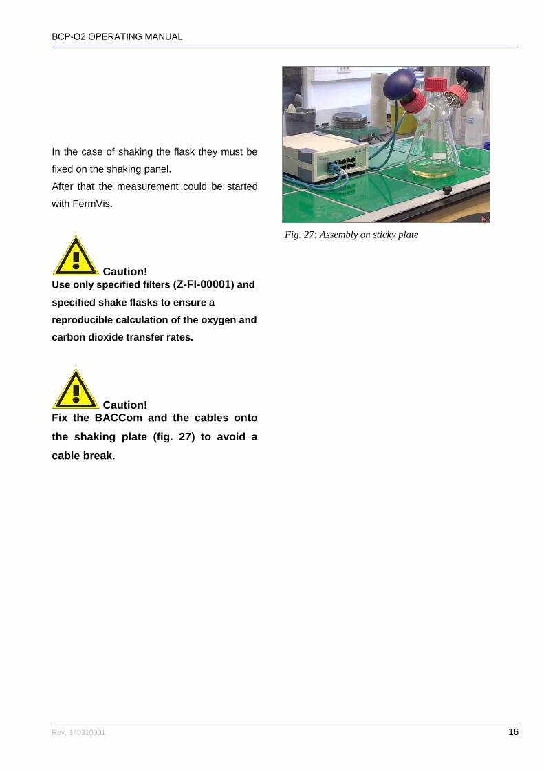
In the case of shaking the flask they must be
fixed on the shaking panel.
After that the measurement could be started
with FermVis.
Caution! Use only specified filters (Z-FI-00001) and
specified shake flasks to ensure a
reproducible calculation of the oxygen and
carbon dioxide transfer rates.
Caution! Fix the BACCom and the cables onto
the shaking plate (fig. 27) to avoid a
cable break.
Fig. 27: Assembly on sticky plate
BCP-O2 OPERATING MANUAL
Rev. 140310001 17
4.3 Electrical connection
4.3.1 General information
Caution!
Read the installation instructions carefully to
prevent damage to the device.
Proceed step-by-step.
Only use the original plugs, cables and power
adapters.
Never connect or disconnect plugs when the
device is connected to the power supply.
The device does not have an on/off switch; it
starts operation as soon as it is connected to
the power supply.
Improper operation can result in damage to the
device.

BCP-O2 OPERATING MANUAL
Rev. 140310001 18
4.3.2 Version 4 – 20 mA in PA6 housing
To connect the measuring device to the connection
cable of the sensor head in the PA6 housing (fig.
28), use the supplied socket and strain relief (fig.
29).
Note!
The numbering of the pins and their assignment
refer to the socket when seen from behind (fig.
30).
Remove the insulation of the cables a little as
possible to avoid short circuits in the plug
housing.
PIN 1 V+ = 12 V
PIN 2 GND
PIN 3 RS232_TXD
PIN 4 RS232_RXD
PIN 5 1-point calibration
PIN 6 4–20mA, RL < 250 Ohm
PIN 7 For internal use only
PIN 8 GND
Fig. 30: Plug assignment
1. Connect the 12 V DC power supply to pin 1 of
the socket.
2. Connect GND (ground) to pin 2.
3. Connect the measuring device to pin 6
(RL < 250 Ohm) and pin 8 GND (ground).
4. Plug the sensor cable into the socket.
After around 1 hour of heating-up time, the sensor
still requires adjusting. During the heating-up time,
the sensor displays 2.3 mA. To make the adjust-
ment, expose the sensor for approx. 30 minutes
(depending on specification – see datasheet) to
ambient air (20.97 Vol. % O2) or process gas
without any biological activity in the reactor.
5. Afterwards, connect pin 5 to pin 8 (GND) for
5 seconds.
Fig. 28 .Fig. 29
BCP-O2 OPERATING MANUAL
Rev. 140310001 19
6. Screw on the strain relief. The sensor has been
adjusted.
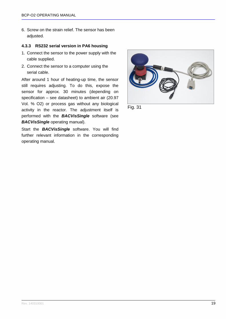
4.3.3 RS232 serial version in PA6 housing
1. Connect the sensor to the power supply with the
cable supplied.
2. Connect the sensor to a computer using the
serial cable.
After around 1 hour of heating-up time, the sensor
still requires adjusting. To do this, expose the
sensor for approx. 30 minutes (depending on
specification – see datasheet) to ambient air (20.97
Vol. % O2) or process gas without any biological
activity in the reactor. The adjustment itself is
performed with the BACVisSingle software (see
BACVisSingle operating manual).
Start the BACVisSingle software. You will find
further relevant information in the corresponding
operating manual.
Fig. 31 Fig
BCP-O2 OPERATING MANUAL
Rev. 140310001 20
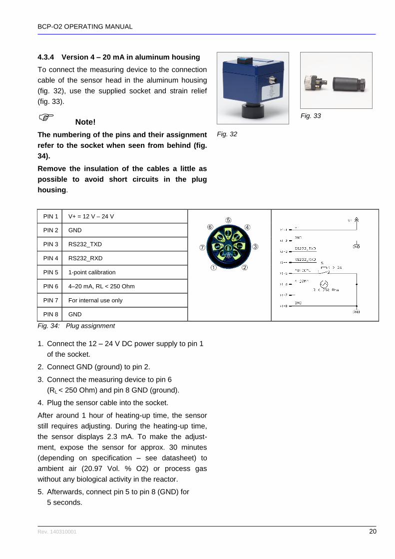
4.3.4 Version 4 – 20 mA in aluminum housing
To connect the measuring device to the connection
cable of the sensor head in the aluminum housing
(fig. 32), use the supplied socket and strain relief
(fig. 33).
Note!
The numbering of the pins and their assignment
refer to the socket when seen from behind (fig.
34).
Remove the insulation of the cables a little as
possible to avoid short circuits in the plug
housing.
PIN 1 V+ = 12 V – 24 V
PIN 2 GND
PIN 3 RS232_TXD
PIN 4 RS232_RXD
PIN 5 1-point calibration
PIN 6 4–20 mA, RL < 250 Ohm
PIN 7 For internal use only
PIN 8 GND
Fig. 34: Plug assignment
1. Connect the 12 – 24 V DC power supply to pin 1
of the socket.
2. Connect GND (ground) to pin 2.
3. Connect the measuring device to pin 6
(RL < 250 Ohm) and pin 8 GND (ground).
4. Plug the sensor cable into the socket.
After around 1 hour of heating-up time, the sensor
still requires adjusting. During the heating-up time,
the sensor displays 2.3 mA. To make the adjust-
ment, expose the sensor for approx. 30 minutes
(depending on specification – see datasheet) to
ambient air (20.97 Vol. % O2) or process gas
without any biological activity in the reactor.
5. Afterwards, connect pin 5 to pin 8 (GND) for
5 seconds.
Fig. 33
Fig. 23
Fig. 21
Fig. 20
Fig. 24
Fig. 28
Fig. 32
Fig
BCP-O2 OPERATING MANUAL
Rev. 140310001 21
6. Screw on the strain relief. The sensor has been
adjusted.
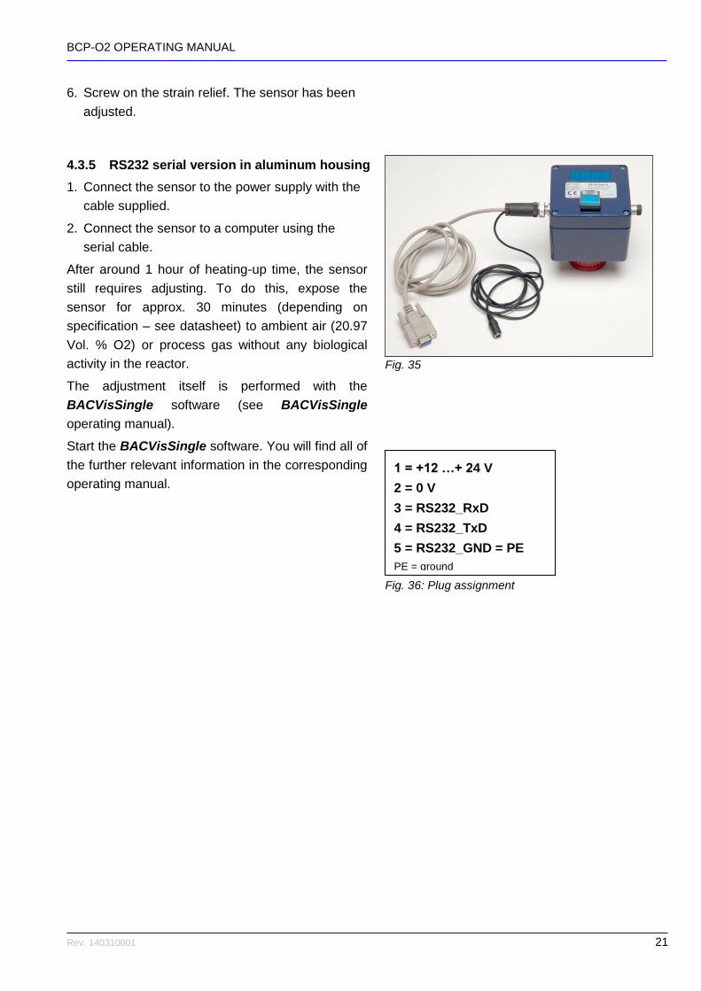
4.3.5 RS232 serial version in aluminum housing
1. Connect the sensor to the power supply with the
cable supplied.
2. Connect the sensor to a computer using the
serial cable.
After around 1 hour of heating-up time, the sensor
still requires adjusting. To do this, expose the
sensor for approx. 30 minutes (depending on
specification – see datasheet) to ambient air (20.97
Vol. % O2) or process gas without any biological
activity in the reactor.
The adjustment itself is performed with the
BACVisSingle software (see BACVisSingle
operating manual).
Start the BACVisSingle software. You will find all of
the further relevant information in the corresponding
operating manual.
1 = +12 …+ 24 V
2 = 0 V
3 = RS232_RxD
4 = RS232_TxD
5 = RS232_GND = PE
PE = ground
Fig. 36: Plug assignment
Fig. 35

BCP-O2 OPERATING MANUAL
Rev. 140310001 22
4.3.6 Connection via BACCom12
The BACCom12 connection box is an electronic
multiplexer with an integrated pressure sensor. It
facilitates the connection of up to 12 sensor heads.
Communication with a PC can be switched between
RS232 or Ethernet.
The individual connections are explained in the
following table:
Designation Description
A RJ45 RJ45 socket for connecting the sensors
B LED Operating display when a voltage is present
C Sub D 9 pin Data transmission to the PC
D Switch Switches between RS232 and Ethernet
F RJ45 Ethernet connection
G Power socket
12 V 3.75 A, only use the supplied power adapter
H Box reset Resets the box; does not effect the sensors
K M8 4 pin socket
4-pin connection sockets A–D for additional boxes
Caution!
To prevent damage to the device, only use the
supplied power adapter and the supplied cable.
Never disconnect or connect the connection
plugs on the sensor heads when the BACCom12
is switched on.
1. Connect all sensor heads with the BACCom12.
2. Connect the supplied power adapter to the power
socket G.
3. Plug the power plug of the power adapter into the
socket.
After a heating-up time of approx. 1 hour, the
measuring system is ready for operation.
Fig. 38: Connections on the BACCom12
Fig. 37: Front of the BACCom12
BCP-O2 OPERATING MANUAL
Rev. 140310001 23
4. Connect the BACCom12 to the PC or network
via the Ethernet port E,
or connect the
BACCom12 via the RS232 output C with the
supplied cable to the serial interface of the
computer.
5. Select the corresponding interface with the
switch D.
After around 1 hour of heating-up time, the sensor
still requires adjusting. To do this, expose the
sensor for approx. 30 minutes (depending on
specification – see datasheet) to ambient air (20.97
Vol. % O2) or humid process gas without any
biological activity in the reactor.
Adjustment of the sensors is performed with the
BACVis software. Start the corresponding software.
You will find all further information in the software
instructions.
After initial commissioning, the measuring device
can remain switched on constantly, meaning that
the heating-up time is not required before every
measuring.
4.4 Minimization of dilution effects through humidity
To minimize the effect of dilution through
accumulating water molecules in the dry process
gas, the oxygen sensors could be adjusted with
humid process gas (20.97 Vol. % O2) (at working
temperature) instead of ambient air.

BCP-O2 OPERATING MANUAL
Rev. 140310001 24
5 Maintenance We recommend sending the device to BlueSens for
annual maintenance, checking and calibration of the
sensors. If the sensor is not used under power no
aging occurs. In this case it has to be stored under
conditions of ambient air (humidity smaller than
75%).
5.1 1-point calibration
Once monthly, or after each connection and
disconnection of the sensor head and measuring
adapter, the sensor head must be exposed for
approx. 30 minutes (depending on specifications,
see datasheet) to ambient air (20.97 Vol.% O2) or
humid process gas without any biological activity in
the reactor.
Afterwards, connect pin 5 to pin 8 on the connection
cable for 5 seconds, or, if present on the sensor,
press the blue button for 5 seconds (fig. 39).
For the serial version, the adjustment can be made
using the BACVis/BACVisSingle or the FermVis
software.
5.2 Recalibration
The sensor should be sent back to the manufacturer
or an authorized dealer for annual recalibration.
You can get further information for our annual
maintenance service Blue4Care incl. extension of
the warranty up to 6 years on:
http://www.bluesens.de/fileadmin/dl/Blue4Care.pdf
or just go to:
www.bluesens.com Service/Downloads
to find the latest information about Blue4Care.
Fig. 39
BCP-O2 OPERATING MANUAL
Rev. 140310001 25
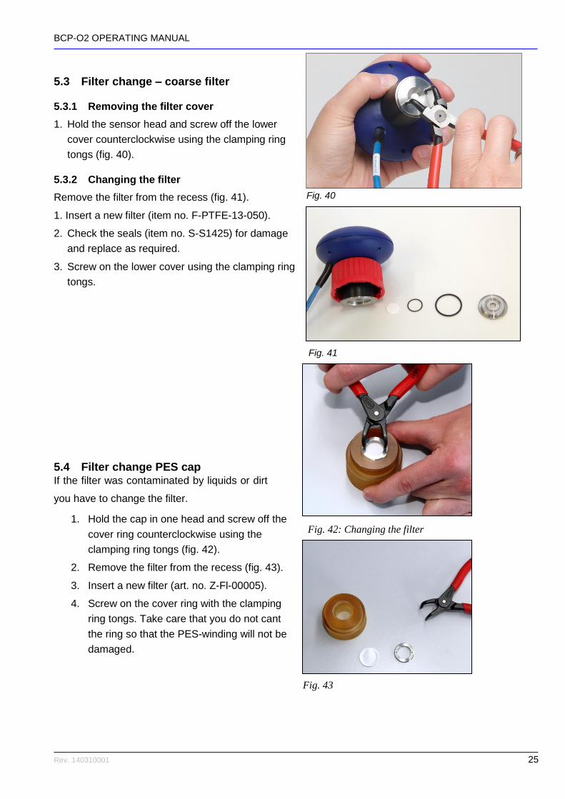
5.3 Filter change – coarse filter
5.3.1 Removing the filter cover
1. Hold the sensor head and screw off the lower
cover counterclockwise using the clamping ring
tongs (fig. 40).
5.3.2 Changing the filter
Remove the filter from the recess (fig. 41).
1. Insert a new filter (item no. F-PTFE-13-050).
2. Check the seals (item no. S-S1425) for damage
and replace as required.
3. Screw on the lower cover using the clamping ring
tongs.
5.4 Filter change PES cap If the filter was contaminated by liquids or dirt
you have to change the filter.
1. Hold the cap in one head and screw off the
cover ring counterclockwise using the
clamping ring tongs (fig. 42).
2. Remove the filter from the recess (fig. 43).
3. Insert a new filter (art. no. Z-Fl-00005).
4. Screw on the cover ring with the clamping
ring tongs. Take care that you do not cant
the ring so that the PES-winding will not be
damaged.
Fig. 40
Fig. 41
Fig. 43
Fig. 42: Changing the filter

BCP-O2 OPERATING MANUAL
Rev. 140310001 26
6 Appendix
6.1 Calibration table
Complete calibration can only be conducted by BlueSens. Monthly 1-point calibration can be performed
as described in chapter 5.1. The adjustment must also be made each time the sensor head and the
measuring adapter are disconnected from each other.
Fill out the table below when this is performed.
Date Procedure Conditions Name Signature
Complete calibration 25 °C, 1 bar BlueSens
1-point calibration

BCP-O2 OPERATING MANUAL
Rev. 140310001 27
6.2 Technical data
See enclosed datasheet.

BCP-O2 OPERATING MANUAL
Rev. 140310001 28
Blue4Care - The maintenance service by BlueSens
BlueSens’ gas sensors are high quality measuring devices. To ensure accurate operation and to extend the guarantee for one year we recommend annual maintenance in our factory. Blue4Care is a full service package for your BlueSens gas sensors. It´s not necessary to order and pay for the service directly with your sensor order. Within one year after the sale of the sensor we will inform you and offer the service to you. If you decide for Blue4Care, we will book a date for the maintenance and calibration of your sensors. The typical timeframe to complete the service will be one week exclusive shipping time. If you service your sensor annually using Blue4Care, the devices will remain in our extended guarantee scheme. This means that, excluding user damage, your sensor will keep its original guarantee for years with significantly reduced maintenance costs. You may also request at any time “maintenance on demand”. BlueSens will repair or replace broken parts and calibrate the sensor as required by the user. Maintenance on demand does not extend the guarantee Advantages:
Maintenance administration by BlueSens
Payment and Order one year after purchase
Reduce Rate compare to ”Maintenance on demand”
Fixed cost per year
Annual extension of guarantee for one year after maintenance (up to 6 years)
Cost: Please visit the service-area on our homepage for prices:
www.bluesens.com Service/Downloads
BCP-O2 OPERATING MANUAL
Rev. 140310001 29
EG-Konformitätserklärung EC Declaration of conformity
Hiermit erklären wir, dass unser Produkt, Typ:
We hereby declare that our product, type;
BCP-O2
folgenden einschlägigen Bestimmungen entspricht:
complies with the following relevant provisions:
Niederspannungsrichtlinie (72/23/EWG und 93/68/EWG) findet keine Anwendung, da keine
Spannung größer 24 V genutzt wird.
Low voltage guideline (72/23/EEC and 93/68/EEC) is not applicable as no voltage higher than
24 V is used.
EMV-Richtlinie (89/336/EWG, 92/31/EWG und 93/68/EWG)
EMC guideline (89/336/EEC, 92/31/EEC and 93/68/EEC)
Angewendete harmonisierte Normen, insbesondere:
Applied harmonized standards, in particular:
EN50081–1 EN61000 Dr. Holger Mueller, Dr. Udo Schmale BlueSens gas sensor GmbH Snirgelskamp 25 D-45699 Herten, Germany Phone +492366 / 4995-500 Fax +492366 / 4995-599 Dr. Udo Schmale www.bluesens.com