Embed Size (px)
Citation preview
Operating Manual
motrona GmbH, Zeppelinstraße 16, DE - 78244 Gottmadingen, Tel. +49 (0) 7731 9332-0, Fax +49 (0) 7731 9332-30, [email protected], www.motrona.com
UZ210 Universal signal converter: Analog (V/mA) - Incremental / SSI / RS232 / RS485
Product Features:
Analog input for voltage, current or potentiometer operation
Operation as frequency converter/-generator, positional / angular encoder or data
logging possible
Programmable curves with optionally repeating curve cycles
Frequency output (HTL or TTL level, max. 1 MHz) proportional to the input signal
Incremental output and SSI interface, for digital expression of linear or angular positions
Incremental direction signal A, B under control of input signal and parameter settings
Additional control functions similar to a motorized potentiometer
USB programming port and serial interface (RS232 / RS485)
Programmable marker resp. index pulse output (Z, /Z)
Power supply 12 to 30 VDC
Uz210_02c_oi_e.doc / Apr-16 Page 2 / 27
Version: Description:
UZ21001a_af_hk/Feb12 First edition
UZ21002a_af_hk/Jul12 Extensions for communication via USB port
Uz210_02b_af_sn/Dec14 Extensions for inhibit-function
Uz210_02c_oi_/Dez-15/ag Safety Instructions, Legal Notices and design added resp. updated.
Connection diagram: mistake eliminated (X4/1 = GND instead of AGND).
Analog in drawings: mistake eliminated (AGND = X4/6 instead of X4/1).
Addition (Techn. Specifications): “SSI - only single transmission supported”.
Hint supplemented: Only RS232 or RS485 (not both at the same time).
Legal notices:
All contents included in this manual are protected by the terms of use and copyrights of motrona GmbH. Any
reproduction, modification, usage or publication in other electronic and printed media as well as in the internet
requires prior written authorization by motrona GmbH.
Uz210_02c_oi_e.doc / Apr-16 Page 3 / 27
Table of Contents
1. Safety Instructions and Responsibility ......................................................... 4
1.1 General Safety Instructions ............................................................................................. 4 1.2 Use according to the intended purpose........................................................................... 4 1.3 Installation ....................................................................................................................... 5 1.4 Cleaning, Maintenance and Service Notes ..................................................................... 5
2. Introduction ................................................................................................. 6
2.1. Operation as Signal Converter......................................................................................... 7 2.2. Operation as Frequency or Position Generator (Motorized Potentiometer Mode) ....... 7
3. Typical Examples of Application .................................................................. 8
3.1. UZ 210 as Analogue-to-Frequency Converter or Generator ............................................ 8 3.2. UZ 210 as Positional or Angular Encoder with Analogue Input ...................................... 9 3.3. UZ 210 for PC Applications (Data Logging) ..................................................................... 9
4. Connections and Control Elements ............................................................ 10
4.1. Power Supply ................................................................................................................. 10 4.2. Control Inputs Control1 - Control4 ................................................................................. 11 4.3. The SSI Interface ........................................................................................................... 11 4.4. Analogue Inputs ............................................................................................................. 12 4.5. Incremental Outputs ...................................................................................................... 12 4.6. The Serial Interface ....................................................................................................... 13 4.7. The USB Communication Port ........................................................................................ 14 4.8. The Front DIL Switch and the Front LEDs ...................................................................... 14
5. Parameter Settings .................................................................................... 15
5.1. General Settings ............................................................................................................ 16 5.2. Analogue Settings (Analogue Input).............................................................................. 17 5.3. SSI Setting (SSI Data Transmission) ............................................................................. 17 5.4. Encoder Setting (Incremental Output) ........................................................................... 18 5.5. Command Setting (Control Inputs)................................................................................. 18 5.6. Serial Setting (RS232/RS485 Interface) ........................................................................ 19 5.7. Linearization Setting ...................................................................................................... 20 5.8. Hints for Use oft the Linearization Function .................................................................. 20
6. Hints for Serial Communication ................................................................. 21
6.1. Automatic and Cyclic Data Transmission ...................................................................... 21 6.2. Communication Protocol ................................................................................................ 22
7. Hints for Operation of the USB Port ........................................................... 24
8. Technical Specifications ............................................................................ 26
9. Dimensions ................................................................................................ 27
Uz210_02c_oi_e.doc / Apr-16 Page 4 / 27
1. Safety Instructions and Responsibility
1.1 General Safety Instructions This operation manual is a significant component of the unit and includes important rules and
hints about the installation, function and usage. Non-observance can result in damage and/or
impairment of the functions to the unit or the machine or even in injury to persons using the
equipment!
Please read the following instructions carefully before operating the device and observe all
safety and warning instructions! Keep the manual for later use.
A pertinent qualification of the respective staff is a fundamental requirement in order to use
these manual. The unit must be installed, connected and put into operation by a qualified
electrician.
Liability exclusion: The manufacturer is not liable for personal injury and/or damage to property
and for consequential damage, due to incorrect handling, installation and operation. Further
claims, due to errors in the operation manual as well as misinterpretations are excluded from
liability.
In addition the manufacturer reserve the right to modify the hardware, software or operation
manual at any time and without prior notice. Therefore, there might be minor differences
between the unit and the descriptions in operation manual.
The raiser respectively positioner is exclusively responsible for the safety of the system and
equipment where the unit will be integrated.
During installation or maintenance all general and also all country- and application-specific
safety rules and standards must be observed.
If the device is used in processes, where a failure or faulty operation could damage the system
or injure persons, appropriate precautions to avoid such consequences must be taken.
1.2 Use according to the intended purpose The unit is intended exclusively for use in industrial machines, constructions and systems. Non-
conforming usage does not correspond to the provisions and lies within the sole responsibility
of the user. The manufacturer is not liable for damages which has arisen through unsuitable
and improper use.
Please note that device may only be installed in proper form and used in a technically perfect
condition - in accordance to the Technical Specifications (see chapter 8). The device is not
suitable for operation in explosion-proof areas or areas which are excluded by the EN 61010-1
standard.

Uz210_02c_oi_e.doc / Apr-16 Page 5 / 27
1.3 Installation The device is only allowed to be installed and operated within the permissible temperature
range. Please ensure an adequate ventilation and avoid all direct contact between the device
and hot or aggressive gases and liquids.
Before installation or maintenance, the unit must be disconnected from all voltage-sources.
Further it must be ensured that no danger can arise by touching the disconnected voltage-
sources.
Devices which are supplied by AC-voltages, must be connected exclusively by switches,
respectively circuit-breakers with the low voltage network. The switch or circuit-breaker must
be placed as near as possible to the device and further indicated as separator.
Incoming as well as outgoing wires and wires for extra low voltages (ELV) must be separated
from dangerous electrical cables (SELV circuits) by using a double resp. increased isolation.
All selected wires and isolations must be conform to the provided voltage- and temperature-
ranges. Further all country- and application-specific standards, which are relevant for structure,
form and quality of the wires, must be ensured. Indications about the permissible wire cross-
sections for wiring are described in the Technical Specifications (see chapter 8).
Before first start-up it must be ensured that all connections and wires are firmly seated and
secured in the screw terminals. All (inclusively unused) terminals must be fastened by turning
the relevant screws clockwise up to the stop.
Overvoltages at the connections must be limited to values in accordance to the overvoltage
category II.
For placement, wiring, environmental conditions as well as shielding and earthing/grounding of
the supply lines the general standards of industrial automation industry and the specific
shielding instructions of the manufacturer are valid. Please find all respective hints and rules on
www.motrona.com/download.html --> “[General EMC Rules for Wiring, Screening and
Earthing]”.
1.4 Cleaning, Maintenance and Service Notes To clean the front of the unit please use only a slightly damp (not wet!), soft cloth. For the rear
no cleaning is necessary. For an unscheduled, individual cleaning of the rear the maintenance
staff or assembler is self-responsible.
During normal operation no maintenance is necessary. In case of unexpected problems, failures
or malfunctions the device must be shipped for back to the manufacturer for checking,
adjustment and reparation (if necessary). Unauthorized opening and repairing can have
negative effects or failures to the protection-measures of the unit.
Uz210_02c_oi_e.doc / Apr-16 Page 6 / 27
2. Introduction
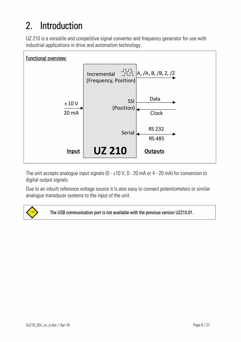
UZ 210 is a versatile and competitive signal converter and frequency generator for use with
industrial applications in drive and automation technology.
Functional overview:
UZ 210
10 V
20 mA
A, /A, B, /B, Z, /Z(Frequency, Position)
Data
Clock
Incremental
SSI(Position)
SerialRS 232
RS 485
Input Outputs
The unit accepts analogue input signals (0 - ±10 V, 0 - 20 mA or 4 - 20 mA) for conversion to
digital output signals.
Due to an inbuilt reference voltage source it is also easy to connect potentiometers or similar
analogue transducer systems to the input of the unit.
The USB communication port is not available with the previous version UZ210.01.
Uz210_02c_oi_e.doc / Apr-16 Page 7 / 27
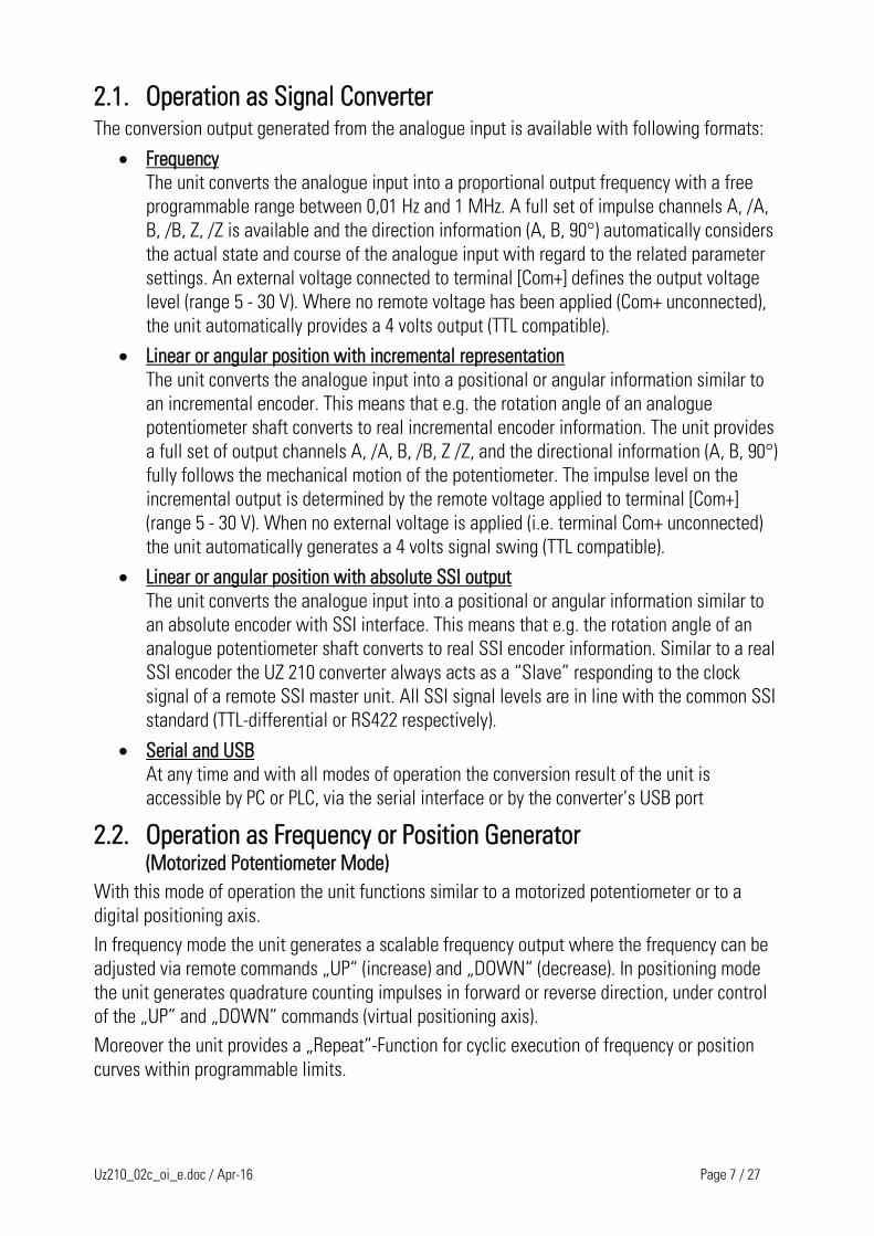
2.1. Operation as Signal Converter The conversion output generated from the analogue input is available with following formats:
Frequency
The unit converts the analogue input into a proportional output frequency with a free
programmable range between 0,01 Hz and 1 MHz. A full set of impulse channels A, /A,
B, /B, Z, /Z is available and the direction information (A, B, 90°) automatically considers
the actual state and course of the analogue input with regard to the related parameter
settings. An external voltage connected to terminal [Com+] defines the output voltage
level (range 5 - 30 V). Where no remote voltage has been applied (Com+ unconnected),
the unit automatically provides a 4 volts output (TTL compatible).
Linear or angular position with incremental representation
The unit converts the analogue input into a positional or angular information similar to
an incremental encoder. This means that e.g. the rotation angle of an analogue
potentiometer shaft converts to real incremental encoder information. The unit provides
a full set of output channels A, /A, B, /B, Z /Z, and the directional information (A, B, 90°)
fully follows the mechanical motion of the potentiometer. The impulse level on the
incremental output is determined by the remote voltage applied to terminal [Com+]
(range 5 - 30 V). When no external voltage is applied (i.e. terminal Com+ unconnected)
the unit automatically generates a 4 volts signal swing (TTL compatible).
Linear or angular position with absolute SSI output
The unit converts the analogue input into a positional or angular information similar to
an absolute encoder with SSI interface. This means that e.g. the rotation angle of an
analogue potentiometer shaft converts to real SSI encoder information. Similar to a real
SSI encoder the UZ 210 converter always acts as a “Slave” responding to the clock
signal of a remote SSI master unit. All SSI signal levels are in line with the common SSI
standard (TTL-differential or RS422 respectively).
Serial and USB
At any time and with all modes of operation the conversion result of the unit is
accessible by PC or PLC, via the serial interface or by the converter’s USB port
2.2. Operation as Frequency or Position Generator (Motorized Potentiometer Mode) With this mode of operation the unit functions similar to a motorized potentiometer or to a
digital positioning axis.
In frequency mode the unit generates a scalable frequency output where the frequency can be
adjusted via remote commands „UP“ (increase) and „DOWN“ (decrease). In positioning mode
the unit generates quadrature counting impulses in forward or reverse direction, under control
of the „UP“ and „DOWN“ commands (virtual positioning axis).
Moreover the unit provides a „Repeat“-Function for cyclic execution of frequency or position
curves within programmable limits.
Uz210_02c_oi_e.doc / Apr-16 Page 8 / 27
3. Typical Examples of Application
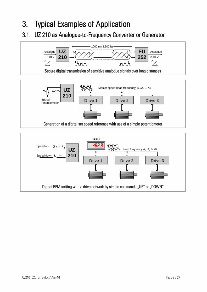
3.1. UZ 210 as Analogue-to-Frequency Converter or Generator
UZ210
Analogue
+/-10 V
FU252
Analogue
+/-10 V
1000 m (3,300 ft)
Secure digital transmission of sensitive analogue signals over long distances
UZ210UZ210
Drive 1 Drive 3Drive 2
Master speed (lead frequency) A, /A, B, /B
SpeedPotentiometer
+/-10V
Generation of a digital set speed reference with use of a simple potentiometer
UZ210UZ210
Drive 1 Drive 3Drive 2
Lead frequency A, /A, B, /B+++
---
Speed up
Speed down
RPM
Digital RPM setting with a drive network by simple commands „UP“ or „DOWN“
Uz210_02c_oi_e.doc / Apr-16 Page 9 / 27
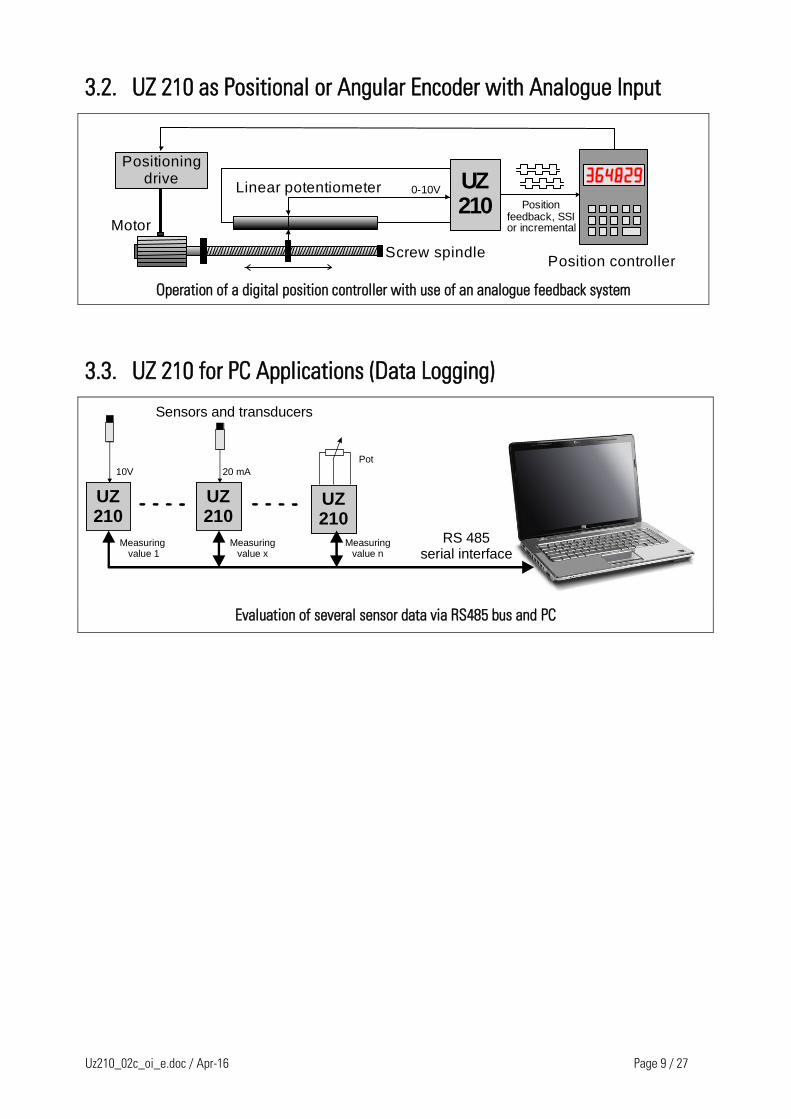
3.2. UZ 210 as Positional or Angular Encoder with Analogue Input
Positioningdrive UZ
210UZ210
Motor
Screw spindle
Linear potentiometerPosition
feedback, SSIor incremental
0-10V
Position controller
Operation of a digital position controller with use of an analogue feedback system
3.3. UZ 210 for PC Applications (Data Logging)
UZ210UZ210
UZ210UZ210
UZ210UZ210
10V 20 mA
Pot
Sensors and transducers
RS 485serial interface
Measuring value 1
Measuringvalue x
Measuringvalue n
Evaluation of several sensor data via RS485 bus and PC
Uz210_02c_oi_e.doc / Apr-16 Page 10 / 27
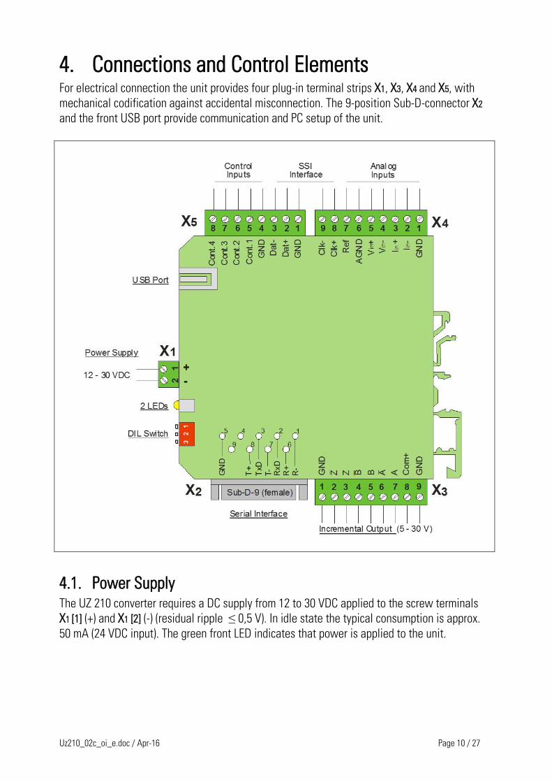
4. Connections and Control Elements For electrical connection the unit provides four plug-in terminal strips X1, X3, X4 and X5, with
mechanical codification against accidental misconnection. The 9-position Sub-D-connector X2
and the front USB port provide communication and PC setup of the unit.
4.1. Power Supply The UZ 210 converter requires a DC supply from 12 to 30 VDC applied to the screw terminals
X1 [1] (+) and X1 [2] (-) (residual ripple ≤ 0,5 V). In idle state the typical consumption is approx.
50 mA (24 VDC input). The green front LED indicates that power is applied to the unit.
Uz210_02c_oi_e.doc / Apr-16 Page 11 / 27
4.2. Control Inputs Control1 - Control4 Four control inputs with programmable function are accessible via terminals X5 [5, 6, 7, 8]. The
desired function can be assigned by the parameters [Input Config.] and [Input Function] of the
„Command Setting“ menu.[a]
All control inputs are designed as PNP inputs, i.e. a positive voltage must be applied with
reference to GND. The switching thresholds are LOW ≤ 3 V and HIGH ≥ 10 V, and the input
impedance is about 15 kΩ.
GND
Cont. 1 - 4
Principal of a control input circuit
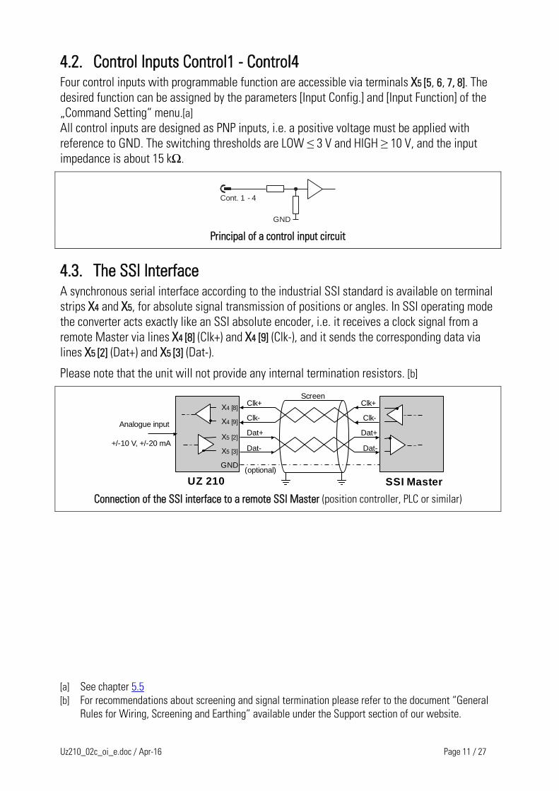
4.3. The SSI Interface A synchronous serial interface according to the industrial SSI standard is available on terminal
strips X4 and X5, for absolute signal transmission of positions or angles. In SSI operating mode
the converter acts exactly like an SSI absolute encoder, i.e. it receives a clock signal from a
remote Master via lines X4 [8] (Clk+) and X4 [9] (Clk-), and it sends the corresponding data via
lines X5 [2] (Dat+) and X5 [3] (Dat-).
Please note that the unit will not provide any internal termination resistors. [b]
SSI MasterUZ 210
Clk+ Clk+
Clk- Clk-
Dat+ Dat+
Dat- Dat-
Screen
Analogue input
X 4 [8]
X 4 [9]
X 5 [2]
X 5 [3]
GND(optional)
+/-10 V, +/-20 mA
Connection of the SSI interface to a remote SSI Master (position controller, PLC or similar)
[a] See chapter 5.5
[b] For recommendations about screening and signal termination please refer to the document “General
Rules for Wiring, Screening and Earthing” available under the Support section of our website.
Uz210_02c_oi_e.doc / Apr-16 Page 12 / 27
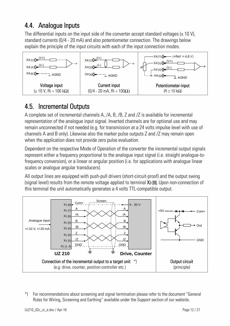
4.4. Analogue Inputs The differential inputs on the input side of the converter accept standard voltages (± 10 V),
standard currents (0/4 - 20 mA) and also potentiometer connection. The drawings below
explain the principle of the input circuits with each of the input connection modes.
Voltage input
(± 10 V, Ri = 100 kΩ)
Current input
(0/4 - 20 mA, Ri = 100Ω)
Potentiometer-input (R ≥ 10 kΩ)
4.5. Incremental Outputs A complete set of incremental channels A, /A, B, /B, Z and /Z is available for incremental
representation of the analogue input signal. Inverted channels are for optional use and may
remain unconnected if not needed (e.g. for transmission at a 24 volts impulse level with use of
channels A and B only). Likewise also the marker pulse outputs Z and /Z may remain open
when the application does not provide zero pulse evaluation.
Dependent on the respective Mode of Operation of the converter the incremental output signals
represent either a frequency proportional to the analogue input signal (i.e. straight analogue-to-
frequency conversion), or a linear or angular position (i.e. for applications with analogue linear
scales or analogue angular transducers).
All output lines are equipped with push-pull drivers (short-circuit-proof) and the output swing
(signal level) results from the remote voltage applied to terminal X3 [8]. Upon non-connection of
this terminal the unit automatically generates a 4 volts TTL-compatible output.
Drive, CounterUZ 210
Screen
Analogue inputX 3 [5]
X 3 [4]
X 3 [3]
X 3 [2]
GND
X 3 [7]
X 3 [6]
A
/A
B
/B
Z
/Z
A
/A
B
/B
Z
/Z
X 3 [1, 9]
X 3 [8]
GND
Com+5 - 30 V
+/-10 V, +/-20 mA
Com+
Out
GND
+5V internal
Connection of the incremental output to a target unit *)
(e.g. drive, counter, position controller etc.)
Output circuit
(principle)
*) For recommendations about screening and signal termination please refer to the document “General
Rules for Wiring, Screening and Earthing” available under the Support section of our website.
Uz210_02c_oi_e.doc / Apr-16 Page 13 / 27
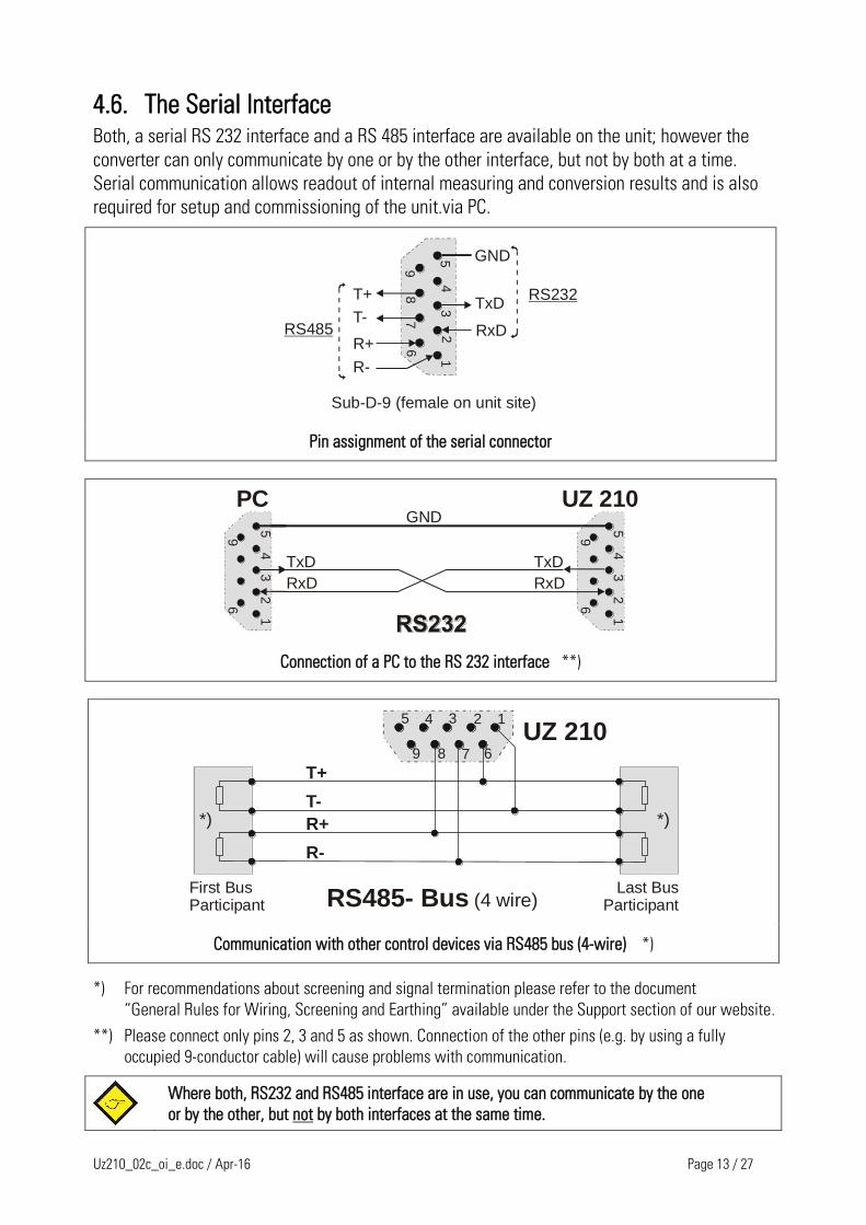
4.6. The Serial Interface Both, a serial RS 232 interface and a RS 485 interface are available on the unit; however the
converter can only communicate by one or by the other interface, but not by both at a time.
Serial communication allows readout of internal measuring and conversion results and is also
required for setup and commissioning of the unit.via PC.
54
32
1
98
76
GND
TxD
RxD
RS232T+
T-
R+
R-
RS485
Sub-D-9 (female on unit site)
Pin assignment of the serial connector
54
32
1
98
76
54
32
1
96
54
32
1
98
76
54
32
1
96
GND
TxD
RxD
PC UZ 210
TxD
RxD
Connection of a PC to the RS 232 interface **)
T+
T-
RS485- Bus (4 wire)
R+
R-
5 4 3 2 1
9 8 7 6
UZ 210
First BusParticipant
Last BusParticipant
*) *)
Communication with other control devices via RS485 bus (4-wire) *)
*) For recommendations about screening and signal termination please refer to the document
“General Rules for Wiring, Screening and Earthing” available under the Support section of our website.
**) Please connect only pins 2, 3 and 5 as shown. Connection of the other pins (e.g. by using a fully
occupied 9-conductor cable) will cause problems with communication.
Where both, RS232 and RS485 interface are in use, you can communicate by the one
or by the other, but not by both interfaces at the same time.
Uz210_02c_oi_e.doc / Apr-16 Page 14 / 27
T+
T-
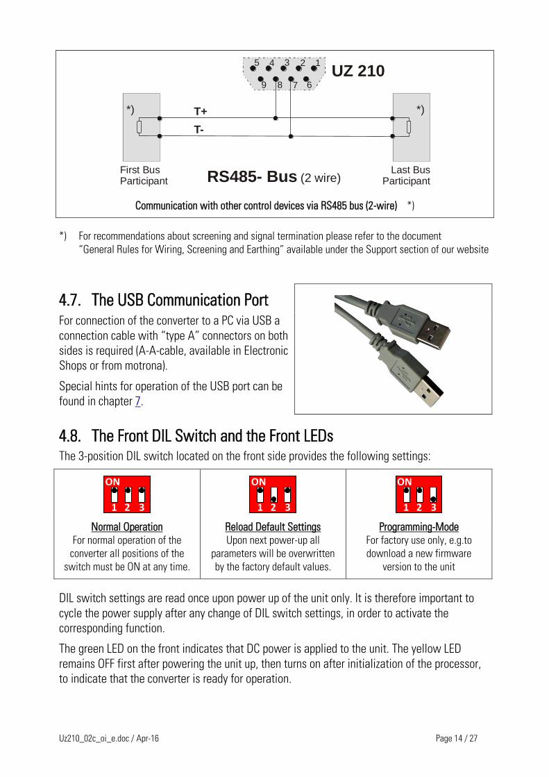
RS485- Bus (2 wire)
5 4 3 2 1
9 8 7 6
UZ 210
First BusParticipant
Last BusParticipant
*) *)
Communication with other control devices via RS485 bus (2-wire) *)
*) For recommendations about screening and signal termination please refer to the document
“General Rules for Wiring, Screening and Earthing” available under the Support section of our website
4.7. The USB Communication Port
For connection of the converter to a PC via USB a
connection cable with “type A” connectors on both
sides is required (A-A-cable, available in Electronic
Shops or from motrona).
Special hints for operation of the USB port can be
found in chapter 7.
4.8. The Front DIL Switch and the Front LEDs The 3-position DIL switch located on the front side provides the following settings:
1 2 3
ON
1 2 3
ON
1 2 3
ON
Normal Operation
For normal operation of the
converter all positions of the
switch must be ON at any time.
Reload Default Settings
Upon next power-up all
parameters will be overwritten
by the factory default values.
Programming-Mode
For factory use only, e.g.to
download a new firmware
version to the unit
DIL switch settings are read once upon power up of the unit only. It is therefore important to
cycle the power supply after any change of DIL switch settings, in order to activate the
corresponding function.
The green LED on the front indicates that DC power is applied to the unit. The yellow LED
remains OFF first after powering the unit up, then turns on after initialization of the processor,
to indicate that the converter is ready for operation.
Uz210_02c_oi_e.doc / Apr-16 Page 15 / 27
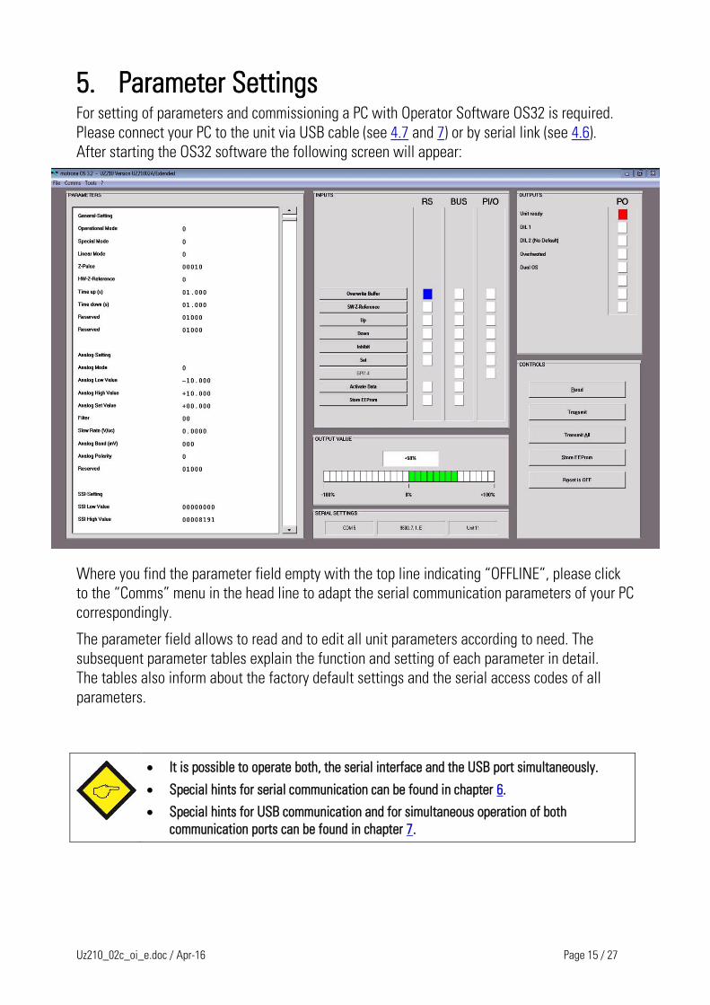
5. Parameter Settings For setting of parameters and commissioning a PC with Operator Software OS32 is required.
Please connect your PC to the unit via USB cable (see 4.7 and 7) or by serial link (see 4.6).
After starting the OS32 software the following screen will appear:
Where you find the parameter field empty with the top line indicating “OFFLINE”, please click
to the “Comms” menu in the head line to adapt the serial communication parameters of your PC
correspondingly.
The parameter field allows to read and to edit all unit parameters according to need. The
subsequent parameter tables explain the function and setting of each parameter in detail.
The tables also inform about the factory default settings and the serial access codes of all
parameters.
It is possible to operate both, the serial interface and the USB port simultaneously.
Special hints for serial communication can be found in chapter 6.
Special hints for USB communication and for simultaneous operation of both
communication ports can be found in chapter 7.
Uz210_02c_oi_e.doc / Apr-16 Page 16 / 27
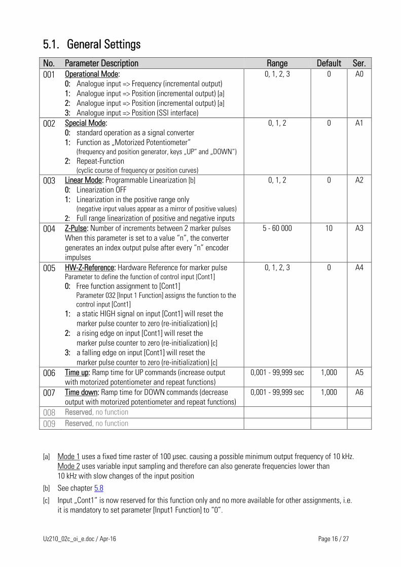
5.1. General Settings
No. Parameter Description Range Default Ser.
001 Operational Mode:
0: Analogue input => Frequency (incremental output)
1: Analogue input => Position (incremental output) [a]
2: Analogue input => Position (incremental output) [a]
3: Analogue input => Position (SSI interface)
0, 1, 2, 3 0 A0
002 Special Mode:
0: standard operation as a signal converter
1: Function as „Motorized Potentiometer“ (frequency and position generator, keys „UP“ and „DOWN“)
2: Repeat-Function (cyclic course of frequency or position curves)
0, 1, 2 0 A1
003 Linear Mode: Programmable Linearization [b]
0: Linearization OFF
1: Linearization in the positive range only (negative input values appear as a mirror of positive values)
2: Full range linearization of positive and negative inputs
0, 1, 2 0 A2
004 Z-Pulse: Number of increments between 2 marker pulses
When this parameter is set to a value “n”, the converter
generates an index output pulse after every “n” encoder
impulses
5 - 60 000 10 A3
005 HW-Z-Reference: Hardware Reference for marker pulse Parameter to define the function of control input [Cont1]
0: Free function assignment to [Cont1] Parameter 032 [Input 1 Function] assigns the function to the
control input [Cont1]
1: a static HIGH signal on input [Cont1] will reset the
marker pulse counter to zero (re-initialization) [c]
2: a rising edge on input [Cont1] will reset the
marker pulse counter to zero (re-initialization) [c]
3: a falling edge on input [Cont1] will reset the
marker pulse counter to zero (re-initialization) [c]
0, 1, 2, 3 0 A4
006 Time up: Ramp time for UP commands (increase output
with motorized potentiometer and repeat functions)
0,001 - 99,999 sec 1,000 A5
007 Time down: Ramp time for DOWN commands (decrease
output with motorized potentiometer and repeat functions)
0,001 - 99,999 sec 1,000 A6
008 Reserved, no function
009 Reserved, no function
[a] Mode 1 uses a fixed time raster of 100 µsec. causing a possible minimum output frequency of 10 kHz.
Mode 2 uses variable input sampling and therefore can also generate frequencies lower than
10 kHz with slow changes of the input position
[b] See chapter 5.8
[c] Input „Cont1“ is now reserved for this function only and no more available for other assignments, i.e.
it is mandatory to set parameter [Input1 Function] to “0”.
Uz210_02c_oi_e.doc / Apr-16 Page 17 / 27
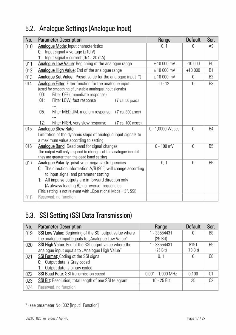
5.2. Analogue Settings (Analogue Input)
No. Parameter Description Range Default Ser.
010 Analogue Mode: Input characteristics
0: Input signal = voltage (±10 V)
1: Input signal = current (0/4 - 20 mA)
0, 1 0 A9
011 Analogue Low Value: Beginning of the analogue range ± 10 000 mV -10 000 B0
012 Analogue High Value: End of the analogue range ± 10 000 mV +10 000 B1
013 Analogue Set Value: Preset value for the analogue input *) ± 10 000 mV 0 B2
014 Analogue Filter: Filter function for the analogue input (used for smoothing of unstable analogue input signals)
00: Filter OFF (immediate response)
01: Filter LOW, fast response (Τ ca. 50 µsec)
---
05: Filter MEDIUM. medium response (Τ ca. 800 µsec)
---
12: Filter HIGH, very slow response (Τ ca. 100 msec)
0 - 12 0 B3
015 Analogue Slew Rate:
Limitation of the dynamic slope of analogue input signals to
a maximum value according to setting
0 - 1,0000 V/µsec 0 B4
016 Analogue Band: Dead band for signal changes The output will only respond to changes of the analogue input if
they are greater than the dead band setting
0 - 100 mV 0 B5
017 Analogue Polarity: positive or negative frequencies
0: The direction information A/B (90°) will change according
to input signal and parameter setting
1: All impulse outputs are in forward direction only
(A always leading B), no reverse frequencies (This setting is not relevant with „Operational Mode = 3“, SSI)
0, 1 0 B6
018 Reserved, no function
5.3. SSI Setting (SSI Data Transmission)
No. Parameter Description Range Default Ser.
019 SSI Low Value: Beginning of the SSI output value where
the analogue input equals to „Analogue Low Value“
1 - 33554431
(25 Bit)
0 B8
020 SSI High Value: End of the SSI output value where the
analogue input equals to „Analogue High Value“
1 - 33554431 (25 Bit)
8191 (13 Bit)
B9
021 SSI Format: Coding ot the SSI signal
0: Output data is Gray coded
1: Output data is binary coded
0, 1 0 C0
022 SSI Baud Rate: SSI transmission speed 0,001 - 1,000 MHz 0,100 C1
023 SSI Bit: Resolution, total length of one SSI telegram 10 - 25 Bit 25 C2
024 Reserved, no function
*) see parameter No. 032 [Input1 Function]
Uz210_02c_oi_e.doc / Apr-16 Page 18 / 27
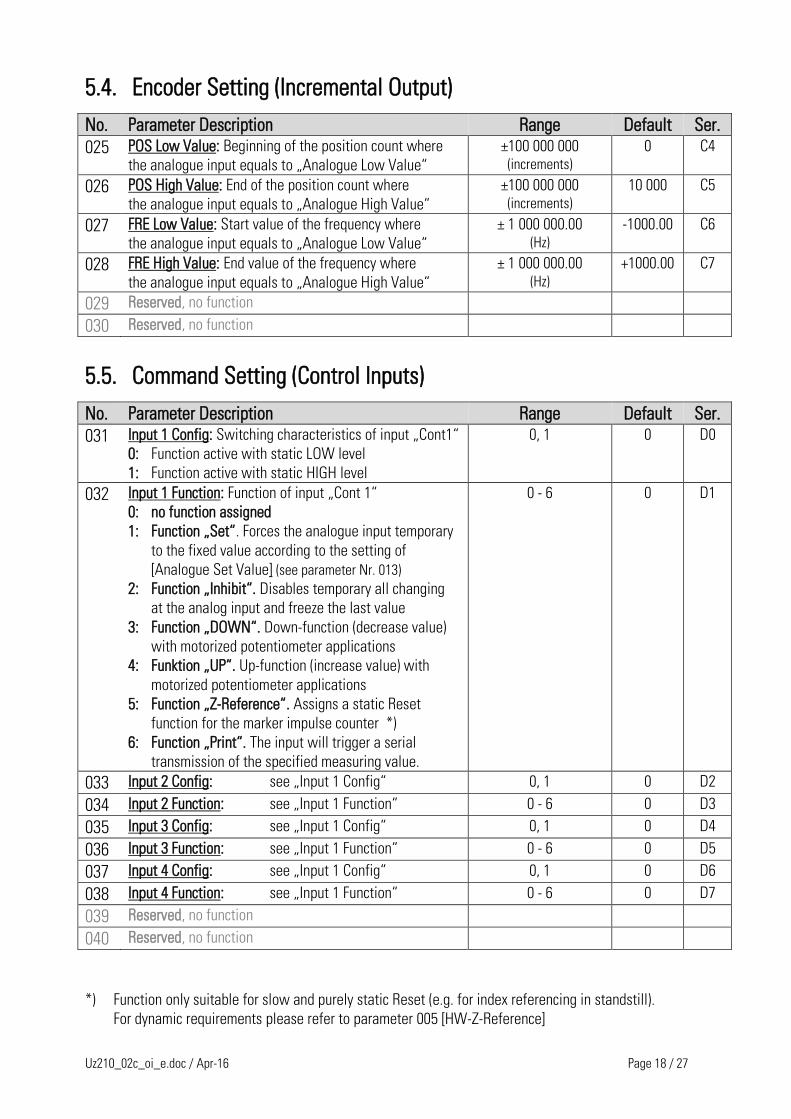
5.4. Encoder Setting (Incremental Output)
No. Parameter Description Range Default Ser.
025 POS Low Value: Beginning of the position count where
the analogue input equals to „Analogue Low Value“
±100 000 000 (increments)
0 C4
026 POS High Value: End of the position count where
the analogue input equals to „Analogue High Value“
±100 000 000 (increments)
10 000 C5
027 FRE Low Value: Start value of the frequency where
the analogue input equals to „Analogue Low Value“
± 1 000 000.00 (Hz)
-1000.00 C6
028 FRE High Value: End value of the frequency where
the analogue input equals to „Analogue High Value“
± 1 000 000.00 (Hz)
+1000.00 C7
029 Reserved, no function
030 Reserved, no function
5.5. Command Setting (Control Inputs)
No. Parameter Description Range Default Ser.
031 Input 1 Config: Switching characteristics of input „Cont1“
0: Function active with static LOW level
1: Function active with static HIGH level
0, 1 0 D0
032 Input 1 Function: Function of input „Cont 1“
0: no function assigned
1: Function „Set“. Forces the analogue input temporary
to the fixed value according to the setting of
[Analogue Set Value] (see parameter Nr. 013)
2: Function „Inhibit“. Disables temporary all changing
at the analog input and freeze the last value
3: Function „DOWN“. Down-function (decrease value)
with motorized potentiometer applications
4: Funktion „UP“. Up-function (increase value) with
motorized potentiometer applications
5: Function „Z-Reference“. Assigns a static Reset
function for the marker impulse counter *)
6: Function „Print“. The input will trigger a serial
transmission of the specified measuring value.
0 - 6 0 D1
033 Input 2 Config: see „Input 1 Config“ 0, 1 0 D2
034 Input 2 Function: see „Input 1 Function“ 0 - 6 0 D3
035 Input 3 Config: see „Input 1 Config“ 0, 1 0 D4
036 Input 3 Function: see „Input 1 Function“ 0 - 6 0 D5
037 Input 4 Config: see „Input 1 Config“ 0, 1 0 D6
038 Input 4 Function: see „Input 1 Function“ 0 - 6 0 D7
039 Reserved, no function
040 Reserved, no function
*) Function only suitable for slow and purely static Reset (e.g. for index referencing in standstill).
For dynamic requirements please refer to parameter 005 [HW-Z-Reference]
Uz210_02c_oi_e.doc / Apr-16 Page 19 / 27
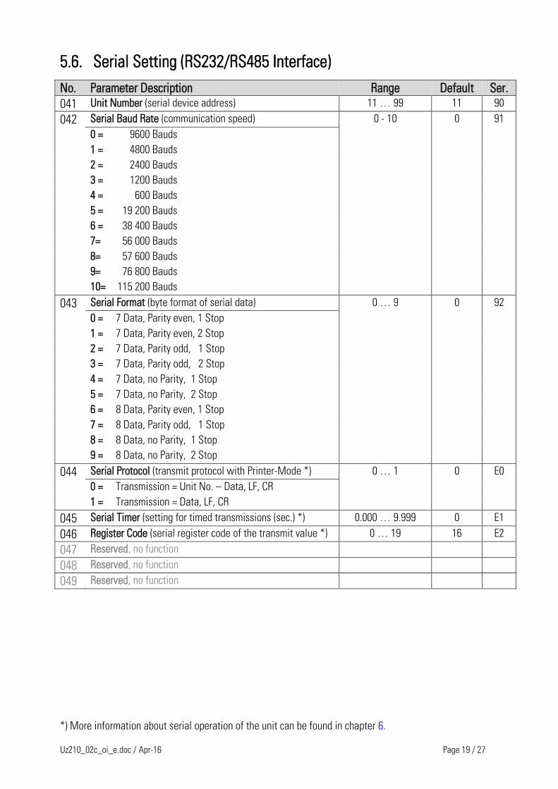
5.6. Serial Setting (RS232/RS485 Interface)
No. Parameter Description Range Default Ser.
041 Unit Number (serial device address) 11 … 99 11 90
042 Serial Baud Rate (communication speed) 0 - 10 0 91
0 = 9600 Bauds
1 = 4800 Bauds
2 = 2400 Bauds
3 = 1200 Bauds
4 = 600 Bauds
5 = 19 200 Bauds
6 = 38 400 Bauds
7= 56 000 Bauds
8= 57 600 Bauds
9= 76 800 Bauds
10= 115 200 Bauds
043 Serial Format (byte format of serial data) 0 … 9 0 92
0 = 7 Data, Parity even, 1 Stop
1 = 7 Data, Parity even, 2 Stop
2 = 7 Data, Parity odd, 1 Stop
3 = 7 Data, Parity odd, 2 Stop
4 = 7 Data, no Parity, 1 Stop
5 = 7 Data, no Parity, 2 Stop
6 = 8 Data, Parity even, 1 Stop
7 = 8 Data, Parity odd, 1 Stop
8 = 8 Data, no Parity, 1 Stop
9 = 8 Data, no Parity, 2 Stop
044 Serial Protocol (transmit protocol with Printer-Mode *) 0 … 1 0 E0
0 = Transmission = Unit No. – Data, LF, CR
1 = Transmission = Data, LF, CR
045 Serial Timer (setting for timed transmissions (sec.) *) 0.000 … 9.999 0 E1
046 Register Code (serial register code of the transmit value *) 0 … 19 16 E2
047 Reserved, no function
048 Reserved, no function
049 Reserved, no function
*) More information about serial operation of the unit can be found in chapter 6.
Uz210_02c_oi_e.doc / Apr-16 Page 20 / 27
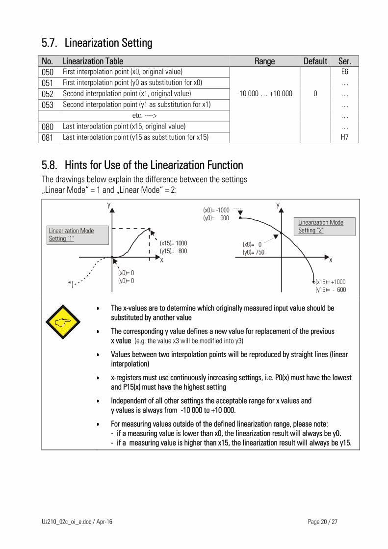
5.7. Linearization Setting
No. Linearization Table Range Default Ser.
050 First interpolation point (x0, original value) E6
051 First interpolation point (y0 as substitution for x0) …
052 Second interpolation point (x1, original value) -10 000 … +10 000 0 …
053 Second interpolation point (y1 as substitution for x1) …
etc. ----> …
080 Last interpolation point (x15, original value) …
081 Last interpolation point (y15 as substitution for x15) H7
5.8. Hints for Use of the Linearization Function The drawings below explain the difference between the settings
„Linear Mode“ = 1 and „Linear Mode“ = 2:
x
y
(x0)= 0
(y0)= 0
Linearization Mode
Setting "1"
x
y
Linearization Mode
Setting "2"
(x0)= -1000
(y0)= 900
(x8)= 0
(y8)= 750
(x15)= +1000
(y15)= - 600*)
(x15)= 1000
(y15)= 800
The x-values are to determine which originally measured input value should be
substituted by another value
The corresponding y value defines a new value for replacement of the previous
x value (e.g. the value x3 will be modified into y3)
Values between two interpolation points will be reproduced by straight lines (linear
interpolation)
x-registers must use continuously increasing settings, i.e. P0(x) must have the lowest
and P15(x) must have the highest setting
Independent of all other settings the acceptable range for x values and
y values is always from -10 000 to +10 000.
For measuring values outside of the defined linearization range, please note:
- if a measuring value is lower than x0, the linearization result will always be y0.
- if a measuring value is higher than x15, the linearization result will always be y15.
Uz210_02c_oi_e.doc / Apr-16 Page 21 / 27
6. Hints for Serial Communication Serial communication with the UZ210 converter is intended to be used for
Setup and programming of the unit by PC with operator software OS32 (see chapter 5)
Automatic and cyclic transmission of converter data to a PC or PLC or data logger
Free communication with PC or PLC using the communication protocol
This chapter describes the most essential communication functions only. For more detailed and
general information please refer to the special document “SERPRO”.
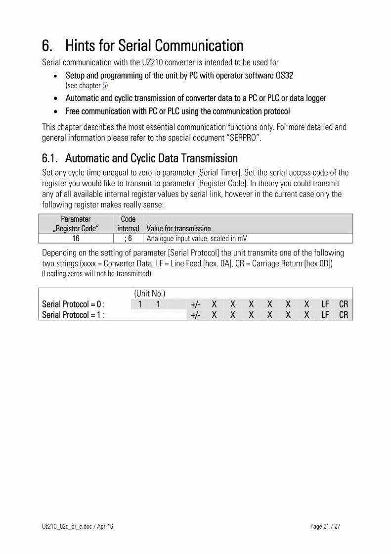
6.1. Automatic and Cyclic Data Transmission Set any cycle time unequal to zero to parameter [Serial Timer]. Set the serial access code of the
register you would like to transmit to parameter [Register Code]. In theory you could transmit
any of all available internal register values by serial link, however in the current case only the
following register makes really sense:
Parameter
„Register Code“
Code
internal
Value for transmission
16 ; 6 Analogue input value, scaled in mV
Depending on the setting of parameter [Serial Protocol] the unit transmits one of the following
two strings (xxxx = Converter Data, LF = Line Feed [hex. 0A], CR = Carriage Return [hex 0D]) (Leading zeros will not be transmitted)
(Unit No.)
Serial Protocol = 0 : 1 1 +/- X X X X X X LF CR
Serial Protocol = 1 : +/- X X X X X X LF CR
Uz210_02c_oi_e.doc / Apr-16 Page 22 / 27
6.2. Communication Protocol When communicating with the unit via protocol, you have full read/write access to all internal
parameters, states and actual values. The protocol uses the DRIVECOM standard according to
DIN ISO 1745. The serial access codes of all parameters can be found in the parameter
description (see chapter 5).
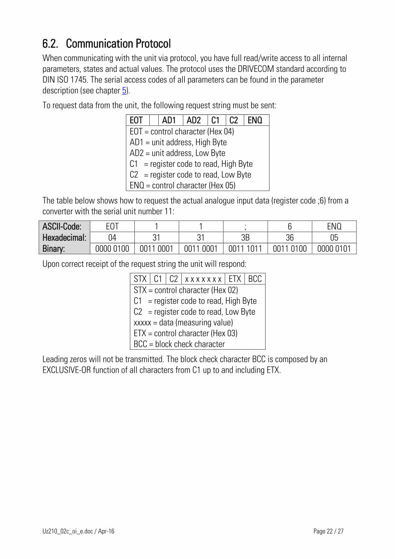
To request data from the unit, the following request string must be sent:
EOT AD1 AD2 C1 C2 ENQ
EOT = control character (Hex 04)
AD1 = unit address, High Byte
AD2 = unit address, Low Byte
C1 = register code to read, High Byte
C2 = register code to read, Low Byte
ENQ = control character (Hex 05)
The table below shows how to request the actual analogue input data (register code ;6) from a
converter with the serial unit number 11:
ASCII-Code: EOT 1 1 ; 6 ENQ
Hexadecimal: 04 31 31 3B 36 05
Binary: 0000 0100 0011 0001 0011 0001 0011 1011 0011 0100 0000 0101
Upon correct receipt of the request string the unit will respond:
STX C1 C2 x x x x x x x ETX BCC
STX = control character (Hex 02)
C1 = register code to read, High Byte
C2 = register code to read, Low Byte
xxxxx = data (measuring value)
ETX = control character (Hex 03)
BCC = block check character
Leading zeros will not be transmitted. The block check character BCC is composed by an
EXCLUSIVE-OR function of all characters from C1 up to and including ETX.
Uz210_02c_oi_e.doc / Apr-16 Page 23 / 27
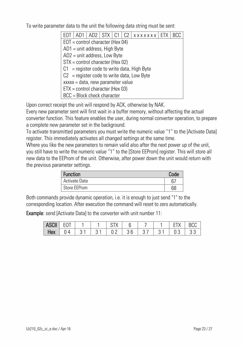
To write parameter data to the unit the following data string must be sent:
EOT AD1 AD2 STX C1 C2 x x x x x x x ETX BCC
EOT = control character (Hex 04)
AD1 = unit address, High Byte
AD2 = unit address, Low Byte
STX = control character (Hex 02)
C1 = register code to write data, High Byte
C2 = register code to write data, Low Byte
xxxxx = data, new parameter value
ETX = control character (Hex 03)
BCC = Block check character
Upon correct receipt the unit will respond by ACK, otherwise by NAK.
Every new parameter sent will first wait in a buffer memory, without affecting the actual
converter function. This feature enables the user, during normal converter operation, to prepare
a complete new parameter set in the background.
To activate transmitted parameters you must write the numeric value “1” to the [Activate Data]
register. This immediately activates all changed settings at the same time.
Where you like the new parameters to remain valid also after the next power up of the unit,
you still have to write the numeric value “1” to the [Store EEProm] register. This will store all
new data to the EEProm of the unit. Otherwise, after power down the unit would return with
the previous parameter settings.
Function Code Activate Data 67 Store EEProm 68
Both commands provide dynamic operation, i.e. it is enough to just send "1" to the
corresponding location. After execution the command will reset to zero automatically.
Example: send [Activate Data] to the converter with unit number 11:
ASCII EOT 1 1 STX 6 7 1 ETX BCC
Hex 0 4 3 1 3 1 0 2 3 6 3 7 3 1 0 3 3 3

Uz210_02c_oi_e.doc / Apr-16 Page 24 / 27
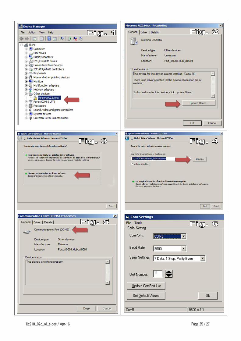
7. Hints for Operation of the USB Port Prior to using the USB port it is mandatory to store the driver file „motrona_vcom.inf“ in a user-
defined directory of the PC (any directory according to your own choice will be fine). The driver
file is available for download from the SUPPORT section of the motrona website
www.motrona.com.
After the very first USB connection between PC and converter the Plug-and-Play-Function of the
PC will first try to find a suitable driver via Internet. You are free to either abort the internet
search or to just wait for the message “no suitable driver found”. After this, please follow the
subsequent steps to install the driver manually:
Click to Start, select Control Panel and from there choose Device Manager. Among other devices
the device manager will now indicate one unit named Motrona_UZ210xx (Fig. 1).
Double-click to Motrona_UZ210_xx and choose Update Driver (Fig. 2)
Now select Browse my computer for driver software. Then select exactly the folder to where
before you have saved the motrona_vcom.inf driver file. In our example the driver has been stored
on drive D in the folder MOTRONA\Motrona_Software\driver (Fig. 3 and 4).
After assignment of the driver, the USB Port will be configured as a communication interface and
the number of the Virtual Com Port attached by the system is shown on the screen (in our example
this is COM 5, see Fig. 5).
Now we are ready to start the OS32 Operator software. Please select first the „Coms“ menu of the
OS32 software to set the communication parameters correspondingly (Fig. 6).
USB communication between converter and PC has now successfully been installed and the
OS32 Operator Software is ready to work.
When two OS32 Operator Software programs are running at the same time (one via USB
and the other via serial), the indicator box Dual OS of the OUTPUTS column will be ON
(this indication responds with a short delay).
In the Inputs field both columns, RS and BUS will now be active.
Column RS indicates all commands released by the PC actually in use, and column BUS
indicates all commands released by the other (remote) OS32 Software. At any time column
PI/O indicates the logical state of the hardware command inputs of the unit.
It is possible to disable parameter settings and changes coming from the other (remote)
OS32 software. This can be achieved by setting the command Overwrite Buffer to ON.
When switched ON, the commands „Activate Data“ and „Store EEProm“ of the second
communication channel will be suppressed. This is to ensure that parameter settings can
happen only by the PC currently used, and no undesirable modifications will get in from the
other (remote) communication port.
Whenever two PC’s run the OS32 software simultaneously, it is important to never enter
the Test menu from any of the two sides!
Uz210_02c_oi_e.doc / Apr-16 Page 25 / 27
Uz210_02c_oi_e.doc / Apr-16 Page 26 / 27
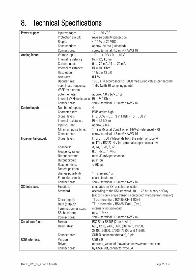
8. Technical Specifications
Power supply: Input voltage:
Protection circuit:
Ripple:
Consumption:
Connections:
12 … 30 VDC
reverse polarity protection
≤ 10 % at 24 VDC
approx. 50 mA (unloaded)
screw terminal, 1.5 mm² / AWG 16
Analog input: Voltage input:
Internal resistance:
Current input:
Internal resistance:
Resolution:
Accuracy:
Update-time:
max. Input frequency:
VREF for external
potentiometer:
Internal VREF resistance:
Connections:
-10 … +10 V / 0 … 10 V
Ri ≈ 120 kOhm
0 … 20 mA / 4 … 20 mA
Ri ≈ 100 Ohm
14 bit (± 13 bit)
0.1 %
100 μs (in accordance to 10000 measuring values per second)
1 kHz (with 10 sampling points)
approx. 4.8 V (+/- 0.1%)
Ri ≈ 240 Ohm
screw terminal, 1.5 mm² / AWG 16
Control inputs: Number of inputs:
Characteristic:
Signal levels:
Internal resistance:
Input current:
Minimum pulse time:
Connections:
4
PNP, active high
HTL: LOW = 0 … 3 V, HIGH = 10 … 30 V
Ri ≈ 1.5 kOhm
approx. 2 mA
1 msec (5 μs at Cont.1 when [HW-Z-Reference] ≠ 0)
screw terminal, 1.5 mm² / AWG 16
Incremental output: Signal levels:
Channels:
Frequency range:
Output current:
Output circuit:
Reaction time:
Fastest position
change possibility:
Protection circuit:
Connections:
HTL: 5 … 30 V (depends from the external supply)
or TTL / RS422: 4 V (no external supply necessary)
A, /A, B, /B, Z, /Z
0.01 Hz … 1 MHz
max. 30 mA (per channel)
push-pull
< 260 µs
1 increment / μs
short circuit proof
screw terminal, 1.5 mm² / AWG 16
SSI interface: Function:
Standard:
Clock (input):
Data (output):
Termination resistors:
SSI baud rate:
Connections:
simulates an SSI absolute encoder
according to the SSI standard, 10 … 25 bit, binary or Gray
(supports only single transmission but not multiple-transmission)
TTL-differential / RS485 [Clk+], [Clk-]
TTL-differential / RS485 [Dat+], [Dat-]
internally not provided
max. 1 MHz
screw terminal, 1.5 mm² / AWG 16
Serial interface: Format:
Baud rates:
Connections:
RS232 or RS485 (2- or 4-wire)
600, 1200, 2400, 9600 (Default), 19200,
38400, 56000, 57600, 76800 and 115200
SUB-D connector (female), 9-pin
USB interface: Version:
Driver:
Connections:
USB 2.0
motrona_vcom.inf (download on www.motrona.com)
by USB-Port, connector type „A
Uz210_02c_oi_e.doc / Apr-16 Page 27 / 27
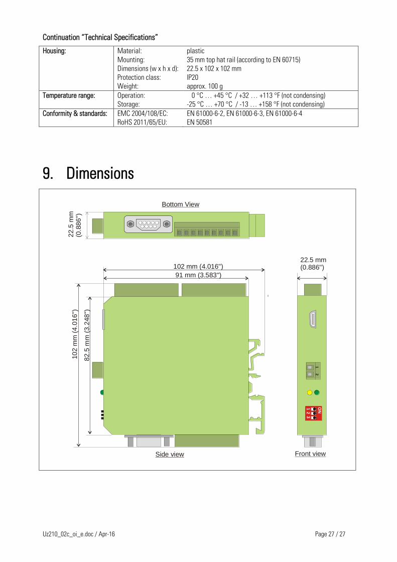
Continuation “Technical Specifications”
Housing: Material:
Mounting:
Dimensions (w x h x d):
Protection class:
Weight:
plastic
35 mm top hat rail (according to EN 60715)
22.5 x 102 x 102 mm
IP20
approx. 100 g
Temperature range: Operation:
Storage:
0 °C … +45 °C / +32 … +113 °F (not condensing)
-25 °C … +70 °C / -13 … +158 °F (not condensing)
Conformity & standards: EMC 2004/108/EC:
RoHS 2011/65/EU:
EN 61000-6-2, EN 61000-6-3, EN 61000-6-4
EN 50581
9. Dimensions
102 mm (4.016'')
91 mm (3.583'')
82.5
mm
(3.2
48
'')
10
2 m
m (
4.0
16'')
12
3
ON
Side view
Bottom View
Front view
22.5
mm
(0.8
86'')
12
22.5 mm(0.886'')