Embed Size (px)
Citation preview

Operating Manual
AMAZONE
FT 1001
Front tank for mounted UF field sprayer
MG3058 BAG0065.8 02.21 Printed in Germany
Please read this operating manual before commissioning.
Keep it in a safe place for future use.
en

2 FT BAG0065.8 02.21
Reading the instruction Manual and following it should seem to be in-convenient and superfluous as it is not enough to hear from others and to realize that a machine is good, to buy it and to believe that now everything should work by itself. The person in question would not only harm himself but also make the mistake of blaming the machine for pos-sible failures instead of himself. In order to ensure success one should enter the mind of a thing, make himself familiar with every part of the ma-chine and get acquainted with how it's handled. Only in this way could you be satisfied both with the machine and with yourself. This goal is the purpose of this instruction manual.
Leipzig-Plagwitz 1872.

Identification data
FT BAG0065.8 02.21 3
Manufacturer's address
AMAZONEN-WERKE
H. DREYER SE & Co. KG
Postfach 51
D-49202
Phone:
E-mail:
Hasbergen, Germany
+ 49 5405-501-0
Spare part orders
Spare parts lists are freely accessible in the spare parts portal at www.amazone.de.
Please send orders to your AMAZONE dealer.
Formalities of the operating manual
Document number: MG3058
Compilation date: 02.21
Copyright AMAZONEN-WERKE H. DREYER SE & Co. KG, 2021
All rights reserved.
Reprinting, even of extracts, is only possible with the approval of AMAZONEN-WERKE H. DREYER SE & Co. KG.

Table of Contents
4 FT BAG0065.8 02.21
1 User Information .......................................................................................... 6 1.1 Purpose of the document ........................................................................................................ 6 1.2 Locations in the operating manual .......................................................................................... 6 1.3 Diagrams ................................................................................................................................. 6
2 General safety instructions ........................................................................ 7 2.1 Obligations and liability............................................................................................................ 7 2.2 Representation of safety symbols ........................................................................................... 9 2.3 Organisational measures ...................................................................................................... 10 2.4 Safety and protection equipment .......................................................................................... 10 2.5 Informal safety measures ...................................................................................................... 10 2.6 User training .......................................................................................................................... 11 2.7 Safety measures in normal operation ................................................................................... 12 2.8 Danger from residual energy ................................................................................................. 12 2.9 Maintenance and repair work, fault elimination ..................................................................... 12 2.10 Design changes ..................................................................................................................... 12 2.10.1 Spare and wear parts and aids ............................................................................................. 13 2.11 Cleaning and disposal ........................................................................................................... 13 2.12 User workstation .................................................................................................................... 13 2.13 Warning symbols and other signs on the machine ............................................................... 14 2.13.1 Positions of warning symbols and other labels ..................................................................... 15 2.14 Dangers if the safety information is not observed ................................................................. 17 2.15 Safety-conscious working ..................................................................................................... 17 2.16 Safety information for users .................................................................................................. 18 2.16.1 General safety and accident prevention information ............................................................. 18 2.16.2 Field sprayer operation.......................................................................................................... 21 2.16.3 Cleaning, maintenance and repairs ...................................................................................... 22
3 Loading and unloading ............................................................................. 23
4 Product description .................................................................................. 24 4.1 Overview ............................................................................................................................... 24 4.2 Overview of Flow Control ...................................................................................................... 25 4.3 Technical data ....................................................................................................................... 26 4.3.1 Payload ................................................................................................................................. 26 4.4 Intended use .......................................................................................................................... 27 4.5 Danger areas and danger points ........................................................................................... 28 4.6 Machine rating plate .............................................................................................................. 29 4.7 Three-point attachment frame ............................................................................................... 29 4.8 Transport device (removable) ............................................................................................... 30 4.9 Transportation equipment ..................................................................................................... 31 4.10 Non-certified camera system ................................................................................................ 31
5 UF01 and FT 1001 without Flow Control ........................................... 32 5.1 Filling the front tank via the UF01 field sprayer .................................................................. 32 5.2 Filling the UF01 spray liquid tank via the front tank ............................................................ 34
6 UF01 and FT1001 with Flow Control (optional) ................................. 35 6.1 Flow Control liquid circuit ...................................................................................................... 35 6.2 Additional tank for flushing water .......................................................................................... 36 6.3 Connect field sprayer with Flow Control and front tank ........................................................ 37 6.4 Automatic mode .................................................................................................................... 38 6.5 Manual mode ......................................................................................................................... 39 6.6 Front tank submenu .............................................................................................................. 40 6.7 Filling ..................................................................................................................................... 41
Table of Contents
FT BAG0065.8 02.21 5
6.8 Internal cleaning ..................................................................................................................... 41 6.9 Failure of a level sensor ......................................................................................................... 41
7 UF02 and FT 1001 without FlowControl .................................... 42 7.1 Filling the front tank via the UF field sprayer ........................................................................ 42 7.2 Filling the UF spray liquid tank via the front tank .................................................................. 44
8 UF02 and FT 1001 with Flow Control (optional) ............................... 46 8.1 Flow Control liquid circuit ....................................................................................................... 46 8.2 Connect field sprayer with Flow Control and front tank ......................................................... 47 8.3 FlowControl and ISOBUS ...................................................................................................... 48 8.4 Filling ...................................................................................................................................... 49 8.5 Internal cleaning ..................................................................................................................... 49 8.6 Failure of a fill level sensor .................................................................................................... 49 8.7 Pump maintenance ................................................................................................................ 50 8.7.1 Adjust the air pressure in the pressure reservoir ................................................................... 50 8.7.2 Replacing the pressure reservoir diaphragm ......................................................................... 51
9 Commissioning .......................................................................................... 52 9.1 Fastening the front tank supply lines on the tractor ............................................................... 53
10 Coupling and uncoupling the machine .................................................... 54 10.1 Coupling the machine ............................................................................................................ 54 10.2 Uncoupling the machine ........................................................................................................ 56
11 Transportation ........................................................................................... 57
User Information
6 FT BAG0065.8 02.21
1 User Information
The User Information section provides information on use of the oper-ating manual.
1.1 Purpose of the document
This operating manual
• describes the operation and maintenance of the machine.
• provides important information on safe and efficient handling of the machine.
• is a component part of the machine and should always be kept with the machine or the towing vehicle.
• Keep it in a safe place for future use.
1.2 Locations in the operating manual
All the directions specified in the operating manual are always seen in the direction of travel.
1.3 Diagrams
Instructions and responses
Activities to be carried out by the user are given as numbered instruc-tions. Always keep to the order of the instructions. The response to an instruction is given by an arrow.
Example: 1. Instruction 1 → Machine response to instruction 1 2. Instruction 2
Lists
Lists without an essential order are shown as a list with bullets.
Example: • Point 1 • Point 2
Item numbers in diagrams
Numbers in round brackets refer to the item numbers in the diagrams. The first number refers to the diagram and the second number to the item.
Example: (Fig. 3/6) • Figure 3 • Item 6
General safety instructions
FT BAG0065.8 02.21 7
2 General safety instructions
This section contains important information on safe operation of the machine.
2.1 Obligations and liability
Comply with the instructions in the operating manual
Knowledge of the basic safety information and safety regulations is a basic requirement for safe handling and fault-free machine operation.
Obligations of the operator
The operator is obliged only to let those people work with/on the ma-chine who
• are aware of the basic workplace safety information and accident prevention regulations.
• have been instructed in working with/on the machine.
• have read and understood this operating manual.
The operator is obliged
• to keep all the warning symbols on the machine in a legible state.
• to replace damaged warning symbols.
• If you still have queries, please contact the manufacturer.
Obligations of the user
Before starting work, anyone charged with working with/on the ma-chine is obliged
• to comply with the basic workplace safety instructions and acci-dent prevention regulations.
• to read and follow the "General safety information" section of this operating manual.
• to read the section "Warning symbols and other labels on the machine" (page 14) of this operating manual and to follow the safety instructions represented by the warning symbols when operating the machine.
• to get to know the machine. • to read the sections of this operating manual that are important
for carrying out their work.
If the user discovers that a function is not working properly, then they must eliminate this fault immediately. If this is not the task of the user or if the user does not possess the appropriate technical knowledge, then they should report this fault to their superior (operator).
General safety instructions
8 FT BAG0065.8 02.21
Risks in handling the machine
The machine has been constructed to the state-of-the art and the recognised rules of safety. However, operating the machine may cause risks and restrictions to
• the health and safety of the user or third parties,
• the machine,
• other property.
Only use the machine
• for the purpose for which it was intended.
• in a perfect state of repair.
Eliminate any faults immediately which could impair safety.
Guarantee and liability
Our "General conditions of sales and delivery" are always applicable. These shall be available to the operator, at the latest on conclusion of the contract. Guarantee and liability claims for damage to people or property will be excluded if they can be traced back to one or more of the following causes:
• Improper use of the machine.
• Improper installation, commissioning, operation and mainte-nance of the machine.
• Operation of the machine with defective safety equipment or improperly attached or non-functioning safety equipment.
• Non-compliance with the instructions in the operating manual regarding commissioning, operation and maintenance.
• Unauthorised design changes to the machine.
• Insufficient monitoring of machine parts which are subject to wear.
• Improperly executed repairs.
• Disasters through the impact of foreign bodies and Acts of God.
General safety instructions
FT BAG0065.8 02.21 9
2.2 Representation of safety symbols
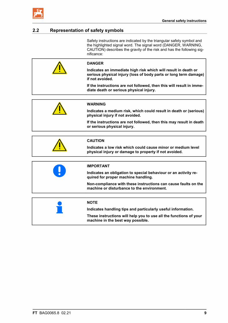
Safety instructions are indicated by the triangular safety symbol and the highlighted signal word. The signal word (DANGER, WARNING, CAUTION) describes the gravity of the risk and has the following sig-nificance:
DANGER Indicates an immediate high risk which will result in death or serious physical injury (loss of body parts or long term damage) if not avoided. If the instructions are not followed, then this will result in imme-diate death or serious physical injury.
WARNING
Indicates a medium risk, which could result in death or (serious) physical injury if not avoided. If the instructions are not followed, then this may result in death or serious physical injury.
CAUTION Indicates a low risk which could cause minor or medium level physical injury or damage to property if not avoided.
IMPORTANT Indicates an obligation to special behaviour or an activity re-quired for proper machine handling. Non-compliance with these instructions can cause faults on the machine or disturbance to the environment.
NOTE Indicates handling tips and particularly useful information. These instructions will help you to use all the functions of your machine in the best way possible.
General safety instructions
10 FT BAG0065.8 02.21
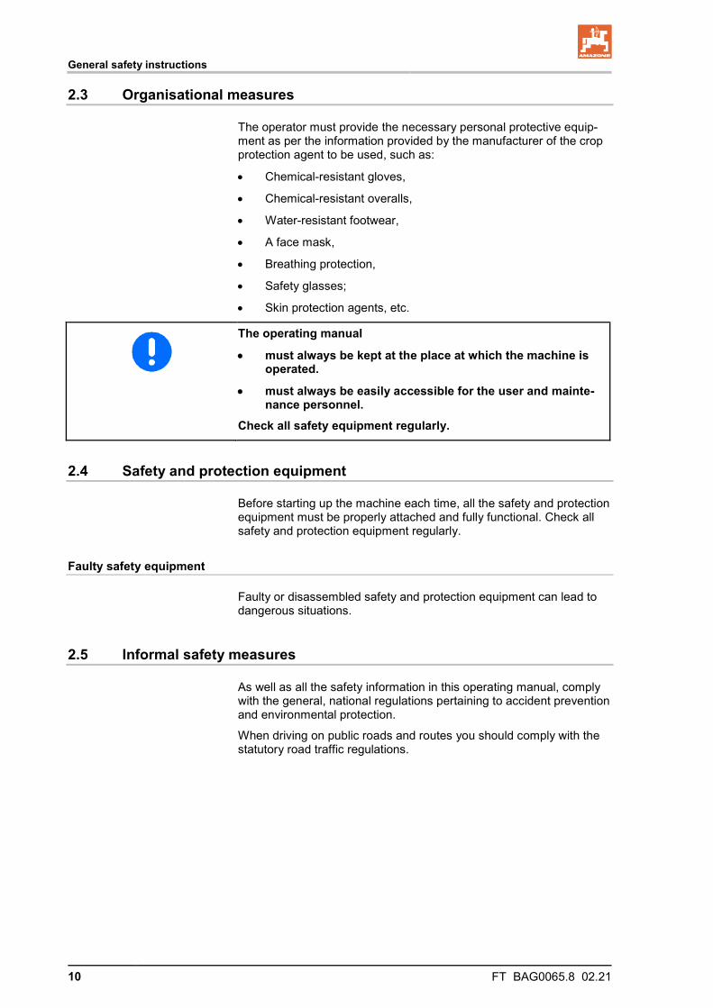
2.3 Organisational measures
The operator must provide the necessary personal protective equip-ment as per the information provided by the manufacturer of the crop protection agent to be used, such as:
• Chemical-resistant gloves,
• Chemical-resistant overalls,
• Water-resistant footwear,
• A face mask,
• Breathing protection,
• Safety glasses;
• Skin protection agents, etc.
The operating manual
• must always be kept at the place at which the machine is operated.
• must always be easily accessible for the user and mainte-nance personnel.
Check all safety equipment regularly.
2.4 Safety and protection equipment
Before starting up the machine each time, all the safety and protection equipment must be properly attached and fully functional. Check all safety and protection equipment regularly.
Faulty safety equipment
Faulty or disassembled safety and protection equipment can lead to dangerous situations.
2.5 Informal safety measures
As well as all the safety information in this operating manual, comply with the general, national regulations pertaining to accident prevention and environmental protection.
When driving on public roads and routes you should comply with the statutory road traffic regulations.
General safety instructions
FT BAG0065.8 02.21 11
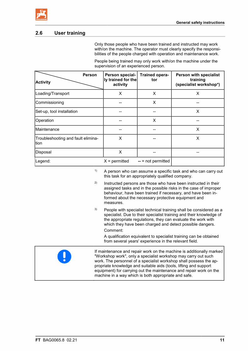
2.6 User training
Only those people who have been trained and instructed may work with/on the machine. The operator must clearly specify the responsi-bilities of the people charged with operation and maintenance work.
People being trained may only work with/on the machine under the supervision of an experienced person.
Person Activity
Person special-ly trained for the
activity
Trained opera-tor
Person with specialist training
(specialist workshop*)
Loading/Transport X X X
Commissioning -- X --
Set-up, tool installation -- -- X
Operation -- X --
Maintenance -- -- X
Troubleshooting and fault elimina-tion
X -- X
Disposal X -- --
Legend: X = permitted -- = not permitted
1) A person who can assume a specific task and who can carry out this task for an appropriately qualified company.
2) Instructed persons are those who have been instructed in their assigned tasks and in the possible risks in the case of improper behaviour, have been trained if necessary, and have been in-formed about the necessary protective equipment and measures.
3) People with specialist technical training shall be considered as a specialist. Due to their specialist training and their knowledge of the appropriate regulations, they can evaluate the work with which they have been charged and detect possible dangers.
Comment: A qualification equivalent to specialist training can be obtained
from several years' experience in the relevant field.
If maintenance and repair work on the machine is additionally marked "Workshop work", only a specialist workshop may carry out such work. The personnel of a specialist workshop shall possess the ap-propriate knowledge and suitable aids (tools, lifting and support equipment) for carrying out the maintenance and repair work on the machine in a way which is both appropriate and safe.
General safety instructions
12 FT BAG0065.8 02.21
2.7 Safety measures in normal operation
Only operate the machine if all the safety and protection equipment is fully functional.
Check the machine at least once a day for visible damage and check the function of the safety and protection equipment.
2.8 Danger from residual energy
Note that there may be residual mechanical, hydraulic, pneumatic and electrical/electronic energy on the machine.
Use appropriate measures to inform the operating personnel. You can find detailed information in the relevant sections of this operating manual.
2.9 Maintenance and repair work, fault elimination
Carry out prescribed setting, maintenance and inspection work in good time.
Secure all media such as compressed air and the hydraulic system against unintentional start-up.
Carefully fix and secure larger assemblies to lifting gear when carry-ing out replacement work.
Check all the screw connections for firm seating. On completion of the maintenance work, check the function of the safety devices.
2.10 Design changes
You may make no changes, expansions or modifications to the ma-chine without the authorisation of AMAZONEN-WERKE. This also applies when welding support parts.
Any expansion or modification work shall require the written approval of AMAZONEN-WERKE. Only use modification and accessory parts approved by AMAZONEN-WERKE so that the type approval, for ex-ample, remains valid in accordance with national and international regulations.
Vehicles with an official type approval or with equipment connected to a vehicle with a valid type approval or approval for road transport according to the German road traffic regulations must be in the state specified by the approval.
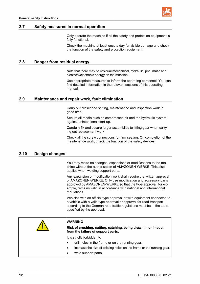
WARNING Risk of crushing, cutting, catching, being drawn in or impact from the failure of support parts. It is strictly forbidden to • drill holes in the frame or on the running gear. • increase the size of existing holes on the frame or the running gear. • weld support parts.
General safety instructions
FT BAG0065.8 02.21 13
2.10.1 Spare and wear parts and aids
Immediately replace any machine parts which are not in a perfect state.
Only use genuine AMAZONE spare and wear parts or those approved by AMAZONEN-WERKE so that the type approval remains valid ac-cording to the national and international regulations. The use of spare and wear parts from third parties does not guarantee that they have been constructed in a way as to meet the requirements placed on them.
AMAZONEN-WERKE shall accept no liability for damage caused by the use of non-approved spare and wear parts or aids.
2.11 Cleaning and disposal
Handle and dispose of any materials used carefully, in particular
• when carrying out work on lubrication systems and equipment and
• when cleaning using solvents.
2.12 User workstation
The machine may only be operated by one person sitting in the driv-er's seat of the tractor.
General safety instructions
14 FT BAG0065.8 02.21
2.13 Warning symbols and other signs on the machine
Always keep all the warning symbols on the machine clean and in a legible state. Replace illegible warning symbols. You can obtain the warning symbols from your dealer using the order number (e.g. MD 075).
Warning symbols - structure
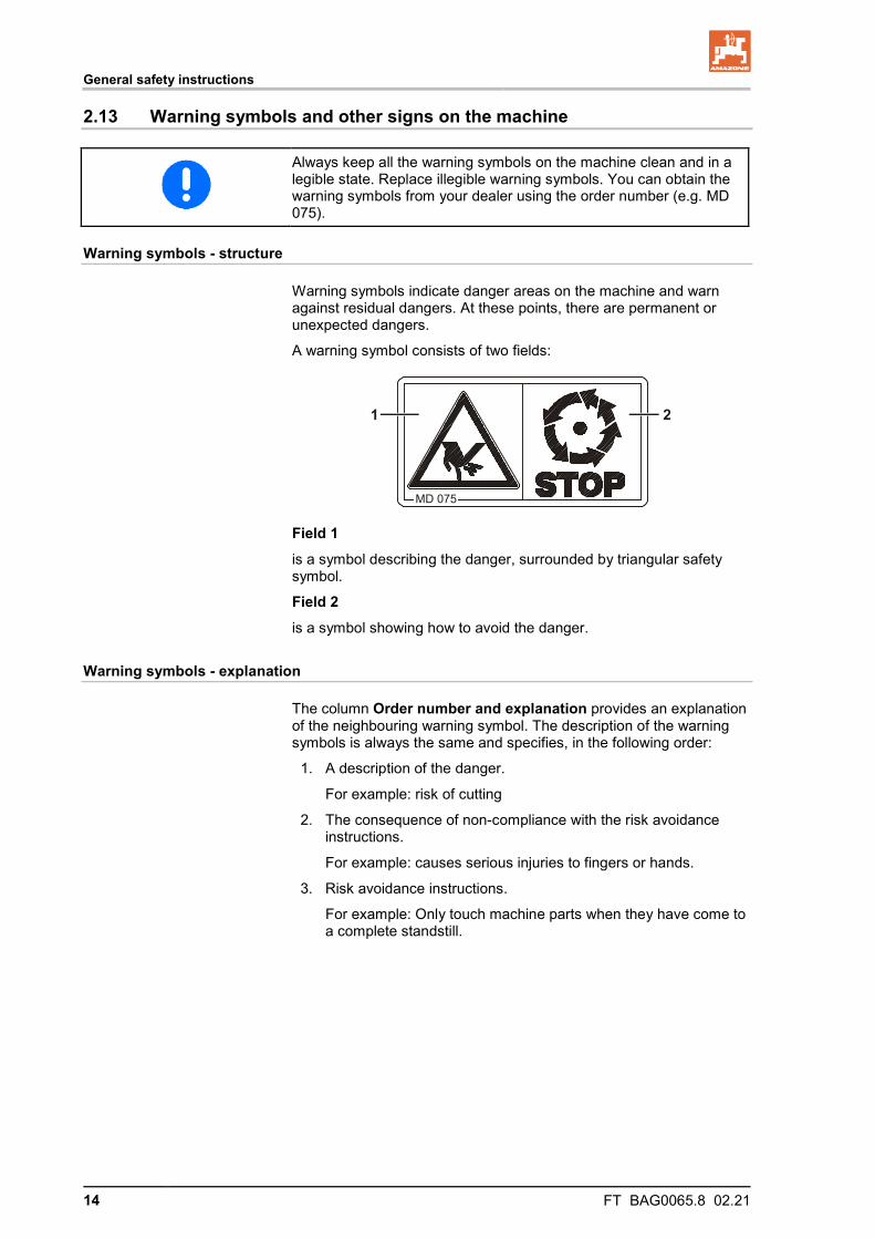
Warning symbols indicate danger areas on the machine and warn against residual dangers. At these points, there are permanent or unexpected dangers.
A warning symbol consists of two fields:
Field 1
is a symbol describing the danger, surrounded by triangular safety symbol.
Field 2 is a symbol showing how to avoid the danger.
Warning symbols - explanation
The column Order number and explanation provides an explanation of the neighbouring warning symbol. The description of the warning symbols is always the same and specifies, in the following order:
1. A description of the danger.
For example: risk of cutting
2. The consequence of non-compliance with the risk avoidance instructions.
For example: causes serious injuries to fingers or hands.
3. Risk avoidance instructions.
For example: Only touch machine parts when they have come to a complete standstill.
General safety instructions
FT BAG0065.8 02.21 15
2.13.1 Positions of warning symbols and other labels
Warning symbols
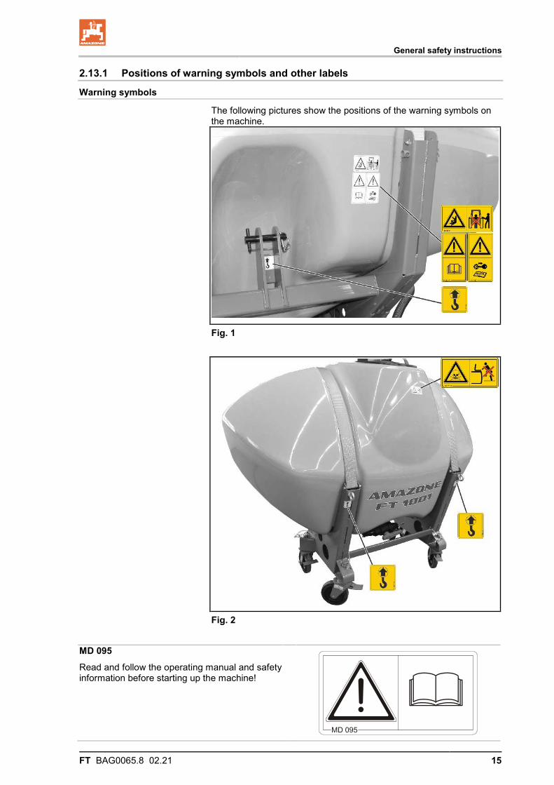
The following pictures show the positions of the warning symbols on the machine.
Fig. 1
Fig. 2 MD 095 Read and follow the operating manual and safety information before starting up the machine!
General safety instructions
16 FT BAG0065.8 02.21
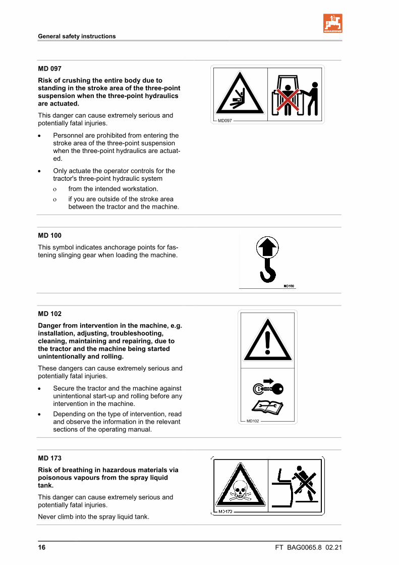
MD 097 Risk of crushing the entire body due to standing in the stroke area of the three-point suspension when the three-point hydraulics are actuated. This danger can cause extremely serious and potentially fatal injuries.
• Personnel are prohibited from entering the stroke area of the three-point suspension when the three-point hydraulics are actuat-ed.
• Only actuate the operator controls for the tractor's three-point hydraulic system ο from the intended workstation. ο if you are outside of the stroke area
between the tractor and the machine.
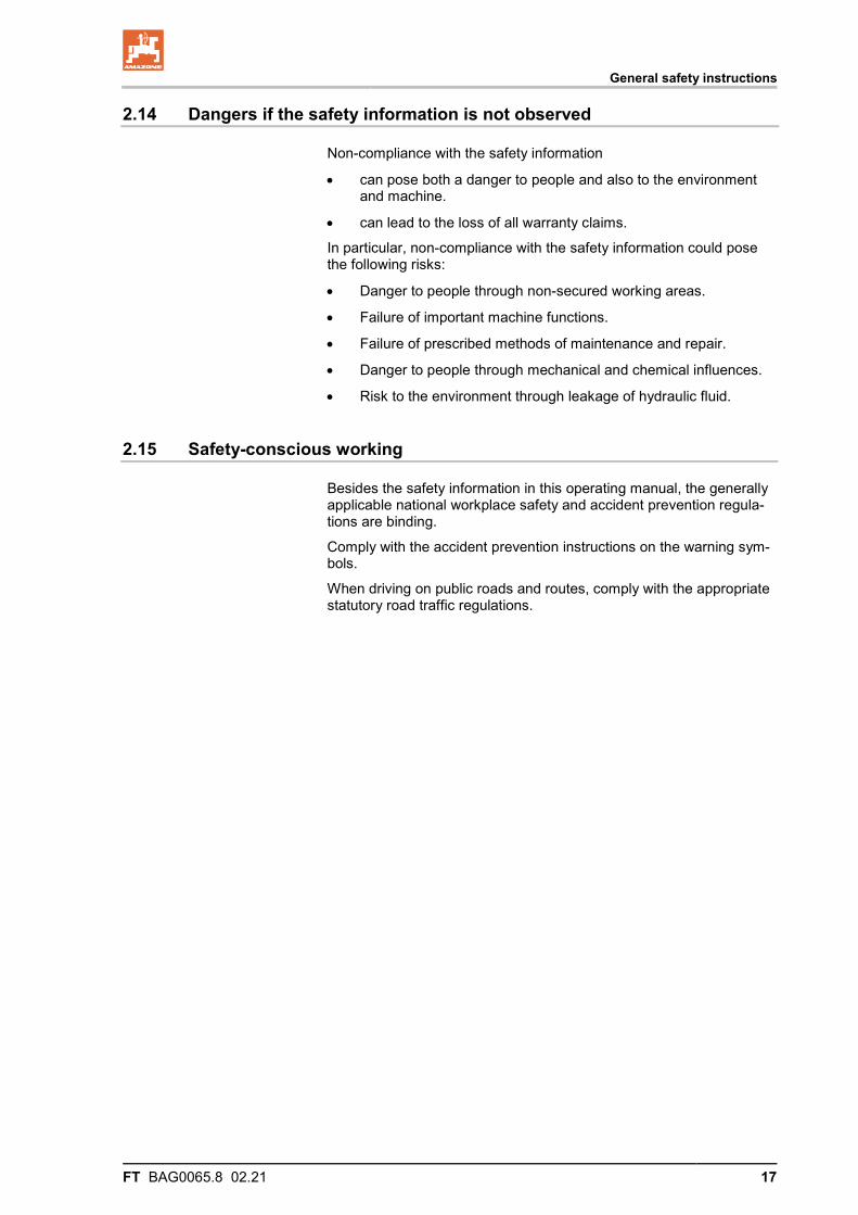
MD 100 This symbol indicates anchorage points for fas-tening slinging gear when loading the machine.
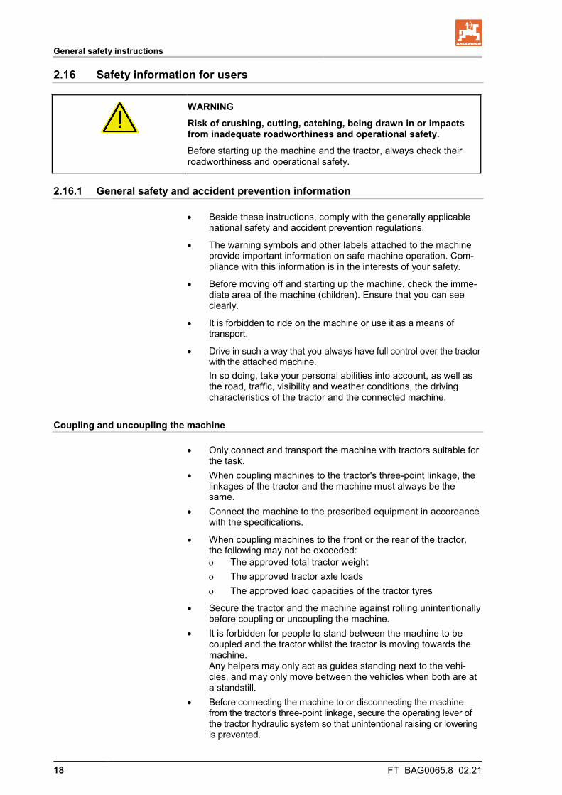
MD 102 Danger from intervention in the machine, e.g. installation, adjusting, troubleshooting, cleaning, maintaining and repairing, due to the tractor and the machine being started unintentionally and rolling. These dangers can cause extremely serious and potentially fatal injuries.
• Secure the tractor and the machine against unintentional start-up and rolling before any intervention in the machine.
• Depending on the type of intervention, read and observe the information in the relevant sections of the operating manual.
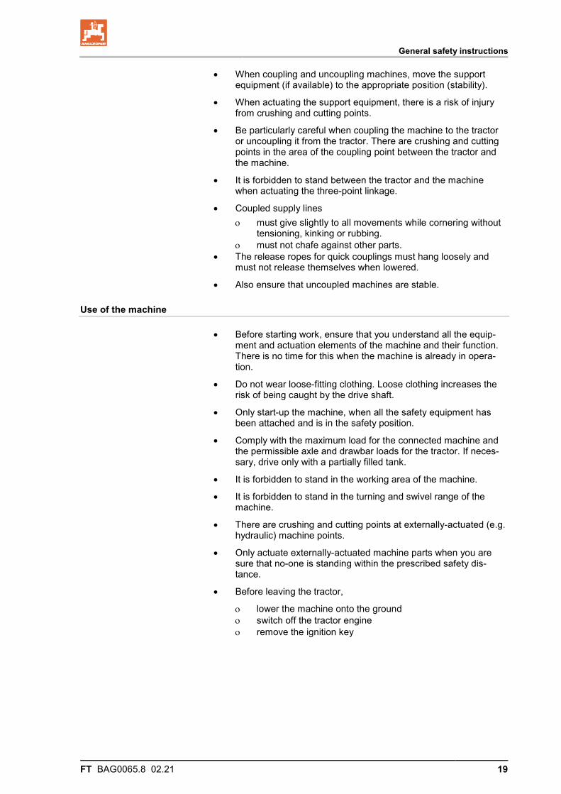
MD 173 Risk of breathing in hazardous materials via poisonous vapours from the spray liquid tank. This danger can cause extremely serious and potentially fatal injuries.
Never climb into the spray liquid tank.
General safety instructions
FT BAG0065.8 02.21 17
2.14 Dangers if the safety information is not observed
Non-compliance with the safety information
• can pose both a danger to people and also to the environment and machine.
• can lead to the loss of all warranty claims.
In particular, non-compliance with the safety information could pose the following risks:
• Danger to people through non-secured working areas.
• Failure of important machine functions.
• Failure of prescribed methods of maintenance and repair.
• Danger to people through mechanical and chemical influences.
• Risk to the environment through leakage of hydraulic fluid.
2.15 Safety-conscious working
Besides the safety information in this operating manual, the generally applicable national workplace safety and accident prevention regula-tions are binding.
Comply with the accident prevention instructions on the warning sym-bols.
When driving on public roads and routes, comply with the appropriate statutory road traffic regulations.
General safety instructions
18 FT BAG0065.8 02.21
2.16 Safety information for users
WARNING Risk of crushing, cutting, catching, being drawn in or impacts from inadequate roadworthiness and operational safety. Before starting up the machine and the tractor, always check their roadworthiness and operational safety.
2.16.1 General safety and accident prevention information
• Beside these instructions, comply with the generally applicable national safety and accident prevention regulations.
• The warning symbols and other labels attached to the machine provide important information on safe machine operation. Com-pliance with this information is in the interests of your safety.
• Before moving off and starting up the machine, check the imme-diate area of the machine (children). Ensure that you can see clearly.
• It is forbidden to ride on the machine or use it as a means of transport.
• Drive in such a way that you always have full control over the tractor with the attached machine.
In so doing, take your personal abilities into account, as well as the road, traffic, visibility and weather conditions, the driving characteristics of the tractor and the connected machine.
Coupling and uncoupling the machine
• Only connect and transport the machine with tractors suitable for the task.
• When coupling machines to the tractor's three-point linkage, the linkages of the tractor and the machine must always be the same.
• Connect the machine to the prescribed equipment in accordance with the specifications.
• When coupling machines to the front or the rear of the tractor, the following may not be exceeded: ο The approved total tractor weight ο The approved tractor axle loads ο The approved load capacities of the tractor tyres
• Secure the tractor and the machine against rolling unintentionally before coupling or uncoupling the machine.
• It is forbidden for people to stand between the machine to be coupled and the tractor whilst the tractor is moving towards the machine.
Any helpers may only act as guides standing next to the vehi-cles, and may only move between the vehicles when both are at a standstill.
• Before connecting the machine to or disconnecting the machine from the tractor's three-point linkage, secure the operating lever of the tractor hydraulic system so that unintentional raising or lowering is prevented.
General safety instructions
FT BAG0065.8 02.21 19
• When coupling and uncoupling machines, move the support equipment (if available) to the appropriate position (stability).
• When actuating the support equipment, there is a risk of injury from crushing and cutting points.
• Be particularly careful when coupling the machine to the tractor or uncoupling it from the tractor. There are crushing and cutting points in the area of the coupling point between the tractor and the machine.
• It is forbidden to stand between the tractor and the machine when actuating the three-point linkage.
• Coupled supply lines ο must give slightly to all movements while cornering without
tensioning, kinking or rubbing. ο must not chafe against other parts.
• The release ropes for quick couplings must hang loosely and must not release themselves when lowered.
• Also ensure that uncoupled machines are stable.
Use of the machine
• Before starting work, ensure that you understand all the equip-ment and actuation elements of the machine and their function. There is no time for this when the machine is already in opera-tion.
• Do not wear loose-fitting clothing. Loose clothing increases the risk of being caught by the drive shaft.
• Only start-up the machine, when all the safety equipment has been attached and is in the safety position.
• Comply with the maximum load for the connected machine and the permissible axle and drawbar loads for the tractor. If neces-sary, drive only with a partially filled tank.
• It is forbidden to stand in the working area of the machine.
• It is forbidden to stand in the turning and swivel range of the machine.
• There are crushing and cutting points at externally-actuated (e.g. hydraulic) machine points.
• Only actuate externally-actuated machine parts when you are sure that no-one is standing within the prescribed safety dis-tance.
• Before leaving the tractor,
ο lower the machine onto the ground ο switch off the tractor engine ο remove the ignition key
General safety instructions
20 FT BAG0065.8 02.21
Machine transportation
• Comply with the national road traffic regulations when using public highways.
• Before moving off, check: ο the correct connection of the supply lines ο the lighting system for damage, function and cleanliness ο the brake and hydraulic system for visible damage ο that the parking brake is completely disengaged ο the function of the brake system
• Ensure that the tractor has sufficient steering and braking power. Any machines and front/rear weights connected to the tractor
influence the driving behaviour and the steering and braking power of the tractor.
• If necessary, use front weights. The front tractor axle must always be loaded with at least 20% of
the tractor empty weight, in order to ensure sufficient steering power.
• Always fix the front or rear weights to the intended fixing points according to regulations.
• Comply with the maximum load for the connected machine and the approved axle and drawbar loads for the tractor.
• The tractor must guarantee the prescribed brake delay for the loaded vehicle combination (tractor plus connected machine).
• Check the brake power before moving off.
• When turning corners with the machine connected, take the broad load and balance weight of the machine into account.
• If the machine is fixed to the tractor's three-point linkage or lower links, before moving off, ensure sufficient side locking of the trac-tor lower links.
• Before moving off, move all the swivellable machine parts to the transport position.
• Before moving off, secure all swivellable machine parts in the transport position against dangerous position changes. Use the transport safety catches intended for this.
• Before moving off, secure the operating lever of the three-point hydraulic system against the unintentional raising or lowering of the connected machine.
• Check that the transport equipment, e.g. lighting, warning equipment and protective equipment, is correctly mounted on the machine.
• Carry out a visual check that the upper and lower link pins are firmly fixed with the linchpin against unintentional release.
• Adjust your driving speed to the prevailing conditions. • Before driving downhill, switch to a low gear.
• Before moving off, always switch off independent wheel braking (lock the pedals).
General safety instructions
FT BAG0065.8 02.21 21
2.16.2 Field sprayer operation
• Observe the recommendations of the crop protection agent manufacturer in respect of
ο protective clothing
ο warning information on exposure to crop protection agents
ο regulations on dosing, applications and cleaning
• When handling crop protection products, observe the safety instructions provided by the crop protection product manufactur-er.
• It is forbidden to use unauthorised crop protection products.
• Observe the information in the German Plant Protection Law.
• Never open lines which are under pressure.
• Only use genuine AMAZONE replacement hoses which stand up to chemical, mechanical and thermal requirements. Only use hose clamps made from V2A for installation.
• The nominal volume of the spray liquid tank must not be ex-ceeded during filling.
• When there will be exposure to crop protection agent, wear the proper protective clothing, i.e. gloves, overalls, safety glasses, etc.
• When using tractors with a cab with ventilation fans, replace the fresh air filters with activated carbon filters.
• Observe the information on the compatibility of crop protec-tion agents and substances for the field sprayer.
• Do not spray any crop protection agents which have a ten-dency to stick together or set.
• Do not fill field sprayers with water from bodies of water which are open to the public, for the protection of people, animals and the environment.
• Only fill field sprayers
ο using a free flow from the mains water supply.
ο using genuine AMAZONE filling equipment.
General safety instructions
22 FT BAG0065.8 02.21
2.16.3 Cleaning, maintenance and repairs
• Due to toxic vapours in the spray liquid tank, climbing into the spray liquid tank is always forbidden.
• Repair work in the spray liquid tank must only be carried out by a specialist workshop!
• Only carry out cleaning, maintenance and repair work on the machine when
ο the drive is switched off
ο the tractor engine has come to a complete stop
ο the ignition key has been removed
ο the machine connector has been removed from the on-board computer
• Regularly check the nuts and bolts for firm seating and retighten them as necessary.
• Secure the raised machine and/or raised machine parts against unintentional lowering before performing any cleaning, mainte-nance or repair work on the machine.
• When replacing work tools with blades, use suitable tools and gloves.
• Dispose of oils, greases and filters in the appropriate way.
• Disconnect the cable to the tractor generator and battery before carrying out electrical welding work on the tractor and on at-tached machines.
• Spare parts must meet at least the specified technical require-ments of AMAZONEN-WERKE. This is ensured through the use of genuine AMAZONE spare parts.
• When repairing field sprayers which have been used for liquid fertiliser application with ammonium nitrate / urea solution, ob-serve the following points:
Residues of ammonium nitrate / urea solutions may form salts by the evaporation of the water on or in the spray liquid tank. This produces pure ammonium nitrate and urea. In its undiluted form, ammonium nitrate is explosive when combined with organic sub-stances, e.g. urea, and subjected to critical temperatures during repair work (e.g. welding, grinding, filing).
This danger can be eliminated by thoroughly washing out the spray liquid tank or the parts intended for repair with water, be-cause the salt of the ammonium nitrate / urea solution is water-soluble. For this reason, clean the field sprayer thoroughly with water before carrying out repair work.
Loading and unloading
FT BAG0065.8 02.21 23
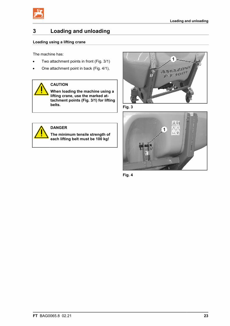
3 Loading and unloading
Loading using a lifting crane
The machine has:
• Two attachment points in front (Fig. 3/1)
• One attachment point in back (Fig. 4/1),
Fig. 3
Fig. 4
CAUTION When loading the machine using a lifting crane, use the marked at-tachment points (Fig. 3/1) for lifting belts.
DANGER The minimum tensile strength of each lifting belt must be 100 kg!
Product description
24 FT BAG0065.8 02.21
4 Product description 4.1 Overview
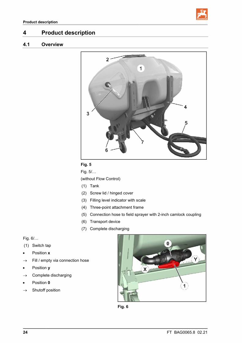
Fig. 5
Fig. 5/…
(without Flow Control)
(1) Tank
(2) Screw lid / hinged cover
(3) Filling level indicator with scale
(4) Three-point attachment frame
(5) Connection hose to field sprayer with 2-inch camlock coupling
(6) Transport device
(7) Complete discharging
Fig. 6/…
(1) Switch tap
• Position x
→ Fill / empty via connection hose
• Position y
→ Complete discharging
• Position 0
→ Shutoff position
Fig. 6
Product description
FT BAG0065.8 02.21 25
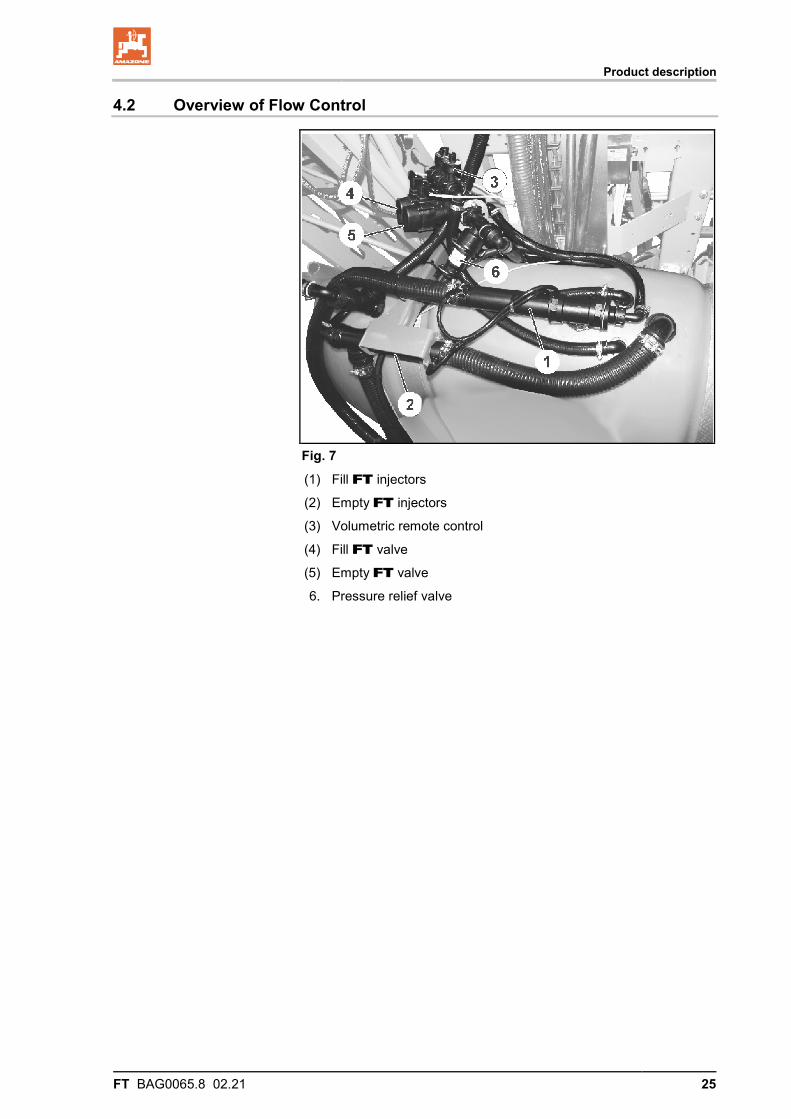
4.2 Overview of Flow Control
Fig. 7 (1) Fill FT injectors
(2) Empty FT injectors
(3) Volumetric remote control
(4) Fill FT valve
(5) Empty FT valve
6. Pressure relief valve
Product description
26 FT BAG0065.8 02.21
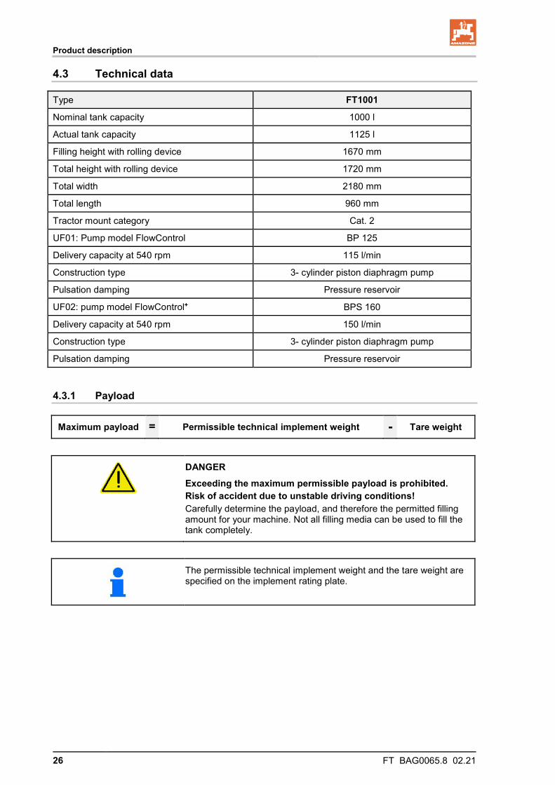
4.3 Technical data
Type FT1001
Nominal tank capacity 1000 l
Actual tank capacity 1125 l
Filling height with rolling device 1670 mm
Total height with rolling device 1720 mm
Total width 2180 mm
Total length 960 mm
Tractor mount category Cat. 2
UF01: Pump model FlowControl BP 125
Delivery capacity at 540 rpm 115 l/min
Construction type 3- cylinder piston diaphragm pump
Pulsation damping Pressure reservoir
UF02: pump model FlowControl+ BPS 160
Delivery capacity at 540 rpm 150 l/min
Construction type 3- cylinder piston diaphragm pump
Pulsation damping Pressure reservoir
4.3.1 Payload
Maximum payload = Permissible technical implement weight - Tare weight
DANGER Exceeding the maximum permissible payload is prohibited. Risk of accident due to unstable driving conditions! Carefully determine the payload, and therefore the permitted filling amount for your machine. Not all filling media can be used to fill the tank completely.
The permissible technical implement weight and the tare weight are specified on the implement rating plate.
Product description
FT BAG0065.8 02.21 27
4.4 Intended use
The FT1001 front tank
• is intended for transporting: ο Water and liquid fertiliser ο Crop protection agents (only with Flow Control)
• is designed exclusively for agricultural use for treating field crops in combination with the AMAZONE UF field sprayer.
• is attached to the category 2 front hydraulic system of the tractor and operated by one person.
Sloping terrain can be traversed as follows: • Along the contours Direction of travel to left 20 %
Direction of travel to right 20 %
• Along the gradient Up the slope 20 %
Down the slope 20 %
The intended use also includes:
• Compliance with all the instructions in this operating manual.
• Execution of inspection and maintenance work.
• Exclusive use of genuine AMAZONE spare parts.
Other uses to those specified above are forbidden and shall be con-sidered as improper.
For any damage resulting from improper use:
• the operator bears the sole responsibility,
• the manufacturer will assume no liability whatsoever.
Product description
28 FT BAG0065.8 02.21
4.5 Danger areas and danger points
The danger area is the area around the machine in which people can be caught by: • work movements made by the machine • unintentional rolling of the tractor and the machine
Within the machine danger area, there are danger points with perma-nent or unexpected risks. Warning symbols indicate these danger points and warn against residual dangers, which cannot be eliminated for practical reasons. In such cases, the special safety regulations in the appropriate section are valid.
No-one may stand in the machine danger area: • if the tractor engine is running with the PTO shaft / hydraulic
system connected. • if the tractor and machine are not protected against unintentional
start-up and rolling.
The operating person may only move the machine or switch or drive the tools from the transport position to the working position or vice-versa when there is no-one in the machine danger area.
Danger points exist: • Between the tractor and the front tank, especially when coupling
and uncoupling.
• In the spray liquid tank due to poisonous vapours.
• Underneath raised, unsecured machines.
Product description
FT BAG0065.8 02.21 29
4.6 Machine rating plate
The following information is specified on the rating plate and the CE mark:
(1) Implement number
(2) Vehicle identification number
(3) Product
(4) Permissible technical implement weight
(5) Tare weight kg
(6) Model year
(7) Year of manufacture
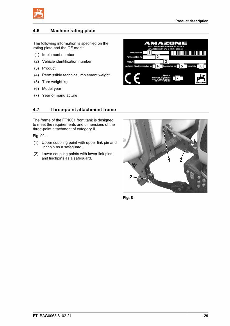
4.7 Three-point attachment frame
The frame of the FT1001 front tank is designed to meet the requirements and dimensions of the three-point attachment of category II.
Fig. 9/…
(1) Upper coupling point with upper link pin and linchpin as a safeguard.
(2) Lower coupling points with lower link pins and linchpins as a safeguard.
Fig. 8
Product description
30 FT BAG0065.8 02.21
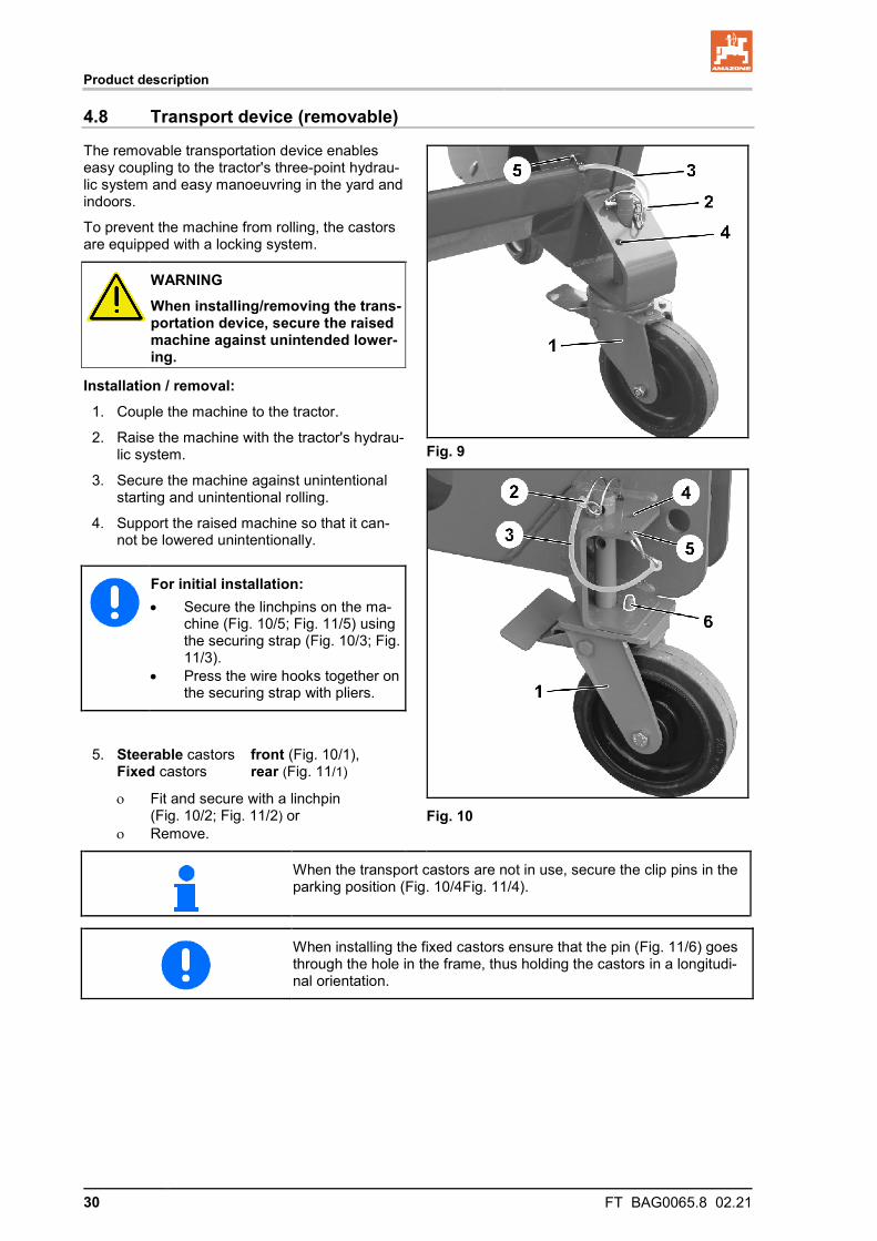
4.8 Transport device (removable)
The removable transportation device enables easy coupling to the tractor's three-point hydrau-lic system and easy manoeuvring in the yard and indoors.
To prevent the machine from rolling, the castors are equipped with a locking system.
Fig. 9
Fig. 10
WARNING When installing/removing the trans-portation device, secure the raised machine against unintended lower-ing.
Installation / removal: 1. Couple the machine to the tractor.
2. Raise the machine with the tractor's hydrau-lic system.
3. Secure the machine against unintentional starting and unintentional rolling.
4. Support the raised machine so that it can-not be lowered unintentionally.
For initial installation: • Secure the linchpins on the ma-
chine (Fig. 10/5; Fig. 11/5) using the securing strap (Fig. 10/3; Fig. 11/3).
• Press the wire hooks together on the securing strap with pliers.
5. Steerable castors front (Fig. 10/1), Fixed castors rear (Fig. 11/1)
ο Fit and secure with a linchpin (Fig. 10/2; Fig. 11/2) or
ο Remove.
When the transport castors are not in use, secure the clip pins in the parking position (Fig. 10/4Fig. 11/4).
When installing the fixed castors ensure that the pin (Fig. 11/6) goes through the hole in the frame, thus holding the castors in a longitudi-nal orientation.
Product description
FT BAG0065.8 02.21 31
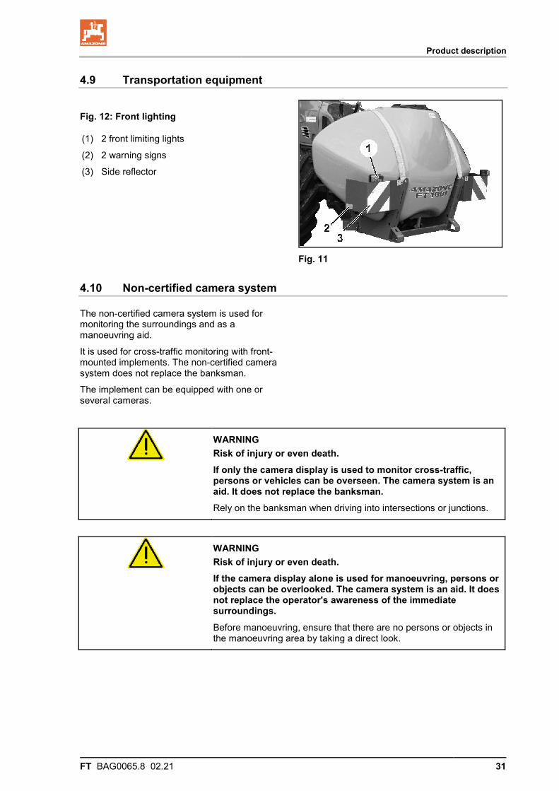
4.9 Transportation equipment
Fig. 12: Front lighting
(1) 2 front limiting lights
(2) 2 warning signs
(3) Side reflector
Fig. 11
4.10 Non-certified camera system
The non-certified camera system is used for monitoring the surroundings and as a manoeuvring aid.
It is used for cross-traffic monitoring with front-mounted implements. The non-certified camera system does not replace the banksman.
The implement can be equipped with one or several cameras.
WARNING Risk of injury or even death. If only the camera display is used to monitor cross-traffic, persons or vehicles can be overseen. The camera system is an aid. It does not replace the banksman. Rely on the banksman when driving into intersections or junctions.
WARNING Risk of injury or even death. If the camera display alone is used for manoeuvring, persons or objects can be overlooked. The camera system is an aid. It does not replace the operator's awareness of the immediate surroundings. Before manoeuvring, ensure that there are no persons or objects in the manoeuvring area by taking a direct look.
UF01 and FT 1001 without Flow Control
32 FT BAG0065.8 02.21
5 UF01 and FT 1001 without Flow Control
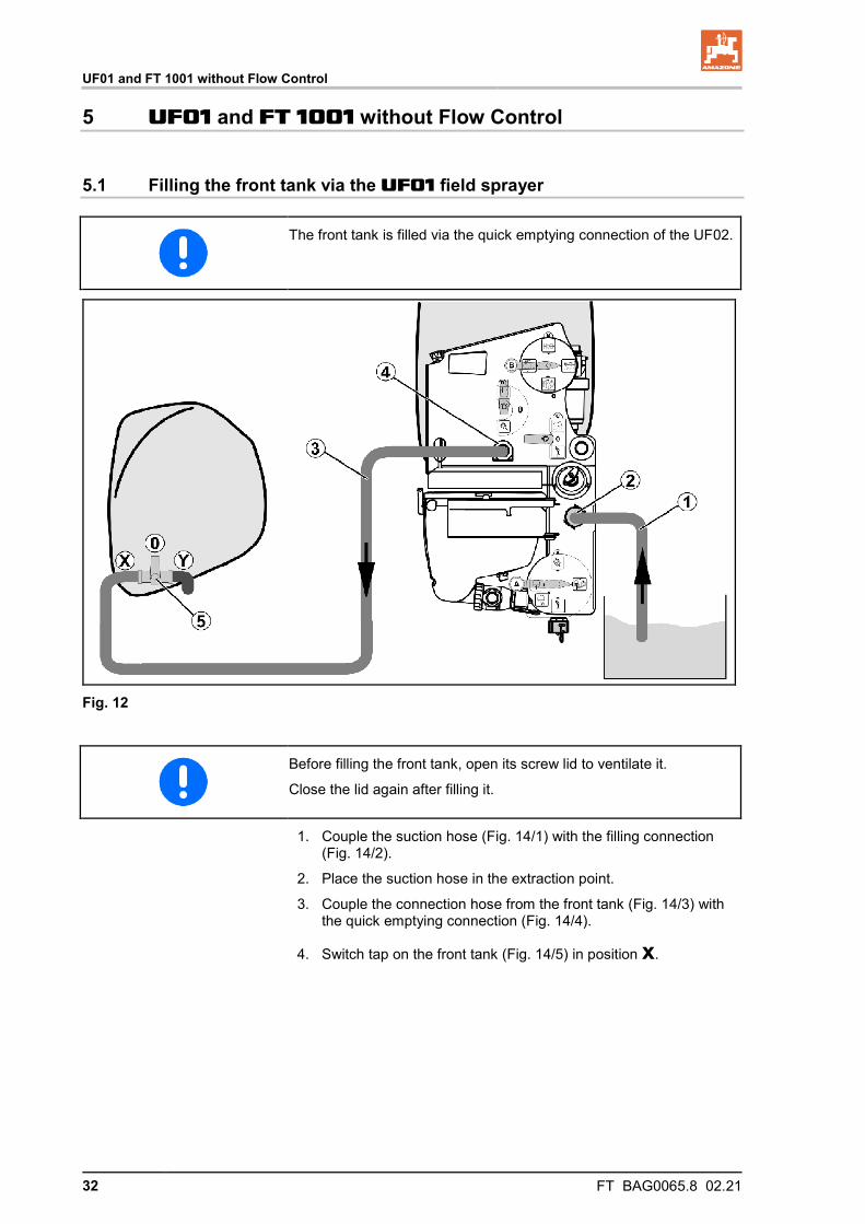
5.1 Filling the front tank via the UF01 field sprayer
The front tank is filled via the quick emptying connection of the UF02.
Fig. 12
Before filling the front tank, open its screw lid to ventilate it.
Close the lid again after filling it.
1. Couple the suction hose (Fig. 14/1) with the filling connection (Fig. 14/2).
2. Place the suction hose in the extraction point.
3. Couple the connection hose from the front tank (Fig. 14/3) with the quick emptying connection (Fig. 14/4).
4. Switch tap on the front tank (Fig. 14/5) in position x.
UF01 and FT 1001 without Flow Control
FT BAG0065.8 02.21 33
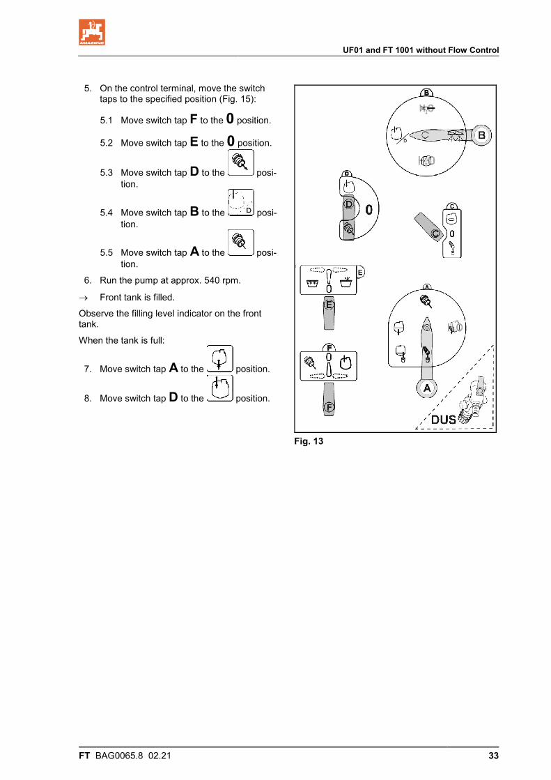
5. On the control terminal, move the switch taps to the specified position (Fig. 15):
5.1 Move switch tap F to the 0 position.
5.2 Move switch tap E to the 0 position.
5.3 Move switch tap D to the posi-tion.
5.4 Move switch tap B to the posi-tion.
5.5 Move switch tap A to the posi-tion.
6. Run the pump at approx. 540 rpm.
→ Front tank is filled.
Observe the filling level indicator on the front tank.
When the tank is full:
7. Move switch tap A to the position.
8. Move switch tap D to the position.
Fig. 13
UF01 and FT 1001 without Flow Control
34 FT BAG0065.8 02.21
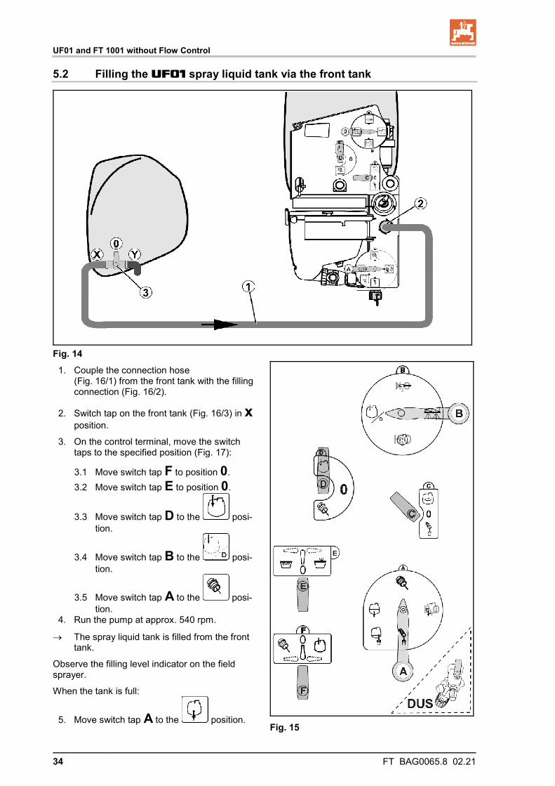
5.2 Filling the UF01 spray liquid tank via the front tank
Fig. 14 1. Couple the connection hose
(Fig. 16/1) from the front tank with the filling connection (Fig. 16/2).
2. Switch tap on the front tank (Fig. 16/3) in x position.
3. On the control terminal, move the switch taps to the specified position (Fig. 17):
3.1 Move switch tap F to position 0. 3.2 Move switch tap E to position 0.
3.3 Move switch tap D to the posi-tion.
3.4 Move switch tap B to the posi-tion.
3.5 Move switch tap A to the posi-tion.
4. Run the pump at approx. 540 rpm.
→ The spray liquid tank is filled from the front tank.
Observe the filling level indicator on the field sprayer.
When the tank is full:
5. Move switch tap A to the position.
Fig. 15
UF01 and FT1001 with Flow Control (optional)
FT BAG0065.8 02.21 35
6 UF01 and FT1001 with Flow Control (optional)
With Flow Control, the front tank is used in combination with the in-cab terminal as an additional container for spray liquid.
Flow Control operates in two modes:
• Automatic mode • Manual mode
Before using the front tank with Flow Control on the in-cab terminal select the UF01 machine type with FT in the setup menu.
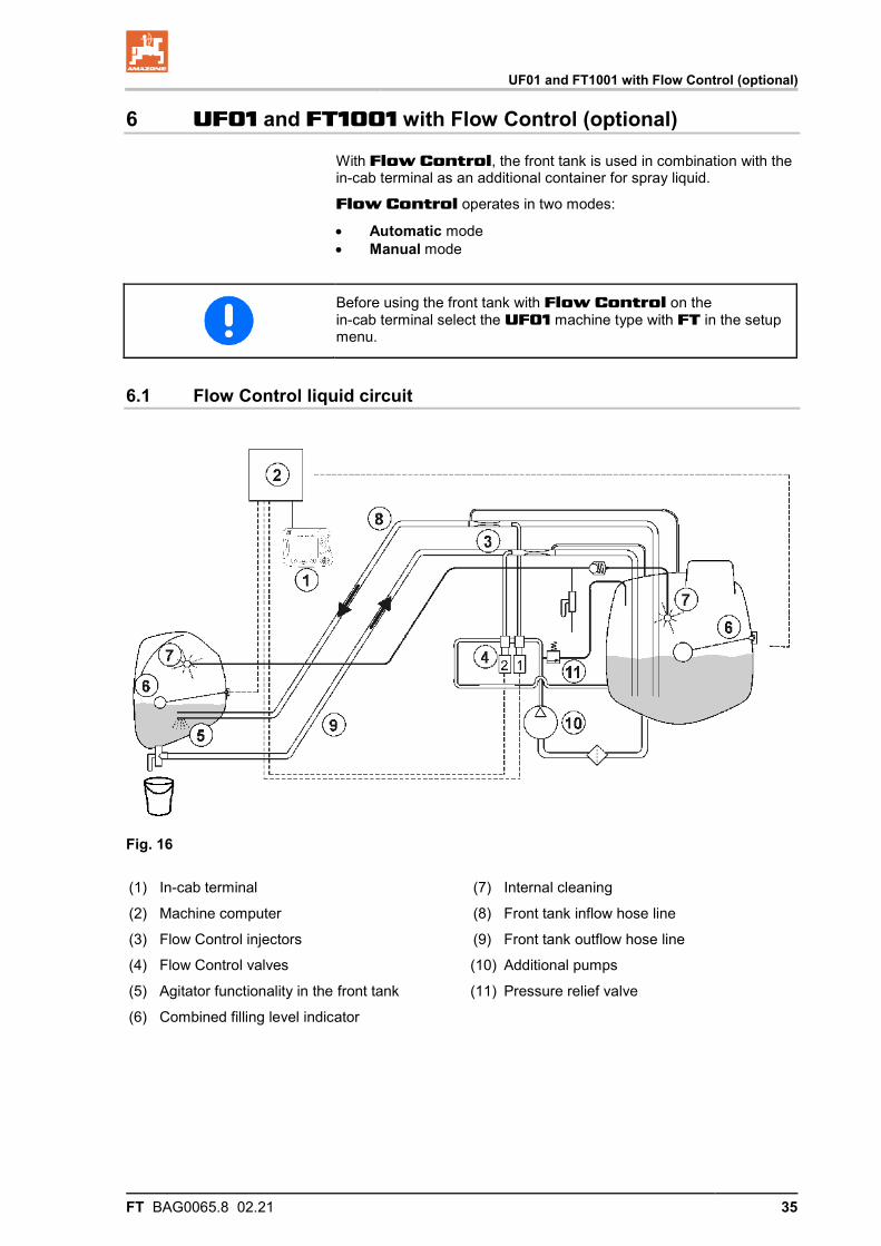
6.1 Flow Control liquid circuit
Fig. 16
(1) In-cab terminal
(2) Machine computer
(3) Flow Control injectors
(4) Flow Control valves
(5) Agitator functionality in the front tank
(6) Combined filling level indicator
(7) Internal cleaning
(8) Front tank inflow hose line
(9) Front tank outflow hose line
(10) Additional pumps
(11) Pressure relief valve
UF01 and FT1001 with Flow Control (optional)
36 FT BAG0065.8 02.21
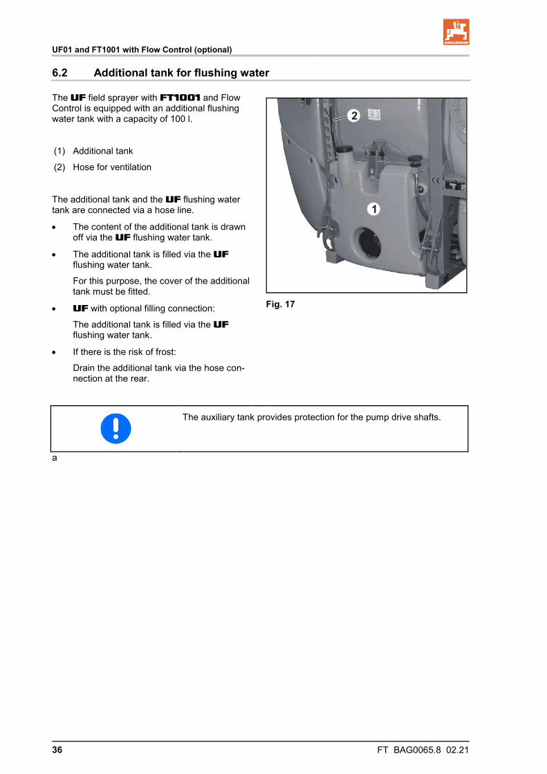
6.2 Additional tank for flushing water
The UF field sprayer with FT1001 and Flow Control is equipped with an additional flushing water tank with a capacity of 100 l.
(1) Additional tank
(2) Hose for ventilation
The additional tank and the UF flushing water tank are connected via a hose line.
• The content of the additional tank is drawn off via the UF flushing water tank.
• The additional tank is filled via the UF flushing water tank.
For this purpose, the cover of the additional tank must be fitted.
• UF with optional filling connection:
The additional tank is filled via the UF flushing water tank.
• If there is the risk of frost:
Drain the additional tank via the hose con-nection at the rear.
1
2
Fig. 17
The auxiliary tank provides protection for the pump drive shafts.
a
UF01 and FT1001 with Flow Control (optional)
FT BAG0065.8 02.21 37
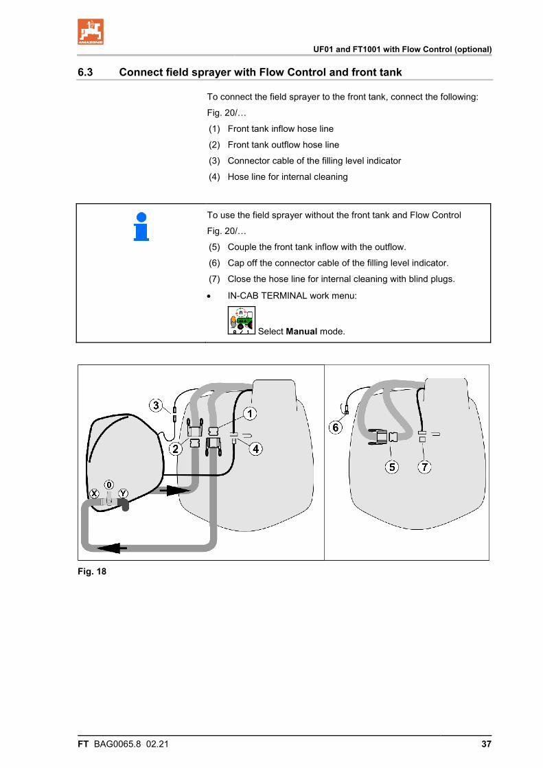
6.3 Connect field sprayer with Flow Control and front tank
To connect the field sprayer to the front tank, connect the following:
Fig. 20/…
(1) Front tank inflow hose line
(2) Front tank outflow hose line
(3) Connector cable of the filling level indicator
(4) Hose line for internal cleaning
To use the field sprayer without the front tank and Flow Control
Fig. 20/…
(5) Couple the front tank inflow with the outflow.
(6) Cap off the connector cable of the filling level indicator.
(7) Close the hose line for internal cleaning with blind plugs.
• IN-CAB TERMINAL work menu:
Select Manual mode.
Fig. 18
UF01 and FT1001 with Flow Control (optional)
38 FT BAG0065.8 02.21
6.4 Automatic mode
Before starting to spray, circulate the spray liquid for at least 5 minutes with agitating effect in automatic mode.
This ensures uniform active substance concentration.
During use and transport, the field sprayer / front tank combination is operated in Automatic mode.
Functions of Automatic mode:
• Constant circulation of the spray liquid with agitator effect in the front tank.
• Regulation of the fill levels of both containers in spraying opera-tion.
→ Field sprayer container is emptied by up to 30% of its ca-pacity.
→ The front tank fills the field sprayer container to up to 50% of its capacity.
→ The front tank is emptied when the level of the field sprayer container is less than 30% of its capacity.
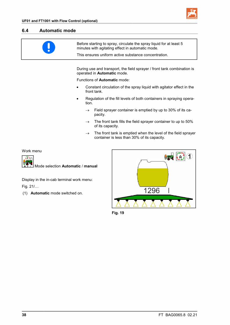
Work menu
Mode selection Automatic / manual
Display in the in-cab terminal work menu:
Fig. 21/…
(1) Automatic mode switched on.
Fig. 19
UF01 and FT1001 with Flow Control (optional)
FT BAG0065.8 02.21 39
6.5 Manual mode
In manual mode, the spray liquid distribution to both containers is controlled by the operator.
This is accomplished by these functions:
• Pump to front
• Pump to rear
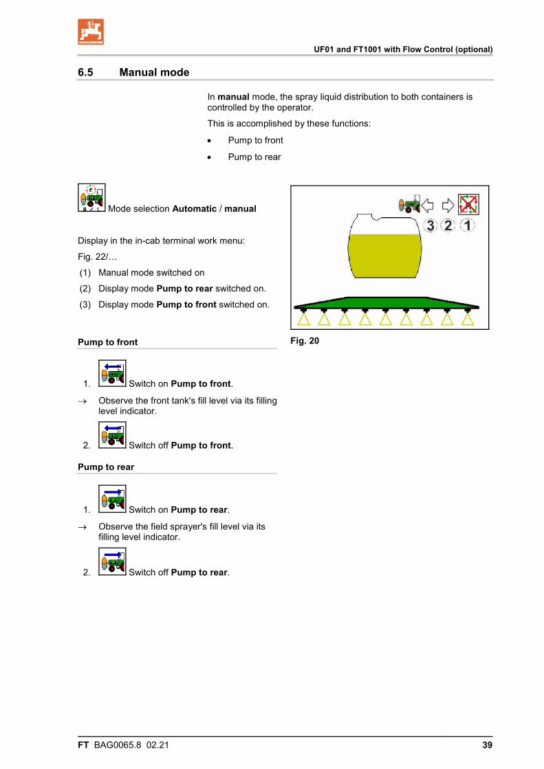
Mode selection Automatic / manual
Display in the in-cab terminal work menu:
Fig. 22/…
(1) Manual mode switched on
(2) Display mode Pump to rear switched on.
(3) Display mode Pump to front switched on.
Pump to front
1. Switch on Pump to front.
→ Observe the front tank's fill level via its filling level indicator.
2. Switch off Pump to front.
Pump to rear
1. Switch on Pump to rear.
→ Observe the field sprayer's fill level via its filling level indicator.
2. Switch off Pump to rear.
Fig. 20
UF01 and FT1001 with Flow Control (optional)
40 FT BAG0065.8 02.21
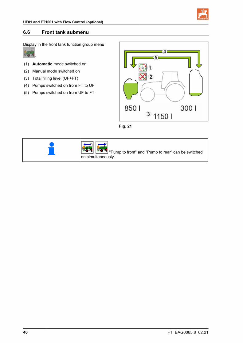
6.6 Front tank submenu
Display in the front tank function group menu
:
(1) Automatic mode switched on.
(2) Manual mode switched on
(3) Total filling level (UF+FT)
(4) Pumps switched on from FT to UF
(5) Pumps switched on from UF to FT
Fig. 21
, "Pump to front" and "Pump to rear" can be switched on simultaneously.
UF01 and FT1001 with Flow Control (optional)
FT BAG0065.8 02.21 41
6.7 Filling
See operating manual for field sprayer ISOBUS software.
CAUTION When the UF front tank combination is filled, the UF tank nomi-nal capacity must not be exceeded. Automatic pumping during operation would overfill the UF tank.
The front tank is filled via:
• The UF field sprayer,
• The filling menu of the in-cab terminal
→ Refer to the UF and in-cab terminal operating manuals.
Call up the filling menu for this purpose.
To fill the front tank / field sprayer combination:
• The UF container is filled when the UF fill level is < 20%.
• The front tank is filled when the UF fill level is > 20%.
• The UF container is completely filled when the FT fill level = 100% and the spray liquid circulation is switched on.
6.8 Internal cleaning
See operating manual for field sprayer ISOBUS software.
6.9 Failure of a level sensor
When a level sensor fails:
• An alarm signal appears.
• The mode switches from Automatic to manual,
• Both valves of the Flow Control close.
UF02 and FT 1001 without FlowControl
42 FT BAG0065.8 02.21
7 UF02 and FT 1001 without FlowControl
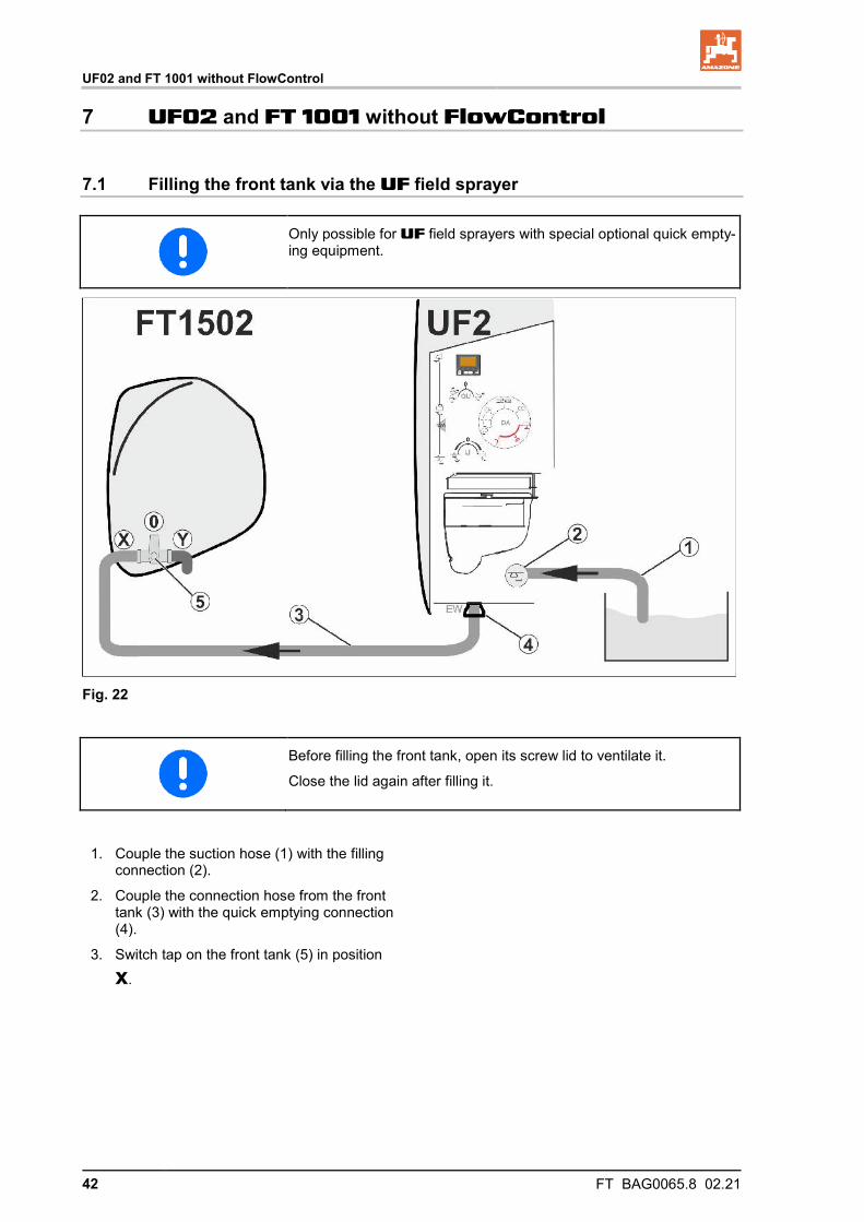
7.1 Filling the front tank via the UF field sprayer
Only possible for UF field sprayers with special optional quick empty-ing equipment.
Fig. 22
Before filling the front tank, open its screw lid to ventilate it.
Close the lid again after filling it.
1. Couple the suction hose (1) with the filling connection (2).
2. Couple the connection hose from the front tank (3) with the quick emptying connection (4).
3. Switch tap on the front tank (5) in position
x.
UF02 and FT 1001 without FlowControl
FT BAG0065.8 02.21 43
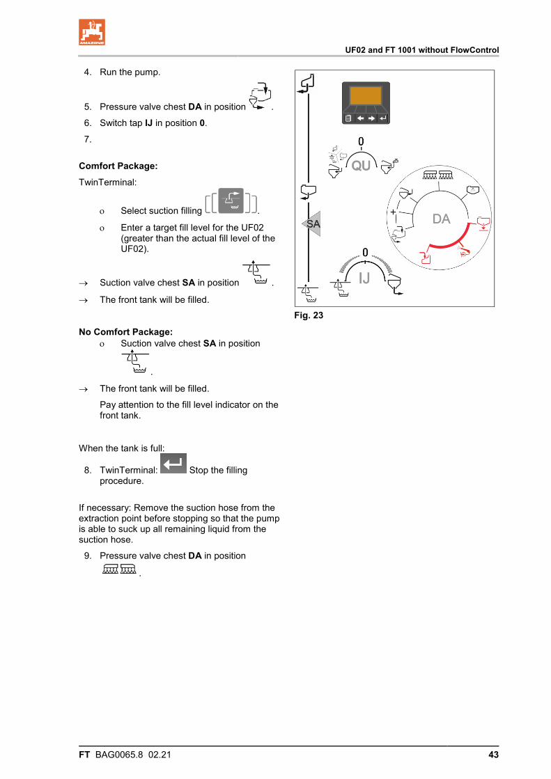
4. Run the pump.
5. Pressure valve chest DA in position .
6. Switch tap IJ in position 0.
7.
Comfort Package: TwinTerminal:
ο Select suction filling .
ο Enter a target fill level for the UF02 (greater than the actual fill level of the UF02).
→ Suction valve chest SA in position .
→ The front tank will be filled.
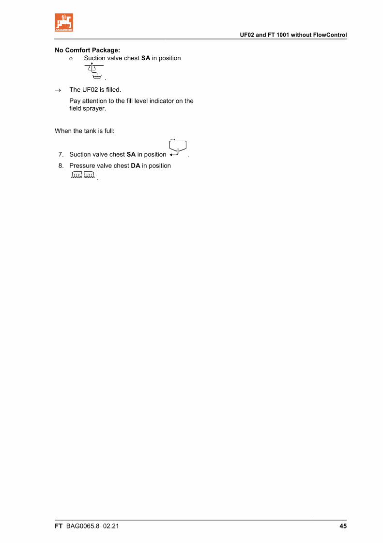
No Comfort Package: ο Suction valve chest SA in position
.
→ The front tank will be filled.
Pay attention to the fill level indicator on the front tank.
When the tank is full:
8. TwinTerminal: Stop the filling procedure.
If necessary: Remove the suction hose from the extraction point before stopping so that the pump is able to suck up all remaining liquid from the suction hose.
9. Pressure valve chest DA in position
.
Fig. 23

UF02 and FT 1001 without FlowControl
44 FT BAG0065.8 02.21
7.2 Filling the UF spray liquid tank via the front tank
Fig. 24 1. Couple the connection hose from the front
tank (1) to the filling connection (2).
2. Switch tap on front tank (3) in position x.
3. Run the pump.
4. Pressure valve chest DA in position .
5. Switch tap IJ in position 0.
6.
Comfort Package: TwinTerminal:
ο Select suction filling .
ο Enter the target fill level for the UF02 and confirm.
→ Suction valve chest SA in position .
→ The UF02 is filled.
Filling of the spray liquid tank stops auto-matically as soon as the target fill level has been reached.
Fig. 25
UF02 and FT 1001 without FlowControl
FT BAG0065.8 02.21 45
No Comfort Package: ο Suction valve chest SA in position
.
→ The UF02 is filled.
Pay attention to the fill level indicator on the field sprayer.
When the tank is full:
7. Suction valve chest SA in position .
8. Pressure valve chest DA in position
.
UF02 and FT 1001 with Flow Control (optional)
46 FT BAG0065.8 02.21
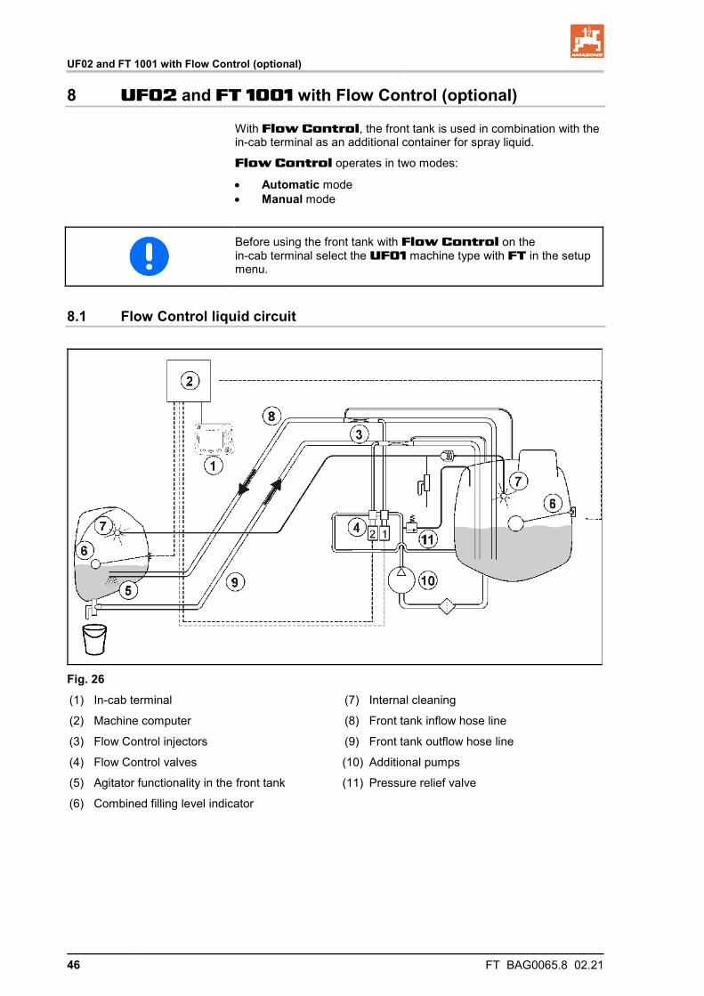
8 UF02 and FT 1001 with Flow Control (optional)
With Flow Control, the front tank is used in combination with the in-cab terminal as an additional container for spray liquid.
Flow Control operates in two modes:
• Automatic mode • Manual mode
Before using the front tank with Flow Control on the in-cab terminal select the UF01 machine type with FT in the setup menu.
8.1 Flow Control liquid circuit
Fig. 26 (1) In-cab terminal
(2) Machine computer
(3) Flow Control injectors
(4) Flow Control valves
(5) Agitator functionality in the front tank
(6) Combined filling level indicator
(7) Internal cleaning
(8) Front tank inflow hose line
(9) Front tank outflow hose line
(10) Additional pumps
(11) Pressure relief valve
UF02 and FT 1001 with Flow Control (optional)
FT BAG0065.8 02.21 47
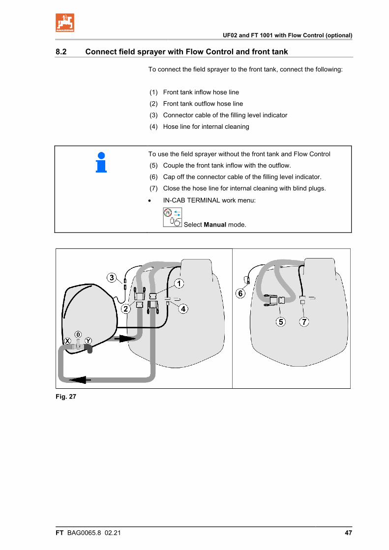
8.2 Connect field sprayer with Flow Control and front tank
To connect the field sprayer to the front tank, connect the following:
(1) Front tank inflow hose line
(2) Front tank outflow hose line
(3) Connector cable of the filling level indicator
(4) Hose line for internal cleaning
To use the field sprayer without the front tank and Flow Control
(5) Couple the front tank inflow with the outflow.
(6) Cap off the connector cable of the filling level indicator.
(7) Close the hose line for internal cleaning with blind plugs.
• IN-CAB TERMINAL work menu:
Select Manual mode.
Fig. 27
UF02 and FT 1001 with Flow Control (optional)
48 FT BAG0065.8 02.21
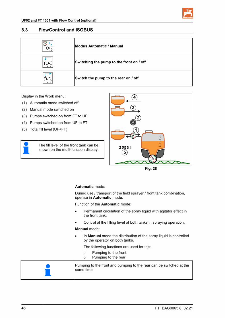
8.3 FlowControl and ISOBUS
Modus Automatic / Manual
Switching the pump to the front on / off
Switch the pump to the rear on / off
Display in the Work menu:
(1) Automatic mode switched off.
(2) Manual mode switched on
(3) Pumps switched on from FT to UF
(4) Pumps switched on from UF to FT
(5) Total fill level (UF+FT)
Fig. 28
The fill level of the front tank can be shown on the multi-function display.
Automatic mode:
During use / transport of the field sprayer / front tank combination, operate in Automatic mode.
Function of the Automatic mode:
• Permanent circulation of the spray liquid with agitator effect in the front tank.
• Control of the filling level of both tanks in spraying operation.
Manual mode:
• In Manual mode the distribution of the spray liquid is controlled by the operator on both tanks.
The following functions are used for this: ο Pumping to the front. ο Pumping to the rear.
Pumping to the front and pumping to the rear can be switched at the same time.
UF02 and FT 1001 with Flow Control (optional)
FT BAG0065.8 02.21 49
For using the field sprayer without front tank, switch off the front tank in the Implement menu.
8.4 Filling
See operating manual for field sprayer ISOBUS software.
The front tank is filled via the field sprayer UF.
• Before filling the front tank and field sprayer together, adjust the indicator limit for the fill level.
• To avoid overfilling of the front tank, the respective valve closes automatically when the nominal volume is reached.
8.5 Internal cleaning
The front tank is equipped with an internal cleaning that is operated parallel to the field sprayer.
→ See the operating manual UF.
During / after internal cleaning:
• Pumping to the rear must be switched on until the front tank is empty.
→ Is carried out automatically on machines with Comfort Package!
• After internal cleaning: perform residual drainage.
8.6 Failure of a fill level sensor
In case of failure of a fill level sensor
• an alarm signal appears,
• switches from Automatic mode to Manual mode,
• closes both valves of the Flow Control.
UF02 and FT 1001 with Flow Control (optional)
50 FT BAG0065.8 02.21
8.7 Pump maintenance
For maintenance of the pump, also refer to the UF operating manual.
8.7.1 Adjust the air pressure in the pressure reservoir
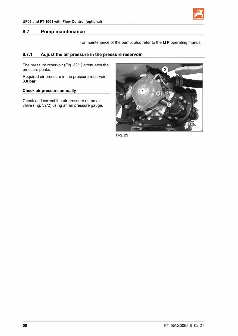
The pressure reservoir (Fig. 32/1) attenuates the pressure peaks.
Required air pressure in the pressure reservoir: 3.0 bar
Check air pressure annually
Check and correct the air pressure at the air valve (Fig. 32/2) using an air pressure gauge.
Fig. 29
UF02 and FT 1001 with Flow Control (optional)
FT BAG0065.8 02.21 51
8.7.2 Replacing the pressure reservoir diaphragm
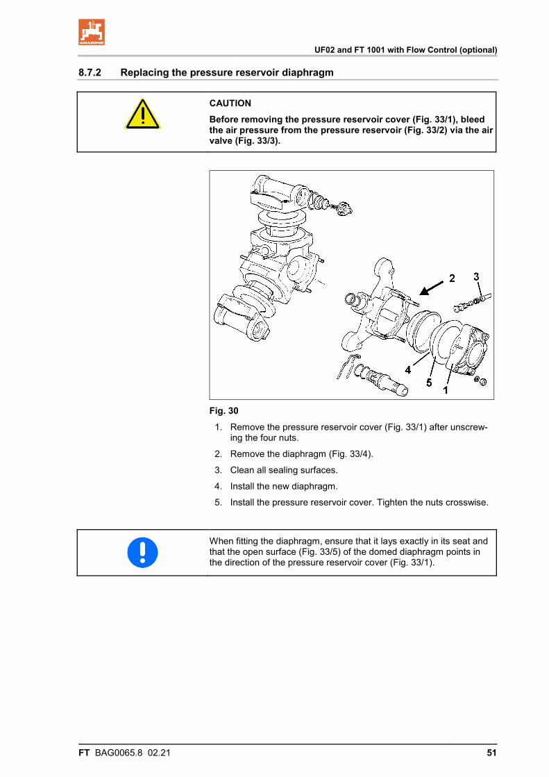
CAUTION Before removing the pressure reservoir cover (Fig. 33/1), bleed the air pressure from the pressure reservoir (Fig. 33/2) via the air valve (Fig. 33/3).
Fig. 30
1. Remove the pressure reservoir cover (Fig. 33/1) after unscrew-ing the four nuts.
2. Remove the diaphragm (Fig. 33/4).
3. Clean all sealing surfaces.
4. Install the new diaphragm.
5. Install the pressure reservoir cover. Tighten the nuts crosswise.
When fitting the diaphragm, ensure that it lays exactly in its seat and that the open surface (Fig. 33/5) of the domed diaphragm points in the direction of the pressure reservoir cover (Fig. 33/1).
Commissioning
52 FT BAG0065.8 02.21
9 Commissioning
This section contains information • on commissioning your machine. • on checking if it is possible to connect the machine to your trac-
tor.
• Before operating the machine for the first time the operator must have read and understood the operating manual.
• Comply with the section "Safety information for the user", starting on page 18 when ο coupling and uncoupling the machine ο transporting the machine ο using the machine
• Only couple and transport the machine to a tractor which is suit-able for the task.
• The tractor and machine must meet the national road traffic regulations.
• The operator and the user shall be responsible for compliance with the statutory road traffic regulations.
Refer to the UF field sprayer operating manual, the chapter on put-ting into operation.
Commissioning
FT BAG0065.8 02.21 53
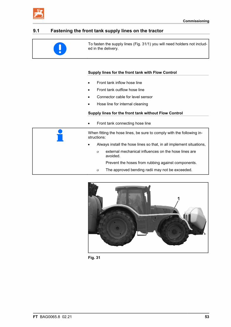
9.1 Fastening the front tank supply lines on the tractor
To fasten the supply lines (Fig. 31/1) you will need holders not includ-ed in the delivery.
Supply lines for the front tank with Flow Control
• Front tank inflow hose line
• Front tank outflow hose line
• Connector cable for level sensor
• Hose line for internal cleaning
Supply lines for the front tank without Flow Control
• Front tank connecting hose line
When fitting the hose lines, be sure to comply with the following in-structions:
• Always install the hose lines so that, in all implement situations,
ο external mechanical influences on the hose lines are avoided.
Prevent the hoses from rubbing against components.
ο The approved bending radii may not be exceeded.
Fig. 31
Coupling and uncoupling the machine
54 FT BAG0065.8 02.21
10 Coupling and uncoupling the machine
When coupling and uncoupling the machine, comply with the section "Safety information for the user", page 18.
WARNING Risk of crushing from unintentional starting and rolling of the tractor and machine when coupling or uncoupling the machine. When coupling or uncoupling the machine, secure the tractor and machine against unintentional start-up and rolling before entering the danger area between the tractor and machine; refer to the UF operat-ing manual.
WARNING Risk of crushing between the rear of the tractor and the machine when coupling and uncoupling the machine. Only actuate the operator controls for the tractor's three-point linkage • from the intended workstation. • if you are outside of the danger area between the tractor and the
machine.
10.1 Coupling the machine
WARNING Risk of breaking during operation, insufficient stability and in-sufficient tractor steering and braking power from improper use of the tractor. You may only connect the machine to tractors suitable for this pur-pose. Refer to the UF operating manual chapter "Checking the suita-bility of the tractor".
WARNING Risk of crushing when coupling the machine and standing be-tween the tractor and the machine. Instruct people to leave the danger area between the tractor and the machine before you approach the machine.
Any helpers may only act as guides standing next to the tractor and the machine, and may only move between the vehicles when both are at a standstill.
Coupling and uncoupling the machine
FT BAG0065.8 02.21 55
WARNING Risk of crushing, being caught or pulled in, or impact when the machine is unexpectedly released from the tractor. • Use the intended equipment to connect the tractor and the ma-
chine in the proper way. • When coupling the machine to the tractor's three-point hydraulic
system, ensure that the attachment categories of the tractor and the machine are the same.
Upgrade the category II lower link pins on the machine to cate-gory III using reducing sleeves if your tractor is equipped with category III three-point hydraulics.
• Only use the upper and lower link pins provided to couple up the machine (original pins).
• Check the upper and lower link pins for visible defects whenever the machine is coupled. Replace the upper and lower link pins in the event of clearly visible wear.
• Secure the upper link pin and lower link pins in the attachment points of the three-point attachment frame against unintentional detachment using a linchpin.
• Perform a visual inspection to ensure that the upper and lower link hooks are correctly locked before reversing the tractor.
1. Secure the machine against unintentional rolling.
2. Always check for visible damage when coupling the machine:
3. Fasten the ball sleeves via the lower link pins in the hinging points of the three-point attachment frame.
4. Secure each of the ball sleeves with linchpins to ensure that they do not accidentally come loose.
5. Direct people out of the danger area between the tractor and machine before you approach the machine with the tractor.
6. Drive the tractor up to the machine, so that you can couple the top link.
7. Use bolts to couple the top link with the upper hinging point of the three-point attachment frame.
8. Secure the top link with a linchpin.
9. Align the machine so that the lower hinging points of the ma-chine hold the lower link hooks of the tractor.
10. Raise the three-point hydraulic system of the tractor until the lower link hooks receive the ball sleeves and automatically inter-lock.
11. Lift the front tank into its working position.
12. Direct people out of the danger area of the machine.
13. Perform a visual inspection to ensure that the upper and lower links are correctly locked before reversing the tractor.
It may be necessary to remove the transportation device for ears treatment or with tall crops to avoid damaging the grains.
Coupling and uncoupling the machine
56 FT BAG0065.8 02.21
10.2 Uncoupling the machine
WARNING Risk of crushing and/or impact
• due to insufficient stability and the machine tipping over on soft or uneven ground.
• due to the machine unintentionally rolling when parked on a transportation device.
• Always place the uncoupled machine with the tank empty on a horizontal storage space with a solid base.
• Secure the machine against unintentionally rolling when parked on a transportation device.
Refer to the section "Transportation device", page 30.
1. Park the empty machine on a horizontal space with a hard sur-face.
2. Uncouple the machine from the tractor.
2.1 Secure the machine against unintentionally rolling. See page 30.
2.2 Relieve the load from the top link.
2.3 Uncouple the top link.
2.4 Relieve the load from the lower link.
2.5 Unlock and uncouple the lower link hooks from the tractor seat.
Transportation
FT BAG0065.8 02.21 57
11 Transportation
WARNING Risk of crushing, cutting, being caught and/or drawn in, or im-pact through unintentional releasing of the coupled machine. Carry out a visual check that the upper and lower link pins are firmly fixed with the linchpin against unintentional release.
WARNING Risk of crushing, cutting, being caught and/or drawn in, or im-pact from tipping and insufficient stability.
• Drive in such a way that you always have full control over the tractor with the attached machine.
In so doing, take your personal abilities into account, as well as the road, traffic, visibility and weather conditions, the driving characteristics of the tractor and the connected machine.
• Before transportation, fasten the side locking device of the trac-tor lower link, so that the connected or coupled machine cannot swing back and forth.
WARNING Risk of breaking during operation, insufficient stability and in-sufficient tractor steering and braking power from improper use of the tractor. These risks pose serious injuries or death.
Comply with the maximum load of the connected machine and the permissible axle and drawbar loads of the tractor. If necessary, drive only with a partially filled tank.
• Installation of the front tank may result in restricted field of vi-sion.
• Equip the tractor with an additional low-beam light in the event that attaching the front tank covers the tractor's low-beam light.
• Equip the front tank with additional turn indicators and limiting lights in the event that attaching the front tank covers those on the tractor.
Transportation
58 FT BAG0065.8 02.21
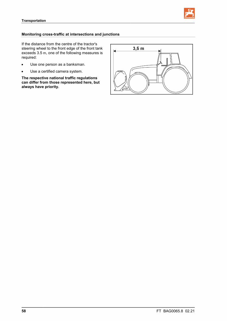
Monitoring cross-traffic at intersections and junctions
If the distance from the centre of the tractor's steering wheel to the front edge of the front tank exceeds 3.5 m, one of the following measures is required:
• Use one person as a banksman.
• Use a certified camera system.
The respective national traffic regulations can differ from those represented here, but always have priority.
Transportation
FT BAG0065.8 02.21 59
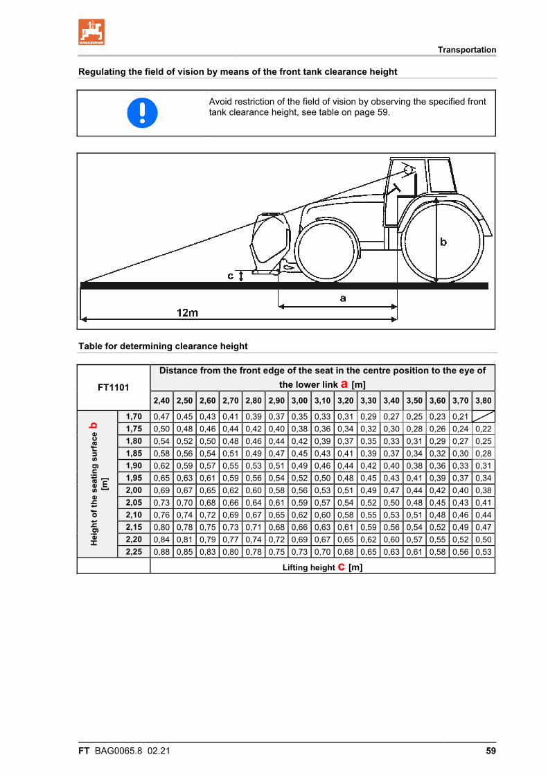
Regulating the field of vision by means of the front tank clearance height
Avoid restriction of the field of vision by observing the specified front tank clearance height, see table on page 59.
Table for determining clearance height
FT1101
Distance from the front edge of the seat in the centre position to the eye of the lower link a [m]
2,40 2,50 2,60 2,70 2,80 2,90 3,00 3,10 3,20 3,30 3,40 3,50 3,60 3,70 3,80
Hei
ght o
f the
sea
ting
surf
ace b
[m
]
1,70 0,47 0,45 0,43 0,41 0,39 0,37 0,35 0,33 0,31 0,29 0,27 0,25 0,23 0,21 1,75 0,50 0,48 0,46 0,44 0,42 0,40 0,38 0,36 0,34 0,32 0,30 0,28 0,26 0,24 0,22 1,80 0,54 0,52 0,50 0,48 0,46 0,44 0,42 0,39 0,37 0,35 0,33 0,31 0,29 0,27 0,25 1,85 0,58 0,56 0,54 0,51 0,49 0,47 0,45 0,43 0,41 0,39 0,37 0,34 0,32 0,30 0,28 1,90 0,62 0,59 0,57 0,55 0,53 0,51 0,49 0,46 0,44 0,42 0,40 0,38 0,36 0,33 0,31 1,95 0,65 0,63 0,61 0,59 0,56 0,54 0,52 0,50 0,48 0,45 0,43 0,41 0,39 0,37 0,34 2,00 0,69 0,67 0,65 0,62 0,60 0,58 0,56 0,53 0,51 0,49 0,47 0,44 0,42 0,40 0,38 2,05 0,73 0,70 0,68 0,66 0,64 0,61 0,59 0,57 0,54 0,52 0,50 0,48 0,45 0,43 0,41 2,10 0,76 0,74 0,72 0,69 0,67 0,65 0,62 0,60 0,58 0,55 0,53 0,51 0,48 0,46 0,44 2,15 0,80 0,78 0,75 0,73 0,71 0,68 0,66 0,63 0,61 0,59 0,56 0,54 0,52 0,49 0,47 2,20 0,84 0,81 0,79 0,77 0,74 0,72 0,69 0,67 0,65 0,62 0,60 0,57 0,55 0,52 0,50 2,25 0,88 0,85 0,83 0,80 0,78 0,75 0,73 0,70 0,68 0,65 0,63 0,61 0,58 0,56 0,53
Lifting height c [m]