Embed Size (px)
Citation preview


OPERATING MANUAL
MPU-1
LEAKAGE CURRENT ALARM SIGNALER
SONEL SA
ul. Wokulskiego 11
58-100 Świdnica, Poland
SONEL TEST & MEASUREMENT Inc.
Santa Clara, Ca, 95054
www.soneltest.com
Version 1.4 9.15.2016
2 OPERATING MANUAL MPU-1 version 1.5
CONTENTS
1 Preface................................................................................................................... 4
2 Introduction .......................................................................................................... 5
3 Safety ..................................................................................................................... 5
4 Description and Features..................................................................................... 5
4.1 Characteristics of MPU-1....................................................................................... 5
4.2 Arrangement of sockets and buttons ...................................................................... 6
4.2.1 Keyboard ....................................................................................................... 6 4.2.2 Sockets ........................................................................................................... 8
4.3 Graphic display (LCD) .......................................................................................... 9
4.4 Acoustic and visual alarm signals. ......................................................................... 9
4.5 Measuring Current with Flexible F-Series Probes. ................................................ 9
5 Starting the operation ........................................................................................ 10
6 Operation ............................................................................................................ 10
6.1 Preparing MPU-1 for operation ........................................................................... 10
6.2 Monitoring the internal power supply voltage supplied by the internal
rechargeable battery ....................................................................................................... 11
6.3 Connecting the device. ......................................................................................... 11
6.4 Operating the interface. ........................................................................................ 12
6.4.1 Monitoring leakage current with “Alarm on” mode ................................... 12 6.4.2 Displaying and Measuring Leakage Current in "Alarm off" mode. ............ 15 6.4.3 Setting the AC current frequency. ............................................................... 16 6.4.5 Info Mode: Activation of the Acoustic Signal. ............................................. 18 6.4.6 Changing the language ............................................................................... 19 6.4.7 Reset function. ............................................................................................. 21
7 Troubleshooting ................................................................................................. 22
7.1 Warnings and information displayed by the device. ............................................ 22
8 Power supply of the device ................................................................................ 23
8.1 Monitoring the power supply voltage .................................................................. 23
8.2 Replacing rechargeable batteries.......................................................................... 23
8.3 Charging rechargeable batteries ........................................................................... 23
8.4 General principles for using Ni-MH rechargeable batteries ................................ 24
9 Cleaning and maintenance ................................................................................ 25

OPERATING MANUAL MPU-1 version 1.5 3
10 Storage ................................................................................................................. 25
11 Dismantling and Disposal .................................................................................. 25
12 Technical specifications ..................................................................................... 25
12.1 Basic data ......................................................................................................... 25
12.2 Other technical specifications .......................................................................... 26
13 Accessories .......................................................................................................... 26
13.1 Basic accessories .............................................................................................. 26
13.2 Optional accessories......................................................................................... 26
14 Manufacturer ...................................................................................................... 28

4 OPERATING MANUAL MPU-1 version 1.5
1 Preface
Thank you for purchasing the MPU-1 leakage current alarm signaler. The MPU-1 is a modern, easy
and safe to use signaling device. Please acquaint yourself with this manual to avoid measuring errors and problems with the operation of the device.
This manual contains three types of warnings. They are presented as a framed text describing the possible risks for the user and the device. Texts starting with word ‘WARNING:’ describe situations,
which may endanger user's life or health when instructions are not followed. Word ‘CAUTION!’ begins
a description of a situation which may result in device damage when instructions are not followed. Indication of possible problems is preceded by word ‘Note:’.
WARNING:
Before operating the device, read thoroughly this manual and observe the safety
regulations and guidelines provided by the manufacturer.
WARNING:
The MPU-1 is designed to provide additional protection against electric shock in the
workplace, therefore using the MPU-1 is NOT a substitute for any other protection measures
in the workplace and/or personal protection equipment used by employees and must not
be relied upon as a sole safety and protection measure. Appropriate occupational health
and safety regulations must be observed along with other instructions, rules and safety
measures in accordance with local or national regulations.
WARNING:
The leakage current alarm signaler is designed to measure and monitor the leakage current
in LV and MV networks. Any application that differs from those specified in this manual may
result in a damage to the device and constitute a source of danger to the user.
WARNING:
The MPU-1 signalers must only be used only by qualified persons, certified to perform
measurements on LV and MV live networks. Operating the device by unauthorized
personnel may result in damage to the device and constitute a source of danger to the user.
WARNING:
Using this manual does not exclude the need to comply with occupational health and safety
regulations and with other relevant fire and safety regulations. Before starting the work with
the device in special environments, e.g. potentially fire-risk/explosive environment, consult
with the person(s) responsible for health and safety. Do not work alone.

OPERATING MANUAL MPU-1 version 1.5 5
2 Introduction
This manual describes the operation of MPU-1 leakage current alarm signaler. We recommend reading
the manual thoroughly in order to avoid errors that may result in danger to the user, or an incorrect
assessment of the tested network. For more information on safety during measurements -see Chapter
3 – Safety. Before first use of the device, be sure to read Chapter 5 – Starting the operation. For
additional information related to interpreting the warnings and information displayed by the device, it is
recommended to read Chapter 7 – Troubleshooting. All information on operating the device may be found in Chapter 6 – Operation.
3 Safety
The MPU-1 is designed for measuring and monitoring the leakage current in LV and MV AC
power systems. It is a tool for assessing the safety of electrical networks by measuring leakage
currents, such as at transmission pylons. The device allows users to set a threshold of leakage
current above which a visual and acoustic alarm will be triggered. The following
recommendations must be observed for the correct operation and accuracy of measured
results:
• Before using the device carefully read this manual
• The MPU-1 should be operated only by qualified persons that have passed occupational health
and safety training.
Do not use or operate the MPU-1 under the following circumstances:
The MPU-1 is damaged, completely, or partially out of order, or has been dropped or subjected to
physical abuse or shock.
The insulation of the test leads are damaged.
The MPU-1 has been stored for an excessive period of time in excessive humidity or heat.
Before using the device make sure the test leads are securely connected to the appropriate measurement sockets.
Repairs may be only performed only by an authorized Sonel service center.
Cautionary Notes:
• If the discharged battery symbol appears on the display (the internal power supply voltage is too low) recharge the batteries.
• When the power supply voltage is too low the measurements performed with the device may
include additional errors undetected by the user and they should not be used to confirm that the tested circuit or network is properly protected.
• Caution is required for AC voltages with RMS value exceeding 30 V or when their peak value
exceeds 42 V. Be also careful when DC voltages exceeding 60 V. Such voltages generate a risk of electric shock.
4 Description and Features
4.1 Characteristics of MPU-1
Design features of the MPU-1 include:
• Constant monitoring of (leakage) current flowing through the grounding of power poles, and pylons, in the range of 0.1 to 299A, in LV and MV 50Hz or 60Hz networks.

6 OPERATING MANUAL MPU-1 version 1.5
• Measurements can be made with one or two current probes. With two probes the measurement of
current is summed for both probes providing the opportunity to measure leakage current in twin poles using individual probes for each component pole.
• An alarm trigger can be set for when the current flow exceeds a user programmable threshold. The
default setting is at 1A. Both an acoustic alarm via a built-in speaker and a visual alarm via flashing
lights are provided.
• No measurement of direct currents.
• Measurements are made with Sonel flexible F-series current probes of Rogowski coil design.
Probes of various diameters can be used without the need to re-calibrate the MPU-1 for each probe.
• The enclosure is ergonomically designed and carries an IP 67 rating. (Protection from ingress
against dust, and immersion to 1m).
• Battery charge status is monitored. An LED indicates operation mode.
4.2 Arrangement of sockets and buttons
Fig.1. Arrangement of LEDs and buttons (front panel).
4.2.1 Keyboard
1 ON/OFF button
Turns the device ON/OFF.
2 MENU button
Selects the measurement function:
• Alarm – setting the alarm on or off
• Curr – setting the alarm threshold for current flow
• Demo – simulation of an alarm condition
1
2
3
4
5
6
OPERATING MANUAL MPU-1 version 1.5 7
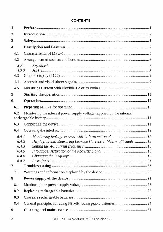
• Freq – sets the rated frequency of the network (50Hz or 60Hz)
• Info – information about the operation of the device
• Lang – selects user interface language • Reset – restores factory (default) settings
3 ENTER button
Enters settings, exits to menu.
4 LED indicating the operational status of the device
• LED Illumination states :
- LED is green – the device is in operational mode
- LED is red – device error (additional error code is displayed, as described below)
- LED flashes red – low battery charge level
• Battery charging mode – when connected to AC charger
- LED flashes green –battery charging
- LED is green – battery is fully charged
5 Buttons
A set of cursors with auto-repetition for choosing MENU options and changing settings
6 Alarm LEDs
A set of red alarm LEDs arranged in two rows on the front panel (5 LEDs in each row), and in two
rows at the sides of the device (5 LEDs on each side). Their operation is described in the next sections.
and

8 OPERATING MANUAL MPU-1 version 1.5
4.2.2 Sockets
CAUTION!
MPU-1 signaler is designed to measure the current flowing through conductors with voltages up to 1000V.
Connecting voltages higher than 25V between any of the test terminals may damage the
device.
7 Measuring socket [Probe (1) / Charger]
To connect a single Sonel F-Series Rogowski-type current probe. Used for measurements with a
single probe. The battery charger also connects to this socket; it has the same pronged connector.
Unused socket should be covered with the flexible socket cover.
8 Measuring [Probe (2)]
To connect a second Sonel F-Series Rogowski-type current probe. Used for measurements with a two probes. Unused socket should be covered with the flexible socket cover.
When using two probes the MPU-1 mathematically sums up the current values from the two probes
and does not take into account any phase shifts.
Fig.2. Arrangement of sockets in MPU - 1.
7 8

OPERATING MANUAL MPU-1 version 1.5 9
4.3 Graphic display (LCD)
Fig.3. Screen view in measurement mode.
4.4 Acoustic and visual alarm signals.
Warning signals:
Continuous two-tone beep with flashing alarm LEDs
• Measured current exceeds the set threshold. The beeping lasts for 30 seconds then becomes muted. If the alarm condition continues it is indicated by flashing alarm LEDs.
Two long beeps with illuminated alarm LEDs, repeated every 15 seconds.
• Indicates a low level of battery charge. The device should be switched off and the batteries should be re-charged. If allowed to continue the MPU-1 will turn off automatically.
Short beeps (with active Info option):
• Indicates when the Info function is turned ON. The signal repeates approx. every 60 seconds.
4.5 Measuring Current with Flexible F-Series Probes.
The MPU-1 is calibrated at the factory with Sonel F-Series probes. Probe models compatible with MPU-1 are listed in Chapter 13 "Accessories".
WARNING:
Dangerous voltages are present. Connecting incompatible or damaged current probes may
cause electric shock. Only use Sonel F-Series probes.
Fig. 2 . Screen view when alarm is off.
Measurement of current
Alarm threshold value
Battery charge status
Operation mode:
Alarm is ON
Measurement of current Battery charge status

10 OPERATING MANUAL MPU-1 version 1.5
Note:
The manufacturer guarantees the measurement accuracy when used with measuring
probes supplied with the device or purchased from manufacturer's authorized supplier.
Using extension cords, non-Sonel supplied probes, or other modifications may be a source
of additional errors and safety hazards.
Note:
"CAT III 1000V" marking on accessories is equivalent to "CAT IV 600V" marking.
5 Starting the operation
Before starting the operation of the device:
• Check the MPU-1 for suitability, do not use if the MPU-1 or test leads are damaged, or is malfunctioning.
• Check the settings of the device; the operating mode, and alarm threshold. Ensure the MPU-1 displays results.
6 Operation
Read this chapter thoroughly as it describes metering circuits, measurement methods, settings and
other important issues.
6.1 Preparing MPU-1 for operation
Before performing measurements:
• Make sure that the battery is fully charged.
• Check the device and accessories for damage
• Check the probes are connected securely and the MPU-1 is adequately situated and protected in the test workplace.
WARNING:
Do not leave the MPU-1 unattended when performing tests.
Do not touch the equipment connected to the tested circuit or network.
Note:
Do not use the MPU-1 if the display is unreadable.
Note:
Using accessories other than those specified by the manufacturer is prohibited and may
result in a danger to the user or damage to the device.

OPERATING MANUAL MPU-1 version 1.5 11
6.2 Monitoring the internal power supply voltage supplied by the
internal rechargeable battery
Ensure the MPU-1 battery is fully charged before use. The charge level of the rechargeable battery is indicated by the battery symbol continuously displayed in the right upper corner of the screen.
Fig. 7. Monitoring the battery charge status
For information on the power supply see: Chapter 8 "Power supply of the device".
6.3 Connecting the device.
CAUTION!
Pay attention to the correct connection of plugs of the clamps, as the accuracy of the
measurements depends on the connection quality. Ensure connections are secure and
making good contact and will provide uninterrupted measurement of current.
CAUTION!
Connecting voltage higher than 25V between any of the test terminals may damage the
device.
Connection of the MPU-1 to the power network or device under test is shown in the drawings below:
Fig.9. Operation with single current probe
Battery charge status
12 OPERATING MANUAL MPU-1 version 1.5
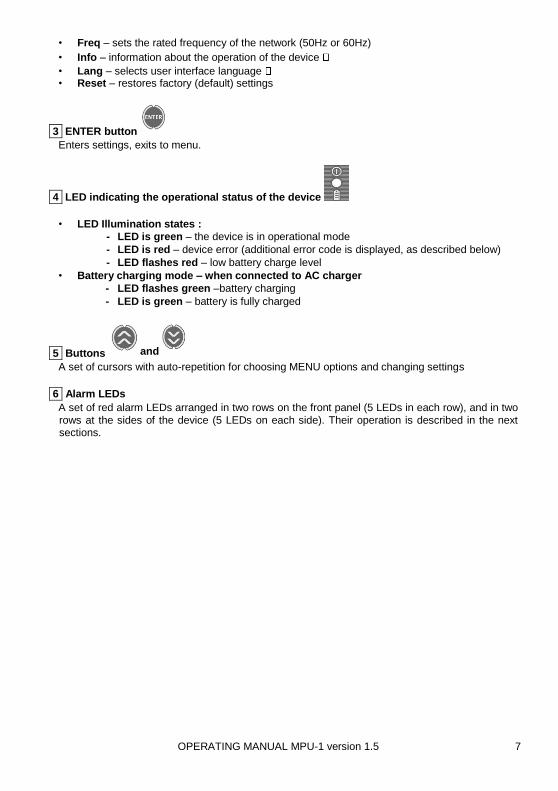
Fig.10. Operation with dual current probes
6.4 Operating the interface.
Additional information:
Pressing MENU button when viewing
the MENU options results in exiting the
current MENU option without
confirming the selected value(s). Its function is equal to BACK /CANCEL
button. Any changes / selected
options are confirmed by pressing ENTER.
6.4.1 Monitoring leakage current with “Alarm on” mode
The usual mode of operation of the MPU-1 is with “Alarm on”. When the MPU-1 is turned on it always
begins in “Alarm on” mode. To monitor leakage current flowing proceed as follows:
Connect current probes to the socket: 7 "Probe (1)" to perform single-probe measurement or to both
sockets "Probe (1)" 7 and "Probe (2)" 8 to perform dual-probe measurement.
Then:

OPERATING MANUAL MPU-1 version 1.5 13
The MPU-1 is in operating mode with alarm on. The top line of the display indicates the measured value
of current. The bottom line alternates with the Alarm mode setting (on or off), changing to displaying
the alarm threshold value in Amps. Depending on the value of the measured current the bottom line
also indicates whether the measured current is: lower (I <), equal (I =) or higher (I>) than the threshold setting.
The MPU-1 measures and monitors AC currents of 50Hz or 60Hz depending on user settings. When
the measured current exceeds the alarm threshold setting both a sound and a visual alarm will be
Press MENU button.
,
Use , butto ns to select Alarm . Confirm your choice by pressing ENTER button.
,
Use , buttons to select Alarm on . Confirm your choice by pressing E NTER button.

14 OPERATING MANUAL MPU-1 version 1.5
triggered. The sound alarm, a beep, lasts for 30 seconds, then is muted. The visual alarm is indicated
by flashing LEDs on the MPU-1.
To set the alarm threshold setting for leakage current:
Press MENU button.
,
Use , buttons to select Current . Confirm your choice by pressing ENTER button.
,
Use , buttons to select the cur- rent value above which the alarm will be triggered. Confirm your choice by pressing ENTER button.
OPERATING MANUAL MPU-1 version 1.5 15
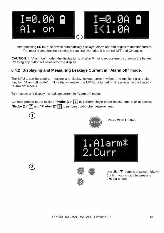
After pressing ENTER the device automatically displays "Alarm on" and begins to monitor current.
The most recent threshold setting is retained even after it is turned OFF and ON again.
CAUTION: In "Alarm on" mode - the display turns off after 5 min to reduce energy drain on the battery.
Pressing any button will re-activate the display.
6.4.2 Displaying and Measuring Leakage Current in "Alarm off" mode.
The MPU-1 can be used to measure and display leakage current without the monitoring and alarm
function; “Alarm off mode”. (Note that whenever the MPU-1 is turned on it is always first activated in
“Alarm on” mode.)
To measure and display the leakage current in “Alarm off” mode:
Connect probes to the socket: "Probe (1)" 7 to perform single-probe measurement; or to sockets
"Probe (1)" 7 and "Probe (2)" 8 to perform dual-probe measurement.
Press MENU button.
,
Use , buttons to select Alarm .
Confirm your choice by pressing ENTER button .

16 OPERATING MANUAL MPU-1 version 1.5
After pressing ENTER the MPU-1 displays “Al. off” (Alarm off). In “Alarm off” mode the MPU-1
displays in real-time the measured AC leakage current at 50Hz / 60Hz depending on user settings but
does not monitor for an alarm condition.
Note:
Pressing MENU button results in exiting the current MENU option without
confirming the selected value(s). Its function is equivalent to BACK/CANCEL.
Remember to press ENTER to confirm a selection.
6.4.3 Setting the AC current frequency.
To set the nominal AC frequency of the network for the equipment being measured as either 50Hz or
60Hz in "Alarm on" mode or in "Alarm off" mode:
Press MENU button.
,
Use , buttons to select Alarm off . Confirm your choice by pressing ENTER button.

OPERATING MANUAL MPU-1 version 1.5 17
After pressing ENTER the MPU-1 displays the measured current in the monitoring/measurement
mode. The last setting of frequency is always saved and retained by the MPU-1 after it is turned OFF
and will be in the last setting state when turned ON again.
6.4.4 DEMO function.
The DEMO function is intended to demonstrate the alarm signal to users and personnel responsible
for electrical safety. After selecting the DEMO function the device enters alarm mode for 5 sec
To start DEMO mode:
,
Use , buttons to select
Frequency. Confirm your choice by
pressing ENTER button
,
Use , buttons to select 50 Hz or 60 Hz . Confirm your choice by pressing ENTER button.

18 OPERATING MANUAL MPU-1 version 1.5
After pressing ENTER the device starts the alarm mode for about 5 seconds, then automatically reverts
to the monitoring/measurement mode that was displayed before entering the DEMO mode.
6.4.5 Info Mode: Activation of the Acoustic Signal.
The Info function enables user to turn on an acoustic-chirp signal that indicates that the device is
activated and operational. The chirp repeats approx. every 60s. Select "On" from Info menu to activate the Info mode. Select "Off" disables this function:
Press MENU button.
Press MENU button.
,
Use , buttons to sel ect Demo . Confirm your choice by pressing ENTER button.

OPERATING MANUAL MPU-1 version 1.5 19
Pressing ENTER automatically reverts the MPU-1 to the monitoring/measurement mode that was
displayed before the user changed the settings of the Info function.
Operation of Info function is interrupted during the charging process and when the user presses the MENU button.
The last setting of Info function is saved and remembered by the device even after it is turned OFF and
ON again.
6.4.6 Changing the language
The Language function is used to change the user language.
,
Use , buttons to select Info . Confirm your choice by pressing ENTER button.
,
Use , buttons to select O n or Off . Confirm your choice by pressing ENTER button.

20 OPERATING MANUAL MPU-1 version 1.5
Press MENU button.
The Last setting of Language function is saved and remembered by the device even after it is turned OFF and ON again.
Note:
Interface language versions may differ from each other, not only by language, but also by
functionality or operational features. After changing the language follow the instructions
for the activated language.
,
Use , buttons to select Lan- guage . Confirm your choice by press- ing ENTER button.
,
Use , buttons to select desired language. Confirm your choice by pressing ENTER button.

OPERATING MANUAL MPU-1 version 1.5 21
6.4.7 Reset function.
The Reset function allows the user to restore factory settings - after using this function the MPU-1:
Resets alarm threshold to 1A
Disables the Info function
The mains network frequency resets to 50Hz
NOTE: The language settings remain unchanged:
After pressing ENTER, the meter will reset and turn off then on again automatically.
Press MENU button.
,
Use , buttons to select Reset . Confirm your choice by pressing ENTER button.
,
Use , buttons to select Yes to reset settings or No to cancel. Confirm your choice by pressing ENTER but- ton.

22 OPERATING MANUAL MPU-1 version 1.5
7 Troubleshooting
7.1 Warnings and information displayed by the device.
The MPU-1 display indicates the following error conditions and warnings - they may be related to the operation of the device or to external conditions affecting the measurement process.
Display
message
Cause Notes Solution
I >299A
Measured current exceeds 299A / message only appears in "Alarm off” mode.
In "Alarm on" mode, the
current exceeding the limit
value will be always
indicated by alarm mode -
in both cases: when the
measuring range of the
meter is exceeded and
when the user-set limit is
exceeded.
Potentially hazardous
situation. Disconnect the
device from the equipment
under test.
Err 310
Temperature of
rechargeable
battery is too low.
Occurs during the battery
charging process.
Stop the charging process.
Move the MPU-1 to a higher
ambient temperature and re-
charge. If the problem persists
contact Sonel’s local service
provider.
Err 311
Temperature of
rechargeable
battery is too
high.
Occurs during the battery
charging process.
Stop the charging process.
Move the MPU-1 to a lower
ambient temperature and re-
charge. If the problem persists
contact Sonel’s local service
provider.
Err 312 Damaged battery Occurs during the battery
charging process.
Contact Sonel’s local service
provider.
Err 313
No charging.
Damaged battery
or a problem with
the power supply
adapter.
Occurs during the battery
charging process.
Check the power supply
connection, if the problem
persists contact Sonel’s local
service provider.
Err 550
Incorrect
calibration
parameters.
The instrument has
detected a loss of
calibration data.
Contact Sonel’s local service
provider
Err XXX Other error. XXX – any other code. Contact Sonel’s local service
provider.

OPERATING MANUAL MPU-1 version 1.5 23
8 Power supply of the device
Note:
MPU-1 is designed to operate only with built-in rechargeable batteries installed in the
factory and with factory accessories for charging them.
CAUTION!
Connecting voltage higher than 25V between any of the test terminals may damage the
device.
8.1 Monitoring the power supply voltage The charge level of the rechargeable battery is indicated by the battery symbol continuously displayed
in the right upper corner of the screen. Ensure the MPU-1 battery is fully charged before use.
Batteries charged.
Batteries low.
Notes:
• A discharged battery appearing on the display along with flashing red status LED indicates that the supply voltage is too low and batteries need to be recharged,
• Extremely low battery charge level is indicated by two long beeps with alarm LEDs flashing, repeated every 15 seconds.
• When Low battery charge level is indicated the device should be switched off, or it will switch off
automatically. Measurements performed with low supply voltage will introduce additional errors.
Consequently, such measurements cannot be relied upon to be correct. Recharge the batteries to remedy.
8.2 Replacing rechargeable batteries
The battery may only be replaced only by Sonel’s authorized service department.
8.3 Charging rechargeable batteries
To charge the batteries connect the AC adapter to the socket marked Clamp (1) / Charger. When the
charging process starts the battery charging symbol appears on the screen and the status LED flashes green.

24 OPERATING MANUAL MPU-1 version 1.5
After 30 seconds the display turns off to save power. It may be re-activated pressing any button. After
the charging process ends the LED status indicator is continuously green and the screen displays "Accu full".
Note:
Due to interferences in the AC power the process of battery charging may finish prematurely. When
charging time is too short, turn the meter off, disconnect the charger and start charging again.
8.4 General principles for using Ni-MH rechargeable batteries
Remove the rechargeable batteries and store them separately if you do not use the device
for a prolonged period of time.
Store the batteries in a dry, cool and well-ventilated place and protect them from direct
sunlight. The storage temperature should not exceed 30°C / 86°F otherwise battery lifetime
will be reduced
Rechargeable batteries Ni-MH usually lasts for 500-1000 charging cycles. The rechargeable
batteries reach their maximum capacity after 2-3 charge and discharge cycles. The most
important factor which influences the lifetime of rechargeable batteries is the level of their
discharge. The deeper the discharge level of the batteries, the shorter their lifetime.
The memory effect is limited in the case of Ni-MH batteries. These batteries may be charged
at any point with no serious consequences. However, it is recommended to discharge them
completely periodically.
During storage of Ni-MH rechargeable batteries they will discharge at the rate of
approximately 30% per month. Keeping rechargeable batteries at high temperatures will
accelerate this process. In order to prevent excessive discharge of rechargeable batteries,
charge them from time to time (even if they are not used). Modern fast chargers detect both
too low and too high temperature of rechargeable batteries. Too low temperature prevents
the process of charging which can damage rechargeable batteries. An increase of the
temperature of the rechargeable batteries will stop charging. Charging at a high ambient
temperature reduces batteries' lifetime and causes a further increase of temperature with the
result that the batteries are not charged to their full capacity.
Note that when the batteries are charged with a fast-charger they are charged only to approx.
80% of their capacity. Better results can be achieved by continuing charging; the charger
enters trickle-charging mode and over a few hours the batteries are charged to their full
capacity.
Charging progress is shown in the battery
symbol.

OPERATING MANUAL MPU-1 version 1.5 25
Do not charge or use rechargeable batteries in extreme temperatures. Extreme temperatures
reduce the lifetime of rechargeable batteries; avoid use in very hot environments. The
working temperature range must be observed: -10°C to +50°C / 14°F to 122°F
9 Cleaning and maintenance
CAUTION!
Use only the maintenance methods specified by the manufacturer in this manual.
The case of the MPU-1 may be cleaned with a soft, damp cloth using all-purpose detergents. Do not
use any solvents or cleaning agents which might scratch or abrade the casing. Current probes should
be cleaned using the same methods as the case. Probes and test leads should be cleaned with water
and detergents, but not immersed, and then dried. The electronic system of the device does not require maintenance.
10 Storage
During the storage of the device, the following recommendations must be observed:
• Disconnect all the test leads from the device
• Thoroughly clean the device and its accessories
• To prevent total discharge of the rechargeable batteries due to the prolonged storage charge them periodically
• Storage temperature conditions must be observed: -20°C to +80°C / -4°F to 176°F
11 Dismantling and Disposal
Scrap and disused electronic equipment must not be placed with waste of another kind and should be
sent to a collection point in accordance with local laws for the disposal of electrical and electronic
equipment. Before the equipment is sent to a collection point, do not dismantle any elements.
Observe local regulations concerning the disposal of equipment, and spent batteries.
12 Technical specifications • The specified accuracy relates to the MPU-1 terminals.
• The abbreviation "m.v." in the specification of measurement uncertainty means a standard measured value.
12.1 Basic data Measuring leakage current with current probes:
Current range Resolution Basic uncertainty
0.1 to 9.9 A 0.1 A ±(5% m.v. + 2 digits)
10 to 299 A 1 A ±(5% m.v. + 2 digits)
• Frequency range: 50Hz or 60Hz.
• Flexible current probes: Sonel F-1
26 OPERATING MANUAL MPU-1 version 1.5
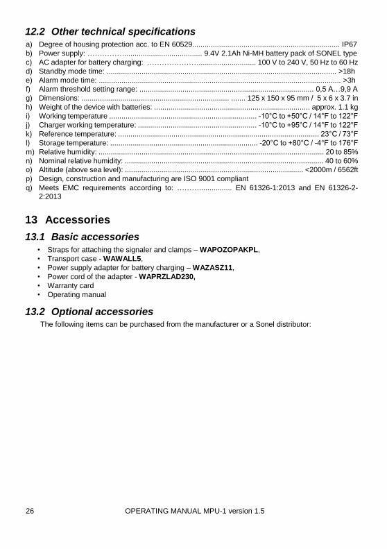
12.2 Other technical specifications a) Degree of housing protection acc. to EN 60529........................................................................ IP67
b) Power supply: ……………...................................... 9.4V 2.1Ah Ni-MH battery pack of SONEL type
c) AC adapter for battery charging: …………………............................ 100 V to 240 V, 50 Hz to 60 Hz
d) Standby mode time: ................................................................................................................ >18h
e) Alarm mode time: ...................................................................................................................... >3h
f) Alarm threshold setting range: ..................................................................................... 0,5 A…9,9 A
g) Dimensions: ........................................................................ ....... 125 x 150 x 95 mm / 5 x 6 x 3.7 in
h) Weight of the device with batteries: ............................................................................ approx. 1.1 kg
i) Working temperature ........................................................................ -10°C to +50°C / 14°F to 122°F
j) Charger working temperature: .......................................................... -10°C to +95°C / 14°F to 122°F
k) Reference temperature: .................................................................................................. 23°C / 73°F
l) Storage temperature: ........................................................................ -20°C to +80°C / -4°F to 176°F
m) Relative humidity: .............................................................................................................. 20 to 85%
n) Nominal relative humidity: ................................................................................................. 40 to 60%
o) Altitude (above sea level): ....................................................................................... <2000m / 6562ft
p) Design, construction and manufacturing are ISO 9001 compliant
q) Meets EMC requirements according to: ………................ EN 61326-1:2013 and EN 61326-2-2:2013
13 Accessories
13.1 Basic accessories
• Straps for attaching the signaler and clamps – WAPOZOPAKPL,
• Transport case - WAWALL5,
• Power supply adapter for battery charging – WAZASZ11,
• Power cord of the adapter - WAPRZLAD230,
• Warranty card
• Operating manual
13.2 Optional accessories The following items can be purchased from the manufacturer or a Sonel distributor:

OPERATING MANUAL MPU-1 version 1.5 27
Note: The color and design of the clamps may vary from the shown image.
F-1 Probe 1000A
Flexible probe F-1 (Rogowski coil) with diameter of 40 cm / circumference of
120 cm; 16 in / 48 in
F-2 Probe 1000A
Flexible probe F-2 (Rog owski coil) with a diameter of 25 cm / circumference of 80 cm;
10 in / 32 in
F-3 Probe 1000A
Flexible probe F-3 (Rogowski coil) with a diameter of 13 cm / circumference of
45 cm; 5 in / 18 in
F-4 Probe 1000A
Flexible probe F4 (Rogowski coil)
circumference / length of 200 cm / 79 in
Charger
Charger for charging the battery from 12V ca r socket.

28 OPERATING MANUAL MPU-1 version 1.5
14 Manufacturer
The manufacturer of the device and provider of service:
Internationally:
SONEL SA
Świdnica, Poland
Tel. +48 74 858 3800
Fax +48 74 858 3809
E-mail: [email protected]
Web page: www.sonel.pl
In the USA:
SONEL TEST & MEASUREMENT Inc.
Santa Clara, CA USA
Tel: (408) 988 1346
Fax: (408) 988 4869
E-mail: [email protected]
Web page: www.soneltest.com
Made in Poland.
Note:
Service repairs must be performed only by Sonel or an authorized Sonel service center.
________________________________________________________________________________ Note: Due to constant product development Sonel S.A. reserves the right to change the design and
specifications without prior notice.