Embed Size (px)
Citation preview

P/N: 83874 (REV. 627-T) September 2016
Before installing hoist, fill in the information below. Antes de instalar el polipasto, rellene los datos siguientes. Enregistrez les informations suivantes avant de faire l'installation.
Rated Load / Carga Nominal / Charge nominale
Serial No. / N° de Serie / No. de Ser.
Purchase Date / Fecha de Compra / Date d'achat
CAPACITIES: 1/8 – 3 TONS (125 – 3000 kg) Follow all instructions and warnings for inspecting, maintaining and operating this hoist.
The use of any hoist presents some risk of personal injury or property damage. That risk is greatly increased if proper instructions and warnings are not followed. Before using this hoist, each operator should become thoroughly familiar with all warnings, instructions and recommendations in this manual. Retain this manual for future reference and use.
Forward this manual to operator. Failure to operate equipment as directed in manual may cause injury.
CAPACIDADES DE CARGA: 1/8 – 3 TONELADAS (125 – 3000 kg) Siga todas las instrucciones y advertencias para inspeccionar, mantener y operar este polipasto.
El uso de cualquier polipasto presenta algunos riesgos de daños a las personas o a las cosas. Este riesgo se ve incrementado si no se siguen correctamente las instrucciones y advertencias. Antes de usar el polipasto el operario debería estar familiarizado con todas las advertencias, instrucciones y recomendaciones de este manual. Guarde este manual para futuras consultas.
Entregue este manual al operario. Si el equipo no se maneja tal y como se recomienda en el presente manual, es posible que se produzcan situaciones de peligro que pueden resultar en daños personales.
CHARGES NOMINALES: 1/8 – 3 TONNES (125 – 3000 kg) Veuillez vous conformer à toutes les instructions et avertissements d'inspection, d'entretien et d'opération de ce palan.
L'utilisation de tout appareil de levage comporte des risques de blessures ou de dégâts matériels. Ces risques sont de beaucoup accrus si les instructions et avertissements ne sont pas suivis. Tours les opérateurs devraient se familiariser complètement avec toutes les recommandations instructions et avertissements de ce manuel avant d'utiliser ce palan. Conservez ce manuel pour utilisation et référence future.
Remettre ce manuel à l'opérateur. L'utilisation de cet équipement contrairement aux directives de ce manuel peut causer des blessures.
ELECTRIC CHAIN HOIST
POLIPASTO ELÉCTRICO DE CADENA
PALAN ÉLECTRIQUE À CHAÎNE
OPERATING, MAINTENANCE & PARTS MANUAL
MANUAL DE FUNCIONAMIENTO, MANTENIMIENTO Y PIEZAS
MANUEL D'ENTRETIEN, D'OPÉRATION ET DE PIÈCES

P/N: 83874 (REV. 627-T) September 2016

1 P/N: 83874 (REV. 627-T) September 2016(ENGLISH)
EN
GLIS
H
CM HOIST PARTS AND SERVICES ARE AVAILABLE IN THE UNITED STATES AND IN CANADA
As a CM Hoist and Trolley user you are assured of reliable repair and parts services through a network of Master Parts Depots and Service Centers that are strategically located in the United States and Canada. These facilities have been selected on the basis of their demonstrated ability to handle all parts and repair requirements promptly and efficiently. To quickly obtain the name of the Master Parts Depot or Service Center located nearest you,
call (800) 888-0985. Fax: (716) 689-5644.
LAS PIEZAS Y REPARACIONES DE LOS POLIPASTOS DE CM ESTÁN ASEGURADAS EN ESTADOS UNIDOS Y CANADÁ
Como usuario de un polipasto y carro de CM le aseguramos cualquier reparación o la disponibilidad de cualquier pieza de repuesto a través de una red de almacenes de piezas de repuesto y centros de servicio situados estratégicamente en Estados Unidos y Canadá. Estas instalaciones se han
seleccionado en base a su capacidad demostrada en la reparación de equipos y suminstro de piezas de repuesto de forma rápida y eficaz. Para obtener la dirección del almacén de piezas de repuesto o del centro de servicio más cercano, llame al teléfono (800) 888-0985. Fax: (716) 689-5644 (sólo en
Estados Unidos y Canadá).
LE SERVICE DE RÉPARATION ET DE PIÈCES POUR PALANS CM EST DISPONIBLE AUX ÉTATS-UNIS ET AU CANADA
Soyez assurés qu'en temps d'utilisateur de palan et treuil CM, d'un service de réparation et de pièces fiable par l'entremise d'un réseau de Centres de service et de Dépôts de pièces maîtresses qui sont stratégiquement situés aux États-Unis et au Canada. Ces établissements ont été sélectionnés sur une base de leur habileté démontrée à s'occuper promptement et efficacement des besoins de réparation de pièces. Composez le (800) 888-0985,
télécopieur : (716) 689-5644 pour obtenir rapidement le nom du dépôt de pièces maîtresses ou du centre de service situé le plus près.

2 P/N: 83874 (REV. 627-T) September 2016(ENGLISH)
EN
GLIS
H
SAFETY PRECAUTIONSEach Lodestar Electric Hoist is built in accordance with the specifications contained herein and at the time of manufacture complied with our interpretation of applicable sections of the *American Society of Mechanical Engineers Code B30.16 “Overhead Hoists,” the National Electrical Code (ANSI/NFPA 70) and the Occupational Safety and Health Act. Since OSHA states the National Electrical Code applies to all electric hoists, installers are required to provide current overload protection and grounding [on the branch circuit section] in keeping with the code. Check each installation for compliance with the application, operation and maintenance sections of these articles.
The safety laws for elevators, lifting of people and for dumbwaiters specify construction details that are not incorporated into the hoists. For such applications, refer to the requirements of applicable state and local codes, and the American National Safety Code for elevators, dumbwaiters, escalators and moving walks (ASME A17.1). Columbus McKinnon Corporation cannot be responsible for applications other than those for which CM equipment is intended.
*Copies of this standard can be obtained from ASME Order Department, 22 Law Drive, Box 2300, Fairfield, NJ 07007-2300, U.S.A.
Improper operation of a hoist can create a potentially hazardous situation which, if not avoided, could result in death or serious injury. To avoid such a potentially hazardous situation, the operator shall:
1. NOT operate a damaged, malfunctioning or unusually performing hoist.
2. NOT operate the hoist until you have thoroughly read and understood this Operating, Maintenance and Parts Manual.
3. NOT operate a hoist which has been modified.
4. NOT lift more than rated load for the hoist.
5. NOT use hoist with twisted, kinked, damaged, or worn load chain.
6. NOT use the hoist to lift, support, or transport people.
7. NOT lift loads over people.
8. NOT operate a hoist unless all persons are and remain clear of the supported load.
9. NOT operate unless load is centered under hoist.
10. NOT attempt to lengthen the load chain or repair damaged load chain.
11. Protect the hoist’s load chain from weld splatter or other damaging contaminants.
12. NOT operate hoist when it is restricted from forming a straight line from hook to hook in the direction of loading.
13. NOT use load chain as a sling, or wrap load chain around load.
14. NOT apply the load to the tip of the hook or to the hook latch.
15. NOT apply the load unless load chain is properly seated in the chain wheel(s) or sprocket(s).
16. NOT apply load if bearing prevents equal loading on all load supporting chains.
17. NOT operate beyond the limits of the load chain travel.
18. NOT leave load supported by the hoist unattended unless specific precautions have been taken.
19. NOT allow the load chain or hook to be used as an electrical or welding ground.
20. NOT allow the load chain or hook to be touched by a live welding electrode.
Improper operation of a hoist can create a potentially hazardous situation which, if not avoided, could result in minor or moderate injury. To avoid such a potentially hazardous situation, the operator shall:
1. Maintain a firm footing or be otherwise secured when operating the hoist.
2. Check brake function by tensioning the hoist prior to each lift operation.
3. Use hook latches. Latches are to retain slings, chains, etc. under slack conditions only.
4. Make sure the hook latches are closed and not supporting any parts of the load.
5. Make sure the load is free to move and will clear all obstructions.
6. Avoid swinging the load or hook.
7. Make sure hook travel is in the same direction as shown on the controls.
8. Inspect the hoist regularly, replace damaged or worn parts, and keep appropriate records of maintenance.
9. Use the hoist manufacturer’s recommended parts when repairing the unit.
10. Lubricate load chain per hoist manufacturer’s recommendations.
11. NOT use the hoist load limiting or warning device to measure load.
12. NOT use limit switches as routine operating stops unless allowed by manufacturer. They are emergency devices only.
13. NOT allow your attention to be diverted from operating the hoist.
14. NOT allow the hoist to be subjected to sharp contact with other hoists, structures, or objects through misuse.
15. NOT adjust or repair the hoist unless qualified to perform such adjustments or repairs.
Usage of hoists that do not involve lifting of the load on the lower hook or using hoists in the inverted position without special precaution may cause an accident resulting in injury and/or property damage.
TO AVOID INJURY:
Consult Columbus McKinnon for information concerning using hoists in these applications.
21. NOT remove or obscure the warnings on the hoist.
22. NOT operate a hoist on which the safety placards or decals are missing or illegible.
23. NOT operate a hoist unless it has been securely attached to a suitable support.
24. NOT operate a hoist unless load slings or other approved single attachments are properly sized and seated in the hook saddle.
25. Take up slack carefully - make sure load is balanced and load holding action is secure before continuing.
26. Shut down a hoist that malfunctions or performs unusually and report such malfunction.
27. Make sure hoist limit switches function properly.
28. Warn personnel of an approaching load.

3 P/N: 83874 (REV. 627-T) September 2016(ENGLISH)
EN
GLIS
H
HOIST SAFETY IS UP TO YOU...
CHOOSE THE RIGHT HOIST FOR THE JOB...Choose a hoist with the capacity for the job. Know the capacities of your hoists and the weight of your loads.
Then match them.
The application, the size and type of load, the attachments to be used and the period of use must also be taken into consideration in selecting the right hoist for the job.
Remember, the hoist was designed to ease our burden and carelessness not only endangers the operator, but in many cases, a valuable load.
INSPECTAll hoists should be visually inspected before use, in addition to regular, periodic maintenance inspections.
Inspect hoists for operations warning notices and legibility.
Deficiencies should be noted and brought to the attention of supervisors. Be sure defective hoists are tagged and taken out of service until repairs are made.
Under no circumstances should you operate a malfunctioning hoist.
Check for gouged, twisted, distorted links and foreign material. Do not operate hoists with twisted, kinked, or damaged chain links.
Load chain should be properly lubricated.
Hooks that are bent, worn, or whose openings are enlarged beyond normal throat opening should not be used. If latch does not engage throat opening of hook, hoist should be taken out of service.
Chains should be checked for deposits of foreign material which may be carried into the hoist mechanism.
Check brake for evidence of slippage under load.
DO NOT LIFT MORE THAN RATED LOAD.
DO OPERATE WITH MANUAL POWER ONLY (ONE OPERATOR)
DO NOT OPERATE DAMAGED OR MALFUNCTIONING HOIST.
DO NOT OPERATE WITH TWISTED, KINKED, OR DAMAGED CHAIN.
DO NOT PULL AT AN ANGLE. BE SURE HOIST AND LOAD ARE IN A STRAIGHT LINE.
DO NOT USE LOAD CHAIN AS A SLING.
USE HOIST PROPERLY
Be sure hoist is solidly held in the uppermost part of the support hook arc.
Be sure hoist and load are in a straight line. Do not pull at an angle.
Be sure load is hooked securely. Do not tip load the hook. Do not load hook latch. Hook latch is to prevent detachment of load under slack chain conditions only.
Do not operate with hoist head resting against any object. Lift the load gently. Do not jerk it.
PRACTICE CAUTION ALWAYSDo not lift co-workers with a hoist.
Make sure everyone is clear of the load when you lift.
Do not remove or obscure operational warning notices.
OPERATOR SERVICECLEANING
Hoists should be kept clean and free of dust, dirt, moisture, etc., which will in any way affect the operation or safety of the equipment.
LUBRICATION
Chain should be properly lubricated.
AFTER REPAIRS
Carefully operate the hoist before returning it to full service.
DO NOT LIFT PEOPLE OR LOADS OVER PEOPLE
VIOLATIONS OF ANY OF THE WARNINGS LISTED MAY RESULT IN SERIOUS PERSONAL INJURY TO THE OPERATOR OR NEARBY PERSONNEL BY NATURE OF RELEASED LOAD OR BROKEN HOIST COMPONENTS.

4 P/N: 83874 (REV. 627-T) September 2016(ENGLISH)
EN
GLIS
H
FOREWORDThis manual contains important information to help you properly install, operate and maintain your hoist for maximum performance, economy and safety.
Please study its contents thoroughly before putting your hoist into operation. By practicing correct operating procedures and by carrying out the recommended preventive maintenance suggestions, you will experience long, dependable and safe service.
After you have completely familiarized yourself with the contents of this manual, we recommend that you carefully file it for future reference.
The information herein is directed to the proper use, care and maintenance of the hoist and does not comprise a handbook on the broad subject of rigging. Rigging can be defined as the process of lifting and moving heavy loads using hoists and other information, we recommended consulting a standard textbook on the subject.
TABLE OF CONTENTS
SAFETY PRECAUTIONSMaster Parts Depots And Service Centers ........................................ 1Safety Precautions ............................................................................. 2Hoist Safety is Up To You ................................................................... 3Foreword ............................................................................................ 4
GENERAL INFORMATIONSpecifications ..................................................................................... 5CM Repair/Replacement Policy ......................................................... 5
ACCESSORIESHook Suspensions ............................................................................. 6Lug Suspensions ................................................................................ 6Series 635 Low Headroom Trolleys .................................................... 6Series 635 Motor Driven Trolleys ........................................................ 6Latchlok Hooks .................................................................................. 7Chain Container .................................................................................. 7
INSTALLATIONUnpacking Information ....................................................................... 7Installing Suspension ......................................................................7-8Attaching Load Chain ......................................................................8-9Installing Series 635 Low Headroom Trolley .................................9-10Power Supply and Electrical Connections ..................................10-11Checking for Twists in Load Chain ................................................... 11Checking for Adequate Voltage at Hoist .....................................11-12Control Cord ..................................................................................... 12
OPERATING INSTRUCTIONSGeneral ............................................................................................. 13Operating Instruction-Hoist .............................................................. 13Hoist with Low Headroom Trolley..................................................... 13Hoist with Motor Driven Trolley ........................................................ 13Safety Procedures ............................................................................ 13
INSPECTIONProcedures ....................................................................................... 14Frequent Inspections ...................................................................14-15Periodic Inspections ....................................................................14-15Preventive Maintenance ................................................................... 14Hook Inspection ............................................................................... 14Load Chain ....................................................................................... 16Protector ........................................................................................... 16
MAINTENANCEHoist Lubrication .............................................................................. 17Trolley Lubrication ............................................................................ 17Exterior Finish ................................................................................... 17Solid State Reverse Switch .............................................................. 17AdjustmentsElectric Brake ................................................................................... 18Limit Switches .............................................................................18-19Troubleshooting ...........................................................................20-21Electrical Data .............................................................................23-24Typical Wiring Diagrams ..............................................................25-47
ASSEMBLY INSTRUCTIONSHook or Lug Suspension .................................................................. 48Weatherproof Hoists ......................................................................... 48Gearing ............................................................................................. 48Fasteners .......................................................................................... 48Lower Hook Block Pin ...................................................................... 48
Removal and Installation of Load Chain......................................48-49Cutting Chains .................................................................................. 50Testing .............................................................................................. 50
REPLACEMENT PARTSOrdering Instructions ........................................................................ 51Parts List and Exploded Views ....................................................52-90Recommended Spare Parts ............................................................. 90
LIST OF TABLESTABLE DESCRIPTION PAGE
1 Lodestar Electric Chain Hoist and Series 635 Trolley Specifications .............................................. 5
2 Recommended Seating Torques for Suspension Adapter Screws ..................................................... 8
3 Series 635 Low Headroom Side Frame Spacing.................................................................. 9
4 Minimum Frequent Inspections .............................................. 15 5 Minimum Periodic Inspections................................................ 15 6 Limit Switches ......................................................................... 19 7 Troubleshooting .................................................................20-21 8 Electrical Data ....................................................................22-23
LIST OF ILLUSTRATIONSFIG. DESCRIPTION PAGE
1 Hook Suspensions .................................................................... 6 2 Lug Suspensions ...................................................................... 6 3 Series 635 Low Headroom Trolley ............................................ 6 4 Series 635 Motor Driven Trolley ................................................ 6 5 Upper or Lower Latchlok Hook ................................................. 7 6 Chain Container ........................................................................ 7 7 Attaching Load Chain ............................................................... 7 8 Contact Block ........................................................................... 8 9 Series 635 Low Headroom Trolley ............................................ 9 10 1/8 To 2 Ton (125kg To 2000 kg)
Hoist To Trolley Assembly ....................................................... 10 11 3 Ton (3000kg) Hoist To Trolley Assembly............................... 10 12 Voltage Conversion Terminal Board ........................................ 10 13 Location of Components ........................................................ 11 14 Hook Inspection ...................................................................... 16 15 Gaging Load Chain ................................................................. 16 16 Limit Switches Models A Thru H-2 ......................................... 18 17 Limit Switches Models J Thru RRT-2 .................................18-19 18 Typical Wiring Diagrams.....................................................24-47 19 Hook Suspensions .................................................................. 48 20 Non-Circular Gearing .............................................................. 48 22 Cutting Chain With A Bolt Cutter ............................................ 50 23 Hoist Frame Componets ....................................................54-55 24 Hoist Upper Suspension Components ..............................56-57 24 Hoist Lower Hook Components ........................................58-59 25 Control End Components ..................................................60-61 26 Brake Components ............................................................62-63 27 Limit Switch Components ..................................................64-65 28 Gearing Components .........................................................66-67 27 Liftwheel Components .......................................................68-69 28 Motor End Components ....................................................70-71 29 Contactor Plate Assemblies...............................................72-84 30 Control Station Components .............................................85-87 28 Trolley Components ...........................................................88-89

5 P/N: 83874 (REV. 627-T) September 2016(ENGLISH)
EN
GLIS
H
GENERAL INFORMATION
SPECIFICATIONSThe Lodestar Electric Chain Hoist is a highly versatile materials handling device that can be used to lift loads that are within rated capacity. The mechanical features of these hoists include an alloy steel lift wheel, Load Protector, hardened steel chain guides, hardened steel gear train, life-time lubrication, forged steel hooks and lightweight aluminum frame. The electrical features include hoist-duty motor, rugged hoist brake, magnetic reversing contactor and voltage conversion board (dual voltage units). The hoist is available with hook or lug suspensions that are supplied separately. Table 1 summarizes the Lodestar Electric Chain Hoist models and the Series 635 Trolleys available. It should be noted that standard single speed hoists are available with 10 (3M), 15 (4.6M) and 20 (6.1M) foot lifts and the standard lift for two speeds hoists is 10 feet. However, hoists with longer lifts are available on a special, per order basis.
CM REPAIR/REPLACEMENT POLICYAll Columbus McKinnon (CM®) Lodestar Electric Chain Hoists are inspected and performance tested prior to shipment. If any properly maintained hoist develops a performance problem due to a material or workmanship defect, as verified by CM®, repair or replacement of the unit will be made to the original purchaser without charge. This repair/replacement policy applies only to Lodestar Hoists installed, maintained and operated as outlined in this manual, and specifically excludes parts subject to normal wear, abuse, improper installation, improper or inadequate maintenance, hostile environmental effects and unauthorized repairs/modifications.
We reserve the right to change materials or design if, in our opinion, such changes will improve our product. Abuse, repair by an unauthorized person, or use of non-CM replacement parts voids the guarantee and could lead to dangerous operation. For full Terms of Sale, see Sales Order Acknowledgement. Also, refer to the back cover for Limitations of Warranties, Remedies and Damages, and Indemnification and Safe Operation.
TABLE 1. SPECIFICATIONSA. Lodestar electric chain hoists
Maximum Capacity Ton (kg)
Model
Lifting Speed Per
Min. Ft. (m)
Motor H.P. (kW)
Shortest Distance
Between Hooks in. (mm)
Net Weight lbs. (kg)
Single Speed 115-1-60
1/8 (125) A 32 (9.8) 1/4 (.19) 14¼ (362) 53 (24)
1/8 (125) AA 60 (18.4) 1/2 (.37) 14¼ (362) 64 (29)
1/4 (250) B 16 (4.9) 1/4 (.19) 14¼ (362) 57 (26)
1/4 ((250g) C 32 (9.8) 1/2 (.37) 14¼ (362) 65 (29.5)
1/2 (500) E 8 (2.4) 1/4 (.19) 17 1/8 (454) 68 (31)
1/2 (500) F 16 (4.9) 1/2 (.37) 14 ¼ (362) 64 (29)
1/2 (500) J 32 (9.8) 1 (.75) 15 9/16 (395) 115 (52.3)
1 (1000) H 8 (2.4) 1/2 (.37) 17 7/8 (454) 75 (34)
1 (1000) L 16 (4.9) 1 (.75) 15 9/16 (395) 117 (53.2)
2 (2000) R 8 (2.4) 1 (.75) 22½ (572) 136 (61.8)
3 (3000) RT 5.5 (1.9) 1 (.75) 25 (635) 161(73.2)
Single Speed 230/460-3-60 or 220/380-3-50 or 220/415-3-50
1/8 (125) A 32 (9.8) 1/4 (.19) 14¼ 67 (30.5)
1/8 (125) AA 60 (18.4) 1/2 (.37) 14¼ 74 (33.6)
1/4 (250) B 16 (4.9) 1/4 (.19) 14¼ 68 (31)
1/4 (250) C 32 (9.8) 1/2 (.37) 14¼ 74 (33.6)
1/2 (500) E 8 (2.4) 1/4 (.19) 17 7/8 79 (36)
1/2 (500) F 16 (4.9) 1/2 (.37) 14¼ 74 (33.6)
1/2 (500) J 32 (9.8) 1 (.75) 15 9/16 113 (51.4)
1/2 (500) JJ 64 (19.6) 2 (1.50) 15 9/16 120 (54.5)
1(1000) H 8 (2.4) 1/2 (.37) 17 7/8 85 (38.6)
1 (1000) L 16 (4.9) 1 (.75) 15 9/16 114 (51.8)
1 (1000) LL 32 (9.8) 2 (1.50) 15 9/16 121 (55)
2 (2000) R 8 (2.4) 1 (.75) 22½ 134 (61)
2 (2000) RR 16 (4.9) 2 (1.50) 22 13/16 136 (61.8)
3 (3000) RT 5.5 (1.9) 1 (.75) 25 161 (73.2)
3 (3000) RRT 11 (3.8) 2 (1.50) 25 161 (73.2)
Maximum Capacity Ton (kg)
ModelLifting Speed
Per Min. Ft. (m)
Motor H.P.
(kW)
Shortest Distance
Between Hooks in. (mm)
Net Weight lbs. (kg)
Two Speed 230-3-60 or 460-3-60 or 220-3-50 or 380-3-50 or 415-3-50
1/8 (125) A-2 10/32 (3.1/9.8) ¼ (.19) 14¼ (362) 69 (31.3)
1/8 (125) AA-2 20/60 (6.1/18.3) ½ (.37) 14¼ (362) 76 (34.5)
**1/4 (250) B-2 5/16 (1.5/4.9) ¼ (.19) 14¼ (362) 70 (31.8)
1/4 (250) C-2 10/32 (3.1/9.8) ½ (.37) 4¼ (362) 176 (34.5)
**1/2 (500) E-2 2.5/8 (.76/2.4) ¼ (.19) 17 7/8 (454) 81 (36.8)
1/2 (500) F-2 5/16 (1.5/4.9) ½ (.37) 14¼ (362) 76 (34.5)
1/2 (500) J-2 10/32 (3.1/9.8) 1 (.75) 15 9/16 (395) 115 (52.3)
1/2 (500) JJ-2 21/64 (6.4/19.5) 2 (1.50) 15 9/16 (395) 125 (56.3)
1 (1000) H-2 2.5/8 (.76/2.4) ½ (.37) 17 7/8 (454) 87 (39.5)
1 (1000) L-2 5/16 (1.5/4.9) 1 (.75) 15 9/16 (395) 116 (52.7)
1 (1000) LL-2 10/32 (3.1/9.8) 2 (1.50) 15 9/16 (395) 126 (57.3)
2 (2000) R-2 2.5/8 (.76/2.4) 1 (.75) 22½ (572) 136 (61.8)
2 (2000) RR-2 5/16 (1.5/4.9) 2 (1.50) 22 13/16 (579) 143 (65)
3 (3000) RT-2 1.75/5.5 (.53/1.68) 1 (.75) 25 (635) 175 (79.5)
3 (3000) RRT-2 3.5/11 (1.1/3.4) 2 (1.50) 25 (635) 177 (80.5)
B. Series 635 Low Headroom Trolleys
Capacity Tons (kg)
For Use with
Models
Adj. for STD S-Beams Depth In. (mm)
Tread Dia. of Wheels In. (mm)
Min. Rad. Curve In.
(mm)
1/8 to 1 (125 to 1000)
A thru LL-2 4 thru 15 (102 thru 381) 3 1/8 (79.4) 24 (609)
2 (2000) R thru RR-2 6 thru 18 (152 thru 457) 4 3/4 (120.6) 24 (609)
3 (3000) RT thru RRT-2 8 thru 15 (203 thru 381) 4 (101.6) 30 (762)
C. Series 635 Motor Driven Trolleys
Capacity Tons (kg)
For Use with
Models
*Travel Speed FPM
(MPM)
Motor H.P.
(kW)
Adj. for STD S-Beams Depth In.
(mm)
Min. Rad. Curve In.
(mm)
1/8 to 2 (125 to 2000)
A thru RR-2 75 (23) ¼ (.19)6 thru 15
(152 thru 381)30 (762)
3 (3000)RT thru RRT-2
75 (23) ¼ (.19)6 thru 15
(152 thru 381)30 (762)
* Lifting and travel speed listed are for 60 Hertz units. For 50 Hertz units, theses speeds will be 5/6 of those listed.
** A 1/2 H.P. (.37 kW) motor furnished on 380-3-50, 415-3-50 and 460-3-60 volt units.

6 P/N: 83874 (REV. 627-T) September 2016(ENGLISH)
EN
GLIS
H
ACCESSORIES
HOOK SUSPENSIONSSwivel and rigid type hook suspensions (see Figure 1) are available for all Lodestar Electric Hoists. However, rigid type hook suspensions are normally recommended for most application. The hook suspensions are intended for suspending the hoist from a trolley which has a single load bar (such as CM’s® Series 632 and 633 Trolleys) or for suspending the hoist from a fixed structure.
Figure 1. Hook Suspensions
LUG SUSPENSIONLug suspensions (see Figure 2) are available for all Lodestar Electric Hoists. These are rigid type suspensions wherein the lug shown replaces the hook (Figure 1) in the suspension adapter. The Lug suspensions are required for suspending the hoist from the Series 635 Low Headroom and Motor Driven Trolleys described next.
Figure 2. Lug Suspensions
Figure 3. Series 635 Low Headroom Trolley
SERIES 635 LOW HEADROOM TROLLEY These are manual push type trolleys (see Figure 3) designed for use with the Lodestar Electric Chain Hoists. A rigid lug suspension (see Figure 2) is required to suspend the hoist from the trolley. The trolley is adjustable for operation on a range of American Standard “S” beams as indicated in Table 1, and it will also operate on flat flanged beams.
Figure 4. Series 635 Motor Driven Trolley
SERIES 635 MOTOR DRIVEN TROLLEY The motor driven trolleys (see Figure 4) are self-contained and supplied complete with independent controls and wiring, including a four directional control station. A rigid lug suspension (see Figure 2) is required to suspend the hoist from the Motor Driven Trolley. The hoist and trolley are joined electrically by connecting the hoist control and power cords (supplied) into the hoist or trolley. The trolley is adjustable for operation on a range of American Standard “S” beams as indicated in Table 1, and it will also operate on flat flanged beams.
7 P/N: 83874 (REV. 627-T) September 2016(ENGLISH)
EN
GLIS
H
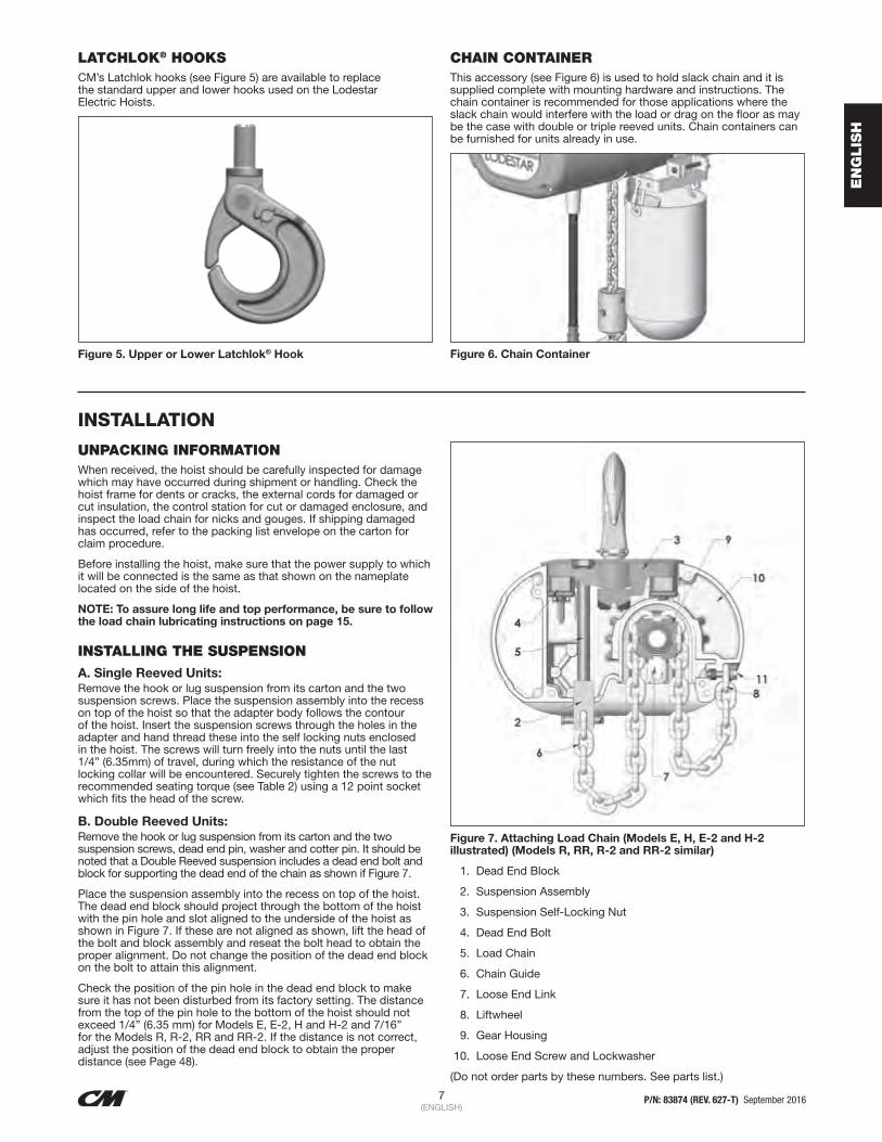
LATCHLOK® HOOKSCM’s Latchlok hooks (see Figure 5) are available to replace the standard upper and lower hooks used on the Lodestar Electric Hoists.
Figure 5. Upper or Lower Latchlok® Hook
CHAIN CONTAINERThis accessory (see Figure 6) is used to hold slack chain and it is supplied complete with mounting hardware and instructions. The chain container is recommended for those applications where the slack chain would interfere with the load or drag on the floor as may be the case with double or triple reeved units. Chain containers can be furnished for units already in use.
Figure 6. Chain Container
INSTALLATION
UNPACKING INFORMATION When received, the hoist should be carefully inspected for damage which may have occurred during shipment or handling. Check the hoist frame for dents or cracks, the external cords for damaged or cut insulation, the control station for cut or damaged enclosure, and inspect the load chain for nicks and gouges. If shipping damaged has occurred, refer to the packing list envelope on the carton for claim procedure.
Before installing the hoist, make sure that the power supply to which it will be connected is the same as that shown on the nameplate located on the side of the hoist.
NOTE: To assure long life and top performance, be sure to follow the load chain lubricating instructions on page 15.
INSTALLING THE SUSPENSION A. Single Reeved Units: Remove the hook or lug suspension from its carton and the two suspension screws. Place the suspension assembly into the recess on top of the hoist so that the adapter body follows the contour of the hoist. Insert the suspension screws through the holes in the adapter and hand thread these into the self locking nuts enclosed in the hoist. The screws will turn freely into the nuts until the last 1/4” (6.35mm) of travel, during which the resistance of the nut locking collar will be encountered. Securely tighten the screws to the recommended seating torque (see Table 2) using a 12 point socket which fits the head of the screw.
B. Double Reeved Units: Remove the hook or lug suspension from its carton and the two suspension screws, dead end pin, washer and cotter pin. It should be noted that a Double Reeved suspension includes a dead end bolt and block for supporting the dead end of the chain as shown if Figure 7.
Place the suspension assembly into the recess on top of the hoist. The dead end block should project through the bottom of the hoist with the pin hole and slot aligned to the underside of the hoist as shown in Figure 7. If these are not aligned as shown, lift the head of the bolt and block assembly and reseat the bolt head to obtain the proper alignment. Do not change the position of the dead end block on the bolt to attain this alignment.
Check the position of the pin hole in the dead end block to make sure it has not been disturbed from its factory setting. The distance from the top of the pin hole to the bottom of the hoist should not exceed 1/4” (6.35 mm) for Models E, E-2, H and H-2 and 7/16” for the Models R, R-2, RR and RR-2. If the distance is not correct, adjust the position of the dead end block to obtain the proper distance (see Page 48).
Figure 7. Attaching Load Chain (Models E, H, E-2 and H-2 illustrated) (Models R, RR, R-2 and RR-2 similar)
1. Dead End Block
2. Suspension Assembly
3. Suspension Self-Locking Nut
4. Dead End Bolt
5. Load Chain
6. Chain Guide
7. Loose End Link
8. Liftwheel
9. Gear Housing
10. Loose End Screw and Lockwasher
(Do not order parts by these numbers. See parts list.)

8 P/N: 83874 (REV. 627-T) September 2016(ENGLISH)
EN
GLIS
H
Now, insert the suspension screws through the holes in the adapter and hand thread these into the self-locking nuts enclosed in the hoist frame. These screws will turn freely into the nut until the last 1/4” (6.35 mm) of travel during which the resistance of the nut locking collar will be encountered. Securely tighten the screws to the recommended seating torque (see Table 2) using a 12 point socket which fits the head of the screw.
To rotate the hook 90°, proceed as follows: NOTE: On the rigid hook suspensions for Models A through RR-2, if it is necessary to rotate the hook 90°, from its factory set position, one of the suspension screws becomes captive and a socket cannot be used to tighten this screw.
1. Using a hammer and drift, drive the pin out of the square hook collar.
2. Remove the square collar from the hook shank.
3. Place a hi-collar type lockwasher (this lockwasher is not supplied with the suspension assembly) under the head of one of the suspension screws. Insert this assembly into the hole in the suspension adapter and rotate the hook 90° to make this screw captive.
4. Re-assemble the square collar to the hook shank using the drive pin previously removed.
5. Follow the instructions above, except tighten the captive screw to the recommended seating torque (see Table 2) using a 12 point box type wrench.
C. Triple Reeved Units: These hoists have a sheave hanger which is loosely connected to the top of the frame by a thin metal plate for shipping purposes. To attach the suspension, support the sheave hanger from the underside of the hoist and remove the nut and seat from the sheave stud. Remove and discard the shipping plate and retain the sheave stud nut and seat since they will be reused later.
Remove the suspension assembly from the carton and the two suspension screws. Place the suspension assembly over the sheave stud and into the recess on top of the hoist.
Insert the suspension screws through the holes in the suspension adapter and hand thread these into the self-locking nut enclosed in the hoist. The screws will turn freely into the nuts until the last 1/4” (6.35 mm) of travel, during which the resistance of the nut locking collar will be encountered. Securely tighten the screws to the recommended seating torque (see Table 2) using a 12 point socket which fits the head of the screw.
After the suspension assembly is installed, secure the sheave stud to the suspension adapter using the round slotted nut and seat that were formerly used to attach the shipping plate to top of the hoist frame. Place the seat over the stud with the flat side down and then rotate the seat so that there is clearance between the seat and the suspension lug or hook. Assemble the nut to the stud and turn the nut by hand until the nut seats in the seat and the sheave hanger is snug in the frame. Then back off the nut until the hole in the stud is in line with one of the slots in the nut. Using a hammer, drive the retaining pin (packed with the suspension assembly) into the hole in the sheave stud until the end of the pin is flush with the edge of the nut.
TABLE 2. RECOMMENDED SEATING TORQUES FOR SUSPENSION ADAPTER SCREWS
Model No's Screw Size Recommended Seating Torque
A thru H-2 3/8”-16 UNC-2A 30 to 45 lb. ft.
J thru RRT-2 1/2”-20 UNF-2A 40 to 80 lb. ft.
Using other than CM supplied high strength suspension screws to attach the suspension adapter to the hoist may cause the screws to break and allow the hoist and load to fall.
TO AVOID INJURY:
Use only the CM supplied suspension screws to attach the suspension to the hoist and torque these screws to the recommended seating torque as specified above.
Also, do not apply any type of lubricant to the threads of these screws. Lubricating the threads will reduce the effort to seat the screws and as a result, tightening the screws to the (Table 2) recommended torque may break the screw, damage the suspension adapter, strip the nuts and/or damage the hoist frame.
ATTACHING LOAD CHAINTo attach the chain to the dead end block on Models E, E-2, H, H-2, R, R-2 and RR-2, proceed as follows:
1. Suspend the hoist from an adequate support.
2. On Models E, E-2, H and H-2, insert the last link of the load chain into the dead end block (2) and secure it with the dead end pin, washer and cotter pin furnished with the suspension.
3. On Models R, R-2, RR and RR-2, slide the contact block up the chain until it is against the bottom of the hoist and the dead end block is projecting through the square opening in the bottom of the block. Insert the last link of the load chain, making sure there are no twists between the hook block and the dead end block, into the dead end block. Push the contact block up slightly and secure the load chain to the dead end block using the dead end pin, washer and cotter pin furnished with the suspension. The dead end pin also supports the contact block (See Figure 8)
Figure 8. Contact Block Used on Models R, R-2, RR and RR-2
INSTALLATION (CONTINUED)

9 P/N: 83874 (REV. 627-T) September 2016(ENGLISH)
EN
GLIS
H
4. Do not remove the plastic ties from the load chain at this time. After the suspension is installed, hoists with a hook suspension can be suspended from its permanent support and then connected to the power supply system (refer to page 8). For hoists with a lug suspension that are to be suspended from a Series 635 Low Headroom Trolley, attach the hoist to the trolley per the following instructions.
INSTALLING THE SERIES 635 LOW HEADROOM TROLLEY (SEE FIGURE 9)
Operating the trolley on a beam that has no rail stops may allow the trolley to fall off the end of beam.
TO AVOID INJURY:
Install rail stops at each end of the beam on which the trolley is to operate.
Figure 9. Series 635 Low Headroom Trolley: 1 and 2 Ton (1000 and 2000kg) Trolley Shown-3 Ton (3000 kg) Similar.
For hoists with a lug suspension that are to be suspended from a Series 635 Motor Driven Trolley, attach the hoist to the trolley, wire the hoist and trolley together and connect the trolley to the power supply system per the instructions supplied with the trolley.
The stops must be positioned so as to not exert impact force on the hoist frame or trolley wheels. They must contact the ends of the trolley side frames.
It is recommended that the trolley be mounted on the beam prior to attaching the hoist to the trolley. Before attempting to mount the trolley on the beam, measure the actual width of the beam flange on which the trolley is to operate. Using the measurement and Table 3, determine the arrangement of the spacer washers. Loosely assemble the side frames, load bracket, spacer washers and nuts on the suspension bolts as shown in Table 3.
If CM’s washer spacing recommendations are not followed, trolley may fall from beam.
TO AVOID INJURY:
Measure the actual beam flange on which the trolley is to operate and use Table 3 to determine the arrangement of the spacer washers for that flange width.
Table 3. Series 635 Low Headroom Trolley Side Frame Spacing
Suspension Bolt
Load Bracket
"X"
A B C D
Suspension Bolt Nuts
Side Frame
FlangeWidth
No. of SpacersA B C D
Standard Load Bracket 3 7/16” Wide – 1 Ton Capacity2 5/8 10 0 0 10
3 9 1 1 93 3/8 8 2 2 83 5/8 7 3 3 7
4 6 4 4 64 5/8 4 6 6 4
5 3 7 7 35 1/4 2 8 8 25 5/8 1 9 9 1
Standard Load Bracket 5 7/16” Wide – 1 Ton Capacity6 6 5 5 5
6 1/4 5 6 6 47 2 9 9 1
Standard Load Bracket 4 3/16” Wide – 2 Ton Capacity3 3/8 8 0 0 83 5/8 7 1 1 7
4 6 2 2 64 5/8 4 4 4 4
5 3 5 5 35 1/4 3 5 6 25 5/8 2 6 7 1
6 0 8 8 0Standard Load Bracket 6 11/16” Wide – 2 Ton Capacity
6 1/4 8 2 1 87 5 5 4 5
7 1/8 5 5 5 47 1/4 4 6 5 57 7/8 2 8 8 1
8 1 9 8 1Standard Load Bracket 4 13/16” Wide – 3 Ton Capacity
4 6 1 1 74 5/8 5 3 3 4
5 4 4 4 35 1/4 3 5 5 25 5/8 3 5 6 1
Standard Load Bracket 3 7/16” Wide – 3 Ton Capacity6 7 2 2 6
6 1/4 6 3 2 67 4 5 5 3
7 1/8 3 6 5 3
*Dimension applies to minimum S-Beam and will vary with larger S-Beams.

10 P/N: 83874 (REV. 627-T) September 2016(ENGLISH)
EN
GLIS
H
Note: Due to the variations in beam flange widths, it is suggested that the beam flange width be measured to determine the exact distribution of spacer washers. The distance between trackwheel flanges (dimension “X”) should be 1/8 to 3/16 inch (3.18 to 4.77 mm) greater than the beam flange width for straight runway beams, and 3/16 to 1/4 inch (4.77 to 6.35 mm) greater than the beam flange width if runway system includes sharp curves. Also, the use of other than CM supplied washers may result in trackwheel to beam flange variations and thus Table 3 will not apply.
On the 1/8 to 2-ton (125 to 2000 kg) trolleys, assemble the suspension lug on hoist to the trolley on beam as shown in Figure 10. The lug is inserted in the trolley load bracket and retained by the vertical load bar pin. A socket head cap screw and lockwasher are used to keep the in in place.
For the 3-ton (3000 kg) trolley, a shackle and pin assembly consisting of a pin retained in a central position by retainers is packed loose with the suspension. Insert this assembly into the opening in the top of the load bracket with the legs of the shackle down. Position the shackle pin in the groove provided for the same in the load bracket making sure it is centered between the suspension bolts.
Now install the trolley on the beam by sliding one side frame out far enough to allow all the trackwheels to clear the beam flange. Lift the trolley up so that the trackwheels are riding on the beam, draw the side frames together and tighten the nuts snugly. Insert the cotter pins through the slotted nuts and holes in the suspension bolts and spread the legs of the cotter pins to secure.
On the 3 ton (3000 kg) trolley (refer to Figure 11), drive one retaining pin into the hole on one end of the lug pin. Raise the hoist into position so that the lug is between the legs of the shackle. Align the holes in the shackle and lug. Insert the lug pin in the aligned holes and secure the lug pin by driving the remaining retaining pin into the hole in the lug pin. Make certain that the shackle pin is properly seating in the load bracket by manipulating the hoist and checking for freedom of movement (swinging) in both planes and all four directions.
NOTE: The shackle pin should be retained and centered in the shackle by the retainers.
Figure 10. 1/8 to 2 Ton (125 to 2000 kg) Hoist to Trolley Assembly
Figure 11. 3 Ton (3000 kg) Hoist to Trolley Assembly
NOTE: After the unit is connected to the power supply system (see below), suspend a capacity load from the hoist and operate the trolley over the entire length of the runway or monorail system to be sure that the adjustments and operation is satisfactory. On systems with curves, the edges of the rail at the curved sections should be kept lightly lubricates with grease.
An excessively worn beam flange may fail and allow the trolley to fall from the beam.
TO AVOID INJURY:
Periodically inspect the beam flange for wear. Replace beam if flange is worn.
POWER SUPPLY AND ELECTRICAL CONNECTIONS The hoist should be connected to a branch circuit which complies with the requirements of the National Electrical Code and applicable local codes.
It is recommended, especially for a single phase hoist with a one horsepower (.75 kW) motor, that a line of adequate capacity be run directly from the power supply to the hoist to prevent having problems with low voltage and circuit overloads.
For grounding of the hoist, the power cord includes a grounding conductor (green wire). Furthermore, the suspension system on which the hoist is mounted must also be permanently grounded.
Before connecting the hoist to the power supply, check that the power to be used agrees with that shown on the hoist identification plate. In addition, for a three phase, dual voltage unit, check the voltage shown on the tag attached to the power cord.
Figure 12. Voltage Conversion Board
INSTALLATION (CONTINUED)

11 P/N: 83874 (REV. 627-T) September 2016(ENGLISH)
EN
GLIS
H
NOTE: Before connecting the hoist to the power supply, check that the power to be used agrees with the position of voltage change plug on the voltage change board.
The nominal hoist voltage rating corresponding to the voltage range given on the hoist identification plate is:
Single Speed Units Two Speed Units
Range Nominal Volts Range Nominal Volts
110-120 115 208-230 230
208-240 230 440-460 460
440-480 460
THREE PHASE HOISTUnless ordered on a special basis, all single speed dual voltage (230/460-3-60, 220/230-3-50 and 220/415-3-50) hoists are factory set to operate on 460-3-60 (380-3-50 or 415-3- 50). However, a voltage conversion board is provided to easily and quickly change from 460 to 230 (or 380 to 220 or 415 to 220) volt operation. The voltage conversion board shown in Figure 12 is located in the hoist as shown in Figure 13.
Figure 13. Location of Components
Voltage conversion board is located under frame cover (1) for Models A thru H and under motor housing cover (2) for Models J thru RRT.
Limit switches and electric brake are located under frame cover (1) for all hoists.
PROPER PHASING Since the motor in a three phase hoist can rotate in either direction, depending on the manner in which it is connected to the power supply, the direction of hook movement must be checked during the original installation and each time hoist is moved to a new location.
Note: Serious damage can result if the hook is run to the upper or lower limit of travel with the hook operating in a direction opposite to that indicated by the control station.
Therefore, proceed as follows:
1. 1. Make temporary connections at the power supply.
2. Operate (UP) control in control station momentarily. If hook raises, connections are correct and can be made permanent.
3. If hook lowers, it is necessary to change direction by interchanging the Red lead and the Black lead of hoist power cord at power supply. Under no circumstances should the internal wiring of control station or hoist be changed to reverse hook direction. The wiring is inspected and tested before leaving the factory.
Allowing the hook block to run into the bottom of the hoist when raising a load or allowing the chain to become taut between the loose end screw and the frame when lowering a load may break the chain and allow the load to drop.
TO AVOID INJURY:
Do not allow the hook block to contact the bottom of the hoist or the loose end chain to become taut.
Also, do not force the Lodestar Protector to compensate for improperly adjusted limit switches or reverse voltage phasing.
CHECKING FOR TWIST IN LOAD CHAIN MODELS E, H, E-2,H-2, R, RR, R-2 AND RR-2 The best way to check for this condition is to run the lower hook, without a load, up to within 24 inches (609 mm) of hoist. If the dead end of the chain has been properly installed, a twist can occur only if the lower hook block has been capsized between the strands of chain. Reverse capsize to remove twist.
MODELS RT, RT-2, RRT AND RRT-2 On these models, the load chain is dead ended on top of the lower hook block. If the chain has been properly installed, the only way a twist can occur is if the lower hook block has been capsized between the strands of chain. If this has occurred, two strands of chain will be wrapped around each other and to remove this, reverse the capsize.
CHECKING FOR ADEQUATE VOLTAGE AT HOIST The hoist must be supplied with adequate electrical power in order to operate properly. For proper operation, the voltage, (measured at the end of the standard 15 foot (4.6 m) power cord with the hoist operating in the , up direction with full load) must be as indicated in the table below.
Nominal Current Minimum Running Voltage
Minimum Starting Voltage
115-1-60 104 98
230-1-60 207 196
230-3-60 187 –
460-3-60 396 –
220-3-50 198 –
380-3-50 365 –
415-3-50 399 –

12 P/N: 83874 (REV. 627-T) September 2016(ENGLISH)
EN
GLIS
H
Signs of inadequate electrical power (low voltage) are: • Noisy hoist operations due to brake and/or contactor chattering.
• Dimming of lights or slowing of motors connected to the same circuit.
• Heating of the hoist motor and other internal components as well as heating of the wires and connectors in the circuit feeding the hoists.
• Failure of the hoist to lift the load due to motor stalling.
• Blowing of fuses or tripping of circuit breakers.
To avoid these low voltage problems, the hoist must be connected to an electrical power supply system that complies with the National Electrical Code and applicable local codes. This system must also be rated for a minimum of 20 amps and it must have #14 AWG (2.0 mm) or larger wiring, a disconnecting means, overcurrent protection (slow blow fuses or inverse-time circuit breakers) and provisions for grounding the hoist.
Failure to properly ground the hoist presents the danger of electric shock.
TO AVOID INJURY:
Permanently ground the hoist as instructed in this Manual.
Low voltage can also be caused by using an undersized extension cord to supply power to the hoist. The following chart should be used to determine the size wires in the extension cord in order to minimize the voltage drop between the power source and the hoist.
Length of Extension CordSingle Phase Hoist Three Phase Hoist
Minimum Wire Size Minimum Wire Size
Up to 50 Feet (15.2 M)
#14 AWG(1.6 mm)
#16 AWG(1.3 mm)
80 FEET(24.1 M)
#12 AWG(2.0 mm)
#16 AWG(1.3 mm)
120 FEET(36.7 M)
#10 AWG(2.6 mm)
#14 AWG(1.6 mm)
Failure to provide a proper supply system for the hoist may cause hoist damage and offers the potential for a fire.
TO AVOID INJURY:
Provide the hoist with a 20 amp, minimum, overcurrent protected power supply system per the national Electrical Code and applicable local codes as instructed in this Manual.
Remember, operation with low voltage can void the CM repair/replacement policy. When in doubt about any of the electrical requirements, consult a qualified electrician.
Always disconnect the power from the power supply system and lockout/tagout disconnecting means before before servicing the hoist.
Working in or near exposed energized electrical equipment presents the danger of electric shock.
TO AVOID INJURY:
Disconnect power and lockout/tagout disconnecting means before removing cover or servicing this equipment.
CHECKING LIMIT SWITCH OPERATIONOperate hoist over the entire length of its rated lift, checking upper and lower limit switches for correct operation as follows:
• Press (UP) control and raise the lower hook until top of hook block is about one foot below the hoist.
• Cautiously continue raising the hook until the upper limit switch stops the upward motion. The upper limit switch is set at the factory to stop the hook block 3 inches (76.2 mm) from bottom of the hoist on all units with standard 10 foot ( 3 M) lift except Models AA and AA-2. Factory setting is 6 inches (152.4 mm) for these models and for all other models equipped with chain for lifts longer than 10 feet(3 M).
• If adjustment is necessary, see page 17.
Allowing the hook block to run into the bottom of the hoist when raising a load or allowing the chain to become taut between the loose end screw and the frame when lowering the load may break the chain and allow the load to drop.
TO AVOID INJURY:
Do not allow the hook block to contact the bottom of the hoist or the loose end chain to become taut.
• Press (DOWN) control and cautiously lower hook until lower limit switch stops the downward motion. From 7 to 11 chain links (depending on hoist model) should be between the loose end link and the hoist entry. See Figures 7 and 8.
• If adjustment is necessary, see pages 16-17. NOTE: If the hoist is equipped with a chain container reset the upper and lower limit switches as indicated on page 17. Set the upper limit switch so that the uppermost point of hook travel is just below the bottom of the chain container. Set the lower limit switch so that there is a minimum of ten links showing below the bottom if the hoist when the hook is at its lowest position. Under no condition should the hook block or load be permitted to come in contact with the chain container. If contact is made, the function of the chain container can be interfered with and its fasteners imperiled.
CONTROL CORD Unless ordered on a special basis, the hoist is supplied with a control cord that will position the control station approximately 4 feet above the lower hook when it is at the lower limit of the lift. If this places the control station too close to the floor, a “control cord alteration kit” (Key No. 627-474, Part Number 28642) can be obtained from CM for shortening the length of the control cord.
Tying knots or loops to shorten the drop of the control station will make the strain relief ineffective and the internal conductors of the cord may break.
TO AVOID INJURY:
Shorten the control cord using the control cord alteration kit and the instructions provided with the kit.
INSTALLATION (CONTINUED)

13 P/N: 83874 (REV. 627-T) September 2016(ENGLISH)
EN
GLIS
H
OPERATING INSTRUCTIONS
GENERAL4. The Protector™ is designed to allow the intermediate gear to
slip on an excessive overload. An overload is indicated when the hoist will not raise the load. Also, some clutching noise may be heard if the hoist is loaded beyond rated capacity. Should this occur, immediately release the pup control to stop the operation of the hoist. At this point, the load should be reduced to the rated hoist capacity or the hoist should be replaced with one of the proper capacity. When the excessive load is removed, normal hoist operation is automatically restored.
CAUTION: The Protector™ is susceptible to overheating and wear when slipped for extended periods. Under no circumstance should the clutch be allowed to slip for more than a few seconds.
Due to the above, a hoist equipped with a Protector™ is not recommended for use in any application where there is a possibility of adding to an already suspended load to the point of overload. This includes dumbwaiter (*see below) installations, containers that are loaded im mid-air, etc.
(*)Refer to limitations on Page i concerning dumbwaiter applications.
Also, if a Lodestar Hoist with a Protector™ is used at unusual extremes of ambient temperatures, above 150°F. (106° C.)or below 15°F. (-0° C.), changes in lubricant properties may permit the hoist to raise larger loads than under normal operating conditions and present possibility of damage or injury.
5. All hoists are equipped with an adjustable screw limit switch, which automatically stops the hook at any predetermined point when either hoisting or lowering.
6. The control station used on two speed hoists is similar to single speed unit, except that either of two definite speeds may be selected by the operator in both hoisting and lowering. Each control when partially depressed provide SLOW speed and when fully depressed gives FAST speed. Partial release of control returns hoist to slow speed, while complete release allows hoist to stop. Rated lifting speeds are shown on hoist identification plate. SLOW speed is intended as a means of carefully controlling or “spotting” the load, although the hoist may be operated solely at this speed if desired. It is not necessary to operate in the SLOW speed position as the hoist will pick up a capacity load at FAST speed from a standing start. In other words, it is not necessary to hesitate at the slow position when moving control from STOP to FAST position or vice versa.
7. If material being handled must be immersed in water, pickling baths, any liquid, dusty or loose solids, use a sling chain of ample length so that the hook is always above the surface. Bearings in the hook block are shielded only against ordinary atmospheric conditions.
HOIST 1. Before picking up a load, check to see that the hoist is directly
overhead.
2. WHEN APPLYING A LOAD, IT SHOULD BE DIRECTLY UNDER HOIST OR TROLLEY. AVOID OFF CENTER LOADING OF ANY KIND.
3. Take up a slack load chain carefully and start load easily to avoid shock and jerking of hoist load chain. If there is any evidence of overloading, immediately lower the load and remove the excess load.
4. DO NOT allow the load to swing or twist while hoisting.
5. DO NOT allow the load to bear against the hook latch.
HOIST WITH LOW HEADROOM TROLLEY This unit should be moved by pushing on the suspended load or by pulling the empty hook. However, the unit can also be moved by pulling on the control station since an internal steel cable extends the length of the control cord and is anchored to the hoist and to the control station.
HOIST WITH MOTOR DRIVEN TROLLEYThis unit should be moved by operating the controls marked u(Forward) and t(Reverse) in control station. Unless altered by the erector, depressing u(Forward) control will move the hoist toward motor housing end. Anticipate the stopping point and allow trolley to coast to a smooth stop. Reversing or “plugging” to stop trolley causes overheating of motor and swaying of load.
SAFETY PROCEDURES 1. For safety precautions and a list of DO’S and DO NOT’S for
safe operation of hoists, refer to page ii.
2. When preparing to lift a load, be sure that the attachments to the hook are firmly seated in hook saddle. Avoid off center loading of any kind, especially loading on the point of hook.
3. When lifting, raise the load only enough to clear the floor or support and check to be sure that the attachments to the hook and load are firmly seated. Continue to lift only after you are assured the load is free of all obstructions.
4. DO NOT load hoist beyond the rated capacity shown on hoist identification plate or on the hoist motor housing cover or hoist back frame cover. Overload can cause immediate failure of some load-carrying part or create a defect causing subsequent failure at less than rated capacity. When in doubt, use the next larger capacity of CM Lodestar Hoist.
5. DO NOT use this or any other overhead materials handling equipment for lifting persons.
6. Stand clear of all loads and avoid moving a load over the heads of other personnel. Warn personnel of your intention to move a load in their area.
7. DO NOT leave the load suspended in the air unattended.
8. Permit only qualified personnel to operate unit.
9. DO NOT wrap the load chain around the load and hook onto itself as a choker chain. Doing this will result in:
a. The loss of the swivel effect of the hook which could mean a twisted chain and a jammed lift wheel.
b. The upper limit switch is by-passed and the load could hit the hoist
c. The chain could be damaged at the hook.
10. On two and three part reeved hoists, check for twists in the load chain. A twist can occur if the lower hook block has been capsized between the strands of chain. Reverse the capsize to remove twist.
11. DO NOT allow the load to bear against the hook latch. The latch is to help maintain the hook in position while the chain is slack before taking up slack chain.
Allowing the load to bear against the hook latch and/or hook tip can result in loss of load.
TO AVOID INJURY:
Do not allow the load to bear against the hook latch and/or hook tip. Apply load to hook bowl or saddle only.
12. Take up a slack load chain carefully and start load easily to avoid shock and jerking of hoist load chain. If there is any evidence of overloading, immediately lower the load and remove the excess load.
13. Do not allow the load to swing or twist while hoisting.
14. Never operate the hoist when flammable materials or vapors are present. Electrical devices produce arcs or sparks that can cause a fire or explosion.
15. STAY ALERT! Watch what you are doing and use common sense. Do not use the hoist when you are tired, distracted or under the influence of drugs, alcohol or medication causing diminished control.

14 P/N: 83874 (REV. 627-T) September 2016(ENGLISH)
EN
GLIS
H
INSPECTION
PROCEDURESTo maintain continuous and satisfactory operation, a regular inspection procedure must be initiated to replace worn or damaged parts before they become unsafe. Inspection intervals must be determined by the individual application and are based on the type of service to which the hoist will be subjected and the degree of exposure to wear, deterioration or malfunction of the critical components.
The type of service which the hoist is subjected can be classified as “NORMAL,” “HEAVY,” “SEVERE.”
NORMAL SERVICEInvolves operation with randomly distributed loads within the rated load limit, or uniform loads less than 65 percent of rated load for not more than 25 percent of the time.
HEAVY SERVICEInvolves operating the hoist within the rated load limit which exceeds normal service.
SEVERE SERVICEIs normal or heavy service with abnormal operating conditions.
Two classes of inspection, FREQUENT and PERIODIC, must be performed.
FREQUENT INSPECTIONSThese inspections are visual examinations by the operator or other designated personnel. Records of such inspections are not required. The frequent inspections are to be performed monthly for normal service, weekly to monthly for heavy service, and daily to weekly for severe service, and they should include those items listed in Table 4.
PERIODIC INSPECTIONSThese inspections are visual inspections of external conditions by an appointed person. Records of periodic inspections are to be kept for continuing evaluation of the condition of the hoist. Periodic inspections are to be performed yearly for normal service, semi-annually for heavy service and quarterly for severe service, and they are to include those items listed in Table 5.
Any deficiencies are to be corrected before the hoist is returned to service. Also, the external conditions may show the need for disassembly to permit a more detailed inspection, which, in turn, may require the use of non-destructive type testing.
PREVENTIVE MAINTENANCEIn addition to the above inspection procedure, a preventive maintenance program should be established to prolong the useful life of the hoist and maintain its reliability and continued safe use. The program should include periodic and frequent inspections with particular attention being paid to the lubrication of the various components using the recommended lubricants (see page 15).
HOOK INSPECTION Hooks damaged from chemicals, deformations or cracks, or that have more than a 10° twist from the hook’s unbent plane or excessive opening or seat wear must be replaced. Also, hooks that are opened and allow the latch to not engage the tip, must be replaced. Any hook that is twisted or has excessive throat opening indicates abuse or overloading of the unit. Inspect other load sustaining parts for damage.
On latch type hooks, check to make sure that the latch is not damaged or bent and that it operates properly with sufficient spring pressure to keep the latch tightly against the tip of the hook and allow the latch to spring back to the tip when released. If the latch does not operate properly, it should be replaced. See Figure 14 to determine when the hook must be replaced.

15 P/N: 83874 (REV. 627-T) September 2016(ENGLISH)
EN
GLIS
H
Table 4 Minimum Frequency Inspections
Minimum Frequency Inspections
Type of ServiceItem
Normal Heavy Severe
Monthly Weekly to Monthly Daily to Weekly
a) Brake for evidence of slippage.
b) Control functions for proper operation.
c) Hooks for damage, cracks, twists, excessive throat opening, latch engagement and latch operation – see page 12.
d) Load chain for adequate lubrication, as well as for signs of wear, damaged links or foreign matter – see page 14.
e) Load chain for proper reeving and twists.
Table 5 Minimum Periodic Inspections
Minimum Periodic Inspections
Type of ServiceItem
Normal Heavy Severe
Yearly Every Six Months Every Three Months
a) All items listed in Table 4 for frequent inspections.
b) External evidence of loose screws, bolts or nuts.
c) External evidence of worn, corroded, cracked or distorted hook block, suspension screws, gears, bearings and dead end block and chain pin.
d) External evidence of damage to hook retaining nut and pin. Also check the upper suspension adapter making sure it is fully seated in the hoist frame and that both screws are tight.
e) External evidence of damage or excessive wear of the liftwheel and hook block sheave chain pockets. Widening and deepening of the pockets may cause the chain to lift-up in the pocket and result in binding between liftwheel and chain guides or between the sheave and hook block. Also, check the chain guides for wear or burring where the chain enters the hoist. Severely worn or damaged parts should be replaced.
f) External evidence of excessive wear or brake parts and brake adjustment – see page 16. v
g) External evidence of pitting or any deterioration of contactor contacts. Check the operation of the control station making sure the buttons operate freely and do not stick in either position.
h) Inspect the electrical cords and cables and control station enclosure for damaged insulation.
i) Inspect trolley trackwheels for external wear on tread and flange, and for wear on internal bearings surfaces as evidenced by a looseness on the stud. Suspension components for damage, cracks, wear and operation. Also check suspension adapter screws for proper tightness-(see page 5).
j) Inspect the loose end link, loose end screw and dead end block on double reeved units. Replace worn or distorted parts.
k) Inspect the suspension lug or hook for excess free play or rotation. Replace worn parts as evidenced by excess free play or rotation.
l) Inspect for signs of lubricant leaks at the gasket between the gear housing and back frame. Tighten screws holding back frame to gear housing. If leak persists, repack housing and gears with grease and install a new gasket.
m) On the Models RT, RT-2, RRT and RRT-2:
1. Inspect shackle and lug pins for wear. Replace if worn.
2. Check dead end screw in lower hook block for wear and tightness.* Replace if worn.
3. Check shackle pin for proper seating in groove of load bracket.
4. Inspect cloverleaf plate on bottom of sheave hanger for wear or burring. Replace if worn.
5. Inspect sheave stud nut and seat for wear. Replace if worn or damaged.
*When tightening the special, dead end socket head screw, it should be held firmly in place and torqued from the nut end only to avoid damage to the screw and/or dead end chain link (Refer to step J on page 49).To measure opening, depress latch against hook body as shown.

16 P/N: 83874 (REV. 627-T) September 2016(ENGLISH)
EN
GLIS
H
INSPECTION (CONTINTUED)
Figure 14a. LATCH TYPE HOOK (Upper and Lower)
Models Replace Hooks When Opening is Greater Than
A, A-2, AA, AA-2, B, B-2, C, C-2, F AND F-2
1 3/16 (30.2 mm)
E, E-2, H, H-2, J, J-2, JJ, JJ-2, L, L-2, LL AND LL-2
1 5/16 (33.3mm)
R, R-2, RR AND RR-2, RT, RT-2, RRT AND RRT-2
1 1/2 (38.1 mm)
Figure 14b. LATCHLOCK® TYPE HOOK (UPPER AND LOWER)
ModelsReplace Hook When Opening or Sear are:
"A" Max. "B" Max.
A, A-2, AA, AA-2, B, B-2, C, C-2, E, E-2, F, F-2, H, H-2, J, J-2, JJ, JJ-2,
L, L-2, LL, LL-21 31/64 in. 21/32 in.
R, R-2, RR, RR-2 1 59/64 in. 27/32 in.
RT, RT-2, RRT AND RRT-2 2 1/2 in 1 1/8 in
LOAD CHAINClean and Inspection First clean the load chain with a non-acid or non-caustic type solvent. Then slack the chain and make a link-by-link inspection for nicks, gouges, twisted links and excessive wear or stretching. Chain should be gaged throughout its entire length and replaced if worn beyond serviceable limits.
Gaging Load Chain Wear To determine if load chain should be continued in service, check gage lengths as indicated in Figure 15. Chain worn beyond length indicated, nicked, gouged or twisted should be replaced before returning hoist to service. Chain should be clean, free of twists and pulled taut before measuring.
To aid in gaging load chain wear. A chain gage can be obtained from CM. This can be obtained by ordering chain gage Part No. 3191.
Note that worn chain can be an indication of worn hoist components. For this reason, the hoist’s chain guides, hook blocks and liftwheel should be examined for wear and replaced as necessary when replacing worn chain.
Also, these chains are specially heat treated and hardened and should never be repaired.
Figure 15. Gaging Load Chain Wear
Models Dia. of Chain Stock
No. of Links to Gage
Max. Gage Length Allowable Used
CHain
A thru HA-2 thru H-2
0.250”(6.35mm)
1914 13/16(376 mm)
J thru RRTJ-2 thru RRT-2
0.312(7.9mm)
2118 7/8
(479 mm)
Using other than CM supplied load chain may cause the chain to jam in the hoist and/or allow the chain to break and the load to drop.
TO AVOID INJURY:
Due to size requirements and physical properties, use only CM HoistAloy load chain in the Lodestar Hoists.
IMPORTANT: Do not use replaced chain for other purposes such as lifting or pulling. Load chain may break suddenly without visual deformation. For this reason, cut worn chain into short lengths to prevent use after disposal.
PROTECTOR The Protector should operate for the normal life of the hoist without service. The device has been lubricated and calibrated at the factory for a specific model of Lodestar Hoist and is not to adjustable or interchangeable with other models. For proper overload protection, be sure before installing a Protector that it is correct for the unit. The edge of the spring washer of the Protector has been color coded at the factory as follows:
Models Protector Color Code
A, A-2 White
AA, AA-2 Light Blue
B, B-2, E, E-2 White
C, C-2 Orange
F, F-2, H, H-2 Orange
J, J-2 Red
JJ, JJ-2 White-Green
L, L-2, RT, RT-2 Green
LL, LL-2 Yellow
R, R-2 Green
RR, RR-2, RRT, RRT-2 Yellow
Removing the snap ring on the Protector assembly will allow the parts to spring apart.
TO AVOID INJURY:
Do not attempt to disassemble the Protector.

17 P/N: 83874 (REV. 627-T) September 2016(ENGLISH)
EN
GLIS
H
MAINTENANCE
The lubricants used in and recommended for the Lodestar Hoist may contain hazardous materials that mandate specific handling and disposal procedures.
TO AVOID CONTACT AND CONTAMINATION:
Handle and dispose of lubricants only as directed in applicable material safety data sheets and in accordance with applicable local, state and federal regulations.
HOIST LUBRICATION NOTE: To assure extra long life and top performance, be sure to lubricate the various parts of the Lodestar Hoist using the lubricants specified below. If desired, these lubricants may be purchased from CM. Refer to page 52 for information on ordering the lubricants.
• The Protector™ should operate for the normal life of the hoist without service. The device has been lubricated and calibrated at the factory for a specific model of Lodestar Hoist and is not adjustable or interchangeable with other models.
CAUTION: The Protector™ is to be used with Century Lubricants HB-11, #3 grease. Use of any other grease will damage Protector™ parts or cause improper operation.
The gears and Protector™ (627-327 and 627-328) are packed at assembly with grease and should not need to be renewed unless the gears have been removed from the housing and degreased.
CAUTION: Never degrease or attempt to disassemble the Protector™. Degreasing may damage parts or cause erratic, inconsistent operation. If the Protector™ has been degreased, it must be replaced by a factory calibrated device.
If the gears are removed from the housing, wipe the excess grease off the outside Protector™ surfaces with a soft cloth and degrease the remaining gears and housings. Upon reassembly, add 7 oz. of above grease to gears and housing. Also, coat the spline on the end of the drive shaft (627-311) with a molydisulphide lubricant such as “Super Herculon.”
For Models JJ, LL, RR, RRT, JJ-2, LL-2, RR-2 and RRT-2, see page 48 for special gearing alignment instructions.
• The limit switch gears are of molded nylon and require no lubrication.
• Apply a light film of machine oil to the limit switch shaft threads (627-220 pages 64 and 65) at least once a year.
• On Models RT, RT-2, RRT and RRT-2 suspended from trolleys, the upper sheave, shackle pin and lug pin must be periodically lubricated with Lubriplate Bar and Chain Oil 10-R (Fiske Bros. Refining Co.). Also, apply a light film of EP Grease (Acheson Colloids Co. Molydag #204, or equal) to the spherical surfaces of the sheave stud nut and the sheave stud nut seat.
Bearings • All bearings and bushings except the lower hook thrust bearing are
prelubricated and require no lubrication. Lubricate the lower hook thrust bearing at least once a month, using a heavy cup grease.
Chain Guides, Liftwheel & Lower Sheave Wheel• When the hoist is disassembled for inspection and/or repair, the
chain guides, lower sheave wheel (on double chain units) and liftwheel must be lubricated with Lubriplate, Bar and Chain Oil 10-R (Fiske Bros. Refining Co.) prior to reassembly. Apply sufficient lubricant to obtain run-off and full coverage.
Load Chain A small amount of lubricant will greatly increase the life of load chain. Do not allow the chain to run dry.
Keep it clean and lubricate at regular intervals with Lubriplate, Bar and Chain Oil 10-R (Fiske Bros. Refining Co.) or equal lubricant. Normally, weekly lubrication and cleaning is satisfactory, but under hot and dirty conditions, it may be necessary to clean the chain at least once a day and lubricate it several times between cleanings.
When lubricating the chain, apply sufficient lubricant to obtain natural run-off and full coverage.
Used motor oils contain known carcinogenic materials.
TO AVOID INJURY:
Never use motor oils as a chain lubricant. Only use Lubriplate Bar and Chain Oil 10-R as a lubricant for the load chain.
TROLLEY LUBRICATION Low Headroom Trolley• CM trackwheel bearings are pre-lubricated and require no
lubrication.
EXTERIOR FINISH The exterior surfaces of the hoist and trolleys have a durable, scratch resistant baked powder coating. Normally, the exterior surfaces can be cleaned by wiping with a cloth. However, if the finish is damaged, compatible touch-up paint can be purchased from CM. Refer to page 52 for information on ordering the paint.
SOLID STATE REVERSE SWITCH (115-1-60/230-1-60 Units Only) Above an ambient temperature of 104°F. (40° C.), the frequency of hoist operation should be limited to avoid overheating the solid state reverse switch. Even at temperatures less than 104° F. (40° C.), high duty cycle, frequent starting or reversing, excessive inching, jogging or plugging may overheat the solid state reverse switch. Overheating the switch will cause it to malfunction, and this in turn will overheat the motor and/or damage the solid state reverse switch.
If allowed to cool, the solid state will return to normal operation. However, before returning the hoist to service, the following procedure should be used to determine if the switch has been damaged.
1. De-energize the power system supplying the hoist and remove the solid state reverse switch.
2. Connect the solid state reverse switch to a 115-1-60/230-1-60 light circuit as shown below.
3. Close the switch to energize the 115-1-60/230-1-60 power supply. The light bulb will illuminate if the solid state reverse switch is not damaged. If the bulb fails to illuminate, the switch is damaged and must be replaced.
4. Turn the 115-1-60/230-1-60 power off and remove the solid state reverse switch from the test circuit.
Reinstall the solid state reverse switch in the hoist and reconnect it using the wiring diagram supplied with the hoist. Re-energize the power system supplying the hoist and test for proper operation. Also, ventilate the space around the hoist and/or reduced duty cycle, excessive starting, excessive plugging to reduce future malfunctions of the solid state reverse due to overheating.

18 P/N: 83874 (REV. 627-T) September 2016(ENGLISH)
EN
GLIS
H
ADJUSTMENTSELECTRIC BRAKE ASSEMBLYThe correct air gap between armature and field, when brake is not energized, is 0.025 inch (.635 mm) and need not be adjusted until the gap reaches 0.045 inches (1.14 mm). When checking brake gap, always reset to 0.025 inch (.0635 mm).
To adjust the brake, proceed as follows:
1. Disconnect hoist from power supply.
2. Remove back frame cover, see Figure 13.
3. Before adjusting the gap:
a. back off the stud nuts and examine friction linings and friction surfaces for excessive wear, (min. thickness .188 inches (4.78 mm)), scoring or warpage.
b. Check shading coils to be sure they are in place and not broken. A missing or broken shading coil will cause the brake to be noisy when hoist is operated. Any of these symptoms indicate the need for replacement of parts.
4. Turn adjusting nuts clockwise gaging the air gap at both ends.
5. Replace cover, reconnect the power and check operation.
LIMIT SWITCHES If limit switch operation has been checked as described on page 10 and is not operating correctly or is not automatically stopping the hook at a desired position, proceed as follows:
1. Disconnect hoist from power supply.
2. Remove back cover, see Figure 13.
3. The position of upper and lower limit switches are indicated on the fiber insulator.
4. Loosen the screws to permit guide plate to be moved out of engagement with the traveling nuts, refer to Figures 16 and 17. For Rotatable Limit Switch, slightly pull out on the guide spring, disengaging the the travel nut, refer to figure 16A and 17A.
1
234
5
Figure 16. Limit Switches, Models A thru H-2
1. Limit Switch Sub-Assembly
2. Limit Switch Shaft
3. Traveling Nuts
4. Guide Plate
5. Screws
Figure 16a. Rotatable Limit Switch, Models A thru H-2
15
3
2
4
Figure 17. Limit Switches, Models J thru RRT-2
1. Limit Switch Sub-Assembly
2. Limit Switch Shaft
3. Traveling Nuts
4. Guide Plate
5. Screws
MAINTENANCE (CONTINTUED)

19 P/N: 83874 (REV. 627-T) September 2016(ENGLISH)
EN
GLIS
H
Figure 17a. Rotatable Limit Switch, Models J thru RRT-2
SETTING UPPER LIMIT SWITCH1. Refer to Table 6-The “A” dimensions given are the minimum
distances that should be set between top of hook block and bottom of hoist. In other words, the highest allowable hook position.
CAUTION: the “A” dimensions shown in the table are the minimum allowed for safe operation and should not be reduced.
2. Reconnect hoist to power supply.
3. Run hook to the desired upper position, cautiously operating the hoist without a load.
4. Disconnect hoist from power supply.
5. Moving one traveling nut toward the other increasing hook travel and away from the other decreases the travel. Now, turn the nut nearest the switch indicated as the “UPPER LIMIT SWITCH” until it just breaks the limit switch contacts. An audible click will be heard as the switch opens. Continue to rotate the nut toward the switch an additional one full tooth.
6. Reposition the guide plate in the next slot and securely tighten screws.
7. Reconnect hoist to power supply and check the stopping point of hook by first lowering the hook about 10 inches, then raise the hook by jogging cautiously until the upper limit switch stops upward motion. The stopping point of hook should be the desired upper position. If not, repeat the above instructions.
8. Double check the setting by lowering the hook about 24 inches (609 mm) and then run the hook into the upper limit with p(UP) control held depressed.
9. Fine adjustment of the upper limit setting may be obtained by inverting the guide plate in Step 10. The offset on the plate gives adjustments equivalent to 1/2 notch, see Table 6 for the Hook Travel Per Notch of Limit Switch Nut.” When inverting the plate, it may be necessary to use the notch adjacent to the one used in the preliminary setting.
SETTING LOWER LIMIT SWITCH 1. Refer to Table 6-The “B” dimensions given are the minimum
number of load chain links that should be set between the loose end link and the hoist frame on the loose end side of the chain. In other words, the lowest allowable hook position.
CAUTION: the “B” dimensions shown in the table are the minimum allowed for safe operation and should not be reduced.
2. Reconnect hoist to power supply.
3. Run the hook to the desired lower position, cautiously operating the hoist without a load.
4. Disconnect hoist from power supply.
5. Moving one traveling nut toward the other increases hook travel and away from the other decreases the travel. Now, turn the nut nearest the switch indicated as the “LOWER LIMIT SWITCH” until it just breaks the limit switch contacts. An audible click will be heard as the switch opens. Continue to rotate the nut toward the switch an additional one full tooth.
6. Reposition the guide plate in the next slot and securely tighten screws.
7. Reconnect hoist to power supply, and check the stopping point of the hook by first raising the hook about 10 inches, then lower the hook by jogging cautiously until the lower limit switch stops the downward motion. The stopping point of hook should be the desired lower position. If not, repeat the above instructions.
8. Double check setting by raising the hook about 24 inches (609.6 mm) and the run the hook into the lower limit with the q(DOWN) control held depressed.
9. Fine adjustment of the lower limit setting may be obtained by inverting the guide plate in Step 10. The offset on the plate gives adjustments equivalent to 1/2 notch, see Table 6 for the “Hook Travel Per Notch of Limit Switch Nut”. When inverting the plate, it may be necessary to use the notch adjacent to the one used in the preliminary setting.
Table 6. Limit Switches
Hook Travel Per Notch of Limit Switch Nut (44TPI)
Max Lengeth of Lift
Hook Travel Per Notch A in. (mm) B (links)
Model ft. (M) in. (mm) Min. Min.
A, A-2, C, C-2 204 (62.2) 1-5/16 (33.3) 1-1/2 (38.1) 6
AA, AA-2 385 (117.3) 2-1/2 (63.5) 2 (30.8) 6
B, B-2, F, F-2 102 (31.1) 11/16 (17.5) 1-1/2 (38.1) 6
E, E-2, H, H-2 47 (14.3) 11/32 (93.1) 1-3/4 (44.5) 6
J, J-2, L, L-2 125 (38.1) 3/4 (19.0) 1-1/2 (38.1) 8
JJ, JJ-2 254 (77.4) 1-15/32 (37.3) 2-1/2 (63.5) 8
LL, LL-2 254 (77.4) 1-15/32 (37.3) 1-1/2 (38.1) 8
R, R-2 66 (20.1) 3/8 (9.5) 2-1/2 (63.5) 8
RR, RR-2 125 (38.1) 3/4 (19.0) 2-1/2 (63.5) 8
RT, RT-2 44 (13.4) 1/4 (6.35) 2-1/2 (63.5) 8
RRT, RRT-2 83 (25.3) 15/32 (11.9) 2-1/2 (63.5) 8
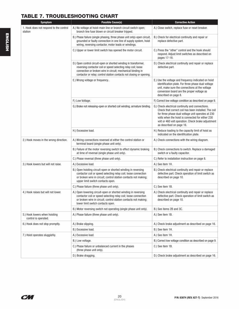
20 P/N: 83874 (REV. 627-T) September 2016(ENGLISH)
EN
GLIS
H
TABLE 7. TROUBLESHOOTING CHARTSymptom Possible Cause(s) Corrective Action
1. Hook does not respond to the control station
A.) No voltage at hoist-main line or branch circuit switch open; branch line fuse blown or circuit breaker tripped.
A.) Close switch, replace fuse or reset breaker.
B.) Phase failure (single phasing, three phase unit only)-open circuit, grounded or faulty connection in one line of supply system, hoist wiring, reversing contactor, motor leads or windings.
B.) Check for electrical continuity and repair or replace defective part.
C.) Upper or lower limit switch has opened the motor circuit. C.) Press the “other” control and the hook should respond. Adjust limit switches as described on pages 17-18.
D.) Open control circuit-open or shorted winding in transformer, reversing contactor coil or speed selecting relay coil; loose connection or broken wire in circuit; mechanical binding in contactor or relay; control station contacts not closing or opening.
D.) Check electrical continuity and repair or replace defective part.
E.) Wrong voltage or frequency.. E.) Use the voltage and frequency indicated on hoist identification plate. For three phase dual voltage unit, make sure the connections at the voltage conversion board are the proper voltage as described on page 8.
F.) Low Voltage. F.) Correct low voltage condition as described on page 9.
G.) Brake not releasing-open or shorted coil winding; armature binding. G.) Check electrical continuity and connections. Check that correct coil has been installed. The coil for three phase dual voltage unit operates at 230 volts when the hoist is connected for either 230 volt or 460 volt operation. Check brake adjustment as described on page 16.
H.) Excessive load. H.) Reduce loading to the capacity limit of hoist as indicated on the identification plate.
2.) Hook moves in the wrong direction. A.) Wiring connections reversed at either the control station or terminal board (single phase unit only).
A.) Check connections with the wiring diagram.
B.) Failure of the motor reversing switch to effect dynamic braking at time of reversal (single phase unit only).
B.) Check connections to switch. Replace a damaged switch or a faulty capacitor.
C.) Phase reversal (three phase unit only). C.) Refer to installation instruction on page 8.
3.) Hook lowers but will not raise. A.) Excessive load. A.) See item 1H.
B.) Open hoisting circuit-open or shorted winding in reversing contactor coil or speed selecting relay coil; loose connection or broken wire in circuit; control station contacts not making; upper limit switch contacts open.
B.) Check electrical continuity and repair or replace defective part. Check operation of limit switch as described on page 10.
C.) Phase failure (three phase unit only). C.) See item 1B.
4.) Hook raises but will not lower. A.) Open lowering circuit-open or shorted winding in reversing contactor coil or speed selecting relay coil; loose connection or broken wire in circuit; control station contacts not making; lower limit switch contacts open.
A.) Check electrical continuity and repair or replace defective part. Check operation of limit switch as described on page 10.
B.) Motor reversing switch not operating (single phase unit only). B.) See items 2B and 3C.
5.) Hook lowers when hoisting control is operated.
A.) Phase failure (three phase unit only). A.) See item 1B.
6.) Hook does not stop promptly. A.) Brake slipping. A.) Check brake adjustment as described on page 16.
B.) Excessive load. B.) See item 1H.
7.) Hoist operates sluggishly. A.) Excessive load. A.) See item 1H.
B.) Low voltage. B.) Correct low voltage condition as described on page 9.
C.) Phase failure or unbalanced current in the phases (three phase unit only).
C.) See item 1B.
D.) Brake dragging. D.) Check brake adjustment as described on page 16.

21 P/N: 83874 (REV. 627-T) September 2016(ENGLISH)
EN
GLIS
H
Symptom Possible Cause(s) Corrective Action
8.) Motor overheats A.) Excessive load. A.) See item 1H.
B.) Low voltage. B.) Correct low voltage condition as described on page 9.
C.) Extreme external heating. C.) Above an ambient temperature of 40°C. (104°F.), the frequency of hoist operation must be limited to avoid overheating of motor. Special provisions should be made to ventilate the space or shield the hoist from radiation.
D.) Frequent starting or reversing. D.) Avoid excessive inching, jogging or plugging. This type of operation drastically shortens the motor and contactor life and causes excessive brake wear.
E.) Phase failure or unbalanced current in the phase (three phase unit only).
E.) See item 1B.
F.) Brake dragging. F.) Check brake adjustment as described on page 16.
G.) 115-1-60 Units: Solid state reverse switch exposed to excessive temperature or the switch is damaged.
G.) See page 15.
9.) Hook fails to stop at either or both ends of travel.
A.) Limit switches not opening circuits. A.) Check switch connections, electrical continuity and mechanical operation. Check the switch adjustment as described on pages 16 & 17. Check for a pinched wire.
B.) Shaft not rotating. B.) Check for damaged gears.
C.) Traveling nuts not moving along shaft guide plate loose; shaft or nut threads damaged.
C.) Tighten guide plate screws. Replace damaged part.
10.) Hook stopping point varies. A.) Limit switch not holding adjustment. A.) See item 9.
B.) Brake not holding. B.) Check the brake adjustment as described on page 16.
TWO SPEED HOIST
11.) Hoist will not operate at slow speed in either direction.
A.) Open Circuit. A.) Open or shorted motor winding, loose or broken wire in circuit, speed selecting contactor stuck in opposite speed mode. Replace motor, repair wire and/or replace speed selecting contactor.
B.) Phase Failure. B.) See item 1B.
12.) Hoist will not operate at fast speed in either direction.
A.) Open Circuit. A.) See Item 11A.
B.) Open speed selecting circuit. B.) Open or shorted winding in speed selecting contactor coil. Loose connection or broken wire in circuit. Mechanical binding in contactor. Control station contacts not making or opening. Replace speed selector; repair connection, replace contactor or control station.
C.) Phase Failure. C.) See Item 1B.
13.) Hook will not raise at slow speed. A.) Excessive load. A.) See item 1H.
B.) Phase Failure. B.) See Item 1B.
C.) Open Circuit. C.) See item 11A.
D.) Brake not releasing. D.) See Item 1G.
14.) Hook will not lower at slow speed. A.) Phase Failure. A.) See item 1B.
B.) Open Circuit. B.) See item 11A.
C.) Brake not releasing. C.) See Item 1G.
15.) Hook will not raise at fast speed. A.) Excessive load. A.) See item 1H.
B.) Phase Failure. B.) See Item 1B.
C.) Brake not releasing. C.) See Item 1G.
16.) Hook will not lower at fast speed. A.) Phase Failure. A.) See Item 1B.
B.) Brake not releasing. B.) See Item 1G.
17.) Hook moves in proper direction at one speedwrong direction at other speed.
A.) Phase reversal. A.) Wiring reconnected improperly. Interchange two leads of motor winding that is out
TABLE 7. TROUBLESHOOTING CHART (CONTINUED)

22 P/N: 83874 (REV. 627-T) September 2016(ENGLISH)
EN
GLIS
H
ELECTRICAL DATA
TO DETECT OPEN AND SHORT CIRCUITS IN ELECTRICAL COMPONENTS.Open circuits in the coils of electrical components may be detected by isolating the coil and checking for continuity with an ohmmeter or with the unit in series with a light or bell circuit. Shorted turns are indicated by a current draw substantially above normal (connect ammeter in series with suspected element and impose normal voltage) or D.C. resistance substantially below normal. The current method is recommended for coils with very low D.C. resistance. Motor current draw in the stator should be measured with the rotor in place and running. Brake, relay and contactor coil current should be measured with the core iron in operating position.
Table 8. Electrical Data for Hoist Components
Transformer Voltage Leads *D.C. Resistance (OHMS)
230/460 to 115
X2 to X1 27.9
H2 to H1 99.0
H3 to H4 111.8
230/380 to 48
X2 to X1 5.2
H2 to H1 99.0
H3 to H4 112.6
220/415 to 24
X2 to X1 1.3
H2 to H1 100.4
H3 to H4 114.9
575 to 115X2 to X1 28.4
H4 to H1 329.1
Models Contactor Or
Speed SelectorCoil Voltage
NominalCurrent(Amps)
*D.C.Resistance
(OHMS)
A thru H-2
115 0.04 297.5
48 0.09 56.3
24 0.19 14.9
JJ thru RRT-2
115 0.07 126.6
48 0.17 25.1
24 0.33 6.4
Models Contactor Or
Speed SelectorCoil Voltage
NominalCurrent(Amps)
*D.C.Resistance
(OHMS)
A, AA, B, C, E, F and H
115 .51 5.8
A thru H-2 **230 .17 23.1
A-2 thru H-2 460 .20 92.3
A, A-2, AA, AA-2, B, B-2, C, C-2, E, E-2,
F, F-2, H, H-2 575 .14 140.0
J, L, R, RT 115 1.25 1.1
J, J-2, L, L-2, LL-2, R, R-2, RT, RT-2
**230 .46 4.6
JJ, JJ-2, LL, LL-2, RR, RR-2, RRT,
RRT-2**230 1.7 2.2
J-2, L-2, R-2, RT-2 460 .25 18.7
JJ-2, LL-2, RR-2, RRT-2
460 1.5 8.9
J, J-2, L, L-2, LL-2, R, R-2, RT, RT-2
575 .50 38.5
JJ, JJ-2, LL, LL-2, RR, RR-2, RRT,
RRT-2575 1.70 14.2
* Resistance values listed are nominal and they may vary slightly from component to component.
** On dual voltage units (230/460-3-60, 220/380-3-50 and 220/415-3-50), brake coils operate on 230 (220) volts.

23 P/N: 83874 (REV. 627-T) September 2016(ENGLISH)
EN
GLIS
H
TABLE 8. ELECTRICAL DATA (CONTINUED)
Models Volts- Phase-Hertz H.P. (kW)
Full Load Current (Amps)
Leads*D.C.
Resistance (OHMS)
A,B,E 115-1-60 1/4 (.19) 4.6T1 to T2 (run)
1.9T3 to T4 (run)T5 to T8 (start) 3.6
A,B,E 230-1-60 1/4 (.19) 2.3T1 to T2 (run)
4.3T3 to T4 (run)T5 to T8 (start) 4.9
A,B,E
230/460-3-60
1/4 (.19)
1.4/.7W-B to O-BL
14.8W-B to O-B
220/380-3-50 1.4/.7W to O-G
Y-B to Y-BL29.5
220/415-3-50 1.4/.7Y-B to Y-GY-BL to Y-G
575-3-60 .5 W-BL to W-B98.2
550-3-50 .6 W-B to P
A-2, B-2, E-2
230-3-60
.08/.25 (.06/.19)
1.7/1.8W-B to W
17.5W-B to W-BL W to W-BL
220-3-50 1.9/2.0Y-BL to Y-B
42.5Y-G to Y-BLY-G to Y-B
A-2, AA-2. B, C,
C-2, E-2, F-2, H-2
230-3-60
.15/.5 (.12/.37)
1.8/2.0W-B to W
13.5W-B to W-BL W to W-BL
220-3-50 2.1/2.4Y-BL to Y-B
25.0Y-G to Y-BL Y-G to Y-B
460-3-60 1.0/1.0W-B to W
63.0W-B to W-BL
380-3-50 1.2/1.2W to W-BLY-BL to Y-B
104415-3-50 1.2/1.2
Y-G to Y-BLY-G to Y-B
575-3-60 .8/.85W-B to W
99.1W-B to W-BL
550-3-50 .8/.90Y-BL to Y-B
156.0Y-G to Y-B
AA, C, F, H
115-1-60 1/2 (.37) 7.2T1 to T2 (run)
1.9T3 to T4 (run)T5 to T8 (start) 3.6
AA, C, F, H
230-1-60 1/2 (.37) 3.6T1 to T2 (run)
1.9T3 to T4 (run) T5 to T8 (start) 3.6
AA, C, F, H
230/460-3-60
1/2 (.37)
1.8/.09W-B to O-BL
7.8W-B to O-B
230/380-3-50 2.1/1.0W to O-G
Y-B to Y-BL15.6
220/415-3-50 2.1/1.0Y-B to Y-GY-BL to Y-G
575-3-60 .8 W-BL to W-B48.3
575-3-50 .91 W-B to P
J,L, R,RT
115-1-60 1 (.75) 9.8T1 to T2 (run)
1.1 T3 to T4 (run)T5 to T8 (start) 1.3
J,L, R,RT
230-1-60 1 (.75) 4.9T1 to T2 (run)
1.1 T3 to T4 (run)T5 to T8 (start) 1.3
Models Volts- Phase-Hertz H.P. (kW)
Full Load Current (Amps)
Leads*D.C.
Resistance (OHMS)
J,L, R,RT
230/460-3-60
1 (.75)
3.0/1.5 W-B to W-BL
4.7W-BL to W-B
220/380-3-50 3.6/1.8 W to W-B
Y-BL to Y-B9.4
220/415-3-50 3.6/1.8 Y-G to Y-BLY-G to Y-B
575-3-60 1.5W to W-B
29.6W to W-BL W-B to W-BL
J-2, L-2, R-2,
RT-2
230-3-60
.33/1 (.25/.75)
3.4/5.0Y-B to Y-BL
19.4Y-B to Y-G Y-BL to Y-G
220-3-50 3.2/4.7W-B to W-BL
7.7W-B to WW-BL to W
J-2, L-2, R-2,
RT-2
460-3-60
.33/1 (.25/.75)
1.5/2.4 Y-B to Y-BL
80.8Y-B to Y-G
380-3-50 1.6/2.4 Y-BL to Y-G
W-B to W-BL29.4
415-3-50 1.6/2.4 W-B to WW-BL to W
J-2, L-2, R-2,
RT-2
575-3-60
.33/1 (.25/.75)
1.1/1.9Y-B to Y-BL
125.6Y-B to Y-G Y-BL to Y-G
550-3-50 1.3/2.1W-B to W-BL
45.4W-B to W W-BL to W
JJ, LL, RR, RRT
230/460-3-60
2 (1.50)
5.8/2.9 W-B to W-BL
2.2W-BL to W-B
220/380-3-50 3.4/3.3W to W-B
Y-BL to Y-B9.4
220/415-3-50 3.4/3.3Y-G to Y-BLY-G to Y-B
575-3-60 3.2W to W-B
14.8W to W-BL W-B to W-BL
JJ-2, LL-2, RR-2, RRT-2
230-3-60
.67/2 (.50/1.50)
5.8/8.8Y-B to Y-BL
14.1Y-B to Y-GY-BL to Y-G
220-3-50 6.6/9.5W-B to W-BL
3.2W-B to W W-BL to W
JJ-2, LL-2, RR-2, RRT-2
460-3-60
.67/2 (.50/1.50)
3.3/5.1 Y-B to Y-BL
55.2Y-B to Y-G
380-3-50 3.0/5.0 Y-BL to Y-G
W-B to W-BL11.3
415-3-50 3.0/5.0 W-B to WW-BL to W
575-3-60 3.3/5.1Y-B to Y-BL
83.9Y-B to Y-G Y-BL to Y-G
550-3-50 2.5/3.7
W-B to W-BL
17.1W-B to W
W-BL to W
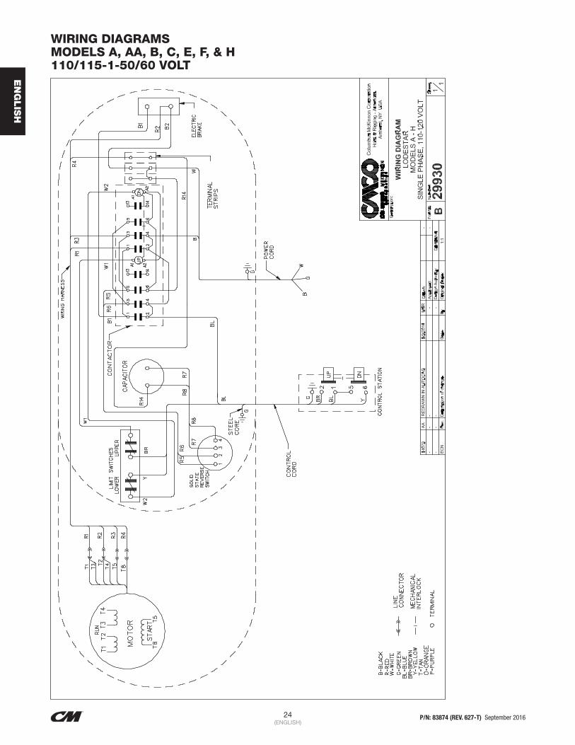
24 P/N: 83874 (REV. 627-T) September 2016(ENGLISH)
EN
GLIS
H
WIRING DIAGRAMS MODELS A, AA, B, C, E, F, & H 110/115-1-50/60 VOLT

25 P/N: 83874 (REV. 627-T) September 2016(ENGLISH)
EN
GLIS
H
WIRING DIAGRAMS MODELS A, AA, B, C, E, F, H 220/230-1-50/60 VOLT

26 P/N: 83874 (REV. 627-T) September 2016(ENGLISH)
EN
GLIS
H
WIRING DIAGRAMS MODELS A, AA, B, C, E, F, & H 220/230-3-50/60 OR 380/415/460-3-50/60 VOLT

27 P/N: 83874 (REV. 627-T) September 2016(ENGLISH)
EN
GLIS
H
WIRING DIAGRAMS MODELS A, AA, B, C, E, F, & H 220/230-3-50/60 OR 380/415/460-3-50/60 VOLT CSA UNITS

28 P/N: 83874 (REV. 627-T) September 2016(ENGLISH)
EN
GLIS
H
WIRING DIAGRAMS MODELS A-2, AA-2, B-2, C-2, E-2, F-2, & H-2 220/230-3-50/60 VOLT

29 P/N: 83874 (REV. 627-T) September 2016(ENGLISH)
EN
GLIS
H
WIRING DIAGRAMS MODELS A-2, AA-2, B-2, C-2, E-2, F-2, & H-2 220/230-3-50/60 VOLT CSA UNITS

30 P/N: 83874 (REV. 627-T) September 2016(ENGLISH)
EN
GLIS
H
WIRING DIAGRAMS MODELS A-2, AA-2, B-2, C-2, E-2, F-2, & H-2 380/415/460-3-50/60 VOLT
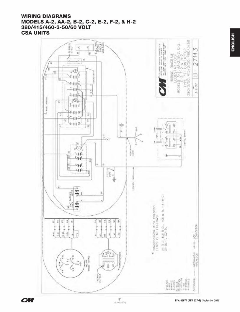
31 P/N: 83874 (REV. 627-T) September 2016(ENGLISH)
EN
GLIS
H
WIRING DIAGRAMS MODELS A-2, AA-2, B-2, C-2, E-2, F-2, & H-2 380/415/460-3-50/60 VOLT CSA UNITS

32 P/N: 83874 (REV. 627-T) September 2016(ENGLISH)
EN
GLIS
H
WIRING DIAGRAMS MODELS A-, AA, B, C, E, F & H 550/575-3-50/60 VOLT
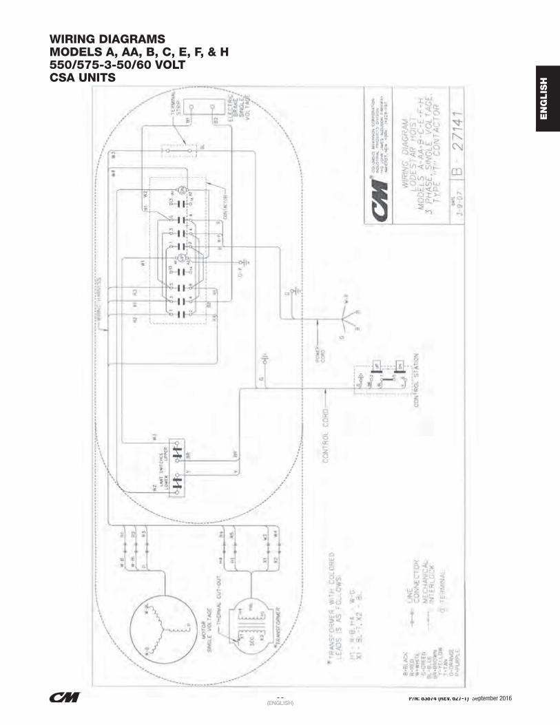
33 P/N: 83874 (REV. 627-T) September 2016(ENGLISH)
EN
GLIS
H
WIRING DIAGRAMS MODELS A, AA, B, C, E, F, & H 550/575-3-50/60 VOLT CSA UNITS

34 P/N: 83874 (REV. 627-T) September 2016(ENGLISH)
EN
GLIS
H
WIRING DIAGRAMS MODELS A-2, AA-2, B-2, C-2, E-2, F-2, & H-2 550/575-3-50/60 VOLT

35 P/N: 83874 (REV. 627-T) September 2016(ENGLISH)
EN
GLIS
H
WIRING DIAGRAMS MODELS A-2, AA-2, B-2, C-2, E-2, F-2, & H-2 550/575-3-50/60 VOLT CSA UNITS

36 P/N: 83874 (REV. 627-T) September 2016(ENGLISH)
EN
GLIS
H
WIRING DIAGRAMS MODELS J, L, R, & RT 110/115-1-50/60 VOLT

37 P/N: 83874 (REV. 627-T) September 2016(ENGLISH)
EN
GLIS
H
WIRING DIAGRAMS MODELS J, L, R & RT 220/230-1-50/60 VOLT

38 P/N: 83874 (REV. 627-T) September 2016(ENGLISH)
EN
GLIS
H
WIRING DIAGRAMS MODELS J, JJ, L, LL, R, RR, RT & RRT 220/230-3-50 OR 380/415/460-3-50/60 VOLT

39 P/N: 83874 (REV. 627-T) September 2016(ENGLISH)
EN
GLIS
H
WIRING DIAGRAMS MODELS J, JJ, L, LL, R, RR, RT & RRT 220/230-3-50/60 OR 380/415/460-3-50/60 VOLT CSA UNITS

40 P/N: 83874 (REV. 627-T) September 2016(ENGLISH)
EN
GLIS
H
WIRING DIAGRAMS MODELS J-2, JJ-2, L-2, LL-2, R-2, RR-2, RT-2 & RRT-2 220/230-3-50/60 VOLT

41 P/N: 83874 (REV. 627-T) September 2016(ENGLISH)
EN
GLIS
H
WIRING DIAGRAMS MODELS J-2, JJ-2, L-2, LL-2, R-2, RR-2, RT-2 & RRT-2 220/230-3-50/50 VOLT SA UNITS

42 P/N: 83874 (REV. 627-T) September 2016(ENGLISH)
EN
GLIS
H
WIRING DIAGRAMSMODELS J-2, JJ-2, L-2, LL-2, R-2, RR-2, RT-2 & RRT-2380/415/460-3-50/60 VOLT

43 P/N: 83874 (REV. 627-T) September 2016(ENGLISH)
EN
GLIS
H
WIRING DIAGRAMSMODELS J-2, JJ-2, L-2, LL-2, R-2, RR-2, RT-2 & RRT-2380/415/460-3-50/60 VOLTCSA UNITS

44 P/N: 83874 (REV. 627-T) September 2016(ENGLISH)
EN
GLIS
H
WIRING DIAGRAMSMODELS J, JJ, L, LL, R, RR, RT & RRT550/575-3-50/60 VOLT

45 P/N: 83874 (REV. 627-T) September 2016(ENGLISH)
EN
GLIS
H
WIRING DIAGRAMSMODELS J, JJ, L, LL, R, RR, RT& RRT550/575-3-50/60 VOLTCSA UNITS

46 P/N: 83874 (REV. 627-T) September 2016(ENGLISH)
EN
GLIS
H
WIRING DIAGRAMSMODELS J-2, JJ-2, L-2, LL-2, R-2, RR-2, RT-2 & RRT-2550/575-3-50/60 VOLT

47 P/N: 83874 (REV. 627-T) September 2016(ENGLISH)
EN
GLIS
H
WIRING DIAGRAMSMODELS J-2, JJ-2, L-2, LL-2, R-2, RR-2, RT-2 & RRT-2550/575-3-50/60 VOLTCSA UNITS

48 P/N: 83874 (REV. 627-T) September 2016(ENGLISH)
EN
GLIS
H
ASSEMBLY INSTRUCTIONS
HOOK OR LUG SUSPENSION Models E, H, R, RR, E-2, H-2, R-2 and RR-2.
Assemble the dead end bolt and block through the suspension adapter as shown in Figure 19.
Figure 19. Hook Suspension
WEATHERPROOF HOISTCheck to see that the control station, gasket, neoprene grommet, cover gaskets, motor housing and gear housing gaskets are in good condition and in correct position when reassembling.
GEARING Models JJ, LL, RR, JJ-2, LL-2, RR-2, RRT and RRT-2 have a special Liftwheel Gear (627-303) and Intermediate Pinion (627-325).
If the gear train in these hoists is disassembled, the following steps must be observed in order to properly orient the three parts when reassembling:
1. Assemble liftwheel gear to liftwheel NOTE: These parts have their splines keyed in such a way that they will go together only one way. See Figure 20.
2. To install the intermediate pinion, align the arrows that are stamped on the pinion and liftwheel gear so they point toward each other.
3. Check operation of gear train by rotating the pinion four (4) complete revolutions; liftwheel gear will turn one (1) complete revolution and the arrows will again be aligned as shown. If the arrows do not align or there is binding between the gear teeth, repeat the above steps.
4. For gearing lubrication instructions, see page 15
Figure 20. Non-Circular Gearing
FASTENERS Models A thru H-2 tighten motor housing screws (627-108) to where they have a minimum breakaway torque of 48 pound inch and the brake attaching screws (627-253) have 50 pound inch (5.649 Nm) minimum breakaway torque.
Models J thru RRT-2 tighten limit switch attaching screws (627-220), brake attaching screws (627-253) and hexagonal brake stud (627-265) to where they have a minimum breakaway torque of 50 pound inch (5.649 Nm). The liftwheel gear nut (627-305) should be tighten to a seating torque of 85 pound feet (115 Nm).
LOWER HOOK BLOCK PIN When removing or installing the lower hook block pin (627- 764), care must be taken so as to prevent damaging the pin and/or hook block. These pins are tapered groove pins and as a result, they can only be removed in one direction. To remove the pin, a V-Block, drift and hammer (or slow acting press) are required. The drift should be the same diameter as the pin (5/16” (7.94 mm) diameter for Models A, A-2, AA, AA-2, B, B-2, C, C-2, F and F-2; and 3/8” diameter (9.52 mm) for Models J, J-2, JJ, JJ-2, L, L-2, LL and LL-2), and it should be placed at the small end of the pin. The small end of the pin is the end opposite the end on which the 3 grooves are visible. Place the hook block in the V-Block and drive the pin out using the drift and a hammer or slow acting press.
To re-install the pin, the parts must be arranged the same as they were when the pin was removed. To do this, use the small end of the pin as a gage. First check the holes in the hook block body and determine which holes is the largest. Place the hook block body in the V-Block with the larger hole on top. Next, check each end of the hole in the lower chain block (627-775) and determine which end is the largest. Place the chain in the slot of the chain and insert the chain block, with the large hole on top, into the hook body. Align the holes in the hook block body with the hole in the chain block and insert the small end if the pin in the hole. Push the pin in by hand until it stops and then use a hammer or slow acting press to drive the pin into position so that the end of the pin is flush with the outside surface of the hook body.
Use of improper lower hook chain block pin as well as improper installation of this pin can cause the pin to break and allow the load to fall.
TO AVOID INJURY:
Use only CM supplied, special high strength lower hook chain block pin to attach the chain to the lower hook block and install the pin as directed above.
REMOVAL AND INSTALLATION OF LOAD CHAIN
Improper installation (reeving) of the load chain can result in a dropped load.
TO AVOID INJURY:
• Verify use of proper size and type of hoist load chain for specific hoist.
• Install load chain properly as indicated below.
USE ONLY CM STAR (H) GRADE LOAD CHAIN AND CM REPLACEMENT PARTS. USE OF OTHER CHAIN AND PARTS MAY BE DANGEROUS AND VOIDS FACTORY WARRANTY.

49 P/N: 83874 (REV. 627-T) September 2016(ENGLISH)
EN
GLIS
H
Use of commercial or other manufacturers’ chain and parts to repair CM hoists may cause load loss.
TO AVOID INJURY:
Use only CM supplied replacement load chain and parts. Chain and parts may look alike, but CM chain and parts are made of specific material or processed to achieve specific properties.
NOTE: When installing load chain in Models E, H, R, RR, E-2, H-2, R-2 and RR-2 by either of the “starter chain” methods, two loose end connecting links (627-743) must be used.
Hoist load chain can be installed by any one of several methods. The first method is recommended when replacing severely worn load chain and requires disassembling the hoist. Method 2 does not require hoist disassembly, whereas Method 3 requires only partial disassembly.
Method #11. Disconnect hoist from power supply.
2. Remove back frame cover and disengage the limit switch guide plate from the traveling nuts, see page 16 or 17.
3. Detach loose end of load chain from hoist frame, see Figure 7. Also on single reeved models, detach the lower hook block from the load chain. On double reeved models E, H, R, RR, E-2, H-2, R-2, and RR-2, unfasten the dead end side of the load chain. On triple reeved Models RT, RRT, RT-2 and RRT-2, detach the load chain from the lower hook block.
4. Continue to disassemble the hoist and inspect the liftwheel, chain guides, motor housing and gear housing which if worn or damaged could cause early failure of the new chain. Parts can be easily identified by referring to pages 51 thru 85.
5. If the liftwheel pockets, in particular the ends, are worn or scored excessively, replace the liftwheel. If chain guides and housing are worn or cracked, these parts should be replaced.
6. Reassemble hoist with the new load chain inserted over the liftwheel. Position chain with the weld on upstanding links away from liftwheel and leave only one foot of chain hanging free on loose end side. Make sure the last chain link is an upstanding link. On double reeved models, make sure that the new load chain has an even number of links. On triple reeved models, make sure that the new chain has an odd number of links. This will prevent twist in chain. To simplify handling when reassembling the hoist, a short undamaged piece of the old chain may be used as a “starter chain”. Position this piece of chain in exactly the same manner as explained above for the “new chain”, and complete the reassembly of the hoist.
7. Attach the loose end link to chain and connect it to the hoist frame with the loose end screw, washer and lockwasher, see Figure 7. BE SURE THERE IS NO TWIST. If a starter chain is used, the loose end link (two links required for double reeved models) can serve as a temporary coupling link to connect together the starter chain in the hoist and the
new load chain to be installed. Then, under power, reeve the new load chain through the liftwheel area, replacing the starter chain in unit. Run enough chain through to attach loose end link to hoist frame.
Caution: For double reeved models, be sure to disconnect one of the loose end links from load chain before attaching to hoist frame.
8. For single reeved models, attach the hook block to load chain.
9. For double reeved models, run the hoist p (UP) until only 3 feet (.9 M) in chain remains on dead end side. This will minimize the chance of introducing a twist between hook block and hoist. Allow the chain to hang free to remove twists. Using a wire as a starter, insert the chain, flat link first, into lower hook block (upstanding links will have weld toward sheave) and pull through. Insert last link into slot in dead end block making sure that no twist exists in the reeving at any point. Assemble dead end pin, washer and cotter pin as shown in Figure 7.
10. For triple reeved models, run the hoist p(UP) until only 4 feet (1.2 M) of chain remains on the dead end side. This will minimize the chance of introducing a twist between the hook block and hoist. Allow the chain to hang free to remove twists. Using a wire as a starter, insert the chain, upstanding link first, into lower hook block (upstanding links will have welds toward sheave) and pull through. Using a wire as a starter, insert the chain, upstanding link first, into the outboard cloverleaf of the hanger. Make sure there are no twists between the hook block and then pull the chain through. In the sheave hanger, the upstanding links will have the welds toward the sheaves. Run the chain down to the hook block and making sure there are no twists between the sheave hanger and the hook block, insert the end of the chain into the recess in the top of the hook block. Slide the dead end screw, with flat sides vertical, through the hole in the top of the hook block. Place the lockwasher and nut on the threaded end of the dead end screw. Use an Allen wrench to hold the head of the dead end screw stationary and rotate the nut to tighten. To properly tighten the nut, apply a torque of 45 (61Nm) to 55 pound feet (74.6 Nm) while holding the head of the dead end screw stationary. Also, when tightening this dead end screw, it should be held firmly in position and torqued from the nut end to avoid damaging the screw and/or chain.
11. Adjust limit switches as described on pages 16 and 17. If the new chain is longer than the old, check to be sure limit switch will allow for new length of lift. In the event maximum adjustment does not allow entire length of lift, check with CM for modification necessary. Do not allow hook block to hit hoist or allow load chain to become taut between loose end screw and frame or else serious damage will result. If hook should inadvertently hit the hoist-the hoist frames, load chain and hook block should be inspected for damage before further use.
Method #2 Treat the old load chain in hoist as a “starter chain” and proceed with Steps 1a, b, c and f thru k above.
Method #3 1. First proceed with Steps 1a, b, c above.
2. Then, carefully run the load chain out of the hoist.
3. Disconnect hoist from power supply.
4. Remove the electric brake assembly.
5. Rotate the brake hub by hand, at the same time feeding the load chain through the liftwheel area with hoist upside down or by using a wire to pull the load chain up onto the liftwheel. Position the chain on the liftwheel as explained in Step 1f.
6. Refer to Steps 1g thru k above to complete the installation.
ASSEMBLY INSTRUCTIONS (CONTINUED)

50 P/N: 83874 (REV. 627-T) September 2016(ENGLISH)
EN
GLIS
H
CUTTING CHAINS CM HoistAloy® load chain is hardened and it is difficult to cut. The following methods are recommended when cutting a length of new chain from stock or cutting off worn chain.
1. Use a 7” (177.8 mm) minimum diameter by 1/8” (3.175 mm) thick abrasive wheel (or type recommended by wheel supplier) that will clear adjacent links.
2. Use a bolt cutter (Figure 22) similar to the H.K. Porter No. 0590MTC with special cutter jaws for cutting hardened chain (1” (25.4 mm)long cutting edge).
Figure 22. Cutting Chain with a Bolt Cutter
Cutting Chain Can Produce Flying Particles.
TO AVOID INJURY:
• Wear Eye Protection.
• Provide A Shield Over Chain To Prevent Flying Particles.
TESTING Before using, all altered, repaired or used hoists that have not been operated for the previous 12 months shall be tested by the user for proper operation. First, test the unit without a load and then with a light load of 50 pounds (22.7 kg) times the number of load supporting parts of load chain to be sure that the hoist operates properly and that the brake holds the load when the control is released. Next test with a load of *125% of rated capacity. In addition, hoists in which load sustaining parts have been replaced should be tested with *125% of rated capacity by or under the direction of an appointed person and written report prepared for record purposes. After this test, check that the Protector functions. If the Protector permits lifting a load in excess of 200% of rated metric load, it should be replaced.
NOTE: For additional information on inspection and testing, refer to Code B30.16 “Overhead Hoist” obtainable from ASME Order Department, 22 Law Drive, Box 2300, Fairfield, NJ 07007-2300, U.S.A.
* If the Protector prevents lifting of a load of 125% of rated capacity, reduce load to rated capacity

51 P/N: 83874 (REV. 627-T) September 2016(ENGLISH)
EN
GLIS
H
NOTES

52 P/N: 83874 (REV. 627-T) September 2016(ENGLISH)
EN
GLIS
H
REPAIR PARTS LIST
Using “Commercial” or other manufacturer’s parts to repair the CM Lodestar Hoists may cause load loss.
TO AVOID INJURY:
Use only CM supplied replacement parts. Parts may look alike but CM parts are made of specific materials or processed to achieve specific properties.
ORDERING INSTRUCTIONSThe following information must accompany all correspondence orders for replacement parts:
1. Hoist Model Number from identification plate.
2. Serial number of the hoist stamped below identification plate.
3. Voltage, phase, hertz from the identification plate.
4. Length of lift.
5. Part number of part from parts list.
6. Number of parts required.
7. Part name from parts list.
NOTE: When ordering replacement parts, it is recommended that consideration be given to the need for also ordering such items as gaskets, fasteners, insulators, etc. These items may be damaged or lost during disassembly or just unfit for future use because of deterioration from age or service.

53 P/N: 83874 (REV. 627-T) September 2016(ENGLISH)
EN
GLIS
HKey No. Part Name
Models and Voltages
A, B, and E AA, C, F and H
110-1-50115-1-60
220-1-50230-1-60 230/460 575-3-60 110-1-50
115-1-60220-1-50230-1-60 230/460 575-3-60
627-250 Electric Brake Assembly – Complete 27656 27656 27659 27658 27681 27681 27684 27683
627-259 Brake Coil 51517 51517 51518 51520 51517 51517 51518 51520
627-310 Drive Shaft & Pinion S/A(items 627-311 thru 627-315, as applicable)
27653 27654
627-413 Rotor & Shaft Assembly 286005 286005 286004 286004 286001 286001 286000 286000
627-415 Stator
287007(60 HZ)
286007(60 HZ)
287006 287009
287002(60 HZ)
286006(60 HZ)
287001 287005286008(50 HZ)
286009(50 HZ)
286010(50 HZ)
286011(50 HZ)
Key No. Part Name
Models and Voltages
A-2, B-2 and E-2 AA-2, C-2, F-2 and H-2
230-3-60 460-3-60 575-3-60 230-3-60 460-3-60 575-3-60
627-250 Electric Brake Assembly – Complete 27659 27655 27683 27684 27656 27683
627-259 Brake Coil 51518 51519 51520 51518 51519 51520
627-310 Drive Shaft & Pinion S/A(items 627-311 thru 627-315, as applicable)
27654 27654
627-413 Rotor & Shaft Assembly 286002 286003 286003 286003 286003 286003
627-415 Stator 286011 287004 287010 287003 287004 287010
Key No. Part Name
Models and Voltages
J, L, R, and RT JJ, LL, RR, and RRT
115-1-60 230-1-50/60 230/460 575-3-60 230/460 575-3-60
627-250 Electric Brake Assembly – Complete 35646 35646 35647 35649 35648 36688
627-259 Brake Coil 51510 51510 51511 51515 51512 51516
627-310 Drive Shaft & Pinion S/A(items 627-311 thru 627-315, as applicable)
35688 (18 Teeth and 13 Teeth Hub) for Models J, J-2, JJ, & JJ-2
35687(12 Teeth and 13 Teeth Hub) for Models L, L-2, LL, LL-2, R, R-2, RR, RR-2, RT, Rt-2, RRT, and RRT-2
627-411 Attaching Screws 87377 87377 87377 87377 87336 87377
627-415 *3/4 Motor Assembly 367001 367028 **367040K 367003 **367050K 367009
627-415A Motor End Plate 367023
Key No. Part Name
Models and Voltages
J-2, L-2, 4-2, and RT-2 JJ-2, LL-2, RR-2, AND RRT-2
230-3-60 460-3-60 575-3-60 230-3-60 460-3-60 575-3-60
627-250 Electric Brake Assembly – Complete 35647 35622 35649 35648 35623 36688
627-259 Brake Coil 51511 51513 51515 51512 51514 51516
627-310 Drive Shaft & Pinion S/A(items 627-311 thru 627-315, as applicable)
35688 (18 Teeth and 13 Teeth Hub) for Models J, J-2, JJ, & JJ-2
35687(12 Teeth and 13 Teeth Hub) for Models L, L-2, LL, LL-2, R, R-2, RR, RR-2, RT, Rt-2, RRT, and RRT-2
627-411 Attaching Screws 87336 87336 87336 87336 87336 87336
627-415 *3/4 Motor Assembly 367014 367015 367018 367020 367021 367022
627-415A Motor End Plate 367023
*3/4 Motor includes Stator, Rotor and Shaft Assembly and End Bell.
**Motor Kit Includes ‘B1’ & ‘B2’ Brake Jumpers.
Note: Except as indicated above, Electric Brake Assemblies, Brake Coils, Rotor Assemblies and Stators listed under “230/460” are also suitable for operation on 220/380-3-50 or 220/415-3-50. Those listed under “230” are also suitable for operation on 220-3-50 and those listed under “460” are also suitable for operation on 380-3-50 or 415-3-50.
Note: CM Extraction Tool Code 27163 Can Be Ordered Separately for Removal of Individual Wires from Motor or Wiring Harness Plugs.
PART NUMBERS FOR BRAKE COILS, BRAKE ASSEMBLIES, ROTORS, STATORS AND ATTACHING SCREWS
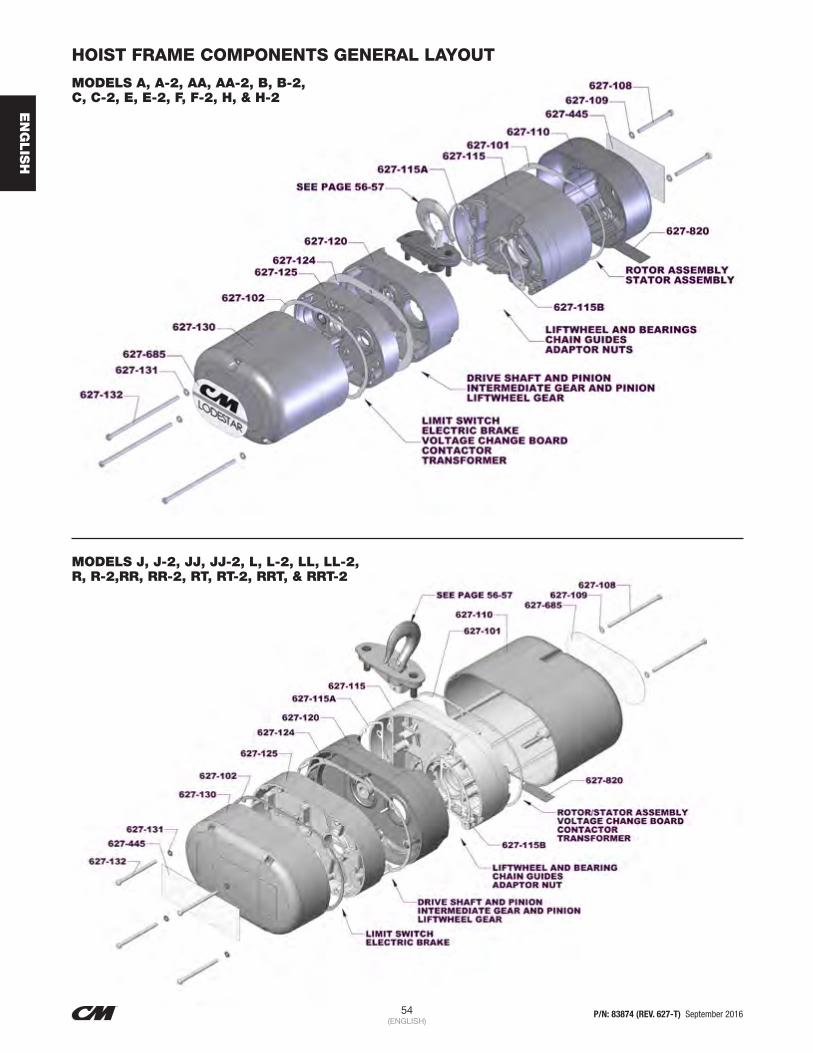
54 P/N: 83874 (REV. 627-T) September 2016(ENGLISH)
EN
GLIS
H
HOIST FRAME COMPONENTS GENERAL LAYOUT
MODELS A, A-2, AA, AA-2, B, B-2, C, C-2, E, E-2, F, F-2, H, & H-2
MODELS J, J-2, JJ, JJ-2, L, L-2, LL, LL-2, R, R-2,RR, RR-2, RT, RT-2, RRT, & RRT-2

55 P/N: 83874 (REV. 627-T) September 2016(ENGLISH)
EN
GLIS
H
HOIST FRAME COMPONENTS
Key Number Part Name No.
Req'd
Models
A, A-2, AA, AA-2, B, B-2, C, C-2, F, F-2
E, E-2, H, H-2J, J-2, JJ,
JJ-2, L, L-2, LL, LL-12
R, R-2, RR, RR-2
RT, RT-2, RRT, RRT-2
Part Number
627-101 Motor Housing Cover Gasket (Weatherproof Units Only) 1 27847 35845
627-102 Back Frame Cover Gasket (Weatherproof Units Only) 1 27848 35840
627-107 Motor Cover and Back Frame Cover Alignment Pins 8 — 983784
627-108 Motor Housing Cover Screws 2 987397 987553
627-109
Motor Housing Cover Screw Lockwashers
2 Standard Units 982226 982226
Weatherproof Units 982251 982251
627-110
Motor Housing Cover
1
Orange 27597
(Includes 627-402, 446 & 447) 36071
Black 27059
(Includes 627-402,446, 447) 36076
CSA Covers w/drain slot (Orange) 27095 36023
627-115
Motor Housing
1 Orange 27028C 24008C 36078
Black 27028B 24008B —
627-115A Motor Housing Wire Way Gasket 1 28993 29002
627-115B Motor Housing Spacer Gasket 1 28996 29001
627-120
Gear Housing
1 Orange 28669 35620 36604
Black 28672 35627 —
627-124 Gear Housing Gasket 1 27747 35707
627-125
Back Frame
1 Orange 27618
(Includes 627-123 & 627-211) 35090
Black 27625
(Includes 627-123 & 627-211) 35095 —
627-130
Back Frame Cover
1
Orange 28009C 36008C (Also order 627-445)
Black 28009B36008B (Also
order 627-445)
CSA Cover w/drain slot (Orange) 27097 36022 (Also order 627-445)
627-131
Back Frame Cover Screw Lockwasher
As Req'd Standard Units 982226 (3 Required) 982226 (4 Required)
Weatherproof Units 982251 (3 Required) 982251 (4 Required)
627+132 Back Frame Cover Screw As Req'd 87325 (3 Required) 968752 (4 Required)
627-245 Back Frame Seal Screw — 982623
627-445 Capacity Label 27276 (1/8 Ton), 27277 (1/4 Ton),
27278 (1/2 Ton), 27279 (1 Ton) 35200 (1/2 Ton), 35201 (1 Ton),
35202 (2 Ton), 35203 (3 Ton)
627-685 Series Label 1 27238 36840
627-820 Electrical Warning Label 1 24842

56 P/N: 83874 (REV. 627-T) September 2016(ENGLISH)
EN
GLIS
H
LODESTAR HOIST UPPER SUSPENSION
627-700COMPLETE SWIVEL HOOK SUSPENSION
627-710COMPLETE RIGID HOOK SUSPENSION
627-720COMPLETE LUG SUSPENSION
TRIPLE REEVED SUSPENSION& SHEAVE HANGER

57 P/N: 83874 (REV. 627-T) September 2016(ENGLISH)
EN
GLIS
H
UPPER SUSPENSION COMPONENTS
Key Number Part Name No.
Req'd
Models
A, A-2, AA, AA-2, B, B-2, C, C-2, F, F-2
E, E-2, H, H-2J, J-2, JJ,
JJ-2, L, L-2, LL, LL-12
R, R-2, RR, RR-2
RT, RT-2, RRT, RRT-2
Part Number
627-700
Swivel Hook Suspension(Includes 627-701 thru 627-706 for Models A, A-2, AA, AA-2, B, B-2, C, C-2, F, F-2, J, J-2, JJ, JJ-2, L, L-2, LL, & LL-2.) (Includes 627-701 thru 627-706, 627-830 & 627-833 thru 627-836 for Models E, E-2, H,H-2, R, R-2, RR & R-2) (Includes 627-701 thru 627-703, 627-705 & 627-7-6 for Models RT, RT-2, RRT & RRT-2)
12792
(Latch Type Hook)
2793(Latch Type
Hook)
3661(Latch Type
Hook)
3660(Latch Type
Hook)
9557(Latch Type
Hook)
627-701
Upper Hook Latch Type
1 28689 28697 35617 35616 35613
Latchlok Type 1 28643 28602 36678 36680 36694
627-702 Suspension Adapter Screw 1 27529 35588
627-703 Suspension Adapter 1 27003B 27013 35740B 35741BOrder Complete
Suspension
627-704 Upper Hook Washer (Swivel Hook Suspension Only) 1 27786 45930 45930 45918 —
627-705 Upper Hook Collar Nut (Swivel Hook Suspension Only) 1 27350 45385 35042 35041 36352
627-706Upper Hook or Suspension Lug Pin (Special Alloy Steel) Specify for Rigid or Swivel Type Suspension
1 27805 45941983763 (Rigid) 983761 (Rigid)
983762983764 (Swivel) 983762 (Swivel)
627-710
Rigid Hook Suspension(Includes 627-701 thru 627-703, 627-706 & 627-711 for Models A, A-2, AA, AA-2 B, B-2, C, C-2, F, F-2, J, J02, JJ, JJ-2, L, L-2, LL, & LL-2) (Includes 627-702, 627-703, 627-706, 627-711, 627-733, 627-830 & 627-833, thru 627-836 for Models E, E02, H, H-2, R, R-2, RR & R-2. (Includes 627-702, 627-703, 627-706, 627-711, 627-728, 627-729 thru 627-730 for Models RT, RT-2, RRT & RRT-2
*2788(Latch Type
Hook)
*2789(Latch Type
Hook)
*3651(Latch Type
Hook)
*3658(Latch Type
Hook)
*9559(Latch Type
Hook)
627-711Upper Hook or Suspension Lug Collar (For Rigid Hook and Lug Suspension)
1 27361 27370 35458 35479 **36360
627-716 Latch Kit 1 45661 45662 45662 45663 45663
627-720
Lug Suspension(Includes 627-702, 627-703, 627-706 & 627-711 & 627-721A for Models A, A-2, AA, AA-2, B, B-2, C, C-2, F, F02, J, J-2, JJ, JJ-2, L, L-2, LL, & LL-2 (Includes 627-702, 627-703, 627-706, 627-711, 627-721A, 627-830 & 627-823 thru 627-836 for Models E, E-2, H, H-2, R, R-2, RR & RR-2) (Includes 627-702, 627-703, 627-7-6, 627-711, 627-728, 627-729 and 627-730 for Models RT, RT-2, RRT & RRT-2
1
2778 for Series 635 Low
Headroom Trolley
2779 for Series 635 Low
Headroom Trolley
3677 for Series 635 Low
Headroom Trolley3668 9561
2992 for Series 635 Motor
Driven Trolley
2993 for Series 635 Motor
Driven Trolley
3679 for Series 635 Motor
Driven Trolley
627-721A
Suspension Lug For Series 635 Low Headroom Trolley
27450 27452 35456 35457
For Series 635 Motor Driven Trolley 27454 27455 35459 35457
627-721B
Suspension Lug 1 Contact Factory
Special High Strength Bolts, Grade 6 or better required for attachment
1 C246
627-723 Cloverleaf Plate & Attaching Screws C247
627-724Sheave Stud 2/washer, Slotted Nut, Seat and Retainer Pin
36011
627-725 Sheave Hanger 88429
627-726 Sheave Hanger Bearing 36350
627-727 Upper SheaveOrder Complete
Suspension
627-728 Suspension LugOrder Complete
Suspension
627-729 Shackle w/Pin and Retainer Rings C248
627-730 Suspension Lug Pin w/Retainer Pins 40740
627-731 Bearing Retainer Ring
627-830 Dead End Bolt (Special Alloy) 1 89508 35957
627-833 Dead End Block 1 27397 35418
627-834 Dead End Pin 1 82320 82314
627-835 Dead End Pin Cotter Pin 1 988330 988330
627-836 Dead End Pin Washer 1 987878 987877

58 P/N: 83874 (REV. 627-T) September 2016(ENGLISH)
EN
GLIS
H
LODESTAR LOWER HOOK BLOCK ASSEMBLY
627-760COMPLETE SINGLE REEVED
LOWER HOOK BLOCK ASSEMBLY
627-860COMPLETE DOUBLE REEVED
LOWER HOOK BLOCK ASSEMBLY
627-860TRIPLE REEVED
LOWER HOOK BLOCK ASSEMBLY

59 P/N: 83874 (REV. 627-T) September 2016(ENGLISH)
EN
GLIS
H
LOWER HOOK BLOCK ASSEMBLY
Key Number Part Name No.
Req'd
Models
A, A-2, AA, AA-2, B, B-2, C, C-2, F, F-2
E, E-2, H, H-2J, J-2, JJ,
JJ-2, L, L-2, LL, LL-12
R, R-2, RR, RR-2
RT, RT-2, RRT, RRT-2
Part Number
627-716 Latch Kit (specify no. req’d) — 45661 45662 45662 45663 45663
627-722 Hook Block Screws with Nuts and Lockwasher (2 Each) 1 — C245
627-732 Dead End Screw with Nut and Lockwasher 1 — C249
627-760 Lower Hook Block Assembly 1 **28683 — 35651 — 36607
627-763 Lower Hook Body 1 45401B — 35370 —
627-764 Lower Hook Chain Block Pin 1 45943 — 35790 —
627-770 Lower Hook Block Assembly 1 — *28665 — *35645 *36606
627-771
Lower Hook with Latch: Latch Type Hook
1 28686 28687 35611 35612 36606
Latchlok Type Hook 1 28604 28603 28604 36681 ***
All Other Hook Types 1 Contact Factory
627-772 Lower Hook Thrust Bearing 1 88485 88478 88485 88505 8850
627-773 Lower Hook Collar 1 — 27359 — 35478 —
627-774 Lower Hook Pin 1 983772 45941 983772 45946 983762
627-775 Lower Hook Chain Block 1 28007 — 35026 —
627-776 Lower Hook Nut 1 982526 — 982526 — 36352
627-777 Lower Hook Block Washer 1 945921 945921 —
627-833 Dead End Block 1 — 27397 — 35418 —
627-834 Dead End Pin 1 — 82320 — 82314 —
627-835 Dead End Pin Cotter Pin 1 — 988330 — 988330 —
627-836 Dead End Pin Washer 1 — 987878 — 987877 —
627-837 Contact Block 1 — — — 36764 —
627-860 Lower Hook Block Assembly-Complete 1 — **28685- — **0000277B *36607
627-861 Hook Block Sheave 1 — 27017 — 00000274 36351
627-862 Hook Block Sheave Bearing 2 — 88429 — 83674 83670
627-863 Hook Block (Order in Pairs) 2 — 27048 — 36032 36010
627-864 Hook Block Screw-Long 2 — 982066 — 982374 —
627-865 Hook Block Screw-Short 1 — 986191 — 982370 —
627-866 Hook Block Screw L.W. 3 — 940802 — 940830 —
627-867 Hook Block Screw Nut 3 — 982514 — 982445 —
*Contact CM for Part Number of Suspension with Latchlok Type Hook.
**Latch Type Hook. Contact CM for Part Number of Lower Hook and Body with Latchlok Type Hook.
***For Swivel Hook Nut, Part Number is 36352.

60 P/N: 83874 (REV. 627-T) September 2016(ENGLISH)
EN
GLIS
H
LODESTAR HOIST CONTROL END COMPONENTS
MODELS A, A-2, AA, B, B-2, C, C-2, E, E-2, F, F-2, H, H-2
MODELS J, J-2, JJ, JJ-2, L, L-2, LL, LL-2, R, R-2, RR, RR-2, RT, RT-2, RRT, RRT-2
CONTROL AND POWER CORDS

61 P/N: 83874 (REV. 627-T) September 2016(ENGLISH)
EN
GLIS
H
CONTROL END COMPONENTS
Key Number Part Name No.
Req'd
Models
A, A-2, AA, AA-2, B, B-2, C, C-2, F, F-2
E, E-2, H, H-2J, J-2, JJ,
JJ-2, L, L-2, LL, LL-12
R, R-2, RR, RR-2
RT, RT-2, RRT, RRT-2
Part Number
627-123 Back Frame Expansion Plug 1 940837 —627-127 Back Frame Attaching Screw 3 4 982699 982682
627-127A Back Frame Attaching Screw Lockwasher 3 4 940802 940802627-128 Back Frame Attaching Screw 2 — — 982698 (1 3/4” lg.)
627-128A Back Frame Attaching Screw Lockwasher 2 — — 940830627-129 Back Frame Attaching Screw 2 — — 987322 (2” lg)
627-129A Back Frame Attaching Screw Lockwasher 2 — — 940830
627-220Limit Switch Shaft & Gear Kit
1— — 36641 (See Separate Parts List on Page 64)
Rotatable Limits — — 36656 (See Separate Parts List on Page 64)627-222 Limit Switch Kit 1 — — 31636 (See Separate Parts List on Page 64)627-250 Electric Brake Assembly - Complete 1 See Separate Parts List on Page 62-63627-252 Brake Attaching Screw Lockwasher – 982226 (2 Req’d) 945851 (1 Req’d)627-253 Brake Attaching Screw – 982708 (2 Req’d) 982709 (1 Req’d)627-257 Brake Stud Nut 2 945840627-263 Hex Brake Stud Spring 1 57753 35831627-264 Hex Brake Stud Spring Washer 1 — — 954807627-265 Hex Brake Stud 1 — — 36674627-272 Hex Brake Stud Lockwasher 1 — — 982232627-471 Control Cord Attaching Screw 1 987827627-472 Control Cord Attaching Screw Washer 1 927835627-473 Control Cord Attaching Screw Lockwasher 1 982226627-528 Transformer Attaching Screw 2 — — 982688
627-530
Transformer:
1
220/230 Volt Primary w/115 Volt Secondary
See page 72-77
29070220/230 Volt Primary w/48 Volt Secondary 29071220/230 Volt Primary w/24 Volt Secondary 29072220/230 Volt Primary w/115 Volt Secondary with Thermal Cutout for CSA
29075
220/230 Volt Primary w/48 Volt Secondary with Thermal Cutout for CSA
29076
220/230 Volt Primary w/24 Volt Secondary with Thermal Cutout for CSA
29077
110/115 Volt Primary w/48 Volt Secondary 29073110/115 Volt Primary w/24 Volt Secondary 29074110/115 Volt Primary w/48 Volt Secondary with Thermal Cutout for CSA
29078
110/115 Volt Primary w/24 Volt Secondary with Thermal Cutout for CSA
29079
627-602 Contactor Mounting Plate Stud 3 27836 —627-604 Contactor Mounting Plate Stud Lockwasher 3 982226 —627-605 Contactor Mounting Plate Stud Nut 3 982514 —627-686 Power Cord Attaching Screw 1 987827627-687 Power Cord Attaching Screw Lockwasher 1 982226
627-1017 Instruction Tag 1 29271 (Dual Voltage), 927992 (Single Voltage)
627-1018 Power Cord 129924 (Single Phase Units)
29925 (220/230-1-50/60 Units)27589 (Three Phase)
29042 (Single Phase Units)29430 (Three Phase Units)
627-1019 Control Cord Assembly 1 See Separate parts list on Pages 86-88627-1050 Terminal Strip 4
—
39460*627-1051 Terminal Strip End Clamp 2 39452*
627-1065 Terminal Strip Mounting Bracket 131639* (220/230-1-50/60 & 110 volt
Single Phase w/Transformers)29012 All Other Units
627-1066 Terminal Strip Mounting Screw 2 951726*627-1067 Terminal Strip Mtg. Screw Lockwasher 2 957855*627-1068 Terminal Strip Mtg. Bracket Screws 2 958805*627-1069 Terminal Strip Mtg. Bracket Screw Lockwasher 2 987873*627-1070 Terminal Strip Mtg. Bracket Screw Nut 2 988141*

62 P/N: 83874 (REV. 627-T) September 2016(ENGLISH)
EN
GLIS
H
LODESTAR HOIST BRAKE COMPONENTS
MODELS A, A-2, AA, B, B-2, C, C-2, E, E-2, F, F-2, H, H-2
MODELS J, J-2, JJ, JJ-2, L, L-2, LL, LL-2, R, R-2, RR, RR-2, RT, RT-2, RRT, RRT-2

63 P/N: 83874 (REV. 627-T) September 2016(ENGLISH)
EN
GLIS
H
BRAKE COMPONENTS
Key Number Part Name No.
Req'd
Models
A, A-2, AA, AA-2, B,B-2, C, C-2, F, F-2,
H, H-2
J, J-2, JJ, JJ-2, L, L-2, LL,LL-2, R, R-2, RR, RR-2, RT,
RT-2, RRT, RRT-2
Part Number
627-251 Brake Base Plate and Studs 1 28668 35643
627-254 Brake Intermediate Plate 1 27091 (For Models AA, AA-2, C, C-2, F, F-2, H & H-2 only)
35069
627-255 Brake Spring 2 27751 (Color Coded Blue)
35716 (Color Coded Yellow for
Models J, J-2, L-2, R, R-2, RT and RT-2)
35717 (Color Coded Green for Models JJ, JJ-2,
LL, LL-2, RR, RR-2, RRT and RRT-2)
627-256 Brake Field Sub-Assembly 1 28677 (Includes 627-262)
35629
627-257 Brake Stud Nut 2 345840
627-258 Brake Coil Retainer Strap 1 57753 35704
627-259 Brake Coil 1 See Separate Listing on Page 51
627-260 Brake Armature Assembly 1 28678 35600 (Includes 627-262)
627-261 Brake Friction Disc —27677
(1 Req’d for Models A, A-2, B, B-2, E, E-2)(2 req’d for Models AA, AA- 2, C, C-2, F, F-2, H, H-2)
35632 (2 Req’d)

64 P/N: 83874 (REV. 627-T) September 2016(ENGLISH)
EN
GLIS
H
LODESTAR HOIST LIMIT SWITCH COMPONENTS
MODELS A, A-2, AA, B, B-2, C, C-2, E, E-2, F, F-2, H, H-2
MODELS J, J-2, JJ, JJ-2, L, L-2, LL, LL-2, R, R-2, RR, RR-2, RT, RT-2, RRT, RRT-2

65 P/N: 83874 (REV. 627-T) September 2016(ENGLISH)
EN
GLIS
H
LIMIT SWITCH COMPONENTS
Key Number Part Name No.
Req'd
Models
A, A-2, AA, AA-2, B,B-2, C, C-2, F, F-2,
H, H-2
J, J-2, JJ, JJ-2, L, L-2, LL,LL-2, R, R-2, RR, RR-2, RT,
RT-2, RRT, RRT-2
Part Number
627-220Limit Switch Shaft and Gear Kit
127561 36641
Rotatable Limit Switch 27749 36656
627-220A Limit Switch Gear 1 27714 35753
627-220B
Limit Switch Shaft (44 thread)
1
70399 36373
Limit Switch Shaft (56 thread) 27307 36317
Limit Switch Shaft (64 thread) 27251 36321
627-220C
Travel Nut (44 thread)
2
70053 70053
Travel Nut (56 thread) 36318 36318
Travel Nut (64 thread) 36319 36319
627-220D Spring 1 28712 35703
627-220E Limit Switch Bearing 2 — 35751
627-220F Mounting Screws 2 — 983656
627-222Limit Switch Kit: Three Phase
131631
31636All Others 31631
627-231 Limit Switch Bracket Sub-Assembly 1 27502 36644

66 P/N: 83874 (REV. 627-T) September 2016(ENGLISH)
EN
GLIS
H
LODESTAR HOIST GEARING COMPONENTS
MODELS A, A-2, AA, B, B-2, C, C-2, E, E-2, F, F-2, H, H-2
MODELS J, J-2, JJ, JJ-2, L, L-2, LL, LL-2, R, R-2, RR, RR-2, RT, RT-2, RRT, RRT-2

67 P/N: 83874 (REV. 627-T) September 2016(ENGLISH)
EN
GLIS
H
GEARING COMPONENTS
Key Number Part Name No.
Req'd
Models
A, A-2, AA, AA-2, B,B-2, C, C-2, F, F-2,
H, H-2
J, J-2, JJ, JJ-2, L, L-2, LL,LL-2, R, R-2, RR, RR-2, RT,
RT-2, RRT, RRT-2
Part Number
627-119 Gear Housing Plug 1 — 935495
627-122 Gear Housing Attaching Screw 4 28830 982682
627-122A Gear Housing Attaching Screw Lockwasher 4 940802 940830
627-303 Liftwheel Gear 1
27010 (47 teeth)Models A, A-2, C & C-2
28380 (39 teeth) Models AA & AA-2
27009 (56 teeth)Models B, B-2, E, E-2, F, F-2, H & H-2
35009 (79 teeth) Models J, J-2, L, L-2, R, R-2, RT & RT-2
35639 (60 teeth) Models JJ, JJ-2, LL, LL-2, RR, RR-2, RRt & RRT-2
627-304 Liftwheel Gear Snap Ring 1 27767 —
627-305 Liftwheel Gear Nut 1 — 35773
627-306 Liftwheel Gear Nut Washer 1 — 986576
627-307 Liftwheel Bearing-Gear End 1 88429 82002
627-310 Drive Shaft and Pinion Sub Assembly (Includes items 627-311 thru 627-315 as applicable)
1
27654 (5-43/64” lg. shaft length) Models AA, AA-2, C, C-2, F, F-2, H & H-2
27653 (5 15/64” lg shat length) Models A, A-2, B, B-2, E & E-2
35688 (18 teeth pinion & 13 teeth hub) Models J, J--2, JJ & JJ-2
35687 (12 teeth pinion & 15 teeth hub) Models L, L-2, LL, LL-2, R, R-2, RR, RR-2,R,
RT, RT-2, RRT & RRT-2
627-311 Drive Shaft and Pinion
C204 (Models AA, AA-2, C, C-2, F, F-2, H & H-2)
C203 (Models A, A-2, B, B-2, E & E-2)
35357 (18 teeth) Models J, J-2, JJ & JJ2
35356 (12 teeth) Models L, L-2, LL, LL-2, R, R-2, RR, RR-2,
RT, RT-2, RRT & RRT-2
627-312 Drive Shaft and Pinion Bearing 1 82009 83691
627-313 Drive Shaft and Pinion Bearing Spacer 1 27710 —
627-314 Brake Hub 1
27852 (1 1/2 lg.)Models AA, AA-2, C, C-2, F, F-2, H & H-2
27851 (2 1/32 lg)Models A, A-2, B, B-2, E & E-2
35744
627-315 Brake Hub Snap Ring 1 27765 35766
627-321 Intermediate Gear and Pinion Bearing Outboard End 1 82009 88437
627-322 Limit Switch Drive Pinion 1 27712 —
627-323 Intermediate Gear Snap Ring 1 27765 35763
627-325 Intermediate Pinion 1
28624 (14 teeth) Models A, A-2, C & C-2
28625 (22 teeth) Models AA & AA-228623 (8 teeth) Models B, B-2, E, E-2, F, F-2, H, & H-2
35351 (10 teeth) Models J, J-2, L, L-2, R, R-2, RT & RT-2
35420 (15 teeth) Models JJ, JJ-2, LL, LL-2, RR, RR-2, RRT & RRT-2
627-326 Intermediate Gear and Pinion Bearing Inboard End 1 88440Order (1) bearing 83670
and (1) Shaft Adapter 24350
627-327 Lodestar Protector 1 28694 (for Models A, A-2, B, B-2, E & E-2)
28693 (for Models AA & AA-2) 28695 (for Models C, C-2, F, F-2, H & H-2)
36668 (for Models J & J-2) 36669 (for Models JJ & JJ-2)
36670 (for Models L, L-2, R, R-2, RT & RT-2) 36671 (for Models LL, LL-2, RR, RR-2, RRT
& RRT-2)
627-328
Lodestar Protect Kit (Includes item 627-124, 627-321, 627-322,
627-323, 627-325 & 627-327 for Models A, A-2, AA, AA-2, B, B-2, C, C-2, C-2, E, E-2, F, F-2, H & H-2
(Includes items 627-124, 627-321, 627-323, 627-325 & 627-327 for Models J, J-2, L, L-2, R, R-2, RT & RT-2.
(Includes items 627-124, 627-323 & 627-327 for Models JJ, JJ-2, LL, LL-2, RR, RR-2, RRT & RRT-2
1
2876 (for Models A & A-2) 2877 (for Models AA & AA-2)
2878 (for Models B, B-2, E & E-2) 2879 (for Models C & C-2)
2880 (for Models F, F-2, H & H-2)
3601 (for Models J & JJ-2) 3602 (for Models JJ & JJ-2)
3603 (for Models L, L-2, R, R-2 RT & RT-2) 3604 (for Models LL, LL-2, RR, RR-2 RRT &
RRT-2)

68 P/N: 83874 (REV. 627-T) September 2016(ENGLISH)
EN
GLIS
H
LODESTAR HOIST LIFTWHEEL COMPONENTS
MODELS A, A-2, AA, B, B-2, C, C-2, E, E-2, F, F-2, H, H-2
MODELS J, J-2, JJ, JJ-2, L, L-2, LL, LL-2, R, R-2, RR, RR-2, RT, RT-2, RRT, RRT-2

69 P/N: 83874 (REV. 627-T) September 2016(ENGLISH)
EN
GLIS
H
LIFTWHEEL COMPONENTS
Key Number Part Name No.
Req'd
Models
A, A-2, AA, AA-2, B, B-2, C, C-2, F, F-2
E, E-2, H, H-2J, J-2, JJ,
JJ-2, L, L-2, LL, LL-12
R, R-2, RR, RR-2
RT, RT-2, RRT, RRT-2
Part Number
627-112 Suspension Adapter Anchor 2 — 35066 35015627-116 Loose End Nut 1 82638 82639627-117 Suspension Adapter Nut 2 927755 935791627-118 Chain Guide 1 27008 35018627-302 Liftwheel 1 27360 35421627-307 Liftwheel Bearing-Gear End 1 88429 82002627-308 Liftwheel Bearing-Motor End 1 88429 83669627-740 Loose End Screw 1 927764 987210627-741 Loose End Screw Lockwasher 1 982226 945851627-742 Loose End Screw Washer 1 954802 954807627-743 Loose End Link 1 27351 35367
627-750
Load Chain (Specify Qty Required)
As Req’d.
Burnished in Oil 85889 85979Zinc 85944 85949Niclad 85915 85916Stainless Steel 85952 n/aZinc Phosphate 85965 85966
627-837 Contact Block 1 — — — 36764 —
627-1030Dead End Block Hole Plug (For use on Entertainment/Black Units Only
1 27223 — — 35291 —

70 P/N: 83874 (REV. 627-T) September 2016(ENGLISH)
EN
GLIS
H
LODESTAR HOIST MOTOR END COMPONENTS
MODELS A, A-2, AA, B, B-2, C, C-2, E, E-2, F, F-2, H, H-2
MODELS J, J-2, JJ, JJ-2, L, L-2, LL, LL-2, R, R-2, RR, RR-2, RT, RT-2, RRT, RRT-2

71 P/N: 83874 (REV. 627-T) September 2016(ENGLISH)
EN
GLIS
H
MOTOR END COMPONENTS
Key Number Part Name No.
Req'd
Models
A, A-2, AA, AA-2, B,B-2, C, C-2, F, F-2,
H, H-2
J, J-2, JJ, JJ-2, L, L-2, LL,LL-2, R, R-2, RR, RR-2, RT,
RT-2, RRT, RRT-2
Part Number
627-113 Identification Plate 1 Contact Factory
627-411 Motor Attaching Screw 4 — See Pg. 51
627-412 Motor Attaching Screw Lockwasher 4 982226
627-413 Rotor and Shaft Sub Assembly 1 See Pg. 51 —
627-414 Stator Pin 1 983541 —
627-415 Stator 1 See Pg. 51
627-415A Motor End Plate 1 — 36023
627-416 Motor Shaft Bearing - Inboard End 1 82003 82004
627-417 Motor Shaft Bearing Snap Ring-Inboard End 2 27790 35764
627-439 Solid State Reversing Switch 1 27257 (115/230-1-50/60 Units) 35499 (115/230-1-50/60 Units)
627-440 Switch Clamp 1 27295 27275
627-441 Switch Clamp Screw 1 982873
627-446 Rotor Wave Washer 1 27292 —
627-447 Rotor Bearing Spacer 1 27291 Contact Factory
627-528 Transformer Attaching Screws 2 982688
627-530
Transformer & Bracket Mounting Assembly
1
V1 Single Phase Units 110/115-1-50/60 *Units w/Transformer
115 Volt Primary with 48 Volt Secondary code 29847
115 Volt Primary with 24 Volt Secondary code 29849
115 Volt Primary with 48 Volt Secondary w/Thermal Cutout for CSA use code 29848
115 Volt Primary with 24 Volt Secondary w/Thermal Cutout for CSA use code 28999
V1 Single Phase Units 220/230-1-50/60
220/230 Volt Primary with 115 Volt Secondary code 27771
220/230 Volt Primary with 48 Volt Secondary code 28850
220/230 Volt Primary with 24 Volt Secondary code 27780
220/230 Volt Primary with 115 Volt Secondary w/Thermal Cutout for CSA use code 27778
220/230 Volt Primary with 48 Volt Secondary w/Thermal Cutout for CSA use code 27777
220/230 Volt Primary with 24 Volt Secondary w/Thermal Cutout for CSA use code 28980
V1 Three Phase Units *All Three Phase Voltages
230/460 Volt Primary with 115 Volt Secondary code 27771
230/460 Volt Primary with 48 Volt Secondary code 28850
230/460 Volt Primary with 24 Volt Secondary code 27780
230/460 Volt Primary with 115 Volt Secondary w/Thermal Cutout for CSA use code 27778
230/460 Volt Primary with 48 Volt Secondary w/Thermal Cutout for CSA use code 27777
230/460 Volt Primary with 24 Volt Secondary w/Thermal Cutout for CSA use code 28980
550/575 Volt Primary with 115 Volt Secondary w/Thermal Cutout for CSA use code 27792
550/575 Volt Primary with 48 Volt Secondary w/Thermal Cutout for CSA use code 28798
550/575 Volt Primary with 24 Volt Secondary w/Thermal Cutout for CSA use code 28796
627-599 Contactor Mounting Plate Screw 3 — 983656
627-820 Electrical Warning Label 1 24842
627-873 Chain Label 1 928894
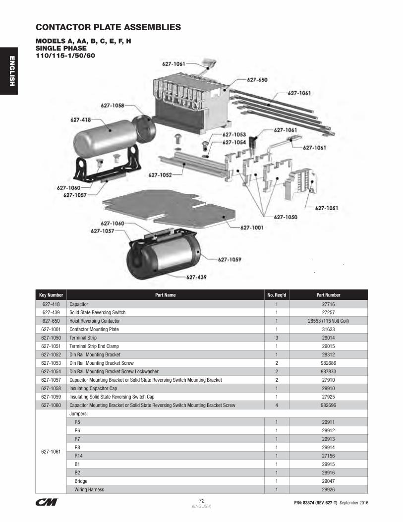
72 P/N: 83874 (REV. 627-T) September 2016(ENGLISH)
EN
GLIS
H
CONTACTOR PLATE ASSEMBLIES
MODELS A, AA, B, C, E, F, H SINGLE PHASE 110/115-1/50/60
Key Number Part Name No. Req'd Part Number
627-418 Capacitor 1 27716
627-439 Solid State Reversing Switch 1 27257
627-650 Hoist Reversing Contactor 1 28553 (115 Volt Coil)
627-1001 Contactor Mounting Plate 1 31633
627-1050 Terminal Strip 3 29014
627-1051 Terminal Strip End Clamp 1 29015
627-1052 Din Rail Mounting Bracket 1 29312
627-1053 Din Rail Mounting Bracket Screw 2 982686
627-1054 Din Rail Mounting Bracket Screw Lockwasher 2 987873
627-1057 Capacitor Mounting Bracket or Solid State Reversing Switch Mounting Bracket 2 27910
627-1058 Insulating Capacitor Cap 1 29910
627-1059 Insulating Solid State Reversing Switch Cap 1 27925
627-1060 Capacitor Mounting Bracket or Solid State Reversing Switch Mounting Bracket Screw 4 982696
627-1061
Jumpers:
R5 1 29911
R6 1 29912
R7 1 29913
R8 1 29914
R14 1 27156
B1 1 29915
B2 1 29916
Bridge 1 29047
Wiring Harness 1 29926
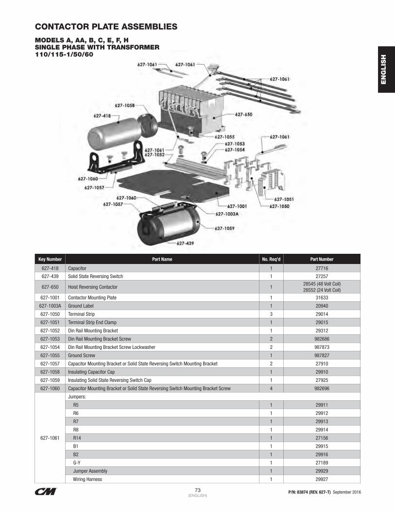
73 P/N: 83874 (REV. 627-T) September 2016(ENGLISH)
EN
GLIS
H
CONTACTOR PLATE ASSEMBLIES
MODELS A, AA, B, C, E, F, H SINGLE PHASE WITH TRANSFORMER 110/115-1/50/60
Key Number Part Name No. Req'd Part Number
627-418 Capacitor 1 27716
627-439 Solid State Reversing Switch 1 27257
627-650 Hoist Reversing Contactor 128545 (48 Volt Coil) 28552 (24 Volt Coil)
627-1001 Contactor Mounting Plate 1 31633
627-1003A Ground Label 1 20940
627-1050 Terminal Strip 3 29014
627-1051 Terminal Strip End Clamp 1 29015
627-1052 Din Rail Mounting Bracket 1 29312
627-1053 Din Rail Mounting Bracket Screw 2 982686
627-1054 Din Rail Mounting Bracket Screw Lockwasher 2 987873
627-1055 Ground Screw 1 987827
627-1057 Capacitor Mounting Bracket or Solid State Reversing Switch Mounting Bracket 2 27910
627-1058 Insulating Capacitor Cap 1 29910
627-1059 Insulating Solid State Reversing Switch Cap 1 27925
627-1060 Capacitor Mounting Bracket or Solid State Reversing Switch Mounting Bracket Screw 4 982696
627-1061
Jumpers:
R5 1 29911
R6 1 29912
R7 1 29913
R8 1 29914
R14 1 27156
B1 1 29915
B2 1 29916
G-Y 1 27189
Jumper Assembly 1 29929
Wiring Harness 1 29927

74 P/N: 83874 (REV. 627-T) September 2016(ENGLISH)
EN
GLIS
H
CONTACTOR PLATE ASSEMBLIES
MODELS A, AA, B, C, E, F, H SINGLE PHASE 220/230-1-50/60
Key Number Part Name No. Req'd Part Number
627-418 Capacitor 1 27716
627-439 Solid State Reversing Switch 1 27257
627-650 Hoist Reversing Contactor 128553 (110 Volt Coil) 28545 (48 Volt Coil) 28552 (24 Volt Coil)
627-1001 Contactor Mounting Plate 1 31633
627-1003A Ground Label 1 20940
627-1050 Terminal Strip 4 29014
627-1051 Terminal Strip End Clamp 1 29015
627-1052 Din Rail Mounting Bracket 1 29312
627-1053 Din Rail Mounting Bracket Screw 2 982686
627-1054 Din Rail Mounting Bracket Screw Lockwasher 2 987873
627-1055 Ground Screw 1 987827
627-1057 Capacitor Mounting Bracket or Solid State Reversing Switch Mounting Bracket 2 27910
627-1058 Insulating Capacitor Cap 1 29910
627-1059 Insulating Solid State Reversing Switch Cap 1 27925
627-1060 Capacitor Mounting Bracket or Solid State Reversing Switch Mounting Bracket Screw 4 982696
627-1061
Jumpers:
R5 1 29911
R6 1 29912
R7 1 29913
R8 1 29914
R14 1 27156
B1 1 29915
B2 1 29916
Bridge 1 27047
Contactor Jumper 1 51547
G-Y 1 27189
Wiring Harness 1 29928

75 P/N: 83874 (REV. 627-T) September 2016(ENGLISH)
EN
GLIS
H
CONTACTOR PLATE ASSEMBLIES
MODELS A, AA, B, C, E, F, H THREE PHASE, DUAL VOLTAGE 220/230-3-50/60 380/415/460-3-50/60
Key Number Part Name No. Req'd Part Number
627-650 Hoist Reversing Contactor 124799 (110 Volt Coil 24797 (48 Volt
Coil) 28860 (24 Volt Coil)
627-1001 Contactor Mounting Plate 1 31633
627-1003A Ground Label 1 20940
627-1012 Voltage Change Board Mounting Screw 1 987862
627-1013 Voltage Change Board 1 27672
627-1014 Voltage Change Board Insulator 1 27685
627-1050 Terminal Strip 1 29014
627-1051 Terminal Strip End Clamp 2 29015
627-1052 Din Rail Mounting Bracket 1 29312
627-1053 Din Rail Mounting Bracket Screw 2 982686
627-1054 Din Rail Mounting Bracket Screw Lockwasher 2 987873
627-1055 Ground Screw 1 987827
627-1061
Jumper:
G-Y 1 27189
Motor Wiring Harness 1 27603
Wiring Harness 1 29801
*627-1063 CM Terminal Pin Extraction Tool (Not Shown) 1 27163
* CM Terminal Pin Extraction Tool Can Be Ordered To Remove Individual Wires From Harness Connector.

76 P/N: 83874 (REV. 627-T) September 2016(ENGLISH)
EN
GLIS
H
CONTACTOR PLATE ASSEMBLIES
MODELS A-2, AA-2, B-2, C-2, E-2, F-2 & H-2 THREE PHASE, TWO SPEED 220/230-3-50/60, 380/415/460-3-50/60, 550/575-3-50/60
Key Number Part Name No. Req'd Part Number
627-650 Hoist Reversing Contactor 128553 (115 Volt Coil) 24797 (48 Volt Coil) 28860 (24 Volt Coil)
627-800 Hoist Speed Selecting Contactor 128870 (115 Volt Coil) 28871 (48 Volt Coil) 28878 (24 Volt Coil)
627-1001 Contactor Mounting Plate 1 31633
627-1003A Ground Label 1 20940
627-1050 Terminal Strip 1 29014
627-1051 Terminal Strip End Clamp 2 29015
627-1052 Din Rail Mounting Bracket 1 29312
627-1053 Din Rail Mounting Bracket Screw 2 982686
627-1054 Din Rail Mounting Bracket Screw Lockwasher 2 987873
627-1055 Ground Screw 1 987827
627-1061
Jumpers:
R10 1 27609
R13 1 27610
B1 1 29915
B2 1 29916
Contactor Jumper 2 51845
Contactor Jumper 2 51847
G-Y 1 27189
Wiring Harness 1 29802

77 P/N: 83874 (REV. 627-T) September 2016(ENGLISH)
EN
GLIS
H
CONTACTOR PLATE ASSEMBLIES
MODELS A, AA, B, B-2, C, E, F, H THREE PHASE 550/575-3-50/60
Key Number Part Name No. Req'd Part Number
627-650 Hoist Reversing Contactor 124799(115 Volt Coil) 24797 (48 Volt
Coil) 28860 (24 Volt Coil)
627-1001 Contactor Mounting Plate 1 31633
627-1003A Ground Label 1 20940
627-1050 Terminal Strip 1 29014
627-1051 Terminal Strip End Clamp 2 29015
627-1052 Din Rail Mounting Bracket 1 29312
627-1053 Din Rail Mounting Bracket Screw 2 982686
627-1054 Din Rail Mounting Bracket Screw Lockwasher 2 987873
627-1055 Ground Screw 1 987827
627-1061
Jumpers:
B1 1 29915
B2 1 29916
Contactor Jumper 1 51847
G-Y 1 27189
Wiring Harness 1 27160

78 P/N: 83874 (REV. 627-T) September 2016(ENGLISH)
EN
GLIS
H
CONTACTOR PLATE ASSEMBLIES
MODELS J, L, R & RT SINGLE PHASE 110/115-1-50/60
Key Number Part Name No. Req'd Part Number
627-418 Start Capacitor 1 35279
627-418A Run Capacitor 1 35278
627-423 Start/Run Capacitor Mounting Clamp 2 35268
627-424 Mounting Clamp Screw 6 982873
627-650 Hoist Reversing Contactor 1 27142 (115 Volt Coil) 27138 (48 Volt Coil) 27139 (24 Volt Coil)
627-1001 Contactor Mounting Plate 1 29013
627-1003A Ground Label 1 20940
627-1051 Terminal Strip End Clamp 2 29015
627-1052 Din Rail Mounting Bracket 1 29009
627-1053 Din Rail Mounting Bracket Screw 2 982686
627-1054 Din Rail Mounting Bracket Screw Lockwasher 2 987873
627-1061
Jumpers:
R2 1 29036
R3 1 29037
R4 1 29035
R5 1 29038
R10 1 29034
Contactor Jumper 1 51845
Wiring Harness 1 29039
627-1062 Rubber Insulating Boot 1 35285

79 P/N: 83874 (REV. 627-T) September 2016(ENGLISH)
EN
GLIS
H
CONTACTOR PLATE ASSEMBLIES
MODELS J, L, R & RT SINGLE PHASE 220/230-1-50/60
Key Number Part Name No. Req'd Part Number
627-418 Start Capacitor 1 35279
627-418A Run Capacitor 1 35278
627-423 Start/Run Capacitor Mounting Clamp 2 35268
627-424 Mounting Clamp Screw 6 982873
627-650 Hoist Reversing Contactor 127013 (115 Volt Coil) 27104 (48 Volt Coil) 27105 (24 Volt Coil)
627-1001 Contactor Mounting Plate 1 29013
627-1003A Ground Label 1 20940
627-1051 Terminal Strip End Clamp 2 29015
627-1052 Din Rail Mounting Bracket 1 29009
627-1053 Din Rail Mounting Bracket Screw 2 982686
627-1054 Din Rail Mounting Bracket Screw Lockwasher 2 987873
627-1061
Jumpers:
R2 1 29036
R3 1 29037
R4 1 29035
R5 1 29038
R9 1 29113
R10 1 29034
G-Y 1 27189
Wiring Harness 1 29044
627-1062 Rubber Insulating Boot 1 35285

80 P/N: 83874 (REV. 627-T) September 2016(ENGLISH)
EN
GLIS
H
* CM Terminal Pin Extraction Tool Can Be Ordered To Remove Individual Wires From Motor/Harness Connector.
CONTACTOR PLATE ASSEMBLIES
MODELS J, JJ, L, LL, R, RR, RT & RRT THREE PHASE, DUAL VOLTAGE 220/230-3-50/60, 380/415/460-3-50/60
Key Number Part Name No. Req'd Part Number
627-528 Transformer Mounting Screw 2 982688
627-530 Transformer 1
29734 (115 V Secondary) 29756 (48 V Secondary) 29809 (24 V Secondary)
29811 (115 V Secondary with Thermal Cutout) 29983 (48 V Secondary with Thermal Cutout) 29982 (24 V Secondary with Thermal Cutout)
627-650 Hoist Reversing Contactor 1 24799 (115 Volt Coil)
24797 (48 Volt Coil) 28860 (24 Volt Coil)
627-1001 Contactor Mounting Plate 1 29013
627-1003A Ground Label 1 20940
627-1012 Conversion Board Mounting Screw 1 987862
627-1013 Conversion Board 1 27672
627-1014 Conversion Board Insulator 1 27685
627-1050 Terminal Strip 3 29014
627-1051 Terminal Strip End Clamp 4 29015
627-1052
Din Rail Mounting Bracket
Contactor Bracket 1 29009
Terminal Strip Bracket 1 29008
627-1053 Din Rail Mounting Bracket Screw 4 982686
627-1054 Din Rail Mounting Bracket Screw Lockwasher 4 987873
627-1055 Ground Screw 1 987827
627-1061
Jumpers:
Contactor Jumper 1 51847
G-Y 1 27189
Wiring Harness 1 27102
Wiring Harness 1 29670
*627-1063 CM Terminal Pin Extraction Tool (Not Shown) 1 21763

81 P/N: 83874 (REV. 627-T) September 2016(ENGLISH)
EN
GLIS
H
CONTACTOR PLATE ASSEMBLIES
MODELS J-2, JJ-2, L-2, LL-2, R-2, RR-2, RT-2 & RRT-2 THREE PHASE, TWO SPEED 220/230-3-50/60
Key Number Part Name No. Req'd Part Number
627-528 Transformer Mounting Screw 2 982688
627-530 Transformer 1
29734 (115 V Secondary) 29756 (48 V Secondary) 29809 (24 V Secondary)
29811 (115 V Secondary with Thermal Cutout) 29983 (48 V Secondary with Thermal Cutout) 29982 (24 V Secondary with Thermal Cutout)
627-650 Hoist Reversing Contactor 1 24799 (115 Volt Coil)
24797 (48 Volt Coil) 28860 (24 Volt Coil)
627-800 Hoist Speed Selecting Contactor 1 28870 (115 Volt Coil)
28871 (48 Volt Coil) 28878 (24 volt Coil)
627-1001 Contactor Mounting Plate 1 29013
627-1003A Ground Label 1 20940
627-1050 Terminal Strip 3 29014
627-1051 Terminal Strip End Clamp 4 29015
627-1052
Din Rail Mounting Bracket
Contactor Bracket 1 29010
Terminal Strip Bracket 1 29008
627-1053 Din Rail Mounting Bracket Screw 4 982686
627-1054 Din Rail Mounting Bracket Screw Lockwasher 4 987873
627-1055 Ground Screw 1 987827
627-1061
Jumpers:
R4 1 27652
R5 1 27657
R7 1 27760
R8 1 27762
W5 1 27736
G-Y 1 27189
Speed Selector Jumper 2 51845
Wiring Harness 1 27897

82 P/N: 83874 (REV. 627-T) September 2016(ENGLISH)
EN
GLIS
H
CONTACTOR PLATE ASSEMBLIES
MODELS J-2, JJ-2, L-2, LL-2, R-2, RR-2, RT-2 & RRT-2 THREE PHASE, TWO SPEED 380/415/460-3-50/60
Key Number Part Name No. Req'd Part Number
627-528 Transformer Mounting Screw 2 982688
627-530 Transformer 1
29734 (115 V Secondary) 29756 (48 V Secondary) 29809 (24 V Secondary)
29811 (115 V Secondary with Thermal Cutout) 29983 (48 V Secondary with Thermal Cutout) 29982 (24 V Secondary with Thermal Cutout)
627-650 Hoist Reversing Contactor 1 24799 (115 Volt Coil)
24797 (48 Volt Coil) 28860 (24 Volt Coil)
627-800 Host Speed Selecting Contactor 1 28870 (115 Volt Coil)
28871 (48 Volt Coil) 28878 (24 Volt Coil)
627-1001 Contactor Mounting Plate 1 29013
627-1003A Ground Label 1 20940
627-1050 Terminal Strip 3 29014
627-1051 Terminal Strip End Clamp 4 29015
627-1052
Din Rail Mounting Bracket
Contactor Bracket 1 29010
Terminal Strip Bracket 1 29008
627-1053 Din Rail Mounting Bracket Screw 4 982686
627-1054 Din Rail Mounting Bracket Screw Lockwasher 4 987873
627-1055 Ground Screw 1 987827
627-1061
Jumpers:
R4 1 27652
R5 1 27657
W5 1 27736
G-Y 1 27189
Contactor Jumper 1 51847
Terminal Strip Jumper 1 51845
Speed Selector Jumper 2 51845
Wiring Harness 1 29600

83 P/N: 83874 (REV. 627-T) September 2016(ENGLISH)
EN
GLIS
H
CONTACTOR PLATE ASSEMBLIES
MODELS J, JJ, L, LL, R, RR, RT & RRT THREE PHASE, SINGLE SPEED 550/575-3-50/60
Key Number Part Name No. Req'd Part Number
627-528 Transformer Mounting Screw 2 982688
627-530 Transformer 1
29807 (115 V Secondary) 29805 (115 V Secondary with Thermal Cutout) 29789 (48 V Secondary with Thermal Cutout) 29984 (24 V Secondary with Thermal Cutout)
627-650 Hoist Reversing Contactor 1 24799 (115 Volt Coil)
24797 (48 Volt Coil) 28860 (24 Volt Coil)
627-1001 Contactor Mounting Plate 1 29013
627-1003A Ground Label 1 20940
627-1050 Terminal Strip 1 29014
627-1051 Terminal Strip End Clamp 4 29015
627-1052
Din Rail Mounting Bracket
Contactor Bracket 1 29009
Terminal Strip Bracket 1 29008
627-1053 Din Rail Mounting Bracket Screw 4 982686
627-1054 Din Rail Mounting Bracket Screw Lockwasher 4 987873
627-1055 Ground Screw 1 987827
627-1061
Jumpers:
Contactor Jumper 1 51847
G-Y 1 27189
Wiring Harness 1 29601
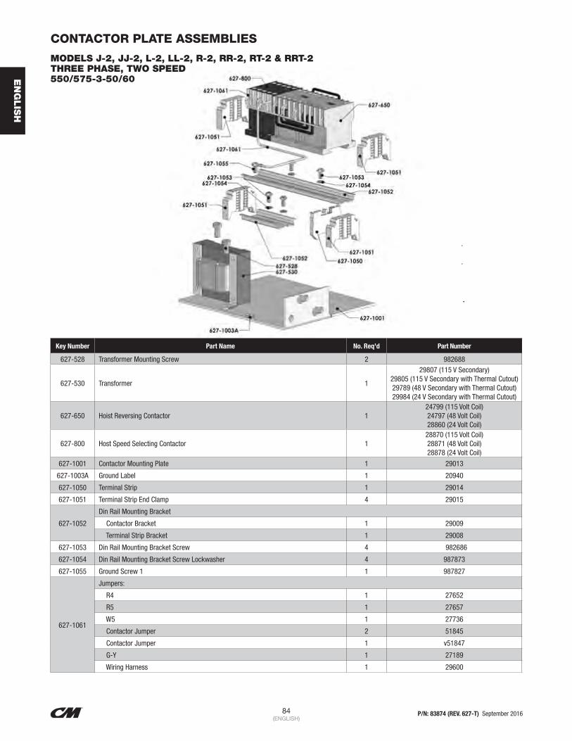
84 P/N: 83874 (REV. 627-T) September 2016(ENGLISH)
EN
GLIS
H
CONTACTOR PLATE ASSEMBLIES
MODELS J-2, JJ-2, L-2, LL-2, R-2, RR-2, RT-2 & RRT-2 THREE PHASE, TWO SPEED 550/575-3-50/60
Key Number Part Name No. Req'd Part Number
627-528 Transformer Mounting Screw 2 982688
627-530 Transformer 1
29807 (115 V Secondary) 29805 (115 V Secondary with Thermal Cutout) 29789 (48 V Secondary with Thermal Cutout) 29984 (24 V Secondary with Thermal Cutout)
627-650 Hoist Reversing Contactor 1 24799 (115 Volt Coil)
24797 (48 Volt Coil) 28860 (24 Volt Coil)
627-800 Host Speed Selecting Contactor 1 28870 (115 Volt Coil)
28871 (48 Volt Coil) 28878 (24 Volt Coil)
627-1001 Contactor Mounting Plate 1 29013
627-1003A Ground Label 1 20940
627-1050 Terminal Strip 1 29014
627-1051 Terminal Strip End Clamp 4 29015
627-1052
Din Rail Mounting Bracket
Contactor Bracket 1 29009
Terminal Strip Bracket 1 29008
627-1053 Din Rail Mounting Bracket Screw 4 982686
627-1054 Din Rail Mounting Bracket Screw Lockwasher 4 987873
627-1055 Ground Screw 1 1 987827
627-1061
Jumpers:
R4 1 27652
R5 1 27657
W5 1 27736
Contactor Jumper 2 51845
Contactor Jumper 1 v51847
G-Y 1 27189
Wiring Harness 1 29600

85 P/N: 83874 (REV. 627-T) September 2016(ENGLISH)
EN
GLIS
H
LODESTAR HOIST CONTROL STATION
627-450 COMPLETE CONTROL CORD AND STATION ASSEMBLY SINGLE SPEED HOIST CONTROL STATION
Key Number Part Name No. Req'd Part Number
627-450 Control Cord and Station Assembly 1
29333 for 10’ Lift 29334 for 15’ Lift 29335 for 20’ Lift
29336 for 10’ Lift for CSA Units
627-451 Standard Control Cord Assembly 1
29350 for 10’ Lift 29351 for 15’ Lift 29352 for 20’ Lift
29353 for 10’ Lift for CSA Units
627-551 Control Station Grommet 1 58278
627-552 Control Station (Includes 627-551 thru 627-567) 1 58272
627-563 Control Station Hardware Kit w/gasket 1 58275
627-565 Control Station 1-speed Insert 1 58255
627-566 Control Station Warning Label Kit (Includes Exterior Labels) 1 58276
627-567 Control Station Button Label Kit 1 58277

86 P/N: 83874 (REV. 627-T) September 2016(ENGLISH)
EN
GLIS
H
LODESTAR HOIST CONTROL STATION
627-450 COMPLETE CONTROL CORD AND STATION ASSEMBLY TWO SPEED HOIST CONTROL STATION
Key Number Part Name No. Req'd Part Number
627-450 Control Cord and Station Assembly 1 29337 for 10’ Lift
29348 for 10’ Lift for CSA Units
627-451 Standard Control Cord Assembly 1 29354 for 10’ Lift
29349 for 10’ Lift for CSA Units
627-551 Control Station Grommet 1 58278
627-552 Control Station (Includes 627-551 thru 627-567) 1 58273
627-563 Control Station Hardware Kit w/gasket 1 58275
627-565 Control Station 2-speed Insert 1 58256
627-566 Control Station Warning Label Kit (Includes Exterior Labels) 1 58276
627-567 Control Station Button Label Kit 1 58277

87 P/N: 83874 (REV. 627-T) September 2016(ENGLISH)
EN
GLIS
H
Key Number Part Name No. Req'd Part Number
627-451 Standard Control Cord Assembly 1 51708
627-551 Control Station Grommet 1 58278
627-552 Control Station (Includes 627-551 Thru 627-567) 1 58220 CM
627-553Control Station Housing Kit (Includes Housing, Boots, Collar, Gasket & Hardware)
1 58288
627-563 Control Station Hardware Kit w/gasket 1 58279
627-565Control Station 1-Speed Insert 1 58255
Control Station 2-Speed Insert 1 58256
627-566 Control Station Warning Label Kit 1 58276
627-567 Contol Station Button Label Kit 1 58277
LODESTAR HOIST CONTROL STATION
627-450 COMPLETE CONTROL CORD AND STATION ASSEMBLY FOUR DIRECTIONAL HOIST CONTROL STATION

88 P/N: 83874 (REV. 627-T) September 2016(ENGLISH)
EN
GLIS
H
Key Number Part Name
No. Req'd Part Number
1 Ton
2 Ton 1 Ton 2 Ton
627—330 TrackWheel 4 4 35774 50762
627—336 TrackWheel Stud Nut 4 4 982520 948804
627—337 Suspension Bolt (Special Alloy Special Alloy Steel Bolt)
*9 5/32” Long 2 — 35450 —
**10¼” Long 2 — 35407 —
†10” Long — 2 — 35445
††12 1/16” Long — 2 — 35414
627—338 Trolley Spacer Washers
* 0.165” Thick 40 — 35782 —
**0.125” Thick 38 — 958822 —
† 0.165” Thick — 32 — 35783
†† 0.125” Thick — 38 — 988039
627—339 Suspension Bolt Nut 4 4 948803 958818
627—340 Suspension Bolt Nut Cotter Pin
4 4 988343 988368
627—342 *** Side Frame, Plain Side,
w/o Trolley Guards2 2 35640 35654
*** Side Frame, Plain Side, Trolley Guards
2 2 35635 35636
627—379 *** Side Frame, I.D., Plate
Side, w/o Trolley Guards 2 2 35640 35654
*** Side Frame, I.D., Plate Side, Trolley Guards
2 2 35635 35636
SERIES 635 LOW HEADROOM TROLLEY PARTS LISTFigure 27. 1 and 2 Ton Series 635 Low Headroom Trolley Exploded View
Key Number Part Name
No. Req'd Part Number
1 Ton
2 Ton 1 Ton 2 Ton
627—380 Load Bracket
* 3 7/16” Wide 1 1 35019 —
**5 13/32” Wide 1 1 35024
† 4 3/16” Wide 1 1 — 35033
†† 6 11/16” Wide 1 1 — 35043
627—381 Vertical Load Bar Pin (Special Alloy Steel Pin)
*2 11/16” Long 1 1 35371 —
**2 7/8” Long 1 1 — 35413
†3 3/4” Long 1 1 — 35400
627—382 Vertical Load Bar Pin Screw
* ½” Long 1 1 982383 —
**1¼” Long 1 1 982386 —
† 3/4” Long 1 1 — 982433
†† 1½” Long 1 1 — 987209
627—383 Vertical Load Bar Pin Screw L.W.
1 1 983548 983547
627—384 TrackWheel Stud Nut L.W. 4 4 987923 987924
627—386 Identification Label 1 1 36916 36917
627—389 TrackWheel Washer — 1 — 987903
627—395 Warning Label 1 1 936984 936984
These items are for the 1-Ton Trolley for operation on 2.66" thru 5.64" flange widths. ** These items are for the 1-Ton Trolley for operation on over 5.64" thru 7.00" flange widths. *** If side frame is equipped with spacer block, contact factory. † These items are for the 2-Ton Trolley for operation on 3.33" thru 6.00" flange widths. †† These items are for the 2-Ton Trolley for operation on over 6.00" thru 8.25" flange widths.

89 P/N: 83874 (REV. 627-T) September 2016(ENGLISH)
EN
GLIS
H
SERIES 635 LOW HEADROOM TROLLEY PARTS LISTFigure 28. 3 Ton Series 635 Low Headroom Trolley Exploded View
Key Number Part Name No. Req'd Part Number
635-1 2 Side Frame-Plain Side (Does Not Include Wheels) 36696 For 4.0” Thru 5.63” Flange Widths, 36629 For Over 5.63” Thru 7-¼” Flange Widths. If Frame is Equipped With Trolley Guards, Contact
Factory.
635-4 4 TrackWheel Plain 39002
635-6 4 TrackWheel Bearing 82113
635-7 4 TrackWheel Stud 36361
635-9 4 TrackWheel Washer-Steel 81014
635-10 4 TrackWheel Washer-Oilite 82046
635-11 4 TrackWheel Stud Lockwasher 987926
635-12 4 TrackWheel Stud Nut 988155
635-13 1 Load Bracket (Specify Width) 36012 (4-13/16” Wide), 36021 (6-7/16” Wide)
635-17 2 Suspension Bolt (Specify Length) 36367 (10-31/32” Long) For 4.00” Thru 5.63” Flange Widths 36380 (13-3/32” Long) For Over 5.63” Thru 7.25” Flange Widths If Bolt
Length is Over 13-3/32”, Contact Factory
635-18 30 Spacer Washer 936827
635-19 4 Suspension Bolt Nut 945835
635-20 4 Suspension Bolt Cotter Pin 988382
635-22 1 Warning Label 936984
635-30 1 Identification Label 936829
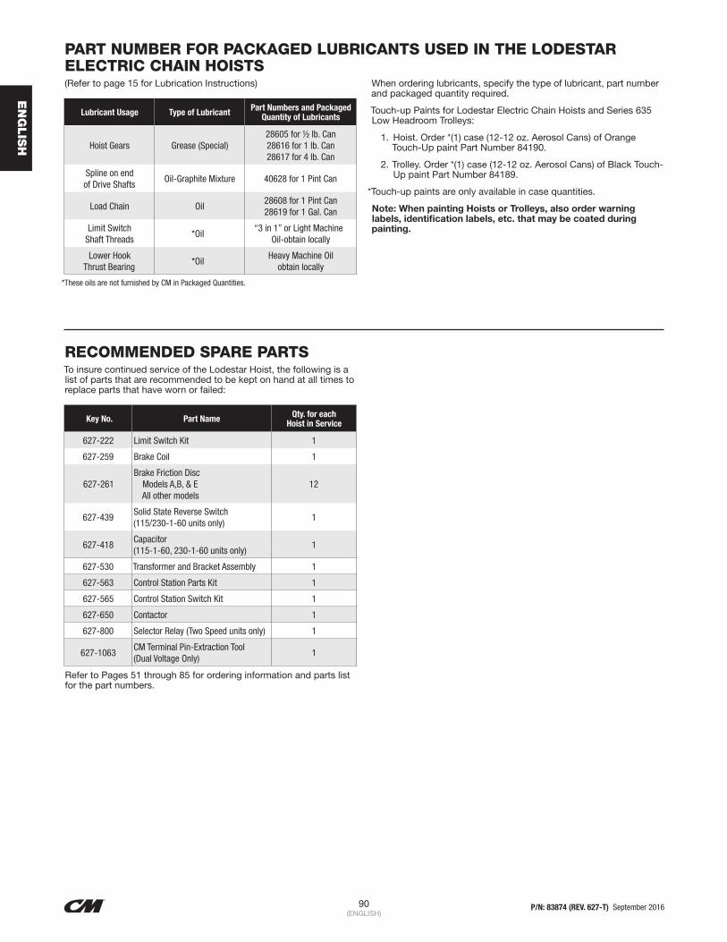
90 P/N: 83874 (REV. 627-T) September 2016(ENGLISH)
EN
GLIS
H
PART NUMBER FOR PACKAGED LUBRICANTS USED IN THE LODESTAR ELECTRIC CHAIN HOISTS(Refer to page 15 for Lubrication Instructions)
Lubricant Usage Type of Lubricant Part Numbers and Packaged Quantity of Lubricants
Hoist Gears Grease (Special)28605 for ½ lb. Can28616 for 1 lb. Can28617 for 4 lb. Can
Spline on end of Drive Shafts
Oil-Graphite Mixture 40628 for 1 Pint Can
Load Chain Oil28608 for 1 Pint Can28619 for 1 Gal. Can
Limit Switch Shaft Threads
*Oil“3 in 1” or Light Machine
Oil-obtain locally
Lower Hook Thrust Bearing
*OilHeavy Machine Oil
obtain locally
*These oils are not furnished by CM in Packaged Quantities.
When ordering lubricants, specify the type of lubricant, part number and packaged quantity required.
Touch-up Paints for Lodestar Electric Chain Hoists and Series 635 Low Headroom Trolleys:
1. Hoist. Order *(1) case (12-12 oz. Aerosol Cans) of Orange Touch-Up paint Part Number 84190.
2. Trolley. Order *(1) case (12-12 oz. Aerosol Cans) of Black Touch-Up paint Part Number 84189.
*Touch-up paints are only available in case quantities.
Note: When painting Hoists or Trolleys, also order warning labels, identification labels, etc. that may be coated during painting.
RECOMMENDED SPARE PARTSTo insure continued service of the Lodestar Hoist, the following is a list of parts that are recommended to be kept on hand at all times to replace parts that have worn or failed:
Key No. Part Name Qty. for each Hoist in Service
627-222 Limit Switch Kit 1
627-259 Brake Coil 1
627-261Brake Friction Disc Models A,B, & E All other models
12
627-439Solid State Reverse Switch (115/230-1-60 units only)
1
627-418Capacitor (115-1-60, 230-1-60 units only)
1
627-530 Transformer and Bracket Assembly 1
627-563 Control Station Parts Kit 1
627-565 Control Station Switch Kit 1
627-650 Contactor 1
627-800 Selector Relay (Two Speed units only) 1
627-1063CM Terminal Pin-Extraction Tool (Dual Voltage Only)
1
Refer to Pages 51 through 85 for ordering information and parts list for the part numbers.

91 P/N: 83874 (REV. 627-T) September 2016(ENGLISH)
EN
GLIS
H
NOTES

© 2016 Columbus McKinnon Corporation. All Rights Reserved.
USA: Ph: (800) 888.0985 • (716) 689.5400 • Fax: (716) 689.5644 • www.cmworks.comCANADA: Ph: (877) 264.6478 • Fax: (877) 264.6477 • www.cmworks.com