Embed Size (px)
Citation preview
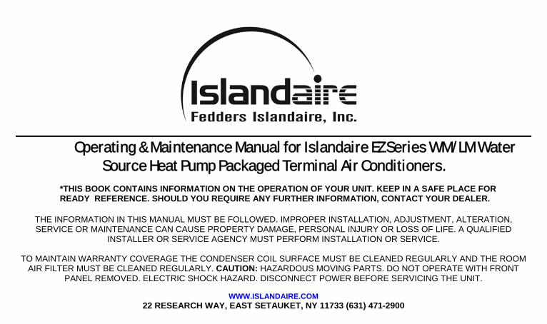
Operating & Maintenance Manual for Islandaire EZ Series WM/LM Water Source Heat Pump Packaged Terminal Air Conditioners.
*THIS BOOK CONTAINS INFORMATION ON THE OPERATION OF YOUR UNIT. KEEP IN A SAFE PLACE FOR READY REFERENCE. SHOULD YOU REQUIRE ANY FURTHER INFORMATION, CONTACT YOUR DEALER.
THE INFORMATION IN THIS MANUAL MUST BE FOLLOWED. IMPROPER INSTALLATION, ADJUSTMENT, ALTERATION, SERVICE OR MAINTENANCE CAN CAUSE PROPERTY DAMAGE, PERSONAL INJURY OR LOSS OF LIFE. A QUALIFIED
INSTALLER OR SERVICE AGENCY MUST PERFORM INSTALLATION OR SERVICE.
TO MAINTAIN WARRANTY COVERAGE THE CONDENSER COIL SURFACE MUST BE CLEANED REGULARLY AND THE ROOM AIR FILTER MUST BE CLEANED REGULARLY. CAUTION: HAZARDOUS MOVING PARTS. DO NOT OPERATE WITH FRONT
PANEL REMOVED. ELECTRIC SHOCK HAZARD. DISCONNECT POWER BEFORE SERVICING THE UNIT.
WWW.ISLANDAIRE.COM 22 RESEARCH WAY, EAST SETAUKET, NY 11733 (631) 471-2900
Table of Contents
Page
Contents Section
___ ___ ___ ___ ___ ___ ___ ___ ___
Water Source Heat Pumps Unit Specifications Installation Operating and Test Instructions Wiring Diagram and Servicing Replacement Parts List Warranty EZ Replacement Guide Troubleshooting Guide
___ ___ ___ ___ ___ ___ ___ ___ ___
RECEIVING UNITS
Upon receipt of equipment, check carton for visible damage. Make a notation on the shippers delivery ticket of any damages before signing. If there is any evidence of rough handling, the cartons should be opened at once to check for concealed damage. If any damage is found, notify the carrier within 48 hours to establish your claim and request an inspection report from the carrier. The warranty claims department should then be contacted.
Do not store or transport the unit on end. For proper storing, each carton is marked with “up” arrows. Upon receipt of this equipment, if you notice that the units were not stacked properly during transportation, make a notation on the shippers delivery ticket, and be sure the unit is in normal upright position 24 hours before operating.
In the event that elevator transfer makes up-ended positioning unavoidable, absolutely insure that the unit is in the normal upright position for at least 24 hours before operating. IGNORING THIS INSTRUCTION MAY VOID THE WARRANTY.
The units must be handled with care at all times. Rough handling can damage internal electrical and refrigeration components.
- 2 -

INSTALLATION CHECKLIST
The following instructions cover the installation of replacement PTAC units where existing wall sleeves are utilized. Instructions for the installation of a new wall sleeve are not covered in this manual. Installation and maintenance should be performed by qualified personnel who are familiar with local codes and regulations, and are experienced with this type of equipment.
All electrical connections and circuits must be installed in compliance with and conform to the
National Electrical Code (USA), Canadian Electrical Code (Canada) and local codes that have jurisdiction.
Inspect existing wall sleeve. (Refer to installation note 1; pg.4)
Ensure that supply air outlet is properly sealed to discharge of enclosure. (Refer to installation note 2; pg.4)
Electrical power is disconnected during installation or service.
Condenser air inlet and outlet MUST be clear and free of obstructions. (Refer to installation note 3; pg.4)
Condenser seals and baffles where applicable must be installed. (Refer to installation notes 4 & 5; pg.4)
Ensure that drapes, bed, bedspread, furniture, etc. DO NOT block either return or discharge air openings. (Refer to installation note 6; pg.5)
- 3 -

INSTALLATION NOTES 1– Inspect the existing wall sleeve to insure it is not damaged and that it is securely mounted in the wall. Use a level gauge to insure the sleeve is pitched properly. Be sure that any gaskets originally mounted on the wall sleeve that are missing or worn be replaced. 2- Any gaps between the discharge and the enclosure outlet will cause unit to short cycle. This condition will shorten compressor life. Small gaps should be sealed with foam rubber gaskets. Larger gaps may require a sheet metal collar (consult installing contractor). 3– A Packaged Thru Wall Air Conditioner must reject its heat to the outside air in the cooling mode. As a result, any obstruction that impedes this heat transfer will shorten compressor life. Warranty issues related to compressor failure as a result of these conditions will not be covered under warranty. 4– Thru-Wall units are shipped from the factory with foam rubber seals applied to the plate flanges of the condenser coil. The purpose of these seals is to fill the gap between the condenser coil and the outdoor louver. Unit must be slid completely into wall sleeve to insure proper seating of these seals. It is important that these seals remain intact during installation. Without these seals, compressor life may be shortened. Warranty issues related to compressor failure due to missing condenser coil seals will not be covered under warranty. 5– Certain installations with extended sleeves will require the use of baffles. These sheet metal baffles are attached to the condenser coil flange and have seals on their outer surface. These seals will seat against the outdoor grille when the unit is slid into an extended wall sleeve. It is important that units installed in extended wall sleeves have these baffles installed. Without these baffles, compressor life may be shortened. Warranty issues related to compressor failure due to missing condenser coil baffles will not be covered under warranty.
- 4 -
(Installation Notes, cont’d) 6– Ensure that there is adequate clearance for servicing and proper operation. A minimum of 18 inches in front of the chassis is required. Provide additional space for service technician to work on the unit. 7– Units must be installed in accordance with all applicable codes. 8– To prevent damage, this unit should NOT be operated to provide supplementary heating & cooling during the construction period. The unit is designed for operation in a normal indoor environment. Operating this unit in unenclosed space and exposure to construction environment may result in permanent damage. 9– Inspect the unit specification label in order to identify the model number. At this time voltage, capacity and other special features should be noted. 10– Be sure that the amperage of the dedicated electrical service to the unit is correct. Use of extension cord will void warranty. (Refer to table 1) 11– After unit is installed in sleeve, the shipping carton can be cut down and secured to unit to protect it during the construction phase.
- 5 -
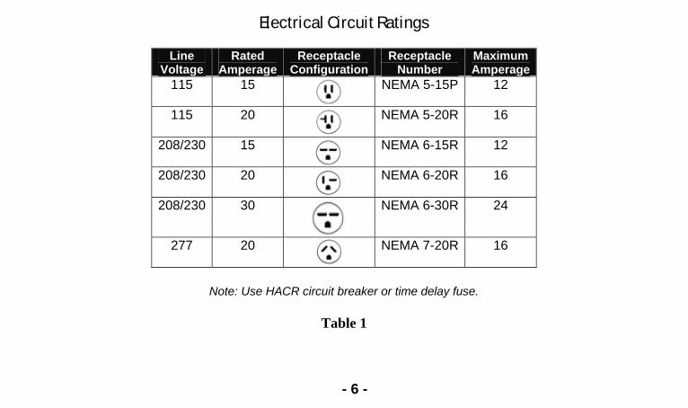
Electrical Circuit Ratings
Line Voltage
Rated Amperage
Receptacle Configuration
Receptacle Number
Maximum Amperage
115 15
NEMA 5-15P 12
115 20
NEMA 5-20R 16
208/230 15
NEMA 6-15R 12
208/230 20
NEMA 6-20R 16
208/230 30
NEMA 6-30R 24
277 20
NEMA 7-20R 16
Note: Use HACR circuit breaker or time delay fuse.
Table 1
- 6 -
OPERATING INSTRUCTIONS
This manual will describe the three types of control systems found on most Islandaire units:
1. Mechanical Pushbutton Switch (5 button) 2. Base Electronic Controls (keypad switch) 3. Intellitemp Electronic Controls (keypad switch)
Note: For operation of systems other than those referenced above consult installing contractor.
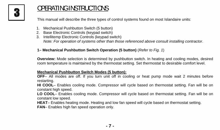
1– Mechanical Pushbutton Switch Operation (5 button) (Refer to Fig. 1)
Overview: Mode selection is determined by pushbutton switch. In heating and cooling modes, desired room temperature is maintained by the thermostat setting. Set thermostat to desirable comfort level.
Mechanical Pushbutton Switch Modes (5 button):OFF– All modes are off. If you turn unit off in cooling or heat pump mode wait 2 minutes before restarting. HI COOL– Enables cooling mode. Compressor will cycle based on thermostat setting. Fan will be on constant high speed. LO COOL– Enables cooling mode. Compressor will cycle based on thermostat setting. Fan will be on constant low speed. HEAT– Enables heating mode. Heating and low fan speed will cycle based on thermostat setting. FAN– Enables high fan speed operation only.
- 7 -
- 8 -
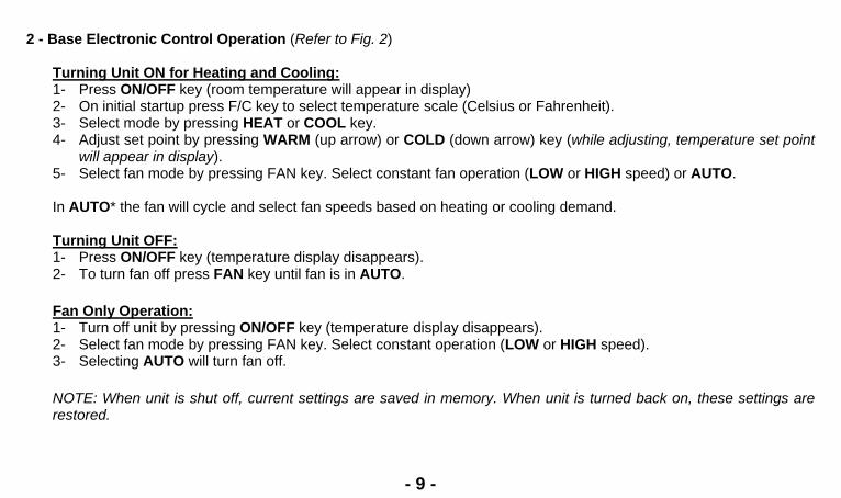
2 - Base Electronic Control Operation (Refer to Fig. 2)
Turning Unit ON for Heating and Cooling: 1- Press ON/OFF key (room temperature will appear in display) 2- On initial startup press F/C key to select temperature scale (Celsius or Fahrenheit). 3- Select mode by pressing HEAT or COOL key. 4- Adjust set point by pressing WARM (up arrow) or COLD (down arrow) key (while adjusting, temperature set point
will appear in display). 5- Select fan mode by pressing FAN key. Select constant fan operation (LOW or HIGH speed) or AUTO. In AUTO* the fan will cycle and select fan speeds based on heating or cooling demand.
Turning Unit OFF: 1- Press ON/OFF key (temperature display disappears). 2- To turn fan off press FAN key until fan is in AUTO.
Fan Only Operation: 1- Turn off unit by pressing ON/OFF key (temperature display disappears). 2- Select fan mode by pressing FAN key. Select constant operation (LOW or HIGH speed). 3- Selecting AUTO will turn fan off. NOTE: When unit is shut off, current settings are saved in memory. When unit is turned back on, these settings are restored.
- 9 -

- 10 -
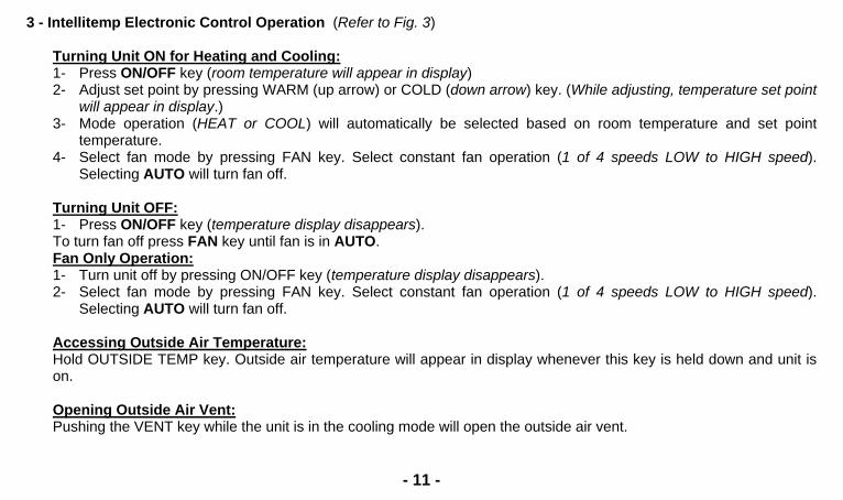
3 - Intellitemp Electronic Control Operation (Refer to Fig. 3)
Turning Unit ON for Heating and Cooling: 1- Press ON/OFF key (room temperature will appear in display) 2- Adjust set point by pressing WARM (up arrow) or COLD (down arrow) key. (While adjusting, temperature set point
will appear in display.) 3- Mode operation (HEAT or COOL) will automatically be selected based on room temperature and set point
temperature. 4- Select fan mode by pressing FAN key. Select constant fan operation (1 of 4 speeds LOW to HIGH speed).
Selecting AUTO will turn fan off.
Turning Unit OFF: 1- Press ON/OFF key (temperature display disappears). To turn fan off press FAN key until fan is in AUTO. Fan Only Operation: 1- Turn unit off by pressing ON/OFF key (temperature display disappears). 2- Select fan mode by pressing FAN key. Select constant fan operation (1 of 4 speeds LOW to HIGH speed).
Selecting AUTO will turn fan off. Accessing Outside Air Temperature: Hold OUTSIDE TEMP key. Outside air temperature will appear in display whenever this key is held down and unit is on. Opening Outside Air Vent: Pushing the VENT key while the unit is in the cooling mode will open the outside air vent.
- 11 -

Fig 3
NOTE: When unit is shut off, current settings are saved in memory. When unit is turned back on, these settings are restored.
- 12 -

Intellitemp Mode Selection On the Intellitemp control, the mode of operation (cool, heat or auto) may be selected by the user by pressing and holding the VENT and ON/OFF keys simultaneously. The display will scroll through the modes described below. When the desired mode is in the display, release the keys and that mode will be locked in. In AU (auto) the control will automatically cycle between either heating or cooling to maintain set point temperature.
- 13 -
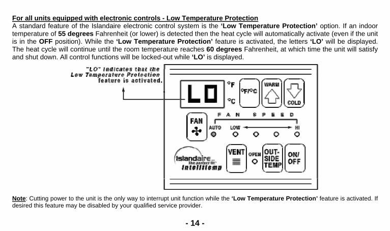
For all units equipped with electronic controls - Low Temperature Protection A standard feature of the Islandaire electronic control system is the ‘Low Temperature Protection’ option. If an indoor temperature of 55 degrees Fahrenheit (or lower) is detected then the heat cycle will automatically activate (even if the unit is in the OFF position). While the ‘Low Temperature Protection’ feature is activated, the letters ‘LO’ will be displayed. The heat cycle will continue until the room temperature reaches 60 degrees Fahrenheit, at which time the unit will satisfy and shut down. All control functions will be locked-out while ‘LO’ is displayed.
Note: Cutting power to the unit is the only way to interrupt unit function while the ‘Low Temperature Protection’ feature is activated. If desired this feature may be disabled by your qualified service provider.
- 14 -
ELECTRONIC BOARD DIAGNOSIS/TEST (Base or Intellitemp) Each unit has two ‘built-in’ tools to assist the technician in the trouble shooting of the entire system. The first tool is the ‘Continuous System Diagnostics’, and the second tool is the ‘Automatic System Component Test’.
1- Continuous System Diagnostics: The control incorporates continuous self-diagnostic checking of several system parameters and reports the status by an LED blink code on the main board.
1- Un-plug or disconnect the power to the unit. 2- Gain access into the electric box on the chassis and locate the main board within. 3- Locate the LED labeled ‘DIAGNOSTIC STATUS’ on the main board, near the center of the board. 4- Reapply power to the unit, wait approximately 10 seconds and the unit will enter its normal operating
mode. At this time the diagnostic indicator LED will blink repeatedly. These ‘blink codes’ will repeat approximately every 5 seconds with a delay between bursts and are readable as follows:
a. 0 blinks = no power b. 1 blink = normal c. 2 blinks = IAT (indoor air temperature) probe failure (check connection – replace) d. 3 blinks = OAT (outdoor air temperature) probe failure (check connection – replace) e. 4 blinks = Between board communications failure f. 5 blinks = Keypad failure (stuck key) or interconnect & ribbon cable failure g. 6 blinks = Remote thermostat input failure (bad input combination) check thermostat wiring. h. 7 blinks = Inadequate ground i. 8 blinks = Outdoor coil low temperature switch open (only if Heat Pump configured by DIP switch) –
disables compressor operation.
- 15 -

(Cont’d…) j. 9 blinks = Fan-limit switch open (only if Hydronic heat or gas heat configured by DIP switch) – Disables fan in gas heat mode and Hydronic heat mode. k. 10 blinks = Configuration read failure (check setting on configuration switch). l. 11 blinks = Module mismatch error (happens if boards are mismatched).
2- Automatic System Component Test: (to be performed only by a qualified service technician) 1- Un-plug or disconnect power to the unit. 2- Gain access to the electric box with the main board mounted within. Locate the 9-pin connector labeled EXPANSION on the main board. Pin #1 is located closest to the smaller connecter labeled IAT. (Refer to Fig. 6)
Fig. 6 - 16 -
3- Place a jumper between pin #6 and pin #9 of the EXPANSION connector. 4- Be sure any wires or parts moved during installation of jumper will not cause an electrical short. 5- Reapply power to the unit and wait approximately 20 seconds and the unit will enter an automatic system
component test sequence. The system automatically runs through the operational functions of each component within the unit. If the unit is equipped with a display, an abbreviated description of each function will be displayed (display is where temperature and set points are viewed) as each function is tested. Table (2) describes the abbreviated descriptions that are displayed and unit operation. Only functions available to the unit will be tested others will simply be ignored. This allows the technician to get a quick glimpse of whether the compressor, motor, speed or heating components function properly during the automatic test function, service efforts can be directed to the various controls that operate the system.
6- Un-plug or disconnect power to the unit. 7- Remove the jumper that was installed on pins #6 and #9 of the expansion connector. 8- Reapply power to unit to resume normal operation.
- 17 -
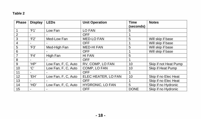
Table 2
Phase Display LEDs Unit Operation Time (seconds)
Notes
1 ‘F1’ Low Fan LO FAN 5 2 - - OFF 1 3 ‘F2’ Med-Low Fan MED-LO FAN 5 Will skip if base 4 - - OFF 1 Will skip if base 5 ‘F3’ Med-High Fan MED-HI FAN 5 Will skip if base 6 - OFF 1 Will skip if base 7 ‘F4’ High Fan HI FAN 5 8 - - OFF 1 9 ‘HP’ Low Fan, F, C, Auto RV, COMP, LO FAN 10 Skip if not Heat Pump 10 ‘C’ Low Fan, F, C, Auto COMP, LO FAN 10 Skip if Heat Pump 11 - - OFF 1 12 ‘EH’ Low Fan, F, C, Auto ELEC HEATER, LO FAN 10 Skip if no Elec Heat 13 - - OFF 1 Skip if no Elec Heat 14 ‘HD’ Low Fan, F, C, Auto HYDRONIC, LO FAN 5 Skip if no Hydronic 15 - - OFF DONE Skip if no Hydronic
- 18 -
HEAT PUMP UNITS
A heat pump operates by reversing the refrigeration cycle, absorbing heat from the outside air and transferring this heat to the indoor air. The heat output of the heat pump reduces as outdoor temperature drops. As a result, the discharge air temperature may not be sufficiently warm to provide heating comfort in certain locations. In these locations, an optional backup heater may be required. If the outdoor temperature drops low enough, the compressor (heat pump) will lock out entirely.
Activating Emergency or Backup Heat Operation (Heat Pump Units with mechanical pushbutton) On units with mechanical pushbutton controls, the backup unit mounted heater (if available) may be enabled manually through the backup heat switch. Turn off power to unit. Depending on the model, it may be necessary to remove the front panel to gain access to the emergency heat switch. To activate backup heater, push the switch to the ON position. Re-power the unit and select the heat mode. When backup heater function is no longer required, be sure to reset switch to enable cooling.
- 19 -

STARTUP CHECKLIST Note: Units are to be installed and checked for proper function by qualified service personnel ONLY.
Check the following:
Unit is installed in compliance with all codes
and ordinances. Circuit breakers and receptacles are
correct. Filter clean and in place.
All panels in place.
Condenser coil inlet and outlet free of obstructions, and is sealed to louver.
Unit is properly sealed in sleeve.
Evaporator air inlet & outlet is free from obstructions and properly sealed.
Smoke and odor can occur on initial use of the heating element due to processing residue and/or oil on the element. Leave the area serviced by the unit until it is ventilated of the smoke and odor by opening doors and windows.
Control operation OK.
Owner or operator instructed on control operation and routine maintenance.
Work area clean and free of debris.
Operate unit 20 minutes.
- 20 -
ROUTINE MAINTENANCE
• Keep air intake filter clean. A dirty filter reduces the efficiency of the system and can cause erratic performance of controls. It can also result in damage to the heating element and compressor. The unit is provided with a washable filter that can be cleaned with soap and water. Inspect and clean the filter at least once a month or more often as conditions dictate. Replace as necessary with a factory approved filter.
• Coils should be inspected periodically for build-up of lint, dirt, leaves, other debris and bent fins.
Clean coils with soft brush and compressed air or vacuum. Do NOT use sharp objects to clean coils.
• The fan motors are permanently lubricated and do not require re-oiling.
• In areas of heavy snow and ice accumulation, snow and ice should not be permitted to accumulate
against the unit. As soon as practical after such inclement weather, clean snow and ice from around the unit as much as possible from the filters of the unit.
• If unit is installed over the winter, be sure that the fan turns freely before turning it on.
- 21 -
OPERATIONAL PRACTICES
• Do not block airflow. Efficient operation of the unit depends on free circulation of air over the coils. Paper, leaves and other debris can reduce efficiency and cause serious damage to the compressor.
• Ensure that objects such as drapes, furniture or plants are not blocking supply and return airflow.
• Do NOT operate unit with front panel removed or without filter, as this will void any warranties.
• Keep doors and windows closed. Leaving them open will increase the workload on the unit and will
result in higher operating cost and excessive condensate.
• Do NOT operate unit during construction. Construction dust can clog filter and cause permanent damage to other components.
• On the mechanical pushbutton units with unit in cooling mode, if the unit is switched off wait at least
three minutes before switching the unit back on to avoid cycling the compressor.
- 22 -
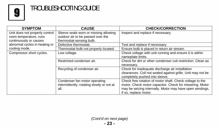
TROUBLESHOOTING GUIDE
SYMPTOM CAUSE CHECK/CORRECTION
Sleeve seals worn or missing allowing outdoor air to be passed over the thermostat-sensing bulb.
Inspect and replace if necessary.
Defective thermostat. Test and replace if necessary.
Unit does not properly control room temperature, runs continuously or causes abnormal cycles in heating or cooling mode. Thermostat bulb not properly located. Ensure bulb is placed in return air stream.
Low voltage. Check voltage with unit running and ensure it is within nameplate limits.
Restricted condenser air. Check for dirt or other condenser coil restriction. Clean as necessary.
Recycling of condenser air. Check for inadequate discharge air installation clearances. Coil not sealed against grille. Unit may not be completely pushed into sleeve.
Compressor short cycles.
Condenser fan motor operating intermittently, rotating slowly or not at all.
Check free rotation of motor shaft. Check voltage to the motor. Check motor capacitor. Check for miswiring. Motor may be seizing internally. Motor may have open windings, if so, replace motor.
(Cont’d on next page) - 23 -

TROUBLESHOOTING GUIDE (CONTINUED)
SYMPTOM CAUSE CHECK/CORRECTION Thermostat bulb or thermister is not properly located.
Ensure bulb is located at original factory specified location. (In return air)
Faulty or incorrect compressor overload.
Check for correct overload model number and replace if incorrect. Otherwise, if running amps seem normal, replace overload.
Indoor coil freezing. See “Evaporator Coil Frosts”. Recycling of indoor air. Ensure that curtains or other obstructions are not short
circuiting air between the outlet grille and return air intake.
Compressor short cycles (continued)
Compressor running too slow and drawing high amps.
Compressor may be miswired. Check capacitor. Compressor may be seizing – if so, replace compressor.
Fuse or circuit breaker tripped. Replace or re-test as necessary. Defective switch. Test and replace if necessary. Defective thermostat. Test and replace if necessary. Indoor room temperature below thermostat set point.
Lower thermostat setting if comfort not yet achieved.
Indoor room temperature below 65 degrees F.
Cooling will not operate if the room temperature is below 65 degrees F.
Compressor will not run.
Outdoor temperature too cold. Compressor is not intended to operate at cold outdoor temperatures (below 35 degrees F).
(Cont’d on next page) - 24 -

TROUBLESHOOTING GUIDE (CONTINUED)
SYMPTOM CAUSE CHECK/CORRECTION Broken, shorted, loose or miswired wiring.
Inspect and correct.
Defective compressor capacitor. Test and replace if necessary. Defective compressor overload. Test and replace if necessary. Low voltage or no voltage to compressor.
Check voltage and ensure that it is within nameplate limits.
Compressor windings open. Disconnect overload from compressor terminals. Check for winding resistance across all winding pairs C-S, C-R, S-R and check each terminal to the compressor shell for ground faults. Replace compressor if any windings are open-circuited or short circuited to the shell.
Compressor will not run (continued)
Seized compressor. If all of the above check out OK and if pressures are equalized and compressor draws high amps and will not start, compressor is seized and needs to be replaced.
Shorted or incorrect wiring. Check all connections. Also, check for shorts within devices such as motors, switches, heater, etc…
Shorted capacitor. Test and replace if necessary. Compressor short cycling. See “Compressor Short Cycles”.
Unit trips fuse / circuit breaker
Power was interrupted to the unit. Wait three minutes before restarting.
(Cont’d on next page) - 25 -
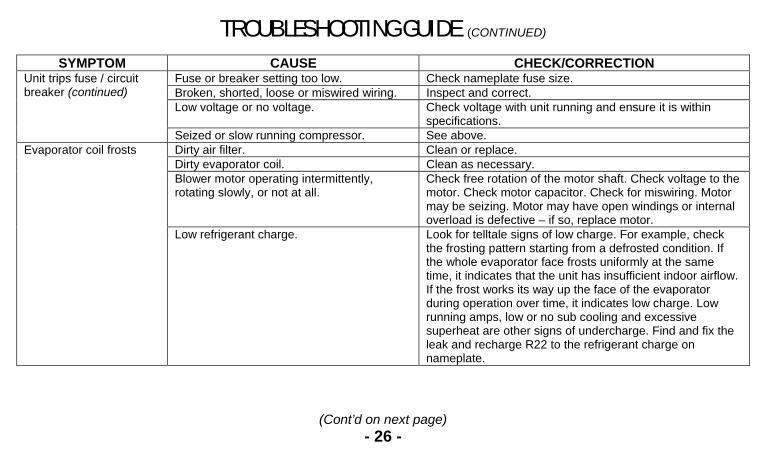
TROUBLESHOOTING GUIDE (CONTINUED)
SYMPTOM CAUSE CHECK/CORRECTION Fuse or breaker setting too low. Check nameplate fuse size. Broken, shorted, loose or miswired wiring. Inspect and correct. Low voltage or no voltage. Check voltage with unit running and ensure it is within
specifications.
Unit trips fuse / circuit breaker (continued)
Seized or slow running compressor. See above. Dirty air filter. Clean or replace. Dirty evaporator coil. Clean as necessary. Blower motor operating intermittently, rotating slowly, or not at all.
Check free rotation of the motor shaft. Check voltage to the motor. Check motor capacitor. Check for miswiring. Motor may be seizing. Motor may have open windings or internal overload is defective – if so, replace motor.
Evaporator coil frosts
Low refrigerant charge. Look for telltale signs of low charge. For example, check the frosting pattern starting from a defrosted condition. If the whole evaporator face frosts uniformly at the same time, it indicates that the unit has insufficient indoor airflow. If the frost works its way up the face of the evaporator during operation over time, it indicates low charge. Low running amps, low or no sub cooling and excessive superheat are other signs of undercharge. Find and fix the leak and recharge R22 to the refrigerant charge on nameplate.
(Cont’d on next page) - 26 -
TROUBLESHOOTING GUIDE (CONTINUED)
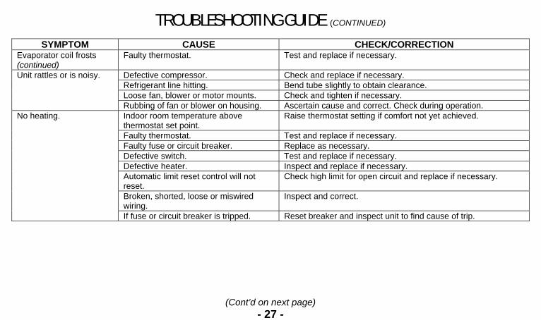
SYMPTOM CAUSE CHECK/CORRECTION Evaporator coil frosts (continued)
Faulty thermostat. Test and replace if necessary.
Defective compressor. Check and replace if necessary. Refrigerant line hitting. Bend tube slightly to obtain clearance. Loose fan, blower or motor mounts. Check and tighten if necessary.
Unit rattles or is noisy.
Rubbing of fan or blower on housing. Ascertain cause and correct. Check during operation. Indoor room temperature above thermostat set point.
Raise thermostat setting if comfort not yet achieved.
Faulty thermostat. Test and replace if necessary. Faulty fuse or circuit breaker. Replace as necessary. Defective switch. Test and replace if necessary. Defective heater. Inspect and replace if necessary. Automatic limit reset control will not reset.
Check high limit for open circuit and replace if necessary.
Broken, shorted, loose or miswired wiring.
Inspect and correct.
No heating.
If fuse or circuit breaker is tripped. Reset breaker and inspect unit to find cause of trip.
(Cont’d on next page) - 27 -
TROUBLESHOOTING GUIDE (CONTINUED)
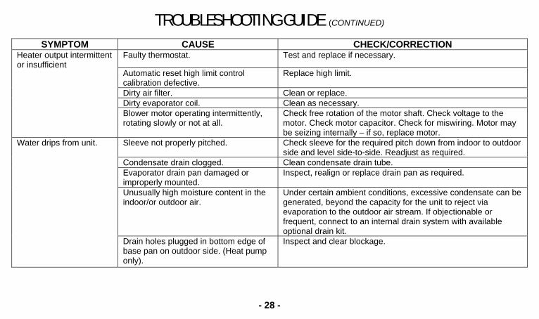
SYMPTOM CAUSE CHECK/CORRECTION Faulty thermostat. Test and replace if necessary.
Automatic reset high limit control calibration defective.
Replace high limit.
Dirty air filter. Clean or replace. Dirty evaporator coil. Clean as necessary.
Heater output intermittent or insufficient
Blower motor operating intermittently, rotating slowly or not at all.
Check free rotation of the motor shaft. Check voltage to the motor. Check motor capacitor. Check for miswiring. Motor may be seizing internally – if so, replace motor.
Sleeve not properly pitched. Check sleeve for the required pitch down from indoor to outdoor side and level side-to-side. Readjust as required.
Condensate drain clogged. Clean condensate drain tube. Evaporator drain pan damaged or improperly mounted.
Inspect, realign or replace drain pan as required.
Unusually high moisture content in the indoor/or outdoor air.
Under certain ambient conditions, excessive condensate can be generated, beyond the capacity for the unit to reject via evaporation to the outdoor air stream. If objectionable or frequent, connect to an internal drain system with available optional drain kit.
Water drips from unit.
Drain holes plugged in bottom edge of base pan on outdoor side. (Heat pump only).
Inspect and clear blockage.
- 28 -
Fill in information below Model # ____________________________________
Serial # _____________________________________
Part # _______________________________________
Date of Purchase _____________________________________
Installing Company _____________________________________
Telephone # _____________________________________

Return Material Authorization Procedure The following guidelines must be adhered to when returning units, parts and warranty parts to Islandaire, Inc.
1- Before returning parts, contact our Customer Service Department at 631-471-2900 to request a Return Material
Authorization (R.M.A.). When returning units, the model number and the serial number of the item(s) being returned is required along with a brief explanation of the reason for return.
2- For the return of parts, the R.M.A. is processed when replacement parts are ordered and is shipped with the replacement parts.
3- For Warranty parts, a UPS return label will be processed and sent with replacement parts order. This label must be affixed to the outside of the packaging. Contact UPS at 1-800-PICK-UPS (742-5877) to schedule the pickup or bring parts to any local UPS counter or pickup location. The Return Label provided must be used to return the parts it was intended for and cannot be used for any other return.
4- The defective parts must be returned to us within 30 days of the invoice date or credit will not be issued and the warranty invoice will become due and payable.
5- The R.M.A. paperwork must be included when the merchandise is returned and the yellow label provided must be affixed to the outside of the packaging. Should the R.M.A. paperwork be misplaced, please contact our Customer Service Department to generate a new copy, which can be faxed to you. Please be advised, any merchandise returned to Islandaire without R.M.A. paperwork will be refused and returned at the customers expense.
Questions regarding return procedure should be directed to the Customer Service Department.