Embed Size (px)
Citation preview
242 Inst Issue 3 07.09.2006
1
Operating & Maintenance Instructions 242 Vacuum Forming Machine Table of Contents 1. Introduction........................................................................................................................................... 2 2. Health & Safety Information ................................................................................................................. 4 3. Unpacking & Location .......................................................................................................................... 4 4. Electrical Supply & Connection............................................................................................................ 5 5. Pneumatic Supply & Connection ......................................................................................................... 6 6. Overview of Heater System ................................................................................................................. 7 7. Overview of Platen System.................................................................................................................. 8 8. Machine Controls ................................................................................................................................. 9 9. Initial Start-up ..................................................................................................................................... 10 10. Setting up Heaters - Basic Mode ...................................................................................................... 11 10. Setting up Heaters-Basic Mode (cont) .............................................................................................. 12 11. Setting up Heaters - Advanced Mode............................................................................................... 13 12. Setting up Timers .............................................................................................................................. 14 12. Setting up Timers (cont...)................................................................................................................. 15 13. Manual Mode .................................................................................................................................... 16 13. Manual Mode (cont…)....................................................................................................................... 17 14. Auto Mode......................................................................................................................................... 18 15. Configuration..................................................................................................................................... 19 16. Reducing Plates ................................................................................................................................ 21 17. Maintenance...................................................................................................................................... 22 18. Appendix 1 ........................................................................................................................................ 23
242 Inst Issue 3 07.09.2006
2
1. Introduction Your new 242 Vacuum Forming Machine has been designed to produce high quality vacuum formings on sheet sizes of up to 685mm x 660mm (27” x 26”), with a maximum moulding height of 300mm (11.8”). Changing the removable top plate, platen tray and clamp frame reduces the forming area. Reducing kits (Part No 242R) are available to order for this purpose. The material is heated from above by 40 ceramic heater elements. The heaters are separated into 15 heating zones, allowing the operator full control over heat distribution. The heater zones are controlled from the machine’s internal PLC (Programmable Logic Controller), and up to 40 different settings can be stored. The heater assembly slides on precision linear bearings to give smooth and maintenance-free service over many operations. Rodless pneumatic cylinders control the movement of the heater system. While heating, a through-beam sensor constantly checks the level of the sheet. As the material softens and drops under its own weight, air pressure from the vacuum / pressure pump is injected into the mould cavity, supporting the sheet to assist in obtaining uniform heating. Once heated, the heater system is moved to its rest position and the mould raised by a pair of pneumatic cylinders. Once the mould is in the raised position vacuum and release blow can be applied. A centrifugal fan blows cold air onto the moulding once it is formed to accelerate the cooling process. All of the movements of the machine are also controlled by the PLC, which can store up to 40 different timer settings. Timer settings can be entered individually. They can also be obtained by running the machine manually and copying the times into the PLC memory upon completion of the cycle. The operator is protected from moving parts by a light curtain across the front of the machine. This allows free access to the machine for material loading and adjustments. The machine operates on a 400V 3 phase electrical supply, and consumes 9kW of power on full load. A compressed air supply of 5-8 bar pressure is also required. The machine weighs 320kg and is mounted on heavy-duty castors for ease of location and movement.
242 Inst Issue 3 07.09.2006
3
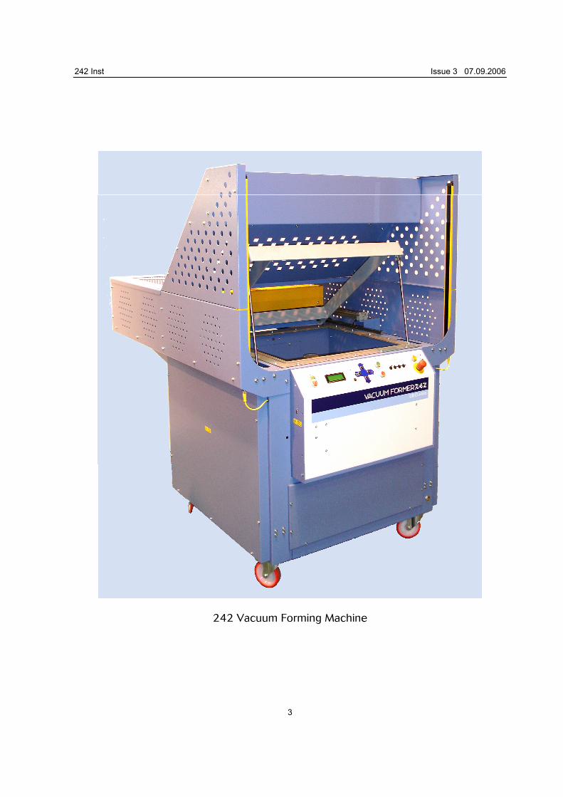
242 Vacuum Forming Machine
242 Inst Issue 3 07.09.2006
4
2. Health & Safety Information The 248 Vacuum Forming Machine utilises high power pneumatics to perform the forming process. Light guards are provided to prevent access to moving parts during operation. The machine must never be operated with these guards removed, damaged or malfunctioning in any way. In common with all vacuum forming machines, the material being heated on the 242 is clamped around its perimeter while heat is applied. Due to the expansion of the material, the centre may distort during heating prior to softening. When running the first component in a new material, care must be taken that the material does not rise and contact the heating elements. Failure to observe this point could result in ignition of the material. Should there be any specific queries regarding Health and Safety or any other aspects of the 242 Vacuum Forming machine please contact the manufacturer or their appointed local distributor.
3. Unpacking & Location Your 242 Vacuum Forming Machine will reach you complete and ready to use. Upon receipt proceed as follows: Unpack from wooden crate if necessary. Check for any signs of transit damage. All damages must be reported within 3 days of receipt. Position the machine as required. Should there be a need to lift the machine, use extended forks on a fork lift truck, ensuring that these extend underneath the machine and protrude through the opposite side. Ensure that the fork lift truck is capable of lifting the weight of the machine. Please note that the ends of the platen cylinders protrude beneath the base of the machine. Do not lift with the forks under the cylinders. Note that access to either side of the machine should be allowed for maintenance operations. Also, ensure that the meshed areas are not restricted in any way, as these allow excess heat to escape from the heater system. Lock the castors using the locking catches located on top of each wheel.
242 Inst Issue 3 07.09.2006
5
4. Electrical Supply & Connection The electrical specification of your new machine is as follows:- Voltage 400V 50Hz 3 Phase Current (max per Phase) 20A Watts (max) 9000W The colour coding of the wires in this appliance are as follows: L1 Red L2 Yellow L3 Blue Earth Yellow / Green It is recommended that the machine be supplied from a dedicated 400V 3 Phase + Earth, 20A per phase power supply. Phase Sequence The 242 Vacuum Forming Machine incorporates a 3 phase motor for the vacuum / pressure pump, and therefore phase sequence is important to ensure that it rotates in the correct direction. To check this, place the machine in Manual Mode and switch on the cooling fan. The fan should rotate in the direction of the arrow marked on the fan housing. To correct rotation, disconnect the machine from the mains supply, disconnect the blue and the yellow. Connect Blue to L2 and Yellow to L3. Retest. Should there be any queries regarding the electrical requirements of the 242 Vacuum Forming Machine please refer back to the manufacturer or their nominated distributor.
242 Inst Issue 3 07.09.2006
6
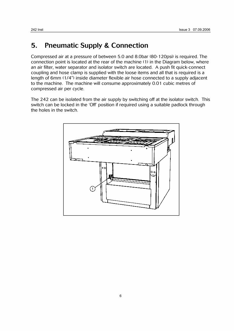
5. Pneumatic Supply & Connection Compressed air at a pressure of between 5.0 and 8.0bar (80-120psi) is required. The connection point is located at the rear of the machine (1) in the Diagram below, where an air filter, water separator and isolator switch are located. A push fit quick-connect coupling and hose clamp is supplied with the loose items and all that is required is a length of 6mm (1/4") inside diameter flexible air hose connected to a supply adjacent to the machine. The machine will consume approximately 0.01 cubic metres of compressed air per cycle. The 242 can be isolated from the air supply by switching off at the isolator switch. This switch can be locked in the ‘Off’ position if required using a suitable padlock through the holes in the switch.
242 Inst Issue 3 07.09.2006
7
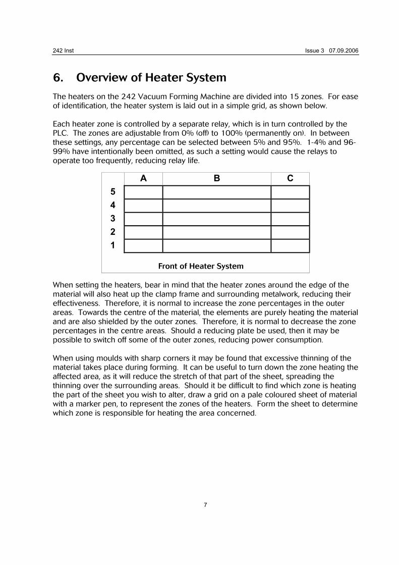
6. Overview of Heater System The heaters on the 242 Vacuum Forming Machine are divided into 15 zones. For ease of identification, the heater system is laid out in a simple grid, as shown below. Each heater zone is controlled by a separate relay, which is in turn controlled by the PLC. The zones are adjustable from 0% (off) to 100% (permanently on). In between these settings, any percentage can be selected between 5% and 95%. 1-4% and 96-99% have intentionally been omitted, as such a setting would cause the relays to operate too frequently, reducing relay life.
A B C 5
4
3
2
1
Front of Heater System
When setting the heaters, bear in mind that the heater zones around the edge of the material will also heat up the clamp frame and surrounding metalwork, reducing their effectiveness. Therefore, it is normal to increase the zone percentages in the outer areas. Towards the centre of the material, the elements are purely heating the material and are also shielded by the outer zones. Therefore, it is normal to decrease the zone percentages in the centre areas. Should a reducing plate be used, then it may be possible to switch off some of the outer zones, reducing power consumption. When using moulds with sharp corners it may be found that excessive thinning of the material takes place during forming. It can be useful to turn down the zone heating the affected area, as it will reduce the stretch of that part of the sheet, spreading the thinning over the surrounding areas. Should it be difficult to find which zone is heating the part of the sheet you wish to alter, draw a grid on a pale coloured sheet of material with a marker pen, to represent the zones of the heaters. Form the sheet to determine which zone is responsible for heating the area concerned.
242 Inst Issue 3 07.09.2006
8
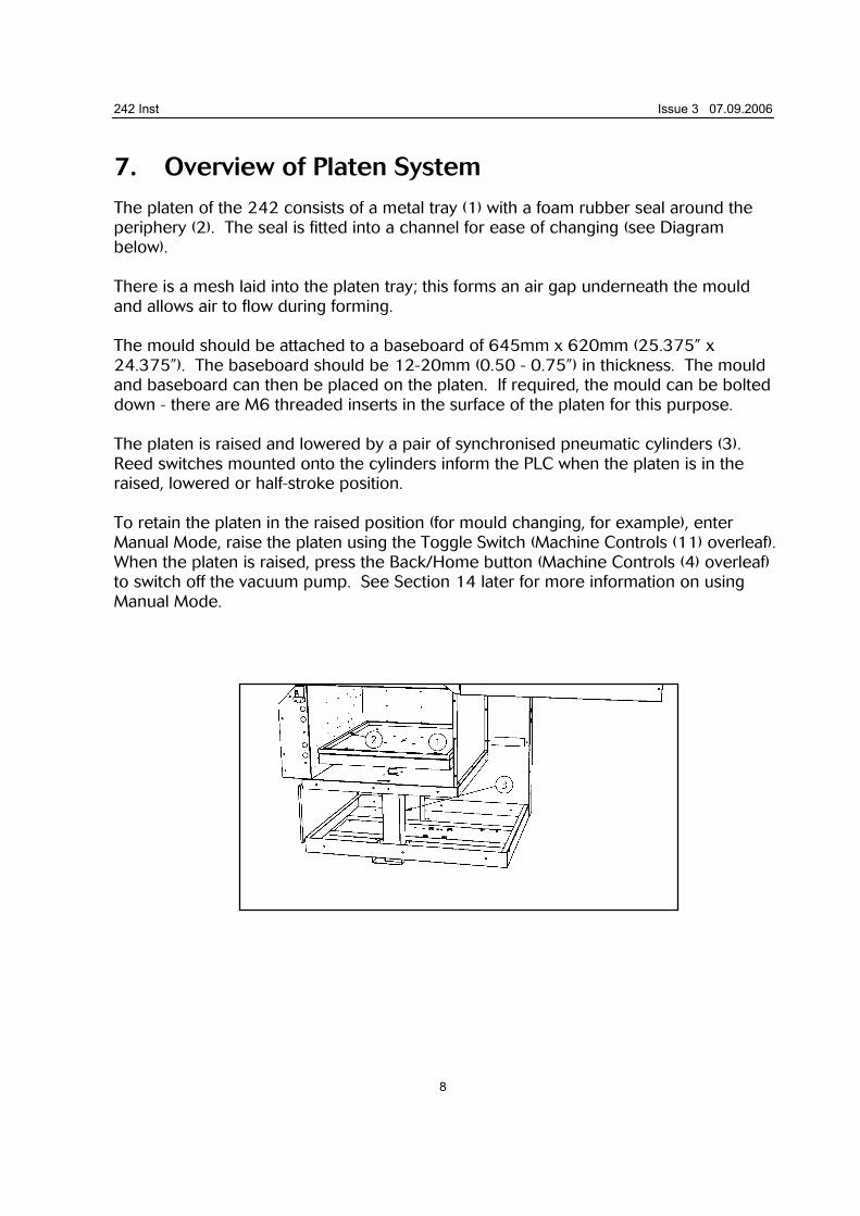
7. Overview of Platen System The platen of the 242 consists of a metal tray (1) with a foam rubber seal around the periphery (2). The seal is fitted into a channel for ease of changing (see Diagram below). There is a mesh laid into the platen tray; this forms an air gap underneath the mould and allows air to flow during forming. The mould should be attached to a baseboard of 645mm x 620mm (25.375” x 24.375”). The baseboard should be 12-20mm (0.50 - 0.75”) in thickness. The mould and baseboard can then be placed on the platen. If required, the mould can be bolted down - there are M6 threaded inserts in the surface of the platen for this purpose. The platen is raised and lowered by a pair of synchronised pneumatic cylinders (3). Reed switches mounted onto the cylinders inform the PLC when the platen is in the raised, lowered or half-stroke position. To retain the platen in the raised position (for mould changing, for example), enter Manual Mode, raise the platen using the Toggle Switch (Machine Controls (11) overleaf). When the platen is raised, press the Back/Home button (Machine Controls (4) overleaf) to switch off the vacuum pump. See Section 14 later for more information on using Manual Mode.
242 Inst Issue 3 07.09.2006
9
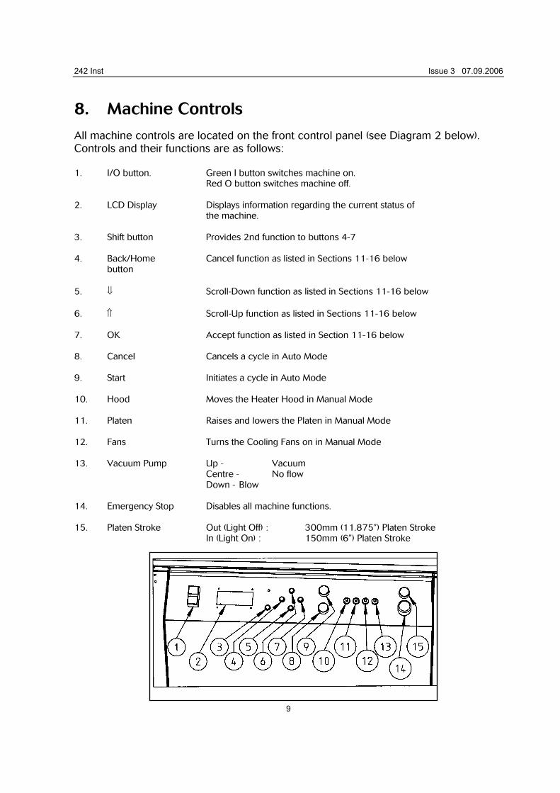
8. Machine Controls All machine controls are located on the front control panel (see Diagram 2 below). Controls and their functions are as follows: 1. I/O button. Green I button switches machine on. Red O button switches machine off. 2. LCD Display Displays information regarding the current status of the machine. 3. Shift button Provides 2nd function to buttons 4-7 4. Back/Home Cancel function as listed in Sections 11-16 below button 5. ⇓ Scroll-Down function as listed in Sections 11-16 below 6. ⇑ Scroll-Up function as listed in Sections 11-16 below 7. OK Accept function as listed in Section 11-16 below 8. Cancel Cancels a cycle in Auto Mode 9. Start Initiates a cycle in Auto Mode 10. Hood Moves the Heater Hood in Manual Mode 11. Platen Raises and lowers the Platen in Manual Mode 12. Fans Turns the Cooling Fans on in Manual Mode 13. Vacuum Pump Up - Vacuum Centre - No flow Down - Blow 14. Emergency Stop Disables all machine functions. 15. Platen Stroke Out (Light Off) : 300mm (11.875”) Platen Stroke In (Light On) : 150mm (6”) Platen Stroke
242 Inst Issue 3 07.09.2006
10
9. Initial Start-up Ensure that the machine is connected as detailed in Sections 4-6.
Operation LCD Display
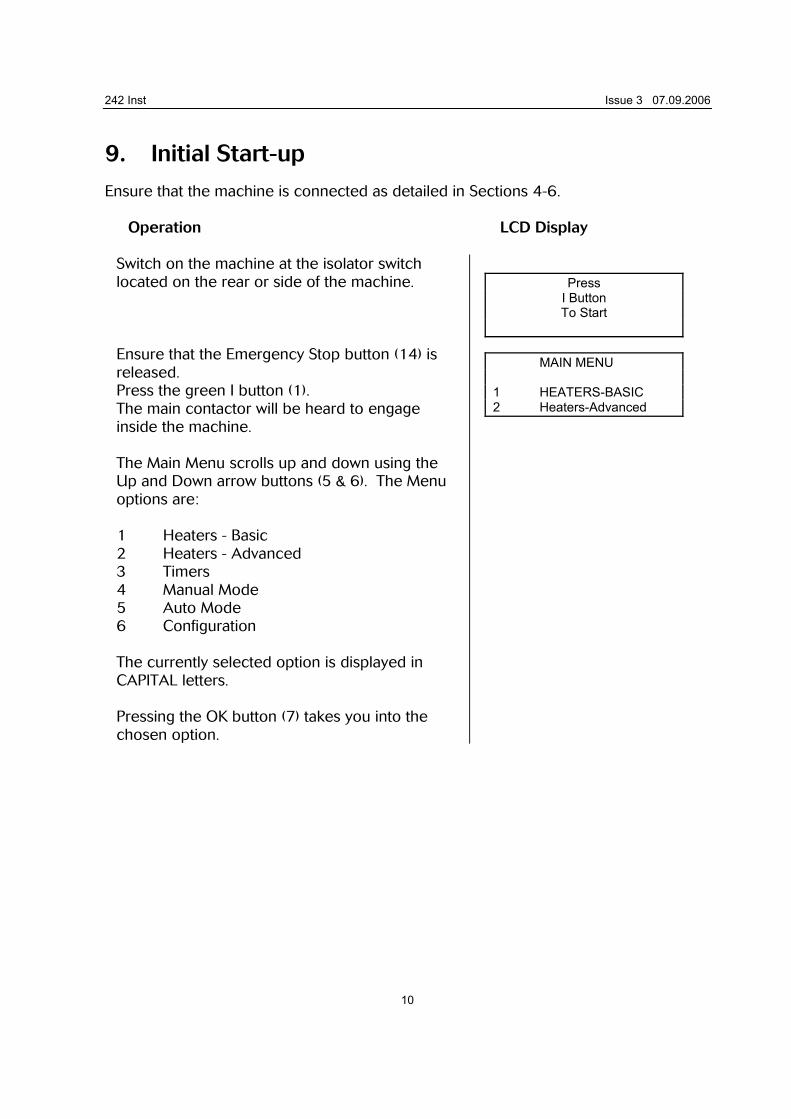
Switch on the machine at the isolator switch located on the rear or side of the machine. Ensure that the Emergency Stop button (14) is released. Press the green I button (1). The main contactor will be heard to engage inside the machine. The Main Menu scrolls up and down using the Up and Down arrow buttons (5 & 6). The Menu options are: 1 Heaters - Basic 2 Heaters - Advanced 3 Timers 4 Manual Mode 5 Auto Mode 6 Configuration The currently selected option is displayed in CAPITAL letters. Pressing the OK button (7) takes you into the chosen option.
Press
I Button To Start
MAIN MENU 1 HEATERS-BASIC 2 Heaters-Advanced
242 Inst Issue 3 07.09.2006
11
10. Setting up Heaters - Basic Mode
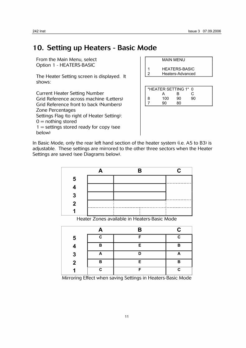
From the Main Menu, select Option 1 - HEATERS-BASIC The Heater Setting screen is displayed. It shows: Current Heater Setting Number Grid Reference across machine (Letters) Grid Reference front to back (Numbers) Zone Percentages Settings Flag (to right of Heater Setting): 0 = nothing stored 1 = settings stored ready for copy (see below)
MAIN MENU 1 HEATERS-BASIC 2 Heaters-Advanced *HEATER SETTING 1* 0 A B C 8 100 90 90 7 90 80
In Basic Mode, only the rear left hand section of the heater system (i.e. A5 to B3) is adjustable. These settings are mirrored to the other three sectors when the Heater Settings are saved (see Diagrams below).
A B C 5
4
3
2
1
Heater Zones available in Heaters-Basic Mode
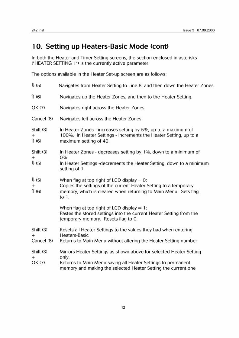
A B C 5 C F C
4 B E B
3 A D A
2 B E B
1 C F C
Mirroring Effect when saving Settings in Heaters-Basic Mode
242 Inst Issue 3 07.09.2006
12
10. Setting up Heaters-Basic Mode (cont) In both the Heater and Timer Setting screens, the section enclosed in asterisks (*HEATER SETTING 1*) is the currently active parameter. The options available in the Heater Set-up screen are as follows: ⇓ (5) Navigates from Heater Setting to Line 8, and then down the Heater Zones. ⇑ (6) Navigates up the Heater Zones, and then to the Heater Setting. OK (7) Navigates right across the Heater Zones Cancel (8) Navigates left across the Heater Zones Shift (3) In Heater Zones - increases setting by 5%, up to a maximum of + 100%. In Heater Settings - increments the Heater Setting, up to a ⇑ (6) maximum setting of 40. Shift (3) In Heater Zones - decreases setting by 1%, down to a minimum of + 0% ⇓ (5) In Heater Settings -decrements the Heater Setting, down to a minimum
setting of 1 ⇓ (5) When flag at top right of LCD display = 0: + Copies the settings of the current Heater Setting to a temporary ⇑ (6) memory, which is cleared when returning to Main Menu. Sets flag
to 1. When flag at top right of LCD display = 1:
Pastes the stored settings into the current Heater Setting from the temporary memory. Resets flag to 0.
Shift (3) Resets all Heater Settings to the values they had when entering + Heaters-Basic Cancel (8) Returns to Main Menu without altering the Heater Setting number Shift (3) Mirrors Heater Settings as shown above for selected Heater Setting + only. OK (7) Returns to Main Menu saving all Heater Settings to permanent
memory and making the selected Heater Setting the current one
242 Inst Issue 3 07.09.2006
13
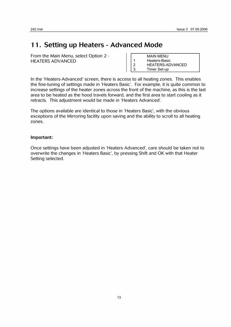
11. Setting up Heaters - Advanced Mode From the Main Menu, select Option 2 - HEATERS ADVANCED
MAIN MENU 1 Heaters-Basic 2 HEATERS-ADVANCED 3. Timer Set-up
In the ‘Heaters-Advanced’ screen, there is access to all heating zones. This enables the fine-tuning of settings made in ‘Heaters Basic’. For example, it is quite common to increase settings of the heater zones across the front of the machine, as this is the last area to be heated as the hood travels forward, and the first area to start cooling as it retracts. This adjustment would be made in ‘Heaters Advanced’. The options available are identical to those in ‘Heaters Basic’, with the obvious exceptions of the Mirroring facility upon saving and the ability to scroll to all heating zones. Important: Once settings have been adjusted in ‘Heaters Advanced’, care should be taken not to overwrite the changes in ‘Heaters Basic’, by pressing Shift and OK with that Heater Setting selected.
242 Inst Issue 3 07.09.2006
14
12. Setting up Timers
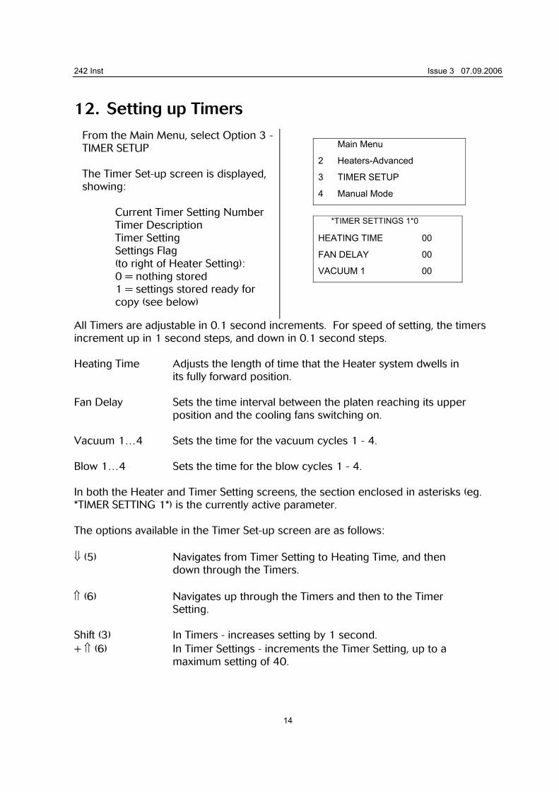
From the Main Menu, select Option 3 - TIMER SETUP The Timer Set-up screen is displayed, showing: Current Timer Setting Number Timer Description Timer Setting
Settings Flag (to right of Heater Setting):
0 = nothing stored 1 = settings stored ready for copy (see below)
Main Menu
2 Heaters-Advanced
3 TIMER SETUP
4 Manual Mode
*TIMER SETTINGS 1*0
HEATING TIME 00
FAN DELAY 00
VACUUM 1 00
All Timers are adjustable in 0.1 second increments. For speed of setting, the timers increment up in 1 second steps, and down in 0.1 second steps. Heating Time Adjusts the length of time that the Heater system dwells in
its fully forward position. Fan Delay Sets the time interval between the platen reaching its upper
position and the cooling fans switching on. Vacuum 1…4 Sets the time for the vacuum cycles 1 - 4. Blow 1…4 Sets the time for the blow cycles 1 - 4. In both the Heater and Timer Setting screens, the section enclosed in asterisks (eg. *TIMER SETTING 1*) is the currently active parameter. The options available in the Timer Set-up screen are as follows: ⇓ (5) Navigates from Timer Setting to Heating Time, and then
down through the Timers. ⇑ (6) Navigates up through the Timers and then to the Timer
Setting. Shift (3) In Timers - increases setting by 1 second. + ⇑ (6) In Timer Settings - increments the Timer Setting, up to a
maximum setting of 40.
242 Inst Issue 3 07.09.2006
15
12. Setting up Timers (cont...) Shift (3) + ⇓ (5)
In Timers - decreases setting by 0.1 second, down to a minimum of 0 seconds. In Timer Settings decrements the Timer Setting, down to a minimum setting of 1.
⇓ (5) + ⇑ (6)
When flag at top right of LCD display = 0: Copies the settings of the current Timer Setting to a temporary memory, which is cleared when returning to Main Menu. Sets flag to 1.
When flag at top right of LCD display = 1:
Pastes the stored settings into the current Timer Setting from the temporary memory. Resets flag to 0.
Shift (3) + Cancel (8)
Resets all Timer Settings to the values that they had when entering Timer Settings. Leaves the current Timer Setting number as it was when entering Timer Settings. Returns to Main Menu.
Shift (3) + OK (7)
Saves all Timer Settings to permanent memory. Makes the selected Timer Setting the current one. Returns to Main Menu.
To set up the machine from scratch is time-consuming and also includes a lot of guesswork. To eliminate this, there is a facility to paste settings from a Manual Cycle. For information on storing these settings into temporary memory see Section 14 later. To copy these settings into a Timer Setting, proceed as follows: Once the Timer Settings have been stored you will automatically enter the Timer Settings screen. The flag at the top right of the LCD display = 2, showing that manual times have been stored. Select the Timer Setting you wish to use (using Shift + ⇑/⇓) ⇓ (5) + ⇑ (6)
When flag at top right of LCD display = 2: Pastes the stored settings into the current Timer Setting from the temporary memory. Resets flag to 0.
242 Inst Issue 3 07.09.2006
16
13. Manual Mode
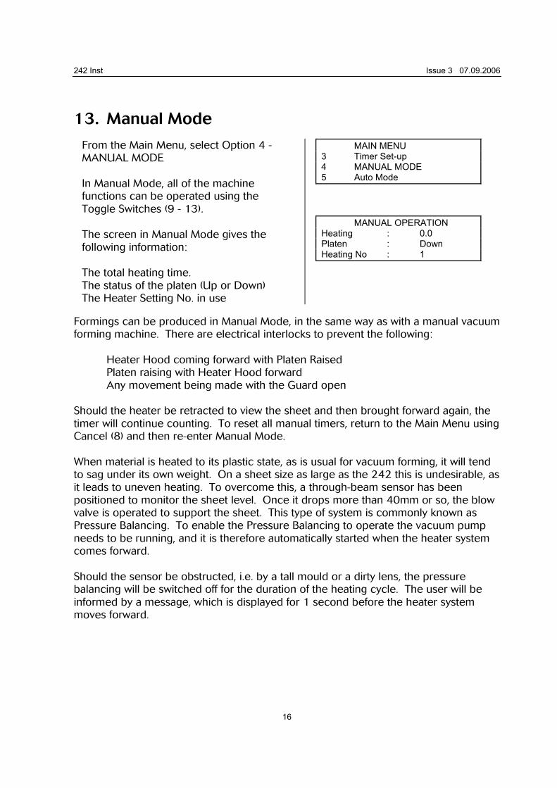
From the Main Menu, select Option 4 - MANUAL MODE In Manual Mode, all of the machine functions can be operated using the Toggle Switches (9 - 13). The screen in Manual Mode gives the following information: The total heating time. The status of the platen (Up or Down) The Heater Setting No. in use
MAIN MENU 3 Timer Set-up 4 MANUAL MODE 5 Auto Mode MANUAL OPERATION Heating : 0.0 Platen : Down Heating No : 1
Formings can be produced in Manual Mode, in the same way as with a manual vacuum forming machine. There are electrical interlocks to prevent the following:
Heater Hood coming forward with Platen Raised Platen raising with Heater Hood forward Any movement being made with the Guard open
Should the heater be retracted to view the sheet and then brought forward again, the timer will continue counting. To reset all manual timers, return to the Main Menu using Cancel (8) and then re-enter Manual Mode. When material is heated to its plastic state, as is usual for vacuum forming, it will tend to sag under its own weight. On a sheet size as large as the 242 this is undesirable, as it leads to uneven heating. To overcome this, a through-beam sensor has been positioned to monitor the sheet level. Once it drops more than 40mm or so, the blow valve is operated to support the sheet. This type of system is commonly known as Pressure Balancing. To enable the Pressure Balancing to operate the vacuum pump needs to be running, and it is therefore automatically started when the heater system comes forward. Should the sensor be obstructed, i.e. by a tall mould or a dirty lens, the pressure balancing will be switched off for the duration of the heating cycle. The user will be informed by a message, which is displayed for 1 second before the heater system moves forward.
242 Inst Issue 3 07.09.2006
17
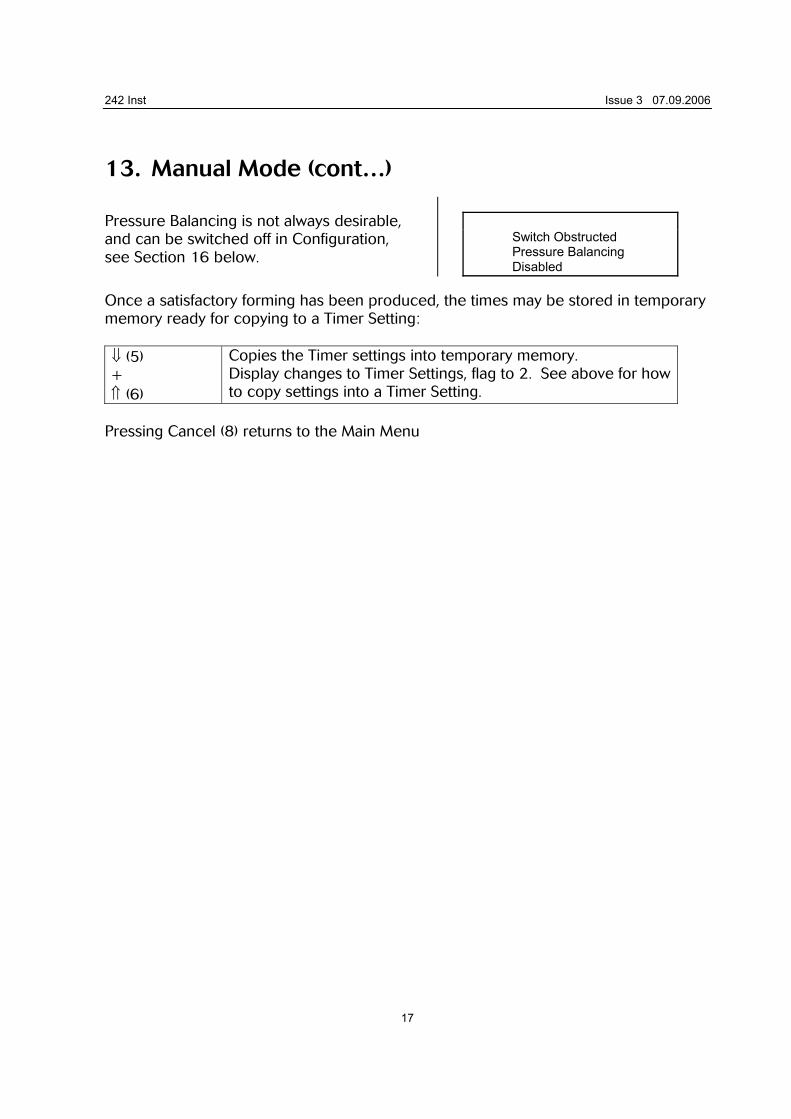
13. Manual Mode (cont…) Pressure Balancing is not always desirable, and can be switched off in Configuration, see Section 16 below.
Switch Obstructed Pressure Balancing Disabled
Once a satisfactory forming has been produced, the times may be stored in temporary memory ready for copying to a Timer Setting: ⇓ (5) + ⇑ (6)
Copies the Timer settings into temporary memory. Display changes to Timer Settings, flag to 2. See above for how to copy settings into a Timer Setting.
Pressing Cancel (8) returns to the Main Menu
242 Inst Issue 3 07.09.2006
18
14. Auto Mode
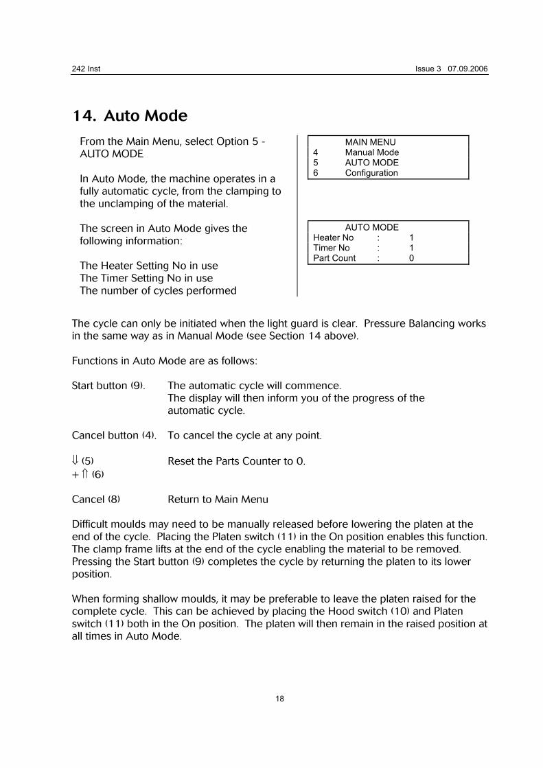
From the Main Menu, select Option 5 - AUTO MODE In Auto Mode, the machine operates in a fully automatic cycle, from the clamping to the unclamping of the material. The screen in Auto Mode gives the following information: The Heater Setting No in use The Timer Setting No in use The number of cycles performed
MAIN MENU 4 Manual Mode 5 AUTO MODE 6 Configuration AUTO MODE Heater No : 1 Timer No : 1 Part Count : 0
The cycle can only be initiated when the light guard is clear. Pressure Balancing works in the same way as in Manual Mode (see Section 14 above). Functions in Auto Mode are as follows: Start button (9). The automatic cycle will commence. The display will then inform you of the progress of the automatic cycle. Cancel button (4). To cancel the cycle at any point. ⇓ (5) Reset the Parts Counter to 0. + ⇑ (6) Cancel (8) Return to Main Menu Difficult moulds may need to be manually released before lowering the platen at the end of the cycle. Placing the Platen switch (11) in the On position enables this function. The clamp frame lifts at the end of the cycle enabling the material to be removed. Pressing the Start button (9) completes the cycle by returning the platen to its lower position. When forming shallow moulds, it may be preferable to leave the platen raised for the complete cycle. This can be achieved by placing the Hood switch (10) and Platen switch (11) both in the On position. The platen will then remain in the raised position at all times in Auto Mode.
242 Inst Issue 3 07.09.2006
19
15. Configuration From the Main Menu, select Option 6 - CONFIGURATION To scroll up and down the Configuration Menu, use buttons ⇓ (5) and ⇑ (6). To return to the Main Menu press Cancel (8). Note that, unlike Timer and Heater Settings, changes to Configuration items are saved as they are made. The Configuration screen gives the following information: Pressure Balancing When switched on, the pressure balancing will operate. When switched off, the pressure balancing will be inactive. Shift + OK Switch On Shift + Cancel Switch Off Max Time This is the maximum time that the Heater system will remain forward in Manual Mode. It is factory set to 200 seconds. Shift + ⇑ Increases Max Time Shift + ⇓ Decreases Max Time PowerSave The 242 software includes a facility to reduce the Heater Power by 50% when it is left idle for a period of time. This can be adjusted from 5 minutes to 30 minutes. Shift + ⇑ Increases PowerSave Timer. Shift + ⇓ Decreases PowerSave Timer. The PowerSave timer can be cancelled and reset either by bringing the Heater Hood forward, or by pressing the Cycle Cancel Button (4). When PowerSave is in operation, the display flashes a Warning message every 10 seconds. Drape Timing In normal operation (drape timing Off), the heating timer will start once the heater hood reaches its forward sensor. With Drape Timing switched On, the timer will not activate until the pressure balancing sensor has been broken for the first time. This can
242 Inst Issue 3 07.09.2006
20
improve accuracy when running the machine over a period of time, as it partially compensates for fluctuations in ambient and machine temperature. When using Drape Timing, it should be noted that the actual heating time recorded in Timer Settings will be lower, as only the point from the sensor being broken to the end of the cycle is timed. It is therefore important to distinguish between settings made with Drape Timing and those without.
Shift + OK Switch On Shift + Cancel Switch Off Hood Ops Plat Ops These show the total number of hood and platen operations that have been performed by the machine. Version No This displays the software version that the machine is running.
242 Inst Issue 3 07.09.2006
21
16. Reducing Plates The 242 Vacuum Forming Machine can be adapted to suit different sizes of sheet material. Reducing Plates (Part No 242R) are available for this purpose. To fit a Reducing Plate, proceed as follows:
1. Isolate the machine from the electrical and compressed air supplies. 2. Unbolt the existing top plate. 3. Remove the large platen mesh from the platen 4. Lay the Reducing Tray into the Platen. 5. Bolt the new top plate onto the machine 6. Remove the two shoulder bolts which attach the rear of the clamp frame to its
pivot points 7. Remove the two clips which secure the front of the clamp frame to the raising
cylinders 8. Remove the clamp frame and fit the new size 9. Refit the shoulder bolts and securing clips
242 Inst Issue 3 07.09.2006
22
17. Maintenance Your 242 Vacuum Forming Machine requires very little in the way of routine maintenance. The following checks should be made, to ensure that the machine continues to run correctly.
Service the vacuum pump in accordance with the Maintenance Schedule (see Appendix 1) Should any circuits not function, check the circuit breakers located in the main switchgear enclosure (inside rear recess adjacent to mains isolator switch).
If there are any queries regarding specifications operation or maintenance of this machine, please contact the manufacturers or their appointed agent.

242 Inst Issue 3 07.09.2006
23
18. Appendix 1