Embed Size (px)
Citation preview
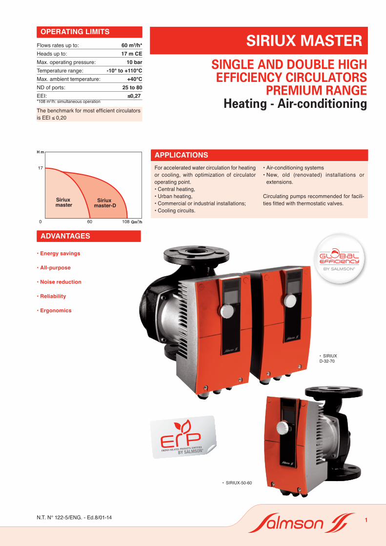
17
0 Qm3/h60 108
H m
Siriux master
Siriux master-D
®
SIRIUX MASTER
For accelerated water circulation for heating or cooling, with optimization of circulator operating point.• Central heating,• Urban heating,• Commercial or industrial installations;• Cooling circuits.
• Air-conditioning systems• New, old (renovated) installations or
extensions.
Circulating pumps recommended for facili-ties fitted with thermostatic valves.
APPLICATIONS
Flows rates up to: 60 m3/h*Heads up to: 17 m CEMax. operating pressure: 10 barTemperature range: -10° to +110°CMax. ambient temperature: +40°CND of ports: 25 to 80EEI: ≤0,27*108 m3/h: simultaneous operation
The benchmark for most efficient circulators is EEI ≤ 0,20
OPERATING LIMITS
SINGLE AND DOUBLE HIGH EFFICIENCY CIRCULATORS
PREMIUM RANGEHeating - Air-conditioning
• SIRIUX-50-60
• SIRIUX D-32-70
ADVANTAGES
• Energy savings
• All-purpose
• Noise reduction
• Reliability
• Ergonomics
N.T. N° 122-5/ENG. - Ed.8/01-14 1

SIRIUX MASTER
• Hydraulic partSingle or double body with threaded or flan-ged. 3D impellers and spiral for maximum optimization of the hydraulic performances.An impeller seal between the pump body and the impeller improves performances further by limiting the internal recycling of the fluid. The pump body is fully cataphoresis coated to ensure corrosion resistance.
• Motor230 V – 50 Hz single-phaseWet rotor motor; bearing bushes lubricated by the fluid pumped.E.C.M. (Electronically Commutated Motor) synchronous motor, equipped with a perma-nent magnet rotor.The stator’s rotating magnetic field is genera-ted by the electronic switching of the coils.This rotating field creates a continuous tor-que through attraction between the rotor’s opposite magnetic poles, controlling its po-sition (synchronous motor). This ensures the optimum performance of the motor, whatever its speed.The wet rotor and the windings are separa-ted by a composite, and therefore completely amagnetic, sleeve, to reduce motor losses.
Speed: 900 to 4800 rpmMains voltage: 1-ph. 230 V ± 10 %Frequency: 50 Hz - 60 HzInsulation class: F (155° C)Protection index: IPX4DEMC compliance: EN 61800-3 emission EN 61000-6-3 immunity EN 61000-6-2
•Protection differential (FI)«All current» FI protection differentials com-pliant with EN 61008-1 are permitted. These differential circuit breakers are identified by
or .
ADVANTAGESDESIGN• Energy savingsHigh efficiency circulators, with optimization of the operating point. Energy savings of up to 80% compared to a traditional circulator.
• All-purposeThese circulators are compatible with all types of heating, air-conditioning and re-frigeration systems. The standard version covers a fluid temperature range from –10°C to +110°C.
• Noise controlEliminating of whistling and hydraulic noises in the thermostatic valves. Automatic adap-ting of speeds to the system’s needs.
• Reliability- Fully automatic operation requiring neither
venting nor servicing. A double filter system prevents solid particles from getting into the rotor chamber. A rotating seal between the impeller and the endshield limits water exchanges with the motor to the bare minimum.
- Circulators shut down via the on/off control start up for a few moments once a day to prevent blocking due to a long period of inactivity.
- The electronic modules have a non-volatile memory for data storage. The setpoints are protected in the case of a power cut.
- Single or double circulators equipped with IF modules (optional, one IF module per motor) allow many control or remote moni-toring functions.
• ErgonomicsEasy electrical connections and adjustments facilitated by direct access via the control mo-dule’s front panel. The position of the display on the LCD screen may be adjusted accor-ding to the position of the control module.Pressure gauge tappings on the flanges.
STANDARD CONSTRUCTIONMain parts MaterialPump casing EN GJL 250
EN GJL 200 for ND 25-30Impeller Glass fibre reinforced PPS
PP for ND 65-80Shaft Chromium steel (X46 – Cr13)Bearing bushes Metal impregnated carbon
Filter3-D Impeller
Spiral seal
3-D body
Condensate Evacuation
IDENTIFICATIONSIRIUX 32 - 70
SIRIUX - D High efficiencycirculator
Single pump or D : double pump
Nominal diameter (ND)of suct/dis. flanges
Head (in dm)at nominal flow
Siriux with EC motor
SXE with AC motor
2

/MODBUS/BACNETMODBUS/BACNET
/
SIRIUX MASTER
POSSIBLE ASSEMBLYCONNECTIONS
On vertical or horizontal pipes the motor shaft must always be horizontal.
Options: IF Modules
• In terminal boxes
L – N: mains connection, 230 V – 50 Hz/60 Hz single-phase current
PE: earth
SSM: dry contact for fault indicator (nor-mal closed, open by default). Max load: 1 A – 250 V – AC
• On IF modules (optional)
DP: double pump (or 2 single pump) management
0-10 V: analog input for external control signal
Ext. Off: remote on/off (through external contact)
SBM: dry contact for operating state indicator (contact normally open; closed if pump runs)
Ext. Min: remote min. operating curve (through external contact)
LON : Serial digital LON interface for connection to LONWORKS networks.
CAN : Serial digital interface for connection to CAN open networks
MODBUS : Serial digital interface for connection to Modbus open networks
BACnet : Serial digital interface for connection to BACnet open networks
OR
OR
OR
OR
OR
OR
3

Modules DP Ext. Off SBM Ext. Min LON Ext. Off / SBM CAN Modbus BACnet
FonctionsGestion pompe double • • • • • • • • •Entrée analogique 0-10 V • • •Marche/Arrêt à distance • •Report de marche • •Marche mini à distance •Interface série LONWORKS •Interface série CAN •Interface série Modbus •Interface série BACnet •
SIRIUX MASTER
The heating or air-conditioning needs of a building vary according to whether it is day or night, but also during the day according to changes in the outside temperature, etc., and even from one point of the building to another as the thermostatic valves or 2-way valves are closed. The self-regulated circulator automatically adjusts its rotation speed according to the mains network’s friction losses, in order to maintain a minimum electricity consumption (ECM technology) and a low operating noise level. The circulator’s properties are adjusted automatically according to the heating or cooling needs of the system.
• Manual adjustmentParameterization of basic functions, i.e.:- ON/OFF;- control mode ∆P constant ∆P variable- and speed adjustment;
• Constant pressure With this regulation mode, electronic control maintains the constant differential pressure of the circulating pump whatever the flow rate, depending on the predefined pressure value.
• Variable pressure With this regulation mode, the electronic control allows reducing the differential pressure (manometric head) in case of flow reduction, depending on the predefined dif-ferential pressure value.
• Speed adjustmentThe speed may be adjusted manually to a constant figure between 900 and 4800 rpm (according to models).
• Automatic idling The considerable development of day/night adjustment installations has produced hourly or thermostatic regulated boilers, but not by the adjustment of circulating pumps, which consume energy accelerating cold water circulation.
• Remote monitoringIn addition, a dry contact (open by default) al-lows the remote monitoring of any operating incident (e.g. through a building management system).
• External control (with IF module)This control mode deactivates controlling by the control module.It provides the following functions by means of a 0-10 V analog signal:- remote adjusting of the setpoint ∆P
– constant- remote adjusting of the setpoint ∆P
– variable- remote adjusting of the speed between the
min speed and the max speed- external on-off.
• LON communication
• CAN communication
• Modbus communication
• BACnet communication
• Double circulatorsEquipped with two IF (InterFace) units, the Siriux benefits from the following extra functions:
Duty/Stand-by The flow requested is provided by a single pump, the other pump starting up in case of fault on first pump or after 24 hours of actual operation of the latter.
Cascade operation At minimum load, only the pump in service operates. The backup pump triggers when radiators request a higher flow rate. From this point (switchover point), the nominal speed of the two pumps increases synchronously in case of need. After 24 hours of actual opera-tion, there is built-in (automatic) changeover of the master pump which becomes slave. This function increases energy saving as compared to usual operation in parallel by avoiding numerous locking/ triggering.(See working curves in cascade opposite).
• Additional functions (IF modules)There are nine types of IF module:- IF module – Ext. Off- IF module – SBM- IF module – Ext. Off / SBM- IF module – Ext. Min.- IF module – DP.- IF module – LON.- IF module – CAN.- IF module – Modbus.- IF module – BACnet.
having the following functions (see table below):
OPERATING PRINCIPLE
FunctionsDouble pump management0-10 V analog inputRemote on/offOperation indicatorRemote min. operationLONWORKS Serial InterfaceCAN Serial InterfaceModbus Serial InterfaceBACnet Serial Interface
4

H min
H n
H
Q
Mode ∆P constant
Zone de fonctionnementnon utilisée
Fonctionnement en ∆P constant
H min
H n
1/2 H n
H
Q
Mode ∆P variable
Economie supplémentaireréalisée par rapportau mode ∆P constant
Fonctionnement en ∆P variable
)
%( eébrosba ecnassiuP
Puissance absorbée
C( trapéd erutarép
meT°)
Température départ/heures
12h 18h 0h 6h 12h 18h 0h 6h 12h 18h0
20
40
60
80
100
120
0
10
20
30
40
50
60
Fonctionnement en ralenti automatique
n [1/min]
n max
n min
AusU [V]1 32 10
H max
H min
Aus
H [m]
U [V]1 32 10
n [1/min]
n max
n min
AusU [V]1 32 10
H max
H min
Aus
H [m]
U [V]1 32 10
0
0,2
0,4
0,6
0,8
1,0
1,2
P1(kW)
Qm3/h 5 10 15 20 25 30 35 40
Cascade classiqueMarche parallèleCascade avec optimisationdes performances
Point de commutation
Fonctionnement en cascade synchronisée
0
0,2
0,4
0,6
0,8
1,0
1,2
P1 (kW)
Qm 3 /h 5 10 15 20 25 30 35 40
Cascade classique Marche parallèle Cascade avec optimisation des performances
Point de commutation
Fonctionnement en cascade synchronisée
SIRIUX MASTER
OPERATING PRINCIPLE
Electronic module maintains constant the dif-ferential pressure produced by the pump at the differential pressure value of Hn instruc-tion, up to the curve of operating data through the authorized flow rating.
Electronic module modifies linearly the diffe-rential pressure value between Hn and 1/2 Hn instruction to be met by the pump. Differential pressure value of H instruction increases or decreases acc. to the requested flow rate.
This device enables making up to 25% ad-ditional saving as compared to operation in ∆P constant.When the heating facility reaches a certain low temperature, the circulator runs on a constant reduced speed until a new rise in temperature.
Operation in cascade of a SIRIUX fitted with two IF modules.At equivalent flow rate, the circulator automatically uses the curve of least power.
CONTROLS
Remote controlling of the speed by a 0-10 V signal
Remote controlling of the differential head by a 0-10 V signal
∆P Constant Mode ∆P Variable Mode Auto operating mode (setback func-tion)
Efficiency-optimized peak-load operation
Operation area not used
Additional sa-vings compared with constant ∆P mode
Power input
Pow
er in
put (
%)
Star
ting
tem
pera
ture
(C°)
Température start/hours
Usual cascade
Parallel operation
Cascade with performance optimization
Switchover point
5

SIRIUX MASTER
TABLE OF FUNCTIONS
Siriux Siriux D
Operating modes
Speed-stage switching — —
Remote speed control (n = constant) • •
∆p-c for constant differential pressure • •
∆p-v for variable differential pressure • •
Manual functions
Adjustment of operating mode • •
Adjustment of differential-pressure setpoint • •
Adjustment of «autopilot» (automatic setback mode) • •
Selection Pump ON/OFF • •
Adjustment of speed (manual setting mode) • •
Adjustment of speed stages — —
Automatic functions
Smooth adjustment of power depending on the operating mode • •
«Autopilot» automatic setback mode • •
Deblocking function • •
Soft start • •
Full motor protection with integrated trip electronics • •
External control functions 1)
Control input «Overriding Off» Possible with Siriux interfacemodules (accessory)
Possible with Siriux interface modules (accessory)
Control input «Overriding Min» Possible with Siriux interface modules (accessory)
Possible with Siriux interface modules (accessory)
Control input „Analog In 0 ... 10 V“ (remote speed setting) Possible with Siriux interface modules (accessory)
Possible with Siriux interface modules (accessory)
Control input „Analog In 0 ... 10 V“ (remote setpoint setting) Possible with Siriux interface modules (accessory)
Possible with Siriux interface modules (accessory)
Signal and display functions
Collective fault signal (potential free NC contact) • •
Individual run signal (potential free NO contact) Possible with Siriux interface modules (accessory)
Possible with Siriux interface modules (accessory)
Fault light • •
LC display for showing pump data and fault codes • •
6

SIRIUX MASTER
TABLE OF FUNCTIONS
Siriux Siriux D
Data exchange
Infrared interface for wireless data exchange with Salmson Pump Control (see Salmson Pump Control function table)
• •
Serial digital LON interface for connection to a LONWORKS network
Possible with Siriux interface modules (accessory)
Possible with Siriux interface modules (accessory)
Serial digital interface for connection to a CAN open, Modbus, BACnet networks
Possible with Siriux interface modules (accessory)
Possible with Siriux interface modules (accessory)
Dual pump management (double pumps or 2 x single pump) 2)
Main/standby pump operation (automatic faultactuated duty changeover/time-sensitive pump alteration)
Possible with Siriux interfacemodules (accessory)
Various combinations with Siriux interface modules (accessory) possible
Cascade mode (switched on and off for peak loads to optimise efficiency) Possible with Siriux interfacemodules (accessory)
Various combinations with Siriux interface modules (accessory) possible
Equipment / scope of delivery
Wrench attachment point on pump body Threaded types with P2 < 140 W —
Double changeover valve in pump housing — •
Cable entry possible on both sides — —
Integrated air separator for automatic rapid ventilation Rp 3/8 — —
Plug-in slot for optional extension with SALMSON IF modules • •
Blocking-current-proof motor — —
Included seals for threaded connection or flanges (loose) • —
Included installation and operating instructions • •
Included heat insulation — —
Included bolts and washers for flanges (for DN 32 - DN 80 nominal connection diameters) • •
Particle filter • •
• = available ; — = not available1) Choose the appropriate IF module2) With 2 IF modules
7

SIRIUX MASTER
TECHNICAL DATA - SIRIUX25
-30
25-4
0
25-6
0
25-6
5
32-3
0
32-4
0
32-6
0
32-6
5
32-6
5F
32-9
0
32-7
0
40-3
0
40-6
0
40-6
5
40-8
0
40-1
10
50-6
0
50-6
5
50-7
0
50-8
0
50-1
10
65-8
0
65-9
0
65-1
10
80-9
0
Approved fluids(other fluids on request)
Heating water (as per VDI 2035) •
Water/glycol-mixtures (max. 1:1; mixtures with more than 20 % glycol content require rechecking of the pumping data)
•
Drinking water and water for food businesses in accordance with TrinkwV 2001
—
Performance
Max. delivery head [m] 4 6 7 10 4 8 7 10 10 11 9 5 8 10 12 17 8 10 9 11 17 10 11 16 13
Flow rate max. [m3/h] 4 7 8 9 4 7 8 9 9 10 13 11 13 9 21 23 13 9 24 29 43 29 41 52 61
Permitted field of application
Temperature range when used in heating, ventilation & air conditioning systems- at max. ambient temperature +40 °C [°C]
-10 to +110
Temperature range for usein drinking-water circulation systems
- at max. ambient temperature +40 °C [°C] —
- at max. ambient temperature +40 °C in short-term operation 2 h [°C]
—
Max. permissible total hardness in drinking watercirculation systems [°d]
—
Standard version with nominal pressure,p max [bar]
6/10 10
Special version with nominal pressure,p max [bar]
16 16
Pipe connections
Pipe connection 1 1 1 1 11/4 11/4 11/4 11/4 11/4
Nominal diameter 32 32 40 40 40 40 40 50 50 50 50 50 65 65 65 80
Flange for mating flange PN 10, standard version — — — — — — — — — — — — — — — — — — — — — — — — •
Flange for mating flange PN 16, special version — — — — — — — — • — • • • • • • • • • • • • • • •
Combination flange PN 6/10 for mating flanges PN 6 and PN 16, standard version
— — — — — — — — • — • • • • • • • • • • • • • • —
Support-bracket mounting (with horizontal shaft only), standard version
— — — — — — — — — — — — — — — — — — — — — — — — —
Support-bracket mounting (with horizontal shaft only), special version
— — — — — — — — — — — — — — — — — — — — — — — — —
8

SIRIUX MASTER
TECHNICAL DATA - SIRIUX25
-30
25-4
0
25-6
0
25-6
5
32-3
0
32-4
0
32-6
0
32-6
5
32-6
5F
32-9
0
32-7
0
40-3
0
40-6
0
40-6
5
40-8
0
40-1
10
50-6
0
50-6
5
50-7
0
50-8
0
50-1
10
65-8
0
65-9
0
65-1
10
80-9
0
Electrical connection
Mains supply connection 1~[V], standard version 230
Mains suppply connection 3 ~[V], standard version 230
Mains supply connection 3 ~[V], with optional switching plug
—
Mains frequency [Hz] 50/60
Motor/electronics
Electromagnetic compatibility EN 61800-3
Emitted interference EN 61000-6-3
Immunity to interference EN 61000-6-2
Power electronics Frequency converter
Protection class IPX4D
Insulation class F
• = available ; — = not available
9

SIRIUX MASTER
TECHNICAL DATA - SIRIUX D
32-60 32-70 40-60 40-80 40-110 50-60 50-70 50-80 50-110 65-90 65-110 80-90
Approved fluids(other fluids on request)
Heating water (as per VDI 2035) •
Water/glycol-mixtures (max. 1:1; mixtures with more than 20 % glycol content require rechecking of the pumping data) •
Drinking water and water for food businesses in accordance with TrinkwV 2001 —
Performance
Max. delivery head [m] 7 9 8 12 17 8 9 11 17 11 17 13
Flow rate max. [m3/h] 13 19 21 32 35 21 38 43 58 72 80 107
Permitted field of application
Temperature range when used in heating, ventilation & air conditioning systems- at max. ambient temperature +40 °C [°C]
-10 to +110
Temperature range for usein drinking-water circulation systems
- at max. ambient temperature +40 °C [°C] —
- at max. ambient temperature +40 °Cin short-term operation 2 h [°C] —
Max. permissible total hardnessin drinking watercirculation systems [°d] —
Standard version with nominal pressure, p max [bar] 6/10 10
Special version with nominal pressure, p max [bar] 16 16
Pipe connections
Pipe connection
Nominal diameter 32 32 40 40 40 50 50 50 50 65 65 80
Flange for mating flange PN 6, standard version — — — — — — — — — — — •
Flange for mating flange PN 16, special version • • • • • • • • • • • •
Combination flange PN 6/10 for mating flanges PN 6 and PN 16, standard version • • • • • • • • • • • —
Electrical connection
Mains supply connection 1~ [V], standard version 230
Mains suppply connection 3 ~ [V], standard version 230
Mains supply connection 3 ~ [V], with optional switching plug —
Mains frequency [Hz] 50/60
Motor/electronics
Electromagnetic compatibility EN 61800-3
Emitted interference EN 61000-6-3
Immunity to interference EN 61000-6-2
Power electronics Frequency converter
Protection class IPX4D
Insulation class F• = available ; — = not available
10

Δp-c
0 1 2 3 4
0 0,2 0,4 0,6 0,8 1,0 1,2
0 4 8 12
0 0,5 1 1,5 2 2,5
0
1
2
3
4
0
10
20
16
30
40
0 1 2 3 40
20
40
Qm³/h
Ql/s
m/s
Q Igpm
p/kPa
Qm³/h
Hm
P1 W
Δp-vP1 W
Rp 1
Rp 1¼
max.
min.
4m 3,5m 2,5m 2m 1,5m 1m3m
max.
0 0,4 0,8 1,2 1,6
min.
0 1 2 3 40
20
40
Qm³/h
SIRIUX 25-30SIRIUX 32-301~230 V - Rp 1, Rp 1¼
3,5m 2,5m3mmin.
max.
4m 2m
0 1 2 3 4 5 6 7
0 0,4 0,8 1,2 1,6 2,0
0 5 10 15 20 25
0
1
2
3
4
5
6
7
0
10
20
30
40
50
60
70
0 1 2 3 4 5 6 70
40
80
0 1 2 3 4 5 6 70
40
80
0 1 2 3 4
0 0,5 1 1,5 2 2,5m/s
p/kPa
Δp-c
Hm
P1 W
Δp-vP1 W
Rp 1
Rp 1¼
max.
Qm³/h
Ql/s
Q Igpm
Qm³/h
Qm³/h
SIRIUX 25-40SIRIUX 32-401~230 V - Rp 1 / Rp 1¼
max.
max.
min.
2m3m6m 5m 4m1m
max.
2m3m4m5m6m
min.
min.
0 1 2 3 4
0 0,2 0,4 0,6 0,8 1,0 1,2
0 4 8 12
0
1
2
3
4
0
10
20
30
40
0 1 2 3 40
20
40
16
p/kPa
Ql/s
Q Igpm
Qm³/h
Hm
P1 W
0 0,5 1 1,5 2 2,5m/s
Rp 1
Rp 1¼0 0,4 0,8 1,2 1,6
Qm³/h
SIRIUX 25-30SIRIUX 32-301~230 V - Rp 1, Rp 1¼
2400 1/min - 8 V
2200 1/min - 7 V
2000 1/min - 6 V
1800 1/min - 5 V1600 1/min - 4 V1400 1/min - 3 V
9 V8 V7 V5 V4 V3 V
26001/min-9 V
28001/min-10 V
6 V
n=const
0 1 2 3 4 5 6 7
0 0,4 0,8 1,2 1,6 2,0
0 5 10 15 20 25
0 1 2 3 4 5 6 70
40
80
0
1
2
3
4
5
6
7
0
10
20
30
40
50
60
70
p/kPa
Qm³/h
Ql/s
Q Igpm
Qm³/h
0 1 2 3 4
0 0,5 1 1,5 2 2,5m/s
Rp 1
Rp 1¼Hm
P1 W
9 V10 V 8 V 7 V5 V 4 V
3 V
6 V
SIRIUX 25-40SIRIUX 32-401~230 V - Rp 1 / Rp 1¼
2540 1/min - 7 V
2260 1/min - 6 V1970 1/min - 5 V1690 1/min - 4 V1400 1/min - 3 V
3400 1/min - 10 V
3110 1/min - 9 V
2830 1/min - 8 V
n=const
SIRIUX MASTER
SIRIUX 25-30 32-30 AND SIRIUX 25-40 32-40 HYDRAULIC PERFORMANCES
11

max.
min.
max.
min.
0 2 4 6 8
0 0,5 1 1,5 2 2,5
0 5 10 15 20 25 30
0 1 2 3 4 5
0
1
2
3
4
5
6
7
0
10
20
30
40
50
60
70
0 2 4 6 80
50
100
150
0 0,5 1 1,5 2 2,5 3 3,5
Δp-vP1 W
m/sRp 1
Rp 1¼
max.
Qm³/h
p/kPa
Δp-c
Hm
P1 W
Ql/s
Q Igpm
Qm³/h
Qm³/h
SIRIUX 25-60SIRIUX 32-601~230 V - Rp 1 / Rp 1¼
0 2 4 6 80
50
100
150
1m
3m4m5m6m7m 2m
min.
2m3m4m5m6m7m
0 2 4 6 8
0 0,5 1,0 1,5 2,0 2,5
0 5 10 15 20 25 30
0
2
4
6
8
10
0
20
40
60
80
100
0 2 4 6 80
50
100
150200
min.
max.
min.
Δp-vP1 W
max.
p/kPaHm
Δp-cP1 W
0 1 2 3 4 5
0 0,5 1 1,5 2 2,5 3 3,5m/s
Rp 1
Rp 1¼
SIRIUX 25-65SIRIUX 32-651~230 V - Rp 1 / Rp 1¼
Qm³/h
Qm³/h
Ql/s
Q Igpm
Qm³/h
6m7m8m9m10m 5m 4m 3m
2m
1m
min.
max.
0 2 4 6 80
50
100
150
200
6m7m8m9m 5m 4m 3m
2m
0 2 4 6 8
0 0,5 1,0 1,5 2,0 2,5
0 5 10 15 20 25 30
0
1
2
3
4
5
6
7
0
10
20
30
40
50
60
70
0 2 4 6 80
50
100
150
p/kPa
Qm³/h
Ql/s
Q Igpm
Qm³/h
0 1 2 3 4 5
0 0,5 1 1,5 2 2,5 3 3,5m/s
Rp 1
Rp 1¼
SIRIUX 25-60SIRIUX 32-601~230 V - Rp 1 / Rp 1¼
9 V10 V 8 V7 V
5 V4 V3 V
6 V
2710 1/min - 7 V
2390 1/min - 6 V
2060 1/min - 5 V
1730 1/min - 4 V1400 1/min - 3 V
3700 1/min - 10 V
3370 1/min - 9 V
3040 1/min - 8 V
Hm
P1 Wn=const
0 2 4 6 8
0 0,5 1,0 1,5 2,0 2,5
0 5 10 15 20 25 30
0
2
4
6
8
10
0
20
40
60
80
100
0 2 4 6 80
50
100
150
Ql/s
Q Igpm
Qm³/h
0 1 2 3 4 5
0 0,5 1 1,5 2 2,5 3 3,5m/s
Rp 1
Rp 1¼
SIRIUX 25-65SIRIUX 32-651~230 V - Rp 1 / Rp 1¼
3140 1/min - 7 V
2710 1/min - 6 V
2270 1/min - 5 V1840 1/min - 4 V1400 1/min - 3 V
4450 1/min - 10 V
4010 1/min - 9 V
3580 1/min - 8 V
p/kPaHm
Qm³/h
P1 Wn=const
3 V 4 V5 V
6 V7 V
8 V9 V10 V
SIRIUX MASTER
SIRIUX 25-60 32-60 AND SIRIUX 25-65 32-65 HYDRAULIC PERFORMANCES
12

0 2 4 6 8 100
50
100
150
0 2 4 6 8 10
0 0,5 1,0 1,5 2,0 2,5 3,0
0 10 20 30
0 1 2 3
0
2
4
6
8
10
0
20
40
60
80
100
0 2 4 6 8 100
50
100
150200
min.
max.
p/kPaHm
Δp-cP1 W
m/s
Qm³/h
Qm³/h
Ql/s
Q Igpm
Qm³/h
6m7m8m9m10m 5m 4m 3m
2m
1m
Δp-vP1 W
200
6m7m8m9m 5m 4m 3m
2m
max.
4
SIRIUX 32-65 F1~230 V - DN 32
min.
min.
max.
10m
0 2 4 6 8 10 12
0 1 2 3 4
0 10 20 30 40 50
0 1 2 3 4 5
14
14
0
2
4
6
8
0
20
40
60
80
0 2 4 6 8 10 120
100
200
300
max.
p/kPaHm
Δp-cP1 W
m/s
Qm³/h
14 Qm³/h
Ql/s
Q Igpm
Qm³/h
6m7m8m9m 5m 4m
3m
2m
SIRIUX 32-701~230 V - DN 32
max.
max.
1m min.
Δp-vP1 W
0
100
200
300
min.
0 2 4 6 8 10 12
6m7m8m 5m 4m
min.
0 2 4 6 8 10
0 0,5 1,0 1,5 2,0 2,5 3,0
0 10 20 30
0 1 2 3
0
2
4
6
8
10
0
20
40
60
80
4
100
0 2 4 6 8 100
50
100
150
m/s
SIRIUX 32-65 F1~230 V - DN 32
Ql/s
Q Igpm
Qm³/h
3140 1/min - 7 V
2710 1/min - 6 V
2270 1/min - 5 V
1840 1/min - 4 V1400 1/min - 3 V
4450 1/min - 10 V
4010 1/min - 9 V
3580 1/min - 8 V
p/kPaHm
Qm³/h
P1 Wn=const
3 V5 V
6 V
7 V8 V9 V10 V
4 V
0 2 4 6 8 10 12
0 1 2 3 4
500 10 20 30 40
0 1 2 3 4 5
0
2
4
6
8
0
20
14
14
40
60
80
0 2 4 6 8 10 120
100
200
300
m/s
SIRIUX 32-701~230 V - DN 32
Ql/s
Q Igpm
Qm³/h
3140 1/min - 7 V
2710 1/min - 6 V
2270 1/min - 5 V
1840 1/min - 4 V1400 1/min - 3 V
4450 1/min - 10 V
4010 1/min - 9 V
3580 1/min - 8 V
p/kPaHm
Qm³/h
P1 Wn=const
3 V5 V
6 V7 V
8 V9 V10 V
4 V
SIRIUX MASTER
SIRIUX 32-65F AND SIRIUX 32-70 HYDRAULIC PERFORMANCES
13

0 2 4 6 8 10
0 0,5 1,0 1,5 2,0 2,5 3,0
0 10 20 30
0 1 2 3 4
0
2
4
6
8
10
12
0
20
40
60
80
100
120
0 2 4 6 8 100
100
200
300
max.
p/kPaHm
Δp-cP1 W
Δp-vP1 W
m/s
Qm³/h
Qm³/h
Ql/s
Q Igpm
Qm³/h
6m7m8m9m10m11m 5m 4m
3m
2m
SIRIUX 32-901~230 V - Rp 1¼
max.
max.
min.
1m min.
0 2 4 6 8 100
100
200
3006m7m8m9m10m 5m 4m
min.
Δp-vP1 W
0 2 4 6 8 10 12
0 0,5 1,0 1,5 2,0 2,5 3,0 3,5
0 10 20 30 40
0 0,5 1,0 1,5 2,0 2,5
0
1
2
3
4
5
0
10
20
30
40
50
0 2 4 6 8 10 120
40
80
Ql/s
Q Igpm
Qm³/h
Qm³/h
Qm³/h
Wilo-Stratos 40/1-41~230 V - DN 40
max.
p/kPaHm
Δp-cP1 W
m/s
1,5m2m2,5m3m3,5m4m4,5m5m
1m
SIRIUX 40-301~230 V - DN 40
max.
min.
min.
min.
0 2 4 6 8 10 120
40
80
120
1202,5m
3m3,5m4m4,5m
5m 2m
max.
m/s
SIRIUX 32-901~230 V - Rp 1¼
Ql/s
Q Igpm
Qm³/h
p/kPaHm
Qm³/h
P1 Wn=const
0 2 4 6 8 10
0 0,5 1,0 1,5 2,0 2,5 3,0
0 10 20 30
0 1 2 3 4
0
2
4
6
8
10
12
0
20
40
60
80
100
120
0 2 4 6 8 100
100
200
3340 1/min - 7 V
2860 1/min - 6 V
2370 1/min - 5 V
1890 1/min - 4 V1400 1/min - 3 V
4800 1/min - 10 V
4310 1/min - 9 V
3830 1/min - 8 V
5 V6 V
7 V8 V
9 V10 V
4 V3 V
0 2 4 6 8 10 12
0 0,5 1,0 1,5 2,0 2,5 3,0 3,5
0 10 20 30 40
0 0,5 1,0 1,5 2,0 2,5
0
1
2
3
4
5
0
10
20
30
40
50
0 2 4 6 8 10 120
40
80
3700 1/min - 10 V
2800 1/min - 7 V
2500 1/min - 6 V
2200 1/min - 5 V
1900 1/min - 4 V1600 1/min - 3 V
3400 1/min - 9 V
3100 1/min - 8 V
m/s
SIRIUX 40-301~230 V - DN 40
Ql/s
Q Igpm
Qm³/h
p/kPaHm
Qm³/h
P1 Wn=const
5 V6 V
7 V8 V9 V10 V
4 V3 V
PERFORMANCES HYDRAULIQUES DES SIRIUX 25-60 32-60 ET SIRIUX 25-65 32-65
SIRIUX MASTER
SIRIUX 32-90 AND SIRIUX 40-30 HYDRAULIC PERFORMANCES
14

0 4 8 12 16
16
0 1 2 3 4 5
0 10 20 30 40 50
0
2
4
6
8
0
20
40
60
80
0 4 8 12
60
0
100
200
300
SIRIUX 40-601~230 V - DN 40
0 1 2 3 4m/s
Qm³/h
Δp-vP1 W
max.
p/kPaHm
Δp-cP1 W
Qm³/h
Ql/s
Q Igpm
Qm³/h
5m6m7m8m 4m 3m
2m
max.
1m min.
min.
0 4 8 12 160
100
200
300max.
min.
5m6m7m 4m 3m
0 2 4 6 8 100
50
100
150
0 2 4 6 8 10
0 0,5 1,0 1,5 2,0 2,5 3,0
0 10 20 30
0
2
4
6
8
10
0
20
40
60
80
100
0 2 4 6 8 100
50
100
150200
min.
max.
p/kPaHm
Δp-cP1 W
Qm³/h
Qm³/h
Ql/s
Q Igpm
Qm³/h
6m7m8m9m10m 5m 4m 3m
2m
1m
Δp-vP1 W
200
6m7m8m9m 5m 4m 3m
2m
max.
min.
min.
max.
10m
m/s0 0,4 0,8 1,2 1,6 2,0 2,4
SIRIUX 40-651~230 V - DN 40
0 4 8 12 16
0 1 2 3 4 5
0 10 20 30 40 50
0 1 2 3
0
2
4
6
8
0
20
40
60
80
0 4 8 12 16
60
0
100
200
4
SIRIUX 40-601~230 V - DN 40
p/kPa
Qm³/h
Ql/s
Q Igpm
Qm³/h
m/s
Hm
P1 W
9 V10 V8 V
7 V
5 V4 V3 V
6 V
3340 1/min - 7 V
2860 1/min - 6 V
2370 1/min - 5 V1890 1/min - 4 V1400 1/min - 3 V
4800 1/min - 10 V
4310 1/min - 9 V
3830 1/min - 8 V
n=const
0 2 4 6 8 10
0 0,5 1,0 1,5 2,0 2,5 3,0
0 10 20 30
0
2
4
6
8
10
0
20
40
60
80
100
0 2 4 6 8 100
50
100
150
m/s
Ql/s
Q Igpm
Qm³/h
3140 1/min - 7 V
2710 1/min - 6 V
2270 1/min - 5 V
1840 1/min - 4 V1400 1/min - 3 V
4450 1/min - 10 V
4010 1/min - 9 V
3580 1/min - 8 V
p/kPaHm
Qm³/h
P1 Wn=const
3 V5 V
6 V
7 V8 V9 V10 V
4 V
0 0,4 0,8 1,2 1,6 2,0 2,4
SIRIUX 40-651~230 V - DN 40
SIRIUX MASTER
SIRIUX 40-60 AND SIRIUX 40-65 HYDRAULIC PERFORMANCES
15

0 4 8 12 16 20
0 1 2 3 4 5 6
0 20 40 60
0 1 2 3 4
0
2
4
6
8
10
12
0
20
40
60
80
100
120
5
0 4 8 12 16 200
200
400
max.
p/kPaHm
Δp-cP1 W
m/s
Qm³/h
Qm³/h
Ql/s
Q Igpm
Qm³/h
6m7m8m9m10m11m12m 5m 4m
3m
2m
SIRIUX 40-801~230 V - DN 40
max.
max.
1mmin.
min.
min.
Δp-vP1 W
0 4 8 12 16 200
200
4006m7m8m9m10m
11m12m
5m 4m
0 5 10 15 20 25
0 2 4 6
0 20 40 60 80
0 1 2 3 4 5
0
4
8
12
16
0
40
80
120
160
0 5 10 15 20 250
200
400
m/s
SIRIUX 40-1101~230 V - DN 40
SIRIUX 40-1101~230 V - DN 40
Ql/s
QIgpm
Qm³/h
p kPaHm
Qm³/h
P1 Wn=const
6
0 1 2 3 4 5 m/s6
2410 1/min - 7 V
2040 1/min - 6 V
1680 1/min - 5 V
950 1/min - 3 V
3500 1/min - 10 V
3140 1/min - 9 V
2770 1/min - 8 V
max.
Δp-vP1 W
Qm³/h
p kPaHm
Δp-cP1 W
Qm³/h
Ql/s
QIgpm
Qm³/h
max.
min.
min.
max.
0 5 10 15 20 25
0 2 4 6
0 20 40 60 80
0
4
8
12
16
0
40
80
120
160
0 5 10 15 20 250
200
400
600
1310 1/min - 4 V
10 V
3 V
5 V
6 V
7 V8 V9 V
4 V
min.
16m14m 12m 10m 8m
6m
4m
2m1m
0 5 10 15 20 250
200
400
600 14m
12m 10m 8m 6m
16m
4m
SIRIUX 40-1101~230 V - DN 40
0 5 10 15 20 25
0 2 4 6
0 20 40 60 80
0 1 2 3 4 5
0
4
8
12
16
0
40
80
120
160
0 5 10 15 20 250
200
400
m/s
SIRIUX 40-1101~230 V - DN 40
SIRIUX 40-1101~230 V - DN 40
Ql/s
QIgpm
Qm³/h
p kPaHm
Qm³/h
P1 Wn=const
6
0 1 2 3 4 5 m/s6
2410 1/min - 7 V
2040 1/min - 6 V
1680 1/min - 5 V
950 1/min - 3 V
3500 1/min - 10 V
3140 1/min - 9 V
2770 1/min - 8 V
max.
Δp-vP1 W
Qm³/h
p kPaHm
Δp-cP1 W
Qm³/h
Ql/s
QIgpm
Qm³/h
max.
min.
min.
max.
0 5 10 15 20 25
0 2 4 6
0 20 40 60 80
0
4
8
12
16
0
40
80
120
160
0 5 10 15 20 250
200
400
600
1310 1/min - 4 V
10 V
3 V
5 V
6 V
7 V8 V9 V
4 V
min.
16m14m 12m 10m 8m
6m
4m
2m1m
0 5 10 15 20 250
200
400
600 14m
12m 10m 8m 6m
16m
4m
SIRIUX 40-1101~230 V - DN 40
0 4 8 12 16 20
0 1 2 3 4 5 6
0 20 40 60
0 1 2 3 4
0
2
4
6
8
10
12
0
20
40
60
80
100
120
5
0 4 8 12 16 200
200
400
m/s
SIRIUX 40-801~230 V - DN 40
Ql/s
Q Igpm
Qm³/h
3230 1/min - 7 V
2770 1/min - 6 V
2310 1/min - 5 V
1860 1/min - 4 V1400 1/min - 3 V
4600 1/min - 10 V
4140 1/min - 9 V
3690 1/min - 8 V
p/kPaHm
Qm³/h
P1 Wn=const
3 V5 V
6 V7 V
8 V9 V10 V
4 V
SIRIUX MASTER
SIRIUX 40-80 AND SIRIUX 40-110 HYDRAULIC PERFORMANCES
16

0 4 8 12 16
16
0 1 2 3 4 5
0 10 20 30 40 50
0
2
4
6
8
0
20
40
60
80
0 4 8 12
60
0
100
200
300
SIRIUX 50-601~230 V - DN 50
0 0,5 1,0 1,5 2,0 2,5m/s
Qm³/h
Δp-vP1 W
max.
p/kPaHm
Δp-cP1 W
Qm³/h
Ql/s
Q Igpm
Qm³/h
5m6m7m8m 4m 3m
2m
max.
1m min.
min.
0 4 8 12 160
100
200
300max.
min.
5m6m7m 4m 3m
0 4 8 12 16
0 1 2 3 4 5
0 10 20 30 40 50
0 1 2 3
0
2
4
6
8
0
20
40
60
80
0 4 8 12 16
60
0
100
200
4
p/kPa
Qm³/h
Ql/s
Q Igpm
Qm³/h
m/s
Hm
P1 W
9 V10 V8 V
7 V
5 V4 V3 V
6 V
3340 1/min - 7 V
2860 1/min - 6 V
2370 1/min - 5 V1890 1/min - 4 V1400 1/min - 3 V
4800 1/min - 10 V
4310 1/min - 9 V
3830 1/min - 8 V
n=const
SIRIUX 50-601~230 V - DN 50
0 2 4 6 8 100
50
100
150
0 2 4 6 8 10
0 0,5 1,0 1,5 2,0 2,5 3,0
0 10 20 30
0
2
4
6
8
10
0
20
40
60
80
100
0 2 4 6 8 100
50
100
150200
min.
max.
p/kPaHm
Δp-cP1 W
Qm³/h
Qm³/h
Ql/s
Q Igpm
Qm³/h
6m7m8m9m10m 5m 4m 3m
2m
1m
Δp-vP1 W
200
6m7m8m9m 5m 4m 3m
2m
max.
min.
min.
max.
10m
m/s0 0,4 0,8 1,61,2
SIRIUX 50-651~230 V - DN 50
0 2 4 6 8 10
0 0,5 1,0 1,5 2,0 2,5 3,0
0 10 20 30
0
2
4
6
8
10
0
20
40
60
80
100
0 2 4 6 8 100
50
100
150
m/s
Ql/s
Q Igpm
Qm³/h
3140 1/min - 7 V
2710 1/min - 6 V
2270 1/min - 5 V
1840 1/min - 4 V1400 1/min - 3 V
4450 1/min - 10 V
4010 1/min - 9 V
3580 1/min - 8 V
p/kPaHm
Qm³/h
P1 Wn=const
3 V5 V
6 V
7 V8 V9 V10 V
4 V
0 0,4 0,8 1,2 1,6
SIRIUX 50-651~230 V - DN 50
SIRIUX MASTER
SIRIUX 50-60AND SIRIUX 50-65 HYDRAULIC PERFORMANCES
17

0 5 10 15 20 25
0 2 4 6
max.
p/kPaHm
Δp-cP1 W
m/s
Qm³/h
Ql/s
Q Igpm
Qm³/h
SIRIUX 50-701~230 V - DN 50
min.
0 20 40 60 80
0 1 2 3
0
2
4
6
8
0
20
40
60
80
4
0 5 10 15 20 250
200
4006m7m8m9m 5m 4m 3m
2m
max.
min.1m
0 5 10 15 20 250
100
200
300400
Qm³/h
Δp-vP1 W max.
6m7m8m9m 5m 3m4m
min.
0 5 10 15 20 25
0 2 4 6
0 20 40 60 80
0 1 2 3
0
2
4
6
8
0
20
40
60
80
4
0 5 10 15 20 250
200
400
m/s
SIRIUX 50-701~230 V - DN 50
Ql/s
Q Igpm
Qm³/h
p/kPaHm
Qm³/h
P1 Wn=const
2940 1/min - 7 V
2560 1/min - 6 V
2170 1/min - 5 V
1790 1/min - 4 V1400 1/min - 3 V
4100 1/min - 10 V
3710 1/min - 9 V
3330 1/min - 8 V
5 V6 V
7 V8 V9 V
10 V
4 V3 V
0 5 10 15 20 25 30
0 2 4 6 8
0 20 40 60 80
0 1 2 3 4
0
2
4
6
8
10
12
0
20
40
60
80
100
100
120
0 5 10 15 20 25 300
200
400
600
max.
p/kPaHm
Δp-cP1 W
m/s
Qm³/h
Ql/s
Q Igpm
Qm³/h
6m7m8m9m10m11m 5m 4m
3m
2m
SIRIUX 50-801~230 V - DN 50
max.
1m min.
min.
min.
Qm³/h
Δp-vP1 W
0 5 10 15 20 25 300
200
400
600 max.
11m 6m7m8m9m10m 4m5m
0 5 10 15 20 25
100
30
0 2 4 6 8
0 20 40 60 80
0 1 2 3 4
0
2
4
6
8
10
12
0
20
40
60
80
100
120
0 5 10 15 20 25 300
200
400
m/s
SIRIUX 50-801~230 V - DN 50
Ql/s
Q Igpm
Qm³/h
3230 1/min - 7 V
2770 1/min - 6 V
2310 1/min - 5 V
1860 1/min - 4 V1400 1/min - 3 V
4600 1/min - 10 V
4140 1/min - 9 V
3690 1/min - 8 V
p/kPaHm
Qm³/h
P1 Wn=const
3 V5 V
6 V7 V
8 V9 V10 V
4 V
SIRIUX MASTER
SIRIUX 50-70 AND SIRIUX 50-80 HYDRAULIC PERFORMANCES
18

0 10 20 30 40
0 2 4 6 8 10 12
0 40 80 120 160
0 1 2 3 4 5 6
0
4
8
12
16
0
40
80
120
160
0 10 20 30 400
400
800
Δp-vP1/W
max.
min.
min.
max.
2350 1/min - 7 V
2000 1/min - 6 V
1650 1/min - 5 V
950 1/min - 3 V
3400 1/min - 10 V
3050 1/min - 9 V
2700 1/min - 8 V
1300 1/min - 4 V
10 V
3 V
7 V8 V9 V
max.
Qm³/h
p/kPaHm
Δp-cP1/W
Qm³/h
Ql/s
QIgpm
Qm³/h
min.
0 10 20 30 40
0 2 4 6 8 10 12
0 40 80 120 160
0
4
8
12
16
0
40
80
120
160
0 10 20 30 400
400
800
SIRIUX 50-1101~230 V - DN 50
SIRIUX 50-1101~230 V - DN 50
m/s
0 1 2 3 4 5 6 m/s
Ql/s
QIgpm
Qm³/h
p/kPaHm
Qm³/h
P1/Wn=const
0 10 20 30 400
400
80014m 12m
10m 8m 6m16m
4m
16m 14m 12m 10m 8m 6m
4m
1m 2m
6 V5 V
4 V
0 10 20 30 40
0 2 4 6 8 10 12
0 40 80 120 160
0 1 2 3 4 5 6
0
4
8
12
16
0
40
80
120
160
0 10 20 30 400
400
800
Δp-vP1/W
max.
min.
min.
max.
2350 1/min - 7 V
2000 1/min - 6 V
1650 1/min - 5 V
950 1/min - 3 V
3400 1/min - 10 V
3050 1/min - 9 V
2700 1/min - 8 V
1300 1/min - 4 V
10 V
3 V
7 V8 V9 V
max.
Qm³/h
p/kPaHm
Δp-cP1/W
Qm³/h
Ql/s
QIgpm
Qm³/h
min.
0 10 20 30 40
0 2 4 6 8 10 12
0 40 80 120 160
0
4
8
12
16
0
40
80
120
160
0 10 20 30 400
400
800
SIRIUX 50-1101~230 V - DN 50
SIRIUX 50-1101~230 V - DN 50
m/s
0 1 2 3 4 5 6 m/s
Ql/s
QIgpm
Qm³/h
p/kPaHm
Qm³/h
P1/Wn=const
0 10 20 30 400
400
80014m 12m
10m 8m 6m16m
4m
16m 14m 12m 10m 8m 6m
4m
1m 2m
6 V5 V
4 V
0 5 10 15 20 25
100
30
0 2 4 6 8
0 20 40 60 80
0 0,5 1,0 1,5 2,0 2,5
0
2
4
6
8
10
12
0
20
40
60
80
100
120
0 5 10 15 20 25 300
200
400
600
Δp-vP1 W
max.
min.
max.
p/kPaHm
Δp-cP1 W
m/s
Qm³/h
Qm³/h
Ql/s
Q Igpm
Qm³/h
SIRIUX 65-801~230 V - DN 65
min.
6m7m8m9m 5m 4m 3m
2m
max.
min.1m
0 5 10 15 20 25 300
200
400
600
6m7m8m9m 5m 3m4m
0 5 10 15 20 25 30
0 2 4 6 8
1000 20 40 60 80
0 0,5 1,0 1,5 2,0 2,5
0
2
4
6
8
10
12
0
20
40
60
80
100
120
0 5 10 15 20 25 300
200
400
m/s
SIRIUX 65-801~230 V - DN 65
Ql/s
Q Igpm
Qm³/h
p/kPaHm
Qm³/h
P1 Wn=const
3230 1/min - 7 V
2770 1/min - 6 V
2310 1/min - 5 V
1860 1/min - 4 V1400 1/min - 3 V
4600 1/min - 10 V
4140 1/min - 9 V
3690 1/min - 8 V
5 V6 V
7 V8 V9 V10 V
4 V3 V
SIRIUX MASTER
SIRIUX 50-110 AND SIRIUX 65-80 HYDRAULIC PERFORMANCES
19

0 10 20 30 40
0 2 4 6 8 10 12
0 40 80 120 160
0 0,5 1,0 1,5 2,0 2,5
0
2
4
6
8
10
0
20
40
60
80
100
0 10 20 30 400
400
800
max.
p/kPaHm
Δp-cP1 W
Δp-vP1 W
m/s
Qm³/h
Qm³/h
Ql/s
Q Igpm
Qm³/h
6m7m8m9m10m 5m 4m
3m
2m
SIRIUX 65-901~230 V - DN 65
max.
1m min.
min.
0 10 20 30 400
400
800
min.
max.
6m7m8m9m10
m 4m5m
0 10 20 30 40 50
0 4 8 12
0 40 80 120 160
0 1 2 3 4
0
4
8
12
16
0
40
80
120
160
0 10 20 30 40 500
500
1000
2350 1/min - 7 V
2000 1/min - 6 V
1650 1/min - 5 V
950 1/min - 3 V
3400 1/min - 10 V
3050 1/min - 9 V
2700 1/min - 8 V
1300 1/min - 4 V
10 V
3 V
7 V8 V9 V
6 V5 V
4 V
0 10 20 30 40 50
0 4 8 12
0 40 80 120 160
0
4
8
12
16
0
40
80
120
160
0 10 20 30 40 500
500
1000
0
500
1000
1500
1500Δp-vP1/W
min.
min.
max.
p/kPaH/m
Δp-cP1/W
Qm³/h
0 10 20 30 40 50 Qm³/h
Q/l/s
QIgpm
Qm³/h
SIRIUX 65-1101~230 V - DN 65
m/s
0 1 2 3 4 m/s
Ql/s
QIgpm
Qm³/h
p/kPaHm
Qm³/h
P1 Wn=const
max.
max.
min.
14m12m 10m 8m 6m16
m
4m
16m14m 12m 10m 8m 6m 4m
2m
1m
SIRIUX 65-1101~230 V - DN 65
0 10 20 30 40 50
0 4 8 12
0 40 80 120 160
0 1 2 3 4
0
4
8
12
16
0
40
80
120
160
0 10 20 30 40 500
500
1000
2350 1/min - 7 V
2000 1/min - 6 V
1650 1/min - 5 V
950 1/min - 3 V
3400 1/min - 10 V
3050 1/min - 9 V
2700 1/min - 8 V
1300 1/min - 4 V
10 V
3 V
7 V8 V9 V
6 V5 V
4 V
0 10 20 30 40 50
0 4 8 12
0 40 80 120 160
0
4
8
12
16
0
40
80
120
160
0 10 20 30 40 500
500
1000
0
500
1000
1500
1500Δp-vP1/W
min.
min.
max.
p/kPaH/m
Δp-cP1/W
Qm³/h
0 10 20 30 40 50 Qm³/h
Q/l/s
QIgpm
Qm³/h
SIRIUX 65-1101~230 V - DN 65
m/s
0 1 2 3 4 m/s
Ql/s
QIgpm
Qm³/h
p/kPaHm
Qm³/h
P1 Wn=const
max.
max.
min.
14m12m 10m 8m 6m16
m
4m
16m14m 12m 10m 8m 6m 4m
2m
1m
SIRIUX 65-1101~230 V - DN 65
0 10 20 30 40
0 2 4 6 8 10 12
m/s
SIRIUX 65-901~230 V - DN 65
Ql/s
Q Igpm
Qm³/h
p/kPaHm
Qm³/h
P1 Wn=const
0 40 80 120
0 0,5 1,0 1,5 2,0 2,5
0
2
4
6
8
10
0
20
40
60
80
100
0 10 20 30 400
400
800
2290 1/min - 7 V
1960 1/min - 6 V
1620 1/min - 5 V
1290 1/min - 4 V950 1/min - 3 V
3300 1/min - 10 V
2960 1/min - 9 V
2630 1/min - 8 V
3 V5 V
6 V7 V
8 V9 V10 V
4 V
SIRIUX MASTER
SIRIUX 65-90 AND SIRIUX 65-110 HYDRAULIC PERFORMANCES
20

0 10 20 30 40 50 60
0 4 8 12 16
0 40 80 120 160
0
2
4
6
8
10
12
0
20
40
60
80
100
120
0
500
1000
1500
0 0,5 1,0 1,5 2,0 2,5 3,0 3,5 DN 80m/s
max.
p/kPaHm
Δp-cP1 W
Q/l/s
Q Igpm
Qm³/h
8m10m12m 6m 4m
2m
max.
1mmin.
0 10 20 30 40 50 60
0 10 20 30 40 50 600
500
1000
1500Δp-vP1 W
Qm³/h
Qm³/h
min.
max.
11m12m 4m6m
5m7m9m8m10m
min.
SIRIUX 80-901~230 V - DN 80
0 10 20 30 40 50 60
0 4 8 12 16
0 40 80 120 160 200
0 0,5 1,0 1,5 2,0 2,5 3,0 3,5 DN 80
0
2
4
6
8
10
12
0
20
40
60
80
100
120
0 10 20 30 40 50 600
500
1000
1500
SIRIUX 80-901~230 V - DN 80
Ql/s
Q Igpm
Qm³/h
p/kPaHm
Qm³/h
P1 Wn=const
2270 1/min - 7 V
1930 1/min - 6 V
1590 1/min - 5 V
1240 1/min - 4 V900 1/min - 3 V
3300 1/min - 10 V
2960 1/min - 9 V
2610 1/min - 8 V
3 V5 V
6 V7 V
8 V9 V
10 V
4 V
m/s
SIRIUX MASTER
SIRIUX 80-90 HYDRAULIC PERFORMANCES
21

0 2 4 6 8 10 12
0 1 2 3 4
50
14
14
0 10 20 30 40
0 1 2 3 4 5
0
1
2
3
4
5
6
7
0
10
20
30
40
50
60
70
0 2 4 6 8 10 120
100
200
300
min.
P1 W
max.
SIRIUX D-32-601~230 V - DN 32
p/kPa
m/s
max.
∆p-c +
P1 Siriux 32-60
min.
1m2m
3m4m5m6m7m
Hm
Qm³/h
Ql/s
Q Igpm
Qm³/h 0 4 8 12 16 20
0 1 2 3 4 5 6
0 20 40 60
0 2 4 6
0
2
4
6
8
10
0
20
40
60
80
100
0 4 8 12 16 200
200
400
600
min.
Hm
P1 Wmax.
SIRIUX D-32-701~230 V - DN 32
p/kPa
m/s
max.
∆p-c
+
P1 Siriux 32-70
min.
1m2m
3m
4m5m6m8m9m
7m
Qm³/h
Ql/s
Q Igpm
Qm³/h
0 2 4 6 8 10 12
0 1 2 3 4
500 10 20 30 40
0 1 2 3 4 5
0
1
2
3
4
5
6
7
0
10
20
14
14
30
40
50
60
70
0 2 4 6 8 10 120
100
200
300
P1 W
Qm³/h
Ql/s
Q Igpm
Qm³/h
max.
SIRIUX D-32-601~230 V - DN 32
p/kPa
m/s
+
P1 Siriux 32-60min.
2m3m4m5m6m7m
min.
Hm
max.
∆p-v
0 4 8 12 16 20
0 1 2 3 4 5 6
0 20 40 60
0 2 4 6
0
2
4
6
8
10
0
20
40
60
80
100
0 4 8 12 16 200
200
400
600
Hm
P1 W
Qm³/h
Ql/s
Q Igpm
Qm³/h
max.
SIRIUX D-32-701~230 V - DN 32
p/kPa
m/s
+
min.
4m5m6m7m8m
min.
P1 Wilo-Stratos 32/1-12
max.
∆p-v
SIRIUX MASTER
SIRIUX D 32-60 AND SIRIUX D 32-70 HYDRAULIC PERFORMANCES
22

0 5 10 15 20 25
0 2 4 6
0 20 40 60 80
0 1 2 3 4 5 6
0
2
4
6
8
0
20
40
60
80
0 5 10 15 20 250
200
400
600
Hm
P1 W
SIRIUX D-40-601~230 V - DN 40
p/kPa
m/s
max.
∆p-c
+
P1 Siriux 40-60
min.
Qm³/h
Ql/s
Q Igpm
Qm³/h
min.
max.
1m
2m
3m4m5m6m8m 7m
0 5 10 15 20 25 30
4 6 8
0 20 40 60 80 100
0 1 2 3 4 5 6 7
0
2
4
6
8
10
12
0
20
40
60
80
100
120
0 5 10 15 20 25 30
400
800
0
0 2
min.
Hm
P1 W
Qm³/h
Ql/s
Q Igpm
Qm³/h
max.
SIRIUX D-40-801~230 V - DN 40
p/kPa
m/s
max.
∆p-c
+
P1 Siriux 40-80
min.
1m2m
3m
4m5m6m8m9m10m11m12m7m
0 5 10 15 20 25
0 2 4 6
0 20 40 60 80
0 1 2 3 4 5 6
0
2
4
6
8
0
20
40
60
80
0 5 10 15 20 250
200
400
600
Hm
P1 W
Qm³/h
Ql/s
Q Igpm
Qm³/h
SIRIUX D-40-601~230 V - DN 40
p/kPa
m/s
+
min.P1 Siriux 40-60
max.
∆p-v
max.
3m4m5m6m7m
min.
0 5 10 15 20 25 30
4 6 8
0 20 40 60 80 100
0 1 2 3 4 5 6 7
0
2
4
6
8
10
12
0
20
40
60
80
100
120
0 5 10 15 20 25 30
400
800
0
0 2
Hm
P1 W
Qm³/h
Ql/s
Q Igpm
Qm³/h
max.
p/kPa
m/s
min.
min.
SIRIUX D-40-801~230 V - DN 40
+
P1 Siriux 40-80
max.
∆p-v
4m5m6m8m9m10m11m12m7m
SIRIUX MASTER
SIRIUX D 40-60 AND SIRIUX D 40-80 HYDRAULIC PERFORMANCES
23

0 5 10 15 20 25
0 2 4 6
0 20 40 60 80
0 1 2 3 4
0
2
4
6
8
0
20
40
60
80
0 5 10 15 20 25
200
400
600
0 min.
Hm
P1 Wmax.
SIRIUX D-50-601~230 V - DN 50
p/kPa
m/s
max.
∆p-c
+
P1 Siriux 50-60
min.
Qm³/h
Ql/s
Q Igpm
Qm³/h
1m
2m
4m 3m5m6m8m 7m
0 5 10 15 20 25 30
0 2 4 6 8
0 2 4 6
0
4
8
12
16
0
40
80
120
8
160
0 5 10 15 20 25 30
35
10
350
400
800
1200
min.
Hm
P1 WQl/s
Qm³/h
max.
p/kPa
m/s
max.
∆p-c
SIRIUX D-40-1101~230 V - DN 40
+
Qm³/h
P1 Siriux 40-110
min.
2m
4m
6m8m10m12m14m16m
1m
0 5 10 15 20 25
0 2 4 6
0 20 40 60 80
0 1 2 3 4
0
2
4
6
8
0
20
40
60
80
0 5 10 15 20 25
200
400
600
0
Hm
P1 W
Qm³/h
Ql/s
Q Igpm
Qm³/h
max.
SIRIUX D-50-601~230 V - DN 50
p/kPa
m/s
+
min.
min.
P1 Siriux 50-60
max.
∆p-v
3m4m5m6m7m
0 5 10 15 20 25 30 35
100 2 4 6 8
0
4
8
12
16
0
40
80
120
160
0 2 4 6 8
0
400
800
1200
max.
Hm
P1 WQl/s
Qm³/h
0 5 10 15 20 25 30 35 Qm³/h
p/kPa
m/s
min.
min.
SIRIUX D-40-1101~230 V - DN 40
+
P1 Siriux 40-110
max.
∆p-v
8m
6m
4m
10m12m14m16
m
SIRIUX MASTER
SIRIUX D 40-110 AND SIRIUX D 50-60 HYDRAULIC PERFORMANCES
24

0 10 20 30 40
0 2 4 6 8 10 12
0 40 80 120 160
0 1 2 3 4 5 6
0
2
4
6
8
10
12
0
20
40
60
80
100
120
0 10 20 30 400
400
1200
800
min.
Hm
P1 W
SIRIUX D-50-801~230 V - DN 50
p/kPa
m/s
max.
∆p-c
+
P1 Siriux 50-80
Qm³/h
Ql/s
Q Igpm
Qm³/h
max.
1m2m
3m
4m5m6m8m9m10m11m 7m
min.
0 10 20 30 40
0 1 2 3 4 5 6
0
2
4
6
8
10
12
0
20
40
60
80
100
120
0 10 20 30 400
400
1200
800
0 2 4 6 8 10 12
0 40 80 120 160
Hm
P1 W
Qm³/h
Qm³/h
p/kPa
m/s
min.
min.
SIRIUX D-50-801~230 V - DN 50
p/kPa
+
P1 Siriux 50-80
max.
∆p-v
Ql/s
Q Igpm
max.
4m5m6m8m9m10m11m7m
0 5 10 15 20 25 30
0 2 4 6 8 10
0 20 40 60 80 100 120
0 1 2 3 4 5
0
2
4
6
8
10
0
20
40
60
80
100
0 5 10 15 20 25 30
35
350
400
800
min.
Hm
P1 W
max.
SIRIUX D-50-701~230 V - DN 50
p/kPa
m/s
max.
∆p-c
+
P1 Siriux 50-70
min.
Qm³/h
Q/l/s
Q Igpm
Qm³/h
1m2m
4m3m5m6m8m9m
7m
0 5 10 15 20 25 30
0 2 4 6 8 10
0 20 40 60 80 100 120
0 1 2 3 4 5
0
2
4
6
8
10
0
20
40
60
80
100
0 5 10 15 20 25 30
35
350
400
800
Hm
P1 W
Qm³/h
Ql/s
Q Igpm
Qm³/h
max.
SIRIUX D-50-701~230 V - DN 50
p/kPa
m/s
+
P1 Siriux 50-70min.
max.
∆p-v
3m
4m5m6m7m8m9m
min.
SIRIUX MASTER
SIRIUX D 50-70 ET SIRIUX D 50-80 HYDRAULIC PERFORMANCES
25

0 10 20 30 40
0 4 8 12
0 2 4 6
0
4
8
12
16
8
0
40
50
50
80
120
160
0 10 20 30 400
1000
2000
max.
Hm
P1 W
p/kPa
m/s
max.
∆p-c
SIRIUX D-50-1101~230 V - DN 50
+
Ql/s
Qm³/h
Qm³/h
P1 Siriux 50-110
16m 14m 12m 10m 8m
6m
4m2mmin.
1m
0 10 20 30 40 50 60
0 4 8 12 16 20
0 50 100 150 200 250
0
2
4
6
8
10
0
20
40
60
80
100
0 10 20 30 40 50 60
70
70
500
1000
1500
0 min.
Hm
P1 Wmax.
SIRIUX D-65-901~230 V - DN 65
p/kPa
m/s
max.
∆p-c
+
P1 Siriux 65-90
Qm³/h
Ql/s
Q Igpm
Qm³/h
1m
2m
4m 3m5m6m8m9m10m 7m
min.
0 1 2 3 4 5 6
0 10 20 30 40
0 4 8 12
0
4
8
12
50
50
16
0
40
80
120
160
0 10 20 30 400
1000
2000
max.
max.
∆p-v
Hm
P1 WQl/s
Qm³/h
Qm³/h
p/kPa
m/s
min.
SIRIUX D-50-1101~230 V - DN 50
+
P1 Siriux 50-110min.
14m 12m 10m 8m
6m4m
16m
0 2 4 6 8
0 10 20 30 40 50 60
0 4 8 12 16 20
0 50 100 150 200 250
0
2
4
6
8
10
0
20
40
60
80
100
0 10 20 30 40 50 60
70
70
500
1000
1500
0
Hm
P1 W
Qm³/h
Ql/s
Q Igpm
Qm³/h
max.
SIRIUX D-65-901~230 V - DN 65
p/kPa
+
P1 Siriux 65-90min.
min.
max.
∆p-v
4m5m6m8m9m10m
7m
0 1 2 3 4 5 6 m/s
SIRIUX MASTER
SIRIUX D 50-110 AND SIRIUX D 65-90 HYDRAULIC PERFORMANCES
26

0 20 40 60 80
0 5 10 15 20 25
0 2 4 6
0
4
8
12
16
0
40
80
120
160
Hm
0
1000
2000
max.P1 W
p/kPa
m/s
max.
∆p-c
SIRIUX D-65-1101~230 V - DN 65
+
Ql/s
Qm³/h
0 20 40 60 80 Qm³/h
P1 Siriux 65-110
min.
16m 14m 12m 10m 8m 6m
4m
2m1m
min.
0 20 40 60 80 100
0 5 10 15 20 25 30
0 100 200 300
0 1 2 3 4 5 6
0
2
4
6
8
10
12
0
20
40
60
80
100
120
0 20 40 60 80 1000
1000
2000
3000
Hm
P1 Wmax.
SIRIUX D-80-901~230 V - DN 80
p/kPa
m/s
max.
∆p-c+
P1 Siriux 80-90
Qm³/h
Ql/s
Q Igpm
Qm³/h
min.1m
2m
3m
4m5m6m7m8m9m10m
11m12m
min.
0 20 40 60 80
0 5 10 15 20 25
0
5
10
15
0
50
100
150
0 20 40 60 800
1000
2000
max.
Hm
P1 WQl/s
Qm³/h
Qm³/h
p/kPa
m/s
min.
SIRIUX D-65-1101~230 V - DN 65
+
P1 Siriux 65-110
12m 10m 8m 6m
4m
min.
14m
16m
max.
∆p-v
0 2 4 6 8
0 20 40 60 80 100
0 5 10 15 20 25 30
0 100 200 300
0 1 2 3 4 5 6
0
2
4
6
8
10
12
0
20
40
60
80
100
120
0
1000
2000
3000
0 20 40 60 80 100
Hm
P1 W
Qm³/h
Qm³/h
max.
m/s
min.
Ql/s
Q Igpm
SIRIUX D-80-901~230 V - DN 80
p/kPa
+
P1 Siriux 80-90
max.
∆p-v
4m5m6m8m9m10m11m12m 7m
min.
SIRIUX MASTER
SIRIUX D 65-110 AND SIRIUX D 80-90 HYDRAULIC PERFORMANCES
27

SIRIUX MASTER
MOTOR DATA - SIRIUX
MOTOR DATA - SIRIUX D
Ratedpower Speed Power
consumption Current at
1~230V Current at
3~400V Motor
protection Pg thread
connection
P2 [W] n [1/min] P1 [W] I [A]
32-60 100 1400 - 3700 9 - 130 0,13 - 1,20 - integrated 1 x 7/1 x 9/1 x 13,5
32-70 200 1400 - 4800 12 - 310 0,22 - 1,37 - integrated 1 x 7/1 x 9/1 x 13,5
40-60 200 1400 - 4800 12 - 310 0,22 - 1,37 - integrated 1 x 7/1 x 9/1 x 13,5
40-80 350 1400 - 4600 25 - 470 0,20 - 2,05 - integrated 1 x 7/1 x 9/1 x 13,5
40-110 600 950 - 3500 35 - 730 0,30 - 3,20 - integrated 1 x 7/ 1 x 9/ 1 x 13,5
50-60 200 1400 - 4800 12 - 310 0,22 - 1,37 - integrated 1 x 7/1 x 9/1 x 13,5
50-70 350 1400 - 4100 25 - 430 0,20 - 1,88 - integrated 1 x 7/1 x 9/1 x 13,5
50-80 500 1400 - 4600 25 - 590 0,20 - 2,60 - integrated 1 x 7/1 x 9/1 x 13,5
50-110 1050 950 - 3400 40 - 1250 0,30 - 5,50 - integrated 1 x 7/ 1 x 9/ 1 x 13,5
65-90 650 950 - 3300 38 - 800 0,30 - 3,50 - integrated 1 x 7/1 x 9/1 x 13,5
65-110 1200 950 - 3400 40 - 1450 0,30 - 6,40 - integrated 1 x 7/ 1 x 9/ 1 x 13,5
80-90 1300 900 - 3300 40 - 1550 0,32 - 6,80 - integrated 1 x 7/1 x 9/1 x 13,5
Ratedpower Speed Power
consumption Current at
1~230V Current at
3~400V Motor
protection Pg thread
connection
P2 [W] n [1/min] P1 [W] I [A]
25-30 30 1400 - 2800 9 - 38 0,13 - 0,35 - integrated 1 x 7/ 1 x 9/ 1 x 13,5
25-40 65 1400 - 3400 9 - 85 0,13 - 0,78 - integrated 1 x 7/ 1 x 9/ 1 x 13,5
25-60 100 1400 - 3700 9 - 130 0,13 - 1,20 - integrated 1 x 7/ 1 x 9/ 1 x 13,5
25-65 140 1400 - 4450 9 - 190 0,13 - 1,30 - integrated 1 x 7/ 1 x 9/ 1 x 13,5
32-30 30 1400 - 2800 9 - 38 0,13 - 0,35 - integrated 1 x 7/ 1 x 9/ 1 x 13,5
32-40 65 1400 - 3400 9 - 85 0,13 - 0,78 - integrated 1 x 7/ 1 x 9/ 1 x 13,5
32-60 100 1400 - 3700 9 - 130 0,13 - 1,20 - integrated 1 x 7/ 1 x 9/ 1 x 13,5
32-65 140 1400 - 4450 9 - 190 0,13 - 1,30 - integrated 1 x 7/ 1 x 9/ 1 x 13,5
32-65F 140 1400 - 4450 9 - 190 0,13 - 1,30 - integrated 1 x 7/ 1 x 9/ 1 x 13,5
32-90 200 1400 - 4800 12 - 310 0,22 - 1,37 - integrated 1 x 7/ 1 x 9/ 1 x 13,5
32-70 200 1400 - 4800 12 - 310 0,22 - 1,37 - integrated 1 x 7/ 1 x 9/ 1 x 13,5
40-30 100 1600 - 3700 14 - 130 0,16 - 1,20 - integrated 1 x 7/ 1 x 9/ 1 x 13,5
40-60 200 1400 - 4800 12 - 310 0,22 - 1,37 - integrated 1 x 7/ 1 x 9/ 1 x 13,5
40-65 140 1400 - 4450 9 - 190 0,13 - 1,30 - integrated 1 x 7/ 1 x 9/ 1 x 13,5
40-80 350 1400 - 4600 25 - 470 0,20 - 2,05 - integrated 1 x 7/ 1 x 9/ 1 x 13,5
40-110 600 950 - 3500 35 - 730 0,30 - 3,20 - integrated 1 x 7/ 1 x 9/ 1 x 13,5
50-60 200 1400 - 4800 12 - 310 0,22 - 1,37 - integrated 1 x 7/ 1 x 9/ 1 x 13,5
50-65 140 1400 - 4450 9 - 190 0,13 - 1,30 - integrated 1 x 7/ 1 x 9/ 1 x 13,5
50-70 350 1400 - 4100 25 - 430 0,20 - 1,88 - integrated 1 x 7/ 1 x 9/ 1 x 13,5
50-80 500 1400 - 4600 25 - 590 0,20 - 2,60 - integrated 1 x 7/ 1 x 9/ 1 x 13,5
50-110 1050 950 - 3400 40 - 1250 0,30 - 5,50 - integrated 1 x 7/ 1 x 9/ 1 x 13,5
65-80 500 1400 - 4600 25 - 590 0,20 - 2,60 - integrated 1 x 7/ 1 x 9/ 1 x 13,5
65-90 650 950 - 3300 38 - 800 0,30 - 3,50 - integrated 1 x 7/ 1 x 9/ 1 x 13,5
65-110 1200 950 - 3400 40 - 1450 0,30 - 6,40 - integrated 1 x 7/ 1 x 9/ 1 x 13,5
80-90 1300 900 - 3300 40 - 1550 0,32 - 6,80 - integrated 1 x 7/ 1 x 9/ 1 x 13,5
28

b4 b5
Pg13,5 Pg9 Pg7
l1l0
a2 a1
l2l3
b2b1
b4b5
Pg13,5Pg9
Pg7
l1l0
a2a1
l2l3
b2b1
Pg13,5 Pg9 Pg7
b4 b5
l2l3
l1l0
a2 a1
b1b2
DNØdØD
Øk LØk L
12
ØL1 ØL2
Pg13,5 Pg9 Pg7
b4 b5
l2l3
l1l0
a2 a1
b1b2
DNØdØD
Øk LØk L
12
ØL1 ØL2
Diamètre Nominal Raccor dement tube Filetage a1 a2 b1 b2 b4 b5 l0 l1 l2 l3 Poids PlanDN Rp G mm mm mm mm mm mm mm mm mm mm kg -
25-30 – 1 11⁄2 182 43 54 48 49 49 180 90 89 114 4,1 A25-40 – 1 11⁄2 182 43 54 48 49 49 180 90 89 114 4,1 A 25-60 – 1 11⁄2 182 43 54 48 49 49 180 90 89 114 4,1 A 25-65 – 1 11⁄2 182 43 54 48 49 49 180 90 89 114 4,1 A32-30 11⁄4 2 182 43 54 48 49 49 180 90 89 114 4,2 A32-40 – 11⁄4 2 182 43 54 48 49 49 180 90 89 114 4,2 A 32-60 – 11⁄4 2 182 43 54 48 49 49 180 90 89 114 4,2 A 32-65 – 11⁄4 2 182 43 54 48 49 49 180 90 89 114 4,2 A
32-65F 32 – – 179 48 57 48 49 49 220 110 89 114 7,6 B32-90 – 11⁄4 2 201 50 61 54 55 55 180 90 106 120 5,5 A 32-70 32 – – 204 48 63 54 55 55 220 110 106 120 9,0 B 40-30 40 – – 177 57 65 48 49 49 220 110 89 114 8,3 B 40-60 40 – – 203 53 66 54 55 55 220 110 106 120 9,2 B 40-65 40 – – 183 53 59 48 49 49 220 110 89 114 7,8 B40-80 40 – – 252 62 73 64 66 66 250 125 120 136 14,0 B40-110 40 – – 325 62 83 90 78 78 250 125 156 164 23,5 B50-60 50 – – 208 49 66 54 55 55 240 120 106 120 10,6 B 50-65 50 – – 186 52 59 48 49 49 240 120 89 114 9,3 B50-70 50 – – 256 62 82 64 66 66 280 140 120 136 15,5 B 50-80 50 – – 256 62 82 64 66 66 280 140 120 136 15,5 B 50-110 50 – – 323 66 96 90 78 78 340 170 156 164 26,5 B65-80 65 – – 256 62 82 64 66 66 280 140 120 136 17,0 B 65-90 65 – – 325 87 102 84 78 78 340 170 156 164 29,0 B 65-110 65 – – 323 66 107 90 78 78 340 170 156 164 29,0 B80-90 80 – – 329 90 113 90 78 78 360 180 156 164 31,0 B
SIRIUX MASTER
DIMENSIONS - SIRIUX
Drawing A
Drawing B
Nominal Diameter Pipe diameter Threaded a1 a2 b1 b2 b4 b5 l0 l1 l2 l3 Weight DrawingDN Rp G mm mm mm mm mm mm mm mm mm mm kg -
29

Pg13,5 Pg9 Pg7
b4 b5
l4l3
l1l0
a2 a1
b1 b2
b1 b2
DNØdØD
Øk
LØ
k L1 2
ØL ØL12
Diamètre nominal Dimensions Poids Référence
schéma
DN l0 l1 l3 l4 a1 a2 b1 b2 b4 b5 m -
[-] [mm] [kg] [-]
32-60 32 220 110 114 89 182 44 112 106 107 107 12,0 A
32-70 32 220 110 120 106 204 57 117 130 110 130 16,5 A
40-60 40 220 110 120 106 200 64 125 138 115 135 16,6 A
40-80 40 250 125 136 120 252 62 151 144 145 145 25,0 A
40-110 40 250 125 164 156 310 65 192 192 188 188 44,0 A
50-60 50 240 120 120 106 204 61 123 135 113 132 18,0 A
50-70 50 280 140 136 120 256 62 159 148 145 145 27,0 A
50-80 50 280 140 136 120 256 62 159 148 145 145 27,0 A
50-110 50 340 170 164 156 305 70 201 192 188 188 48,0 A
65-90 65 340 170 164 156 325 88 209 196 188 188 52,8 A
65-110 65 340 170 164 156 309 80 221 202 198 188 51,0 A
80-90 80 360 180 164 156 329 100 235 221 203 203 61,0 A
SIRIUX MASTER
DIMENSIONS - SIRIUX D
Drawing A
Nominal dia. Dimensions Weight Dimension
drawing
30

l 0 l 2
a2 a1
Pg 7
b3b3
G
b5b4
Pg 9Pg 13,5
a3
Rp
l 1 l 0 l 2
a2 a1
Pg 7
b3b3b5b4
Pg 9Pg 13,5
a3
l 1
Ø D
DN Ø d
Ø k L2
n x d L 1 n x d L 2
Ø k L1
Ø D
DN Ø d Ø k
n x d L
l 0 l 2
a2 a1
Pg 7
b3b3
G
b5b4
Pg 9Pg 13,5
a3
Rp
l 1 l 0 l 2
a2 a1
Pg 7
b3b3b5b4
Pg 9Pg 13,5
a3
l 1
Ø D
DN Ø d
Ø k L2
n x d L 1 n x d L 2
Ø k L1
Ø D
DN Ø d Ø k
n x d L
l 0 l 2
a2 a1
Pg 7
b3b3
G
b5b4
Pg 9Pg 13,5
a3
Rp
l 1 l 0 l 2
a2 a1
Pg 7
b3b3b5b4
Pg 9Pg 13,5
a3
l 1
Ø D
DN Ø d
Ø k L2
n x d L 1 n x d L 2
Ø k L1
Ø D
DN Ø d Ø k
n x d L
l 0 l 2
a2 a1
Pg 7
b3b3
G
b5b4
Pg 9Pg 13,5
a3
Rp
l 1 l 0 l 2
a2 a1
Pg 7
b3b3b5b4
Pg 9Pg 13,5
a3
l 1
Ø D
DN Ø d
Ø k L2
n x d L 1 n x d L 2
Ø k L1
Ø D
DN Ø d Ø k
n x d L
Ø D
n x Ø dL n x Ø dL
Ø k
DN
L2Ø k Ø d
L1
1
2
f 2f 1
Ø D Ø k Ø d DN
n x Ø dL
SIRIUX MASTER
FLANGES SIRIUX
Drawing C Drawing D Drawing E
Flange Nominaldia.
Pump flange dimensions
Dimension drawing
- DN D d KL1/KL2 Dia. k n x dL1/dL2 n x dL f1 / f2 -
[-] [-] [mm] [pcs. x mm] [mm] [-]
32-65F Combination flange PN6/10 (flange PN 16 according to EN 1092-2) 32 140 76 90/100 – 4 x 14 / 19 - - C
32-70 Combination flange PN6/10 (flange PN 16 according to EN 1092-2) 32 140 76 90/100 – 4 x 14 / 19 - - C
40-30 Combination flange PN6/10 (flange PN 16 according to EN 1092-2) 40 150 84 100/110 – 4 x 14 / 19 - - C
40-60 Combination flange PN6/10 (flange PN 16 according to EN 1092-2) 40 150 84 100/110 – 4 x 14 / 19 - - C
40-65 Combination flange PN6/10 (flange PN 16 according to EN 1092-2) 40 150 84 100/110 – 4 x 14 / 19 - - C
40-80 Combination flange PN6/10 (flange PN 16 according to EN 1092-2) 40 150 84 100/110 – 4 x 14 / 19 - - C
40-110 Combination flange PN6/10 (flange PN 16 according to EN 1092-2) 40 150 84 100/110 – 4 x 14 / 19 - 65/65 D
50-60 Combination flange PN6/10 (flange PN 16 according to EN 1092-2) 50 165 99 110/125 – 4 x 14 / 19 - - C
50-65 Combination flange PN6/10 (flange PN 16 according to EN 1092-2) 50 165 99 110/125 – 4 x 14 / 19 - - C
50-70 Combination flange PN6/10 (flange PN 16 according to EN 1092-2) 50 165 99 110/125 – 4 x 14 / 19 - - C
50-80 Combination flange PN6/10 (flange PN 16 according to EN 1092-2) 50 165 99 110/125 – 4 x 14 / 19 - - C
50-110 Combination flange PN6/10 (flange PN 16 according to EN 1092-2) 50 165 99 110/125 – 4 x 14 / 19 - 70/70 D
65-80 Combination flange PN6/10 (flange PN 16 according to EN 1092-2) 65 185 118 130/145 – 4 x 14 / 19 - - C
65-90 Combination flange PN6/10 (flange PN 16 according to EN 1092-2) 65 185 118 130/145 – 4 x 14 / 19 - - C
65-110 Combination flange PN6/10 (flange PN 16 according to EN 1092-2) 65 185 118 130/145 – 4 x 14 / 19 - 80/80 D
80-90 Flange PN10 (flange PN 16 according to EN 1092-2) 80 200 132 - 160 - 8 x 19 - E
31

SIRIUX MASTER
SERIES OVERVIEW
• IF Module Siriux DP- Retrofittable plug-in IF module for Siriux/
Siriux-D pumps- Dual-pump management with com-
munication capability (time-, load- and fault-sensitive)
• IF Module Siriux Ext. Off- Retrofittable plug-in IF module for Siriux/
Siriux-D pumps- Control input „Overriding Off“- Control input „0...10 V“ (remote speed or
setpoint adjustment) for connection to BA building automation
- Dual-pump management with com-munication capability (time-, load- and fault-sensitive)
• IF Module Siriux Ext. Min- Retrofittable plug-in IF module for Siriux/
Siriux-D pumps- Control input „Overriding Min“ (setback ope-
ration without autopilot)- Control input „0...10 V“ (remote speed or
setpoint adjustment) for connection to BA building automation
- Dual-pump management with com-munication capability (time-, load- and fault-sensitive)
• IF Module Siriux SBM- Retrofittable plug-in IF module for Siriux/
Siriux-D pumps- Collective run signal- Control input „0...10 V“ (remote speed or
setpoint adjustment) for connection to BA building automation
- Dual-pump management with com-munication capability (time-, load- and fault-sensitive)
• IF Module Siriux LON- Retrofittable plug-in IF module for Siriux/
Siriux-D pumps- Serial digital LON interface for connection
to BA building automation via LONWORKS networks: – LONTALK protocol – LONMARK conformity
- Dual-pump management with com-munication capability (time-, load- and fault-sensitive)
• IF Module Siriux CAN- Retrofit plug-in module for pump types
Siriux/Siriux-D- Serial, digital CAN interface for connection
to BA building automation via CAN bus system
- Protocol in accordance with the CANopen standard (EN50325-4)
- Communication-capable dual pump mana-gement (according to time, load and fault)
• IF Module Siriux Ext. Off/SBM- Retrofit plug-in module for pump types
Siriux/Siriux-D- Overriding Off control input- Collective run signal- Communication-capable dual pump mana-
gement (according to time, load and fault)
• IF Module Siriux Modbus- Retrofit plug-in module for the pump types
Siriux/Siriux-D- Serial, digital Modbus RTU interface for
connection to building automation (BA) via RS485 bus system
- Protocol “Modbus over Serial Line” in accor-dance with Modbus-IDA V 1.02
- Communication-capable dual pump manage-ment (according to time, load and fault)
• IF Module Siriux BACnet- Retrofit plug-in module for the pump types
Siriux/Siriux-D- Serial, digital BACnet MS/TP slave for connection
to building automation (BA) via RS485 bus system
- Protocol in accordance with the BACnet stan-dard (ISO 16484-5)
- Communication-capable dual pump manage-ment (according to time, load and fault)
32
SIRIUX MASTER
TECHNICAL DATA
IF Module Siriux DPIF Module DP
IF Module Siriux Ext. Off
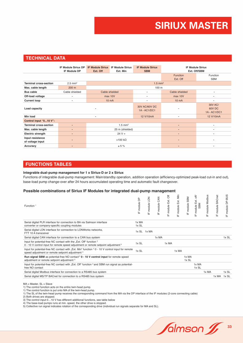
IF Module Siriux Ext. Min
IF Module Siriux SBM
IF Module SiriuxExt. Off/SBM
FunctionExt. Off
FunctionSBM
Terminal cross-section 2.5 mm2 1.5 mm2
Max. cable length 200 m 100 mBus cable Cable shielded Cable shielded - Cable shielded -Off-load voltage - max 10V - max 10V -Current loop - 10 mA - 10 mA -
Load capacity - 30V AC/60V DC1A - AC1/DC1 -
30V AC/60V DC
1A - AC1/DC1Min load - 12 V/10mA - 12 V/10mAControl input “0...10 V”:Terminal cross-section - 1.5 mm2 - -Max. cable length - 25 m (shielded) - -Electric strength - 24 V = - -Input resistanceof voltage input - >100 kΩ - -
Accuracy - ± 5 % - -
FUNCTIONS TABLESIntegrable dual-pump management for 1 x Siriux-D or 2 x SiriuxFunctions of integrable dual-pump management: Main/standby operation, addition operation (efficiency-optimized peak-load cut-in and out), base-load pump change-over after 24 hours accumulated operating time and automatic fault changeover.
Possible combinations of Siriux IF Modules for integrated dual-pump management
Function 1
IF m
odul
e D
P
IF m
odul
e LO
N
IF m
odul
e C
AN
IF m
odul
e Ex
t. O
ff
IF m
odul
e Ex
t. M
in
IF m
odul
e SB
M
IF m
odul
e Ex
t. of
f/SB
M
IF m
odul
e M
odbu
s
IF m
odul
e BA
Cne
t
IF m
odul
e D
P-BU
SSerial digital PLR interface for connection to BA via Salmson interfaceconverter or company-specific coupling modules
1x MA1x SL
Serial digital LON interface for connection to LONWorks networks,FTT 10 A transceiver 1x SL 1x MA
Serial digital CAN interface for connection to a CAN bus system 1x MA 1x SLInput for potential-free NC contact with the „Ext. Off“ function 2
0 - 10 V control input for remote speed adjustment or remote setpoint adjustment 3 1x SL 1x MA
Input for potential-free NC contact with „Ext. Min“ function 4 0 - 10 V control input for remote speed adjustment or remote setpoint adjustment 3 1x SL 1x MA
Run signal SBM as potential-free NO contact 5 0 - 10 V control input for remote speed adjustment or remote setpoint adjustment 3
1x MA1x SL
Input for potential-free NC contact with „Ext. Off“ function 2 and SBM run signal as potential-free NO contact
1x MA1x SL
Serial digital Modbus interface for connection to a RS485 bus system 1x MA 1x SLSerial digital MS/TP BACnet for connection to a RS485 bus system 1x MA 1x SL
MA = Master, SL = Slave1) The control function acts on the entire twin-head pump.1) The control function is put onto MA of the twin-head pump.1) The SL of the twin-head pump receives the corresponding command from the MA via the DP interface of the IF modules (2-core connecting cable)2) Both drives are stopped.3) The control input 0…10 V has different additional functions, see table below4) The base-load pumps runs at min. speed, the other drive is stopped.5) Collective run signal indicates rotation of the corresponding drive (individual run signals separate for MA and SL).
33

SIRIUX MASTER
Functions of analog input “O-10V“ in integrated dual-pump management
FUNCTIONS TABLES
1) The control function acts on the entire twin-head pump.1) The control function is put onto MA of the twin-head pump.1) The SL of the twin-head pump receives the corresponding command from the MA via the DP interface of the IF modules (2-core connecting cable)2) Both drives are stopped.3) The control input 0…10 V has different additional functions, see table below 3) and “High-Efficiency Pumps Planning Guide”.4) The base-load pumps runs at min. speed, the other drive is stopped. 5) Collective run signal indicates rotation of the corresponding drive (individual run signals separate for MA and SL).
1) Observe On/Off switching hysteresis.
Function 1 DP
eludo
m FI
NOL eludo
m FI
ffO .txE eludo
m FI
e CA
Nludo
m FI
niM .txE eludo
m FI
MBS eludom FI
Serial digital PLR interface for connection to BA via Salmson interfaceconverter or company-specific coupling modules
1x MA1x SL
1x SLSerial digital CAN inte rface for connection to a CAN bus system
1x MA
1x MA
1x MA
1x MA
1x SL
1x SL
1x SL
1x MA1x SL
Function 0 - 10 V
Double pump operating mode
Main/ standby
/
Parallel operation
+
Remote speed adjustment (DDC)0 – 1 V: Off 1)
1 – 3 V: min. speed 1)
3 – 10 V: nmin…nmax
- Speed of base-load pump follows the voltage signal- Base-load pump cycling after 24 operating hours
- Both pumps follow the voltage signal at the same speed
Remote setpoint adjustment 0 – 1 V : Off 1)
1 – 3 V: Hmin
3 – 10 V: Hmin…Hmax
- Base-load pump controls the differential pressure- Base-load pump cycling after 24 operating hours
- Efficiency-optimised activation and deactivation of the peak-load pump- Base-load pump cycling after 24 operating hours
Ext.
off/
SBM
eludom FI
1x MA1x SL
MA = Master, SL = Slave
Possible combinations of Siriux IF modules for integrated dual-pump management
Serial digital LON interface for connection to LONWorks networks,FTT 10 A transceiver
Input for potential-free NC contact with the „Ext. Off“ function 2)
0 - 10 V control input for remote speed adjustment or remote
Input for potential-free NC contact with „Ext. Off“ function 2)
and SBM run signal as potential-free NO contact
Input for potential-free NC contact with „Ext. Min“ function 4)
3)
Run signal SBM as potential-free NO contact 5)
0 - 10 V control input for remote speed adjustment or remote setpoint adjustment 3)
setpoint adjustment
0 - 10 V control input for remote speed adjustment or remote 3)setpoint adjustment
TECHNICAL DATA IF MODULE SIRIUX
IF Module Modbus
IF Module BACnet IF MODULE SIRIUX LON
IF Module CAN
Line type Bus cable, twisted in pairsshielded 1 x 2 x 0.5 mm2/ 120 Ω characteristic
impedance (line type B in accordance with TIA 485-A)Line length (max.) 1000 mSpur line Not permissibleTerminal cross-section 1.5 mm²Interface RS485 (TIA-485A), optically insulatedSpeed (velocity) 2400, 9600,19200,38400,115200 kBit/sFormat 8 data bits
no/even/odd parity1 bit stop ( only 2 without parity)
Protocol Modbus RTU
Profile compatible with Digicon Modbus
Line type Bus cable, twisted in pairsshielded 1 x 2 x 0.5 mm2/ 120 Ω characteristic
impedance (line type B in accordance with TIA 485-A)Line length (max.) 1000 mSpur line Not permissibleTerminal cross-section 1.5 mm²Interface RS485 (TIA-485A),
optically insulatedSpeed (velocity) 9600, 19200,38400,76800 kBit/sFormat --
Protocol BACnet MS/TP version 1 revision 4
Profile BACnet Smart Sensor, Smart Actor (B-SS, B-SA)
Line type twisted in pairs, shieldedLine length (max.) 1000 m (bus topology with a max. 3 m spur line)
500 m (free topology, max. 400 m between communicating consumers
Spur line -Terminal cross-section 2.5 mm²Interface FTT 10ASpeed (velocity) 78 kBits/s, constantFormat --
Protocol LONMark Layers 1-6 Interoperability Guidelines 3.2LONmark Application Layer Interoperability Guidelines 3.2
Profile LONMark pump controller 8210_10
Line type CAN bus cable, twisted in pairsshielded 1 x 2 x 0.5 mm2 / 120 Ω characteristic
impedance (line type B in accordance with TIA 485-A)Line length (max.) 200 mSpur line yes, max. 10 m,
total max. 50 mTerminal cross-section 1.5 mm²Interface CAN in accordance with ISO 11898-2,
optically insulatedSpeed (velocity) 125 kBit/s, constantFormat -
Protocol CANopen in accordance with CiA DS301 V 4.02
Profile -
34

SIRIUX MASTER
SALMSON IF MODULE FOR SINGLE AND TWIN-HEAD PUMPS
• 1 x Salmson IF Module Siriux Ext. OffAdditional functions– Input for floating NC contact with «Ext. Off» function
– Contact closed: pump operating under auto control – Contact open: pump stops
– Control input «0 - 10 V» for remote setpoint adjustment or remote speed setting – Remote setpoint adjustment: The setpoint value for integrated dif-
ferential-pressure control is determined for the pump via an analog signal 0 - 10V.
– Remote speed setting: An external controller issues an actuating signal for remote speed setting (DDC operation).
The desired function must be activated at the pump– DP twin-head-pump interface for integrable dual-pump management
of 2 x single or 1 x twin-head pump.
Delivery statusThe terminals of the «Ext. Off» control input are bridged.
Scope of delivery– IF-Module Stratos Ext. Off– EMC screwed connection Pg 9
Ext.off
DP
L N PE SSM1~230 V
SiriuxIF Module Siriux Ext. off
0...10V
Remote control– Remote potentialfree contact (input): Open contact: Pump on Closed contact: Pump "Off"
– For remote actuation, remove bridge
1x IF Module Siriux Ext. Off1x IF Module Siriux Ext. Off (master) 1x IF Module Siriux DP (slave)
DP
L N PE SSM1~230 V
Siriux DSiriux
Siriux DSiriux
IF Module Siriux Ext. off
Master
DP
DP
L N PE SSM1~230 V
Slave
IF Module Siriux DP
Connecting cable, min. 2 x 0,75 mm2, lock-protected
Remote contact– Ext. potential-free contact (Input): Closed contacts: Twin-head pump on Open contacts: Twin-head pump "off"– For remote actuation, remove bridge
Ext.off
DP
0...10V
• 1 x Salmson IF Module Siriux Ext. Off (master) • 1 x Salmson IF Module Siriux DP (slave)
Functions as described at left, plus:
Double pump DP interface for the optional integration of a dualpump management system of 1 x double pump or 2 x single pumps,optionally with the following functions:– Main/standby operation for automatic fault-actuated switchover tothe standby pump and automatic pump alteration after 24 hrs runningtime
– Parallel operation for efficiency-optimised activation and deactiva-tion of the peak-load pump and automatic fault-actuated switchover to standby pump
The Ext. Off function and the control input 0 – 10 V act on bothpumps.
35

SIRIUX MASTER
SALMSON IF MODULE FOR SINGLE AND TWIN-HEAD PUMPS
• 1 x Salmson IF Module Siriux Ext. MinAdditional functions– Input for floating NC contact with «Ext. Min» function (setback ope-
ration without autopilot)– Contact closed: pump operating under auto control – Contact open: pump runs at fixed min. speed (cable shielded)
– Control input «0 - 10 V» for remote setpoint adjustment or remote speed setting – Remote setpoint adjustment: The setpoint value for integrated dif-ferential-pressure control is determined for the pump via an analog signal 0 - 10 V . – Remote speed setting: An external controller issues an actuating signal for remote speed setting (DDC operation).The desired function must be activated at the pump
–DP twin-head-pump interface for integrable dual-pump management of 2 single or 1 twin-head pump (see Siriux-IF-Modules for Twin-Head Pumps)
Delivery statusThe terminals of the «Ext. Min» control input are bridged.
Scope of delivery– IF-Module Stratos Ext. Min– EMC screwed connection Pg 9
Remote control– Ext. potential-free contact (input): Closed contacts: Pump on Open contacts: Pump "Min"
– For remote actuation, remove bridge
Ext.Min
DP
L N PE SSM1~230 V
SiriuxIF Module Siriux Ext. Min
0...10V
• 1 x Salmson IF Module Siriux Ext. Min (master) • 1 x Salmson IF Module Siriux DP (slave)
Functions as described at left, plus:
Double pump DP interface for the optional integration of a dualpump management system of 1 x double pump or 2 x single pumps,optionally with the following functions:– Main/standby operation for automatic fault-actuated switchover tothe standby pump and automatic pump alteration after 24 hrs runningtime
– Parallel operation for efficiency-optimised activation and deactiva-tion of the peak-load pump and automatic fault-actuated switchover to standby pump
The Ext. Min function and the control input 0 – 10 V act on bothpumps.
1x IF Module Siriux Ext. Min1x IF Module Siriux Ext. Min (master) 1x IF Module Siriux DP (slave)
DP
L N PE SSM1~230 V
Siriux DSiriux
Siriux DSiriux
IF Module Siriux Ext. Min
Master
DP
DP
L N PE SSM1~230 V
Slave
IF ModuleSiriux DP
Connecting cable, min. 2 x 0,75 mm2, lock-protected
Remote contact– Ext. potential-free contact (Input): Closed contacts: Twin-head pump on Open contactst: Twin-head pum "off"– For remote actuation, remove bridge
Ext.Min
DP
0...10V
36
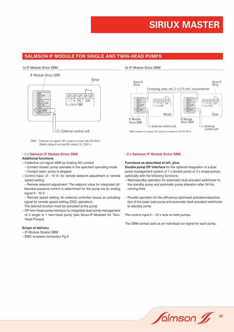
SIRIUX MASTER
SALMSON IF MODULE FOR SINGLE AND TWIN-HEAD PUMPS
1x IF Module Siriux SBM 2x IF Module Siriux SBM
0...10V L N PE SSM
1~230 V
Siriux DSiriux
Siriux DSiriux
IF Module Siriux SBM
Master
L N PE SSM1~230 V
Slave
IF Module Siriux SBM
Connecting cable, min. 2 x 0,75 mm2, lock-protected
External control unit
SBM*
DP
External control unit
*SBM: Collective run signals, NO contact in compliance with VDI 3814
0...10V 0...10V
SBM*
DP
0...10V
• 1 x Salmson IF Module Siriux SBMAdditional functions– Collective run signal SBM as floating NO contact
– Contact closed: pump operates in the specified operating mode – Contact open: pump is stopped
– Control input «0 - 10 V» for remote setpoint adjustment or remote speed setting – Remote setpoint adjustment: The setpoint value for integrated dif-ferential-pressure control is determined for the pump via an analog signal 0 - 10 V. – Remote speed setting: An external controller issues an actuating signal for remote speed setting (DDC operation).The desired function must be activated at the pump
– DP twin-head-pump interface for integrable dual-pump management of 2 single or 1 twin-head pump (see Siriux-IF-Modules for Twin-Head Pumps)
Scope of delivery– IF-Module Stratos SBM– EMC screwed connection Pg 9
External control unit
SBM*
DP
L N PE SSM1~230 V
IF Module Siriux SBM
*SBM: Collective run signals, NO contact in compl. with VDI 3814(Switch rating of vol.-free NO contact 1A, 250V~)
0...10V
Siriux
• 2 x Salmson IF Module Siriux SBM
Functions as described at left, plus:Double pump DP interface for the optional integration of a dualpump management system of 1 x double pump or 2 x single pumps,optionally with the following functions:– Main/standby operation for automatic fault-actuated switchover to
the standby pump and automatic pump alteration after 24 hrs running time
– Parallel operation for the efficiency-optimised activation/deactiva-tion of the peak load pump and automatic fault-actuated switchover to standby pump
The control input 0 – 10 V acts on both pumps.
The SBM contact acts as an individual run signal for each pump.
37

SIRIUX MASTER
SALMSON IF MODULE FOR SINGLE AND TWIN-HEAD PUMPS
• 1 x Salmson IF Module Siriux Ext. off/SBMAdditional functions– Input for potential-free NC contact with the Ext. Off function
– Contact closed: Pump running in auto control mode – Contact open: Pump is not running.
– Collective run signal SBM as potential-free NO contact – Contact closed: Pump is running in the specified operating mode – Contact open: Pump is not running
– Double pump DP interface for integrated dual pump management of 2 x single pumps or 1 x double pump (see Siriux IF-Modules for double pumps)
Delivery statusThe terminals of the «Ext. off.» control input are bridged.
Scope of delivery– IF-Module Ext. Off/SBM– EMC screwed connection Pg 9
DP
SBM*
Ext. Off
Remote control (shielded cable)* Remote potentialfree contact Open contact: Pump on Closed contact: Pump "Off"* For remote actuation, remove bridge
* SBM: Collective run signal, normally open contact according to VDI 3814
SiriuxIF ModuleSiriux Ext. Off / SBM
L N PE SSM1~230V
1x IF Module Siriux Ext.Off/SBM 2x IF Module Siriux Ext.Off/SBM
DP
SBM*
Ext. Off
Remote contact (shielded cable)– Ext. potential-free contact (Input): Closed contacts: Twin-head pump on Open contacts: Twin-head pump "off"– For remote actuation, remove bridge
External control unit* SBM: Collective run signal,
normally open contact accordingto VDI 3814
DP
SBM*
Ext. Off
IF moduleSiriux Ext. Off / SBM
External control unit
Connecting cable, min. 2 x 0.75 mm 2, lock-protectedSiriux DSiriux
Siriux DSiriux
IF Module Siriux Ext. Off / SBM
Master Slave
L N PE SSM1~230V
L N PE SSM1~230V
• 2 x Salmson IF Module Siriux Ext. off/SBM
Functions as described at left, plusDouble pump DP interface for the optional integration of a dualpump management system of 1 x double pump or 2 x single pumps,optionally with the following functions:– Main/standby operation for automatic fault-actuated switchover to
the standby pump and automatic pump alteration after 24 hrs running time
– Parallel operation for the efficiency-optimised activation/deactiva-tion of the peak load pump and automatic fault-actuated switchover to standby pump
The Ext Off function acts on both pumps.
The SBM contact acts as an individual run signal for each pump.
38

SIRIUX MASTER
SALMSON IF MODULE FOR SINGLE AND TWIN-HEAD PUMPS
1x IF Module Siriux LON1x IF Module Siriux LON (master) 1x IF Module Siriux DP (slave)
• 1 x Salmson IF Module Siriux LONAdditional functions– Serial digital LON interface for connection to LONWORKS networks.– Transfer of the following data items as control commands to the pump:
– Control mode– Delivery head/speed setpoint – Pump On/Off– Setback operation– Control mode– Data from external sensors – Transfer of the following data items as signals from the pump:
– Actual delivery head value– Actual volume flow value– Actual consumption value– Actual output value– Actual motor current value– Operating hours– Actual speed value– Detailed fault signals– Status signals
DP double pump interface (see details alongside)
Documentation to download– LON support files:– Download application via network: *.NXE / *.APB– External interface files: *.XIF / *.XFB– Device resource files: *.ENU / *.FMT / *.FPT / *.TYPhttp://www.salmson.com
Scope of delivery– IF-Module Stratos LON– EMC screwed connection pg 7 and pg 9– Sticker with Neuron-ID to peel off
Delivery statusThe IF-Module LON is supplied as “Application unconfigured” in accor-dance with the LONMark Application Layer Interoperability Guidelines
LONWORKS network
LON
DP
L N PE SSM1~230 V
SiriuxIF Module Siriux LON
LON
DP
L N PE 1~230 V PLR
DP
Master
L N PE 1~230 V
Slave
SSMSSM
SiriuxSiriux D
SiriuxSiriux D
LONWorks network(shielded cable)
IF-moduleSiriux LON
Connecting cable, min. 2 x 0.75 mm2, lock-protected
IF-moduleSiriux DP
• 1 x Salmson IF Module Siriux LON (master) • 1 x Salmson IF Module Siriux DP (slave)
Functions as described at left, plus:
Double pump DP interface for the optional integration of a dualpump management system of 1 x double pump or 2 x single pumps,optionally with the following functions:– Main/standby operation for automatic fault-actuated switchover tothe standby pump and automatic pump alteration after 24 hrs runningtime
– Parallel operation for efficiency-optimised activation and deactiva-tion of the peak-load pump and automatic fault-actuated switchover to standby pump
In the LONWorks network, data items are transmitted for the doublepump as a complete unit; there is no differentiation between masterand slave.
39

SIRIUX MASTER
SALMSON IF MODULE FOR SINGLE AND TWIN-HEAD PUMPS
• 1 x Salmson IF Module Siriux CAN (master) • 1 x Salmson IF Module Siriux DP-Bus (slave)
Functions as described at left, plus:
Double pump DP interface for the optional integration of a dualpump management system of 1 x double pump or 2 x single pumps,optionally with the following functions:– Main/standby operation for automatic fault-actuated switchover tothe standby pump and automatic pump alteration after 24 hrs runningtime
– Parallel operation for efficiency-optimised activation and deactiva-tion of the peak-load pump and automatic fault-actuated switchover to standby pump
1x IF Module Siriux CAN1x IF Module Siriux CAN (master) 1x IF Module Siriux DP-Bus (slave)
• 1 x Salmson IF Module Siriux CANAdditional functionsSerial, digital CANopen interface for connection to a CAN bus system.– Transfer of the following data items as control commands to thepump:
– Control mode – Delivery head/speed setpoint– Pump On/Off – Setback operation
– Transfer of the following data items as signals from the pump:– Actual delivery head value– Actual volume flow value– Actual consumption value– Actual output value– Actual motor current value– Operating hours– Actual speed value– Detailed fault signals– Status signals
DP double pump interface(see details alongside)
Documentation to download– CAN specification for IF-Module– CANopen .eds filehttp://www.salmson.com
Scope of delivery– IF-Module Stratos CAN– EMC screwed connection pg 7 and pg 9– Sticker for BUS address
DP
CAN-LCAN-HCAN-LCAN-H WH
BNWHBN
L N PE SSM1~230V
IF module Siriux CAN Siriux
CAN
CAN
Master Slave
IF module Siriux CAN IF module SiriuxDP-Bus
DP
CAN-LCAN-HCAN-LCAN-H
RDBKBUWHBNWHWH
BN
BKRD
L N PE SSM1~230V
L N PE SSM1~230V
CAN CAN
BUWH
min. 2 x 2 x 0,22 mm2 Z=120 Ω
DP
PLR
CAN-LCAN-H
SiriuxSiriux
DP
CAN-LCAN-HCAN-LCAN-H WH
BNWHBN
L N PE SSM1~230V
IF module Siriux CAN Siriux
CAN
CAN
Master Slave
IF module Siriux CAN IF module SiriuxDP-Bus
DP
CAN-LCAN-HCAN-LCAN-H
RDBKBUWHBNWHWH
BN
BKRD
L N PE SSM1~230V
L N PE SSM1~230V
CAN CAN
BUWH
min. 2 x 2 x 0,22 mm2 Z=120 Ω
DP
PLR
CAN-LCAN-H
SiriuxSiriux
40

SIRIUX MASTER
SALMSON IF MODULE FOR SINGLE AND TWIN-HEAD PUMPS
1x IF Module Siriux Modbus1x IF Module Siriux Modbus (master) 1x IF Module Siriux DP-Bus (slave)
• 1 x Salmson IF Module Siriux ModbusAdditional functionsSerial, digital Modbus RTU interface for connection to building automation (BA) via RS485. Transfer of the following data items as control commands to thepump:
– Control mode– Delivery head/speed setpoint– Pump On/Off– Setback operation
Transfer of the following data items as signals from the pump:– Actual delivery head value– Actual volume flow value– Actual consumption value– Actual output value– Actual motor current value– Operating hours– Actual speed value– Detailed fault signals– Status signals
DP double pump interface(see details alongside)
Documentation to download– Modbus specification for IF– Modulehttp://www.salmson.com
Scope of delivery– IF Module Siriux Modbus– EMC screwed connection pg 7 and pg 9– Sticker for BUS address
• 1 x Salmson IF Module Siriux Modbus (master)• 1 x Salmson IF Module Siriux DP-Bus (slave)
Functions as described at left, plus:Double pump DP interface for the optional integration of a dualpump management system of 1 x double pump or 2 x single pumps,optionally with the following functions:– Main/standby operation for automatic fault-actuated switchover tothe standby pump and automatic pump alteration after 24 hrs runningtime
– Parallel operation for efficiency-optimised activation and deactiva-tion of the peak-load pump and automatic fault-actuated switchover to standby pump
DP
A(-)B(+)A(-)B(+)
WHBNWHBN
L N PE SSM1~230V
RS485
RS485
DP
B(+)A(-)B(+)A(-)
RDBKBUWHBNWHWH
BNWHBUBKRD
L N PE SSM
Master Slave
1~230VL N PE SSM
1~230V
RS485 RS485
min. 2 x 2 x 0,22 mm2 Z=120 Ohm
DP
4321
IF module Siriux Modbus
IF module Siriux Modbus
IF module Siriux DP-Bus
Siriux Siriux Siriux
DP
A(-)B(+)A(-)B(+)
WHBNWHBN
L N PE SSM1~230V
RS485
RS485
DP
B(+)A(-)B(+)A(-)
RDBKBUWHBNWHWH
BNWHBUBKRD
L N PE SSM
Master Slave
1~230VL N PE SSM
1~230V
RS485 RS485
min. 2 x 2 x 0,22 mm2 Z=120 Ohm
DP
4321
IF module Siriux Modbus
IF module Siriux Modbus
IF module Siriux DP-Bus
Siriux Siriux Siriux
41

SIRIUX MASTER
SALMSON IF MODULE FOR SINGLE AND TWIN-HEAD PUMPS
1x IF Module Siriux BACnet1x IF Module Siriux BACnet (master) 1x IF Module Siriux DP-Bus (slave)
• 1 x Salmson IF Module Siriux BACnetAdditional functionsSerial, digital BACnet MS/TP interface for connection to buildingautomation (BA) via RS485.. Transfer of the following data items as control commands to thepump: – Control mode – Delivery head/speed setpoint – Pump On/Off – Setback operationTransfer of the following data items as signals from the pump: – Actual delivery head value – Actual volume flow value – Actual consumption value – Actual output value – Actual motor current value – Operating hours – Actual speed value – Detailed fault signals – Status signals
DP double pump interface(see details alongside)
Documentation to download – BACnet PICS and list of data itemshttp://www.salmson.com
Scope of delivery – IF Module Siriux BACnet – EMC screwed connection pg 7 and pg 9 – Sticker for BUS address
DP
A(-)B(+)A(-)B(+)
WHBNWHBN
L N PE SSM1~230V
RS485
RS485
Siriux Siriux SiriuxIF moduleSiriux BACnet
IF moduleSiriux BACnet
IF moduleSiriux DP-Bus
DP
B(+)A(-)B(+)A(-)
RDBKBUWHBNWHWH
BNWHBUBKRD
L N PE SSM
Master Slave
1~230VL N PE SSM
1~230V
RS485 RS485
min. 2 x 2 x 0,22 mm2 Z=120 Ohm
DP
4321
DP
A(-)B(+)A(-)B(+)
WHBNWHBN
L N PE SSM1~230V
RS485
RS485
Siriux Siriux SiriuxIF moduleSiriux BACnet
IF moduleSiriux BACnet
IF moduleSiriux DP-Bus
DP
B(+)A(-)B(+)A(-)
RDBKBUWHBNWHWH
BNWHBUBKRD
L N PE SSM
Master Slave
1~230VL N PE SSM
1~230V
RS485 RS485
min. 2 x 2 x 0,22 mm2 Z=120 Ohm
DP
4321
• 1 x Salmson IF Module Siriux BACnet (master)• 1 x Salmson IF Module Siriux DP-Bus (slave)
Functions as described at left, plus:Double pump DP interface for the optional integration of a dualpump management system of 1 x double pump or 2 x single pumps,optionally with the following functions:– Main/standby operation for automatic fault-actuated switchover tothe standby pump and automatic pump alteration after 24 hrs runningtime
– Parallel operation for efficiency-optimised activation and deactiva-tion of the peak-load pump and automatic fault-actuated switchover to standby pump
42
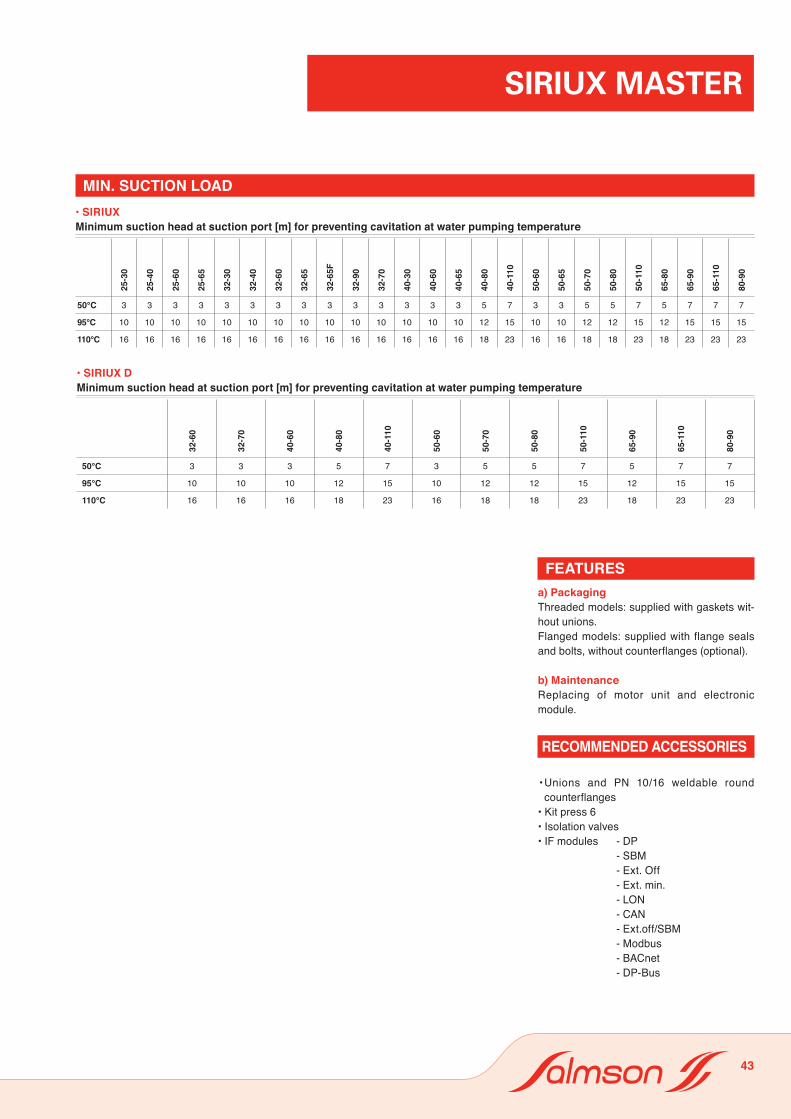
• SIRIUXPression minimale à l’aspiration [m] pour éviter la cavitation pour température de fluide
25-3
0
25-4
0
25-6
0
25-6
5
32-3
0
32-4
0
32-6
0
32-6
5
32-6
5F
32-9
0
32-7
0
40-3
0
40-6
0
40-6
5
40-8
0
40-1
10
50-6
0
50-6
5
50-7
0
50-8
0
50-1
10
65-8
0
65-9
0
65-1
10
80-9
0
50°C 3 3 3 3 3 3 3 3 3 3 3 3 3 3 5 7 3 3 5 5 7 5 7 7 7
95°C 10 10 10 10 10 10 10 10 10 10 10 10 10 10 12 15 10 10 12 12 15 12 15 15 15
110°C 16 16 16 16 16 16 16 16 16 16 16 16 16 16 18 23 16 16 18 18 23 18 23 23 23
• SIRIUX DPression minimale à l’aspiration [m] pour éviter la cavitation pour température de fluide
32-6
0
32-7
0
40-6
0
40-8
0
40-1
10
50-6
0
50-7
0
50-8
0
50-1
10
65-9
0
65-1
10
80-9
0
50°C 3 3 3 5 7 3 5 5 7 5 7 7
95°C 10 10 10 12 15 10 12 12 15 12 15 15
110°C 16 16 16 18 23 16 18 18 23 18 23 23
SIRIUX MASTER
FEATURESa) PackagingThreaded models: supplied with gaskets wit-hout unions.Flanged models: supplied with flange seals and bolts, without counterflanges (optional).
b) MaintenanceReplacing of motor unit and electronic module.
• Unions and PN 10/16 weldable round counterflanges
• Kit press 6• Isolation valves• IF modules - DP - SBM - Ext. Off - Ext. min. - LON - CAN - Ext.off/SBM - Modbus - BACnet - DP-Bus
RECOMMENDED ACCESSORIES
MIN. SUCTION LOAD• SIRIUXMinimum suction head at suction port [m] for preventing cavitation at water pumping temperature
• SIRIUX DMinimum suction head at suction port [m] for preventing cavitation at water pumping temperature
43