Embed Size (px)
Citation preview

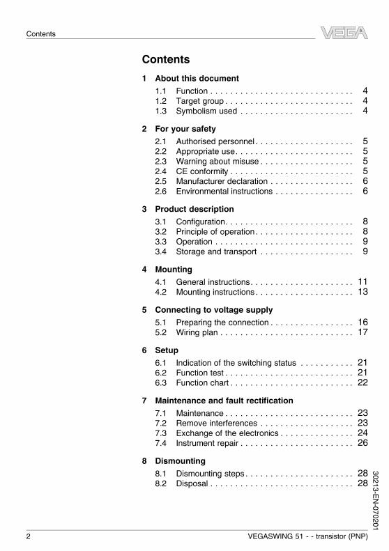
Operating InstructionsVEGASWING 51- transistor (PNP)
Contents1 About this document
1.1 Function . . . . . . . . . . . . . . . . . . . . . . . . . . . . . 41.2 Target group . . . . . . . . . . . . . . . . . . . . . . . . . . 41.3 Symbolism used . . . . . . . . . . . . . . . . . . . . . . . 4
2 For your safety2.1 Authorised personnel . . . . . . . . . . . . . . . . . . . . 52.2 Appropriate use. . . . . . . . . . . . . . . . . . . . . . . . 52.3 Warning about misuse . . . . . . . . . . . . . . . . . . . 52.4 CE conformity . . . . . . . . . . . . . . . . . . . . . . . . . 52.5 Manufacturer declaration . . . . . . . . . . . . . . . . . 62.6 Environmental instructions . . . . . . . . . . . . . . . . 6
3 Product description3.1 Configuration. . . . . . . . . . . . . . . . . . . . . . . . . . 83.2 Principle of operation . . . . . . . . . . . . . . . . . . . . 83.3 Operation . . . . . . . . . . . . . . . . . . . . . . . . . . . . 93.4 Storage and transport . . . . . . . . . . . . . . . . . . . 9
4 Mounting4.1 General instructions. . . . . . . . . . . . . . . . . . . . . 114.2 Mounting instructions . . . . . . . . . . . . . . . . . . . . 13
5 Connecting to voltage supply5.1 Preparing the connection . . . . . . . . . . . . . . . . . 165.2 Wiring plan . . . . . . . . . . . . . . . . . . . . . . . . . . . 17
6 Setup6.1 Indication of the switching status . . . . . . . . . . . 216.2 Function test . . . . . . . . . . . . . . . . . . . . . . . . . . 216.3 Function chart . . . . . . . . . . . . . . . . . . . . . . . . . 22
7 Maintenance and fault rectification7.1 Maintenance . . . . . . . . . . . . . . . . . . . . . . . . . . 237.2 Remove interferences . . . . . . . . . . . . . . . . . . . 237.3 Exchange of the electronics . . . . . . . . . . . . . . . 247.4 Instrument repair . . . . . . . . . . . . . . . . . . . . . . . 26
8 Dismounting8.1 Dismounting steps . . . . . . . . . . . . . . . . . . . . . . 288.2 Disposal . . . . . . . . . . . . . . . . . . . . . . . . . . . . . 28
2 VEGASWING 51 - - transistor (PNP)
Contents
30213-EN-070201
9 Supplement9.1 Technical data. . . . . . . . . . . . . . . . . . . . . . . . . 299.2 Dimensions . . . . . . . . . . . . . . . . . . . . . . . . . . . 329.3 Industrial property rights. . . . . . . . . . . . . . . . . . 359.4 Trademark . . . . . . . . . . . . . . . . . . . . . . . . . . . 35
VEGASWING 51 - - transistor (PNP) 3
Contents
3021
3-EN-
0702
01
1 About this document1.1 FunctionThis operating instructions manual has all the information youneed for quick setup and safe operation. Please read thismanual before you start setup.
1.2 Target groupThis operating instructions manual is directed to trained,qualified personnel. The contents of this manual should bemade available to these personnel and put into practice bythem.
1.3 Symbolism usedInformation, tip, noteThis symbol indicates helpful additional information.
Caution: If this warning is ignored, faults ormalfunctions can result.Warning: If this warning is ignored, injury to persons and/orserious damage to the instrument can result.Danger: If this warning is ignored, serious injury to personsand/or destruction of the instrument can result.
Ex applicationsThis symbol indicates special instructions for Ex applications.
l ListThe dot set in front indicates a list with no implied sequence.
à ActionThis arrow indicates a single action.
1 SequenceNumbers set in front indicate successive steps in a procedure.
4 VEGASWING 51 - - transistor (PNP)
About this document
30213-EN-070201
2 For your safety2.1 Authorised personnelAll operations described in this operating instructions manualmust be carried out only by trained specialist personnelauthorised by the operator. For safety and warranty reasons,any internal work on the instruments must be carried out onlyby personnel authorised by the manufacturer.
2.2 Appropriate useVEGASWING 51 is a sensor for level detection.Detailed information on the application range of VEGASWING51 is available in chapter "Product description".
2.3 Warning about misuseInappropriate or incorrect use of the instrument can give rise toapplication-specific hazards, e.g. vessel overfill or damage tosystem components through incorrect mounting or adjustment.
2.4 General safety instructionsVEGASWING 51 is a high-tech instrument requiring the strictobservance of standard regulations and guidelines. The usermust take note of the safety instructions in this operatinginstructions manual, the country-specific installation standards(e.g. the VDE regulations in Germany) as well as all prevailingsafety regulations and accident prevention rules.
2.5 CE conformityVEGASWING 51 is in CE conformity with EMC (89/336/EWG),fulfils NAMUR recommendationNE 21 and NE 23 and is in CEconformity with NSR (73/23/EWG).Conformity has been judged according to the followingstandards:l EMC:
- Emission EN 61326: 1997 (class B)- Susceptibility EN 61326: 1997/A1:1998
l LVD: EN 61010-1: 2001
VEGASWING 51 - - transistor (PNP) 5
For your safety
3021
3-EN-
0702
01
2.6 Manufacturer declarationIn conformity with DIN EN 60079-14/2004, para. 5.2.3, pointc1, VEGASWING 51 is suitable for use in zone 2.The operator must use the instrument as it was intended to beused and follow the specifications of the following documents:l this operating instructions manuall this manufacturer declaration (24625)l the applicable installation regulationsMax. increase of the surface temperature during operation:82 K (individual components in the instrument)With an ambient temperature of 70 °C (158 °F) on the housingand a process temperature of 70 °C (158 °F), the max. ambienttemperature during operation is 135 °C (275 °F).Measures to maintain explosion protection during operation:l Operate the instrument in the range of the specified
electrical limit values. Permissible supply voltage: see"Technical data"
l Mount and operate the instrument in such a way thatignition danger by electrostatic charge is not expected.
l Make sure that no explosive atmosphere exists when theplug of the connection cable is pulled or plugged
l Make sure that the cable gland is tight and strain-relieved.The outer diameter of the connection cable must beadapted to the cable gland. Tighten the pressure screw ofthe cable gland carefully.
l The surface temperature of the housing must not exceedthe ignition temperature of the surrounding explosiveatmosphere
This instrument was assessed by a person who fulfils the DINEN 60079-14 requirements.
2.7 Environmental instructionsProtection of the environment is one of our most importantduties. That is why we have introduced an environmentmanagement system with the goal of continuously improvingcompany environmental protection. The environment man-agement system is certified according to DIN EN ISO 14001.Please help us fulfil this obligation by observing the environ-mental instructions in this manual:l Chapter "Storage and transport"
6 VEGASWING 51 - - transistor (PNP)
For your safety
30213-EN-070201
l Chapter "Disposal"
VEGASWING 51 - - transistor (PNP) 7
For your safety
3021
3-EN-
0702
01
3 Product description3.1 ConfigurationThe scope of delivery encompasses:l VEGASWING 51 level sensorl Test magnetl Documentation
- this operating instructions manual- if necessary, certificates
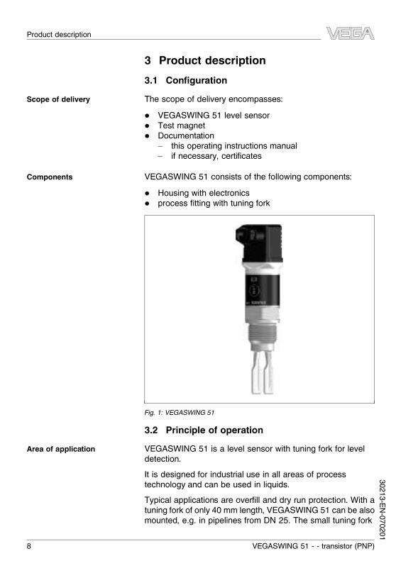
VEGASWING 51 consists of the following components:l Housing with electronicsl process fitting with tuning fork
Fig. 1: VEGASWING 51
3.2 Principle of operationVEGASWING 51 is a level sensor with tuning fork for leveldetection.It is designed for industrial use in all areas of processtechnology and can be used in liquids.Typical applications are overfill and dry run protection. With atuning fork of only 40 mm length, VEGASWING 51 can be alsomounted, e.g. in pipelines from DN 25. The small tuning fork
Scope of delivery
Components
Area of application
8 VEGASWING 51 - - transistor (PNP)
Product description
30213-EN-070201
allows use in vessels, tanks and pipes. Thanks to its simpleand robust measuring system, VEGASWING 51 is virtuallyunaffected by the chemical and physical properties of theliquid.It functions even under difficult conditions such as turbulence,air bubbles, foam generation, buildup, strong external vibrationor changing products.Fault monitoringThe electronics module of VEGASWING 51 continuouslymonitors via frequency evaluation the following criteria:l Strong corrosion or damage on the tuning forkl loss of vibrationl Line break to the piezo driveIf a malfunction is detected or in case of power failure, theelectronics takes on a defined switching condition, i.e. theoutput transistor blocks (safe condition).The tuning fork is piezoelectrically energised and vibrates at itsmechanical resonance frequency of approx. 1200 Hz. Thepiezos are fixed mechanically and are hence not subject totemperature shock limitations. The frequency changes whenthe tuning fork is covered by the medium. This change isdetected by the integrated oscillator and converted into aswitching command.VEGASWING 51 is a compact instrument, i.e. it can beoperated without external evaluation system. The integratedelectronics evaluates the level signal and outputs a switchingsignal. With this switching signal, a connected device can beoperated directly (e.g. a warning system, a PLC, a pump etc.).The data for power supply are stated in chapter "Technicaldata" in the "Supplement".
3.3 OperationThe switching status of VEGASWING 51 can be checked withclosed housing (signal lamp). Products with a density >0.7 g/cm³ (>0.025 lbs/in³) can be detected.
3.4 Storage and transportYour instrument was protected by packaging during transport.Its capacity to handle normal loads during transport is assuredby a test according to DIN EN 24180.
Functional principle
Supply
Packaging
VEGASWING 51 - - transistor (PNP) 9
Product description
3021
3-EN-
0702
01
The packaging of standard instruments consists of environ-ment-friendly, recyclable cardboard. For special versions, PEfoam or PE foil is also used. Dispose of the packaging materialvia specialised recycling companies.
l Storage and transport temperature see "Supplement -Technical data - Ambient conditions"
l Relative humidity 20 … 85 %
Storage and transport tem-perature
10 VEGASWING 51 - - transistor (PNP)
Product description
30213-EN-070201
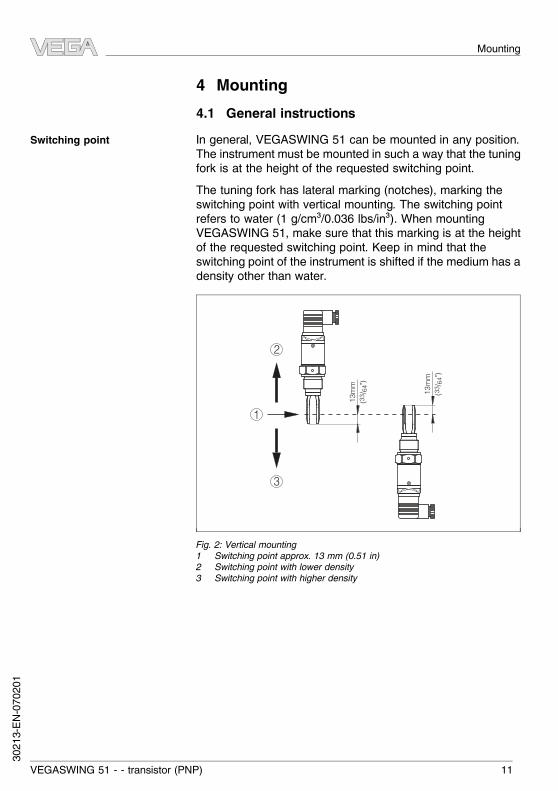
4 Mounting4.1 General instructionsIn general, VEGASWING 51 can be mounted in any position.The instrument must be mounted in such a way that the tuningfork is at the height of the requested switching point.The tuning fork has lateral marking (notches), marking theswitching point with vertical mounting. The switching pointrefers to water (1 g/cm³/0.036 lbs/in³). When mountingVEGASWING 51, make sure that this marking is at the heightof the requested switching point. Keep in mind that theswitching point of the instrument is shifted if the medium has adensity other than water.
2
3
113
mm
(3
3 /64
")
13m
m
(33 /
64")
Fig. 2: Vertical mounting1 Switching point approx. 13 mm (0.51 in)2 Switching point with lower density3 Switching point with higher density
Switching point
VEGASWING 51 - - transistor (PNP) 11
Mounting
3021
3-EN-
0702
01
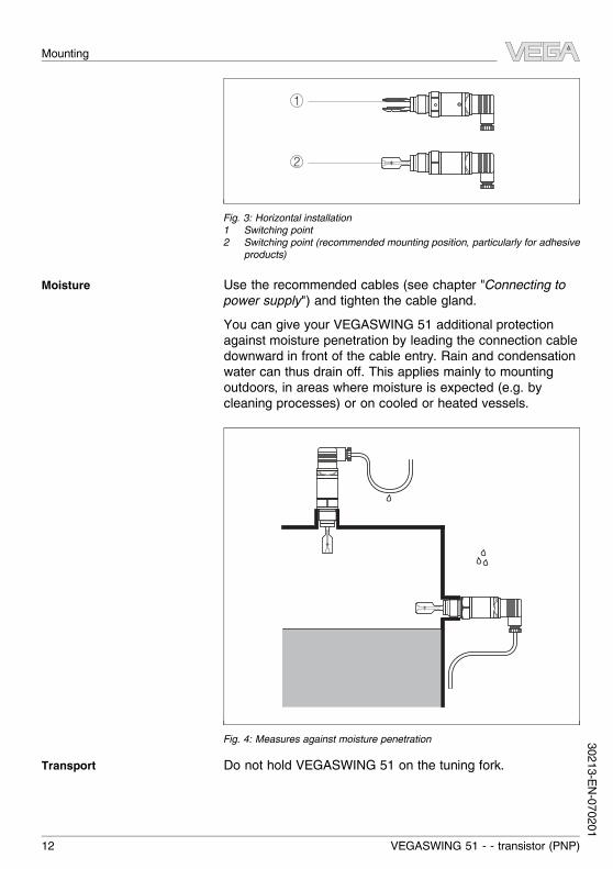
1
2
Fig. 3: Horizontal installation1 Switching point2 Switching point (recommended mounting position, particularly for adhesive
products)
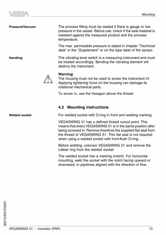
Use the recommended cables (see chapter "Connecting topower supply") and tighten the cable gland.You can give your VEGASWING 51 additional protectionagainst moisture penetration by leading the connection cabledownward in front of the cable entry. Rain and condensationwater can thus drain off. This applies mainly to mountingoutdoors, in areas where moisture is expected (e.g. bycleaning processes) or on cooled or heated vessels.
Fig. 4: Measures against moisture penetration
Do not hold VEGASWING 51 on the tuning fork.
Moisture
Transport
12 VEGASWING 51 - - transistor (PNP)
Mounting
30213-EN-070201
The process fitting must be sealed if there is gauge or lowpressure in the vessel. Before use, check if the seal material isresistant against the measured product and the processtemperature.The max. permissible pressure is stated in chapter "Technicaldata" in the "Supplement" or on the type label of the sensor.The vibrating level switch is a measuring instrument and mustbe treated accordingly. Bending the vibrating element willdestroy the instrument.
Warning:The housing must not be used to screw the instrument in!Applying tightening force on the housing can damage itsrotational mechanical parts.To screw in, use the hexagon above the thread.
4.2 Mounting instructionsFor welded socket with O-ring in front and welding marking.VEGASWING 51 has a defined thread runout point. Thismeans that every VEGASWING 51 is in the same position afterbeing screwed in. Remove therefore the supplied flat seal fromthe thread of VEGASWING 51. This flat seal is not requiredwhen using a welded socket with front-flush O-ring.Before welding, unscrew VEGASWING 51 and remove therubber ring from the welded socket.The welded socket has a marking (notch). For horizontalmounting, weld the socket with the notch facing upward ordownward; in pipelines aligned with the direction of flow.
Pressure/Vacuum
Handling
Welded socket
VEGASWING 51 - - transistor (PNP) 13
Mounting
3021
3-EN-
0702
01
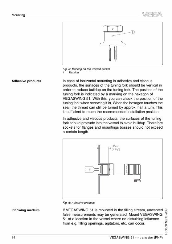
1
Fig. 5: Marking on the welded socket1 Marking
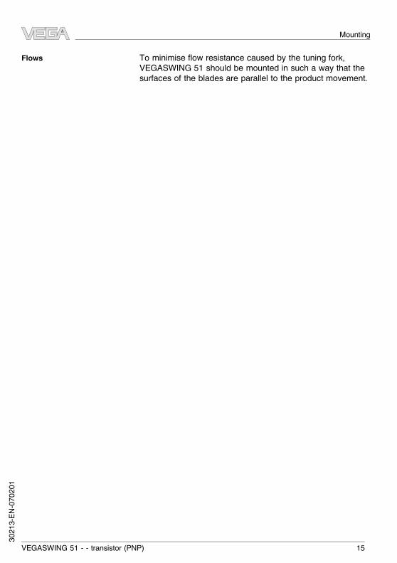
In case of horizontal mounting in adhesive and viscousproducts, the surfaces of the tuning fork should be vertical inorder to reduce buildup on the tuning fork. The position of thetuning fork is indicated by a marking on the hexagon ofVEGASWING 51. With this, you can check the position of thetuning fork when screwing it in.When the hexagon touches theseal, the thread can still be turned by approx. half a turn. Thisis sufficient to reach the recommended installation position.In adhesive and viscous products, the surfaces of the tuningfork should protrude into the vessel to avoid buildup. Thereforesockets for flanges and mountings bosses should not exceeda certain length.
30mm (1 3/16")
Fig. 6: Adhesive products
If VEGASWING 51 is mounted in the filling stream, unwantedfalse measurements may be generated. Mount VEGASWING51 at a location in the vessel where no disturbing influencefrom e.g. filling openings, agitators, etc. can occur.
Adhesive products
Inflowing medium
14 VEGASWING 51 - - transistor (PNP)
Mounting
30213-EN-070201
To minimise flow resistance caused by the tuning fork,VEGASWING 51 should be mounted in such a way that thesurfaces of the blades are parallel to the product movement.
Flows
VEGASWING 51 - - transistor (PNP) 15
Mounting
3021
3-EN-
0702
01
5 Connecting to voltage supply5.1 Preparing the connectionGenerally note the following safety instructions:l Connect only in the complete absence of line voltageVEGASWING 51 is connected with standard cable with roundcross section. Depending on the plug connection, you have toselect the outer diameter of the cable respectively so that theseal effect of the cable gland is ensured.l Valve plug DIN 43650, ø 4.5 … 7 mml Valve plug DIN 43650 with IDC method of termination,
ø 5.5 … 8 mmUse cable with a round wire cross section and tighten thecable gland.When mounting outdoors, on cooled vessels or in humidareas, in which cleaning is carried out e.g. with steam or highpressure, it is particularly important to seal the cable gland.
Note safety instructions
Selecting connection cable
Cable glands
16 VEGASWING 51 - - transistor (PNP)
Connecting to voltage supply
30213-EN-070201
5.2 Wiring plan
1 2 3
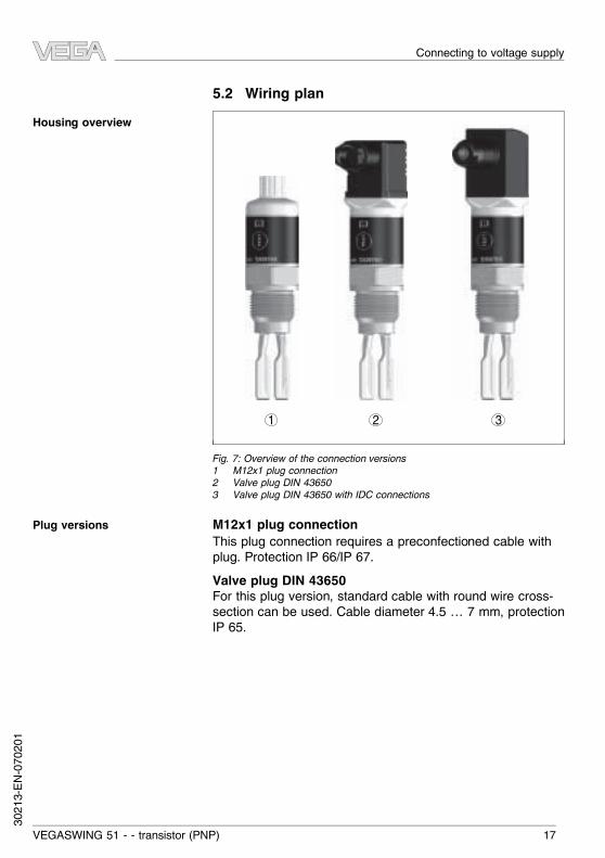
Fig. 7: Overview of the connection versions1 M12x1 plug connection2 Valve plug DIN 436503 Valve plug DIN 43650 with IDC connections
M12x1 plug connectionThis plug connection requires a preconfectioned cable withplug. Protection IP 66/IP 67.Valve plug DIN 43650For this plug version, standard cable with round wire cross-section can be used. Cable diameter 4.5 … 7 mm, protectionIP 65.
Housing overview
Plug versions
VEGASWING 51 - - transistor (PNP) 17
Connecting to voltage supply
3021
3-EN-
0702
01
1
45
6
7
8
910
2 3
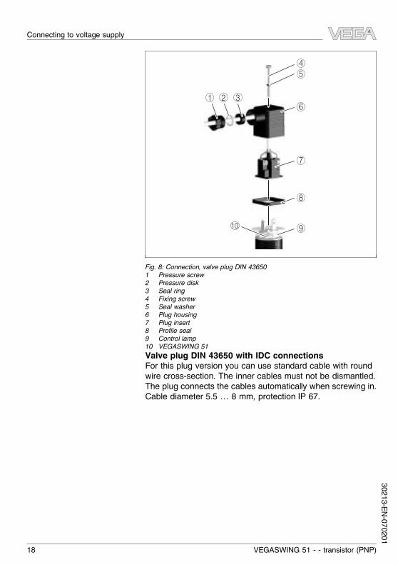
Fig. 8: Connection, valve plug DIN 436501 Pressure screw2 Pressure disk3 Seal ring4 Fixing screw5 Seal washer6 Plug housing7 Plug insert8 Profile seal9 Control lamp10 VEGASWING 51Valve plug DIN 43650 with IDC connectionsFor this plug version you can use standard cable with roundwire cross-section. The inner cables must not be dismantled.The plug connects the cables automatically when screwing in.Cable diameter 5.5 … 8 mm, protection IP 67.
18 VEGASWING 51 - - transistor (PNP)
Connecting to voltage supply
30213-EN-070201
1 2 3
4
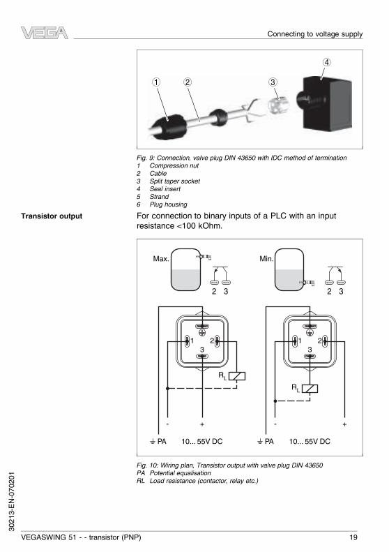
Fig. 9: Connection, valve plug DIN 43650 with IDC method of termination1 Compression nut2 Cable3 Split taper socket4 Seal insert5 Strand6 Plug housingFor connection to binary inputs of a PLC with an inputresistance <100 kOhm.
2 3 2 3
Max. Min.
321
321
- +
10... 55V DC 10... 55V DC
RLRL
- +
PA PA
Fig. 10: Wiring plan, Transistor output with valve plug DIN 43650PA Potential equalisationRL Load resistance (contactor, relay etc.)
Transistor output
VEGASWING 51 - - transistor (PNP) 19
Connecting to voltage supply
3021
3-EN-
0702
01
1 2 1 4
10... 55V DC 10... 55V DC
RLRL
1
4
2
3
1
4
2
3
-
Max. Min.
-+ +
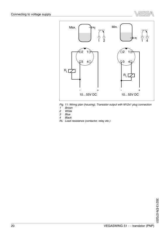
Fig. 11: Wiring plan (housing), Transistor output with M12x1 plug connection1 Brown2 White3 Blue4 BlackRL Load resistance (contactor, relay etc.)
20 VEGASWING 51 - - transistor (PNP)
Connecting to voltage supply
30213-EN-070201
6 Setup6.1 Indication of the switching statusThe switching status of the electronics can be checked on theupper part of the housing.
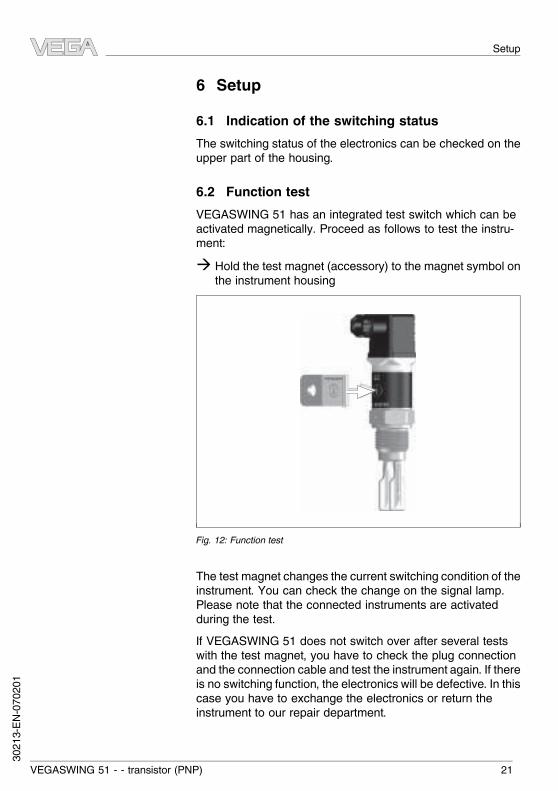
6.2 Function testVEGASWING 51 has an integrated test switch which can beactivated magnetically. Proceed as follows to test the instru-ment:à Hold the test magnet (accessory) to the magnet symbol on
the instrument housing
Fig. 12: Function test
The test magnet changes the current switching condition of theinstrument. You can check the change on the signal lamp.Please note that the connected instruments are activatedduring the test.If VEGASWING 51 does not switch over after several testswith the test magnet, you have to check the plug connectionand the connection cable and test the instrument again. If thereis no switching function, the electronics will be defective. In thiscase you have to exchange the electronics or return theinstrument to our repair department.
VEGASWING 51 - - transistor (PNP) 21
Setup
3021
3-EN-
0702
01
Caution:It is absolutely necessary that you remove the test magnetafter the test from the instrument housing.
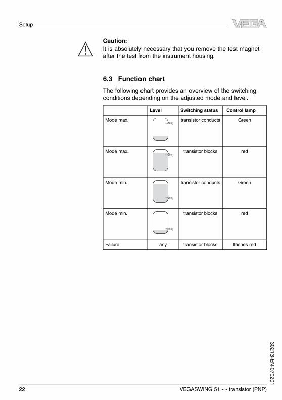
6.3 Function chartThe following chart provides an overview of the switchingconditions depending on the adjusted mode and level.
Level Switching status Control lampMode max. transistor conducts Green
Mode max. transistor blocks red
Mode min. transistor conducts Green
Mode min. transistor blocks red
Failure any transistor blocks flashes red
22 VEGASWING 51 - - transistor (PNP)
Setup
30213-EN-070201
7 Maintenance and fault rectification7.1 MaintenanceWhen used as directed in normal operation, VEGASWING 51is completely maintenance free.
7.2 Remove interferencesVEGASWING 51 offers maximum reliability. Neverthelessfaults can occur during operation. These may be caused by thefollowing, e.g.:l Sensorl Processl Supplyl Signal processingThe first measure to be taken is to check the output signal. Inmany cases, the causes can be determined this way and thefaults rectified.However, should this measures not be successful, call theVEGA service hotline in urgent cases under the phone no. +491805 858550.The hotline is available to you 7 days a week round-the-clock.Since we offer this service world-wide, the support is onlyavailable in the English language. The service is free ofcharge, only the standard telephone costs will be charged.? Control lamps off
l Voltage supply interrupted.à Check the voltage supply and the cable connectionà Exchange the electronics module
? Signal lamp flashes redl There was no load connected when connecting to
power supplyà Connect the instrument correctlyà Check if the tuning fork is damage or extremely
corrodedl Frequency errorà Adjust the instrument correctly
Causes of malfunction
Fault clearance
24 hour service hotline
Checking the switching signal
VEGASWING 51 - - transistor (PNP) 23
Maintenance and fault rectification
3021
3-EN-
0702
01
? The signal lamp flashes alternately red and greenl Shortcircuit or overloadà Check the electrical connection
7.3 Exchange of the electronicsTo exchange the electronics in case of failure, it is notnecessary to dismount the instrument.Dismounting the electronics module can destroy the housingseal. Therefore only open the instrument if you want to insert anew electronics module. The housing seal is supplied with theelectronics module.You require an electronics module type SWE50T or SWE50C.If you want to use an electronics module with a different signaloutput (e.g. contactless electronic switch SWE50C), you candownload the suitable operating instructions manual from ourhomepage under Downloads. Take note of the specificationsin the respective operating instructions manual.To exchange the electronics module, proceed as follows:1 Separate VEGASWING 51 from operating voltage2 Loosen screw (1) of the valve plug (2) with a wrench
(loosenM12x1 plug connection by turning the compressionnut)
3 Remove valve plug (2) or M12x1 according to drawing4 Remove lateral fixing screw (7) with a crosstip screwdriver5 Pull electronics module (4) carefully out of the housing (8)6 Remove the plug of the connection cable (6) from the
socket on the oscillator (4)7 Set the 16-step rotating switch (5) of the new replacement
electronics module (4) to the value of the defectiveelectronics module
8 Insert the connection cable (6) in the socket of the newelectronics module (4)
9 Insert electronics module (4) into the housing (8). Makesure that the lateral thread on the electronics module isabove the hole on the housing (8)
10 Push the electronics module (4) flush into the housing (8)11 Screw in the lateral fixing screw (7) with a crosstip
screwdriver
24 VEGASWING 51 - - transistor (PNP)
Maintenance and fault rectification
30213-EN-070201
12 Plug the valve plug (2) to the instrument, make sure thatthe profile seal (3) is placed correctly
13 Tighten the screw (1) with a wrench (fasten M12x1 plugconnection by screwing the compression nut)
VEGASWING 51 is again ready for operation.
VEGASWING 51 - - transistor (PNP) 25
Maintenance and fault rectification
3021
3-EN-
0702
01
4
1
2
3
56
7
8
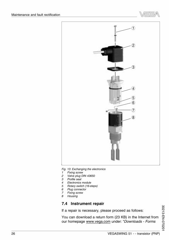
Fig. 13: Exchanging the electronics1 Fixing screw2 Valve plug DIN 436503 Profile seal4 Electronics module5 Rotary switch (16-steps)6 Plug connector7 Fixing screw8 Housing
7.4 Instrument repairIf a repair is necessary, please proceed as follows:You can download a return form (23 KB) in the Internet fromour homepage www.vega.com under: "Downloads - Forms
26 VEGASWING 51 - - transistor (PNP)
Maintenance and fault rectification
30213-EN-070201
and Certificates - Repair form".By doing this you help us carry out the repair quickly andwithout having to call for needed information.l Print and fill out one form per instrumentl Clean the instrument and pack it damage-proofl Attach the filled in form and if necessary, a safety data
sheet to the instrumentl Please ask the agency serving you for the address of your
return shipment. You find the respective agency on ourwebsite www.vega.com under: "Company - VEGA world-wide"
VEGASWING 51 - - transistor (PNP) 27
Maintenance and fault rectification
3021
3-EN-
0702
01
8 Dismounting8.1 Dismounting stepsWarning:Before dismounting, be aware of dangerous process con-ditions such as e.g. pressure in the vessel, high temperatures,corrosive or toxic products etc.
Take note of chapters "Mounting" and "Connecting to powersupply" and carry out the listed steps in reverse order.
8.2 DisposalThe instrument consists of materials which can be recycled byspecialised recycling companies. We use recyclable materialsand have designed the electronics to be easily separable.WEEE directive 2002/96/EGThis instrument is not subject to the WEEE directive 2002/96/EG and the respective national laws (in Germany, e.g.ElektroG). Pass the instrument directly on to a specialisedrecycling company and do not use the municipal collectingpoints. These may be used only for privately used productsaccording to the WEEE directive.Correct disposal avoids negative effects to persons andenvironment and ensures recycling of useful raw materials.Materials: see "Technical data"If you cannot dispose of the instrument properly, pleasecontact us about disposal methods or return.
Dismounting
28 VEGASWING 51 - - transistor (PNP)
30213-EN-070201
9 Supplement9.1 Technical dataGeneral dataMaterial 316L corresponds to 1.4404 or 1.4435Materials, wetted parts- Tuning fork 316L- Process seal Klingersil C-4400- Process fittings 316LMaterials, non-wetted parts- Housing 316L and plastic PEIWeight approx. 250 g (9 oz)Process fittings- Thread G¾ A, G1 A, ¾ NPT or 1 NPT- hygienic fittings Tri-Clamp 1", Tri-Clamp 1½", bolting DN 25
PN 40, bolting DN 40 PN 40, SMSSurface quality- Standard Ra <3.2 µm (1.26-4 in)- hygienic version Ra <0.8 µm (3.15-5 in)
Measuring accuracyHysteresis approx. 2 mm (0.08 in) with vertical installationIntegration time approx. 500 msFrequency approx. 1200 Hz
Ambient conditionsAmbient temperature on the housing -40 … +70 °C (-40 … +158 °F)Storage and transport temperature -40 … +80 °C (-40 … +176 °F)
Process conditionsProcess pressure -1 … 64 bar (-14.5 … 938 psi)Process temperature - Standard -40 … +100 °C (-40 … +212 °F)
Supplement
VEGASWING 51 - - transistor (PNP) 29
3021
3-EN-
0702
01
1
2
0�°C(32�°F)
-20�°C(-4�°F)
40�°C(104�°F)
20�°C(68�°F)
80�°C(176�°F)
60�°C(140�°F)
-40�°C(-40�°F)
0�°C(32�°F)
70�°C(158�°F)
50�°C(122�°F)
-40�°C(-40�°F) 100�°C
(212�°F)
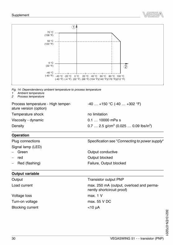
Fig. 14: Dependendency ambient temperature to process temperature1 Ambient temperature2 Process temperature
Process temperature - High temper-ature version (option)
-40 … +150 °C (-40 … +302 °F)
Temperature shock no limitationViscosity - dynamic 0.1 … 10000 mPa sDensity 0.7 … 2.5 g/cm³ (0.025 … 0.09 lbs/in³)
OperationPlug connections Specification see "Connecting to power supply"Signal lamp (LED)- Green Output conductive- red Output blocked- Red (flashing) Failure, Output blocked
Output variableOutput Transistor output PNPLoad current max. 250 mA (output, overload and perma-
nently shortcircuit proof)Voltage loss max. 1 VTurn-on voltage max. 55 V DCBlocking current <10 µA
Supplement
30 VEGASWING 51 - - transistor (PNP)
30213-EN-070201
Mode- Min./Max. Changeover by electronic connection- Max. Overfill protection- Min. Dry run protection
Voltage supplySupply voltage 10 … 55 V DCPower consumption max. 0.5 W
Electromechanical dataValve plug DIN 43650- Wire cross-section 1.5 mm² (0.06 in²)- Cable outer diameter 4.5 … 7 mm (0.18 … 0.28 in)Valve plug DIN 43650 with IDC connections- Wire cross-section for wire cross-section of 0.5 … 1 mm²
(0.02 … 0.04 in²)- Single wire diameter >0.1 mm (0.004 in)- Wire diameter 1.6 … 2 mm² (0.06 … 0.08 in²)- Cable outer diameter 5.5 … 8 mm (0.22 … 0.31 in)- Connection frequency 10x (on the same cross-section)
Electrical protective measuresProtection- Valve plug DIN 43650 IP 65- Valve plug DIN 43650 with IDC
connectionsIP 67
- M12x1 plug connection IP 66/IP 67Overvoltage category IIIProtection class II
ApprovalsOverfill protection according to WHGShip approvals
Supplement
VEGASWING 51 - - transistor (PNP) 31
3021
3-EN-
0702
01
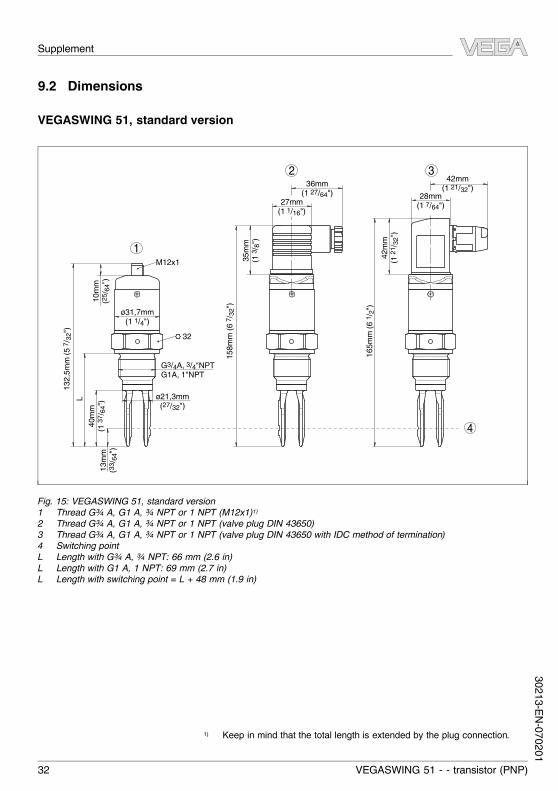
9.2 Dimensions
VEGASWING 51, standard version
158m
m (6
7 /32
")
165m
m (6
1 /2"
)
35m
m(1
3 /8"
)
42m
m(1
21/ 3
2")
27mm(1 1/16")
36mm(1 27/64") 28mm
(1 7/64")
L40
mm
(1 37
/ 64"
)10
mm
(25 /
64")
13m
m(3
3 /64
")
ø21,3mm(27/32")
ø31,7mm(1 1/4")
G3/4A, 3/4"NPTG1A, 1"NPT
32
1
4
2 3
132,
5mm
(5 7 /
32")
42mm(1 21/32")
M12x1
Fig. 15: VEGASWING 51, standard version1 Thread G¾ A, G1 A, ¾ NPT or 1 NPT (M12x1)1)2 Thread G¾ A, G1 A, ¾ NPT or 1 NPT (valve plug DIN 43650)3 Thread G¾ A, G1 A, ¾ NPT or 1 NPT (valve plug DIN 43650 with IDC method of termination)4 Switching pointL Length with G¾ A, ¾ NPT: 66 mm (2.6 in)L Length with G1 A, 1 NPT: 69 mm (2.7 in)L Length with switching point = L + 48 mm (1.9 in)
1) Keep in mind that the total length is extended by the plug connection.
Supplement
32 VEGASWING 51 - - transistor (PNP)
30213-EN-070201
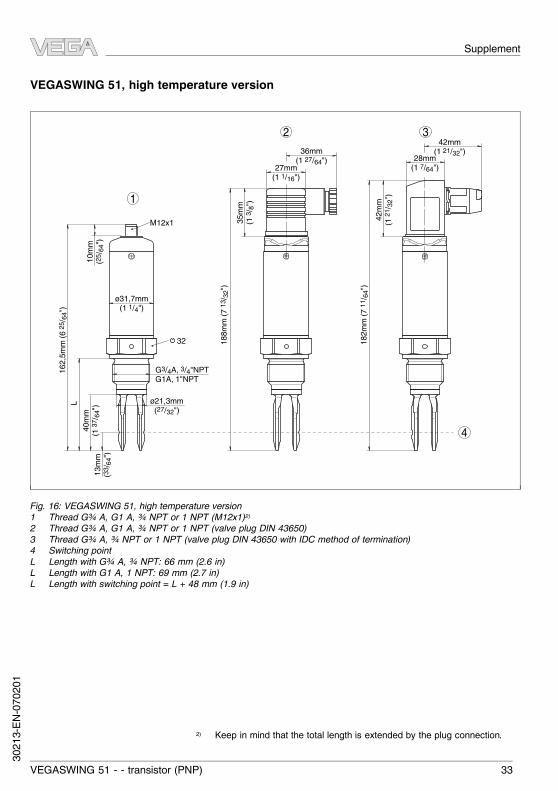
VEGASWING 51, high temperature version16
2,5m
m (6
25/ 6
4")
188m
m (7
13/ 3
2")
182m
m (7
11/ 6
4")
35m
m(1
3 /8"
)
27mm(1 1/16")
36mm(1 27/64")
L40
mm
(1 37
/ 64"
)13
mm
(33 /
64")
ø21,3mm(27/32")
ø31,7mm(1 1/4")
G3/4A, 3/4"NPTG1A, 1"NPT
32
1
4
2 3
42m
m(1
21/ 3
2")
28mm(1 7/64")
42mm(1 21/32")
10m
m(2
5 /64
")
M12x1
Fig. 16: VEGASWING 51, high temperature version1 Thread G¾ A, G1 A, ¾ NPT or 1 NPT (M12x1)2)2 Thread G¾ A, G1 A, ¾ NPT or 1 NPT (valve plug DIN 43650)3 Thread G¾ A, ¾ NPT or 1 NPT (valve plug DIN 43650 with IDC method of termination)4 Switching pointL Length with G¾ A, ¾ NPT: 66 mm (2.6 in)L Length with G1 A, 1 NPT: 69 mm (2.7 in)L Length with switching point = L + 48 mm (1.9 in)
2) Keep in mind that the total length is extended by the plug connection.
Supplement
VEGASWING 51 - - transistor (PNP) 33
3021
3-EN-
0702
01

VEGASWING 51, hygienic versions~1
01 m
m (3
31/ 3
2")
4
L
21 3
~115
mm
(7 13
/ 32"
)L
40 m
m(1
37/ 6
4")
~105
mm
(4 9 /
64")
L
13 m
m(3
3 /64
")
Fig. 17: VEGASWING 51, hygienic versions1 Tri-Clamp (valve plug DIN 43650)2 Bolting (valve plug DIN 43650)3 SMS 1145 (valve plug DIN 43650)4 Switching pointL Length with Tri-Clamp: 53 mm (2.1 in)L Length with bolting: 53 mm (2.1 in)L Length with SMS 1145: 53 mm (2.1 in)
Supplement
34 VEGASWING 51 - - transistor (PNP)
30213-EN-070201
9.3 Industrial property rightsVEGA product lines are global protected by industrial property rights.Further information see http://www.vega.com.Only in U.S.A.: Further information see patent label at the sensor housing.VEGA Produktfamilien sind weltweit geschützt durch gewerbliche Schutzrechte.Nähere Informationen unter http://www.vega.com.Les lignes de produits VEGA sont globalement protégées par des droits depropriété intellectuelle.Pour plus d'informations, on pourra se référer au site http://www.vega.com.VEGA lineas de productos están protegidas por los derechos en el campo de lapropiedad industrial.Para mayor información revise la pagina web http://www.vega.com.Линии продукции фирмы ВЕГА защищаются по всему миру правами наинтеллектуальную собственность.Дальнейшую информацию смотрите на сайте http://www.vega.com.德�VEGA公司列�品在全球享有知���保�。�一步信息���网站<http://www.vega.com>。
9.4 TrademarkAll brands used as well as trade and company names areproperty of their lawful proprietor/originator.
Supplement
VEGASWING 51 - - transistor (PNP) 35
3021
3-EN-
0702
01

VEGA Grieshaber KGAm Hohenstein 11377761 SchiltachGermanyPhone +49 7836 50-0Fax +49 7836 50-201E-mail: [email protected]
ISO 9001
All statements concerning scope of delivery, application,practical use and operating conditions of the sensors andprocessing systems correspond to the information avail-
able at the time of printing.© VEGA Grieshaber KG, Schiltach/Germany 2007
Subject to change without prior notice 30213-EN-070201