Embed Size (px)
Citation preview
Operating Instructions
VEGAMIP R61Receiving unit
Relay
Document ID: 35786

2
Contents
VEGAMIP R61 • Receiving unit
35786-EN-200522
Contents1 About this document ............................................................................................................... 4
1.1 Function ........................................................................................................................... 41.2 Target group ..................................................................................................................... 41.3 Symbols used................................................................................................................... 4
2 For your safety ......................................................................................................................... 52.1 Authorised personnel ....................................................................................................... 52.2 Appropriate use ................................................................................................................ 52.3 Warning about incorrect use ............................................................................................. 52.4 General safety instructions ............................................................................................... 52.5 EU conformity ................................................................................................................... 62.6 Radio license for Europe .................................................................................................. 62.7 Radio license for USA/Canada ......................................................................................... 62.8 Installation and operation in the USA and Canada ........................................................... 62.9 Environmental instructions ............................................................................................... 6
3 Product description ................................................................................................................. 83.1 Configuration .................................................................................................................... 83.2 Principle of operation........................................................................................................ 83.3 Packaging, transport and storage ................................................................................... 103.4 Accessories.................................................................................................................... 10
4 Mounting ................................................................................................................................. 124.1 General instructions ....................................................................................................... 124.2 Mounting instructions ..................................................................................................... 13
5 Connecting to power supply ................................................................................................. 245.1 Preparing the connection ............................................................................................... 245.2 Connection procedure .................................................................................................... 255.3 Wiring plan, single chamber housing.............................................................................. 26
6 Setup ....................................................................................................................................... 286.1 Adjustment system ......................................................................................................... 286.2 Adjustment ..................................................................................................................... 29
7 Maintenanceandfaultrectification ...................................................................................... 347.1 Maintenance .................................................................................................................. 347.2 Rectify faults ................................................................................................................... 347.3 Exchanging the electronics ............................................................................................ 357.4 How to proceed if a repair is necessary .......................................................................... 35
8 Dismount................................................................................................................................. 368.1 Dismounting steps.......................................................................................................... 368.2 Disposal ......................................................................................................................... 36
9 Supplement ............................................................................................................................ 379.1 Technical data ................................................................................................................ 379.2 Dimensions .................................................................................................................... 419.3 Industrial property rights ................................................................................................. 449.4 Trademark ...................................................................................................................... 44

3
Contents
VEGAMIP R61 • Receiving unit
3578
6-EN
-200
522
Safety instructions for Ex areasTakenoteoftheExspecificsafetyinstructionsforExapplications.These instructions are attached as documents to each instrument with Ex approval and are part of the operating instructions.
Editing status: 2020-05-20
4
1 About this document
VEGAMIP R61 • Receiving unit
35786-EN-200522
1 About this document
1.1 FunctionThis instruction provides all the information you need for mounting, connection and setup as well as important instructions for mainte-nance,faultrectification,theexchangeofpartsandthesafetyoftheuser. Please read this information before putting the instrument into operation and keep this manual accessible in the immediate vicinity of the device.
1.2 Target groupThis operating instructions manual is directed to trained personnel. Thecontentsofthismanualmustbemadeavailabletothequalifiedpersonnel and implemented.
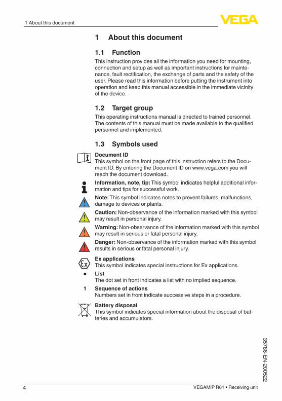
1.3 Symbols usedDocument IDThis symbol on the front page of this instruction refers to the Docu-ment ID. By entering the Document ID on www.vega.com you will reach the document download.Information, note, tip: This symbol indicates helpful additional infor-mation and tips for successful work.Note: This symbol indicates notes to prevent failures, malfunctions, damage to devices or plants.Caution: Non-observance of the information marked with this symbol may result in personal injury.Warning: Non-observance of the information marked with this symbol may result in serious or fatal personal injury.Danger: Non-observance of the information marked with this symbol results in serious or fatal personal injury.
Ex applicationsThis symbol indicates special instructions for Ex applications.
• ListThe dot set in front indicates a list with no implied sequence.
1 Sequence of actionsNumbers set in front indicate successive steps in a procedure.
Battery disposalThis symbol indicates special information about the disposal of bat-teries and accumulators.

5
2 For your safety
VEGAMIP R61 • Receiving unit
3578
6-EN
-200
522
2 For your safety
2.1 Authorised personnelAll operations described in this documentation must be carried out onlybytrained,qualifiedpersonnelauthorisedbytheplantoperator.During work on and with the device, the required personal protective equipment must always be worn.
2.2 Appropriate useThe VEGAMIP 61 is a sensor for point level detection.Youcanfinddetailedinformationabouttheareaofapplicationinchapter "Product description".Operational reliability is ensured only if the instrument is properly usedaccordingtothespecificationsintheoperatinginstructionsmanual as well as possible supplementary instructions.
2.3 Warning about incorrect useInappropriate or incorrect use of this product can give rise to applica-tion-specifichazards,e.g.vesseloverfillthroughincorrectmountingor adjustment. Damage to property and persons or environmental contamination can result. Also, the protective characteristics of the instrument can be impaired.
2.4 General safety instructionsThis is a state-of-the-art instrument complying with all prevailing regulations and directives. The instrument must only be operated in a technicallyflawlessandreliablecondition.Theoperatorisresponsi-ble for the trouble-free operation of the instrument. When measuring aggressive or corrosive media that can cause a dangerous situation if the instrument malfunctions, the operator has to implement suitable measures to make sure the instrument is functioning properly.The safety instructions in this operating instructions manual, the na-tional installation standards as well as the valid safety regulations and accident prevention rules must be observed by the user.For safety and warranty reasons, any invasive work on the device beyond that described in the operating instructions manual may be carried out only by personnel authorised by the manufacturer. Arbi-traryconversionsormodificationsareexplicitlyforbidden.Forsafetyreasons,onlytheaccessoryspecifiedbythemanufacturermustbeused.To avoid any danger, the safety approval markings and safety tips on the device must also be observed.The emitting frequencies of the sensors depend on the model, but are all in the K band range. The low transmitting power lies far below the internationally permitted limit value. When the instrument is used correctly, it presents no danger to human health. It may be operated without restriction outside of closed vessels.

6
2 For your safety
VEGAMIP R61 • Receiving unit
35786-EN-200522
2.5 EU conformityThedevicefulfilsthelegalrequirementsoftheapplicableEUdirec-tives.ByaffixingtheCEmarking,weconfirmtheconformityoftheinstrument with these directives.The EU conformity declaration can be found on our homepage.
Electromagnetic compatibilityInstruments in four-wire or Ex-d-ia version are designed for use in an industrial environment. Nevertheless, electromagnetic interference from electrical conductors and radiated emissions must be taken into account, as is usual with class A instruments according to EN 61326-1.Iftheinstrumentisusedinadifferentenvironment,theelectromag-netic compatibility to other instruments must be ensured by suitable measures.
2.6 Radio license for EuropeThe instrument was tested according to the latest issue of the follow-ingharmonizedstandards:EN 300440-1 - Short Range Devices (SRD)
2.7 Radio license for USA/CanadaOperationisonlypermittedifthefollowingtwoconditionsarefulfilled:
• The instrument must not emit interference radiation• Theinstrumentmustoperatewithoutbeingaffectedbyincoming
interference radiation, including such that may trigger unwanted operating conditions.
The instrument is in conformity with the following regulations:FCC: Part 15 of the FCC regulationsIC: RSS-210 Issue 7, RSS-GEN Issue 2 and RSS-102 Issue 4 of the IC regulations.Conversionsormodificationsoftheinstrumentnotexpresslyap-proved by the manufacturer will lead to loss of the approval.Before use, make sure that the respective approval numbers are stated on the type label (see chapter "Configuration").
2.8 Installation and operation in the USA and Canada
This information is only valid for USA and Canada. Hence the follow-ing text is only available in the English language.Installations in the US shall comply with the relevant requirements of the National Electrical Code (ANSI/NFPA 70).Installations in Canada shall comply with the relevant requirements of the Canadian Electrical Code.
2.9 Environmental instructionsProtection of the environment is one of our most important duties. That is why we have introduced an environment management system

7
2 For your safety
VEGAMIP R61 • Receiving unit
3578
6-EN
-200
522
with the goal of continuously improving company environmental pro-tection.Theenvironmentmanagementsystemiscertifiedaccordingto DIN EN ISO 14001.Pleasehelpusfulfilthisobligationbyobservingtheenvironmentalinstructions in this manual:
• Chapter "Packaging, transport and storage"• Chapter "Disposal"
8
3 Product description
VEGAMIP R61 • Receiving unit
35786-EN-200522
3 Product description
3.1 ConfigurationThetypelabelcontainsthemostimportantdataforidentificationanduse of the instrument:
• Article number• Serial number• Technical data• ID numbers, instrument documentation
The type label contains the serial number of the instrument. With it youcanfindthefollowinginstrumentdataonourhomepage:
• Product code (HTML)• Delivery date (HTML)• Order-specificinstrumentfeatures(HTML)• Operating instructions and quick setup guide at the time of ship-
ment (PDF)• Order-specificsensordataforanelectronicsexchange(XML)• Testcertificate(PDF)-optionalMove to "www.vega.com"andenterinthesearchfieldtheserialnumber of your instrument.Alternatively, you can access the data via your smartphone:
• Download the VEGA Tools app from the "Apple App Store" or the "Google Play Store"
• Scan the DataMatrix code on the type label of the instrument or• Enter the serial number manually in the app
The scope of delivery encompasses:
• Point level sensor VEGAMIP R61 (receiving unit)
The further scope of delivery encompasses:
• Documentation – Operating instructions VEGAMIP 61 – Instructions for optional instrument features – Ex-specific"Safety instructions" (with Ex versions) – Ifnecessary,furthercertificates
The corresponding emitting unit VEGAMIP T61 is described in a separate operating instructions manual.
3.2 Principle of operationVEGAMIP 61 is a microwave barrier for level detection.It is designed for industrial use in all areas of process technology and can be used in bulk solids and liquids.Typicalapplicationsareoverfillanddryrunprotection.Withanoperat-ing distance of 100 m, VEGAMIP 61 can be used, for example, in bulk solids silos with large diameters. Thanks to its simple and rugged measuringsystem,VEGAMIP61isvirtuallyunaffectedbytheprocessand the chemical and physical properties of the medium.
Type label
Serial number - Instru-ment search
Scope of delivery
Application area
9
3 Product description
VEGAMIP R61 • Receiving unit
3578
6-EN
-200
522
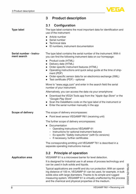
VEGAMIP 61 can also be used for detection of vehicles and ships or for material recognition on conveyor belts.Itworksevenunderextremelydifficultconditions:differentgrainsizes,contamination,extremefillingnoise,hightemperatures,strongdustgeneration and abrasive products are all no problem for the instru-ment.The VEGAMIP 61 consists of the components:
33
5
4
5
21
Fig. 1: VEGAMIP 61 with plastic housing1 Emitting unit VEGAMIP T612 Receiving unit VEGAMIP R61 with control electronics3 Housing lid4 Housing with control electronics5 Process fitting
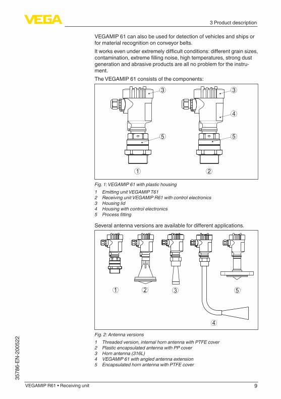
Severalantennaversionsareavailablefordifferentapplications.
1 2 3 5
4
Fig. 2: Antenna versions1 Threaded version, internal horn antenna with PTFE cover2 Plastic encapsulated antenna with PP cover3 Horn antenna (316L)4 VEGAMIP 61 with angled antenna extension5 Encapsulated horn antenna with PTFE cover
10
3 Product description
VEGAMIP R61 • Receiving unit
35786-EN-200522
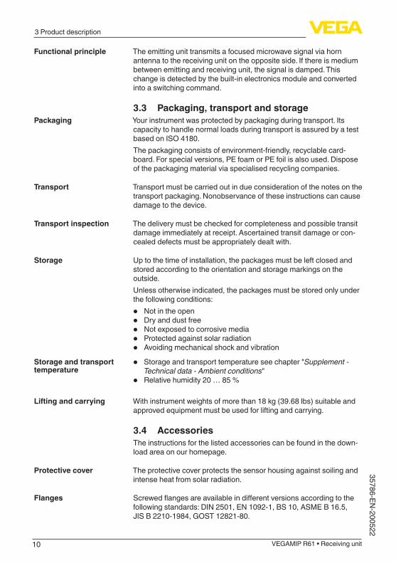
The emitting unit transmits a focused microwave signal via horn antenna to the receiving unit on the opposite side. If there is medium between emitting and receiving unit, the signal is damped. This change is detected by the built-in electronics module and converted into a switching command.
3.3 Packaging, transport and storageYour instrument was protected by packaging during transport. Its capacity to handle normal loads during transport is assured by a test based on ISO 4180.The packaging consists of environment-friendly, recyclable card-board. For special versions, PE foam or PE foil is also used. Dispose of the packaging material via specialised recycling companies.
Transport must be carried out in due consideration of the notes on the transport packaging. Nonobservance of these instructions can cause damage to the device.
The delivery must be checked for completeness and possible transit damage immediately at receipt. Ascertained transit damage or con-cealed defects must be appropriately dealt with.
Up to the time of installation, the packages must be left closed and stored according to the orientation and storage markings on the outside.Unless otherwise indicated, the packages must be stored only under the following conditions:
• Not in the open• Dry and dust free• Not exposed to corrosive media• Protected against solar radiation• Avoiding mechanical shock and vibration
• Storage and transport temperature see chapter "Supplement - Technical data - Ambient conditions"
• Relative humidity 20 … 85 %
With instrument weights of more than 18 kg (39.68 lbs) suitable and approved equipment must be used for lifting and carrying.
3.4 AccessoriesThe instructions for the listed accessories can be found in the down-load area on our homepage.
The protective cover protects the sensor housing against soiling and intense heat from solar radiation.
Screwedflangesareavailableindifferentversionsaccordingtothefollowing standards: DIN 2501, EN 1092-1, BS 10, ASME B 16.5, JIS B 2210-1984, GOST 12821-80.
Functional principle
Packaging
Transport
Transport inspection
Storage
Storage and transport temperature
Lifting and carrying
Protective cover
Flanges
11
3 Product description
VEGAMIP R61 • Receiving unit
3578
6-EN
-200
522
The pluggable display module PLICSLED is used for clearly visible indication of the switching status. It can be attached to the electronics of the sensor and removed at any time.
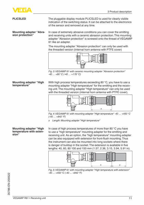
In case of extremely abrasive conditions you can cover the emitting and receiving units with a ceramic abrasion protection. This mounting adapter "Abrasion protection" is screwed onto the thread of VEGAMIP 61 like an adapter.The mounting adapter "Abrasion protection" can only be used with the threaded version (internal horn antenna with PTFE cover)
Fig. 3: VEGAMIP 61 with ceramic mounting adapter "Abrasion protection" -40 … +80 °C (-40 … +176 °C)
With high process temperatures exceeding 80 °C, you have to use a mounting adapter "High temperature" for the emitting and the receiv-ing unit. The mounting adapter "High temperature" can only be used with the threaded version (internal horn antenna with PTFE cover).
x
Fig. 4: VEGAMIP 61 with mounting adapter "High temperature" -40 … +450 °C (-40 … +842 °F)x Length: Mounting adapter "High temperature"
In case of high process temperatures of more than 80 °C you have to use a "high temperature" mounting adapter for the emitting and receiving unit. As an option, the "high temperature" mounting adapter canbealsoequippedwithextensionforfront-flushmounting.Thusthe instrument can also be mounted into long sockets where there isdangerofbuildupinthesocket.Theextensionisavailableinfivelengths: 40, 60, 80 100 and 150 mm (1.57, 2.36, 3.15, 3.94, 5.91 in).
x y
Fig. 5: VEGAMIP 61 with mounting adapter "High temperature with extension" -40 … +450 °C (-40 … +842 °F)
PLICSLED
Mounting adapter "Abra-sion protection"
Mounting adapter "High temperature"
Mounting adapter "High temperature with exten-sion"
12
4 Mounting
VEGAMIP R61 • Receiving unit
35786-EN-200522
4 Mounting
4.1 General instructionsDeviceswiththreadedfittingarescrewedintotheprocessfittingwitha suitable wrench via the hexagon.See chapter "Dimensions"forwrenchsize.
Warning:The housing or the electrical connection may not be used for screw-ing in! Depending on the device version, tightening can cause dam-age, e. g. to the rotation mechanism of the housing.
Note:For safety reasons, the instrument must only be operated within the permissibleprocessconditions.Youcanfinddetailedinformationonthe process conditions in chapter "Technical data" of the operating instructions or on the type label.
Hence make sure before mounting that all parts of the instrument ex-posed to the process are suitable for the existing process conditions.These are mainly:
• Active measuring component• Processfitting• Process seal
Process conditions in particular are:
• Process pressure• Process temperature• Chemical properties of the medium• Abrasionandmechanicalinfluences
Protect your instrument against moisture ingress through the following measures:
• Use a suitable connection cable (see chapter "Connecting to power supply")
• Tighten the cable gland or plug connector• Lead the connection cable downward in front of the cable entry or
plug connector
This applies mainly to outdoor installations, in areas where high humidity is expected (e.g. through cleaning processes) and on cooled or heated vessels.
Note:Makesurethatthedegreeofcontaminationspecifiedinchapter"Technical data" meets the existing ambient conditions.
Note:Make sure that during installation or maintenance no moisture or dirt can get inside the instrument.To maintain the housing protection, make sure that the housing lid is closed during operation and locked, if necessary.
Screwing in
Process conditions
Protection against mois-ture
13
4 Mounting
VEGAMIP R61 • Receiving unit
3578
6-EN
-200
522
Metric threadsIn the case of instrument housings with metric thread, the cable glands are screwed in at the factory. They are sealed with plastic plugs as transport protection.You have to remove these plugs before electrical connection.
NPT threadIn the case of instrument housings with self-sealing NPT threads, it is not possible to have the cable entries screwed in at the factory. The free openings for the cable glands are therefore covered with red dust protection caps as transport protection. The dust protection caps do notprovidesufficientprotectionagainstmoisture.Prior to setup you have to replace these protective caps with ap-proved cable glands or close the openings with suitable blind plugs.
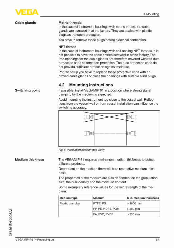
4.2 Mounting instructionsIf possible, install VEGAMIP 61 in a position where strong signal damping by the medium is expected.Avoidmountingtheinstrumenttooclosetothevesselwall.Reflec-tionsfromthevesselwallorfromvesselinstallationcaninfluencetheswitching accuracy.
Fig. 6: Installation position (top view)
The VEGAMIP 61 requires a minimum medium thickness to detect differentproducts.Dependent on the medium there will be a respective medium thick-ness.The properties of the medium are also dependent on the granulation size,thebulkdensityandthemoisturecontent.Some exemplary reference values for the min. strength of the me-dium:
Medium type Medium Min. medium thickness
Plastic granules PTFE, PS > 1000 mm
PP, PE, HDPE, POM > 500 mm
PA, PVC, PVDF > 250 mm
Cable glands
Switching point
Medium thickness
14
4 Mounting
VEGAMIP R61 • Receiving unit
35786-EN-200522
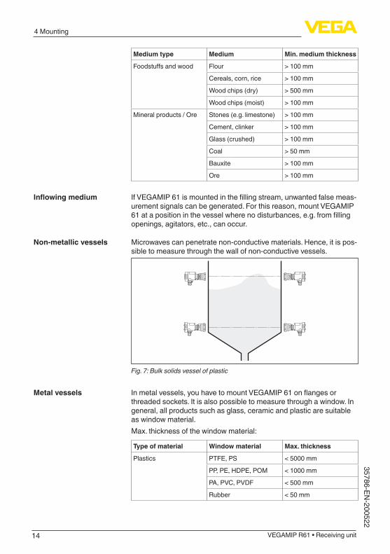
Medium type Medium Min. medium thickness
Foodstuffsandwood Flour > 100 mm
Cereals, corn, rice > 100 mm
Wood chips (dry) > 500 mm
Wood chips (moist) > 100 mm
Mineral products / Ore Stones (e.g. limestone) > 100 mm
Cement, clinker > 100 mm
Glass (crushed) > 100 mm
Coal > 50 mm
Bauxite > 100 mm
Ore > 100 mm
IfVEGAMIP61ismountedinthefillingstream,unwantedfalsemeas-urement signals can be generated. For this reason, mount VEGAMIP 61atapositioninthevesselwherenodisturbances,e.g.fromfillingopenings, agitators, etc., can occur.
Microwaves can penetrate non-conductive materials. Hence, it is pos-sible to measure through the wall of non-conductive vessels.
Fig. 7: Bulk solids vessel of plastic
Inmetalvessels,youhavetomountVEGAMIP61onflangesorthreaded sockets. It is also possible to measure through a window. In general, all products such as glass, ceramic and plastic are suitable as window material.Max. thickness of the window material:
Type of material Window material Max. thickness
Plastics PTFE, PS < 5000 mm
PP, PE, HDPE, POM < 1000 mm
PA, PVC, PVDF < 500 mm
Rubber < 50 mm
Inflowingmedium
Non-metallic vessels
Metal vessels
15
4 Mounting
VEGAMIP R61 • Receiving unit
3578
6-EN
-200
522
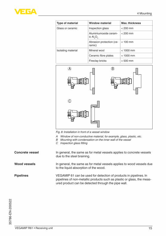
Type of material Window material Max. thickness
Glass or ceramic Inspection glass < 200 mm
Aluminiumoxide ceram-ic Al2O3
< 200 mm
Abrasion protection (ce-ramic)
< 100 mm
Isolating material Mineral wool < 1000 mm
Ceramicfibreplates < 1000 mm
Fireclay bricks < 500 mm
A
C
B
Fig. 8: Installation in front of a vessel windowA Window of non-conductive material, for example, glass, plastic, etc.B Mounting with condensation on the inner wall of the vesselC Inspection glass fitting
In general, the same as for metal vessels applies to concrete vessels due to the steel braining.
In general, the same as for metal vessels applies to wood vessels due to the liquid absorption of the wood.
VEGAMIP 61 can be used for detection of products in pipelines. In pipelines of non-metallic products such as plastic or glass, the meas-ured product can be detected through the pipe wall.
Concrete vessel
Wood vessels
Pipelines

16
4 Mounting
VEGAMIP R61 • Receiving unit
35786-EN-200522
x
Fig. 9: Installation in pipelinesx Min. distance 100 mm (3.94 in)
Mount the threaded version of VEGAMIP 61 in the following way:
1 2 3 4
Fig. 10: VEGAMIP 61, threaded version G1½1 Polarisation marking2 Instrument hexagon3 Counter nut4 Process seal
1. Insert the supplied process seal (4) before screwing in the instru-ment
2. To screw VEGAMIP 61 in, use the instrument hexagon (2) below the housing.Screwtheinstrumentinandtightenitlightlywithaflatspanner
3. Turn the sensor back (max. 180°) to reach the required orientation of the polarisation marking (1)
4. Hold the instrument in this position and tighten with the counter nut (3)
Caution:The housing must not be used to screw the instrument in! Applying tightening force can damage internal parts of the housing.
Note:In the case of VEGAMIP 61 with NPT thread, the instrument seals in the thread itself. Hence, no counter nut is necessary for these ver-sions.
Threaded version
17
4 Mounting
VEGAMIP R61 • Receiving unit
3578
6-EN
-200
522
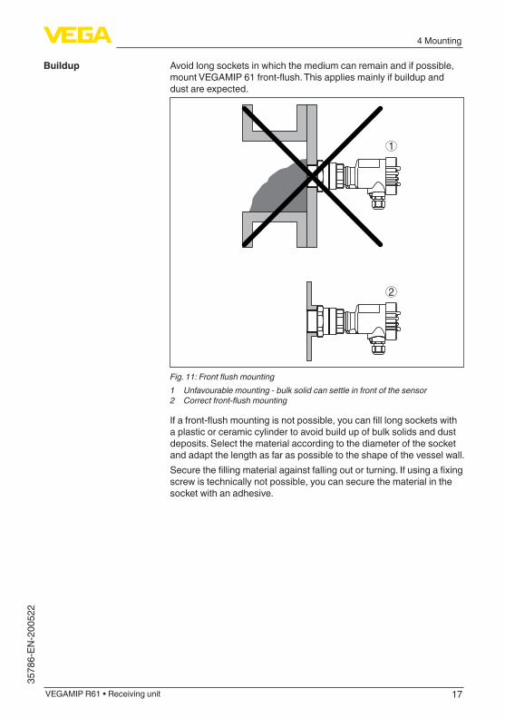
Avoid long sockets in which the medium can remain and if possible, mountVEGAMIP61front-flush.Thisappliesmainlyifbuildupanddust are expected.
2
1
Fig. 11: Front flush mounting1 Unfavourable mounting - bulk solid can settle in front of the sensor2 Correct front-flush mounting
Ifafront-flushmountingisnotpossible,youcanfilllongsocketswitha plastic or ceramic cylinder to avoid build up of bulk solids and dust deposits. Select the material according to the diameter of the socket and adapt the length as far as possible to the shape of the vessel wall.Securethefillingmaterialagainstfallingoutorturning.Ifusingafixingscrew is technically not possible, you can secure the material in the socket with an adhesive.
Buildup
18
4 Mounting
VEGAMIP R61 • Receiving unit
35786-EN-200522
2
1
2
21
1
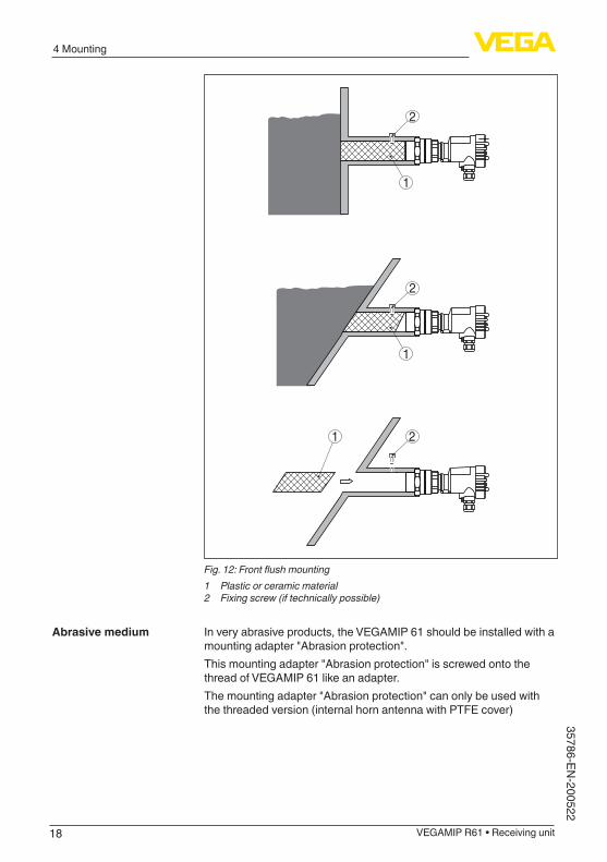
Fig. 12: Front flush mounting1 Plastic or ceramic material2 Fixing screw (if technically possible)
In very abrasive products, the VEGAMIP 61 should be installed with a mounting adapter "Abrasion protection".This mounting adapter "Abrasion protection" is screwed onto the thread of VEGAMIP 61 like an adapter.The mounting adapter "Abrasion protection" can only be used with the threaded version (internal horn antenna with PTFE cover)
Abrasive medium
19
4 Mounting
VEGAMIP R61 • Receiving unit
3578
6-EN
-200
522
Fig. 13: VEGAMIP 61 with ceramic mounting adapter "Abrasion protection" -40 … +80 °C (-40 … +176 °C)
As an alternative you can install the VEGAMIP 61 in front of a suitable window. In such case, use a respectively resistant window material.
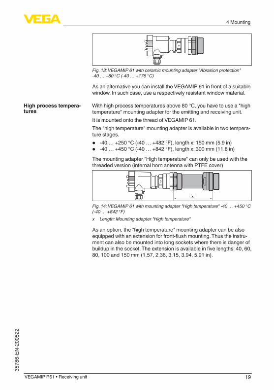
With high process temperatures above 80 °C, you have to use a "high temperature" mounting adapter for the emitting and receiving unit.It is mounted onto the thread of VEGAMIP 61.The "high temperature" mounting adapter is available in two tempera-ture stages.
• -40 … +250 °C (-40 … +482 °F), length x: 150 mm (5.9 in)• -40 … +450 °C (-40 … +842 °F), length x: 300 mm (11.8 in)
The mounting adapter "High temperature" can only be used with the threaded version (internal horn antenna with PTFE cover)
x
Fig. 14: VEGAMIP 61 with mounting adapter "High temperature" -40 … +450 °C (-40 … +842 °F)x Length: Mounting adapter "High temperature"
As an option, the "high temperature" mounting adapter can be also equippedwithanextensionforfront-flushmounting.Thustheinstru-ment can also be mounted into long sockets where there is danger of buildupinthesocket.Theextensionisavailableinfivelengths:40,60,80, 100 and 150 mm (1.57, 2.36, 3.15, 3.94, 5.91 in).
High process tempera-tures
20
4 Mounting
VEGAMIP R61 • Receiving unit
35786-EN-200522
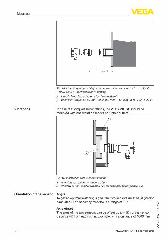
yx
Fig. 15: Mounting adapter "High temperature with extension" -40 … +450 °C (-40 … +842 °F) for front-flush mountingx Length: Mounting adapter "High temperature"y Extension length 40, 60, 80, 100 or 150 mm (1.57, 2.36, 3.15, 3.94, 5.91 in)
In case of strong vessel vibrations, the VEGAMIP 61 should be mountedwithantivibrationblocksorrubberbuffers.
1
2
Fig. 16: Installation with vessel vibrations1 Anti vibration blocks or rubber buffers2 Window of non-conductive material, for example, glass, plastic, etc.
AngleTo get an optimal switching signal, the two sensors must be aligned to each other. The accuracy must be in a range of ±5°.
AxisoffsetTheaxesofthetwosensorscanbeoffsetupto<5%ofthesensordistance (d) from each other. Example: with a distance of 1000 mm
Vibrations
Orientation of the sensor
21
4 Mounting
VEGAMIP R61 • Receiving unit
3578
6-EN
-200
522
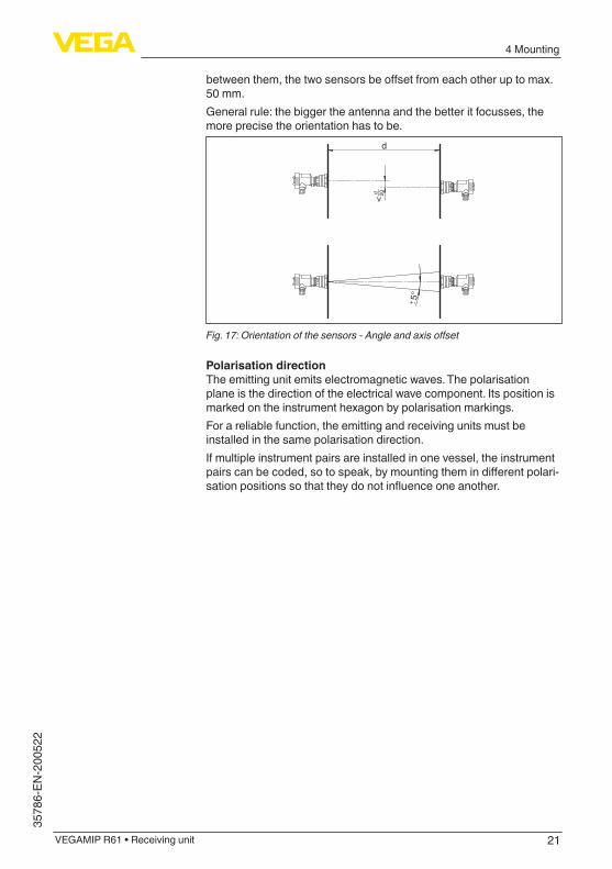
betweenthem,thetwosensorsbeoffsetfromeachotheruptomax.50 mm.General rule: the bigger the antenna and the better it focusses, the more precise the orientation has to be.
5°+ -
d
<d 20
Fig. 17: Orientation of the sensors - Angle and axis offset
Polarisation directionThe emitting unit emits electromagnetic waves. The polarisation plane is the direction of the electrical wave component. Its position is marked on the instrument hexagon by polarisation markings.For a reliable function, the emitting and receiving units must be installed in the same polarisation direction.If multiple instrument pairs are installed in one vessel, the instrument pairscanbecoded,sotospeak,bymountingthemindifferentpolari-sationpositionssothattheydonotinfluenceoneanother.
22
4 Mounting
VEGAMIP R61 • Receiving unit
35786-EN-200522
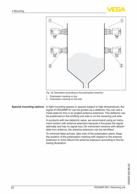
2
1 1
2
Fig. 18: Orientation according to the polarisation direction1 Polarisation marking on top2 Polarisation marking on the side
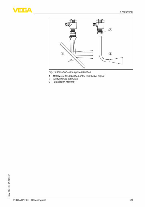
In tight mounting spaces or spaces subject to high temperatures, the signalofVEGAMIP61canbeguidedviaadeflector.Youcanuseametalplateforthisoranangledantennaextension.Thisdeflectorcanbe positioned on the emitting unit side or on the receiving unit side.In products with low dielectric value, we recommend using an instru-ment version with antenna extension because it focusses the signal optimally and has no signal loss. On instrument versions with detach-ablehornantenna,theantennaextensioncanberetrofitted.Tominimizefalseechoes,takenoteofthepolarisationplane.Keepthe position of the polarisation marking with respect to the antenna extension in mind. Mount the antenna extension according to the fol-lowing illustration.
Special mounting options
23
4 Mounting
VEGAMIP R61 • Receiving unit
3578
6-EN
-200
522
3
45°
1 2
Fig. 19: Possibilities for signal deflection1 Metal plate for deflection of the microwave signal2 Bent antenna extension3 Polarisation marking
24
5 Connecting to power supply
VEGAMIP R61 • Receiving unit
35786-EN-200522
5 Connecting to power supply
5.1 Preparing the connectionAlways keep in mind the following safety instructions:
• Carryoutelectricalconnectionbytrained,qualifiedpersonnelauthorised by the plant operator
• If overvoltage surges are expected, overvoltage arresters should be installed
Warning:Onlyconnectordisconnectinde-energizedstate.
Connect the operating voltage according to the connection diagrams. The electronics module is designed in protection class I. To maintain this protection class, it is absolutely necessary that the earth conduc-tor be connected to the inner earth conductor terminal. Keep the general installation regulations in mind. Take note of the correspond-inginstallationregulationsforhazardousareaswithExapplications.Thedataforpowersupplyarespecifiedinchapter"Technical data".
The instrument is connected with standard three-wire cable without shielding. If electromagnetic interference is expected which is above the test values of EN 61326 for industrial areas, shielded cable should be used.Make sure that the cable used has the required temperature resist-anceandfiresafetyformax.occurringambienttemperatureUse cable with round cross section for instruments with housing and cablegland.Toensurethesealeffectofthecablegland(IPprotectionrating),findoutwhichcableouterdiameterthecableglandissuitablefor.Useacableglandfittingthecablediameter.Cover all housing openings conforming to standard according to EN 60079-1.
Metric threadsIn the case of instrument housings with metric thread, the cable glands are screwed in at the factory. They are sealed with plastic plugs as transport protection.
Note:You have to remove these plugs before electrical connection.
NPT threadIn the case of instrument housings with self-sealing NPT threads, it is not possible to have the cable entries screwed in at the factory. The free openings for the cable glands are therefore covered with red dust protection caps as transport protection.
Note:Prior to setup you have to replace these protective caps with ap-proved cable glands or close the openings with suitable blind plugs.
Safety instructions
Voltage supply
Connection cable
Cable glands
25
5 Connecting to power supply
VEGAMIP R61 • Receiving unit
3578
6-EN
-200
522
On plastic housings, the NPT cable gland or the Conduit steel tube must be screwed into the threaded insert without grease.Max. torque for all housings, see chapter "Technical data".
5.2 Connection procedureThe voltage supply and signal output are connected via the spring-loaded terminals in the housing.
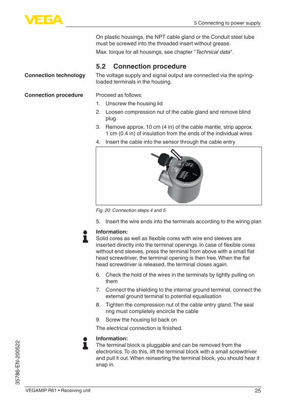
Proceed as follows:1. Unscrew the housing lid2. Loosen compression nut of the cable gland and remove blind
plug3. Remove approx. 10 cm (4 in) of the cable mantle, strip approx.
1 cm (0.4 in) of insulation from the ends of the individual wires4. Insert the cable into the sensor through the cable entry
Fig. 20: Connection steps 4 and 5
5. Insert the wire ends into the terminals according to the wiring plan
Information:Solidcoresaswellasflexiblecoreswithwireendsleevesareinserteddirectlyintotheterminalopenings.Incaseofflexiblecoreswithoutendsleeves,presstheterminalfromabovewithasmallflatheadscrewdriver,theterminalopeningisthenfree.Whentheflathead screwdriver is released, the terminal closes again.
6. Check the hold of the wires in the terminals by lightly pulling on them
7. Connect the shielding to the internal ground terminal, connect the external ground terminal to potential equalisation
8. Tighten the compression nut of the cable entry gland. The seal ring must completely encircle the cable
9. Screw the housing lid back onTheelectricalconnectionisfinished.
Information:The terminal block is pluggable and can be removed from the electronics. To do this, lift the terminal block with a small screwdriver and pull it out. When reinserting the terminal block, you should hear it snap in.
Connection technology
Connection procedure
26
5 Connecting to power supply
VEGAMIP R61 • Receiving unit
35786-EN-200522
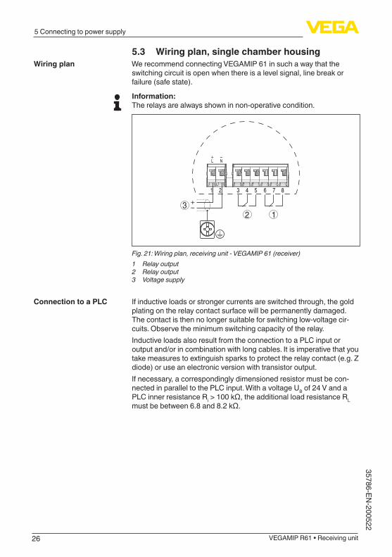
5.3 Wiring plan, single chamber housingWe recommend connecting VEGAMIP 61 in such a way that the switching circuit is open when there is a level signal, line break or failure (safe state).
Information:The relays are always shown in non-operative condition.
32 1
Fig. 21: Wiring plan, receiving unit - VEGAMIP 61 (receiver)1 Relay output2 Relay output3 Voltage supply
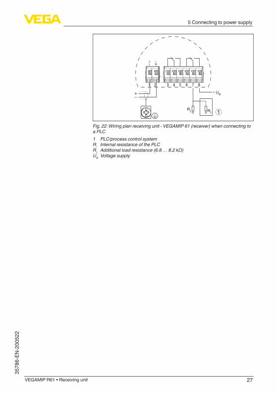
If inductive loads or stronger currents are switched through, the gold plating on the relay contact surface will be permanently damaged. The contact is then no longer suitable for switching low-voltage cir-cuits. Observe the minimum switching capacity of the relay.Inductive loads also result from the connection to a PLC input or output and/or in combination with long cables. It is imperative that you take measures to extinguish sparks to protect the relay contact (e.g. Z diode) or use an electronic version with transistor output.If necessary, a correspondingly dimensioned resistor must be con-nected in parallel to the PLC input. With a voltage UB of 24 V and a PLC inner resistance Ri>100kΩ,theadditionalloadresistanceRL mustbebetween6.8and8.2kΩ.
Wiring plan
Connection to a PLC
27
5 Connecting to power supply
VEGAMIP R61 • Receiving unit
3578
6-EN
-200
522
1RL RI
UB
Fig. 22: Wiring plan receiving unit - VEGAMIP 61 (receiver) when connecting to a PLC1 PLC/process control systemRi Internal resistance of the PLCRL Additional load resistance (6.8 … 8.2 kΩ)UB Voltage supply
28
6 Setup
VEGAMIP R61 • Receiving unit
35786-EN-200522
6 Setup
6.1 Adjustment system
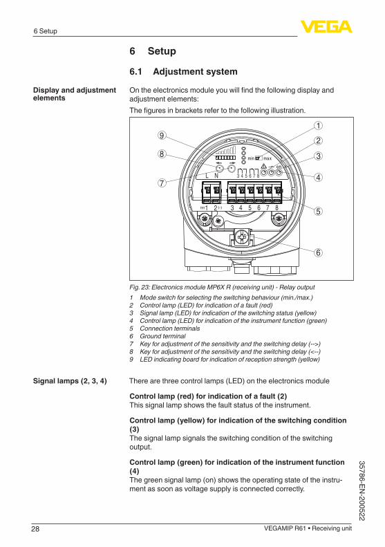
Ontheelectronicsmoduleyouwillfindthefollowingdisplayandadjustment elements:Thefiguresinbracketsrefertothefollowingillustration.
6
7
9
8
4
5
1
2
3
1
L N 3
(-)( )
4 5 6 7 8
2+ 3 4 5 6 7 8
Fig. 23: Electronics module MP6X R (receiving unit) - Relay output1 Mode switch for selecting the switching behaviour (min./max.)2 Control lamp (LED) for indication of a fault (red)3 Signal lamp (LED) for indication of the switching status (yellow)4 Control lamp (LED) for indication of the instrument function (green)5 Connection terminals6 Ground terminal7 Key for adjustment of the sensitivity and the switching delay (-->)8 Key for adjustment of the sensitivity and the switching delay (<--)9 LED indicating board for indication of reception strength (yellow)
There are three control lamps (LED) on the electronics module
Control lamp (red) for indication of a fault (2)This signal lamp shows the fault status of the instrument.
Control lamp (yellow) for indication of the switching condition (3)The signal lamp signals the switching condition of the switching output.
Control lamp (green) for indication of the instrument function (4)The green signal lamp (on) shows the operating state of the instru-ment as soon as voltage supply is connected correctly.
Display and adjustment elements
Signal lamps (2, 3, 4)
29
6 Setup
VEGAMIP R61 • Receiving unit
3578
6-EN
-200
522
With the mode switch (max./min.) you can change the switching status of the relay. You can set the required mode according to the "Function table"(max.-maximumdetectionoroverflowprotection,min. - minimum detection or dry run protection).
With these keys (7 and 8) you can adjust the switching point to the medium.Depending on the process, the sensitivity of VEGAMIP 61 must be set higher or lower.Pressing the "<--" key makes the sensor more sensitive. Pressing the "-->" key makes the sensor less sensitive.You can also adjust the switching delay with the two keys.
By means of the LED indicating strip, you can see the actual receive level during adjustment.When the indication moves to the right, the instrument is less sensi-tive, to the left more sensitive.
6.2 Adjustment
The microwave barrier can only be adjusted when it is uncovered. Make sure that no measured medium or vessel installations are between the emitting and receiving unit.
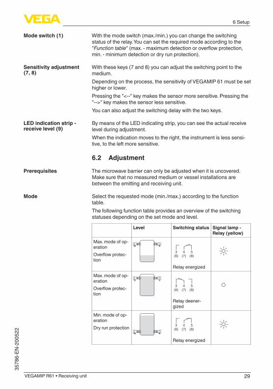
Select the requested mode (min./max.) according to the function table.The following function table provides an overview of the switching statuses depending on the set mode and level.
Level Switching status Signal lamp - Relay (yellow)
Max. mode of op-erationOverflowprotec-tion
53 4(8)(6) (7)
Relayenergized
Max. mode of op-erationOverflowprotec-tion
53 4(8)(6) (7)
Relay deener-gized
Min. mode of op-erationDry run protection 53 4
(8)(6) (7)
Relayenergized
Mode switch (1)
Sensitivity adjustment (7, 8)
LED indication strip - receive level (9)
Prerequisites
Mode
30
6 Setup
VEGAMIP R61 • Receiving unit
35786-EN-200522
Level Switching status Signal lamp - Relay (yellow)
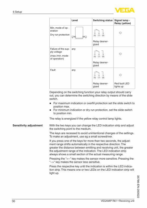
Min. mode of op-erationDry run protection 53 4
(8)(6) (7)
Relay deener-gized
Failure of the sup-ply voltage(max./min. mode of operation)
any
53 4(8)(6) (7)
Relay deener-gized
Fault any
53 4(8)(6) (7)
Relay deener-gized
Red fault LED lights up
Depending on the switching function your relay output should carry out, you can determine the switching direction by means of the slide switch.
• Formaximumindicationoroverfillprotectionsettheslideswitchtoposition max.
• For minimum indication or dry run protection, set the slide switch to position min.
Therelayisenergizediftheyellowrelaycontrollamplights.
With the two keys you can change the LED indication strip and adjust the switching point to the medium.The keys are recessed to avoid unintentional changes of the settings. To make an adjustment, use eg a small screwdriver.If you press one of the keys for more than two seconds, the adjust-ment range shifts automatically in the respective direction. The greater the distance between emitting and receiving unit, the greater the adjustment range of the indication. The LED indication strip always shows a small section of the actual measuring range.Pressing the "<--" key makes the sensor more sensitive. Pressing the "-->" key makes the sensor less sensitive.Press the respective key until the indication is within the LED indica-tion strip. This means one or two LEDs on the LED indication strip will light up.
Sensitivity adjustment
31
6 Setup
VEGAMIP R61 • Receiving unit
3578
6-EN
-200
522
CBA
2 3
1 1 1
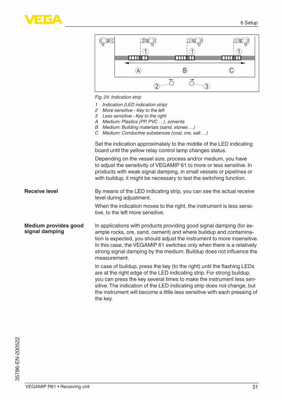
Fig. 24: Indication strip1 Indication (LED indication strip)2 More sensitive - Key to the left3 Less sensitive - Key to the rightA Medium: Plastics (PP, PVC …), solventsB Medium: Building materials (sand, stones …)C Medium: Conductive substances (coal, ore, salt …)
Set the indication approximately to the middle of the LED indicating board until the yellow relay control lamp changes status.Dependingonthevesselsize,processand/ormedium,youhaveto adjust the sensitivity of VEGAMIP 61 to more or less sensitive. In products with weak signal damping, in small vessels or pipelines or with buildup, it might be necessary to test the switching function.
By means of the LED indicating strip, you can see the actual receive level during adjustment.When the indication moves to the right, the instrument is less sensi-tive, to the left more sensitive.
In applications with products providing good signal damping (for ex-ample rocks, ore, sand, cement) and where buildup and contamina-tion is expected, you should adjust the instrument to more insensitive. In this case, the VEGAMIP 61 switches only when there is a relatively strongsignaldampingbythemedium.Buildupdoesnotinfluencethemeasurement.Incaseofbuildup,pressthekey(totheright)untiltheflashingLEDsare at the right edge of the LED indicating strip. For strong buildup, you can press the key several times to make the instrument less sen-sitive. The indication of the LED indicating strip does not change, but the instrument will become a little less sensitive with each pressing of the key.
Receive level
Medium provides good signal damping
32
6 Setup
VEGAMIP R61 • Receiving unit
35786-EN-200522
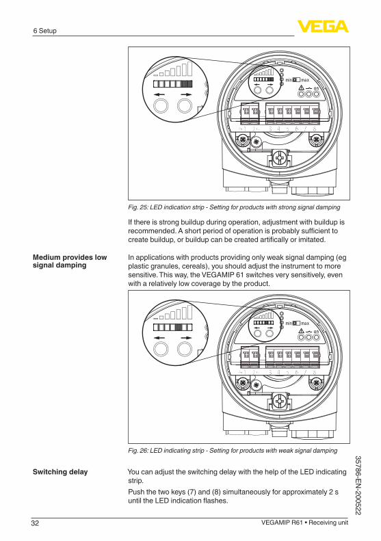
Fig. 25: LED indication strip - Setting for products with strong signal damping
If there is strong buildup during operation, adjustment with buildup is recommended.Ashortperiodofoperationisprobablysufficienttocreatebuildup,orbuildupcanbecreatedartificallyorimitated.
In applications with products providing only weak signal damping (eg plastic granules, cereals), you should adjust the instrument to more sensitive. This way, the VEGAMIP 61 switches very sensitively, even with a relatively low coverage by the product.
Fig. 26: LED indicating strip - Setting for products with weak signal damping
You can adjust the switching delay with the help of the LED indicating strip.Push the two keys (7) and (8) simultaneously for approximately 2 s untiltheLEDindicationflashes.
Medium provides low signal damping
Switching delay
33
6 Setup
VEGAMIP R61 • Receiving unit
3578
6-EN
-200
522
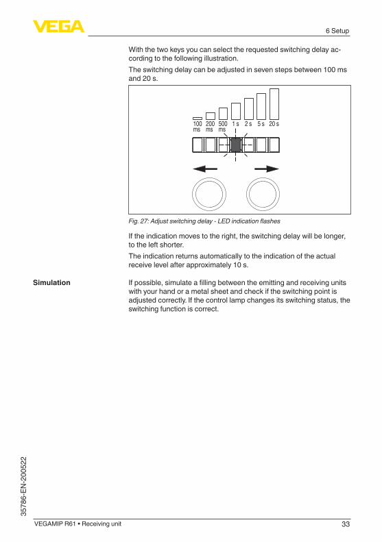
With the two keys you can select the requested switching delay ac-cording to the following illustration.The switching delay can be adjusted in seven steps between 100 ms and 20 s.
200ms
100ms
500ms
1 s 2 s 5 s 20 s
Fig. 27: Adjust switching delay - LED indication flashes
If the indication moves to the right, the switching delay will be longer, to the left shorter.The indication returns automatically to the indication of the actual receive level after approximately 10 s.
Ifpossible,simulateafillingbetweentheemittingandreceivingunitswith your hand or a metal sheet and check if the switching point is adjusted correctly. If the control lamp changes its switching status, the switching function is correct.
Simulation
34
7Maintenanceandfaultrectification
VEGAMIP R61 • Receiving unit
35786-EN-200522
7 Maintenanceandfaultrectification
7.1 MaintenanceIf the device is used properly, no special maintenance is required in normal operation.
The cleaning helps that the type label and markings on the instrument are visible.Take note of the following:
• Use only cleaning agents which do not corrode the housings, type label and seals
• Use only cleaning methods corresponding to the housing protec-tion rating
7.2 Rectify faultsThe operator of the system is responsible for taking suitable meas-ures to rectify faults.
Thefirstmeasuretotakeistochecktheoutputsignal.Inmanycases,thecausescanbedeterminedthiswayandthefaultsquicklyrectified.
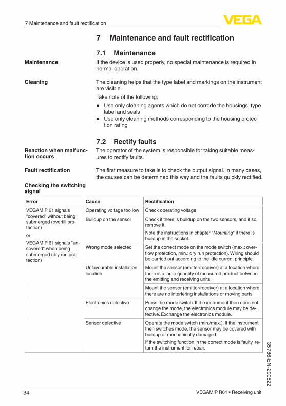
Error Cause Rectification
VEGAMIP 61 signals "covered" without being submerged(overfillpro-tection)orVEGAMIP 61 signals "un-covered" when being submerged (dry run pro-tection)
Operating voltage too low Check operating voltage
Buildup on the sensor Check if there is buildup on the two sensors, and if so, remove it.Note the instructions in chapter "Mounting" if there is buildup in the socket.
Wrong mode selected Set the correct mode on the mode switch (max.: over-flowprotection,min.:dryrunprotection).Wiringshouldbe carried out according to the idle current principle.
Unfavourable installation location
Mount the sensor (emitter/receiver) at a location where there is a large quantity of measured product between the emitting and receiving units.
Mount the sensor (emitter/receiver) at a location where there are no interfering installations or moving parts.
Electronics defective Press the mode switch. If the instrument then does not change the mode, the electronics module may be de-fective. Exchange the electronics module.
Sensor defective Operate the mode switch (min./max.). If the instrument then switches mode, the sensor may be covered with buildup or mechanically damaged.If the switching function in the correct mode is faulty, re-turn the instrument for repair.
Maintenance
Cleaning
Reaction when malfunc-tion occurs
Faultrectification
Checking the switching signal
35
7Maintenanceandfaultrectification
VEGAMIP R61 • Receiving unit
3578
6-EN
-200
522
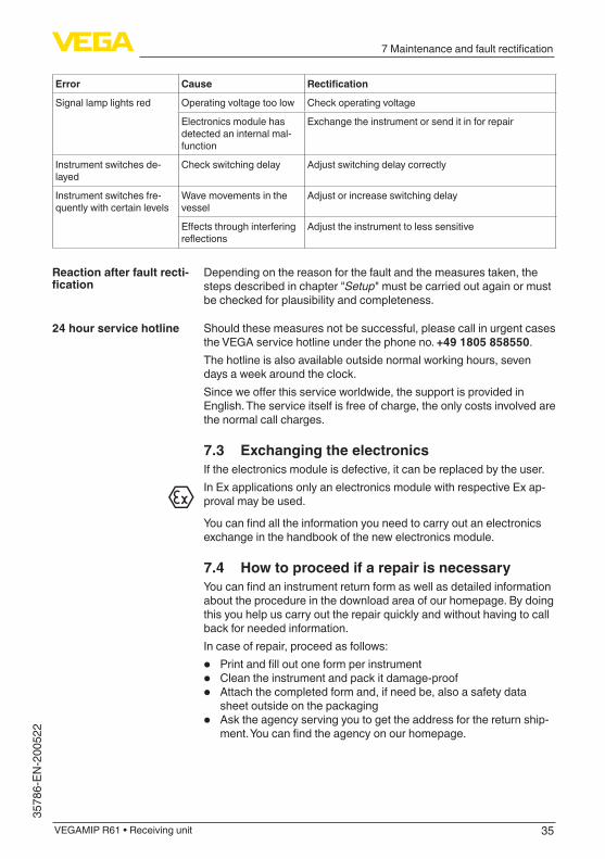
Error Cause Rectification
Signal lamp lights red Operating voltage too low Check operating voltage
Electronics module has detected an internal mal-function
Exchange the instrument or send it in for repair
Instrument switches de-layed
Check switching delay Adjust switching delay correctly
Instrument switches fre-quently with certain levels
Wave movements in the vessel
Adjust or increase switching delay
Effectsthroughinterferingreflections
Adjust the instrument to less sensitive
Depending on the reason for the fault and the measures taken, the steps described in chapter "Setup" must be carried out again or must be checked for plausibility and completeness.
Should these measures not be successful, please call in urgent cases the VEGA service hotline under the phone no. +49 1805 858550.The hotline is also available outside normal working hours, seven days a week around the clock.Sinceweofferthisserviceworldwide,thesupportisprovidedinEnglish. The service itself is free of charge, the only costs involved are the normal call charges.
7.3 Exchanging the electronicsIf the electronics module is defective, it can be replaced by the user.In Ex applications only an electronics module with respective Ex ap-proval may be used.
Youcanfindalltheinformationyouneedtocarryoutanelectronicsexchange in the handbook of the new electronics module.
7.4 How to proceed if a repair is necessaryYoucanfindaninstrumentreturnformaswellasdetailedinformationabout the procedure in the download area of our homepage. By doing this you help us carry out the repair quickly and without having to call back for needed information.In case of repair, proceed as follows:
• Printandfilloutoneformperinstrument• Clean the instrument and pack it damage-proof• Attach the completed form and, if need be, also a safety data
sheet outside on the packaging• Ask the agency serving you to get the address for the return ship-
ment.Youcanfindtheagencyonourhomepage.
Reaction after fault recti-fication
24 hour service hotline
36
8 Dismount
VEGAMIP R61 • Receiving unit
35786-EN-200522
8 Dismount
8.1 Dismounting stepsWarning:Before dismounting, be aware of dangerous process conditions such as e.g. pressure in the vessel or pipeline, high temperatures, cor-rosive or toxic media etc.
Take note of chapters "Mounting" and "Connecting to voltage supply" and carry out the listed steps in reverse order.
8.2 DisposalThe instrument consists of materials which can be recycled by spe-cialised recycling companies. We use recyclable materials and have designed the electronics to be easily separable.
WEEE directiveThe instrument does not fall in the scope of the EU WEEE directive. Article 2 of this Directive exempts electrical and electronic equipment from this requirement if it is part of another instrument that does not fall in the scope of the Directive. These include stationary industrial plants.Pass the instrument directly on to a specialised recycling company and do not use the municipal collecting points.If you have no way to dispose of the old instrument properly, please contact us concerning return and disposal.
37
9 Supplement
VEGAMIP R61 • Receiving unit
3578
6-EN
-200
522
9 Supplement
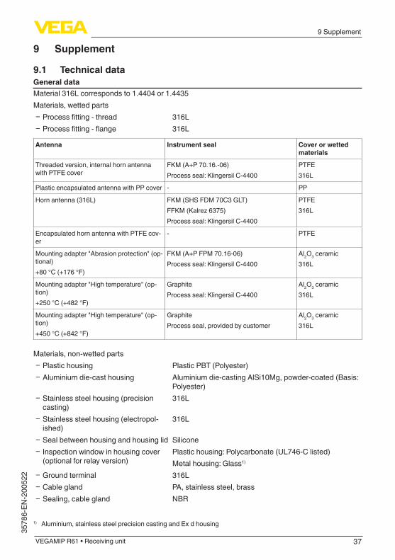
9.1 Technical dataGeneral dataMaterial 316L corresponds to 1.4404 or 1.4435Materials, wetted parts
Ʋ Processfitting-thread 316L Ʋ Processfitting-flange 316L
Antenna Instrument seal Cover or wetted materials
Threaded version, internal horn antenna with PTFE cover
FKM (A+P 70.16.-06)Process seal: Klingersil C-4400
PTFE316L
Plastic encapsulated antenna with PP cover - PP
Horn antenna (316L) FKM (SHS FDM 70C3 GLT)FFKM(Kalrez6375)Process seal: Klingersil C-4400
PTFE316L
Encapsulated horn antenna with PTFE cov-er
- PTFE
Mounting adapter "Abrasion protection" (op-tional)+80 °C (+176 °F)
FKM (A+P FPM 70.16-06)Process seal: Klingersil C-4400
Al2O3 ceramic316L
Mounting adapter "High temperature" (op-tion)+250 °C (+482 °F)
GraphiteProcess seal: Klingersil C-4400
Al2O3 ceramic316L
Mounting adapter "High temperature" (op-tion)+450 °C (+842 °F)
GraphiteProcess seal, provided by customer
Al2O3 ceramic316L
Materials, non-wetted parts Ʋ Plastic housing Plastic PBT (Polyester) Ʋ Aluminium die-cast housing Aluminium die-casting AlSi10Mg, powder-coated (Basis:
Polyester) Ʋ Stainless steel housing (precision casting)
316L
Ʋ Stainless steel housing (electropol-ished)
316L
Ʋ Seal between housing and housing lid Silicone Ʋ Inspection window in housing cover (optional for relay version)
Plastic housing: Polycarbonate (UL746-C listed)Metal housing: Glass1)
Ʋ Ground terminal 316L Ʋ Cable gland PA, stainless steel, brass Ʋ Sealing, cable gland NBR
1) Aluminium, stainless steel precision casting and Ex d housing
38
9 Supplement
VEGAMIP R61 • Receiving unit
35786-EN-200522
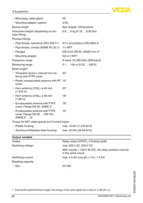
Ʋ Blind plug, cable gland PA Ʋ Mounting adapter (option) 316L
Sensor length See chapter "Dimensions"Instrument weight (depending on pro-cessfitting)
0.8 … 4 kg (0.18 … 8.82 lbs)
Processfittings Ʋ Pipe thread, cylindrical (ISO 228 T1) G1½ according to DIN 3852-A Ʋ Pipe thread, conical (ASME B1.20.1) 1½ NPT Ʋ Flanges DIN from DN 50, ASME from 2" Ʋ Mounting adapter G2 or 2 NPT
Frequency range Kband,24.085GHz(ISMband)Measuring range 0.1 … 100 m (0.33 … 328 ft)Beam angle2)
Ʋ Threaded version, internal horn an-tenna with PTFE cover
20°
Ʋ Plastic encapsulated antenna with PP cover
10°
Ʋ Horn antenna (316L), ø 40 mm (1.575 in)
22°
Ʋ Horn antenna (316L), ø 48 mm (1.89 in)
18°
Ʋ Encapsulated antenna with PTFE cover, Flange DN 50, ASME 2"
18°
Ʋ Encapsulated antenna with PTFE cover, Flange DN 80 … DN 150, ASME 3" … 6"
10°
Torque for NPT cable glands and Conduit tubes Ʋ Plastic housing max. 10 Nm (7.376 lbf ft) Ʋ Aluminium/Stainless steel housing max. 50 Nm (36.88 lbf ft)
Output variableOutput Relayoutput(DPDT),2floatingspdtsSwitching voltage max. 253 V AC, 253 V DC
With circuits > 150 V AC/DC, the relay contacts must be in the same circuit.
Switching current max. 5 A AC (cos phi > 0.5), 1 A DCBreaking capacity
Ʋ Min. 50 mW
2) Outsidethespecifiedbeamangle,theenergyoftheradarsignalhasalevelof-3dB(50%).
39
9 Supplement
VEGAMIP R61 • Receiving unit
3578
6-EN
-200
522
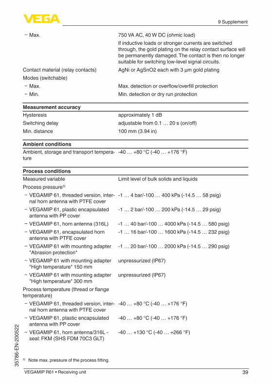
Ʋ Max. 750 VA AC, 40 W DC (ohmic load)If inductive loads or stronger currents are switched through, the gold plating on the relay contact surface will be permanently damaged. The contact is then no longer suitable for switching low-level signal circuits.
Contact material (relay contacts) AgNi or AgSnO2 each with 3 µm gold platingModes (switchable)
Ʋ Max. Max.detectionoroverflow/overfillprotection Ʋ Min. Min. detection or dry run protection
Measurement accuracyHysteresis approximately 1 dBSwitching delay adjustablefrom0.1…20s(on/off)Min. distance 100 mm (3.94 in)
Ambient conditionsAmbient, storage and transport tempera-ture
-40 … +80 °C (-40 … +176 °F)
Process conditionsMeasured variable Limit level of bulk solids and liquidsProcess pressure3)
Ʋ VEGAMIP 61, threaded version, inter-nal horn antenna with PTFE cover
-1 … 4 bar/-100 … 400 kPa (-14.5 … 58 psig)
Ʋ VEGAMIP 61, plastic encapsulated antenna with PP cover
-1 … 2 bar/-100 … 200 kPa (-14.5 … 29 psig)
Ʋ VEGAMIP 61, horn antenna (316L) -1 … 40 bar/-100 … 4000 kPa (-14.5 … 580 psig) Ʋ VEGAMIP 61, encapsulated horn antenna with PTFE cover
-1 … 16 bar/-100 … 1600 kPa (-14.5 … 232 psig)
Ʋ VEGAMIP 61 with mounting adapter "Abrasion protection"
-1 … 20 bar/-100 … 2000 kPa (-14.5 … 290 psig)
Ʋ VEGAMIP 61 with mounting adapter "High temperature" 150 mm
unpressurized(IP67)
Ʋ VEGAMIP 61 with mounting adapter "High temperature" 300 mm
unpressurized(IP67)
Processtemperature(threadorflangetemperature)
Ʋ VEGAMIP 61, threaded version, inter-nal horn antenna with PTFE cover
-40 … +80 °C (-40 … +176 °F)
Ʋ VEGAMIP 61, plastic encapsulated antenna with PP cover
-40 … +80 °C (-40 … +176 °F)
Ʋ VEGAMIP 61, horn antenna/316L - seal: FKM (SHS FDM 70C3 GLT)
-40 … +130 °C (-40 … +266 °F)
3) Notemax.pressureoftheprocessfitting.
40
9 Supplement
VEGAMIP R61 • Receiving unit
35786-EN-200522
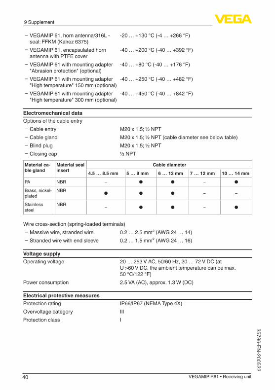
Ʋ VEGAMIP 61, horn antenna/316L - seal:FFKM(Kalrez6375)
-20 … +130 °C (-4 … +266 °F)
Ʋ VEGAMIP 61, encapsulated horn antenna with PTFE cover
-40 … +200 °C (-40 … +392 °F)
Ʋ VEGAMIP 61 with mounting adapter "Abrasion protection" (optional)
-40 … +80 °C (-40 … +176 °F)
Ʋ VEGAMIP 61 with mounting adapter "High temperature" 150 mm (optional)
-40 … +250 °C (-40 … +482 °F)
Ʋ VEGAMIP 61 with mounting adapter "High temperature" 300 mm (optional)
-40 … +450 °C (-40 … +842 °F)
Electromechanical dataOptions of the cable entry
Ʋ Cable entry M20 x 1.5; ½ NPT Ʋ Cable gland M20 x 1.5; ½ NPT (cable diameter see below table) Ʋ Blind plug M20 x 1.5; ½ NPT Ʋ Closing cap ½ NPT
Material ca-ble gland
Material seal insert
Cable diameter
4.5 … 8.5 mm 5 … 9 mm 6 … 12 mm 7 … 12 mm 10 … 14 mm
PA NBR – ● ● – ●
Brass, nickel-plated
NBR ● ● ● – –
Stainless steel
NBR – ● ● – ●
Wire cross-section (spring-loaded terminals) Ʋ Massive wire, stranded wire 0.2 … 2.5 mm² (AWG 24 … 14) Ʋ Stranded wire with end sleeve 0.2 … 1.5 mm² (AWG 24 … 16)
Voltage supplyOperating voltage 20…253VAC,50/60Hz,20…72VDC(at
U >60 V DC, the ambient temperature can be max. 50 °C/122 °F)
Power consumption 2.5 VA (AC), approx. 1.3 W (DC)
Electrical protective measuresProtection rating IP66/IP67(NEMAType4X)Overvoltage category IIIProtection class I
41
9 Supplement
VEGAMIP R61 • Receiving unit
3578
6-EN
-200
522
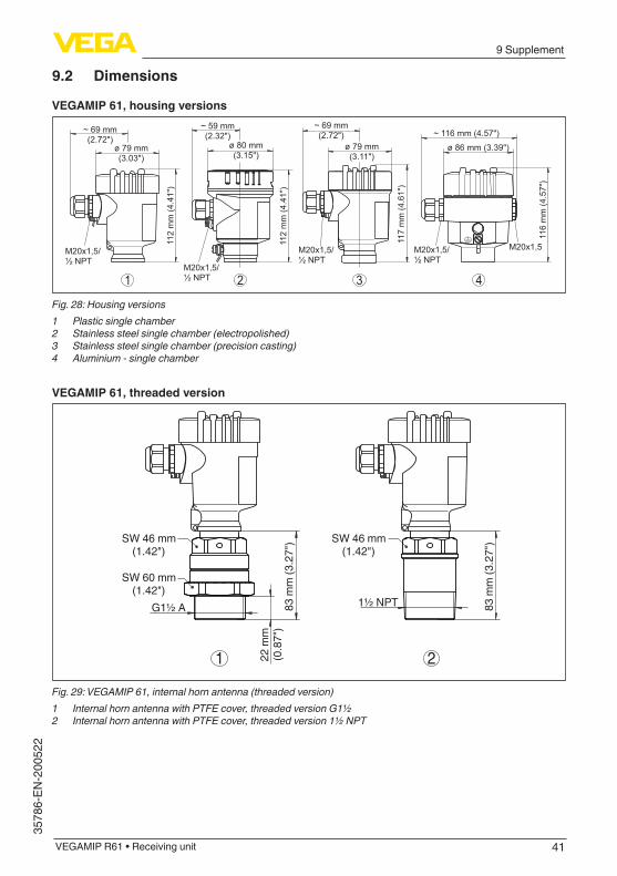
9.2 Dimensions
VEGAMIP 61, housing versions
321 4
~ 69 mm(2.72")
ø 79 mm(3.11")
117
mm
(4.6
1")
M20x1,5/½ NPT
~ 59 mm(2.32")
ø 80 mm(3.15")
112
mm
(4.4
1")
M20x1,5/½ NPT
~ 69 mm(2.72")
ø 79 mm(3.03")
112
mm
(4.4
1")
M20x1,5/½ NPT
~ 116 mm (4.57")
ø 86 mm (3.39")
116
mm
(4.5
7")
M20x1,5M20x1,5/½ NPT
Fig. 28: Housing versions1 Plastic single chamber2 Stainless steel single chamber (electropolished)3 Stainless steel single chamber (precision casting)4 Aluminium - single chamber
VEGAMIP 61, threaded version
22�m
m(0
.87"
)83
�mm
(3.2
7") SW 46 mm
(1.42") SW 46 mm
(1.42")
SW 60 mm(1.42")
G1½ A 1½ NPT 83�m
m (3
.27"
)
1 2
Fig. 29: VEGAMIP 61, internal horn antenna (threaded version)1 Internal horn antenna with PTFE cover, threaded version G1½2 Internal horn antenna with PTFE cover, threaded version 1½ NPT
42
9 Supplement
VEGAMIP R61 • Receiving unit
35786-EN-200522
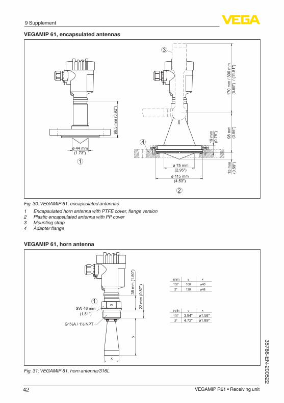
VEGAMIP 61, encapsulated antennas
2
1
4
3
15 m
m(0
.59"
)98
mm
(3.8
6")
170
mm
/ 30
0 m
m(6
.69"
) / (
11.8
1")
19 m
m(0
.75"
)
ø 75 mm(2.95")
ø 115 mm(4.53")
99,5
mm
(3.9
2")
ø 44 mm(1.73")
Fig. 30: VEGAMIP 61, encapsulated antennas1 Encapsulated horn antenna with PTFE cover, flange version2 Plastic encapsulated antenna with PP cover3 Mounting strap4 Adapter flange
VEGAMIP 61, horn antenna
mm
inch
38 m
m (1
.50"
)
22 m
m (0
.87"
)
SW 46 mm(1.81") 3.94" ø1.58"
ø1.89"4.72"
xy100 ø40120 ø48
1½"2"
xy1½"2"
x
y
G1½A / 1½ NPT
1
Fig. 31: VEGAMIP 61, horn antenna/316L
43
9 Supplement
VEGAMIP R61 • Receiving unit
3578
6-EN
-200
522
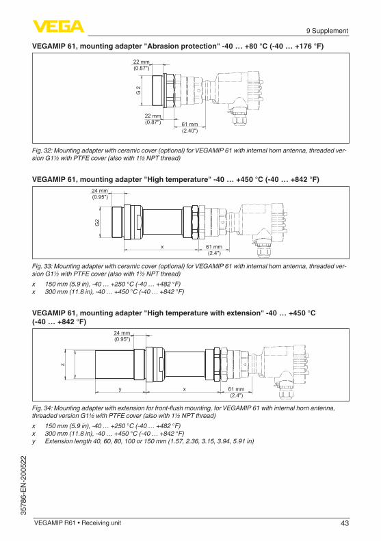
VEGAMIP 61, mounting adapter "Abrasion protection" -40 … +80 °C (-40 … +176 °F)
G 2
61 mm(2.40")
22 mm(0.87")
22 mm(0.87")
Fig. 32: Mounting adapter with ceramic cover (optional) for VEGAMIP 61 with internal horn antenna, threaded ver-sion G1½ with PTFE cover (also with 1½ NPT thread)
VEGAMIP 61, mounting adapter "High temperature" -40 … +450 °C (-40 … +842 °F)24 mm(0.95")
x 61 mm(2.4")
G2
Fig. 33: Mounting adapter with ceramic cover (optional) for VEGAMIP 61 with internal horn antenna, threaded ver-sion G1½ with PTFE cover (also with 1½ NPT thread)x 150 mm (5.9 in), -40 … +250 °C (-40 … +482 °F)x 300 mm (11.8 in), -40 … +450 °C (-40 … +842 °F)
VEGAMIP 61, mounting adapter "High temperature with extension" -40 … +450 °C (-40 … +842 °F)
24 mm(0.95")
x 61 mm(2.4")
y
z
Fig. 34: Mounting adapter with extension for front-flush mounting, for VEGAMIP 61 with internal horn antenna, threaded version G1½ with PTFE cover (also with 1½ NPT thread)x 150 mm (5.9 in), -40 … +250 °C (-40 … +482 °F)x 300 mm (11.8 in), -40 … +450 °C (-40 … +842 °F)y Extension length 40, 60, 80, 100 or 150 mm (1.57, 2.36, 3.15, 3.94, 5.91 in)
44
9 Supplement
VEGAMIP R61 • Receiving unit
35786-EN-200522
9.3 Industrial property rightsVEGA product lines are global protected by industrial property rights. Further information see www.vega.com.VEGA Produktfamilien sind weltweit geschützt durch gewerbliche Schutzrechte.Nähere Informationen unter www.vega.com.Les lignes de produits VEGA sont globalement protégées par des droits de propriété intellec-tuelle. Pour plus d'informations, on pourra se référer au site www.vega.com.VEGA lineas de productos están protegidas por los derechos en el campo de la propiedad indus-trial. Para mayor información revise la pagina web www.vega.com.Линии продукции фирмы ВЕГА защищаются по всему миру правами на интеллектуальную собственность. Дальнейшую информацию смотрите на сайте www.vega.com.VEGA系列产品在全球享有知识产权保护。进一步信息请参见网站<www.vega.com。
9.4 TrademarkAll the brands as well as trade and company names used are property of their lawful proprietor/originator.
45
INDEX
VEGAMIP R61 • Receiving unit
3578
6-EN
-200
522
INDEX
AAbrasion 18Abrasion protection 11Adjustment 28, 29Application area 8
BBending 22Buildup 17
CCable 24Cable screening 24
EElectronics module 35Emitting unit 9
FFaultrectification34Filling opening 14Functional principle 10
MMedium 13Mode 29Mounting adapter 11, 19
OOrientation of the sensor 20
PPipelines 15Polarisation direction 20Potential equalisation 24
RReceiving unit 9, 26, 28Repair 35
SSensitivity adjustment 30Service hotline 35Shielding 24Simulation 33Switching delay 32Switching point 13
TThreaded version 16
Type label 8Type of vessel
– Concrete vessel 15 – Metal vessels 14 – Non-metallic vessels 14 – Wood vessels 15
VVibrations 20
WWiring plan 26
46
Notes
VEGAMIP R61 • Receiving unit
35786-EN-200522
47
Notes
VEGAMIP R61 • Receiving unit
3578
6-EN
-200
522

Printing date:
VEGA Grieshaber KGAm Hohenstein 11377761 SchiltachGermany
3578
6-EN
-200
522
All statements concerning scope of delivery, application, practical use and operat-ing conditions of the sensors and processing systems correspond to the information available at the time of printing.Subject to change without prior notice
© VEGA Grieshaber KG, Schiltach/Germany 2020
Phone +49 7836 50-0Fax +49 7836 50-201E-mail: [email protected]