Embed Size (px)
Citation preview
Operating InstructionsVEGADIS 61
Indicationand adjustment
Contents
1 About this document
1.1 Function. . . . . . . . . . . . . . . . . . . . . . . . . . . . . . . . . . 4
1.2 Target group . . . . . . . . . . . . . . . . . . . . . . . . . . . . . . 4
1.3 Symbolism used. . . . . . . . . . . . . . . . . . . . . . . . . . . . 4
2 For your safety
2.1 Authorised personnel . . . . . . . . . . . . . . . . . . . . . . . . 5
2.2 Appropriate use . . . . . . . . . . . . . . . . . . . . . . . . . . . . 5
2.3 Warning about misuse . . . . . . . . . . . . . . . . . . . . . . . 5
2.4 General safety instructions . . . . . . . . . . . . . . . . . . . . 5
2.5 Safety approval markings and safety tips . . . . . . . . . . 6
2.6 CE conformity . . . . . . . . . . . . . . . . . . . . . . . . . . . . . 6
2.7 Safety instructions for Ex areas . . . . . . . . . . . . . . . . . 6
2.8 Environmental instructions. . . . . . . . . . . . . . . . . . . . . 6
3 Product description
3.1 Configuration . . . . . . . . . . . . . . . . . . . . . . . . . . . . . . 7
3.2 Principle of operation . . . . . . . . . . . . . . . . . . . . . . . . 8
3.3 Operation. . . . . . . . . . . . . . . . . . . . . . . . . . . . . . . . . 9
3.4 Packaging, transport and storage . . . . . . . . . . . . . . . 9
4 Mounting
4.1 General instructions . . . . . . . . . . . . . . . . . . . . . . . . . 10
4.2 Mounting instructions . . . . . . . . . . . . . . . . . . . . . . . . 10
5 Connecting to power supply
5.1 Preparing the connection . . . . . . . . . . . . . . . . . . . . . 12
5.2 Connection procedure. . . . . . . . . . . . . . . . . . . . . . . . 13
5.3 Wiring plan. . . . . . . . . . . . . . . . . . . . . . . . . . . . . . . . 14
6 Set up with the indicating and adjustment module PLICSCOM
6.1 Short description . . . . . . . . . . . . . . . . . . . . . . . . . . . 17
6.2 Insert indicating and adjustment module PLICSCOM . 17
6.3 Adjustment system . . . . . . . . . . . . . . . . . . . . . . . . . . 18
6.4 Setup procedure. . . . . . . . . . . . . . . . . . . . . . . . . . . . 19
7 Maintenance and fault rectification
7.1 Maintenance . . . . . . . . . . . . . . . . . . . . . . . . . . . . . . 20
7.2 Remove interferences . . . . . . . . . . . . . . . . . . . . . . . . 20
7.3 Instrument repair . . . . . . . . . . . . . . . . . . . . . . . . . . . 20
8 Dismounting
8.1 Dismounting steps . . . . . . . . . . . . . . . . . . . . . . . . . . 22
8.2 Disposal . . . . . . . . . . . . . . . . . . . . . . . . . . . . . . . . . 22
9 Supplement
9.1 Technical data . . . . . . . . . . . . . . . . . . . . . . . . . . . . . 23
2 VEGADIS 61
Contents27720-EN-081201

9.2 Dimensions . . . . . . . . . . . . . . . . . . . . . . . . . . . . . . . 25
9.3 Industrial property rights . . . . . . . . . . . . . . . . . . . . . . 27
9.4 Trademark . . . . . . . . . . . . . . . . . . . . . . . . . . . . . . . . 27
Supplementary documentation
Information:
Supplementary documents appropriate to the ordered version come
with the delivery. You can find them listed in chapter "Product
description".
VEGADIS 61 3
Contents
27720-EN-081201
1 About this document
1.1 Function
This operating instructions manual provides all the information you
need for mounting, connection and setup as well as important
instructions for maintenance and fault rectification. Please read this
information before putting the instrument into operation and keep this
manual accessible in the immediate vicinity of the device.
1.2 Target group
This operating instructions manual is directed to trained qualified
personnel. The contents of this manual should be made available to
these personnel and put into practice by them.
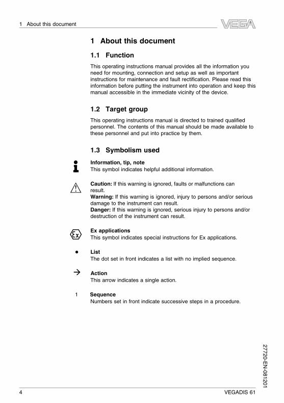
1.3 Symbolism used
Information, tip, note
This symbol indicates helpful additional information.
Caution: If this warning is ignored, faults or malfunctions can
result.
Warning: If this warning is ignored, injury to persons and/or serious
damage to the instrument can result.
Danger: If this warning is ignored, serious injury to persons and/or
destruction of the instrument can result.
Ex applications
This symbol indicates special instructions for Ex applications.
l List
The dot set in front indicates a list with no implied sequence.
à Action
This arrow indicates a single action.
1 Sequence
Numbers set in front indicate successive steps in a procedure.
4 VEGADIS 61
1 About this document27720-EN-081201
2 For your safety
2.1 Authorised personnel
All operations described in this operating instructions manual must be
carried out only by trained specialist personnel authorised by the plant
operator.
During work on and with the device the required personal protective
equipment must always be worn.
2.2 Appropriate use
VEGADIS 61 is an external indicating and adjustment unit for VEGA
plics® sensors.
You can find detailed information on the application range in chapter
"Product description".
Operational reliability is ensured only if the instrument is properly used
according to the specifications in the operating instructions manual as
well as possible supplementary instructions.
For safety and warranty reasons, any invasive work on the device
beyond that described in the operating instructions manual may be
carried out only by personnel authorised by the manufacturer. Arbitrary
conversions or modifications are explicitly forbidden.
2.3 Warning about misuse
Inappropriate or incorrect use of the instrument can give rise to
application-specific hazards, e.g. vessel overfill or damage to system
components through incorrect mounting or adjustment.
2.4 General safety instructions
This is a high-tech instrument requiring the strict observance of
standard regulations and guidelines. The user must take note of the
safety instructions in this operating instructions manual, the country-
specific installation standards as well as all prevailing safety
regulations and accident prevention rules.
The instrument must only be operated in a technically flawless and
reliable condition. The operator is responsible for trouble-free
operation of the instrument.
During the entire duration of use, the user is obliged to determine the
compliance of the required occupational safety measures with the
current valid rules and regulations and also take note of new
regulations.
VEGADIS 61 5
2 For your safety
27720-EN-081201
2.5 Safety approval markings and safety tips
The safety approval markings and safety tips on the device must be
observed.
2.6 CE conformity
The instrument is in CE conformity with EMC (89/336/EWG), fulfils
NAMUR recommendation NE 21 and is in CE conformity with LVD (73/
23/EG).
Conformity has been judged according to the following standards:
l EMC:
- Emission EN 61326: 1997 (class B)
- Susceptibility EN 61326: 1997/A1:1998
l LVD: EN 61010: 2001
2.7 Safety instructions for Ex areas
Please note the Ex-specific safety information for installation and
operation in Ex areas. These safety instructions are part of the
operating instructions manual and come with the Ex-approved
instruments.
2.8 Environmental instructions
Protection of the environment is one of our most important duties. That
is why we have introduced an environment management system with
the goal of continuously improving company environmental protection.
The environment management system is certified according to DIN
EN ISO 14001.
Please help us fulfil this obligation by observing the environmental
instructions in this manual:
l Chapter "Packaging, transport and storage"
l Chapter "Disposal"
6 VEGADIS 61
2 For your safety27720-EN-081201

3 Product description
3.1 Configuration
The scope of delivery encompasses:
l Indicating and adjustment unit VEGADIS 61
l Cable entry M20x1 for the sensor
l Documentation
- this operating instructions manual
- Operating instructions manual 27835 "Indicating and adjust-
ment module PLICSCOM"
- Supplementary instructions manual - 31708 "Heating for
indicating and adjustment module PLICSCOM" (optional)
- Ex-specific "Safety instructions" (with Ex-versions)
- if necessary, further certificates
VEGADIS 61 consists of the following components:
l Mounting element (according to the order specification mounting
plate for wall mounting, clip for carrier rail mounting or strap for
tube mounting)
l Housing with electronics
l Housing cover with integrated PLICSCOM
The components are available in different versions.
1
3
2
Fig. 1: VEGADIS 61 with plastic housing and mounting plate for wall mounting
1 Housing cover with integrated PLICSCOM
2 Housing with electronics
3 Mounting plate
The type label contains the most important data for identification and
use of the instrument:
l Article number
l Serial number
l Technical data
Scope of delivery
Components
Type label
VEGADIS 61 7
3 Product description
27720-EN-081201

l Article numbers documentation
With the serial number, you can access the delivery data of the
instrument via www.vega.com, "VEGA Tools" and "serial number
search". In addition to the type label outside, you can also find the
serial number on the inside of the instrument.
3.2 Principle of operation
VEGADIS 61 is an external indicating and adjustment unit for VEGA
plics® sensors.
Fig. 2: Connection of VEGADIS 61 to the sensor
VEGADIS 61 is connected to the sensor with a screened four-wire
standard cable up to 25 m long. Communication is carried out via this
cable and the VEGADIS 61 is also powered by the sensor. An
additional power supply is not necessary.
VEGADIS 61 is connected with a screened four-wire special cable of
25 m length with connection socket M12 x 1 to the sensor.
Communication is carried out via this cable and the VEGADIS 61 is
also powered by the sensor. An additional power supply is not
necessary.
Note:
This cable is absolutely necessary for reliable function of VEGADIS 61as well as the sensor.
Application area
Connectionto4…20mA/
HART sensors
Connection to PA/FF
sensors
8 VEGADIS 61
3 Product description27720-EN-081201
3.3 Operation
The respective sensor can be operated as follows via VEGADIS 61:
l with indicating and adjustment module
l an adjustment software according to FDT/DTM standard, e.g.
PACTware and PC
The entered parameters are generally saved in the respective sensor,
when used with PACTware and PC optionally also on the PC.
3.4 Packaging, transport and storage
Your instrument was protected by packaging during transport. Its
capacity to handle normal loads during transport is assured by a test
according to DIN EN 24180.
The packaging of standard instruments consists of environment-
friendly, recyclable cardboard. For special versions, PE foam or PE foil
is also used. Dispose of the packaging material via specialised
recycling companies.
Transport must be carried out under consideration of the notes on the
transport packaging. Nonobservance of these instructions can cause
damage to the device.
The delivery must be checked for completeness and possible transit
damage immediately at receipt. Ascertained transit damage or
concealed defects must be appropriately dealt with.
Up to the time of installation, the packages must be left closed and
stored according to the orientation and storage markings on the
outside.
Unless otherwise indicated, the packages must be stored only under
the following conditions:
l Not in the open
l Dry and dust free
l Not exposed to corrosive media
l Protected against solar radiation
l Avoiding mechanical shock and vibration
l Storage and transport temperature see chapter "Supplement -
Technical data - Ambient conditions"
l Relative humidity 20 … 85 %
Packaging
Transport
Transport inspection
Storage
Storage and transport
temperature
VEGADIS 61 9
3 Product description
27720-EN-081201
4 Mounting
4.1 General instructions
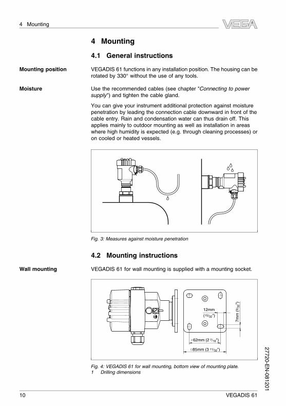
VEGADIS 61 functions in any installation position. The housing can be
rotated by 330° without the use of any tools.
Use the recommended cables (see chapter "Connecting to power
supply") and tighten the cable gland.
You can give your instrument additional protection against moisture
penetration by leading the connection cable downward in front of the
cable entry. Rain and condensation water can thus drain off. This
applies mainly to outdoor mounting as well as installation in areas
where high humidity is expected (e.g. through cleaning processes) or
on cooled or heated vessels.
Fig. 3: Measures against moisture penetration
4.2 Mounting instructions
VEGADIS 61 for wall mounting is supplied with a mounting socket.
62mm (2 7/16")
12mm
(15/32")
7m
m (
9/ 3
2")
85mm (3 11/32")
Fig. 4: VEGADIS 61 for wall mounting, bottom view of mounting plate.
1 Drilling dimensions
Mounting position
Moisture
Wall mounting
10 VEGADIS 61
4 Mounting27720-EN-081201
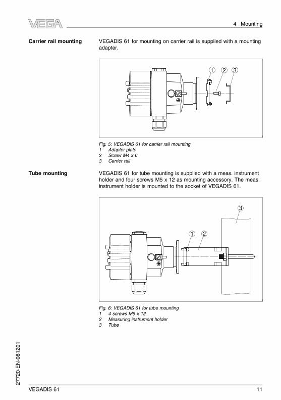
VEGADIS 61 for mounting on carrier rail is supplied with a mounting
adapter.
1 32
Fig. 5: VEGADIS 61 for carrier rail mounting
1 Adapter plate
2 Screw M4 x 6
3 Carrier rail
VEGADIS 61 for tube mounting is supplied with a meas. instrument
holder and four screws M5 x 12 as mounting accessory. The meas.
instrument holder is mounted to the socket of VEGADIS 61.
1
3
2
Fig. 6: VEGADIS 61 for tube mounting
1 4 screws M5 x 12
2 Measuring instrument holder
3 Tube
Carrier rail mounting
Tube mounting
VEGADIS 61 11
4 Mounting
27720-EN-081201
5 Connecting to power supply
5.1 Preparing the connection
Always keep in mind the following safety instructions:
l Connect only in the complete absence of line voltage
In hazardous areas you should take note of the appropriate
regulations, conformity and type approval certificates of the sensors
and power supply units.
VEGADIS 61 is connected to the sensor with standard four-wire cable
with screen.
Use cable with roundcross-section.A cable outer diameter of 5… 9mm
(0.2 … 0.35 in) ensures the seal effect of the cable gland. If you are
using cable with a different diameter or cross-section, exchange the
seal or use a suitable cable gland.
Sensors with double chamber housing can be optionally equipped with
a 4-pole plug M12 x 1 for connection of VEGADIS 61.
Tip:
We recommend using a suitable, confectioned lead cable, e.g. length
25 m, VEGA article no. ASL.1SC.
VEGADIS 61 is connected with a screened four-wire special cable of
up to 25 m length with connection socket M12 x 1 to the sensor.
PA/FF sensors with signle or double chamber housing can be
optionally equipped with a 5-pole plug M12 x 1 for connection of
VEGADIS 61.
Information:
The special cable is part of the scope of delivery of PA/FF sensors with
connection plug M12 x 1 for VEGADIS 61.
Take note of the corresponding installation regulations for Ex
applications.
Connect the cable screen on both ends to ground potential. In
VEGADIS 61 and in the sensor, the screen must be connected directly
to the internal ground terminal. The ground terminal on the outside of
the housing must be connected to the potential equalisation (low
impedance).
In Ex applications, one-sided grounding on the sensor is recommen-
ded, see EN 60079-14.
Note safety instructions
Take note of
safety instruc-
tions for Ex ap-
plications
Select connection cable
4 … 20 mA/HART sen-
sors
Select connection cable
PA/FF sensors
Select connec-
tion cable for Ex
applications
Cable screening and
grounding
Cable screen and
grounding for Ex appli-
cations
12 VEGADIS 61
5 Connecting to power supply27720-EN-081201
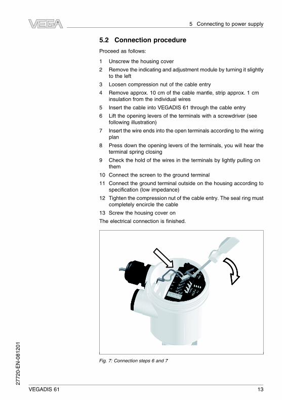
5.2 Connection procedure
Proceed as follows:
1 Unscrew the housing cover
2 Remove the indicating and adjustment module by turning it slightly
to the left
3 Loosen compression nut of the cable entry
4 Remove approx. 10 cm of the cable mantle, strip approx. 1 cm
insulation from the individual wires
5 Insert the cable into VEGADIS 61 through the cable entry
6 Lift the opening levers of the terminals with a screwdriver (see
following illustration)
7 Insert the wire ends into the open terminals according to the wiring
plan
8 Press down the opening levers of the terminals, you will hear the
terminal spring closing
9 Check the hold of the wires in the terminals by lightly pulling on
them
10 Connect the screen to the ground terminal
11 Connect the ground terminal outside on the housing according to
specification (low impedance)
12 Tighten the compression nut of the cable entry. The seal ring must
completely encircle the cable
13 Screw the housing cover on
The electrical connection is finished.
Fig. 7: Connection steps 6 and 7
VEGADIS 61 13
5 Connecting to power supply
27720-EN-081201

5.3 Wiring plan
2
1
3
Display
I2C
5 6 7 8
Fig. 8: Electronics and connection compartment
1 Spring-loaded terminals for connection to the sensor
2 Plug connector for VEGACONNECT (I²C interface)
3 Ground terminal for connection of the cable screen1)
Display
5 6 7 8
4
12
Fig. 9: Wiring plan VEGADIS 61 for 4 … 20 mA/HART sensors
1 To the sensor
2 Grounding on both ends with non-Ex. With Ex, one-sided grounding at the
sensor is recommended, see EN 60079-14.
Connection via standard cable
Connection between VEGADIS 61 and sensor is carried out according
to the chart:
1) Connect screen here. Connect ground terminal on the outside of the
housing as prescribed. The two terminals are galvanically connected.
Electronics and connec-
tion compartment
Wiring plan (4 … 20 mA/
HART sensors)
14 VEGADIS 61
5 Connecting to power supply27720-EN-081201
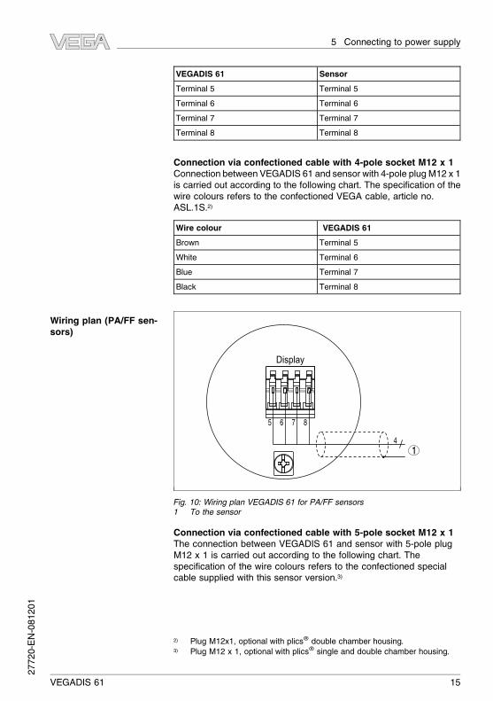
VEGADIS 61 Sensor
Terminal 5 Terminal 5
Terminal 6 Terminal 6
Terminal 7 Terminal 7
Terminal 8 Terminal 8
Connection via confectioned cable with 4-pole socket M12 x 1
Connection between VEGADIS 61 and sensor with 4-pole plugM12 x 1
is carried out according to the following chart. The specification of the
wire colours refers to the confectioned VEGA cable, article no.
ASL.1S.2)
Wire colour VEGADIS 61
Brown Terminal 5
White Terminal 6
Blue Terminal 7
Black Terminal 8
Display
5 6 7 8
4
1
Fig. 10: Wiring plan VEGADIS 61 for PA/FF sensors
1 To the sensor
Connection via confectioned cable with 5-pole socket M12 x 1
The connection between VEGADIS 61 and sensor with 5-pole plug
M12 x 1 is carried out according to the following chart. The
specification of the wire colours refers to the confectioned special
cable supplied with this sensor version.3)
2) Plug M12x1, optional with plics® double chamber housing.3) Plug M12 x 1, optional with plics® single and double chamber housing.
Wiring plan (PA/FF sen-
sors)
VEGADIS 61 15
5 Connecting to power supply
27720-EN-081201
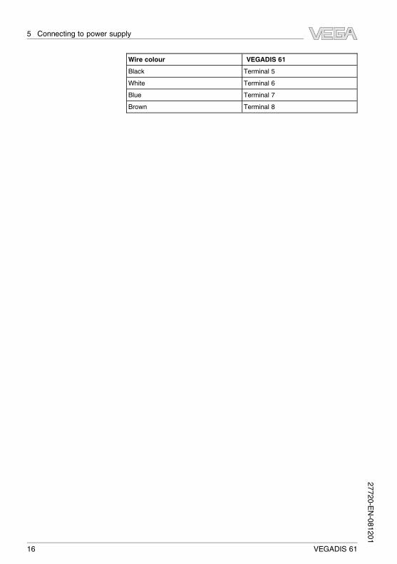
Wire colour VEGADIS 61
Black Terminal 5
White Terminal 6
Blue Terminal 7
Brown Terminal 8
16 VEGADIS 61
5 Connecting to power supply27720-EN-081201
6 Set up with the indicating and adjustment
module PLICSCOM
6.1 Short description
The indicating and adjustment module is used for measured value
display, adjustment and diagnosis. It can be mounted in the following
housing versions and instruments:
l All sensors of the plics® instrument family, in the single as well as
in the double chamber housing (optionally in the electronics or
connection compartment)
l External indicating and adjustment unit VEGADIS 61
From a hardware version …- 01 or higher of PLICSCOM as well as a
hardware version …- 01, 03 or higher of the corresponding sensor, an
integrated backlight can be switched on via the adjustment menu. The
hardware version is stated on the type label of the PLICSCOM or the
sensor electronics.
Note:
You can find detailed information on adjustment in the operating
instructions manual "Indicating and adjustment module".
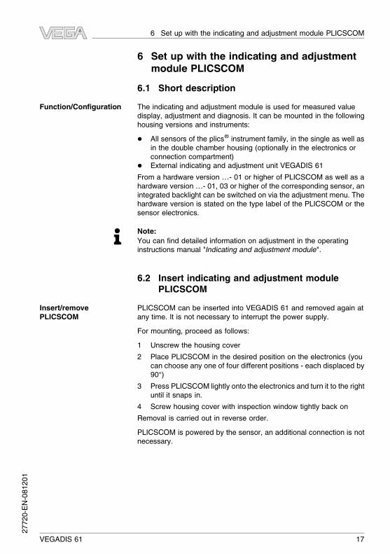
6.2 Insert indicating and adjustment module
PLICSCOM
PLICSCOM can be inserted into VEGADIS 61 and removed again at
any time. It is not necessary to interrupt the power supply.
For mounting, proceed as follows:
1 Unscrew the housing cover
2 Place PLICSCOM in the desired position on the electronics (you
can choose any one of four different positions - each displaced by
90°)
3 Press PLICSCOM lightly onto the electronics and turn it to the right
until it snaps in.
4 Screw housing cover with inspection window tightly back on
Removal is carried out in reverse order.
PLICSCOM is powered by the sensor, an additional connection is not
necessary.
Function/Configuration
Insert/remove
PLICSCOM
VEGADIS 61 17
6 Set up with the indicating and adjustment module PLICSCOM
27720-EN-081201

Fig. 11: Installation of PLICSCOM
6.3 Adjustment system
1.1
2
3
1
Fig. 12: Indicating and adjustment elements
1 LC display
2 Indication of the menu item number
3 Adjustment keys
18 VEGADIS 61
6 Set up with the indicating and adjustment module PLICSCOM
27720-EN-081201

l [OK] key:
- Move to the menu overview
- Confirm selected menu
- Edit parameter
- Save value
l [->] key to select:
- menu change
- list entry
- Select editing position
l [+] key:
- Change value of the parameter
l [ESC] key:
- interrupt input
- jump to the next higher menu
The sensor is adjusted via the four keys of the indicating and
adjustment module. The LC display indicates the individual menu
items. The functions of the individual keys are shown in the above
illustration. Approx. 10 minutes after the last pressing of a key, an
automatic reset to measured value indication is triggered. Any values
not confirmed with [OK] will not be saved.
6.4 Setup procedure
Setup and adjustment of the respective sensor is carried out according
to the operating instructions manual of the respective sensor.
Key functions
Adjustment system
VEGADIS 61 19
6 Set up with the indicating and adjustment module PLICSCOM
27720-EN-081201
7 Maintenance and fault rectification
7.1 Maintenance
When used in the correct way, no special maintenance is required in
normal operation.
7.2 Remove interferences
The operator of the system is responsible for taken suitable measures
to remove interferences.
A maximum of reliability is ensured. Nevertheless, faults can occur
during operation. These may be caused by the following, e.g.:
l Sensor
l Process
l Power supply
l Signal processing
The first measures to be taken are to check the output signals as well
as to evaluate the error messages via the indicating and adjustment
module. The procedure is described in the operating instructions of the
respective sensor. Further comprehensive diagnostics can be carried
out on a PC with the software PACTware and the suitable DTM. In
many cases, the causes can be determined in this way and faults can
be rectified.
However, should these measures not be successful, call the VEGA
service hotline in urgent cases under the phone no. +49 1805 858550.
The hotline is available to you 7 days a week round-the-clock. Since
we offer this service world-wide, the support is only available in the
English language. The service is free of charge, only the standard
telephone costs will be charged.
Depending on the failure reason and measures taken, the steps
described in chapter "Set up" must be carried out again, if necessary.
7.3 Instrument repair
If a repair is necessary, please proceed as follows:
You can download a return form (23 KB) from our Internet homepage
www.vega.com under: "Downloads - Forms and certificates - Repair
form".
By doing this you help us carry out the repair quickly and without
having to call back for needed information.
l Print and fill out one form per instrument
l Clean the instrument and pack it damage-proof
Reaction when malfunc-
tions occur
Causes of malfunction
Fault rectification
24 hour service hotline
Reaction after fault rec-
tification
20 VEGADIS 61
7 Maintenance and fault rectification27720-EN-081201

l Attach the completed form and, if need be, also a safety data
sheet outside on the packaging
l Please ask the agency serving you for the address of your return
shipment. You can find the respective agency on our website
www.vega.com under: "Company - VEGA worldwide"
VEGADIS 61 21
7 Maintenance and fault rectification
27720-EN-081201
8 Dismounting
8.1 Dismounting steps
Warning:
Before dismounting, be aware of dangerous process conditions such
as e.g. pressure in the vessel, high temperatures, corrosive or toxic
products etc.
Take note of chapters "Mounting" and "Connecting to power supply"
and carry out the listed steps in reverse order.
8.2 Disposal
The instrument consists of materials which can be recycled by
specialised recycling companies. We use recyclable materials and
have designed the electronics to be easily separable.
WEEE directive 2002/96/EG
This instrument is not subject to the WEEE directive 2002/96/EG and
the respective national laws. Pass the instrument directly on to a
specialised recycling company and do not use the municipal collecting
points. These may be used only for privately used products according
to the WEEE directive.
Correct disposal avoids negative effects to persons and environment
and ensures recycling of useful raw materials.
Materials: see chapter "Technical data"
If you have no possibility to dispose of the old instrument
professionally, please contact us concerning return and disposal.
22 VEGADIS 61
8 Dismounting27720-EN-081201
9 Supplement
9.1 Technical data
General data
316L corresponds to 1.4404 or 1.4435, 316Ti corresponds to 1.4571
Materials
- Housing plastic PBT, Alu die-casting, 316L
- Inspection window in housing cover for
indicating and adjustment module
Polycarbonate (UL-746-C listed)
- Ground terminal 316Ti/316L
Weight 0.35 kg (0.772 lbs)
Ambient conditions
Ambient temperature -15 … +70 °C (+5 … +158 °F)
Storage and transport temperature -40 … +80 °C (-40 … +176 °F)
Electromechanical data
Cable gland 1 x cable gland M20 x 1.5 (cable: ø 5 … 9 mm), 1 x
blind stopper M20 x 1.5 or 1 x closing cap ½ NPT,
1 x blind stopper ½ NPT
Spring-loaded terminals for wire cross-sec-
tion up to
2.5 mm² (AWG 14)
Indicating and adjustment module
Voltage supply and data transmission through sensor via gold-plated sliding contacts (I²C
bus)
Indication LC display in dot matrix
Adjustment elements 4 keys
Protection
- unassembled IP 20
- mounted into VEGADIS 61 without cover IP 40
Materials
- Housing ABS
- Inspection window Polyester foil
Adjustment circuit
Connection to VEGA plics® sensors
Data transmission digital (I²C-Bus)
Connection cable 4-wire, screened
Cable length max. 25 m
VEGADIS 61 23
9 Supplement
27720-EN-081201

Electrical protective measures
Protection
- Housing plastic IP 66/IP 67
- Housing Aluminium, stainless steel IP 66/IP 68 (0.2 bar)
Overvoltage category III
Protection class II
Approvals4)
ATEX ia ATEX II 1G, 2G EEx ia IIC T6
ATEX ia + D ATEX II 1G, 1/2G, 2G EEx ia IIC T5 + ATEX II 1/2 D
IP6X T
ATEX D ATEX II 1/2 D IP6X T
IEC ia IEC Ex ia IIC T6
IEC tD IEC Ex Ex tD A21 IP65 T65°
FM FM (IS) Cl.I-III, Div 1, GP ABCDEF
CSA CSA (IS) Cl.I-III, Div 1, GP ABCDEFG
4) Deviating data in Ex applications: see separate safety instructions.
24 VEGADIS 61
9 Supplement27720-EN-081201

9.2 Dimensions
VEGADIS 61 housing
1 2 3
4
12
3 m
m (
4.8
4")
12
8 m
m (
5.0
4")
11
2 m
m (
4.4
1")
12
5 m
m (
4.9
2")
~ 69 mm
(2.72")ø 77 mm
(3.03")
~ 69 mm
(2.72")
~ 59 mm
(2.32")
~ 116 mm (4.57")
ø 77 mm
(3.03")
ø 80 mm
(3.15")
ø 84 mm (3.31")
M20x1,5
M20x1,5/
½ NPT
M20x1,5/
½ NPT
M20x1,5/
½ NPT
M20x1,5/
½ NPT
Fig. 13: VEGADIS 61 housing versions
1 Plastic housing
2 Stainless steel housing - precision casting
3 Stainless steel housing, electropolished
4 Aluminium housing
VEGADIS 61 25
9 Supplement
27720-EN-081201
VEGADIS 61 mounting elements
5m
m
(13/ 6
4")
16
mm
(5/ 8
")
84mm (3 5/16")
70mm (2 3/4")
R32mm
(1 1
7 /64")
M6
67
mm
(2
41/ 6
4")
~ 1
11
mm
(4
31/ 8
")
3m
m
(1/ 8
") 11
mm
(7/ 1
6")
60mm (2 23/64")
1 2 3
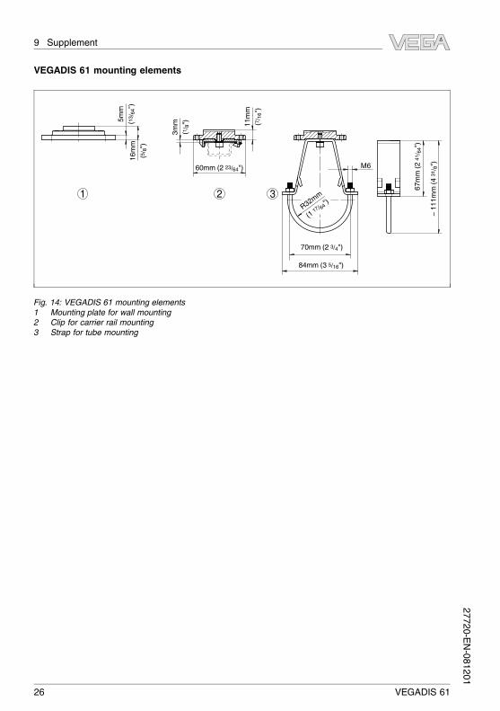
Fig. 14: VEGADIS 61 mounting elements
1 Mounting plate for wall mounting
2 Clip for carrier rail mounting
3 Strap for tube mounting
26 VEGADIS 61
9 Supplement27720-EN-081201
9.3 Industrial property rights
VEGA product lines are global protected by industrial property rights.
Further information see http://www.vega.com.
Only in U.S.A.: Further information see patent label at the sensor
housing.
VEGA Produktfamilien sind weltweit geschützt durch gewerbliche
Schutzrechte.
Nähere Informationen unter http://www.vega.com.
Les lignes de produits VEGA sont globalement protégées par des
droits de propriété intellectuelle. Pour plus d'informations, on pourra
se référer au site http://www.vega.com.
VEGA lineas de productos están protegidas por los derechos en el
campo de la propiedad industrial. Para mayor información revise la
pagina web http://www.vega.com.
Линии продукции фирмы ВЕГА защищаются по всему миру
правами на интеллектуальную собственность. Дальнейшую
информацию смотрите на сайте http://www.vega.com.
VEGA系列产品在全球享有知识产权保护。
进一步信息请参见网站<http://www.vega.com>。
9.4 Trademark
All brands used as well as trade and company names are property of
their lawful proprietor/originator.
VEGADIS 61 27
9 Supplement
27720-EN-081201
28 VEGADIS 61
9 Supplement27720-EN-081201

VEGADIS 61 29
9 Supplement
27720-EN-081201

30 VEGADIS 61
9 Supplement27720-EN-081201
VEGADIS 61 31
9 Supplement
27720-EN-081201
VEGA Grieshaber KG
Am Hohenstein 11377761 Schiltach
Germany
Phone +49 7836 50-0Fax +49 7836 50-201E-mail: [email protected]
www.vega.com
Printing date:
ISO 9001
All statements concerning scope of delivery, application,
practical use and operating conditions of the sensors and
processing systems correspond to the information avail-
able at the time of printing.
© VEGA Grieshaber KG, Schiltach/Germany 2008
Subject to change without prior notice 27720-EN-081201