Embed Size (px)
Citation preview

Compact Ejector SCPMc
Operating Instructions
WWW.SCHMALZ.COM EN-US · 30.30.01.01963 · 00 · 05/19
Note
The operating instructions were originally written in German. Store in a safe place for future reference.Subject to technical changes without notice. No responsibility is taken for printing or other types of er-rors.
Published by
© J. Schmalz GmbH, 05/19
This document is protected by copyright. J. Schmalz GmbH retains the rights established thereby. Repro-duction of the contents, in full or in part, is only permitted within the limits of the legal provisions ofcopyright law. Any modifications to or abridgments of the document are prohibited without explicit writ-ten agreement from J. Schmalz GmbH.
Contact
J. Schmalz GmbH
Johannes-Schmalz-Str. 1
72293 Glatten, Germany
T: +49 7443 2403-0
www.schmalz.com
Contact information for Schmalz companies and trade partners worldwide can be found at:
www.schmalz.com/salesnetwork
2 / 52 EN-US · 30.30.01.01963 · 00 · 05/19
Contents
EN-US · 30.30.01.01963 · 00 · 05/19 3 / 52
Contents
1 Important information ................................................................................................................................... 6
1.1 Note on Using this Document ............................................................................................................... 6
1.2 The technical documentation is part of the product ........................................................................... 6
1.3 Warnings in this document.................................................................................................................... 6
1.4 Symbol..................................................................................................................................................... 6
1.5 Type Plate ............................................................................................................................................... 7
2 Fundamental Safety Instructions................................................................................................................... 8
2.1 Emissions ................................................................................................................................................. 8
2.2 Intended Use........................................................................................................................................... 8
2.3 Non-Intended Use .................................................................................................................................. 8
2.4 Personnel Qualification.......................................................................................................................... 9
2.5 Modifications to the Ejector .................................................................................................................. 9
3 Product description....................................................................................................................................... 10
3.1 Description of the Ejector .................................................................................................................... 103.1.1 Suction of the Workpiece (Vacuum Generation) .................................................................... 103.1.2 Depositing the Workpiece/Part (Blowing Off)......................................................................... 11
3.2 Operating Modes ................................................................................................................................. 11
3.3 Ejector Designation .............................................................................................................................. 11
3.4 Ejector Structure................................................................................................................................... 12
3.5 Controls and Displays in Detail............................................................................................................ 13
4 Technical Data ............................................................................................................................................... 15
4.1 Display Parameters ............................................................................................................................... 15
4.2 General Parameters.............................................................................................................................. 15
4.3 Electrical Parameters ............................................................................................................................ 15
4.4 Mechanical Data................................................................................................................................... 164.4.1 Performance Data...................................................................................................................... 164.4.2 Dimensions................................................................................................................................. 164.4.3 Maximum Torque ...................................................................................................................... 174.4.4 Pneumatic circuit plans ............................................................................................................. 174.4.5 Factory Settings ......................................................................................................................... 18
5 Operating and Menu Concepts.................................................................................................................... 19
5.1 Button Assignments in Display Mode ................................................................................................. 195.1.1 Opening the Menu .................................................................................................................... 195.1.2 Displaying the basic settings (slide show) ................................................................................ 20
5.2 Main Menu ........................................................................................................................................... 205.2.1 Functions in the Main Menu..................................................................................................... 205.2.2 Changing the Parameters of the Main menu .......................................................................... 20
5.3 Extended Functions menu (EF) ............................................................................................................ 215.3.1 Functions in the Extended Functions menu (EF)...................................................................... 215.3.2 Changing parameters in the Extended Functions menu......................................................... 21
5.4 Info menu [INF]..................................................................................................................................... 225.4.1 Functions in the Info menu....................................................................................................... 225.4.2 How data is displayed in the info menu .................................................................................. 23
6 Description of Functions............................................................................................................................... 24
6.1 Overview of Functions ......................................................................................................................... 24
Contents
4 / 52 EN-US · 30.30.01.01963 · 00 · 05/19
6.2 Operating Modes ................................................................................................................................. 246.2.1 Automatic Mode........................................................................................................................ 246.2.2 Manual Mode ............................................................................................................................ 24
6.3 Monitoring the system vacuum and defining limit values ................................................................ 26
6.4 Calibrating the sensor .......................................................................................................................... 26
6.5 Control functions.................................................................................................................................. 266.5.1 No Control (Continuous Suction).............................................................................................. 276.5.2 Control ....................................................................................................................................... 27
6.6 Blow off modes .................................................................................................................................... 276.6.1 Externally Controlled Blow-Off ................................................................................................ 276.6.2 Internally Time-Controlled Blow-Off........................................................................................ 276.6.3 Setting the blow off time ......................................................................................................... 27
6.7 Selecting the display unit..................................................................................................................... 27
6.8 Reset to factory settings ...................................................................................................................... 28
6.9 Counters................................................................................................................................................ 28
6.10 Displaying the software version .......................................................................................................... 29
6.11 Displaying the part number................................................................................................................. 29
6.12 Displaying the serial number............................................................................................................... 30
6.13 Condition Monitoring (CM) ................................................................................................................. 316.13.1 Evacuation Time Monitoring .................................................................................................... 316.13.2 Leakage monitoring .................................................................................................................. 32
7 Transport and storage .................................................................................................................................. 33
7.1 Checking the Delivery .......................................................................................................................... 33
8 Installation..................................................................................................................................................... 34
8.1 Installation Instructions........................................................................................................................ 34
8.2 Installation ............................................................................................................................................ 34
8.3 Pneumatic Connection ......................................................................................................................... 358.3.1 Connecting the Compressed Air and Vacuum ......................................................................... 368.3.2 Instructions for the Pneumatic Connection ............................................................................. 368.3.3 Optional: External blow-off connection (EB)........................................................................... 37
8.4 Electrical Connection............................................................................................................................ 378.4.1 Pin assignments ......................................................................................................................... 38
9 Operation ...................................................................................................................................................... 40
9.1 General Preparations ........................................................................................................................... 40
9.2 Changing the Blow-Off Flow Rate on the Ejector.............................................................................. 40
10 Troubleshooting............................................................................................................................................ 41
10.1 Help with Malfunctions ....................................................................................................................... 41
10.2 Error messages...................................................................................................................................... 42
11 Maintenance.................................................................................................................................................. 43
11.1 Safety .................................................................................................................................................... 43
11.2 Cleaning the Ejector............................................................................................................................. 43
11.3 Replacing the Silencer.......................................................................................................................... 44
12 Warranty........................................................................................................................................................ 46
13 Spare and Wearing Parts, Accessories......................................................................................................... 47
13.1 Spare and Wearing Parts ..................................................................................................................... 47
13.2 Accessories ............................................................................................................................................ 47
Contents
EN-US · 30.30.01.01963 · 00 · 05/19 5 / 52
14 Decommissioning and recycling .................................................................................................................. 48
14.1 Disposing of the Ejector....................................................................................................................... 48
14.2 Materials Used ...................................................................................................................................... 48
15 Appendix ....................................................................................................................................................... 49
15.1 Overview of Display Codes .................................................................................................................. 49
15.2 EC declaration of conformity............................................................................................................... 50
Important information
6 / 52 EN-US · 30.30.01.01963 · 00 · 05/19
1 Important information
1.1 Note on Using this DocumentJ. Schmalz GmbH is generally referred to as Schmalz in this operating instructions.
These operating instructions contain important notes and information about the different operatingphases of the product:
• Transport, storage, start of operations and decommissioning
• Safe operation, required maintenance, rectification of any faults
The operating instructions describe the product at the time of delivery by Schmalz.
1.2 The technical documentation is part of the product
1. For problem-free and safe operation, follow the instructions in the documents.
2. Keep the technical documentation in close proximity to the product. The documentation must be ac-cessible to personnel at all times.
3. Pass on the technical documentation to subsequent users.
ð Failure to follow the instructions in this operating instructions may result in life-threatening injuries!
ð Schmalz is not liable for damage or malfunctions that result from failure to heed these instructions.
If you still have questions after reading the technical documentation, contact Schmalz-service at:
www.schmalz.com/services
1.3 Warnings in this documentWarnings warn against hazards that may occur when handling the product. This document contains threelevels of danger that you can recognize by the signal word.
Signal word Meaning
WARNING Indicates a medium-risk hazard which, if not avoided, could result in death orserious injury.
CAUTION Indicates a low-risk hazard which, if not avoided, could result in minor ormoderate injury.
NOTE Indicates a danger that leads to property damage.
1.4 Symbol
This sign indicates useful and important information.
ü This symbol represents a prerequisite that must be met before an action is performed.
4 This sign represents an action to be performed.
ð This sign represents the result of an action.
Actions that consist of more than one step are numbered:
1. First action to be performed.
2. Second action to be performed.
Important information
EN-US · 30.30.01.01963 · 00 · 05/19 7 / 52
1.5 Type Plate
1
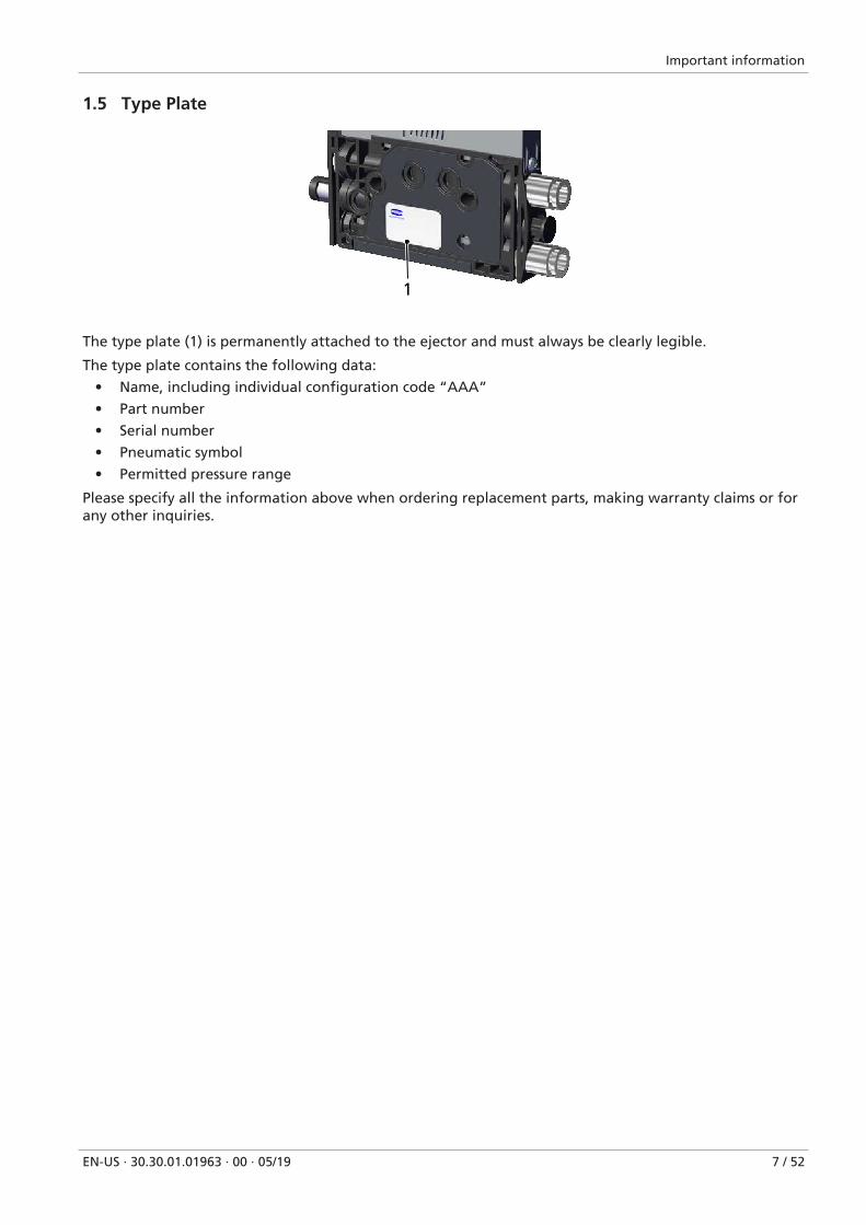
The type plate (1) is permanently attached to the ejector and must always be clearly legible.
The type plate contains the following data:
• Name, including individual configuration code “AAA”
• Part number
• Serial number
• Pneumatic symbol
• Permitted pressure range
Please specify all the information above when ordering replacement parts, making warranty claims or forany other inquiries.
Fundamental Safety Instructions
8 / 52 EN-US · 30.30.01.01963 · 00 · 05/19
2 Fundamental Safety Instructions
2.1 EmissionsThe ejector emits noise due to its use of compressed air.
WARNINGNoise pollution due to the escape of compressed air
Hearing damage!
4 Wear ear protectors.
4 The ejector must only be operated with a silencer.
2.2 Intended UseThe ejector is built in accordance with the latest standards of technology and is safe to operate upon de-livery; however, hazards can still arise during use.
The ejector is designed to generate a vacuum for gripping and transporting objects when used in conjunc-tion with suction cups. It is operated by a controller via discrete signals.
Neutral gases are approved as evacuation media. Neutral gases include air, nitrogen and inert gases (e.g.argon, xenon and neon).
The product is intended for industrial use.
Intended use includes observing the technical data and the installation and operating instructions in thismanual.
2.3 Non-Intended Use
WARNINGExtraction of hazardous media, liquids or bulk material
Personal injury or damage to property!
4 Do not extract harmful media such as dust, oil mists, vapors, aerosols etc.
4 Do not extract aggressive gases or media such as acids, acid fumes, bases, biocides, dis-infectants or detergents.
4 Do not extract liquids or bulk materials, e.g. granulates.
Schmalz accepts no liability for damages caused by non-intended usage of the ejector. In particular, thefollowing are considered non-intended use:
• Use in potentially explosive atmospheres
• Use in medical applications
• Lifting people or animals
• Evacuation of objects that are in danger of imploding
Fundamental Safety Instructions
EN-US · 30.30.01.01963 · 00 · 05/19 9 / 52
2.4 Personnel QualificationUnqualified personnel cannot recognize dangers and are therefore exposed to higher risks!
1. Task only qualified personnel to perform the tasks described in this operating instructions.
2. The product must be operated only by persons who have undergone appropriate training.
This operating instructions is intended for fitters who are trained in handling the product and who canoperate and install it.
2.5 Modifications to the EjectorSchmalz assumes no liability for consequences of modifications over which it has no control:
1. The ejector must be operated only in its original condition as delivered.
2. Use only original spare parts from Schmalz.
3. The ejector must be operated only in perfect condition.
Product description
10 / 52 EN-US · 30.30.01.01963 · 00 · 05/19
3 Product description
3.1 Description of the Ejector
3.1.1 Suction of the Workpiece (Vacuum Generation)
The ejector is designed for vacuum handling of airtight parts in combination with suction systems. Thevacuum is generated in a nozzle according to the Venturi principle, i.e. by using suction generated by theflow of accelerated compressed air. Compressed air is channeled into the ejector and flows through thenozzle. A vacuum is generated immediately downstream of the motive nozzle; this causes the air to besucked through the vacuum connection. The air and compressed air that have been removed by the suc-tion exit together via the silencer.
The venturi nozzle on the ejector is activated and deactivated using the suction command:
• In the NO (normally open) variant, the venturi nozzle is deactivated when the suction signal is re-ceived.
• In the NC (normally closed) variant, the venturi nozzle is activated when the suction signal is re-ceived.
An integrated sensor records the vacuum generated by the venturi nozzle. The exact vacuum value isshown on the display.
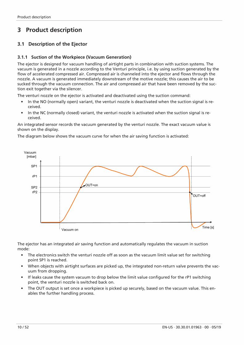
The diagram below shows the vacuum curve for when the air saving function is activated:
Vacuum[mbar]
Vacuum onTime [s]
SP1
SP2
rP1
rP2
OUT=on
OUT=off
The ejector has an integrated air saving function and automatically regulates the vacuum in suctionmode:
• The electronics switch the venturi nozzle off as soon as the vacuum limit value set for switchingpoint SP1 is reached.
• When objects with airtight surfaces are picked up, the integrated non-return valve prevents the vac-uum from dropping.
• If leaks cause the system vacuum to drop below the limit value configured for the rP1 switchingpoint, the venturi nozzle is switched back on.
• The OUT output is set once a workpiece is picked up securely, based on the vacuum value. This en-ables the further handling process.
Product description
EN-US · 30.30.01.01963 · 00 · 05/19 11 / 52
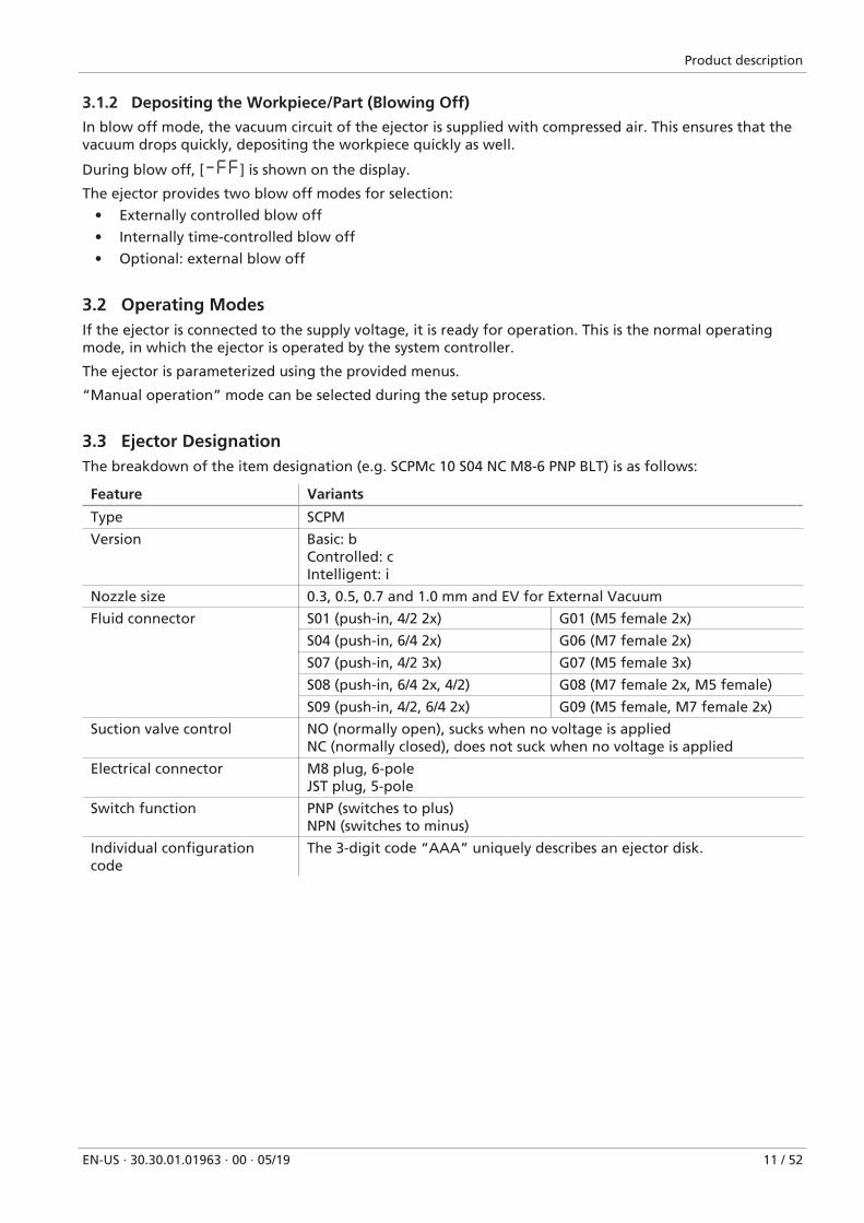
3.1.2 Depositing the Workpiece/Part (Blowing Off)
In blow off mode, the vacuum circuit of the ejector is supplied with compressed air. This ensures that thevacuum drops quickly, depositing the workpiece quickly as well.
During blow off, [-FF] is shown on the display.
The ejector provides two blow off modes for selection:
• Externally controlled blow off
• Internally time-controlled blow off
• Optional: external blow off
3.2 Operating ModesIf the ejector is connected to the supply voltage, it is ready for operation. This is the normal operatingmode, in which the ejector is operated by the system controller.
The ejector is parameterized using the provided menus.
“Manual operation” mode can be selected during the setup process.
3.3 Ejector DesignationThe breakdown of the item designation (e.g. SCPMc 10 S04 NC M8-6 PNP BLT) is as follows:
Feature Variants
Type SCPM
Version Basic: bControlled: cIntelligent: i
Nozzle size 0.3, 0.5, 0.7 and 1.0 mm and EV for External Vacuum
Fluid connector S01 (push-in, 4/2 2x) G01 (M5 female 2x)
S04 (push-in, 6/4 2x) G06 (M7 female 2x)
S07 (push-in, 4/2 3x) G07 (M5 female 3x)
S08 (push-in, 6/4 2x, 4/2) G08 (M7 female 2x, M5 female)
S09 (push-in, 4/2, 6/4 2x) G09 (M5 female, M7 female 2x)
Suction valve control NO (normally open), sucks when no voltage is appliedNC (normally closed), does not suck when no voltage is applied
Electrical connector M8 plug, 6-poleJST plug, 5-pole
Switch function PNP (switches to plus)NPN (switches to minus)
Individual configurationcode
The 3-digit code “AAA” uniquely describes an ejector disk.
Product description
12 / 52 EN-US · 30.30.01.01963 · 00 · 05/19
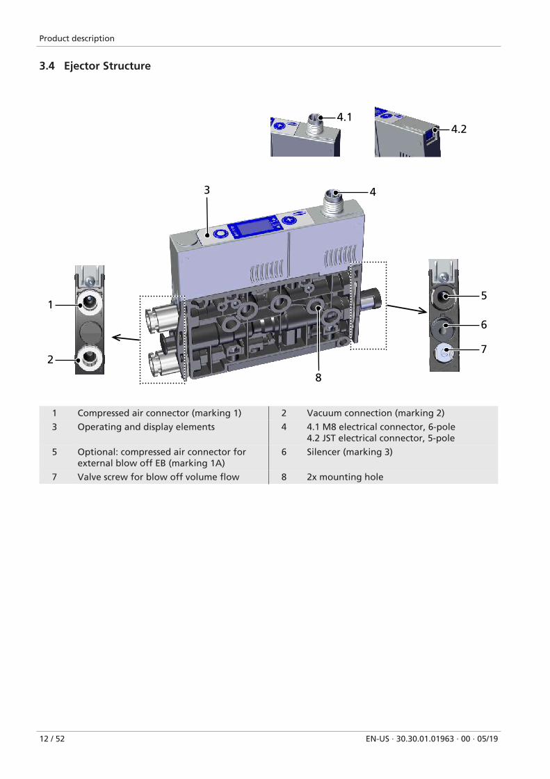
3.4 Ejector Structure
8
1
2
3 4
6
7
5
4.14.2
1 Compressed air connector (marking 1) 2 Vacuum connection (marking 2)
3 Operating and display elements 4 4.1 M8 electrical connector, 6-pole4.2 JST electrical connector, 5-pole
5 Optional: compressed air connector forexternal blow off EB (marking 1A)
6 Silencer (marking 3)
7 Valve screw for blow off volume flow 8 2x mounting hole
Product description
EN-US · 30.30.01.01963 · 00 · 05/19 13 / 52
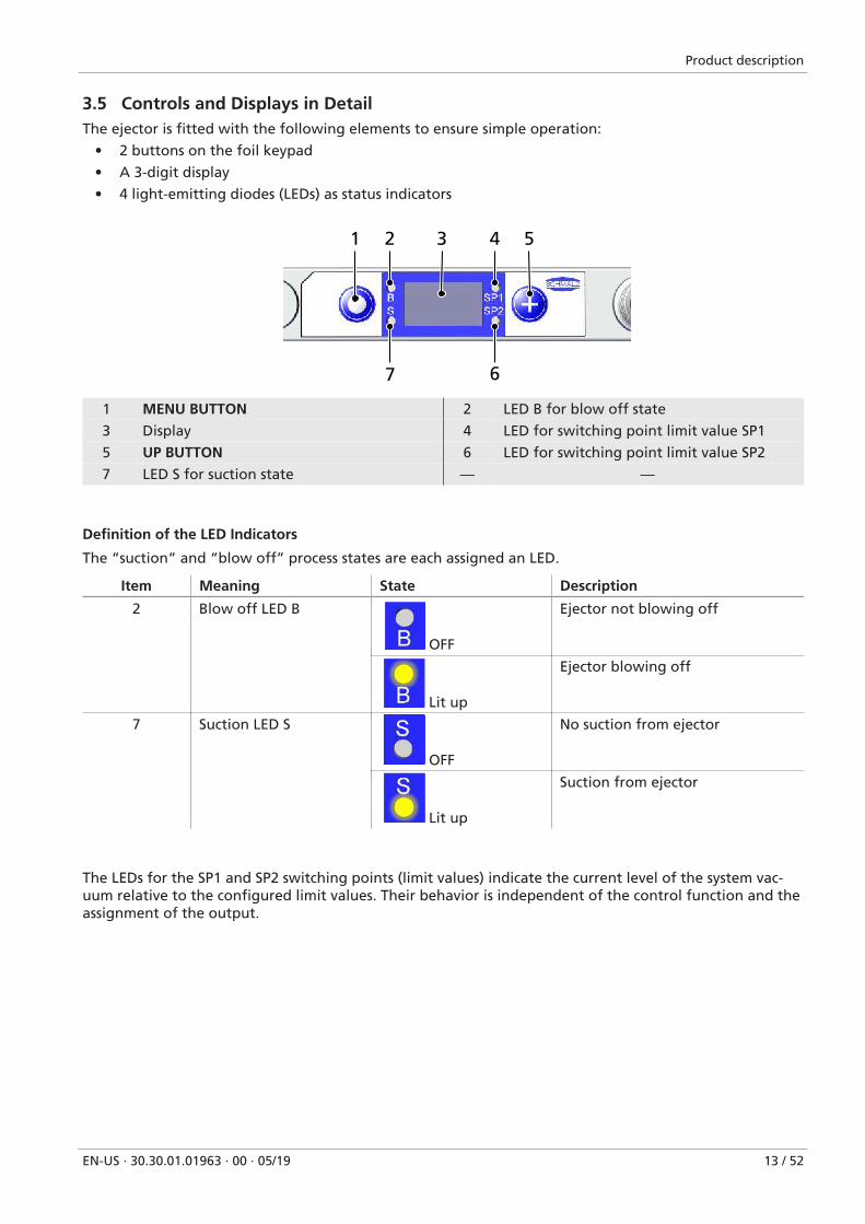
3.5 Controls and Displays in DetailThe ejector is fitted with the following elements to ensure simple operation:
• 2 buttons on the foil keypad
• A 3-digit display
• 4 light-emitting diodes (LEDs) as status indicators
1 2 3 4 5
7 6
1 MENU BUTTON 2 LED B for blow off state
3 Display 4 LED for switching point limit value SP1
5 UP BUTTON 6 LED for switching point limit value SP2
7 LED S for suction state — —
Definition of the LED Indicators
The “suction” and “blow off” process states are each assigned an LED.
Item Meaning State Description
2 Blow off LED B
OFF
Ejector not blowing off
Lit up
Ejector blowing off
7 Suction LED S
OFF
No suction from ejector
Lit up
Suction from ejector
The LEDs for the SP1 and SP2 switching points (limit values) indicate the current level of the system vac-uum relative to the configured limit values. Their behavior is independent of the control function and theassignment of the output.
Product description
14 / 52 EN-US · 30.30.01.01963 · 00 · 05/19
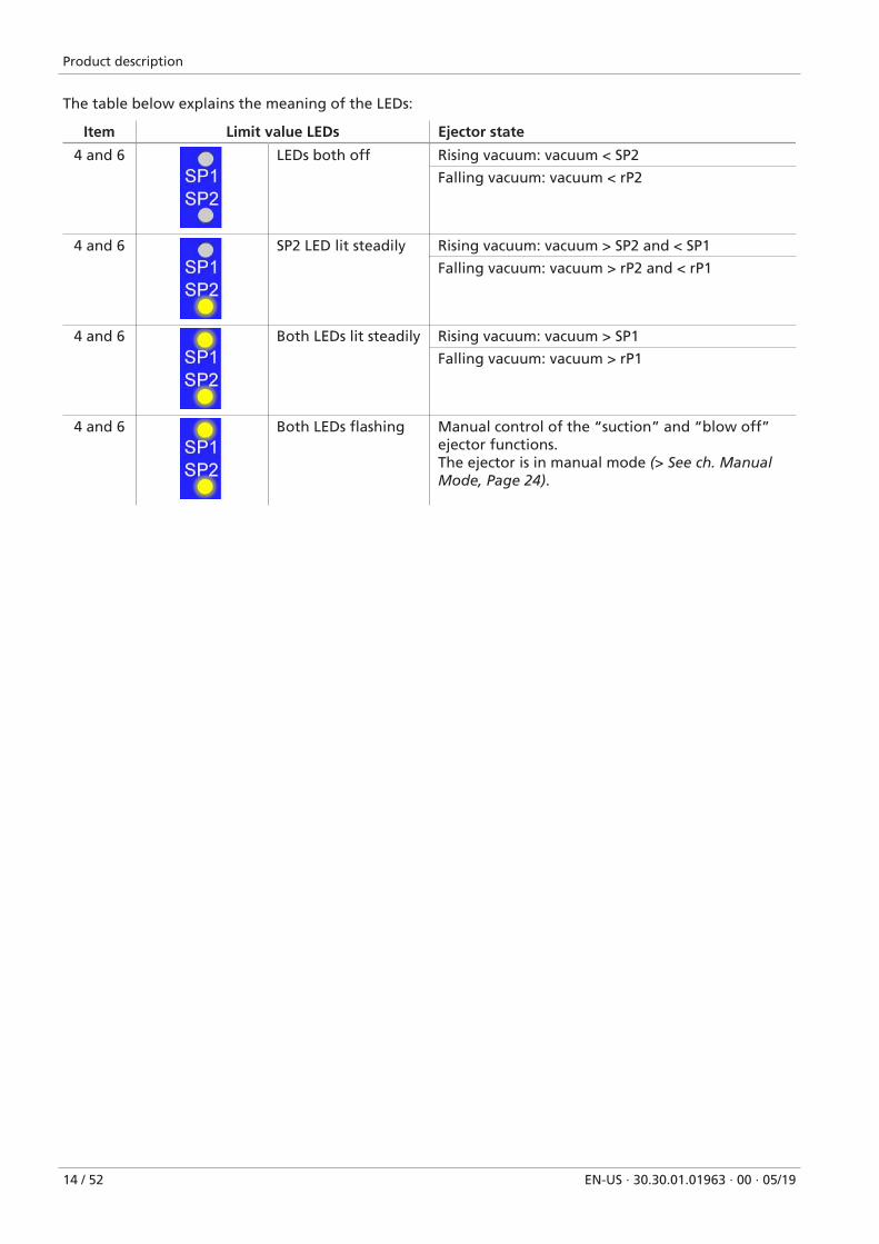
The table below explains the meaning of the LEDs:
Item Limit value LEDs Ejector state
4 and 6 LEDs both off Rising vacuum: vacuum < SP2
Falling vacuum: vacuum < rP2
4 and 6 SP2 LED lit steadily Rising vacuum: vacuum > SP2 and < SP1
Falling vacuum: vacuum > rP2 and < rP1
4 and 6 Both LEDs lit steadily Rising vacuum: vacuum > SP1
Falling vacuum: vacuum > rP1
4 and 6 Both LEDs flashing Manual control of the “suction” and “blow off”ejector functions.The ejector is in manual mode (> See ch. ManualMode, Page 24).
Technical Data
EN-US · 30.30.01.01963 · 00 · 05/19 15 / 52
4 Technical Data
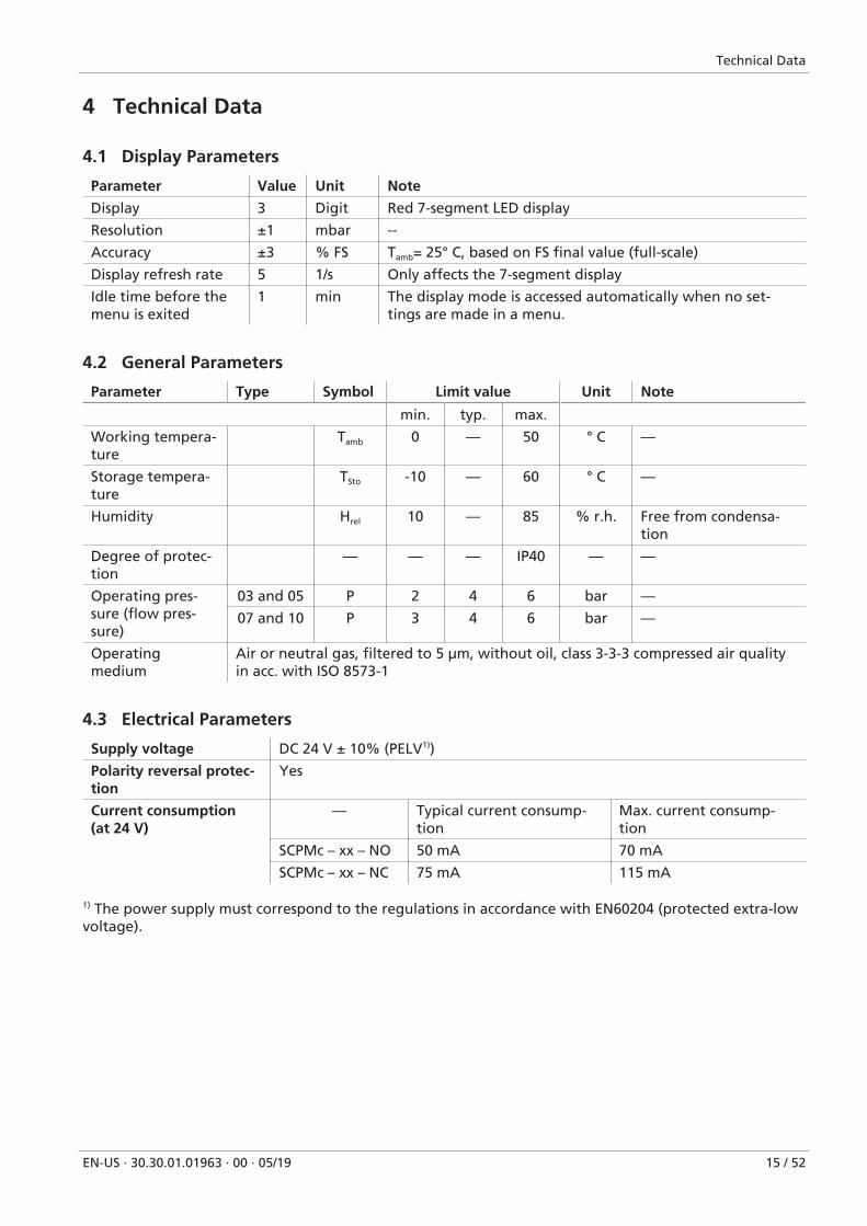
4.1 Display Parameters
Parameter Value Unit Note
Display 3 Digit Red 7-segment LED display
Resolution ±1 mbar --
Accuracy ±3 % FS Tamb= 25° C, based on FS final value (full-scale)
Display refresh rate 5 1/s Only affects the 7-segment display
Idle time before themenu is exited
1 min The display mode is accessed automatically when no set-tings are made in a menu.
4.2 General Parameters
Parameter Type Symbol Limit value Unit Note
min. typ. max.
Working tempera-ture
Tamb 0 — 50 ° C —
Storage tempera-ture
TSto -10 — 60 ° C —
Humidity Hrel 10 — 85 % r.h. Free from condensa-tion
Degree of protec-tion
— — — IP40 — —
Operating pres-sure (flow pres-sure)
03 and 05 P 2 4 6 bar —
07 and 10 P 3 4 6 bar —
Operatingmedium
Air or neutral gas, filtered to 5 µm, without oil, class 3-3-3 compressed air qualityin acc. with ISO 8573-1
4.3 Electrical Parameters
Supply voltage DC 24 V ± 10% (PELV1))
Polarity reversal protec-tion
Yes
Current consumption(at 24 V)
— Typical current consump-tion
Max. current consump-tion
SCPMc – xx – NO 50 mA 70 mA
SCPMc – xx – NC 75 mA 115 mA
1) The power supply must correspond to the regulations in accordance with EN60204 (protected extra-lowvoltage).
Technical Data
16 / 52 EN-US · 30.30.01.01963 · 00 · 05/19
4.4 Mechanical Data
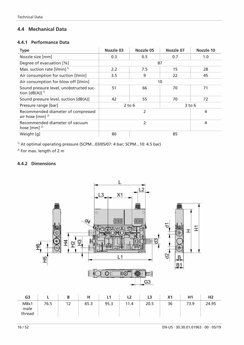
4.4.1 Performance Data
Type Nozzle 03 Nozzle 05 Nozzle 07 Nozzle 10
Nozzle size [mm] 0.3 0.5 0.7 1.0
Degree of evacuation [%] 87
Max. suction rate [l/min] 1) 2.2 7.5 15 28
Air consumption for suction [l/min] 3.5 9 22 45
Air consumption for blow off [l/min] 10
Sound pressure level, unobstructed suc-tion [dB(A)] 1)
51 66 70 71
Sound pressure level, suction [dB(A)] 42 55 70 72
Pressure range [bar] 2 to 6 3 to 6
Recommended diameter of compressedair hose [mm] 2)
2 4
Recommended diameter of vacuumhose [mm] 2)
2 4
Weight [g] 80 85
1) At optimal operating pressure (SCPM...03/05/07: 4 bar; SCPM...10: 4.5 bar)2) For max. length of 2 m
4.4.2 Dimensions
G3 L B H L1 L2 L3 X1 H1 H2
M8x1male
thread
76.5 12 65.3 95.3 11.4 20.5 36 73.9 24.95
Technical Data
EN-US · 30.30.01.01963 · 00 · 05/19 17 / 52
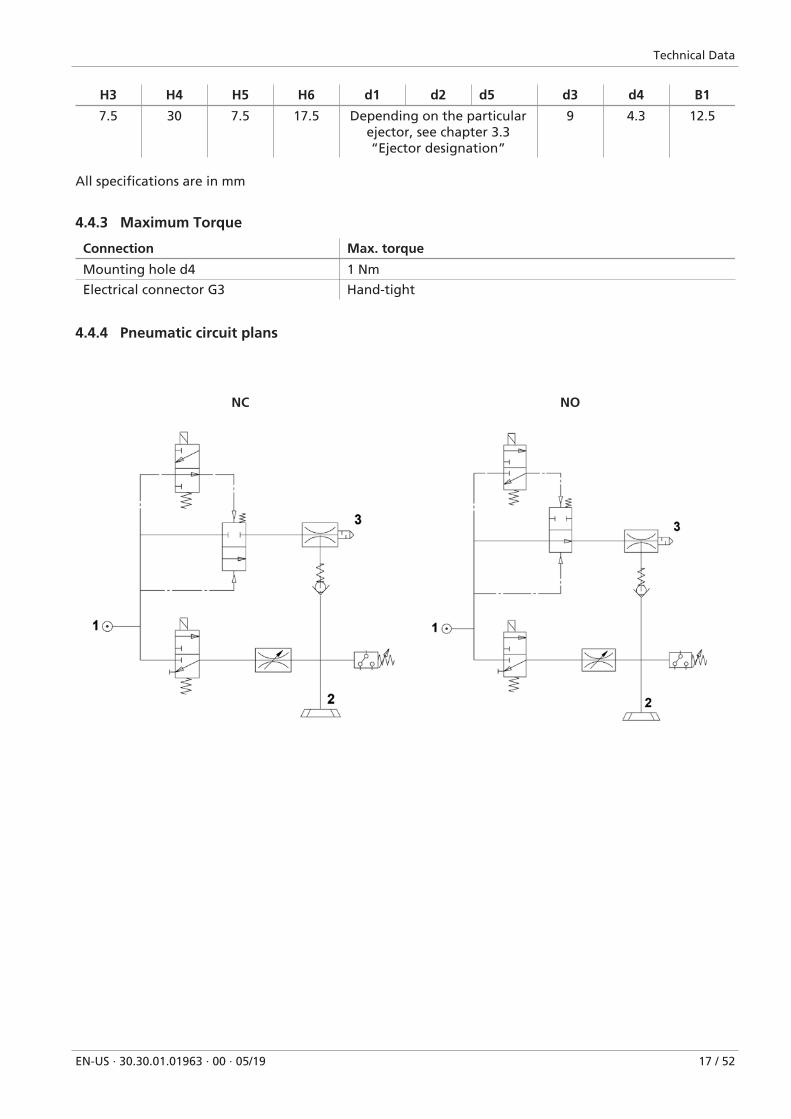
H3 H4 H5 H6 d1 d2 d5 d3 d4 B1
7.5 30 7.5 17.5 Depending on the particularejector, see chapter 3.3“Ejector designation”
9 4.3 12.5
All specifications are in mm
4.4.3 Maximum Torque
Connection Max. torque
Mounting hole d4 1 Nm
Electrical connector G3 Hand-tight
4.4.4 Pneumatic circuit plans
NC NO
Technical Data
18 / 52 EN-US · 30.30.01.01963 · 00 · 05/19
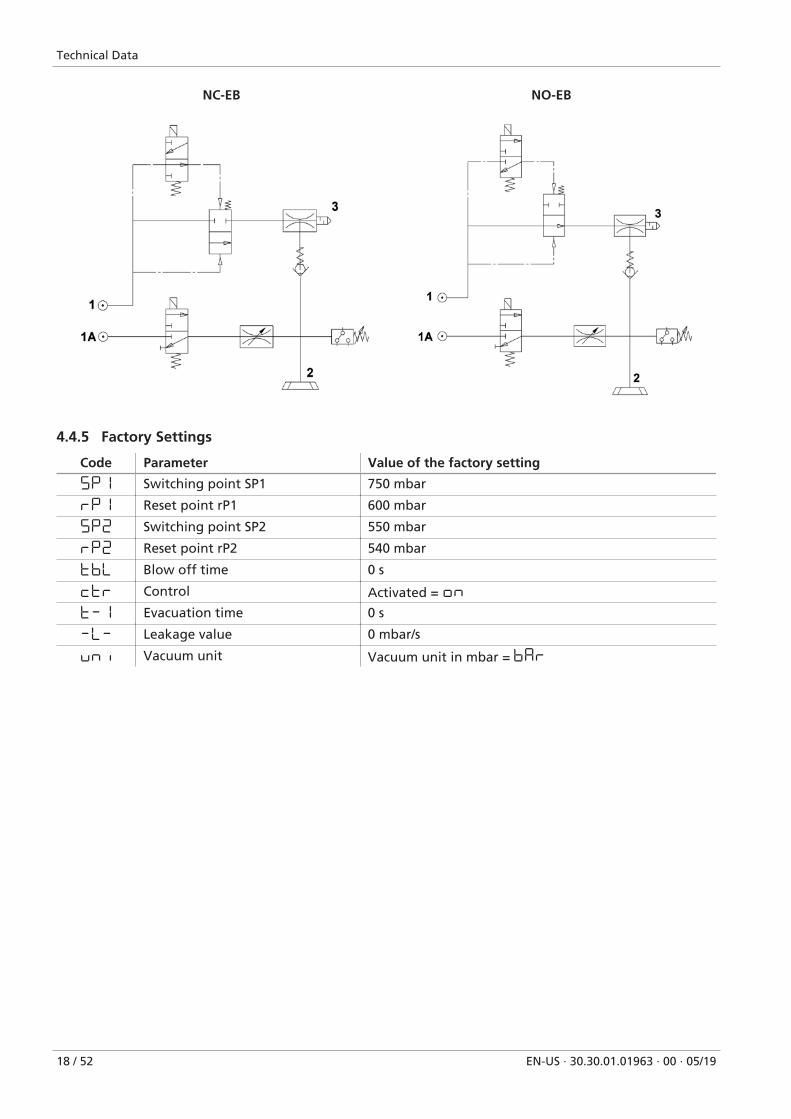
NC-EB NO-EB
4.4.5 Factory Settings
Code Parameter Value of the factory setting
5P1 Switching point SP1 750 mbar
rP1 Reset point rP1 600 mbar
5P2 Switching point SP2 550 mbar
rP2 Reset point rP2 540 mbar
tbL Blow off time 0 s
ctr Control Activated = on
t-1 Evacuation time 0 s
-L- Leakage value 0 mbar/s
uni Vacuum unit Vacuum unit in mbar = bar
Operating and Menu Concepts
EN-US · 30.30.01.01963 · 00 · 05/19 19 / 52
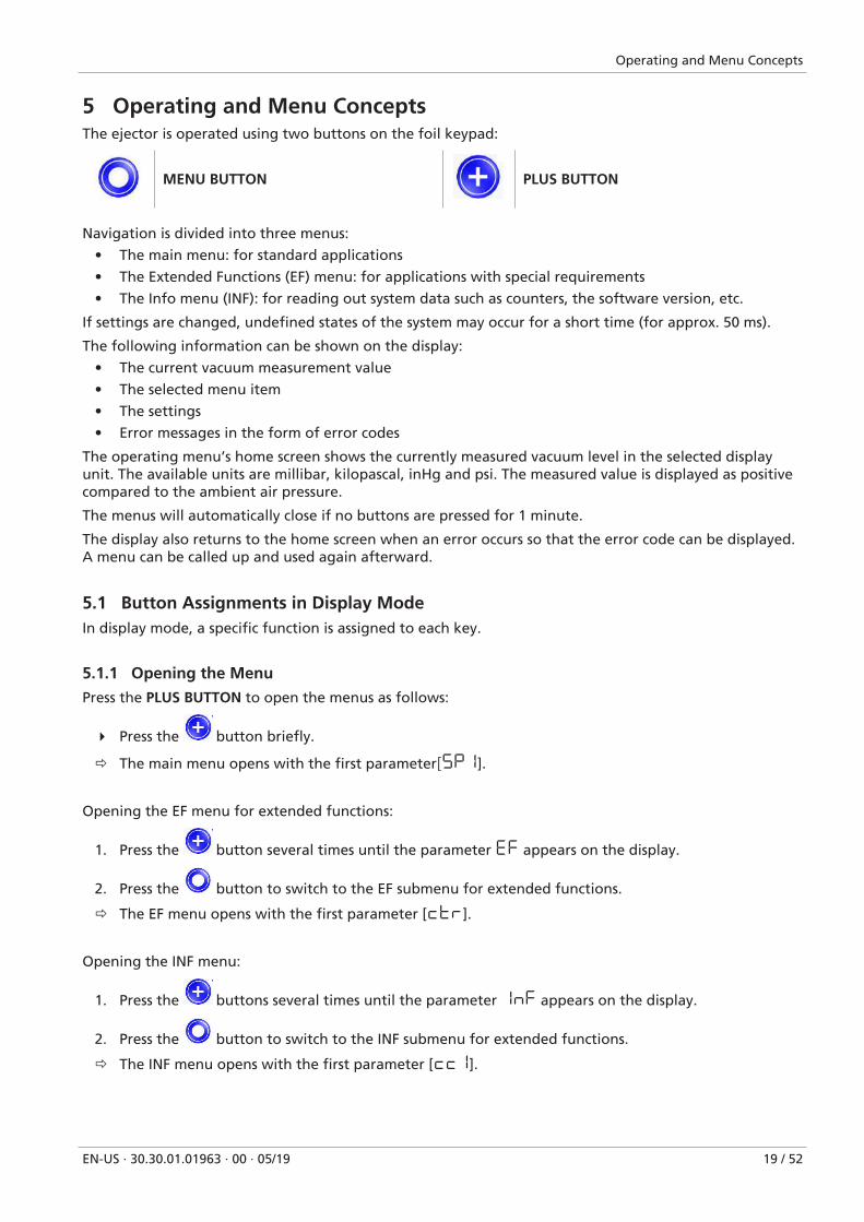
5 Operating and Menu ConceptsThe ejector is operated using two buttons on the foil keypad:
MENU BUTTON PLUS BUTTON
Navigation is divided into three menus:
• The main menu: for standard applications
• The Extended Functions (EF) menu: for applications with special requirements
• The Info menu (INF): for reading out system data such as counters, the software version, etc.
If settings are changed, undefined states of the system may occur for a short time (for approx. 50 ms).
The following information can be shown on the display:
• The current vacuum measurement value
• The selected menu item
• The settings
• Error messages in the form of error codes
The operating menu’s home screen shows the currently measured vacuum level in the selected displayunit. The available units are millibar, kilopascal, inHg and psi. The measured value is displayed as positivecompared to the ambient air pressure.
The menus will automatically close if no buttons are pressed for 1 minute.
The display also returns to the home screen when an error occurs so that the error code can be displayed.A menu can be called up and used again afterward.
5.1 Button Assignments in Display ModeIn display mode, a specific function is assigned to each key.
5.1.1 Opening the Menu
Press the PLUS BUTTON to open the menus as follows:
4 Press the button briefly.
ð The main menu opens with the first parameter[5P1].
Opening the EF menu for extended functions:
1. Press the button several times until the parameter EF appears on the display.
2. Press the button to switch to the EF submenu for extended functions.
ð The EF menu opens with the first parameter [ctr].
Opening the INF menu:
1. Press the buttons several times until the parameter 1nF appears on the display.
2. Press the button to switch to the INF submenu for extended functions.
ð The INF menu opens with the first parameter [cc1].
Operating and Menu Concepts
20 / 52 EN-US · 30.30.01.01963 · 00 · 05/19
5.1.2 Displaying the basic settings (slide show)
When you press the button from the home screen, the following parameters are automatically dis-played one after the other on the display (slide show):
• The vacuum unit
• The value of the switching point SP1
• The value of reset point rP1
• The value of switching point SP2
• The supply voltage US
The display cycle returns to the vacuum display after a complete cycle or can be canceled at any time bypressing any button.
5.2 Main MenuAll settings for standard applications can be accessed and configured using the main menu.
5.2.1 Functions in the Main Menu
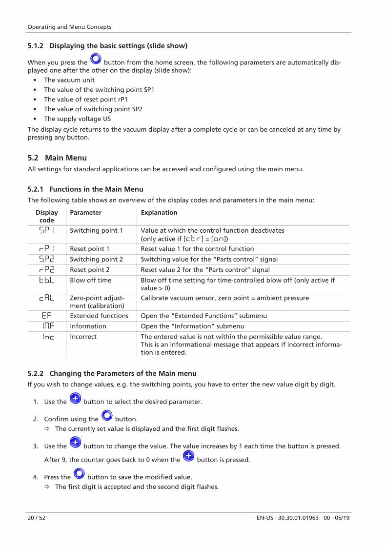
The following table shows an overview of the display codes and parameters in the main menu:
Displaycode
Parameter Explanation
5P1 Switching point 1 Value at which the control function deactivates(only active if [ctr] = [on])
rP1 Reset point 1 Reset value 1 for the control function
5P2 Switching point 2 Switching value for the “Parts control” signal
rP2 Reset point 2 Reset value 2 for the “Parts control” signal
tbL Blow off time Blow off time setting for time-controlled blow off (only active ifvalue > 0)
CAL Zero-point adjust-ment (calibration)
Calibrate vacuum sensor, zero point = ambient pressure
EF Extended functions Open the “Extended Functions” submenu
1mF Information Open the “Information” submenu
1nc Incorrect The entered value is not within the permissible value range.This is an informational message that appears if incorrect informa-tion is entered.
5.2.2 Changing the Parameters of the Main menu
If you wish to change values, e.g. the switching points, you have to enter the new value digit by digit.
1. Use the button to select the desired parameter.
2. Confirm using the button.
ð The currently set value is displayed and the first digit flashes.
3. Use the button to change the value. The value increases by 1 each time the button is pressed.
After 9, the counter goes back to 0 when the button is pressed.
4. Press the button to save the modified value.
ð The first digit is accepted and the second digit flashes.
Operating and Menu Concepts
EN-US · 30.30.01.01963 · 00 · 05/19 21 / 52
5. Use the button to set the second digit.
6. Press the button to save the modified value.
ð The second digit is accepted and the third digit flashes.
7. Use the button to set the third digit.
8. Press the button to save the modified value.
ð If the value entered lies within the permissible value range, it is accepted and the modified parame-ter is displayed.
ð If the entered value does not lie within the permissible value range, this is briefly indicated on thedisplay [1nc] and the new value is not accepted.
If input is interrupted for longer than 1 minute or if no input is made, the display automatically switchesto the measurement display.
5.3 Extended Functions menu (EF)An “Extended Functions” menu (EF) is available for applications with special requirements.
5.3.1 Functions in the Extended Functions menu (EF)
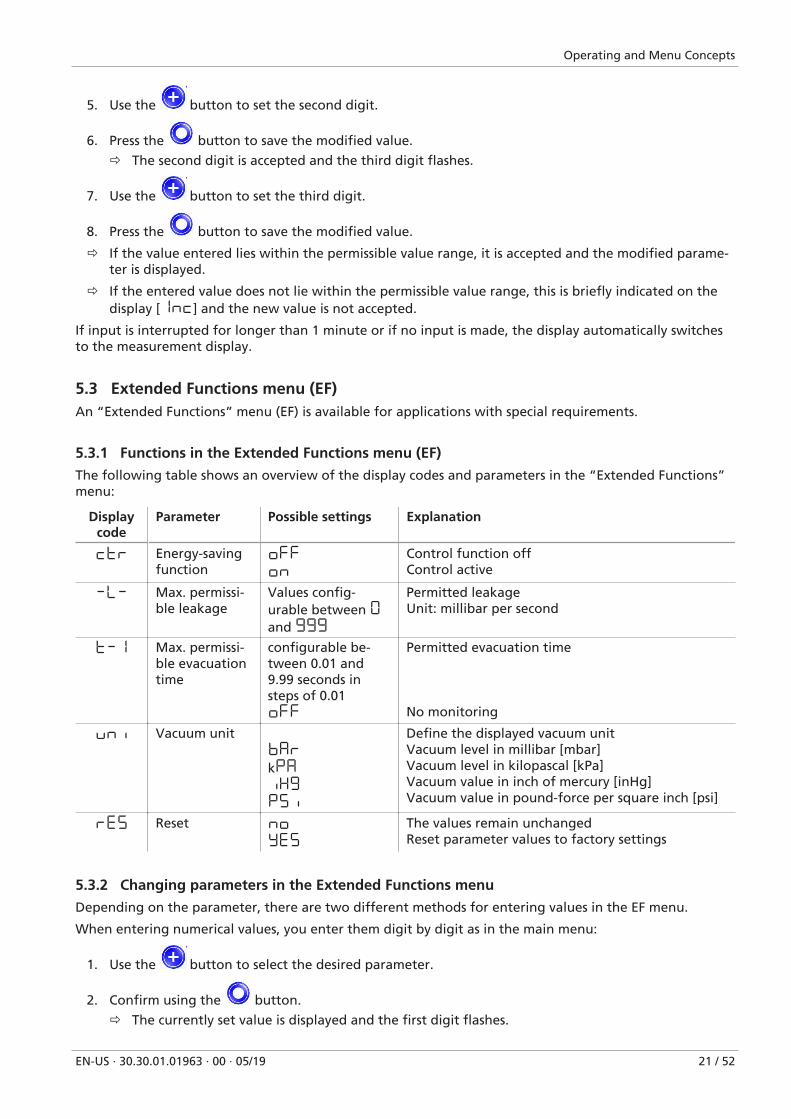
The following table shows an overview of the display codes and parameters in the “Extended Functions”menu:
Displaycode
Parameter Possible settings Explanation
ctr Energy-savingfunction
oFF
on
Control function offControl active
-L- Max. permissi-ble leakage
Values config-urable between 0and 999
Permitted leakageUnit: millibar per second
t-1 Max. permissi-ble evacuationtime
configurable be-tween 0.01 and9.99 seconds insteps of 0.01off
Permitted evacuation time
No monitoring
uni Vacuum unitbAr
kPA
iX9
P5i
Define the displayed vacuum unitVacuum level in millibar [mbar]Vacuum level in kilopascal [kPa]Vacuum value in inch of mercury [inHg]Vacuum value in pound-force per square inch [psi]
rE5 Reset No
YE5
The values remain unchangedReset parameter values to factory settings
5.3.2 Changing parameters in the Extended Functions menu
Depending on the parameter, there are two different methods for entering values in the EF menu.
When entering numerical values, you enter them digit by digit as in the main menu:
1. Use the button to select the desired parameter.
2. Confirm using the button.
ð The currently set value is displayed and the first digit flashes.
Operating and Menu Concepts
22 / 52 EN-US · 30.30.01.01963 · 00 · 05/19
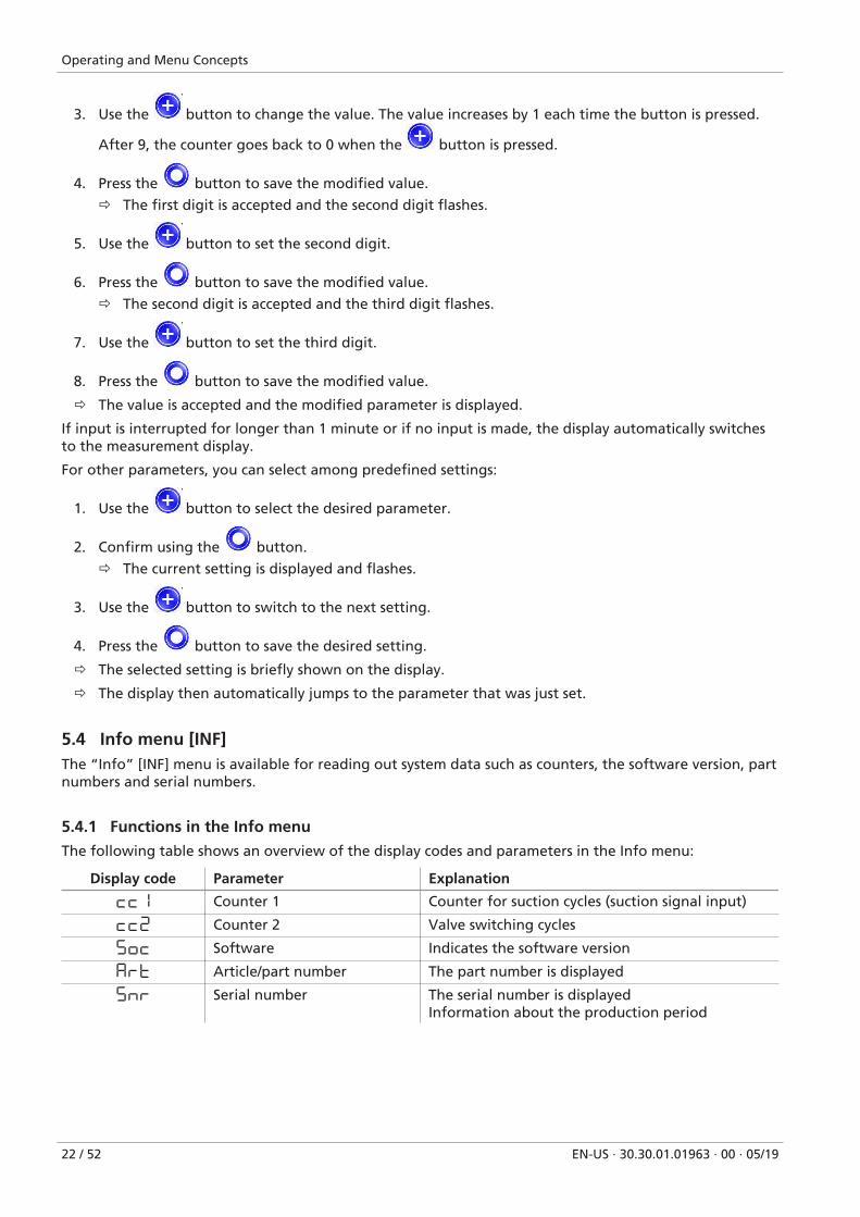
3. Use the button to change the value. The value increases by 1 each time the button is pressed.
After 9, the counter goes back to 0 when the button is pressed.
4. Press the button to save the modified value.
ð The first digit is accepted and the second digit flashes.
5. Use the button to set the second digit.
6. Press the button to save the modified value.
ð The second digit is accepted and the third digit flashes.
7. Use the button to set the third digit.
8. Press the button to save the modified value.
ð The value is accepted and the modified parameter is displayed.
If input is interrupted for longer than 1 minute or if no input is made, the display automatically switchesto the measurement display.
For other parameters, you can select among predefined settings:
1. Use the button to select the desired parameter.
2. Confirm using the button.
ð The current setting is displayed and flashes.
3. Use the button to switch to the next setting.
4. Press the button to save the desired setting.
ð The selected setting is briefly shown on the display.
ð The display then automatically jumps to the parameter that was just set.
5.4 Info menu [INF]The “Info” [INF] menu is available for reading out system data such as counters, the software version, partnumbers and serial numbers.
5.4.1 Functions in the Info menu
The following table shows an overview of the display codes and parameters in the Info menu:
Display code Parameter Explanation
cc1 Counter 1 Counter for suction cycles (suction signal input)
cc2 Counter 2 Valve switching cycles
5oC Software Indicates the software version
Art Article/part number The part number is displayed
5nr Serial number The serial number is displayedInformation about the production period
Operating and Menu Concepts
EN-US · 30.30.01.01963 · 00 · 05/19 23 / 52
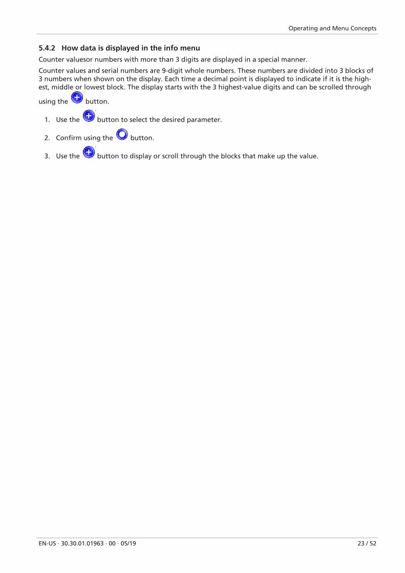
5.4.2 How data is displayed in the info menu
Counter valuesor numbers with more than 3 digits are displayed in a special manner.
Counter values and serial numbers are 9-digit whole numbers. These numbers are divided into 3 blocks of3 numbers when shown on the display. Each time a decimal point is displayed to indicate if it is the high-est, middle or lowest block. The display starts with the 3 highest-value digits and can be scrolled through
using the button.
1. Use the button to select the desired parameter.
2. Confirm using the button.
3. Use the button to display or scroll through the blocks that make up the value.
Description of Functions
24 / 52 EN-US · 30.30.01.01963 · 00 · 05/19
6 Description of Functions
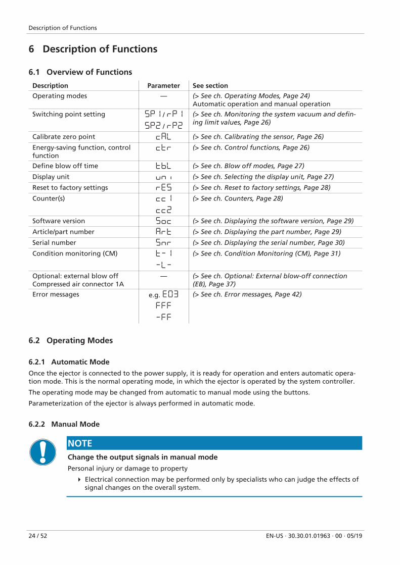
6.1 Overview of Functions
Description Parameter See section
Operating modes — (> See ch. Operating Modes, Page 24)Automatic operation and manual operation
Switching point setting 5P1 / rP1
5P2 / rP2
(> See ch. Monitoring the system vacuum and defin-ing limit values, Page 26)
Calibrate zero point CAL (> See ch. Calibrating the sensor, Page 26)
Energy-saving function, controlfunction
ctr (> See ch. Control functions, Page 26)
Define blow off time tbL (> See ch. Blow off modes, Page 27)
Display unit uni (> See ch. Selecting the display unit, Page 27)
Reset to factory settings rE5 (> See ch. Reset to factory settings, Page 28)
Counter(s) cc1
cc2
(> See ch. Counters, Page 28)
Software version 5oc (> See ch. Displaying the software version, Page 29)
Article/part number Art (> See ch. Displaying the part number, Page 29)
Serial number 5nr (> See ch. Displaying the serial number, Page 30)
Condition monitoring (CM) t-1
-L-
(> See ch. Condition Monitoring (CM), Page 31)
Optional: external blow offCompressed air connector 1A
— (> See ch. Optional: External blow-off connection(EB), Page 37)
Error messages e.g. E03
FFF
-FF
(> See ch. Error messages, Page 42)
6.2 Operating Modes
6.2.1 Automatic Mode
Once the ejector is connected to the power supply, it is ready for operation and enters automatic opera-tion mode. This is the normal operating mode, in which the ejector is operated by the system controller.
The operating mode may be changed from automatic to manual mode using the buttons.
Parameterization of the ejector is always performed in automatic mode.
6.2.2 Manual Mode
NOTEChange the output signals in manual mode
Personal injury or damage to property
4 Electrical connection may be performed only by specialists who can judge the effects ofsignal changes on the overall system.
Description of Functions
EN-US · 30.30.01.01963 · 00 · 05/19 25 / 52
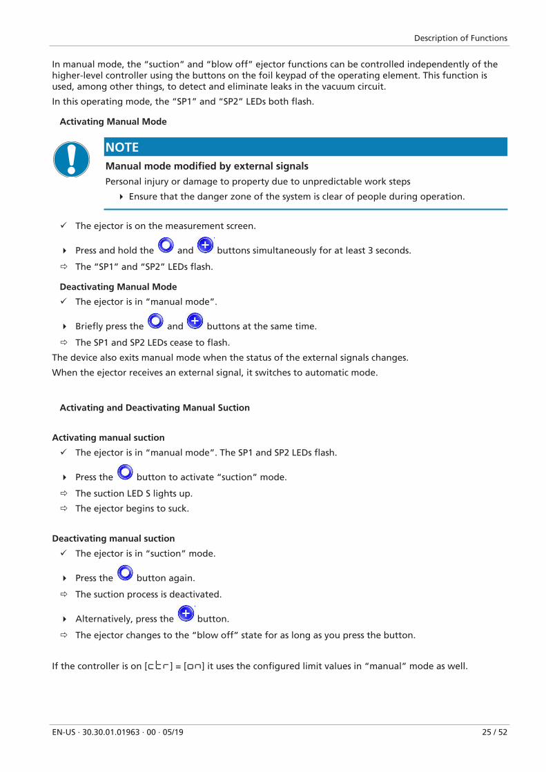
In manual mode, the “suction” and “blow off” ejector functions can be controlled independently of thehigher-level controller using the buttons on the foil keypad of the operating element. This function isused, among other things, to detect and eliminate leaks in the vacuum circuit.
In this operating mode, the “SP1” and “SP2” LEDs both flash.
Activating Manual Mode
NOTEManual mode modified by external signals
Personal injury or damage to property due to unpredictable work steps
4 Ensure that the danger zone of the system is clear of people during operation.
ü The ejector is on the measurement screen.
4 Press and hold the and buttons simultaneously for at least 3 seconds.
ð The “SP1” and “SP2” LEDs flash.
Deactivating Manual Mode
ü The ejector is in “manual mode”.
4 Briefly press the and buttons at the same time.
ð The SP1 and SP2 LEDs cease to flash.
The device also exits manual mode when the status of the external signals changes.
When the ejector receives an external signal, it switches to automatic mode.
Activating and Deactivating Manual Suction
Activating manual suction
ü The ejector is in “manual mode”. The SP1 and SP2 LEDs flash.
4 Press the button to activate “suction” mode.
ð The suction LED S lights up.
ð The ejector begins to suck.
Deactivating manual suction
ü The ejector is in “suction” mode.
4 Press the button again.
ð The suction process is deactivated.
4 Alternatively, press the button.
ð The ejector changes to the “blow off” state for as long as you press the button.
If the controller is on [ctr] = [on] it uses the configured limit values in “manual” mode as well.
Description of Functions
26 / 52 EN-US · 30.30.01.01963 · 00 · 05/19
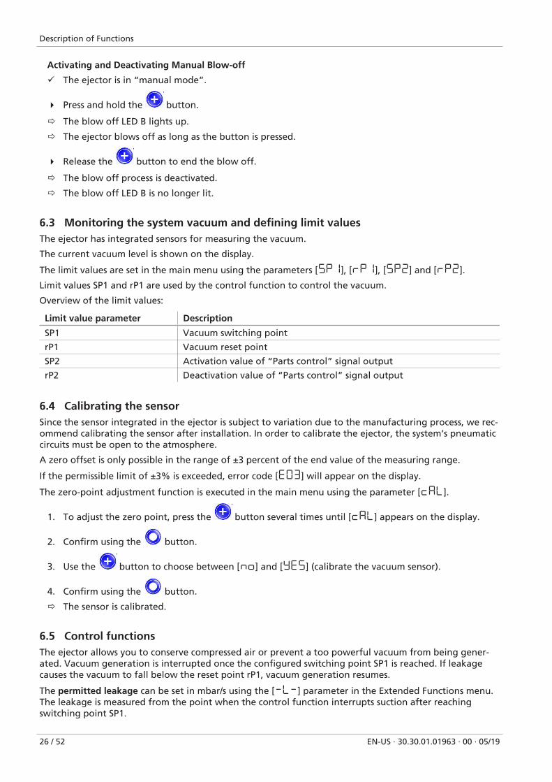
Activating and Deactivating Manual Blow-off
ü The ejector is in “manual mode”.
4 Press and hold the button.
ð The blow off LED B lights up.
ð The ejector blows off as long as the button is pressed.
4 Release the button to end the blow off.
ð The blow off process is deactivated.
ð The blow off LED B is no longer lit.
6.3 Monitoring the system vacuum and defining limit valuesThe ejector has integrated sensors for measuring the vacuum.
The current vacuum level is shown on the display.
The limit values are set in the main menu using the parameters [5P1], [rP1], [5P2] and [rP2].
Limit values SP1 and rP1 are used by the control function to control the vacuum.
Overview of the limit values:
Limit value parameter Description
SP1 Vacuum switching point
rP1 Vacuum reset point
SP2 Activation value of “Parts control” signal output
rP2 Deactivation value of “Parts control” signal output
6.4 Calibrating the sensorSince the sensor integrated in the ejector is subject to variation due to the manufacturing process, we rec-ommend calibrating the sensor after installation. In order to calibrate the ejector, the system’s pneumaticcircuits must be open to the atmosphere.
A zero offset is only possible in the range of ±3 percent of the end value of the measuring range.
If the permissible limit of ±3% is exceeded, error code [E03] will appear on the display.
The zero-point adjustment function is executed in the main menu using the parameter [CAL].
1. To adjust the zero point, press the button several times until [CAL] appears on the display.
2. Confirm using the button.
3. Use the button to choose between [No] and [YE5] (calibrate the vacuum sensor).
4. Confirm using the button.
ð The sensor is calibrated.
6.5 Control functionsThe ejector allows you to conserve compressed air or prevent a too powerful vacuum from being gener-ated. Vacuum generation is interrupted once the configured switching point SP1 is reached. If leakagecauses the vacuum to fall below the reset point rP1, vacuum generation resumes.
The permitted leakage can be set in mbar/s using the [-L-] parameter in the Extended Functions menu.The leakage is measured from the point when the control function interrupts suction after reachingswitching point SP1.
Description of Functions
EN-US · 30.30.01.01963 · 00 · 05/19 27 / 52
The following operating modes can be set for the control function using the [ctr] parameter in the Ex-tended Functions menu.
6.5.1 No Control (Continuous Suction)
The ejector produces continuous suction with maximum power. This setting is recommended for very por-ous workpieces, which would otherwise cause the vacuum generator to switch on and off continuouslydue to the high rate of leakage.
For this mode, the control function is set to [ctr] = [off].
6.5.2 Control
The ejector switches off vacuum generation when the switching point SP1 is reached and switches it backon when the vacuum falls below the reset point rP1. The switching point evaluation for SP1 follows thecontrol function. This setting is particularly recommended for airtight workpieces.
For this mode, the control function is set to [ctr] = [on].
6.6 Blow off modesYou can choose between two blow off modes.
6.6.1 Externally Controlled Blow-Off
The “blow off” valve is controlled directly by the “blow off” command. The ejector switches to blow offmode for as long as the “blow off” signal is present.
The “blow off” signal is given priority over the “suction” signal.
6.6.2 Internally Time-Controlled Blow-Off
The function is activated by setting a blow off time using the [tbl] parameter in the main menu.
The “blow off” valve is automatically activated for the configured time period as soon as the ejectorleaves “suction” mode.
The “blow off” signal overrides the “suction” signal, even if the specified blow off time is very long.
6.6.3 Setting the blow off time
The blow off time can be set using the [tbL] parameter in the main menu.
The value displayed indicates the blow off time in seconds. The time can range from 0.01 to 9.99 seconds.
Set the time for time-controlled blow off (only active if value > 0). If you set the value to 0, the ejector isautomatically in “externally controlled blow off” mode.
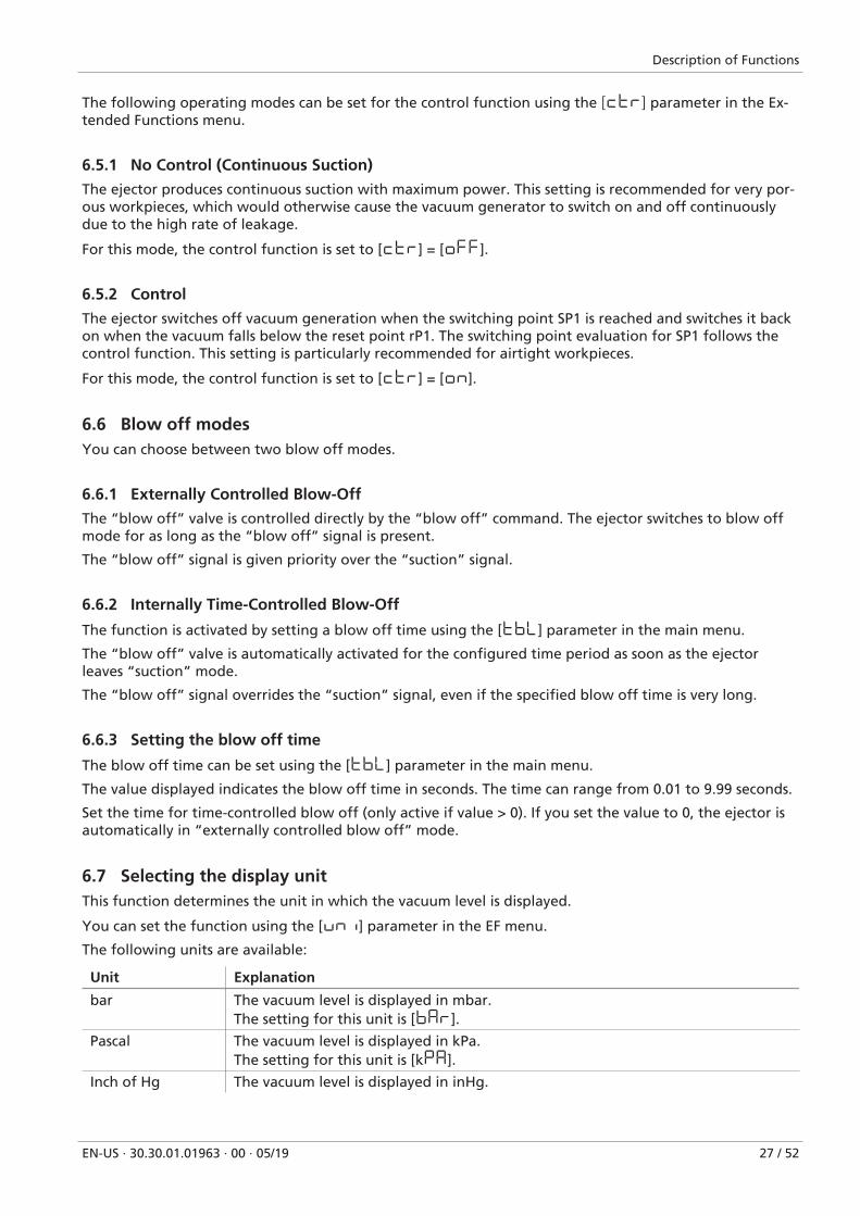
6.7 Selecting the display unitThis function determines the unit in which the vacuum level is displayed.
You can set the function using the [uni] parameter in the EF menu.
The following units are available:
Unit Explanation
bar The vacuum level is displayed in mbar.The setting for this unit is [bAr].
Pascal The vacuum level is displayed in kPa.The setting for this unit is [kPA].
Inch of Hg The vacuum level is displayed in inHg.
Description of Functions
28 / 52 EN-US · 30.30.01.01963 · 00 · 05/19
Unit Explanation
The setting for this unit is [iX9].
psi The vacuum level is displayed in psi.The setting for this unit is [P5i].
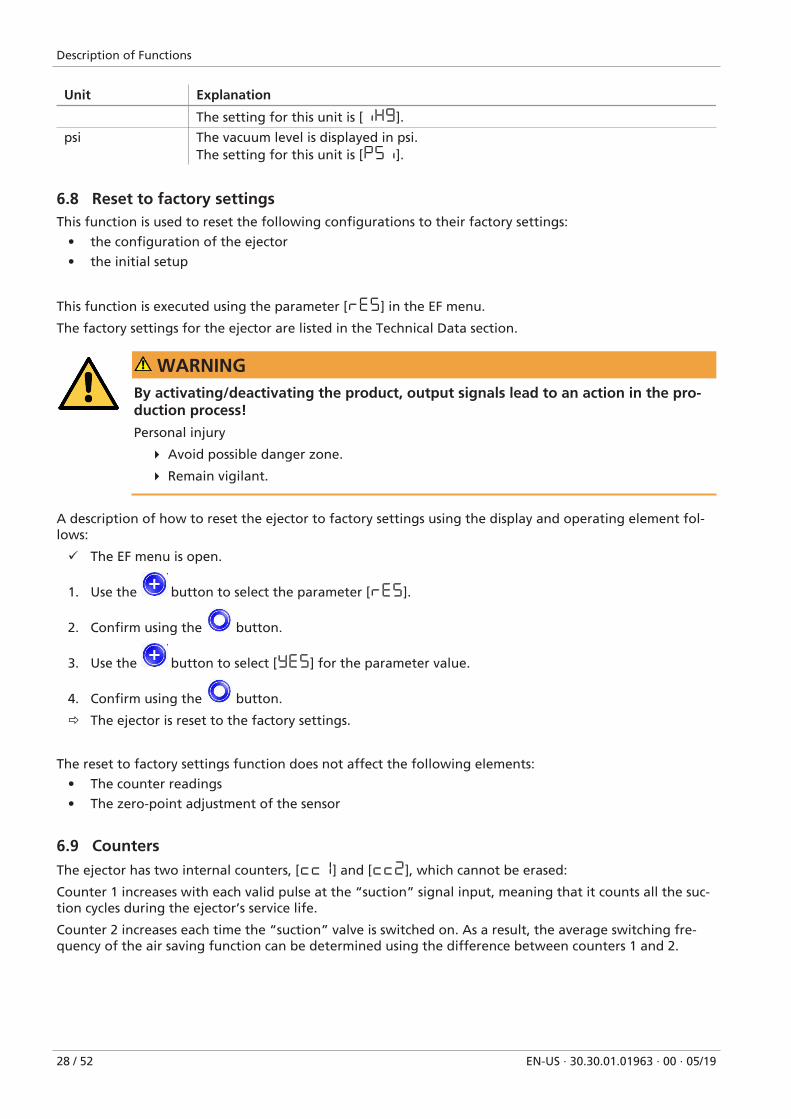
6.8 Reset to factory settingsThis function is used to reset the following configurations to their factory settings:
• the configuration of the ejector
• the initial setup
This function is executed using the parameter [rE5] in the EF menu.
The factory settings for the ejector are listed in the Technical Data section.
WARNINGBy activating/deactivating the product, output signals lead to an action in the pro-duction process!
Personal injury
4 Avoid possible danger zone.
4 Remain vigilant.
A description of how to reset the ejector to factory settings using the display and operating element fol-lows:
ü The EF menu is open.
1. Use the button to select the parameter [rE5].
2. Confirm using the button.
3. Use the button to select [YE5] for the parameter value.
4. Confirm using the button.
ð The ejector is reset to the factory settings.
The reset to factory settings function does not affect the following elements:
• The counter readings
• The zero-point adjustment of the sensor
6.9 CountersThe ejector has two internal counters, [cc1] and [cc2], which cannot be erased:
Counter 1 increases with each valid pulse at the “suction” signal input, meaning that it counts all the suc-tion cycles during the ejector’s service life.
Counter 2 increases each time the “suction” valve is switched on. As a result, the average switching fre-quency of the air saving function can be determined using the difference between counters 1 and 2.
Description of Functions
EN-US · 30.30.01.01963 · 00 · 05/19 29 / 52
Designation Display parameter Description
Counter 1 [Cc1] Counter for suction cycles (suction signal input)
Counter 2 [Cc2] Counter for the “suction valve” switching fre-quency
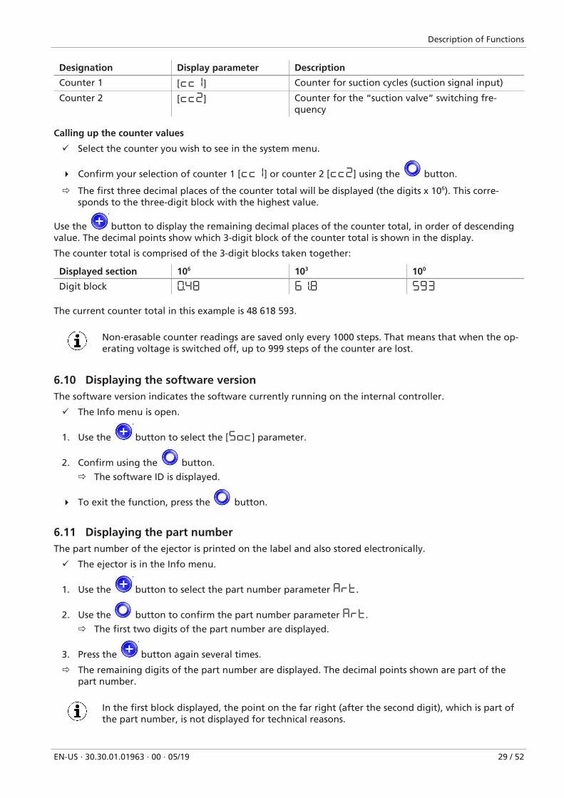
Calling up the counter values
ü Select the counter you wish to see in the system menu.
4 Confirm your selection of counter 1 [cc1] or counter 2 [cc2] using the button.
ð The first three decimal places of the counter total will be displayed (the digits x 106). This corre-sponds to the three-digit block with the highest value.
Use the button to display the remaining decimal places of the counter total, in order of descendingvalue. The decimal points show which 3-digit block of the counter total is shown in the display.
The counter total is comprised of the 3-digit blocks taken together:
Displayed section 106 103 100
Digit block 0.48 61.8 593
The current counter total in this example is 48 618 593.
Non-erasable counter readings are saved only every 1000 steps. That means that when the op-erating voltage is switched off, up to 999 steps of the counter are lost.
6.10 Displaying the software versionThe software version indicates the software currently running on the internal controller.
ü The Info menu is open.
1. Use the button to select the [5oc] parameter.
2. Confirm using the button.
ð The software ID is displayed.
4 To exit the function, press the button.
6.11 Displaying the part numberThe part number of the ejector is printed on the label and also stored electronically.
ü The ejector is in the Info menu.
1. Use the button to select the part number parameter Art.
2. Use the button to confirm the part number parameter Art.
ð The first two digits of the part number are displayed.
3. Press the button again several times.
ð The remaining digits of the part number are displayed. The decimal points shown are part of thepart number.
In the first block displayed, the point on the far right (after the second digit), which is part ofthe part number, is not displayed for technical reasons.
Description of Functions
30 / 52 EN-US · 30.30.01.01963 · 00 · 05/19
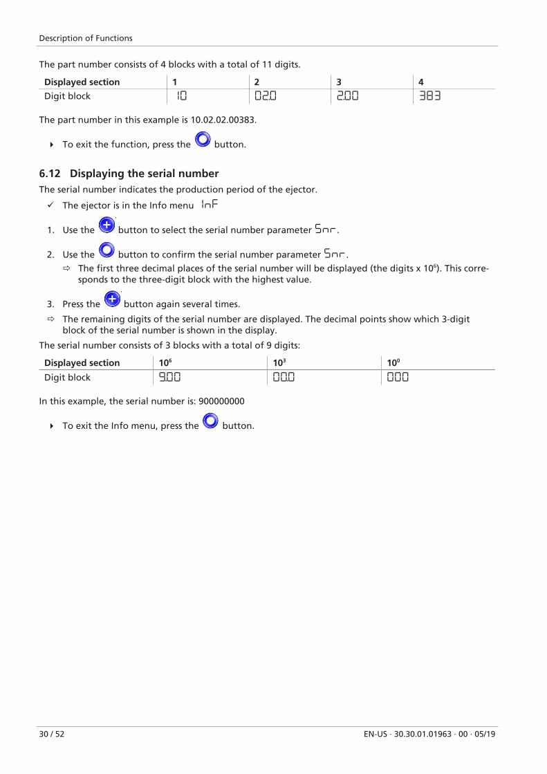
The part number consists of 4 blocks with a total of 11 digits.
Displayed section 1 2 3 4
Digit block 10 02.0 2.00 383
The part number in this example is 10.02.02.00383.
4 To exit the function, press the button.
6.12 Displaying the serial numberThe serial number indicates the production period of the ejector.
ü The ejector is in the Info menu 1NF
1. Use the button to select the serial number parameter 5nr.
2. Use the button to confirm the serial number parameter 5nr.
ð The first three decimal places of the serial number will be displayed (the digits x 106). This corre-sponds to the three-digit block with the highest value.
3. Press the button again several times.
ð The remaining digits of the serial number are displayed. The decimal points show which 3-digitblock of the serial number is shown in the display.
The serial number consists of 3 blocks with a total of 9 digits:
Displayed section 106 103 100
Digit block 9.00 00.0 000
In this example, the serial number is: 900000000
4 To exit the Info menu, press the button.
Description of Functions
EN-US · 30.30.01.01963 · 00 · 05/19 31 / 52
6.13 Condition Monitoring (CM)
6.13.1 Evacuation Time Monitoring
Vacuum[mbar]
Time [s]Start suction cycle
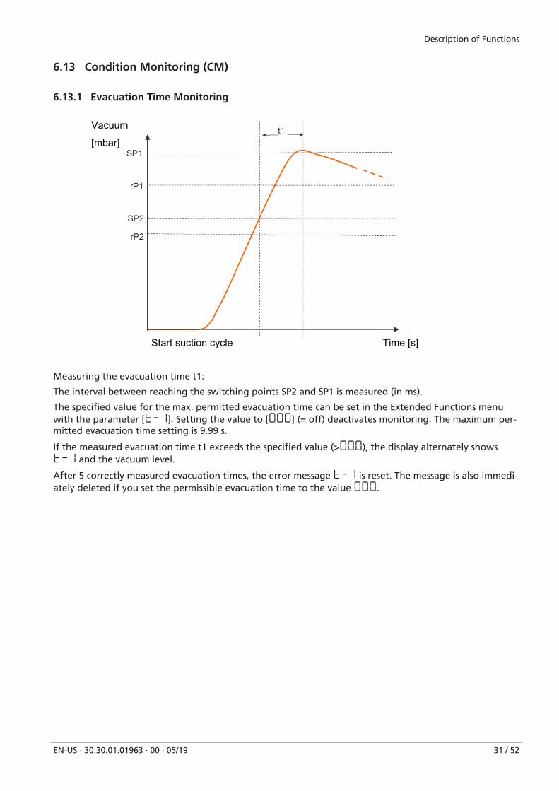
Measuring the evacuation time t1:
The interval between reaching the switching points SP2 and SP1 is measured (in ms).
The specified value for the max. permitted evacuation time can be set in the Extended Functions menuwith the parameter [t-1]. Setting the value to [000] (= off) deactivates monitoring. The maximum per-mitted evacuation time setting is 9.99 s.
If the measured evacuation time t1 exceeds the specified value (>000), the display alternately showst-1 and the vacuum level.
After 5 correctly measured evacuation times, the error message t-1 is reset. The message is also immedi-ately deleted if you set the permissible evacuation time to the value 000.
Description of Functions
32 / 52 EN-US · 30.30.01.01963 · 00 · 05/19
6.13.2 Leakage monitoring
Vacuum
Time
SP1
rP1
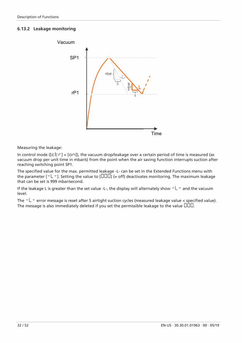
Measuring the leakage:
In control mode ([ctr] = [on]), the vacuum drop/leakage over a certain period of time is measured (asvacuum drop per unit time in mbar/s) from the point when the air saving function interrupts suction afterreaching switching point SP1.
The specified value for the max. permitted leakage -L- can be set in the Extended Functions menu withthe parameter [-L-]. Setting the value to [000] (= off) deactivates monitoring. The maximum leakagethat can be set is 999 mbar/second.
If the leakage L is greater than the set value -L-, the display will alternately show -L- and the vacuumlevel.
The -L- error message is reset after 5 airtight suction cycles (measured leakage value < specified value).The message is also immediately deleted if you set the permissible leakage to the value 000.
Transport and storage
EN-US · 30.30.01.01963 · 00 · 05/19 33 / 52
7 Transport and storage
7.1 Checking the DeliveryThe scope of delivery can be found in the order confirmation. The weights and dimensions are listed inthe delivery notes.
1. Compare the entire delivery with the supplied delivery notes to make sure nothing is missing.
2. Damage caused by defective packaging or in transit must be reported immediately to the carrier andJ. Schmalz GmbH.
Installation
34 / 52 EN-US · 30.30.01.01963 · 00 · 05/19
8 Installation
8.1 Installation Instructions
CAUTIONImproper installation or maintenance
Personal injury or damage to property
4 During installation and maintenance, make sure that the ejector is disconnected anddepressurized and that it cannot be switched on again without authorization.
For safe installation, the following instructions must be observed:
1. Use only the connections, mounting holes and attachment materials that have been provided.
2. Carry out mounting and removal only when the device is in an idle, depressurized state.
3. Pneumatic and electrical line connections must be securely connected and attached to the ejector.
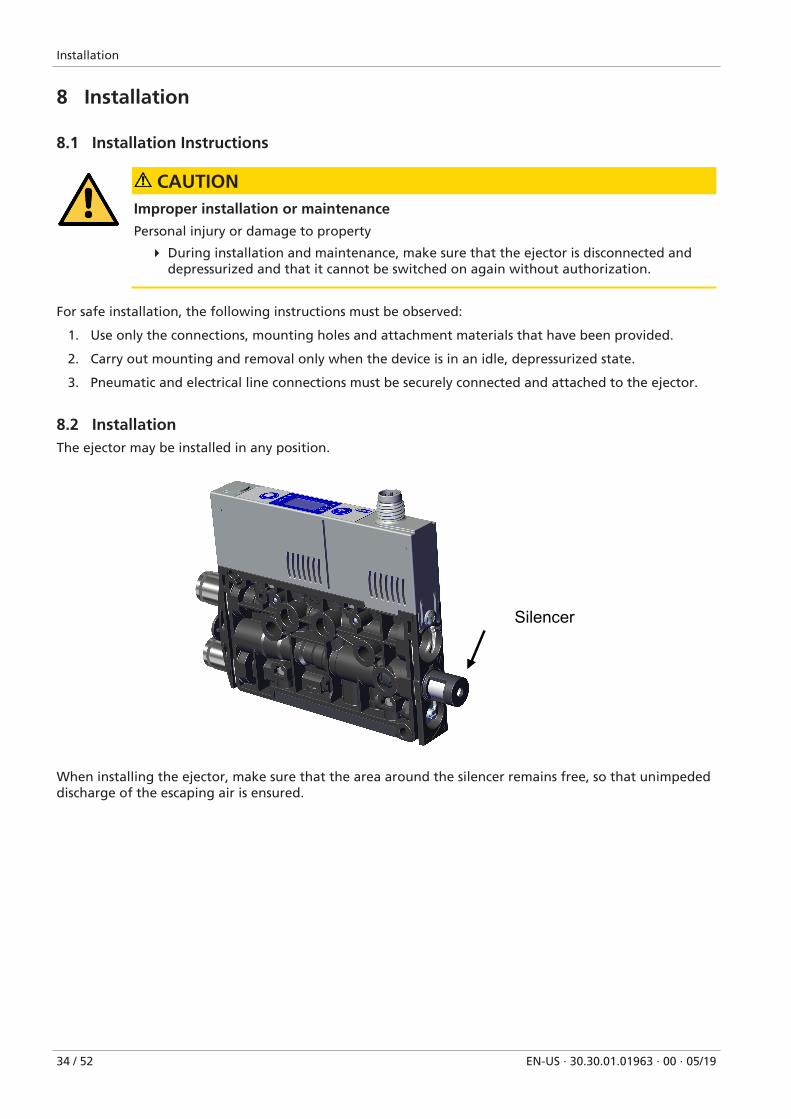
8.2 InstallationThe ejector may be installed in any position.
Silencer
When installing the ejector, make sure that the area around the silencer remains free, so that unimpededdischarge of the escaping air is ensured.
Installation
EN-US · 30.30.01.01963 · 00 · 05/19 35 / 52
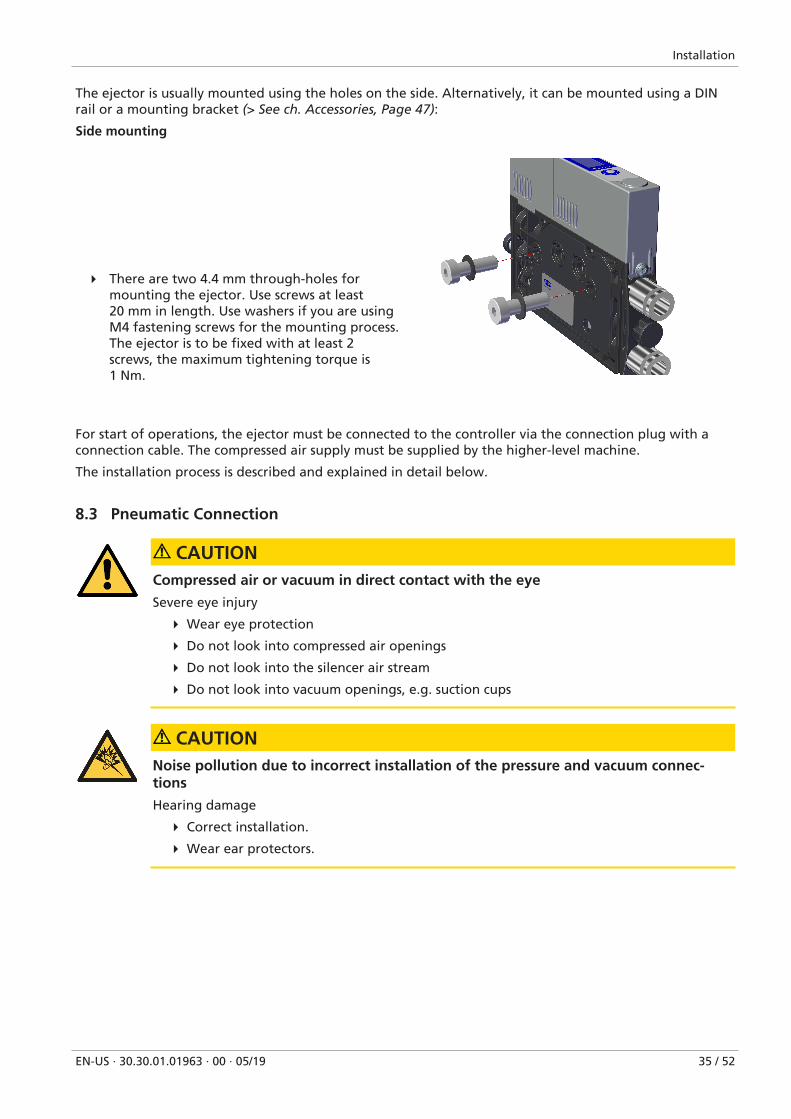
The ejector is usually mounted using the holes on the side. Alternatively, it can be mounted using a DINrail or a mounting bracket (> See ch. Accessories, Page 47):
Side mounting
4 There are two 4.4 mm through-holes formounting the ejector. Use screws at least20 mm in length. Use washers if you are usingM4 fastening screws for the mounting process.The ejector is to be fixed with at least 2screws, the maximum tightening torque is1 Nm.
For start of operations, the ejector must be connected to the controller via the connection plug with aconnection cable. The compressed air supply must be supplied by the higher-level machine.
The installation process is described and explained in detail below.
8.3 Pneumatic Connection
CAUTIONCompressed air or vacuum in direct contact with the eye
Severe eye injury
4 Wear eye protection
4 Do not look into compressed air openings
4 Do not look into the silencer air stream
4 Do not look into vacuum openings, e.g. suction cups
CAUTIONNoise pollution due to incorrect installation of the pressure and vacuum connec-tions
Hearing damage
4 Correct installation.
4 Wear ear protectors.
Installation
36 / 52 EN-US · 30.30.01.01963 · 00 · 05/19
8.3.1 Connecting the Compressed Air and Vacuum
Description of the pneumatic connection
1
2
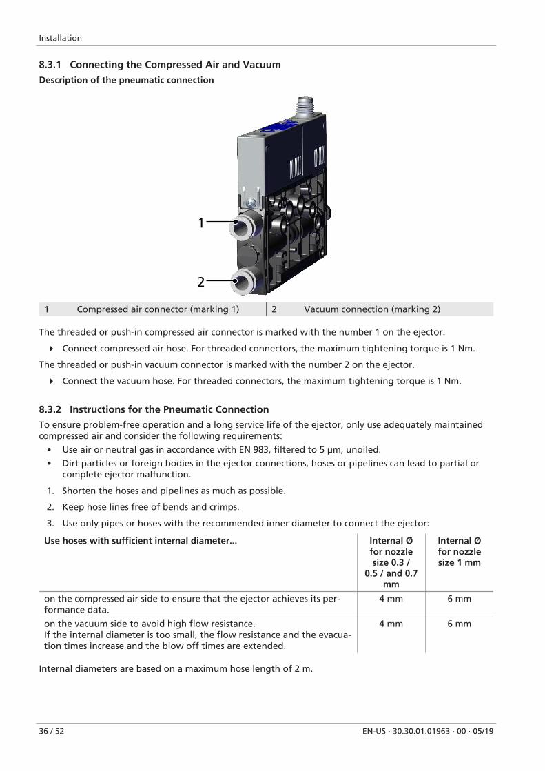
1 Compressed air connector (marking 1) 2 Vacuum connection (marking 2)
The threaded or push-in compressed air connector is marked with the number 1 on the ejector.
4 Connect compressed air hose. For threaded connectors, the maximum tightening torque is 1 Nm.
The threaded or push-in vacuum connector is marked with the number 2 on the ejector.
4 Connect the vacuum hose. For threaded connectors, the maximum tightening torque is 1 Nm.
8.3.2 Instructions for the Pneumatic Connection
To ensure problem-free operation and a long service life of the ejector, only use adequately maintainedcompressed air and consider the following requirements:
• Use air or neutral gas in accordance with EN 983, filtered to 5 μm, unoiled.
• Dirt particles or foreign bodies in the ejector connections, hoses or pipelines can lead to partial orcomplete ejector malfunction.
1. Shorten the hoses and pipelines as much as possible.
2. Keep hose lines free of bends and crimps.
3. Use only pipes or hoses with the recommended inner diameter to connect the ejector:
Use hoses with sufficient internal diameter... Internal Øfor nozzlesize 0.3 /
0.5 / and 0.7mm
Internal Øfor nozzlesize 1 mm
on the compressed air side to ensure that the ejector achieves its per-formance data.
4 mm 6 mm
on the vacuum side to avoid high flow resistance.If the internal diameter is too small, the flow resistance and the evacua-tion times increase and the blow off times are extended.
4 mm 6 mm
Internal diameters are based on a maximum hose length of 2 m.
Installation
EN-US · 30.30.01.01963 · 00 · 05/19 37 / 52
8.3.3 Optional: External blow-off connection (EB)
The ejector is also optionally available with an additional compressed air connector for the blow off func-tion.
With the external blow off function (EB), the blow off pulse is controlled separately and independently ofthe compressed air supply for vacuum generation, allowing you to use a different medium (e.g. nitrogen)for the blow off function.
It also allows you to precisely set the blow off pressure using an external pressure regulator (between 2and 6 bar).
The blow off flow rate can also be set between 0% and 100% directly on the ejector. This can be used, forexample, to set down small and lightweight workpieces with high positioning precision.
The hose size and the thread on the connector depend on the particular ejector and can have the follow-ing dimensions:
• Push-in: 4/2
• M5 female thread
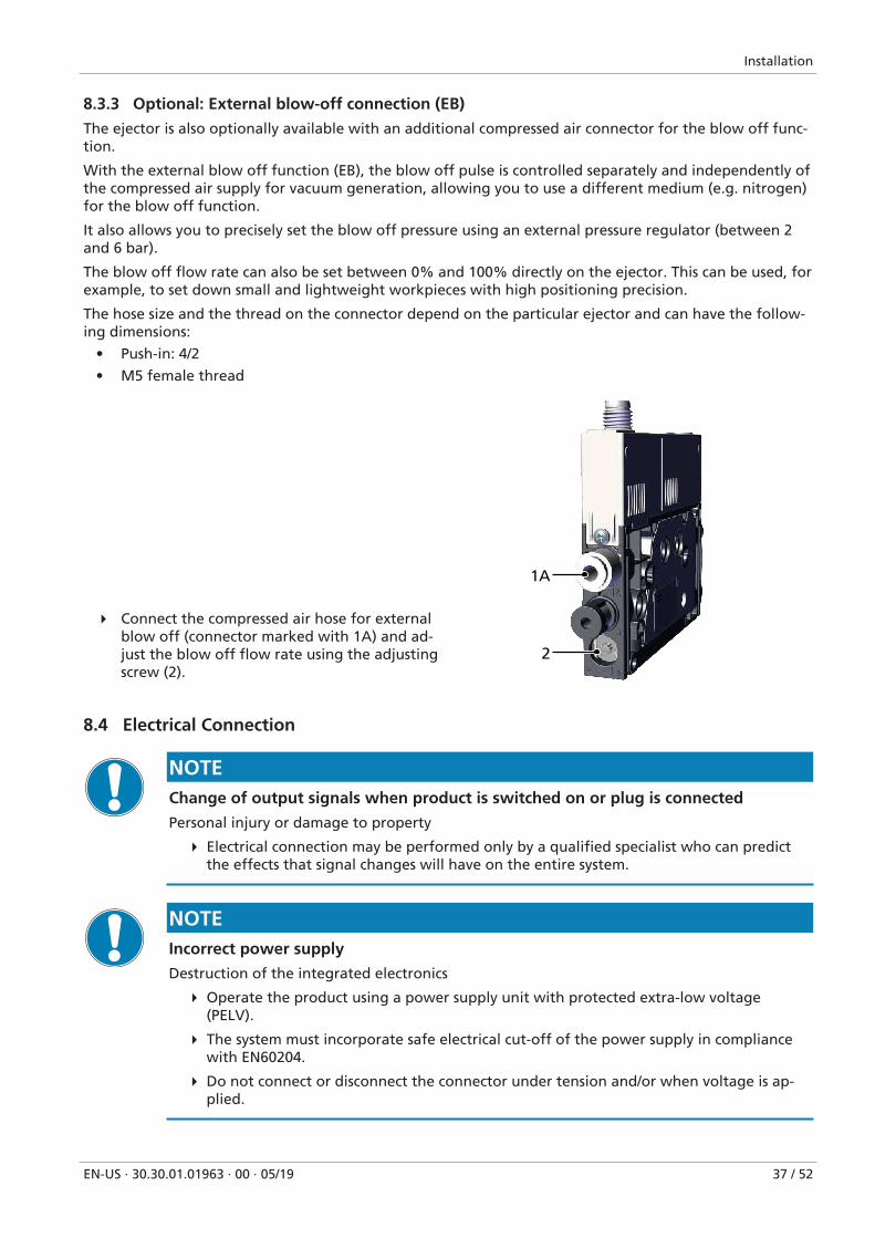
4 Connect the compressed air hose for externalblow off (connector marked with 1A) and ad-just the blow off flow rate using the adjustingscrew (2).
1A
2
8.4 Electrical Connection
NOTEChange of output signals when product is switched on or plug is connected
Personal injury or damage to property
4 Electrical connection may be performed only by a qualified specialist who can predictthe effects that signal changes will have on the entire system.
NOTEIncorrect power supply
Destruction of the integrated electronics
4 Operate the product using a power supply unit with protected extra-low voltage(PELV).
4 The system must incorporate safe electrical cut-off of the power supply in compliancewith EN60204.
4 Do not connect or disconnect the connector under tension and/or when voltage is ap-plied.
Installation
38 / 52 EN-US · 30.30.01.01963 · 00 · 05/19
The electrical connection supplies the ejector with power and communicates with the control system ofthe higher-level machine using defined outputs.
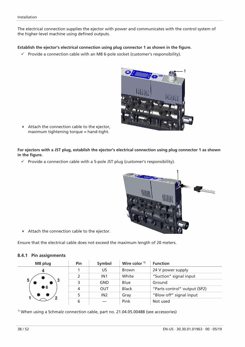
Establish the ejector’s electrical connection using plug connector 1 as shown in the figure.
ü Provide a connection cable with an M8 6-pole socket (customer’s responsibility).
4 Attach the connection cable to the ejector,maximum tightening torque = hand-tight.
1
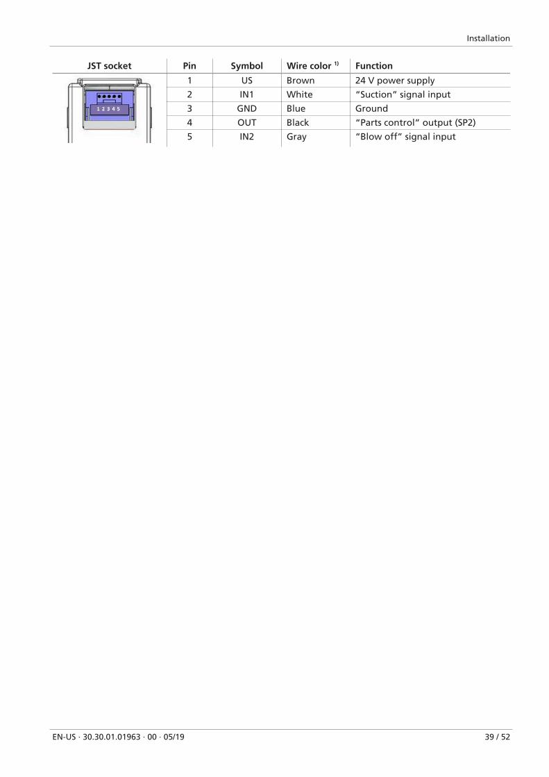
For ejectors with a JST plug, establish the ejector’s electrical connection using plug connector 1 as shownin the figure.
ü Provide a connection cable with a 5-pole JST plug (customer’s responsibility).
4 Attach the connection cable to the ejector.
1
Ensure that the electrical cable does not exceed the maximum length of 20 meters.
8.4.1 Pin assignments
M8 plug Pin Symbol Wire color 1) Function
1 US Brown 24 V power supply
2 IN1 White “Suction” signal input
3 GND Blue Ground
4 OUT Black “Parts control” output (SP2)
5 IN2 Gray “Blow off” signal input
6 — Pink Not used
1) When using a Schmalz connection cable, part no. 21.04.05.00488 (see accessories)
Installation
EN-US · 30.30.01.01963 · 00 · 05/19 39 / 52
JST socket Pin Symbol Wire color 1) Function
1 US Brown 24 V power supply
2 IN1 White “Suction” signal input
3 GND Blue Ground
4 OUT Black “Parts control” output (SP2)
5 IN2 Gray “Blow off” signal input
Operation
40 / 52 EN-US · 30.30.01.01963 · 00 · 05/19
9 Operation
9.1 General Preparations
WARNINGExtraction of hazardous media, liquids or bulk material
Personal injury or damage to property!
4 Do not extract harmful media such as dust, oil mists, vapors, aerosols etc.
4 Do not extract aggressive gases or media such as acids, acid fumes, bases, biocides, dis-infectants or detergents.
4 Do not extract liquids or bulk materials, e.g. granulates.
Always carry out the following tasks before activating the system:
1. Before each use, check that the safety devices are in perfect condition.
2. Check the ejector for visible damage and deal with any problems immediately (or notify your super-visor).
3. Ensure that only authorized personnel are present in the working area of the machine or system andthat no other personnel are put in danger by switching on the machine.
There must be no people in the system danger area while it is in operation.
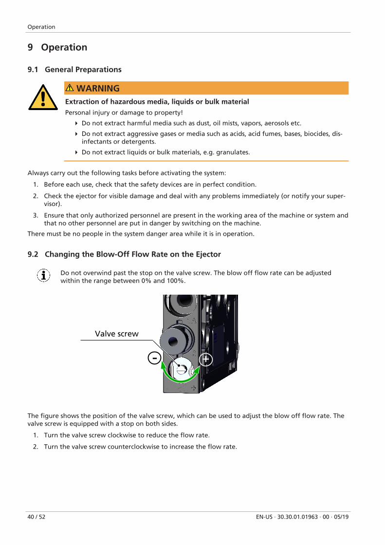
9.2 Changing the Blow-Off Flow Rate on the Ejector
Do not overwind past the stop on the valve screw. The blow off flow rate can be adjustedwithin the range between 0% and 100%.
Valve screw
+-
The figure shows the position of the valve screw, which can be used to adjust the blow off flow rate. Thevalve screw is equipped with a stop on both sides.
1. Turn the valve screw clockwise to reduce the flow rate.
2. Turn the valve screw counterclockwise to increase the flow rate.
Troubleshooting
EN-US · 30.30.01.01963 · 00 · 05/19 41 / 52
10 Troubleshooting
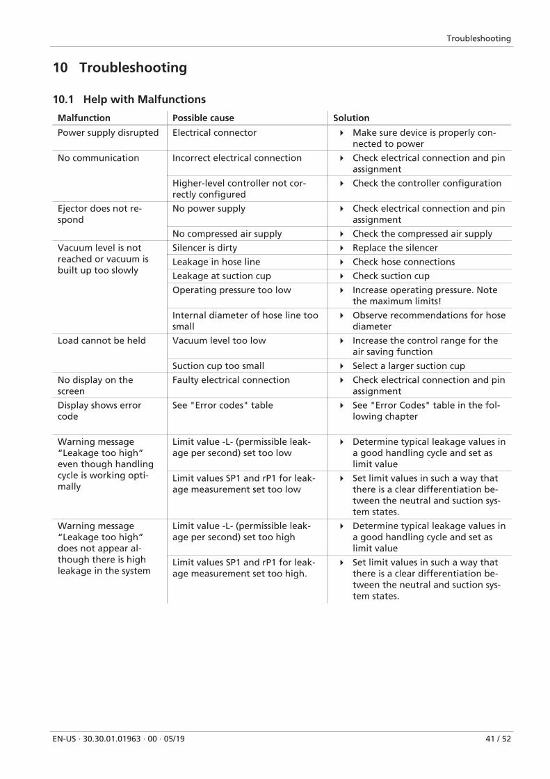
10.1 Help with Malfunctions
Malfunction Possible cause Solution
Power supply disrupted Electrical connector 4 Make sure device is properly con-nected to power
No communication Incorrect electrical connection 4 Check electrical connection and pinassignment
Higher-level controller not cor-rectly configured
4 Check the controller configuration
Ejector does not re-spond
No power supply 4 Check electrical connection and pinassignment
No compressed air supply 4 Check the compressed air supply
Vacuum level is notreached or vacuum isbuilt up too slowly
Silencer is dirty 4 Replace the silencer
Leakage in hose line 4 Check hose connections
Leakage at suction cup 4 Check suction cup
Operating pressure too low 4 Increase operating pressure. Notethe maximum limits!
Internal diameter of hose line toosmall
4 Observe recommendations for hosediameter
Load cannot be held Vacuum level too low 4 Increase the control range for theair saving function
Suction cup too small 4 Select a larger suction cup
No display on thescreen
Faulty electrical connection 4 Check electrical connection and pinassignment
Display shows errorcode
See "Error codes" table 4 See "Error Codes" table in the fol-lowing chapter
Warning message“Leakage too high”even though handlingcycle is working opti-mally
Limit value -L- (permissible leak-age per second) set too low
4 Determine typical leakage values ina good handling cycle and set aslimit value
Limit values SP1 and rP1 for leak-age measurement set too low
4 Set limit values in such a way thatthere is a clear differentiation be-tween the neutral and suction sys-tem states.
Warning message“Leakage too high”does not appear al-though there is highleakage in the system
Limit value -L- (permissible leak-age per second) set too high
4 Determine typical leakage values ina good handling cycle and set aslimit value
Limit values SP1 and rP1 for leak-age measurement set too high.
4 Set limit values in such a way thatthere is a clear differentiation be-tween the neutral and suction sys-tem states.
Troubleshooting
42 / 52 EN-US · 30.30.01.01963 · 00 · 05/19
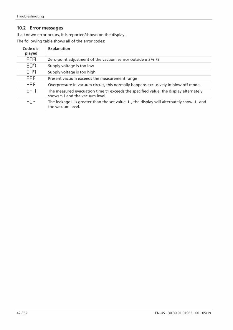
10.2 Error messagesIf a known error occurs, it is reported/shown on the display.
The following table shows all of the error codes:
Code dis-played
Explanation
E03 Zero-point adjustment of the vacuum sensor outside ± 3% FS
E07 Supply voltage is too low
E17 Supply voltage is too high
FFF Present vacuum exceeds the measurement range
-FF Overpressure in vacuum circuit, this normally happens exclusively in blow off mode.
t-1 The measured evacuation time t1 exceeds the specified value, the display alternatelyshows t-1 and the vacuum level.
-L- The leakage L is greater than the set value -L-, the display will alternately show -L- andthe vacuum level.
Maintenance
EN-US · 30.30.01.01963 · 00 · 05/19 43 / 52
11 Maintenance
11.1 SafetyMaintenance work may only be carried out by qualified personnel.
WARNINGRisk of injury due to incorrect maintenance or troubleshooting
4 Check the proper functioning of the product, especially the safety features, after everymaintenance or troubleshooting operation.
NOTEIncorrect maintenance work
Damage to the ejector!
4 Always switch off supply voltage before carrying out any maintenance work.
4 Secure it so that it cannot be switched back on.
4 The ejector must only be operated with a silencer.
4 Before carrying out any work on the system, ensure that the ejector’s compressed air circuit isvented to atmospheric pressure!
11.2 Cleaning the Ejector
1. For cleaning, do not use aggressive cleaning agents such as industrial alcohol, white spirit or thin-ners. Only use cleaning agents with pH 7–12.
2. Remove dirt on the exterior of the device with a soft cloth and soap suds at a maximum tempera-ture of 60° C. Make sure that the silencer is not soaked in soapy water.
3. Ensure that no moisture can reach the electrical connection or other electrical components.
Maintenance
44 / 52 EN-US · 30.30.01.01963 · 00 · 05/19
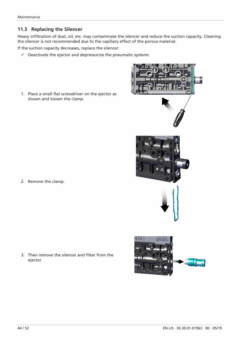
11.3 Replacing the SilencerHeavy infiltration of dust, oil, etc. may contaminate the silencer and reduce the suction capacity. Cleaningthe silencer is not recommended due to the capillary effect of the porous material.
If the suction capacity decreases, replace the silencer:
ü Deactivate the ejector and depressurize the pneumatic systems.
1. Place a small flat screwdriver on the ejector asshown and loosen the clamp.
2. Remove the clamp.
3. Then remove the silencer and filter from theejector.
Maintenance
EN-US · 30.30.01.01963 · 00 · 05/19 45 / 52
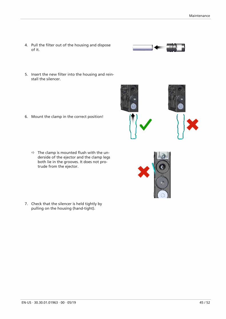
4. Pull the filter out of the housing and disposeof it.
5. Insert the new filter into the housing and rein-stall the silencer.
6. Mount the clamp in the correct position!
ð The clamp is mounted flush with the un-derside of the ejector and the clamp legsboth lie in the grooves. It does not pro-trude from the ejector.
7. Check that the silencer is held tightly bypulling on the housing (hand-tight).
Warranty
46 / 52 EN-US · 30.30.01.01963 · 00 · 05/19
12 WarrantyThis system is guaranteed in accordance with our general terms of trade and delivery. The same applies tospare parts, provided that these are original parts supplied by us.
We are not liable for any damage resulting from the use of non-original spare parts or accessories.
The exclusive use of original spare parts is a prerequisite for the proper functioning of the ejector and forthe validity of the warranty.
Wearing parts are not covered by the warranty.
Opening the ejector will damage the "tested" labels. This voids the warranty.
Spare and Wearing Parts, Accessories
EN-US · 30.30.01.01963 · 00 · 05/19 47 / 52
13 Spare and Wearing Parts, Accessories
13.1 Spare and Wearing PartsMaintenance work may only be carried out by qualified personnel.
WARNINGRisk of injury due to incorrect maintenance or troubleshooting
4 Check the proper functioning of the product, especially the safety features, after everymaintenance or troubleshooting operation.
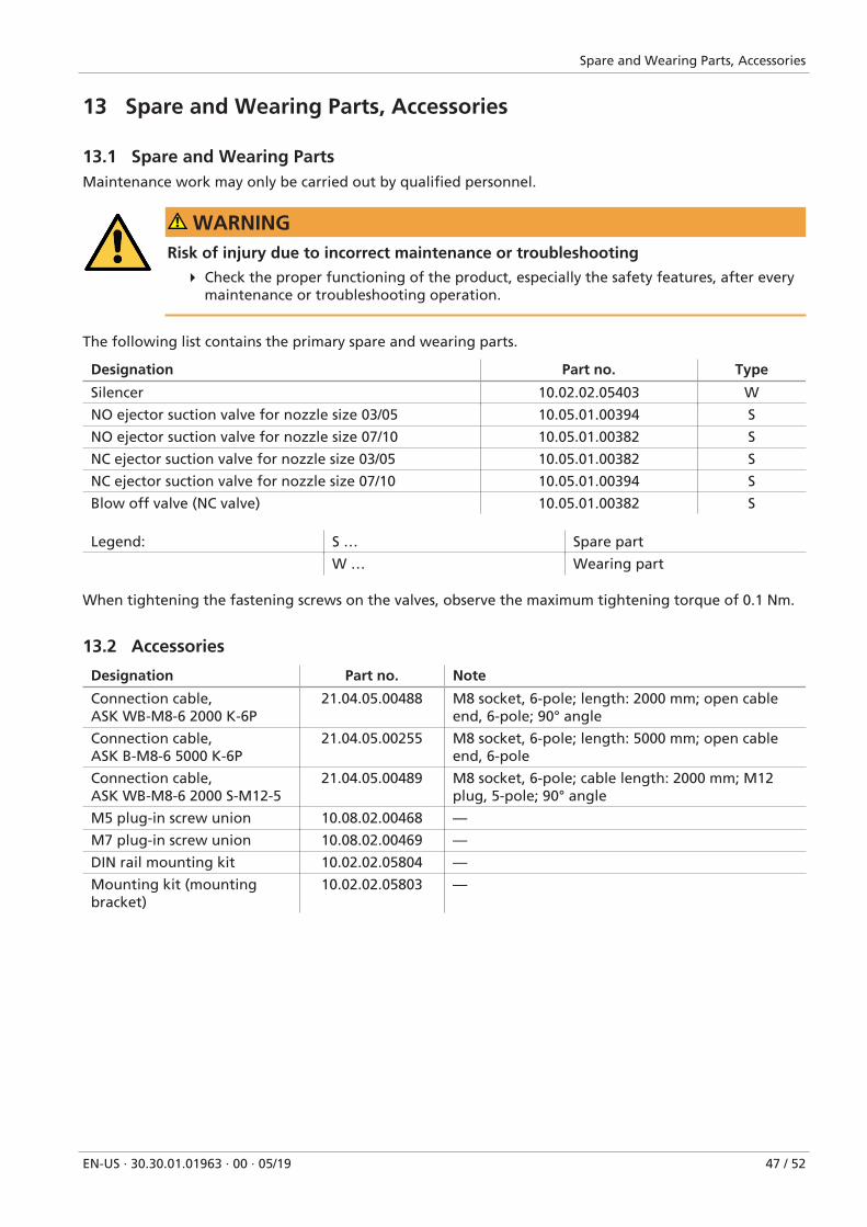
The following list contains the primary spare and wearing parts.
Designation Part no. Type
Silencer 10.02.02.05403 W
NO ejector suction valve for nozzle size 03/05 10.05.01.00394 S
NO ejector suction valve for nozzle size 07/10 10.05.01.00382 S
NC ejector suction valve for nozzle size 03/05 10.05.01.00382 S
NC ejector suction valve for nozzle size 07/10 10.05.01.00394 S
Blow off valve (NC valve) 10.05.01.00382 S
Legend: S … Spare part
W … Wearing part
When tightening the fastening screws on the valves, observe the maximum tightening torque of 0.1 Nm.
13.2 Accessories
Designation Part no. Note
Connection cable,ASK WB-M8-6 2000 K-6P
21.04.05.00488 M8 socket, 6-pole; length: 2000 mm; open cableend, 6-pole; 90° angle
Connection cable,ASK B-M8-6 5000 K-6P
21.04.05.00255 M8 socket, 6-pole; length: 5000 mm; open cableend, 6-pole
Connection cable,ASK WB-M8-6 2000 S-M12-5
21.04.05.00489 M8 socket, 6-pole; cable length: 2000 mm; M12plug, 5-pole; 90° angle
M5 plug-in screw union 10.08.02.00468 —
M7 plug-in screw union 10.08.02.00469 —
DIN rail mounting kit 10.02.02.05804 —
Mounting kit (mountingbracket)
10.02.02.05803 —
Decommissioning and recycling
48 / 52 EN-US · 30.30.01.01963 · 00 · 05/19
14 Decommissioning and recycling
14.1 Disposing of the Ejector
1. Dispose of the product properly after replacement or decommissioning.
2. Observe the country-specific guidelines and legal obligations for waste prevention and disposal.
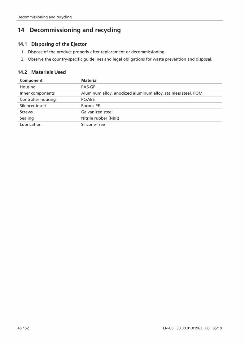
14.2 Materials Used
Component Material
Housing PA6-GF
Inner components Aluminum alloy, anodized aluminum alloy, stainless steel, POM
Controller housing PC/ABS
Silencer insert Porous PE
Screws Galvanized steel
Sealing Nitrile rubber (NBR)
Lubrication Silicone-free
Appendix
EN-US · 30.30.01.01963 · 00 · 05/19 49 / 52
15 Appendix
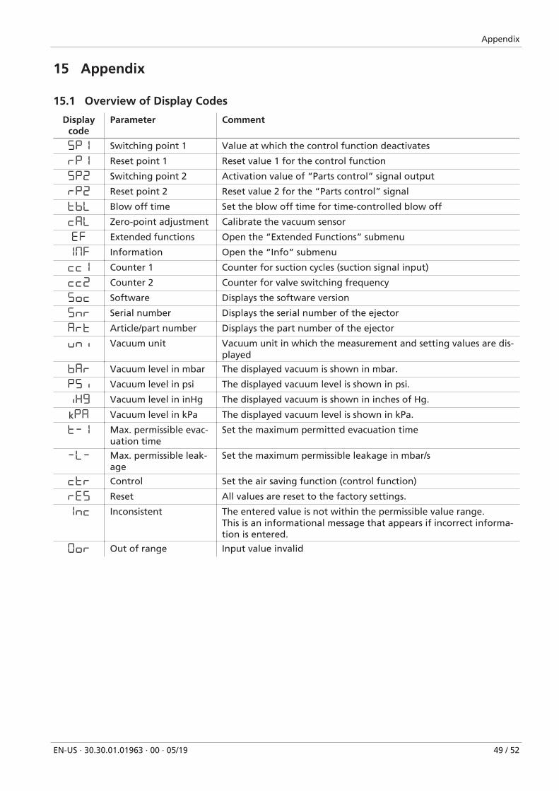
15.1 Overview of Display Codes
Displaycode
Parameter Comment
5P1 Switching point 1 Value at which the control function deactivates
rP1 Reset point 1 Reset value 1 for the control function
5P2 Switching point 2 Activation value of “Parts control” signal output
rP2 Reset point 2 Reset value 2 for the “Parts control” signal
tbL Blow off time Set the blow off time for time-controlled blow off
CAL Zero-point adjustment Calibrate the vacuum sensor
EF Extended functions Open the “Extended Functions” submenu
1mF Information Open the “Info” submenu
cc1 Counter 1 Counter for suction cycles (suction signal input)
cc2 Counter 2 Counter for valve switching frequency
5oc Software Displays the software version
5nr Serial number Displays the serial number of the ejector
Art Article/part number Displays the part number of the ejector
uni Vacuum unit Vacuum unit in which the measurement and setting values are dis-played
bAr Vacuum level in mbar The displayed vacuum is shown in mbar.
P5i Vacuum level in psi The displayed vacuum level is shown in psi.
iX9 Vacuum level in inHg The displayed vacuum is shown in inches of Hg.
kPA Vacuum level in kPa The displayed vacuum level is shown in kPa.
t-1 Max. permissible evac-uation time
Set the maximum permitted evacuation time
-L- Max. permissible leak-age
Set the maximum permissible leakage in mbar/s
Ctr Control Set the air saving function (control function)
rE5 Reset All values are reset to the factory settings.
1nc Inconsistent The entered value is not within the permissible value range.This is an informational message that appears if incorrect informa-tion is entered.
0or Out of range Input value invalid
Appendix
50 / 52 EN-US · 30.30.01.01963 · 00 · 05/19
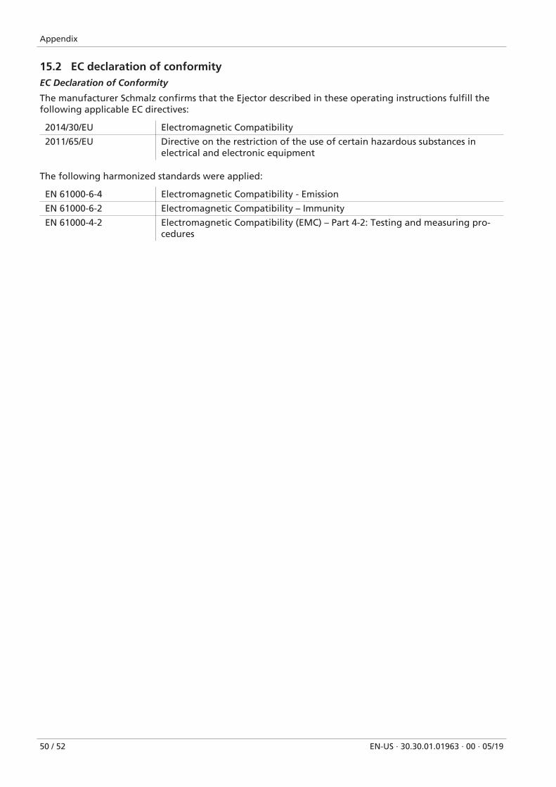
15.2 EC declaration of conformityEC Declaration of Conformity
The manufacturer Schmalz confirms that the Ejector described in these operating instructions fulfill thefollowing applicable EC directives:
2014/30/EU Electromagnetic Compatibility
2011/65/EU Directive on the restriction of the use of certain hazardous substances inelectrical and electronic equipment
The following harmonized standards were applied:
EN 61000-6-4 Electromagnetic Compatibility - Emission
EN 61000-6-2 Electromagnetic Compatibility – Immunity
EN 61000-4-2 Electromagnetic Compatibility (EMC) – Part 4-2: Testing and measuring pro-cedures

30.30.01.01963 · 00 · 05/19 51 / 52

© J
. Sch
mal
z G
mb
H ·
EN-U
S · 3
0.30
.01.
0196
3 · 0
0 · 0
5/19
· Su
bje
ct t
o t
ech
nic
al c
han
ges
wit
ho
ut
no
tice