Embed Size (px)
Citation preview
SRB 324ST V.3Operating instructionsSafety-monitoring module
1EN
EN Operating instructions...................... pages 1 to 8Translation of the original operating instructions
1 About this document
1.1 FunctionThis operating instructions manual provides all the information you need for the mounting, set-up and commissioning to ensure the safe operation and disassembly of the safety-monitoring module. The operating instruc-tions must be available in a legible condition and a complete version in the vicinity of the device.
1.2 Target group: authorised qualified personnelAll operations described in this operating instructions manual must be carried out by trained specialist personnel, authorised by the plant operator only.
Please make sure that you have read and understood these operating instructions and that you know all applicable legislations regarding occupational safety and accident prevention prior to installation and putting the component into operation.
The machine builder must carefully select the harmonised standards to be complied with as well as other technical specifications for the selection, mounting and integration of the components.
1.3 Explanation of the symbols used
Information, hint, note:This symbol is used for identifying useful additional information.
Caution: Failure to comply with this warning notice could lead to failures or malfunctions.Warning: Failure to comply with this warning notice could lead to physical injury and/or damage to the machine.
1.4 Appropriate useThe products described in these operating instructions are developed to execute safety-related functions as part of an entire plant or machine. It is the responsibility of the manufacturer of a machine or plant to ensure the proper functionality of the entire machinery or plant.
The safety-monitoring module must be exclusively used in accordance with the versions listed below or for the applications authorised by the manufacturer. Detailed information regarding the range of applications can be found in the chapter "Product description".
1.5 General safety instructionsThe user must observe the safety instructions in this operating instruc-tions manual, the country-specific installation standards as well as all prevailing safety regulations and accident prevention rules.
Further technical information can be found in the Elan catalogues or in the online catalogue on the Internet: www.schmersal.net.
The information contained in this operating instructions manual is provided without liability. Subject to technical modifications.
There are no residual risks, provided that the safety instructions as well as the instructions regarding mounting, commissioning, operation and maintenance are observed.
1.6 Warning about misuse
In case of inadequate or improper use or manipulations of the safety-monitoring module, personal hazards or damage to machinery or plant components cannot be excluded. The relevant requirements of the standard EN 1088 must be observed.
09.1
2.20
09 /
Inde
x: 4
79/0
9 / T
eile
-Nr.
1194
424-
EN
Content
1 About this document1.1 Function . . . . . . . . . . . . . . . . . . . . . . . . . . . . . . . . . . . . . . . . . . . . . .11.2 Target group: authorised qualified personnel. . . . . . . . . . . . . . . . . .11.3 Explanation of the symbols used . . . . . . . . . . . . . . . . . . . . . . . . . . .11.4 Appropriate use . . . . . . . . . . . . . . . . . . . . . . . . . . . . . . . . . . . . . . . .11.5 General safety instructions . . . . . . . . . . . . . . . . . . . . . . . . . . . . . . .11.6 Warning about misuse . . . . . . . . . . . . . . . . . . . . . . . . . . . . . . . . . . .11.7 Exclusion of liability . . . . . . . . . . . . . . . . . . . . . . . . . . . . . . . . . . . . .2
2 Product description2.1 Ordering code . . . . . . . . . . . . . . . . . . . . . . . . . . . . . . . . . . . . . . . . .22.2 Special versions. . . . . . . . . . . . . . . . . . . . . . . . . . . . . . . . . . . . . . . .22.3 Destination and use . . . . . . . . . . . . . . . . . . . . . . . . . . . . . . . . . . . . .22.4 Technical data . . . . . . . . . . . . . . . . . . . . . . . . . . . . . . . . . . . . . . . . .22.5 Safety classification . . . . . . . . . . . . . . . . . . . . . . . . . . . . . . . . . . . . .3
3 Mounting3.1 General mounting instructions . . . . . . . . . . . . . . . . . . . . . . . . . . . . .33.2 Dimensions . . . . . . . . . . . . . . . . . . . . . . . . . . . . . . . . . . . . . . . . . . .3
4 Electrical connection4.1 General information for electrical connection. . . . . . . . . . . . . . . . . .3
5 Operating principle and settings5.1 Notes . . . . . . . . . . . . . . . . . . . . . . . . . . . . . . . . . . . . . . . . . . . . . . . .45.2 Setting report SRB 324ST V.3 . . . . . . . . . . . . . . . . . . . . . . . . . . . . .5
6 Set-up and maintenance6.1 Functional testing. . . . . . . . . . . . . . . . . . . . . . . . . . . . . . . . . . . . . . .56.2 Maintenance . . . . . . . . . . . . . . . . . . . . . . . . . . . . . . . . . . . . . . . . . .5
7 Disassembly and disposal7.1 Disassembly. . . . . . . . . . . . . . . . . . . . . . . . . . . . . . . . . . . . . . . . . . .57.2 Disposal . . . . . . . . . . . . . . . . . . . . . . . . . . . . . . . . . . . . . . . . . . . . . .5
8 Appendix8.1 Wiring examples . . . . . . . . . . . . . . . . . . . . . . . . . . . . . . . . . . . . . . .58.2 Start configuration . . . . . . . . . . . . . . . . . . . . . . . . . . . . . . . . . . . . . .58.3 Sensor configuration . . . . . . . . . . . . . . . . . . . . . . . . . . . . . . . . . . . .68.4 Actuator configuration . . . . . . . . . . . . . . . . . . . . . . . . . . . . . . . . . . .78.5 EC Declaration of conformity . . . . . . . . . . . . . . . . . . . . . . . . . . . . . .8
2
Operating instructionsSafety-monitoring module SRB 324ST V.3
EN
1.7 Exclusion of liabilityWe shall accept no liability for damages and malfunctions resulting from defective mounting or failure to comply with this operating instructions manual. The manufacturer shall accept no liability for damages resulting from the use of unauthorised spare parts or accessories.
For safety reasons, invasive work on the device as well as arbitrary re-pairs, conversions and modifications to the device are strictly forbidden; the manufacturer shall accept no liability for damages resulting from such invasive work, arbitrary repairs, conversions and/or modifications to the device.
2 Product description
2.1 Ordering codeThis operating instructions manual applies to the following types:
SRB 324ST V.3
Only if the information described in this operating instructions manual are realised correctly, the safety function and therefore the compliance with the Machinery Directive is maintained.
2.2 Special versionsFor special versions, which are not listed in the order code below 2.1, these specifications apply accordingly, provided that they correspond to the standard version.
2.3 Destination and useThe safety-monitoring modules for integration in safety circuits are designed for fitting in control cabinets. They are used for the safe evaluation of the signals of positive break position switches for safety functions or magnetic safety sensors on sliding, hinged and removable safety guards as well as emergency stop control devices and AOPD's (safety light barriers).
The safety function is defined as the opening of the enabling circuits 13-14, 23-24 and 33-34 and the delayed opening of the enabling circuits 47-48 and 57-58 when the inputs S11-S12 and/or S21-S22 are opened. The safety-relevant current paths with the output contacts 13-14, 23-24 and 33-34 meet the following requirements under observation of a B10d value assessment (also refer to "Requirements to DIN EN ISO 13849-1"): – control category 4 – PL e to DIN EN ISO 13849-1 – corresponds to SIL 3 to DIN EN 61508-2 – corresponds to SILCL 3 to DIN EN 62061
(corresponds to control category 4 to DIN EN 954-1)
The safety-relevant current path with the output contacts 47-48 and 57-58 meets the following requirements under observation of a B10d value assessment (also refer to "Requirements to DIN EN ISO 13849-1"): – control category 3 – PL d to DIN EN ISO 13849-1 – corresponds to SIL 2 to DIN EN 61508-2 – corresponds to SILCL 2 to DIN EN 62061
(corresponds to control category 3 to DIN EN 954-1)
To determine the Performance Level (PL) of the entire safety function (e.g. sensor, logic, actuator) to DIN EN ISO 13849-1, an analysis of all relevant components is required.
2.4 Technical data
General data:Standards: IEC/EN 60204-1, EN 60947-5-1,
EN ISO 13849-1, IEC/EN 61508Climate resistance: EN 60068-2-78Fixing: Snaps onto standard DIN rails
to DIN EN 60715Terminal designations: EN 60947-1Material of the enclosure: glass-fibre reinforced thermoplastic,
ventilatedMaterial of the contacts: AgSnO, AgNi, self-cleaning,
positive driveWeight: 420 gStart conditions automatic or start button (monitored)Feedback circuit available: YesPull-in delay for automatic start:
typ. 400 ms
Pull-in delay with reset button:
typ. 30 ms
Drop-out delay in case of emergency stop:
typ. 30 ms
Drop-out delay on "supply failure":
typ. 80 ms
Mechanical data:Connection type: Screw terminalsCable section: min. 2 mm2 / max. 2 mm2
Connecting cable: rigid or flexibleTightening torque for the terminals:
0.6 Nm
With removable terminals: YesMechanical life: 10 million operationsResistance to shock: 10 g / 11 msResistance to vibrations to EN 60068-2-6:
10 … 55 Hz, amplitude 0.35 mm
Ambient temperature: –25°C … +60°CStorage and transport temperature:
–40°C … +85°C
Protection class: Enclosure: IP 40, Terminals: IP 20, Wiring compartment: IP 54
Air clearances and creepage distances to IEC/EN 60664-1:
4 kV/2 (basic insulation)
EMC rating: to EMC DirectiveElectrical data:Contact resistance in new state: max. 100 mΩPower consumption: max. 3.2 W / 7.1 VA 3 W,
plus signalling outputsRated operating voltage Ue: 24 VDC –15% / +20%,
residual ripple max. 10% 24 VAC –15% / +10%
Frequency range: 50 Hz / 60 HzMax. fuse rating of the operating voltage:
internal electronic fuse, tripping current F1: > 2.5 A; tripping current F2: > 50 mA (S11-S31) / 800 mA (X4)
Current and voltage at the control circuits:
S11, S12, S21, S22, S31, S32:24 VDC, 10 mAX1, X2: 24 VDC, start impulse 350 mA / 15 msX3, X4: 24 VDC, start impulse 130 mA / 80 msX4, X5: 24 VDC, start impulse 140 mA / 15 ms
Monitored inputs:Cross-wire detection: optionalWire breakage detection: YesEarth leakage detection: YesNumber of NO contacts: 0Number of NC contacts: 2Conduction resistance: max. 40 Ω
3
SRB 324ST V.3Operating instructionsSafety-monitoring module
EN
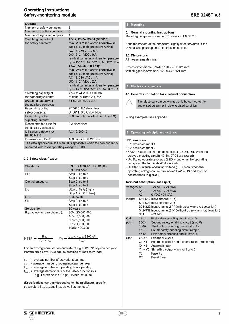
Outputs:Number of safety contacts: 5Number of auxiliary contacts: 0Number of signalling outputs: 1Switching capacity of the safety contacts:
13-14, 23-24, 33-34 (STOP 0):max. 250 V, 8 A ohmic (inductive in case of suitable protective wiring); AC-15: 230 VAC / 6 A, DC-13: 24 VDC / 6 A; residual current at ambient temperature up to 45°C: 18 A / 55°C: 15 A / 60°C: 12 A47-48, 57-58 (STOP 1):max. 250 V, 6 A ohmic (inductive in case of suitable protective wiring); AC-15: 230 VAC / 3 A, DC-13: 24 VDC / 2 A; residual current at ambient temperature up to 45°C: 12 A / 55°C: 10 A / 60°C: 8 A
Switching capacity of the signalling outputs:
Y1-Y3: 24 VDC / 100 mA, residual current: 200 mA
Switching capacity of the auxiliary contacts:
61-62: 24 VDC / 2 A
Fuse rating of the safety contacts:
STOP 0: 8 A slow blowSTOP 1: 6,3 A slow blow
Fuse rating of the signalling outputs:
500 mA (internal electronic fuse F3)
Recommended fuse for the auxiliary contacts:
2 A slow blow
Utilisation category to EN 60947-5-1:
AC-15, DC-13
Dimensions (H/W/D): 100 mm × 45 × 121 mmThe data specified in this manual is applicable when the component is operated with rated operating voltage Ue ±0%.
2.5 Safety classification
Standards: EN ISO 13849-1, IEC 61508, EN 60947-5-1
PL: Stop 0: up to eStop 1: up to d
Control category: Stop 0: up to 4Stop 1: up to 3
DC: Stop 0: 99% (high)Stop 1: > 60% (low):
CCF: > 65 pointsSIL: Stop 0: up to 3
Stop 1: up to 2Service life: 20 yearsB10d value (for one channel): 20%: 20,000,000
40%: 7,500,00060%: 2,500,00080%: 1,000,000100%: 400,000
MTTFB d x xh s/h3600
d10d op op
opn0,1 x nop t cycle
For an average annual demand rate of nop = 126,720 cycles per year, Performance Level PL e can be obtained at maximum load.
nop = average number of activations per yeardop = average number of operating days per yearhop = average number of operating hours per daytcycle = average demand rate of the safety function in s
(e.g. 4 × per hour = 1 × per 15 min. = 900 s)
(Specifications can vary depending on the application-specific parameters hop, dop and tcycle as well as the load.)
3 Mounting
3.1 General mounting instructionsMounting: snaps onto standard DIN rails to EN 60715.
Snap the bottom of the enclosure slightly tilted forwards in the DIN rail and push up until it latches in position.
3.2 DimensionsAll measurements in mm.
Device dimensions (H/W/D): 100 x 45 x 121 mmwith plugged-in terminals: 120 × 45 × 121 mm
4 Electrical connection
4.1 General information for electrical connection
The electrical connection may only be carried out by authorised personnel in de-energised condition.
Wiring examples: see appendix
5 Operating principle and settings
LED functions• K1: Status channel 1• K2: Status channel 2• K3/K4: Status delayed enabling circuit (LED is ON, when the
delayed enabling circuits 47-48, 57-58 are closed)• UB: Status operating voltage (LED is on, when the operating
voltage on the terminals A1-A2 is ON)• Ui: Status internal operating voltage (LED is on, when the
operating voltage on the terminals A1-A2 is ON and the fuse has not been triggered)
Terminal description (see Fig. 1)Voltages: A1
A1.1A2
+24 VDC / 24 VAC+24 VDC / 24 VAC0 VDC / 24 VAC
Inputs: S11-S12S11-S22S21-S22S12-S32S31
Input channel 1 (+)Input channel 2 (+)Input channel 2 (–) (with cross-wire short detection)Input channel 2 (–) (without cross-wire short detection)+24 VDC
Out-puts:
13-1423-2433-3447-4857-58
First safety enabling circuit (stop 0)Second safety enabling circuit (stop 0)Third safety enabling circuit (stop 0)Fourth safety enabling circuit (stop 1)Fifth safety enabling circuit (stop 0)
Start: X1-X2 X3-X4X4-X5Y1 + Y2Y3RT
Feedback circuitFeedback circuit and external reset (monitored)Automatic startSignalling output channel 1 and 2Fuse F3Reset timer
4
Operating instructionsSafety-monitoring module SRB 324ST V.3
EN
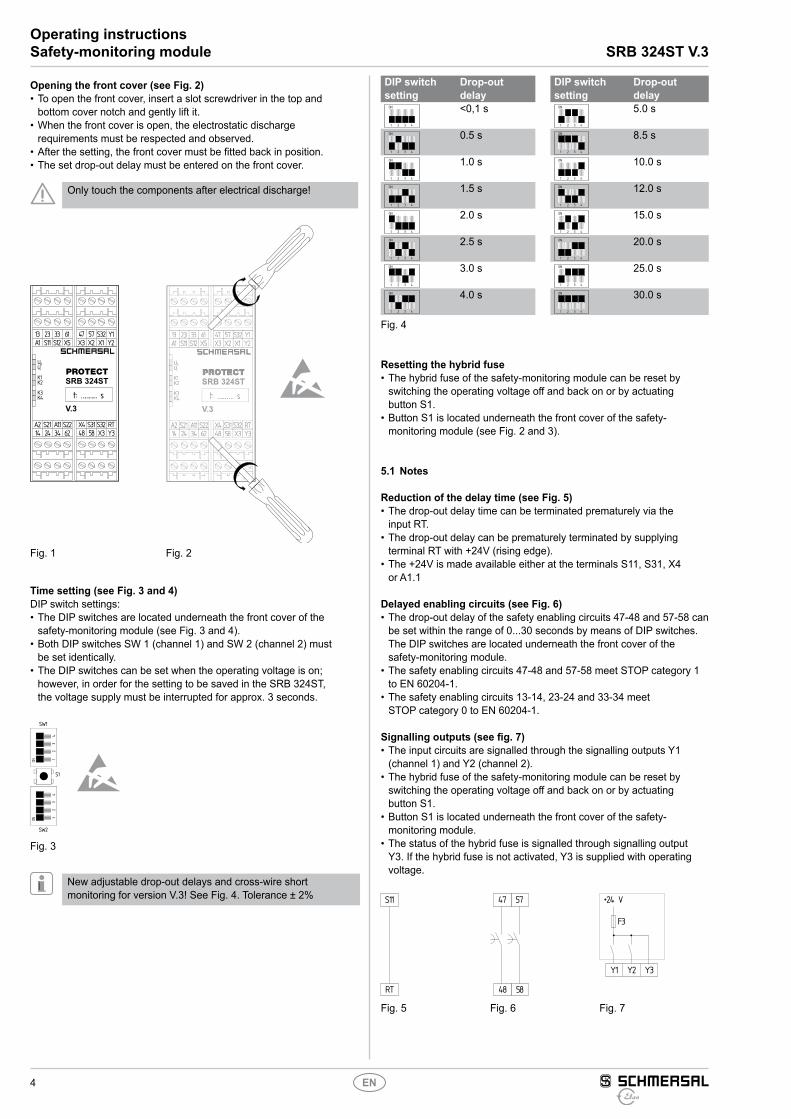
Opening the front cover (see Fig. 2)• To open the front cover, insert a slot screwdriver in the top and
bottom cover notch and gently lift it.• When the front cover is open, the electrostatic discharge
requirements must be respected and observed.• After the setting, the front cover must be fitted back in position.• The set drop-out delay must be entered on the front cover.
Only touch the components after electrical discharge!
UBUi
K1K2
K3K4
13 23 33 61A1 S11 S12 X5
A2 S21 A1.1 S2214 24 34 62
47 57 Y1X3 X1
S32X2 Y2
X4 S32X3
S31 RT48 58 Y3
SRB 324ST
V.3t: ………… s
UBUi
K1K2
K3K4
13 23 33 61A1 S11 S12 X5
A2 S21 A1.1 S2214 24 34 62
47 57 Y1X3 X1
S32X2 Y2
X4 S32X3
S31 RT48 58 Y3
SRB 324ST
V.3t: ………… s
UBUi
K1K2
K3K4
13 23 33 61A1 S11 S12 X5
A2 S21 A1.1 S2214 24 34 62
47 57 Y1X3 X1
S32X2 Y2
X4 S32X3
S31 RT48 58 Y3
SRB 324ST
V.3t: ………… s
Fig. 1 Fig. 2
Time setting (see Fig. 3 and 4)DIP switch settings:• The DIP switches are located underneath the front cover of the
safety-monitoring module (see Fig. 3 and 4).• Both DIP switches SW 1 (channel 1) and SW 2 (channel 2) must
be set identically.• The DIP switches can be set when the operating voltage is on;
however, in order for the setting to be saved in the SRB 324ST, the voltage supply must be interrupted for approx. 3 seconds.
ONON
SW1
SW2
11
22
33
44
S1
Fig. 3
New adjustable drop-out delays and cross-wire short monitoring for version V.3! See Fig. 4. Tolerance ± 2%
DIP switch setting
Drop-out delay
DIP switch setting
Drop-out delay
ON
1 2 3 4
<0,1 s ON
1 2 3 4
5.0 s
ON
1 2 3 4
0.5 s ON
1 2 3 4
8.5 s
ON
1 2 3 4
1.0 s ON
1 2 3 4
10.0 s
ON
1 2 3 4
1.5 s ON
1 2 3 4
12.0 s
ON
1 2 3 4
2.0 s ON
1 2 3 4
15.0 s
ON
1 2 3 4
2.5 s ON
1 2 3 4
20.0 s
ON
1 2 3 4
3.0 s ON
1 2 3 4
25.0 s
ON
1 2 3 4
4.0 s ON
1 2 3 4
30.0 s
Fig. 4
Resetting the hybrid fuse• The hybrid fuse of the safety-monitoring module can be reset by
switching the operating voltage off and back on or by actuating button S1.
• Button S1 is located underneath the front cover of the safety- monitoring module (see Fig. 2 and 3).
5.1 Notes
Reduction of the delay time (see Fig. 5)• The drop-out delay time can be terminated prematurely via the
input RT.• The drop-out delay can be prematurely terminated by supplying
terminal RT with +24V (rising edge).• The +24V is made available either at the terminals S11, S31, X4
or A1.1
Delayed enabling circuits (see Fig. 6)• The drop-out delay of the safety enabling circuits 47-48 and 57-58 can
be set within the range of 0...30 seconds by means of DIP switches. The DIP switches are located underneath the front cover of the safety-monitoring module.
• The safety enabling circuits 47-48 and 57-58 meet STOP category 1 to EN 60204-1.
• The safety enabling circuits 13-14, 23-24 and 33-34 meet STOP category 0 to EN 60204-1.
Signalling outputs (see fig. 7)• The input circuits are signalled through the signalling outputs Y1
(channel 1) and Y2 (channel 2).• The hybrid fuse of the safety-monitoring module can be reset by
switching the operating voltage off and back on or by actuating button S1.
• Button S1 is located underneath the front cover of the safety- monitoring module.
• The status of the hybrid fuse is signalled through signalling output Y3. If the hybrid fuse is not activated, Y3 is supplied with operating voltage.
RT
S11
48
47
58
57 +24 V
F3
Y3Y2Y1
Fig. 5 Fig. 6 Fig. 7
5
SRB 324ST V.3Operating instructionsSafety-monitoring module
EN
5.2 Setting report SRB 324ST V.3This report regarding the setting of the device must be completed accordingly by the customer and enclosed in the technical manual of the machine.
The setting report must be available whenever a safety check is performed.
Company:
The safety-monitoring module is used in the following machine:
Machine n° Machine type Module n°
Set drop-out delay:
Set on (date) Signature of the responsible person
6 Set-up and maintenance
6.1 Functional testingThe safety function of the safety-monitoring module must be tested. The following conditions must be previously checked and met:1. Correct fixing2. Check the integrity of the cable entry and connections3. Check the safety-monitoring module's enclosure for damage.4. Check the electrical function of the connected sensors and
their influence on the safety-monitoring module and the downstream actuators
6.2 MaintenanceA regular visual inspection and functional test, including the following steps, is recommended:1. Check the correct fixing of the safety-monitoring module2. Check the cable for damages3. Check electrical function
Damaged or defective components must be replaced.
7 Disassembly and disposal
7.1 DisassemblyThe safety-monitoring module must be disassembled in a de-energised condition only.
7.2 DisposalThe safety-monitoring module must be disposed of in an appropriate manner in accordance with the national prescriptions and legislations.
8 Appendix
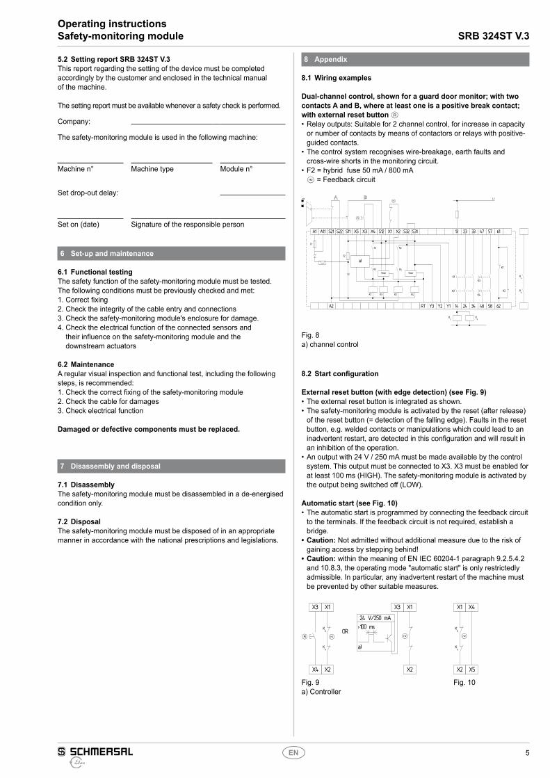
8.1 Wiring examples
Dual-channel control, shown for a guard door monitor; with two contacts A and B, where at least one is a positive break contact; with external reset button J• Relay outputs: Suitable for 2 channel control, for increase in capacity
or number of contacts by means of contactors or relays with positive-guided contacts.
• The control system recognises wire-breakage, earth faults and cross-wire shorts in the monitoring circuit.
• F2 = hybrid fuse 50 mA / 800 mA• S = Feedback circuit
A1 A1.1 S21 S22 S11 X5
J
X3 X4 S12 X1 X2 S32 S31 13 23 33 47
L1
57
K2
K1
K4
KA
KB
K3
KB
KA
K2
K1
61
A2 14 24 34 48RT Y3 Y2 Y1 58 62
S
Timer Timer
K4K2
K2
a)
K3
K4K3
K1
K1
F2
F1
Fig. 8 a) channel control
8.2 Start configuration
External reset button (with edge detection) (see Fig. 9)• The external reset button is integrated as shown.• The safety-monitoring module is activated by the reset (after release)
of the reset button (= detection of the falling edge). Faults in the reset button, e.g. welded contacts or manipulations which could lead to an inadvertent restart, are detected in this configuration and will result in an inhibition of the operation.
• An output with 24 V / 250 mA must be made available by the control system. This output must be connected to X3. X3 must be enabled for at least 100 ms (HIGH). The safety-monitoring module is activated by the output being switched off (LOW).
Automatic start (see Fig. 10)• The automatic start is programmed by connecting the feedback circuit
to the terminals. If the feedback circuit is not required, establish a bridge.
• Caution: Not admitted without additional measure due to the risk of gaining access by stepping behind!
• Caution: within the meaning of EN IEC 60204-1 paragraph 9.2.5.4.2 and 10.8.3, the operating mode "automatic start" is only restrictedly admissible. In particular, any inadvertent restart of the machine must be prevented by other suitable measures.
X4
J S
X3
OR
X2
X1
S
X3
24 V/250 mA>100 ms
a)
X2
X1
KB
KA
X2
S
X1
KB
KA
X5
X4
Fig. 9 a) Controller
Fig. 10
6
Operating instructionsSafety-monitoring module SRB 324ST V.3
EN
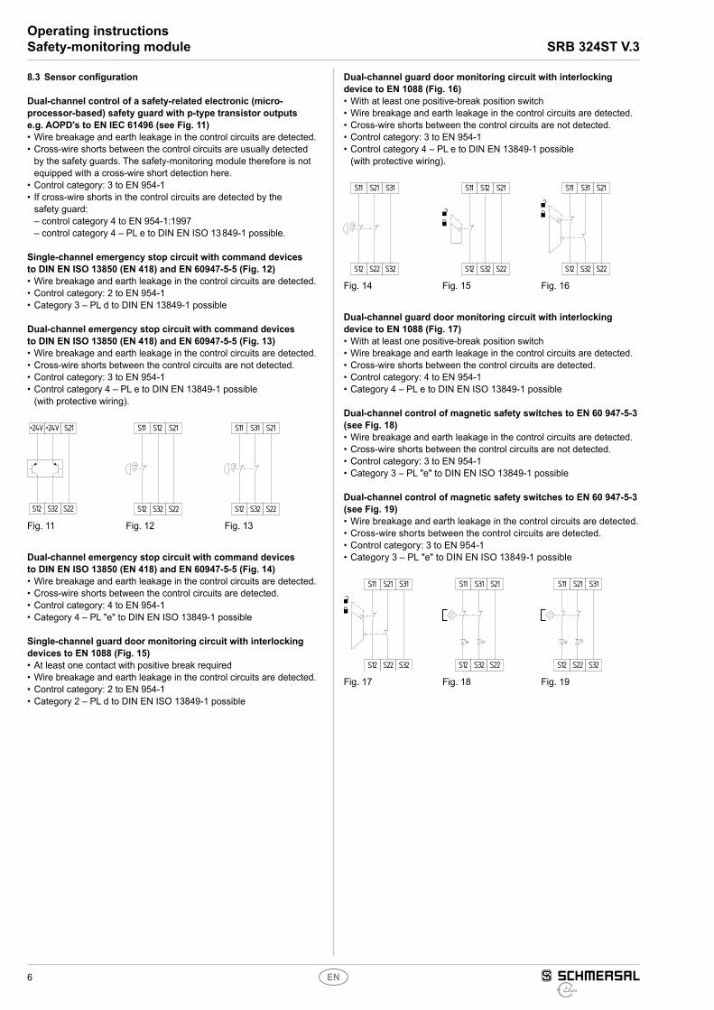
8.3 Sensor configuration
Dual-channel control of a safety-related electronic (micro-processor-based) safety guard with p-type transistor outputs e.g. AOPD's to EN IEC 61496 (see Fig. 11)• Wire breakage and earth leakage in the control circuits are detected.• Cross-wire shorts between the control circuits are usually detected
by the safety guards. The safety-monitoring module therefore is not equipped with a cross-wire short detection here.
• Control category: 3 to EN 954-1• If cross-wire shorts in the control circuits are detected by the
safety guard: – control category 4 to EN 954-1:1997 – control category 4 – PL e to DIN EN ISO 13 849-1 possible.
Single-channel emergency stop circuit with command devices to DIN EN ISO 13850 (EN 418) and EN 60947-5-5 (Fig. 12)• Wire breakage and earth leakage in the control circuits are detected.• Control category: 2 to EN 954-1• Category 3 – PL d to DIN EN 13849-1 possible
Dual-channel emergency stop circuit with command devices to DIN EN ISO 13850 (EN 418) and EN 60947-5-5 (Fig. 13)• Wire breakage and earth leakage in the control circuits are detected.• Cross-wire shorts between the control circuits are not detected.• Control category: 3 to EN 954-1• Control category 4 – PL e to DIN EN 13849-1 possible
(with protective wiring).
S12
+24V
S32
+24V
S22
S21
S12
S11
S32
S12
S22
S21
S12
S11
S32
S31
S22
S21
Fig. 11 Fig. 12 Fig. 13
Dual-channel emergency stop circuit with command devices to DIN EN ISO 13850 (EN 418) and EN 60947-5-5 (Fig. 14)• Wire breakage and earth leakage in the control circuits are detected.• Cross-wire shorts between the control circuits are detected.• Control category: 4 to EN 954-1• Category 4 – PL "e" to DIN EN ISO 13849-1 possible
Single-channel guard door monitoring circuit with interlocking devices to EN 1088 (Fig. 15)• At least one contact with positive break required• Wire breakage and earth leakage in the control circuits are detected.• Control category: 2 to EN 954-1• Category 2 – PL d to DIN EN ISO 13849-1 possible
Dual-channel guard door monitoring circuit with interlocking device to EN 1088 (Fig. 16)• With at least one positive-break position switch• Wire breakage and earth leakage in the control circuits are detected.• Cross-wire shorts between the control circuits are not detected.• Control category: 3 to EN 954-1• Control category 4 – PL e to DIN EN 13849-1 possible
(with protective wiring).
S12
S11
S22
S21
S32
S31
S12
S11
S32
S12
S22
S21
S12
S11
S32
S31
S22
S21
Fig. 14 Fig. 15 Fig. 16
Dual-channel guard door monitoring circuit with interlocking device to EN 1088 (Fig. 17)• With at least one positive-break position switch• Wire breakage and earth leakage in the control circuits are detected.• Cross-wire shorts between the control circuits are detected.• Control category: 4 to EN 954-1• Category 4 – PL e to DIN EN ISO 13849-1 possible
Dual-channel control of magnetic safety switches to EN 60 947-5-3 (see Fig. 18)• Wire breakage and earth leakage in the control circuits are detected.• Cross-wire shorts between the control circuits are not detected.• Control category: 3 to EN 954-1• Category 3 – PL "e" to DIN EN ISO 13849-1 possible
Dual-channel control of magnetic safety switches to EN 60 947-5-3 (see Fig. 19)• Wire breakage and earth leakage in the control circuits are detected.• Cross-wire shorts between the control circuits are detected.• Control category: 3 to EN 954-1• Category 3 – PL "e" to DIN EN ISO 13849-1 possible
S12
S11
S22
S21
S32
S31
S32
S31
S12
S11
S22
S21
S22
S21
S12
S11
S32
S31
Fig. 17 Fig. 18 Fig. 19
7
SRB 324ST V.3Operating instructionsSafety-monitoring module
EN
The connection of magnetic safety switches to the SRB 324ST safety-monitoring module is only admitted when the requirements of the standard EN 60 947-5-3 are observed.
As the technical data are regarded, the following minimum requirements must be met: – switching capacity: min. 240 mW – switching voltage: min. 24 VDC – switching current: min. 10 mA
For example, the following safety sensors meet the requirements: – BNS 33-02z-2187, BNS 33-02zG-2187 – BNS 260-02z, BNS 260-02zG – BNS 260-02-01z, BNS 260-02-01zG
When sensors with LED are wired in the control circuit (protective circuit), the following rated operating voltage must be observed and respected:– 24 VDC with a max. tolerance of –5 %/+20 %– 24 VAC with a max. tolerance of –5 %/+10 %
Otherwise availability problems could occur, especially in series-wired sensors, where a voltage drop in the control circuit is triggered by LED‘s for instance.
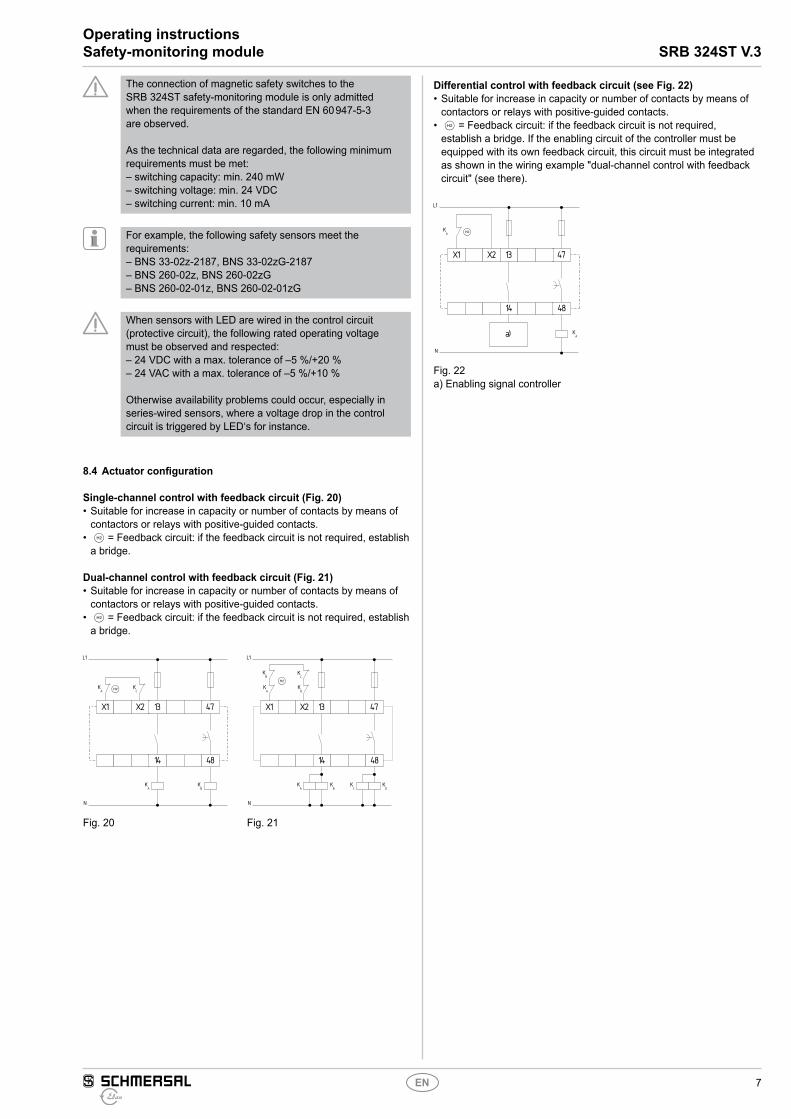
8.4 Actuator configuration
Single-channel control with feedback circuit (Fig. 20)• Suitable for increase in capacity or number of contacts by means of
contactors or relays with positive-guided contacts.• S = Feedback circuit: if the feedback circuit is not required, establish
a bridge.
Dual-channel control with feedback circuit (Fig. 21)• Suitable for increase in capacity or number of contacts by means of
contactors or relays with positive-guided contacts.• S = Feedback circuit: if the feedback circuit is not required, establish
a bridge.
X1 X2 4713
4814
KB
KA S
L1
N
KA
KC
X1 X2 4713
4814
KB
KC
KD
KA
KB
L1
N
KA
KD
KC
S
Fig. 20 Fig. 21
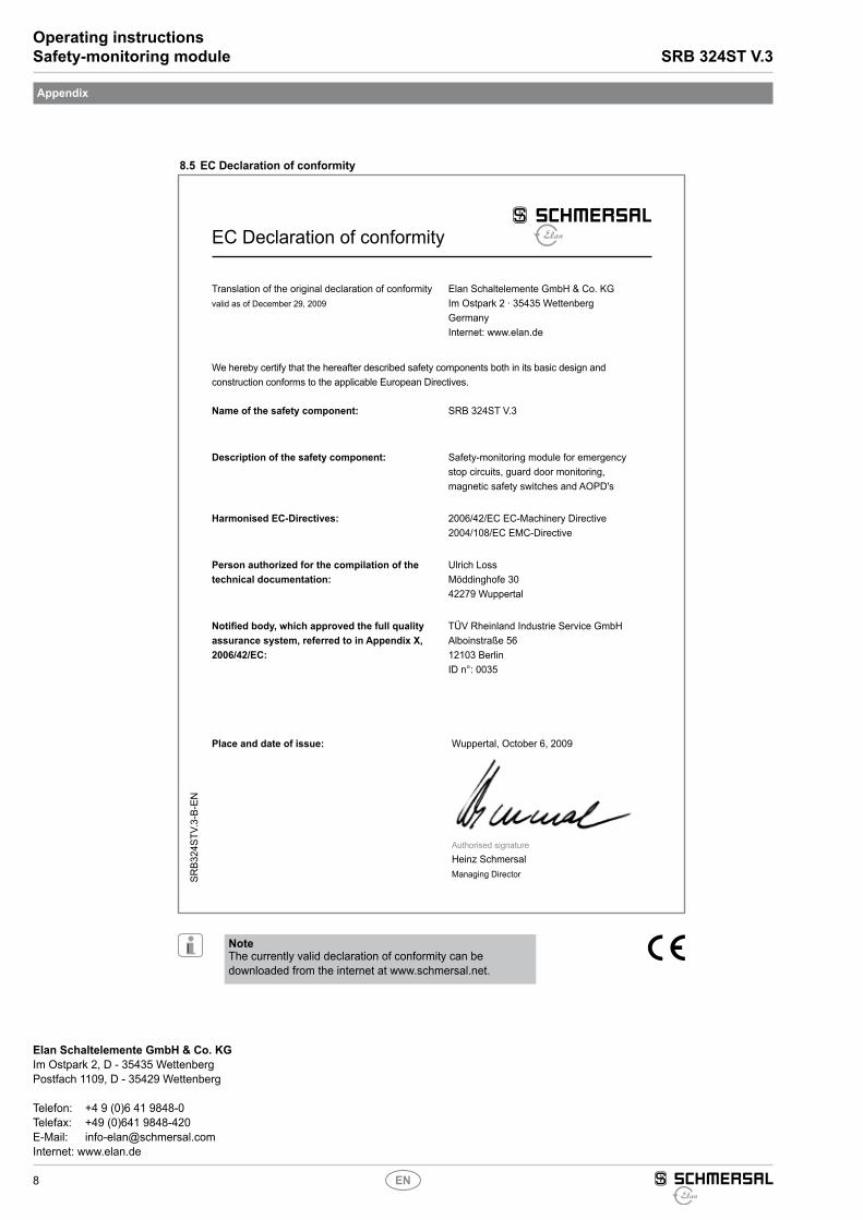
Differential control with feedback circuit (see Fig. 22)• Suitable for increase in capacity or number of contacts by means of
contactors or relays with positive-guided contacts.• S = Feedback circuit: if the feedback circuit is not required,
establish a bridge. If the enabling circuit of the controller must be equipped with its own feedback circuit, this circuit must be integrated as shown in the wiring example "dual-channel control with feedback circuit" (see there).
X1 X2 4713
4814
KA
L1
N
KA
S
a)
Fig. 22a) Enabling signal controller
8
Operating instructionsSafety-monitoring module SRB 324ST V.3
EN
SRB3
24ST
V.3-
B-EN
Elan Schaltelemente GmbH & Co. KGIm Ostpark 2, D - 35435 WettenbergPostfach 1109, D - 35429 Wettenberg
Telefon: +4 9 (0)6 41 9848-0Telefax: +49 (0)641 9848-420E-Mail: [email protected]: www.elan.de
Appendix
8.5 EC Declaration of conformity
NoteThe currently valid declaration of conformity can be downloaded from the internet at www.schmersal.net.
EC Declaration of conformity
Translation of the original declaration of conformityvalid as of December 29, 2009
Elan Schaltelemente GmbH & Co. KGIm Ostpark 2 · 35435 WettenbergGermanyInternet: www.elan.de
We hereby certify that the hereafter described safety components both in its basic design and construction conforms to the applicable European Directives.
Place and date of issue: Wuppertal, October 6, 2009
Authorised signature
Heinz SchmersalManaging Director
Name of the safety component: SRB 324ST V.3
Description of the safety component: Safety-monitoring module for emergency stop circuits, guard door monitoring, magnetic safety switches and AOPD's
Harmonised EC-Directives: 2006/42/EC EC-Machinery Directive2004/108/EC EMC-Directive
Person authorized for the compilation of the technical documentation:
Ulrich LossMöddinghofe 3042279 Wuppertal
Notified body, which approved the full quality assurance system, referred to in Appendix X, 2006/42/EC:
TÜV Rheinland Industrie Service GmbHAlboinstraße 5612103 BerlinID n°: 0035


![MM420 Operating Instructions English [Release A1]docs-europe.electrocomponents.com/webdocs/0391/0900766b8039156… · contents is not permitted unless authorized in writing. ... descriptions](https://img.pdfslide.us/doc/110x75/5b150f387f8b9a7d068d6993/mm420-operating-instructions-english-release-a1docs-contents-is-not-permitted.jpg)


![Untitled Document [docs-europe.electrocomponents.com]docs-europe.electrocomponents.com/webdocs/0920/0900766b809201d… · Schneider Electric Brands ZELIO-CONTROL Measurement Relays](https://img.pdfslide.us/doc/110x75/5abeae277f8b9a5d718d478e/untitled-document-docs-docs-schneider-electric-brands-zelio-control-measurement.jpg)