Embed Size (px)
Citation preview

Operating Instructions
Process pressure transmitter IPT-2x
Process pressure transmitter IPT-2x
Slave for electronic differential pressureMetallic sensor

2
Contents
WIKA Operating Instructions - Process pressure transmitter IPT-2x
Contents1 About this document ............................................................................................................... 4
1.1 Function ........................................................................................................................... 41.2 Target group ..................................................................................................................... 41.3 Symbols used................................................................................................................... 4
2 For your safety ......................................................................................................................... 52.1 Authorised personnel ....................................................................................................... 52.2 Appropriate use ................................................................................................................ 52.3 Warning about incorrect use ............................................................................................. 52.4 General safety instructions ............................................................................................... 52.5 EU conformity ................................................................................................................... 52.6 Installation and operation in the USA and Canada ........................................................... 6
3 Product description ................................................................................................................. 73.1 Configuration .................................................................................................................... 73.2 Principle of operation........................................................................................................ 83.3 Supplementary cleaning procedures .............................................................................. 113.4 Packaging, transport and storage ................................................................................... 12
4 Mounting ................................................................................................................................. 134.1 General instructions ....................................................................................................... 134.2 Ventilation and pressure compensation .......................................................................... 154.3 Combination Master - Slave ........................................................................................... 174.4 Level measurement ........................................................................................................ 184.5 Differential pressure measurement ................................................................................ 194.6 Interface measurement .................................................................................................. 194.7 Density measurement .................................................................................................... 204.8 Density-compensated level measurement ..................................................................... 214.9 External housing ............................................................................................................ 23
5 Connecting to power supply ................................................................................................. 245.1 Preparing the connection ............................................................................................... 245.2 Connecting ..................................................................................................................... 245.3 Single chamber housing ................................................................................................. 265.4 External housing with version IP68 (25 bar) ................................................................... 265.5 Connection example ...................................................................................................... 28
6 Set up with the display and adjustment module ................................................................ 296.1 Parameter adjustment - Extended adjustment................................................................ 29
7 Diagnosis, asset management and service ........................................................................ 427.1 Maintenance .................................................................................................................. 427.2 Rectify faults ................................................................................................................... 427.3 Exchange process module on version IP68 (25 bar) ...................................................... 427.4 Exchanging the electronics module ................................................................................ 437.5 Instrument repair ............................................................................................................ 43
8 Dismount................................................................................................................................. 458.1 Dismounting steps.......................................................................................................... 458.2 Disposal ......................................................................................................................... 45
9 Supplement ............................................................................................................................ 469.1 Technical data ................................................................................................................ 46

3
Contents
WIKA Operating Instructions - Process pressure transmitter IPT-2x
9.2 Calculation of the total deviation ..................................................................................... 599.3 Practical example ........................................................................................................... 609.4 Dimensions .................................................................................................................... 639.5 Trademark ...................................................................................................................... 71
Safety instructions for Ex areasTake note of the Ex specific safety instructions for Ex applications. These instructions are attached as documents to each instrument with Ex approval and are part of the operating instructions.
Editing status: 2020-05-12

4
1 About this document
WIKA Operating Instructions - Process pressure transmitter IPT-2x
1 About this document
1.1 FunctionThis instruction provides all the information you need for mounting, connection and setup as well as important instructions for mainte-nance, fault rectification, the exchange of parts and the safety of the user. Please read this information before putting the instrument into operation and keep this manual accessible in the immediate vicinity of the device.
1.2 Target groupThis operating instructions manual is directed to trained personnel. The contents of this manual must be made available to the qualified personnel and implemented.
1.3 Symbols usedInformation, note, tip: This symbol indicates helpful additional infor-mation and tips for successful work.Note: This symbol indicates notes to prevent failures, malfunctions, damage to devices or plants.Caution: Non-observance of the information marked with this symbol may result in personal injury.Warning: Non-observance of the information marked with this symbol may result in serious or fatal personal injury.Danger: Non-observance of the information marked with this symbol results in serious or fatal personal injury.
Ex applicationsThis symbol indicates special instructions for Ex applications.
• ListThe dot set in front indicates a list with no implied sequence.
1 Sequence of actionsNumbers set in front indicate successive steps in a procedure.
Battery disposalThis symbol indicates special information about the disposal of bat-teries and accumulators.

5
2 For your safety
WIKA Operating Instructions - Process pressure transmitter IPT-2x
2 For your safety
2.1 Authorised personnelAll operations described in this documentation must be carried out only by trained, qualified personnel authorised by the plant operator.During work on and with the device, the required personal protective equipment must always be worn.
2.2 Appropriate useIPT-2x is a slave sensor for electronic differential pressure measure-ment.You can find detailed information about the area of application in chapter "Product description".Operational reliability is ensured only if the instrument is properly used according to the specifications in the operating instructions manual as well as possible supplementary instructions.
2.3 Warning about incorrect useInappropriate or incorrect use of this product can give rise to applica-tion-specific hazards, e.g. vessel overfill through incorrect mounting or adjustment. Damage to property and persons or environmental contamination can result. Also, the protective characteristics of the instrument can be impaired.
2.4 General safety instructionsThis is a state-of-the-art instrument complying with all prevailing regulations and directives. The instrument must only be operated in a technically flawless and reliable condition. The operator is responsi-ble for the trouble-free operation of the instrument. When measuring aggressive or corrosive media that can cause a dangerous situation if the instrument malfunctions, the operator has to implement suitable measures to make sure the instrument is functioning properly.The safety instructions in this operating instructions manual, the na-tional installation standards as well as the valid safety regulations and accident prevention rules must be observed by the user.For safety and warranty reasons, any invasive work on the device beyond that described in the operating instructions manual may be carried out only by personnel authorised by the manufacturer. Arbi-trary conversions or modifications are explicitly forbidden. For safety reasons, only the accessory specified by the manufacturer must be used.To avoid any danger, the safety approval markings and safety tips on the device must also be observed.
2.5 EU conformityThe device fulfils the legal requirements of the applicable EU direc-tives. By affixing the CE marking, we confirm the conformity of the instrument with these directives.

6
2 For your safety
WIKA Operating Instructions - Process pressure transmitter IPT-2x
The EU conformity declaration can be found on our homepage.Due to the design of its process fittings, the device does not subject of EU pressure device directive if it is operated at process pressures ≤ 200 bar.1)
2.6 Installation and operation in the USA and Canada
This information is only valid for USA and Canada. Hence the follow-ing text is only available in the English language.Installations in the US shall comply with the relevant requirements of the National Electrical Code (ANSI/NFPA 70).Installations in Canada shall comply with the relevant requirements of the Canadian Electrical Code.
1) Exception: Versions with measuring ranges from 250 bar. These are subject of the EU Pressure Device Directive.

7
3 Product description
WIKA Operating Instructions - Process pressure transmitter IPT-2x
3 Product description
3.1 ConfigurationThe scope of delivery encompasses:
• Pressure transmitter IPT-2x - Slave sensor• Ready-made connection cable, unassembled cable gland
The further scope of delivery encompasses:
• Documentation – Quick setup guide IPT-2x – Test certificate for pressure transmitters – Instructions for optional instrument features – Ex-specific "Safety instructions" (with Ex versions) – If necessary, further certificates
Information:Optional instrument features are also described in this operating instructions manual. The respective scope of delivery results from the order specification.
This operating instructions manual applies to the following instrument versions:
• Hardware from 1.0.0• Software version from 1.0.0
Note:You can find the hardware and software version of the instrument as follows:
• On the type plate of the electronics module• In the adjustment menu under "Info"
The type label contains the most important data for identification and use of the instrument:
Scope of delivery
Scope of this operating instructions
Type label

8
3 Product description
WIKA Operating Instructions - Process pressure transmitter IPT-2x
1
5
6
7
4
2
3MWP :
Fig. 1: Layout of the type label (example)1 Instrument type2 Field for approvals3 Technical data4 Product code5 Serial number of the instrument6 Symbol of the device protection class7 ID numbers, instrument documentation
3.2 Principle of operationIPT-2x is suitable for applications in virtually all industries. It is used for the measurement of the following pressure types.
• Gauge pressure• Absolute pressure• Vacuum
Measured products are gases, vapours and liquids.The device is especially suitable for applications with higher tempera-tures and high pressures.
The electronic differential pressure measurement is suitable for the measurement of the following process variables:
• Level• Flow• Differential pressure• Density• Interface• Level, density-compensated
The IPT-2x slave sensor is combined with a sensor from the instru-ment series for electronic differential pressure measurement.
Application area
Measured products
Measured variables
Electronicdifferentialpressure

9
3 Product description
WIKA Operating Instructions - Process pressure transmitter IPT-2x
1
2
Fig. 2: Example, electronic differential pressure for level measurement in pres-surized vessel1 IPT-2x2 IPT-2x, slave sensor
The sensors are connected via a screened four-wire cable. The measured value from the slave sensor is read in and factored into the calculations. Power supply and parameter adjustment are carried out through the master sensor.
Information:The sensor versions "Relative pressure climate-compensated" as well as "Double chamber housing" are not suitable for connection of a slave sensor.
You can find further information in chapter "Combination Master - Slave " of this operating instructions.
The process pressure acts on the sensor element via the process dia-phragm. The process pressure causes a resistance change which is converted into a corresponding output signal and output as measured value.
Piezoresistive sensor elementMeasuring ranges up to 40 bar: piezoresistive sensor element with internal transmission liquid is used.
Measuring system

10
3 Product description
WIKA Operating Instructions - Process pressure transmitter IPT-2x
1
3 4
2
Fig. 3: Configuration of the measuring system with piezoresistive sensor ele-ment1 Sensor element2 Base element3 Transmission liquid4 Process diaphragm
Strain gauge (DMS) sensor elementFor measuring ranges above 100 bar, a strain gauge (DMS) sensor element (dry system) is used.
1
2
3Fig. 4: Configuration of the measuring system with strain gauge (DMS) sensor element1 Sensor element2 Process diaphragm3 Pressure cylinder
Ceramic/metallic measuring cellWith small measuring ranges ≤ 400 mbar or higher temperature ranges, the ceramic/metallic measuring cell is the measuring unit. It consists of the ceramic-capacitive measuring cell and a special, temperature-compensated chemical seal system.

11
3 Product description
WIKA Operating Instructions - Process pressure transmitter IPT-2x
4321Fig. 5: Configuration of the ceramic/metallic measuring cell1 Process diaphragm2 Isolating liquid3 FeNi adapter4 Ceramic-capacitive measuring cell
Relative pressure: the measuring cell is open to the atmosphere. The ambient pressure is detected in the measuring cell and compen-sated. It thus has no influence on the measured value.Absolute pressure: the measuring cell contains vacuum and is encapsulated. The ambient pressure is not compensated and does hence influence the measured value.
The measuring system is completely welded and thus sealed against the process.The process fitting is sealed against the process by a suitable seal. It must be provided by the customer, depending on the process fitting also included in the scope of delivery, see chapter "Technical data", "Materials and weights".
3.3 Supplementary cleaning proceduresThe IPT-2x is also available in the version "Oil, grease and silicone-free". These instruments have passed through a special cleaning procedure to remove oil, grease and paint-wetting impairment sub-stances (PWIS).The cleaning is carried out on all wetted parts as well as on surfaces accessible from outside. To keep the purity level, the instruments are immediately packed in plastic foil after the cleaning process. The purity level remains as long as the instrument is kept in the closed original packaging.
Caution:The IPT-2x in this version may not be used in oxygen applications. For this purpose, instruments are available in the special version "Oil, grease and silicone-free for oxygen applications".
Pressure types
Seal concept

12
3 Product description
WIKA Operating Instructions - Process pressure transmitter IPT-2x
3.4 Packaging, transport and storageYour instrument was protected by packaging during transport. Its capacity to handle normal loads during transport is assured by a test based on ISO 4180.The packaging consists of environment-friendly, recyclable card-board. For special versions, PE foam or PE foil is also used. Dispose of the packaging material via specialised recycling companies.
Transport must be carried out in due consideration of the notes on the transport packaging. Nonobservance of these instructions can cause damage to the device.
The delivery must be checked for completeness and possible transit damage immediately at receipt. Ascertained transit damage or con-cealed defects must be appropriately dealt with.
Up to the time of installation, the packages must be left closed and stored according to the orientation and storage markings on the outside.Unless otherwise indicated, the packages must be stored only under the following conditions:
• Not in the open• Dry and dust free• Not exposed to corrosive media• Protected against solar radiation• Avoiding mechanical shock and vibration
• Storage and transport temperature see chapter "Supplement - Technical data - Ambient conditions"
• Relative humidity 20 … 85 %
With instrument weights of more than 18 kg (39.68 lbs) suitable and approved equipment must be used for lifting and carrying.
Packaging
Transport
Transport inspection
Storage
Storage and transport temperature
Lifting and carrying

13
4 Mounting
WIKA Operating Instructions - Process pressure transmitter IPT-2x
4 Mounting
4.1 General instructionsNote:For safety reasons, the instrument must only be operated within the permissible process conditions. You can find detailed information on the process conditions in chapter "Technical data" of the operating instructions or on the type label.
Hence make sure before mounting that all parts of the instrument ex-posed to the process are suitable for the existing process conditions.These are mainly:
• Active measuring component• Process fitting• Process seal
Process conditions in particular are:
• Process pressure• Process temperature• Chemical properties of the medium• Abrasion and mechanical influences
Protect your instrument against moisture ingress through the following measures:
• Use a suitable connection cable (see chapter "Connecting to power supply")
• Tighten the cable gland or plug connector• Lead the connection cable downward in front of the cable entry or
plug connector
This applies mainly to outdoor installations, in areas where high humidity is expected (e.g. through cleaning processes) and on cooled or heated vessels.
Note:Make sure that the degree of contamination specified in chapter "Technical data" meets the existing ambient conditions.
Note:Make sure that during installation or maintenance no moisture or dirt can get inside the instrument.To maintain the housing protection, make sure that the housing lid is closed during operation and locked, if necessary.
Devices with threaded fitting are screwed into the process fitting with a suitable wrench via the hexagon.See chapter "Dimensions" for wrench size.
Process conditions
Protection against mois-ture
Screwing in

14
4 Mounting
WIKA Operating Instructions - Process pressure transmitter IPT-2x
Warning:The housing or the electrical connection may not be used for screw-ing in! Depending on the device version, tightening can cause dam-age, e. g. to the rotation mechanism of the housing.
If there is strong vibration at the mounting location, the instrument version with external housing should be used. See chapter "External housing".
The permissible process pressure range is specified by "MWP" (Maxi-mum Working Pressure) on the type label, see chapter "Structure". The MWP takes the element of the measuring cell and processing fitting combination with the weakest pressure into consideration and may applied permanently. The specification refers to a reference temperature of +20 °C (+68 °F). It also applies when a measuring cell with a higher measuring range than the permissible pressure range of the process fitting is installed order-related.In order to prevent damage to the device, a test pressure may only exceed the specified MWP briefly by 1.5 times at reference tempera-ture. The pressure stage of the process fitting as well as the overload resistance of the measuring cell are taken into consideration here (see chapter "Technical Data").In addition, a temperature derating of the process fitting, e. g. with flanges, can limit the permissible process pressure range according to the respective standard.
The permissible process pressure range is stated on the type label. The instrument should only be operated with these pressures if the mounting accessory used also fulfils these values. This should be en-sured by suitable flanges, welded sockets, tension rings with Clamp connections, sealings, etc.
Higher process temperatures often mean also higher ambient temperatures. Make sure that the upper temperature limits stated in chapter "Technical data" for the environment of the electronics hous-ing and connection cable are not exceeded.
1
2
Fig. 6: Temperature ranges1 Process temperature2 Ambient temperature
Vibrations
Permissible process pressure (MWP) - Device
Permissible process pressure (MWP) - Mount-ing accessory
Temperature limits

15
4 Mounting
WIKA Operating Instructions - Process pressure transmitter IPT-2x
4.2 Ventilation and pressure compensationThe filter element in the electronics housing has the following func-tions:
• Ventilation of the electronics housing• Atmospheric pressure compensation (with relative pressure meas-
uring ranges)
Caution:The filter element causes a time-delayed pressure compensation. When quickly opening/closing the housing cover, the measured value can change for approx. 5 s by up to 15 mbar.
For an effective ventilation, the filter element must be always free from buildup. In case of horizontal mounting, turn the housing so that the filter element points downward after the instrument is installed. This provides better protection against buildup.
Caution:Do not use a high-pressure cleaner. The filter element could be dam-aged, which would allow moisture into the housing.
The following paragraphs describe how the filter element is arranged in the different instrument versions.
1 2 3
4 4 4
Fig. 7: Position of the filter element - non-Ex, Ex-ia version1 Plastic, stainless steel housing (precision casting)2 Aluminium housing3 Stainless steel housing (electropolished)4 Filter element
With the following instruments a blind plug is installed instead of the filter element:
• Instruments in protection IP66/IP68 (1 bar) - ventilation via capillar-ies in non-detachable cable
• Instruments with absolute pressure
→ Turn the metal ring in such a way that the filter element points downward after installation of the instrument. This provides better protection against buildup.
Filter element - Function
Filter element - Position
Filter element - Position Ex-d version

16
4 Mounting
WIKA Operating Instructions - Process pressure transmitter IPT-2x
1
2
Fig. 8: Position of the filter element - Ex-d version1 Rotatable metal ring2 Filter element
Instruments with absolute pressure have a blind plug mounted instead of the filter element.
The process assembly of instruments with Second Line of Defense (gastight leadthrough) is completely encapsulated. An absolute pres-sure measuring cell is used so that no ventilation is required.
1
2
Fig. 9: Position of the filter element - gastight leadthrough1 Filter element
1
Fig. 10: Position of the filter element - IP69K version1 Filter element
Instruments with absolute pressure have a blind plug mounted instead of the filter element.
Instruments with Second Line of Defense
Filter element - Position IP69K version

17
4 Mounting
WIKA Operating Instructions - Process pressure transmitter IPT-2x
4.3 Combination Master - SlaveIn principle, any sensor combination within the instrument series is allowed. The following requirements must be fulfilled:
• Configuration, Master sensor suitable for electronic differential pressure
• Pressure type is identical for both sensors, i.e. relative pressure/relative pressure or absolute pressure/absolute pressure
• Master sensor measures the higher pressure• Measurement setup as shown in the following chapters
The measuring range of each sensor is selected such that it fits the measuring loop. For this, the max. recommended turn down must be noted. See chapter "Technical data". It is absolutely necessary the the measuring ranges of Master and Slave correspond.Measurement result = Measured value of Master (total pres-sure) - measured value of Slave (static pressure)Depending on the application, individual combinations can result, see following examples:
DataApplication: Level measurementMedium: WaterVessel height: 12 m, hydrostatic pressure = 12 m x 1000 kg/m3 x 9.81 m/s2 = 117.7 kPa = 1.18 barSuperimposed pressure: 1 barTotal pressure: 1.18 bar + 1 bar = 2.18 bar
Instrument selectionNominal measuring range Master: 2.5 barNominal measuring range Slave: 1 barTurn Down: 2.5 bar/1.18 bar = 2.1 : 1
DataApplication: Level measurementMedium: WaterVessel height: 500 mm, hydrostatic pressure = 0.50 m x 1000 kg/m3 x 9.81 m/s2 = 4.9 kPa = 0.049 barSuperimposed pressure: 350 mbar = 0.35 barTotal pressure: 0.049 bar + 0.35 bar = 0.399 bar
Instrument selectionNominal measuring range Master: 0.4 barNominal measuring range Slave: 0.4 barTurn Down: 0.4 bar /0.049 bar = 8.2 : 1
DataApplication: Differential pressure measurementMedium: GasStatic pressure: 0.8 bar
Example - large vessel
Example - small vessel
Example-orificeinpipeline

18
4 Mounting
WIKA Operating Instructions - Process pressure transmitter IPT-2x
Differential pressure on orifice: 50 mbar = 0.050 barTotal pressure: 0.8 bar + 0.05 bar = 0.85 bar
Instrument selectionNominal measuring range Master: 1 barNominal measuring range Slave: 1 barTurn Down: 1 bar/0.050 bar = 20 : 1
The measuring result (level, pressure difference) as well as meas-ured value Slave (static or superimposed pressure) are output by the sensor. Depending on the instrument version, output as 4 … 20 mA signal or digitally via HART, Profibus PA or Foundation Fieldbus.
4.4 Level measurementThe master/slave combination is suitable for level measurement in a pressurized vesselKeep the following in mind when setting up the measuring system:
• Mount the master sensor below the min. level• Do not mount the master sensor close to the filling stream or
emptying area• Mount the master sensor so that it is protected against pressure
shocks from the stirrer• Mount the slave sensor above the max. level
1
2
Fig. 11: Measurement setup, level measurement in pressurized vessel1 IPT-2x2 IPT-2x, slave sensor
Output measured values
Measurement setup

19
4 Mounting
WIKA Operating Instructions - Process pressure transmitter IPT-2x
4.5 DifferentialpressuremeasurementThe master/slave combination is suitable for differential pressure measurementTake note of the following instructions for the measurement setup, for example in gases:
• Mount the instruments above the measuring point
Possible condensation can then drain off into the process line.
1 2
Fig. 12: Measurement setup for differential pressure measurement of gases in pipelines1 IPT-2x2 IPT-2x, slave sensor
4.6 Interface measurementThe master/slave combination is suitable for interface measurementRequirements for a functioning measurement are:
• Vessel with changing level• Products with steady density• Interface always between the measurement points• Total level always above the upper measurement point
The mounting distance h of the two sensors should be at least 10 %, better 20 %, of the final value of the sensor measuring range. A bigger distance increases the accuracy of the interface measurement.
Measurement setup
Measurement setup

20
4 Mounting
WIKA Operating Instructions - Process pressure transmitter IPT-2x
h1,0
0,8
1
2
Fig. 13: Measurement setup with interface measurement, h = distance between the two measuring points1 IPT-2x2 IPT-2x, slave sensor
The interface measurement is possible in open as well as in closed vessels.
4.7 Density measurement
The master/slave combination is suitable for density measurement.Requirements for a functioning measurement are:
• Vessel with changing level• Distance between the measurement points as large as possible• Level always above the upper measuring point
Measurement setup

21
4 Mounting
WIKA Operating Instructions - Process pressure transmitter IPT-2x
h
1
2
Fig. 14: Measurement setup for density measurement, h = distance between the two measuring points1 IPT-2x2 IPT-2x, slave sensor
The mounting distance h of the two sensors should be at least 10 %, better 20 %, of the final value of the sensor measuring range. A bigger distance increases the accuracy of the density measurement.Slight density changes cause only slight changes of the measured differential pressure. The measuring range must hence be selected accordingly.The density measurement is possible in open as well as in closed vessels.
4.8 Density-compensated level measurementThe master/slave combination is suitable for density-compensated level measurementKeep the following in mind when setting up the measuring system:
• Mount the master sensor below the min. level• Mount the slave sensor above the master sensor• Mount both sensors away from the filling stream and emptying and
protected against pressure shocks from the stirrer
Measurement setup

22
4 Mounting
WIKA Operating Instructions - Process pressure transmitter IPT-2x
h
1
2
Fig. 15: Measurement setup for density-compensated level measurement, h = distance between the two measuring points1 IPT-2x2 IPT-2x, slave sensor
The mounting distance h of the two sensors should be at least 10 %, better 20 %, of the final value of the sensor measuring range. A bigger distance increases the accuracy of the density compensation.The density-compensated level measurement starts with the stored density 1 kg/dm3. As soon as both sensors are covered, this value will be replaced by the calculated density. Density compensation means that the level value in height units and the adjustment values do not change in case of a fluctuating density.The density-compensated level measurement is only possible in open, i.e. unpressurized vessels.

23
4 Mounting
WIKA Operating Instructions - Process pressure transmitter IPT-2x
4.9 External housing
1
2
3
4
5
Fig. 16: Configuration, process module, external housing1 Pipeline2 Process module3 Connection cable process assembly - External housing4 External housing5 Signal cable
Configuration

24
5 Connecting to power supply
WIKA Operating Instructions - Process pressure transmitter IPT-2x
5 Connecting to power supply
5.1 Preparing the connectionAlways keep in mind the following safety instructions:
• Carry out electrical connection by trained, qualified personnel authorised by the plant operator
• If overvoltage surges are expected, overvoltage arresters should be installed
Warning:Only connect or disconnect in de-energized state.
The voltage supply and the signal transmission are carried out via the four-wire, screened connection cable from the master sensor.You can find the data for this signal circuit in chapter "Technical data".
The shielding of the cable between master and slave sensor must be connected on both ends to ground potential. In the sensor, the shielding is connected directly to the internal ground terminal. The ground terminal on the outside of the housing must be connected to the ground potential (low impedance).
Metric threadsIn the case of instrument housings with metric thread, the cable glands are screwed in at the factory. They are sealed with plastic plugs as transport protection.
Note:You have to remove these plugs before electrical connection.
NPT threadIn the case of instrument housings with self-sealing NPT threads, it is not possible to have the cable entries screwed in at the factory. The free openings for the cable glands are therefore covered with red dust protection caps as transport protection.
Note:Prior to setup you have to replace these protective caps with ap-proved cable glands or close the openings with suitable blind plugs.
On plastic housings, the NPT cable gland or the Conduit steel tube must be screwed into the threaded insert without grease.Max. torque for all housings, see chapter "Technical data".
5.2 ConnectingThe connection to the Master sensor is carried out through spring-loaded terminals in the respective housing. For this, use the supplied, confectioned cable. Solid cores as well as flexible cores with cable end sleeves are inserted directly into the terminal openings.
Safety instructions
Voltage supply
Cable screening and grounding
Cable glands
Connection technology

25
5 Connecting to power supply
WIKA Operating Instructions - Process pressure transmitter IPT-2x
In case of flexible cores without end sleeves, press the terminal from above with a small screwdriver, the terminal opening is then free. When the screwdriver is released, the terminal closes again.
Information:The terminal block is pluggable and can be removed from the electronics. To do this, lift the terminal block with a small screwdriver and pull it out. When reinserting the terminal block, you should hear it snap in.
You can find further information on the max. wire cross-section under "Technical data - Electromechanical data".
Proceed as follows:1. Unscrew the housing lid2. Loosen compression nut of the cable gland and remove blind
plug3. Remove approx. 10 cm (4 in) of the cable mantle, strip approx.
1 cm (0.4 in) insulation from the individual wires or use supplied connection cable
4. Insert the cable into the sensor through the cable entry
Fig. 17: Connection steps 5 and 6
5. Insert the wire ends into the terminals according to the wiring plan6. Check the hold of the wires in the terminals by lightly pulling on
them7. Connect the shielding to the internal ground terminal, connect the
external ground terminal to potential equalisation8. Tighten the compression nut of the cable entry gland. The seal
ring must completely encircle the cable9. Unscrew the blind plug on the Master, screw in the supplied cable
gland10. Connection cable to Master, see steps 3 to 811. Screw the housing lid back on
Connection procedure

26
5 Connecting to power supply
WIKA Operating Instructions - Process pressure transmitter IPT-2x
The electrical connection is finished.
5.3 Single chamber housingThe following illustration applies to the non-Ex, Ex-ia and Ex-d-ia version.
5 6 7 8 4
2
1
connect to Master
Fig. 18: Wiring plan IPT-2x Slave sensor1 To the Master sensor2 Ground terminal for connection of the cable screening2)
5.4 External housing with version IP68 (25 bar)
1
23
Fig. 19: IPT-2x in IP68 version 25 bar with axial cable outlet, external housing1 Transmitter2 Connection cable3 External housing
Electronics and connec-tion compartment
Overview
2) Connect shielding here. Connect ground terminal on the outside of the hous-ing to ground as prescribed. The two terminals are galvanically connected.

27
5 Connecting to power supply
WIKA Operating Instructions - Process pressure transmitter IPT-2x
1
2
3
51 2( )+ (-) 6 7 8
4...20mA
Fig. 20: Electronics and connection compartment1 Electronics module2 Cable gland for voltage supply3 Cable gland for connection cable, transmitter
1 2 3 4
63
41
2
5
Fig. 21: Connection of the process component in the housing base1 Yellow2 White3 Red4 Black5 Shielding6 Breather capillaries
Electronics and connec-tion compartment for power supply
Terminal compartment, housing socket

28
5 Connecting to power supply
WIKA Operating Instructions - Process pressure transmitter IPT-2x
5 6 7 8 4
2
1
connect to Master
Fig. 22: Wiring plan IPT-2x Slave sensor1 To the Master sensor2 Ground terminal for connection of the cable screening3)
5.5 Connection example
5 6 7 8
4
2
3
1
4
connect to Master
51 2+( ) (-) 6 7 8
4...20mA
Fig. 23: Connection example, electronic differential pressure1 Master sensor2 Slave sensor3 Connection cable4 Supply and signal circuit, Master sensor
Connection between master and sensor is carried out according to the table:
Master sensor Slave sensor
Terminal 5 Terminal 5
Terminal 6 Terminal 6
Terminal 7 Terminal 7
Terminal 8 Terminal 8
Electronics and connec-tion compartment
Connection example, electronicdifferentialpressure
3) Connect shielding here. Connect ground terminal on the outside of the hous-ing to ground as prescribed. The two terminals are galvanically connected.

29
6 Set up with the display and adjustment module
WIKA Operating Instructions - Process pressure transmitter IPT-2x
6 Set up with the display and adjustment module
6.1 Parameter adjustment - Extended adjustmentFor technically demanding measuring points, you can carry out extended settings in "Extended adjustment".
The main menu is divided into five sections with the following func-tions:
Setup: Settings, e.g., for measurement loop name, application, units, position correction, adjustment, signal outputDisplay: Settings, e.g., for language, measured value display, lightingDiagnosis: Information, e.g. on instrument status, pointer, measure-ment reliability, simulationAdditional adjustments: PIN, date/time, reset, copy functionInfo: Instrument name, hardware and software version, date of manu-facture, sensor featuresIn the main menu item "Setup", the individual submenu items should be selected one after the other and provided with the correct param-eter values.The following submenu points are available:
In the following section, the menu items from the menu "Setup" for electronic differential pressure measurement are described in detail. Depending on the selected application, different sections are relevant.
Information:Further menu items of the menu "Setup" as well as the complete menus "Display", "Diagnosis", "Additional adjustments" and "Info" are described in the operating instructions of the respective master sensor.
6.1.1 SetupIn this menu item you activate/deactivate the slave sensor for elec-tronic differential pressure and select the application.
Main menu
Application

30
6 Set up with the display and adjustment module
WIKA Operating Instructions - Process pressure transmitter IPT-2x
The IPT-2x in conjunction with a slave sensor can be used for flow, differential pressure, density and interface measurement. The default setting is differential pressure measurement. Switchover is carried out in the adjustment menu.If you have connected a slave sensor, you confirm this with "Activate".
Note:It is absolutely necessary to activate the slave sensor to have the applications displayed in the electronic differential pressure measure-ment menus.
Enter the requested parameters via the appropriate keys, save your settings with [OK] and jump to the next menu item with the [ESC] and the [->] key.
In this menu item, you determine the units for the "Min. adjustment/Zero" and "Max. adjustment/Span" as well as the static pressure.
If the level should be adjusted in a height unit, the density of the me-dium must also be entered later during the adjustment.In addition, the unit is determined in the menu item "Peak value temperature".Enter the requested parameters via the appropriate keys, save your settings with [OK] and jump to the next menu item with the [ESC] and the [->] key.
Especially with chemical seal systems, the installation position of the instrument can shift (offset) the measured value. Position correction compensates this offset. In the process, the actual measured value is taken over automatically. With relative pressure measuring cells a manual offset can also be carried out.There are the following possibilities for a position correction with a master/slave combination
• Automatic correction for both sensors• Manual correction for the Master (differential pressure)• Manual correction for the Slave (static pressure)
Units
Position correction

31
6 Set up with the display and adjustment module
WIKA Operating Instructions - Process pressure transmitter IPT-2x
With a master/slave combination in the application "Density-compen-sated level measurement" there are the following additional options for the position correction
• Automatic correction, master (level)• Manual correction for the Master (level)
During an automatic position correction, the current measured value is accepted as the correction value. This value must not be influ-enced/corrupted by product coverage or static pressure.In case of a manual position correction, the offset value is determined by the user. Select for this purpose the function "Edit" and enter the requested value.Save your settings with [OK] and move with [ESC] and [->] to the next menu item.After the position correction is carried out, the actual measured value is corrected to 0. The corrective value appears with an inverse sign as offset value in the display.The position correction can be repeated any number of times.
IPT-2x always measures pressure independently of the process vari-able selected in the menu item "Application". To output the selected process variable correctly, an allocation of the output signal to 0 % and 100 % must be carried out (adjustment).With the application "Level", the hydrostatic pressure, e.g. with full and empty vessel, is entered for adjustment. A superimposed pres-sure is detected by the slave sensor and automatically compensated. See the following example:
Adjustment

32
6 Set up with the display and adjustment module
WIKA Operating Instructions - Process pressure transmitter IPT-2x
2
1
100%
0%
5 m
(196
.9")
4
3
Fig. 24: Parameter adjustment example "Min./max. adjustment, level measure-ment"1 Min. level = 0 % corresponds to 0.0 mbar2 Max. level = 100 % corresponds to 490.5 mbar3 IPT-2x4 IPT-2x, slave sensor
If these values are not known, an adjustment with filling levels of e.g. 10 % and 90 % is also possible. By means of these settings, the real filling height is then calculated.The actual product level during this adjustment is not important, because the min./max. adjustment is always carried out without changing the product level. These settings can be made ahead of time without the instrument having to be installed.
Note:If the adjustment ranges are exceeded, the entered value will not be accepted. Editing can be interrupted with [ESC] or corrected to a value within the adjustment ranges.
For the other process variables such as e.g. process pressure, differ-ential pressure or flow, the adjustment is performed in like manner.
Proceed as follows:1. Select the menu item "Setup" with [->] and confirm with [OK].
Now select with [->] the menu item "Adjustment", then "Min. adjustment" and confirm with [OK].
2. Edit the percentage value with [OK] and set the cursor to the requested position with [->].
Min. adjustment level

33
6 Set up with the display and adjustment module
WIKA Operating Instructions - Process pressure transmitter IPT-2x
3. Set the requested percentage value (e.g. 10 %) with [+] and save with [OK]. The cursor jumps now to the pressure value.
4. Enter the pressure value corresponding to the min. level (e.g. 0 mbar).
5. Save settings with [OK] and move with [ESC] and [->] to the max. adjustment.
The min. adjustment is finished.For an adjustment with filling, simply enter the actual measured value indicated at the bottom of the display.
Proceed as follows:1. Select with [->] the menu item Max. adjustment and confirm with
[OK].
2. Edit the percentage value with [OK] and set the cursor to the requested position with [->].
3. Set the requested percentage value (e.g. 90 %) with [+] and save with [OK]. The cursor jumps now to the pressure value.
4. Enter the pressure value for the full vessel (e.g. 900 mbar) cor-responding to the percentage value.
5. Save settings with [OK]The max. adjustment is finished.For an adjustment with filling, simply enter the actual measured value indicated at the bottom of the display.
Proceed as follows:1. Select the menu item "Setup" with [->] and confirm with [OK].
Now select with [->] the menu item "Min. adjustment" and confirm with [OK].
2. Edit the mbar value with [OK] and set the cursor to the requested position with [->].
3. Set the requested mbar value with [+] and store with [OK].4. Change with [ESC] and [->] to the span adjustmentWith flow in two directions (bidirectional) a negative differential pres-sure is also possible. The maximum negative pressure must then be entered for the min. adjustment. For linearization, select "bidirectional" or "bidirectional-extracted by root" accordingly, see menu item "Liner-arization".The min. adjustment is finished.
Max. adjustment level
Min.adjustmentflow

34
6 Set up with the display and adjustment module
WIKA Operating Instructions - Process pressure transmitter IPT-2x
For an adjustment with pressure, simply enter the actual measured value indicated at the bottom of the display.
Proceed as follows:1. Select with [->] the menu item Max. adjustment and confirm with
[OK].
2. Edit the mbar value with [OK] and set the cursor to the requested position with [->].
3. Set the requested mbar value with [+] and store with [OK].The max. adjustment is finished.For an adjustment with pressure, simply enter the actual measured value indicated at the bottom of the display.
Proceed as follows:1. Select the menu item "Setup" with [->] and confirm with [OK].
Now select with [->] the menu item "Zero adjustment" and confirm with [OK].
2. Edit the mbar value with [OK] and set the cursor to the requested position with [->].
3. Set the requested mbar value with [+] and store with [OK].4. Change with [ESC] and [->] to the span adjustmentThe zero adjustment is finished.
Information:The Zero adjustment shifts the value of the span adjustment. The span, i.e. the difference between these values, however, remains unchanged.
For an adjustment with pressure, simply enter the actual measured value indicated at the bottom of the display.
Proceed as follows:1. Select with [->] the menu item Span adjustment and confirm with
[OK].
2. Edit the mbar value with [OK] and set the cursor to the requested position with [->].
Max.adjustmentflow
Zeroadjustmentdifferen-tial pressure
Spanadjustmentdiffer-ential pressure

35
6 Set up with the display and adjustment module
WIKA Operating Instructions - Process pressure transmitter IPT-2x
3. Set the requested mbar value with [+] and store with [OK].The span adjustment is finished.For an adjustment with pressure, simply enter the actual measured value indicated at the bottom of the display.
Proceed as follows:. Select in the menu item "Setup" with [->] "Adjustment" and con-
firm with [OK]. Now confirm the menu item "Distance" with [OK].
. Edit the sensor distance with [OK] and set the cursor to the requested position with [->].
. Set the distance with [+] and save with [OK].The adjustment of the distance is hence finished.
Proceed as follows:1. Select the menu item "Setup" with [->] and confirm with [OK].
Now select with [->] the menu item "Min. adjustment" and confirm with [OK].
2. Edit the percentage value with [OK] and set the cursor to the requested position with [->].
3. Set the requested percentage value with [+] and save with [OK]. The cursor jumps now to the density value.
4. Enter the min. density corresponding to the percentage value.5. Save settings with [OK] and move with [ESC] and [->] to the max.
adjustment.The min. adjustment for density is finished.
Proceed as follows:1. Select the menu item "Setup" with [->] and confirm with [OK].
Now select with [->] the menu item "Max. adjustment" and con-firm with [OK].
2. Edit the percentage value with [OK] and set the cursor to the requested position with [->].
3. Set the requested percentage value with [+] and save with [OK]. The cursor jumps now to the density value.
Distance density
Min. adjustment density
Max. adjustment density

36
6 Set up with the display and adjustment module
WIKA Operating Instructions - Process pressure transmitter IPT-2x
4. Enter the max. density value corresponding to the percentage value.
The max. adjustment for density is finished.
Proceed as follows:1. Select in the menu item "Setup" with [->] "Adjustment" and con-
firm with [OK]. Now confirm the menu item "Distance" with [OK].
2. Edit the sensor distance with [OK] and set the cursor to the requested position with [->].
3. Set the distance with [+] and save with [OK].The adjustment of the distance is hence finished.
Proceed as follows:1. Select the menu item "Setup" with [->] and confirm with [OK].
Now select with [->] the menu item "Min. adjustment" and confirm with [OK].
2. Edit the percentage value with [OK] and set the cursor to the requested position with [->].
3. Set the requested percentage value with [+] and save with [OK]. The cursor jumps now to the height value.
4. Enter the min. height of the interface corresponding to the per-centage value.
5. Save settings with [OK] and move with [ESC] and [->] to the max. adjustment.
The min. adjustment for interface is thus finished.
Proceed as follows:1. Select the menu item "Setup" with [->] and confirm with [OK].
Now select with [->] the menu item "Max. adjustment" and con-firm with [OK].
2. Edit the percentage value with [OK] and set the cursor to the requested position with [->].
3. Set the requested percentage value with [+] and save with [OK]. The cursor jumps now to the height value.
Distance interface
Min. adjustment interface
Max. adjustment interface

37
6 Set up with the display and adjustment module
WIKA Operating Instructions - Process pressure transmitter IPT-2x
4. Enter the max. height of the interface corresponding to the per-centage value.
The max. adjustment for interface is finished.
Proceed as follows:. Select in the menu item "Setup" with [->] "Adjustment" and con-
firm with [OK]. Now confirm the menu item "Distance" with [OK].
. Edit the sensor distance with [OK] and set the cursor to the requested position with [->].
. Set the distance with [+] and save with [OK].The adjustment of the distance is hence finished.
Proceed as follows:1. Select the menu item "Setup" with [->] and confirm with [OK].
Now select with [->] the menu item "Adjustment", then "Min. adjustment" and confirm with [OK].
2. Edit the percentage value with [OK] and set the cursor to the requested position with [->].
3. Set the requested percentage value (e.g. 0 %) with [+] and save with [OK]. The cursor jumps now to the pressure value.
4. Enter the value corresponding to the min. level (e.g. 0 m).5. Save settings with [OK] and move with [ESC] and [->] to the max.
adjustment.The min. adjustment is finished.For an adjustment with filling, simply enter the actual measured value indicated at the bottom of the display.
Proceed as follows:1. Select with [->] the menu item Max. adjustment and confirm with
[OK].
2. Edit the percentage value with [OK] and set the cursor to the requested position with [->].
3. Set the requested percentage value (e.g. 100 %) with [+] and save with [OK]. The cursor jumps now to the pressure value.
Distance level density-compensated
Min. adjustment level density-compensated
Max. adjustment level density-compensated

38
6 Set up with the display and adjustment module
WIKA Operating Instructions - Process pressure transmitter IPT-2x
4. Enter the value for the full vessel (e.g. 10 m) corresponding to the percentage value.
5. Save settings with [OK]The max. adjustment is finished.For an adjustment with filling, simply enter the actual measured value indicated at the bottom of the display.A linearization is necessary for all applications in which the measured process variable does not increase linearly with the measured value. This applies for example to the flow measured via the differential pressure or the vessel volume measured via the level. Correspond-ing linearization curves are preprogrammed for such cases. They represent the correlation between the measured value percentage and process variable. The linearization applies to the measured value indication and the current output.
With flow measurement and selection "Linear" display and output (percentage/current) are linear to "Differentialpressure". This can be used, for example, to feed a flow computer.With flow measurement and selection "Extraction by root"display and output (percentage/current) are linear to "Flow".4)
With flow in two directions (bidirectional) a negative differential pres-sure is also possible. This must already be taken into account in menu item "Min. adjustment flow".
Caution:Note the following, if the respective sensor is used as part of an over-fill protection system according to WHG:If a linearisation curve is selected, the measuring signal is no longer necessarily linear to the filling height. This must be considered by the user especially when setting the switching point on the limit signal transmitter.
Since the parameter adjustment of the Function Block 1 (FB1) is very comprehensive, it was divided into various submenu items.
In menu item "Channel" you determine the input signal for further processing in AI FB 1.As input signals, the output values of Transducer Block (TB) can be selected.
Linearisation
AI FB1
AI FB1 - Channel
4) The device assumes an approximately constant temperature and static pressure and calculates the flow rate from the measured differential pressure using the characteristic curve extracted by root.

39
6 Set up with the display and adjustment module
WIKA Operating Instructions - Process pressure transmitter IPT-2x
6.1.2 DisplayIn this menu item, you define which measured value is displayed.
The default setting for the displayed value is "Differential pressure".
In this menu item you define the number of decimal positions with which the measured value is displayed.
The default setting for the display format is "Automatic".
In this menu item, you define which measured value is displayed.
The default setting for the displayed value is "Differential pressure".
In this menu item you define the number of decimal positions with which the measured value is displayed.
The default setting for the display format is "Automatic".
6.1.3 DiagnosticsThe respective min. and max. measured values for the differential pressure and static pressure are stored in the sensor. In menu item "Peak value, pressure", both values are displayed.In another window you can carry out a reset of the peak values separately.
Display value 1 and 2 - 4 … 20 mA
Display format 1 and 2
Display value 1 and 2 - bus systems
Display format 1 and 2
Peak value, pressure

40
6 Set up with the display and adjustment module
WIKA Operating Instructions - Process pressure transmitter IPT-2x
In this menu item you can simulate measured values. This allows the signal path to be tested, e.g. through downstream indicating instru-ments or the input card of the control system.
Select the requested simulation variable and set the requested value.To deactivate the simulation, you have to push the [ESC] key and confirm the message "Deactivate simulation" with the [OK] key.
Caution:During simulation, the simulated value is output as 4 … 20 mA cur-rent value and as digital HART signal. The status message within the context of the asset management function is "Maintenance".
Note:Without manual deactivation, the sensor terminates the simulation automatically after 60 minutes.
In this menu item you can simulate measured values. This allows the signal path to be tested, e.g. through downstream indicating instru-ments or the input card of the control system.
Select the requested simulation variable and set the requested value.To deactivate the simulation, you have to push the [ESC] key and confirm the message "Deactivate simulation" with the [OK] key.
Caution:During simulation, the simulated value is output as digital signal. The status message along with the Asset Management function is "Maintenance".
Note:Without manual deactivation, the sensor terminates the simulation automatically after 60 minutes.
Simulation 4 … 20 mA/HART
Simulation bus systems

41
6 Set up with the display and adjustment module
WIKA Operating Instructions - Process pressure transmitter IPT-2x
6.1.4 Additional adjustmentsIn menu item "Current output, variable" you specify which measured variable is output via the current output.
The following selection is possible depending on the selected ap-plication:
• Flow• Height - Interface• Density• Differential pressure• Static pressure• Percent• Scaled• Percent linearized• Measuring cell temperature (ceramic measuring cell)• Electronics temperature
In this menu item, the units for the DP flow element are determined and the selection of mass or volume flow is carried out.
Furthermore the adjustment for the volume or mass flow at 0 % or 100 % is carried out.The device automatically adds the flow in the selected unit. With appropriate adjustment and bidirectional linearization, the flow rate is counted both positively and negatively.
Current output 1 and 2 (size)
Characteristics values DP flowelement

42
7 Diagnosis, asset management and service
WIKA Operating Instructions - Process pressure transmitter IPT-2x
7 Diagnosis, asset management and service
7.1 MaintenanceIf the device is used properly, no special maintenance is required in normal operation.
In some applications, product buildup on the diaphragm can influence the measuring result. Depending on the sensor and application, take precautions to ensure that heavy buildup, and especially a hardening thereof, is avoided.
The cleaning helps that the type label and markings on the instrument are visible.Take note of the following:
• Use only cleaning agents which do not corrode the housings, type label and seals
• Use only cleaning methods corresponding to the housing protec-tion rating
7.2 Rectify faultsThe operator of the system is responsible for taking suitable meas-ures to rectify faults.
The first measures are:
• Evaluation of fault messages• Checking the output signal• Treatment of measurement errors
Further comprehensive diagnostics options are available with a PC/notebook with PACTware and the suitable DTM. In many cases, the reasons can be determined in this way and faults rectified.
Depending on the reason for the fault and the measures taken, the steps described in chapter "Setup" must be carried out again or must be checked for plausibility and completeness.
7.3 Exchange process module on version IP68 (25 bar)
On version IP68 (25 bar), the user can exchange the process module on site. Connection cable and external housing can be kept.Required tools:
• Hexagon key wrench, size 2
Caution:The exchange may only be carried out in the complete absence of line voltage.
In Ex applications, only a replacement part with appropriate Ex ap-proval may be used.
Maintenance
Precaution measures against buildup
Cleaning
Reaction when malfunc-tion occurs
Faultrectification
Reaction after fault recti-fication

43
7 Diagnosis, asset management and service
WIKA Operating Instructions - Process pressure transmitter IPT-2x
Caution:During exchange, protect the inner side of the parts against contami-nation and moisture.
Proceed as follows when carrying out the exchange:1. Losen the fixing screw with the hexagon key wrench2. Carefully detach the cable assembly from the process module
1
2
3
6
45
Fig. 25: IPT-2x in IP68 version, 25 bar and lateral cable outlet, external housing1 Process module2 Plug connector3 Fixing screw4 Cable assembly5 Connection cable6 External housing
3. Loosen the plug connector4. Mount the new process module on the measuring point5. Plug the connector back in6. Mount the cable assembly on the process module and turn it to
the desired position7. Tighten the fixing screw with the hexagon key wrenchThe exchange is finished.
7.4 Exchanging the electronics moduleIn case of a defect, the user can replace the electronics module with another one of identical type.In Ex applications, only instruments and electronics modules with ap-propriate Ex approval may be used.
If there is no electronics module available on site, one can be ordered from the agency serving you.
7.5 Instrument repairYou can find information for a return shipment under "Service" on our local website.If a repair is necessary, please proceed as follows:
• Complete one form for each instrument

44
7 Diagnosis, asset management and service
WIKA Operating Instructions - Process pressure transmitter IPT-2x
• If necessary, state a contamination• Clean the instrument and pack it damage-proof• Attach the completed form and possibly also a safety data sheet to
the instrument
45
8 Dismount
WIKA Operating Instructions - Process pressure transmitter IPT-2x
8 Dismount
8.1 Dismounting stepsWarning:Before dismounting, be aware of dangerous process conditions such as e.g. pressure in the vessel or pipeline, high temperatures, cor-rosive or toxic media etc.
Take note of chapters "Mounting" and "Connecting to voltage supply" and carry out the listed steps in reverse order.
8.2 DisposalThe instrument consists of materials which can be recycled by spe-cialised recycling companies. We use recyclable materials and have designed the electronics to be easily separable.
WEEE directiveThe instrument does not fall in the scope of the EU WEEE directive. Article 2 of this Directive exempts electrical and electronic equipment from this requirement if it is part of another instrument that does not fall in the scope of the Directive. These include stationary industrial plants.Pass the instrument directly on to a specialised recycling company and do not use the municipal collecting points.If you have no way to dispose of the old instrument properly, please contact us concerning return and disposal.

46
9 Supplement
WIKA Operating Instructions - Process pressure transmitter IPT-2x
9 Supplement
9.1 Technical dataNote for approved instrumentsThe technical data in the respective safety instructions which are included in delivery are valid for approved instruments (e.g. with Ex approval). These data can differ from the data listed herein, for example regarding the process conditions or the voltage supply.All approval documents can be downloaded from our homepage.
Materials and weightsMaterials, wetted (piezoresistive/strain gauge measuring cell)Process fitting 316LDiaphragm standard 316LDiaphragm from measuring range 25 bar, with not flush version
Elgiloy (2.4711)
Seal ring, O-ring FKM (VP2/A), EPDM (A+P 70.10-02), FFKM (Perlast G75S), FEPM (Fluoraz SD890)
Seal for process fitting (in the scope of delivery) Ʋ Thread G½ (EN 837) Klingersil C-4400
Materials, wetted (ceramic/metallic measuring cell)Process fitting 316LDiaphragm Alloy C276 (2.4819), gold-coated 20 µ, gold/rhodium-
coated 5 µ/1 µ5)
Seal for process fitting (in the scope of delivery) Ʋ Thread G1½ (DIN 3852-A) Klingersil C-4400 Ʋ Thread M44 x 1.25 (DIN 13) FKM, FFKM, EPDM
MaterialsforapplicationsinfoodstuffsSurface quality, hygienic process fittings, typ.
Ra < 0.8 µm
Seal below wall mounting plate with 3A approval
EPDM
Materials, non-wetted partsType label support on connection cable PE hardIsolating liquid ceramic/metallic measur-ing cell
KN 92 medical white oil (FDA conform)
Internal transmission liquid piezoresistive measuring cell
Synthetic oil, Halocarbon oil6)7)
Housing Ʋ Plastic housing Plastic PBT (Polyester)
5) Not on instruments with SIL qualification.6) Synthetic oil for measuring ranges up to 40 bar, FDA listed for the food processing industry. For measuring
ranges up to 100 bar dry measuring cell.7) Halocarbon oil: Generally in oxygen applications, not with vacuum measuring ranges, not with absolute meas-
uring ranges < 1 barabs.

47
9 Supplement
WIKA Operating Instructions - Process pressure transmitter IPT-2x
Ʋ Aluminium die-cast housing Aluminium die-casting AlSi10Mg, powder-coated (Basis: Polyester)
Ʋ Stainless steel housing 316L Ʋ Cable gland PA, stainless steel, brass Ʋ Sealing, cable gland NBR Ʋ Blind plug, cable gland PA Ʋ Seal between housing and housing lid Silicone SI 850 R, NBR silicone-free Ʋ Inspection window housing cover Polycarbonate (UL-746-C listed), glass8)
Ʋ Ground terminal 316LExternal housing
Ʋ Housing Plastic PBT (Polyester), 316L Ʋ Socket, wall mounting plate Plastic PBT (Polyester), 316L Ʋ Seal between base and wall mounting plate
EPDM (fixed connected)
Inspection window in housing cover Polycarbonate, UL746-C listed (with Ex-d version: glass)Seal, housing lid Silicone SI 850 R, NBR silicone-freeGround terminal 316Ti/316LConnection cable to the master sensor PE, PURWeightsTotal weight IPT-2x approx. 0.8 … 8 kg (1.764 … 17.64 lbs), depending on
process fitting and housing
TorquesMax. torque, metric process fittings
Ʋ G¼, G½ 50 Nm (36.88 lbf ft) Ʋ G½ front-flush, G1 front-flush 40 Nm (29.50 lbf ft) Ʋ G1½ front-flush (piezoresistive meas-uring cell)
40 Nm (29.50 lbf ft)
Ʋ G1½ front-flush (ceramic/metallic measuring cell)
200 Nm (147.5 lbf ft)
Max. torque, non-metric process fittings Ʋ ½ NPT inside, ¼ NPT, ≤ 40 bar/500 psig
50 Nm (36.88 lbf ft)
Ʋ ½ NPT inside, ¼ NPT, > 40 bar/500 psig
200 Nm (147.5 lbf ft)
Ʋ 7/16 NPT for tube ¼" 40 Nm (29.50 lbf ft) Ʋ 9/16 NPT for tube 3/8" 50 Nm (36.88 lbf ft)
Max. torque for NPT cable glands and Conduit tubes Ʋ Plastic housing 10 Nm (7.376 lbf ft) Ʋ Aluminium/Stainless steel housing 50 Nm (36.88 lbf ft)
8) Glass with Aluminium and stainless steel precision casting housing

48
9 Supplement
WIKA Operating Instructions - Process pressure transmitter IPT-2x
Input variable - Piezoresistive/Strain gauge measuring cellThe specifications are only an overview and refer to the measuring cell. Limitations due to the material and version of the process fitting as well as the selected pressure type are possible. The specifications on the nameplate apply.9)
Nominal measuring ranges and overload capability in bar/kPa
Nominal range Overload capability
Maximum pressure Minimum pressure
Gauge pressure
0 … +0.4 bar/0 … +40 kPa +1.2 bar/+120 kPa -1 bar/-100 kPa
0 … +1 bar/0 … +100 kPa +3 bar/+300 kPa -1 bar/-100 kPa
0 … +2.5 bar/0 … +250 kPa +7.5 bar/+750 kPa -1 bar/-100 kPa
0 … +5 bar/0 … +250 kPa +15 bar/+1500 kPa -1 bar/-100 kPa
0 … +10 bar/0 … +1000 kPa +30 bar/+3000 kPa -1 bar/-100 kPa
0 … +16 bar/0 … +1600 kPa +48 bar/+5000 kPa -1 bar/-100 kPa
0 … +25 bar/0 … +2500 kPa +75 bar/+7500 kPa -1 bar/-100 kPa
0 … +40 bar/0 … +4000 kPa +120 bar/+12 MPa -1 bar/-100 kPa
0 … +60 bar/0 … +6000 kPa +180 bar/+18 MPa -1 bar/-100 kPa
0 … +100 bar/0 … +10 MPa +200 bar/+20 MPa -1 bar/-100 kPa
0 … +160 bar/0 … +10 MPa +320 bar/+20 MPa -1 bar/-100 kPa
0 … +250 bar/0 … +25 MPa +500 bar/+20 MPa -1 bar/-100 kPa
0 … +400 bar/0 … +40 MPa +800 bar/+80 MPa -1 bar/-100 kPa
0 … +600 bar/0 … +60 MPa +1200 bar/+120 MPa -1 bar/-100 kPa
0 … +1000 bar/0 … +100 MPa +1500 bar/+150 MPa -1 bar/-100 kPa
-1 … 0 bar/-100 … 0 kPa +3 bar/+300 kPa -1 bar/-100 kPa
-1 … +1.5 bar/-100 … +150 kPa +7.5 bar/+750 kPa -1 bar/-100 kPa
-1 … +5 bar/-100 … +500 kPa +15 bar/+1500 kPa -1 bar/-100 kPa
-1 … +10 bar/-100 … +1000 kPa +30 bar/+3000 kPa -1 bar/-100 kPa
-1 … +25 bar/-100 … +2500 kPa +75 bar/+7500 kPa -1 bar/-100 kPa
-1 … +40 bar/-100 … +4000 kPa +120 bar/+12 MPa -1 bar/-100 kPa
-0.2 … +0.2 bar/-20 … +20 kPa +1.2 bar/+120 kPa -1 bar/-100 kPa
-0.5 … +0.5 bar/-50 … +50 kPa +3 bar/+300 kPa -1 bar/-100 kPa
Absolute pressure
0 … 1 bar/0 … 100 kPa 3 bar/300 kPa 0 bar abs.
0 … 2.5 bar/0 … 250 kPa 7.5 bar/750 kPa 0 bar abs.
0 … 5 bar/0 … 500 kPa 15 bar/1500 kPa 0 bar abs.
0 … 10 bar/0 … 1000 kPa 30 bar/3000 kPa 0 bar abs.
0 … 16 bar/0 … 1600 kPa 50 bar/5000 kPa 0 bar abs.
9) Data on overload capability apply for reference temperature.

49
9 Supplement
WIKA Operating Instructions - Process pressure transmitter IPT-2x
Nominal range Overload capability
Maximum pressure Minimum pressure
0 … 25 bar/0 … 2500 kPa 75 bar/+7500 kPa 0 bar abs.
0 … 40 bar/0 … 4000 kPa 120 bar/+12 MPa 0 bar abs.
Input variable - Ceramic/metallic measuring cellThe specifications are only an overview and refer to the measuring cell. Limitations due to the ma-terial and version of the process fitting are possible. The specifications on the nameplate apply.10)
Nominal measuring ranges and overload capability in bar/kPa
Nominal range Overload capability
Maximum pressure Minimum pressure
Gauge pressure
0 … +0.1 bar/0 … +10 kPa +15 bar/+1500 kPa -1 bar/-100 kPa
0 … +0.4 bar/0 … +40 kPa +30 bar/+3000 kPa -1 bar/-100 kPa
0 … +1 bar/0 … +100 kPa +35 bar/+3500 kPa -1 bar/-100 kPa
0 … +2.5 bar/0 … +250 kPa +50 bar/+5000 kPa -1 bar/-100 kPa
0 … +10 bar/0 … +1000 kPa +50 bar/+5000 kPa -1 bar/-100 kPa
0 … +25 bar/0 … +2500 kPa +50 bar/+5000 kPa -1 bar/-100 kPa
-1 … 0 bar/-100 … 0 kPa +35 bar/+3500 kPa -1 bar/-100 kPa
-1 … +1.5 bar/-100 … +150 kPa +50 bar/+5000 kPa -1 bar/-100 kPa
-1 … +10 bar/-100 … +1000 kPa +50 bar/+5000 kPa -1 bar/-100 kPa
-1 … +25 bar/-100 … +2500 kPa +50 bar/+5000 kPa -1 bar/-100 kPa
-0.2 … +0.2 bar/-20 … +20 kPa +20 bar/+3000 kPa -1 bar/-100 kPa
-0.5 … +0.5 bar/-50 … +50 kPa +35 bar/+3500 kPa -1 bar/-100 kPa
Absolute pressure
0 … 1 bar/0 … 100 kPa 35 bar/3500 kPa 0 bar abs.
0 … 2.5 bar/0 … 250 kPa 50 bar/5000 kPa 0 bar abs.
0 … 10 bar/0 … 1000 kPa 50 bar/5000 kPa 0 bar abs.
0 … 25 bar/0 … 2500 kPa 50 bar/5000 kPa 0 bar abs.
Nominal measuring ranges and overload capacity in psi
Nominal range Overload capability
Maximum pressure Minimum pressure
Gauge pressure
0 … +1.5 psig +220 psig -14.5 psig
0 … +5 psig +435 psig -14.5 psig
10) Data on overload capability apply for reference temperature.

50
9 Supplement
WIKA Operating Instructions - Process pressure transmitter IPT-2x
Nominal range Overload capability
Maximum pressure Minimum pressure
0 … +15 psig +510 psig -14.5 psig
0 … +30 psig +725 psig -14.5 psig
0 … +150 psig +725 psig -14.5 psig
0 … +300 psig +725 psig -14.5 psig
-14.5 … 0 psig +510 psig -14.5 psig
-14.5 … +20 psig +725 psig -14.5 psig
-14.5 … +150 psig +725 psig -14.5 psig
-14.5 … +300 psig +725 psig -14.5 psig
-3 … +3 psig +290 psi -14.5 psig
-7 … +7 psig +525 psig -14.5 psig
Absolute pressure
0 … 15 psi 525 psi 0 psi
0 … 30 psi 725 psi 0 psi
0 … 150 psi 725 psig 0 psi
0 … 300 psi 725 psig 0 psi
Adjustment rangesSpecifications refer to the nominal measuring range, pressure values lower than -1 bar cannot be setLevel (min./max. adjustment)
Ʋ Percentage value -10 … 110 % Ʋ Pressure value -120 … 120 %
Flow (min./max. adjustment) Ʋ Percentage value 0 or 100 % fix Ʋ Pressure value -120 … 120 %
Differential pressure (zero/span adjustment) Ʋ Zero -95 … +95 % Ʋ Span -120 … +120 %
Density (min./max. adjustment) Ʋ Percentage value -10 … 100 % Ʋ Density value according to the measuring ranges in kg/dm3
Interface (min./max. adjustment) Ʋ Percentage value -10 … 100 % Ʋ Level value according to the measuring ranges in m
Max. permissible Turn Down Unlimited (recommended 20 : 1)
Dynamic behaviour outputDynamic characteristics depending on medium and temperature

51
9 Supplement
WIKA Operating Instructions - Process pressure transmitter IPT-2x
90 %
100 %
10 %
t tT At
tS
21
Fig. 26: Behaviour in case of sudden change of the process variable. tT: dead time; tA: rise time; tS: jump response time1 Process variable2 Output signal
IPT-2x IPT-2x - IP68 (25 bar)
Dead time ≤ 25 ms ≤ 50 ms
Rise time (10 … 90 %) ≤ 55 ms ≤ 150 ms
Step response time (ti: 0 s, 10 … 90 %) ≤ 80 ms ≤ 200 ms
Damping (63 % of the input variable) 0 … 999 s, adjustable via menu item "Damping"
Referenceconditionsandinfluencingvariables(accordingtoDINEN60770-1)Reference conditions according to DIN EN 61298-1
Ʋ Temperature +18 … +30 °C (+64 … +86 °F) Ʋ Relative humidity 45 … 75 % Ʋ Air pressure 860 … 1060 mbar/86 … 106 kPa (12.5 … 15.4 psi)
Determination of characteristics Limit point adjustment according to IEC 61298-2Characteristic curve LinearReference installation position upright, diaphragm points downwardInfluence of the installation position
Ʋ Piezoresistive/strain gauge measur-ing cell
depending on the process fitting and the chemical seal
Ʋ Ceramic/metallic measuring cell < 5 mbar/0.5 kPa (0.07 psig)Deviation in the current output due to strong, high-frequency electromagnetic fields acc. to EN 61326-1
< ±150 µA
Deviation (according to IEC 60770-1)Specifications refer to the set span. Turn down (TD) is the ratio: nominal measuring range/set span.

52
9 Supplement
WIKA Operating Instructions - Process pressure transmitter IPT-2x
Accuracy class Non-linearity, hysteresis and repeata-bility with TD 1 : 1 up to 5 : 1
Non-linearity, hysteresis and repeata-bility with 5 : 1
0.075 % < 0.075 % < 0.015 % x TD
0.1 % < 0.1 % < 0.02 % x TD
0.2 % < 0.2 % < 0.04 % x TD
InfluenceoftheproducttemperatureThermal change zero signal and output spanTurn down (TD) is the relation nominal measuring range/adjusted span.The thermal change of the zero signal and output span corresponds to the value FT in chapter "Calculation of the total deviation (according to DIN 16086)".Piezoresistive/strain gauge measuring cell
(TD
1:1
)
T / °C
50 °C 10 °C 20 °C 40 °C 70 °C -40 °C 100 °C 150 °C
0,15
-0,15
-0,3
-0,45
-0,6
-0,75
-0,9
0,3
0,45
0,6
0,75
0,9
F/ %
TBas
is
Fig. 27: Basic temperature error FTBasis at TD 1 : 1
The basic temperature error in % from the above graphic can increase due to the additional factors such as accuracy class (factor FMZ) and Turn Down (factor FTD). The additional factors are listed in the following tables.Additional factor through accuracy class
Accuracy class 0.075 %, 0.1 % 0.2 %
Factor FMZ 1 3
Additional factor through Turn DownThe additional factor FTD through Turn down is calculated according to the following formula:FTD = 0.5 x TD + 0.5In the table, example values for typical Turn downs are listed.
Turn down TD 1 : 1 TD 2.5 : 1 TD : 1 TD 10 : 1 TD 20 : 1
Factor FTD 1 1.75 3 5.5 10.5

53
9 Supplement
WIKA Operating Instructions - Process pressure transmitter IPT-2x
Ceramic/Metal measuring cell - Standard
(
-12
F TBa
sis
Fig. 28: Basic temperature error FTBasis at TD 1 : 1
The basic temperature error in % from the above graphic can increase due to the additional factors, depending on the measuring cell version (factor FMZ) and the Turn Down (factor FTD). The ad-ditional factors are listed in the following tables.
Additional factor through measuring cell version
Measuring cell versionMeasuring cell - Standard
0.075 %, 0.1 % 0.2 %
Factor FMZ 1 3
Additional factor through Turn DownThe additional factor FTD through Turn down is calculated according to the following formula:FTD = 0.5 x TD + 0.5In the table, example values for typical Turn downs are listed.
Turn down TD 1 : 1 TD 2.5 : 1 TD 5 : 1 TD 10 : 1 TD 20 : 1
Factor FTD 1 1.75 3 5.5 10.5
Long-term stability (according to DIN 16086)Applies to the respective digital signal output (e.g. HART, Profibus PA) as well as to analogue cur-rent output 4 … 20 mA under reference conditions. Specifications refer to the set span. Turn down (TD) is the ratio nominal measuring range/set span.11)
Long-term staibility - Ceramic/metallic measuring cell
Time period
One year < 0.05 % x TD
Five years < 0.1 % x TD
11) With ceramic/metallic measuring cell with gold-coated diaphragm, the values must be multiplied with factor 3.

54
9 Supplement
WIKA Operating Instructions - Process pressure transmitter IPT-2x
Time period
Ten years < 0.2 % x TD
Long-term stability - Piezoresistive/Strain gauge measuring cell
Version
Measuring ranges > 1 bar < 0.1 % x TD/year
Measuring ranges > 1 bar, isolating liquid, synthetic oil, diaphragm Elgiloy (2.4711)
< 0.15 % x TD/year
Measuring range 1 bar < 0.15 % x TD/year
Measuring range 0.4 bar < 0.35 % x TD/year
Process conditions - Piezoresistive/Strain gauge measuring cellProcess temperature
Seal Sensor version
Standard Extended tem-perature range
Hygienicfittings Version for oxygen appli-cations
pabs≥1mbar pabs≥1mbar pabs≥10mbar pabs≥10mbar
Without consid-eration of the seal12)
-20/-40 … +105 °C(-4/-40 … +221 °F)
– – –-20 … +60 °C(-4 … +140 °F)FKM (VP2/A)
-20 … +105 °C(-4 … +221 °F)
-20 … +150 °C(-4 … +302 °F)
-20 … +85 °C(-4 … +185 °F)
-20 … +150 °C(-4 … +302 °F)EPDM (A+P
70.10-02)
FFKM (Perlast G75S)
-15 … +105 °C(+5 … +221 °F)
-15 … +150 °C(+5 … +302 °F)
-15 … +85 °C(+5 … +185 °F)
-15 … +150 °C(+5 … +302 °F)
-15 … +60 °C(+5 … +140 °F)
FEPM (Fluoraz SD890)
-5 … +105 °C(+23 … +221 °F)
– – – -5 … +60 °C(+23 … +140 °F)
Temperature derating
12) Process fittings acc. to DIN 3852-A, EN 837

55
9 Supplement
WIKA Operating Instructions - Process pressure transmitter IPT-2x
1
2
0 °C(32 °F)
40 °C(104 °F)
80 °C(176 °F)
105 °C(221 °F)
85 °C(185 °F)
Fig. 29: Temperature derating IPT-2x, version up to +105 °C (+221 °F)1 Process temperature2 Ambient temperature
1
2
0 °C(32 °F)
40 °C(104 °F)
80 °C(176 °F)
150 °C(302 °F)
85 °C(185 °F)
Fig. 30: Temperature derating IPT-2x, version up to +150 °C (+302 °F)1 Process temperature2 Ambient temperature
SIP process temperature (SIP = Sterilization in place)Vapour stratification for 2 h13) +150 °C (+302 °F)Process pressurePermissible process pressure see specification "Process pressure" on the type labelMechanical stress
Version
Without cooling zone With cooling zone
All housing ver-sions
Double cham-ber stainless steel housing
All housing ver-sions
Double cham-ber stainless steel housing
Vibration resist-ance 1 to 4 g at 5 … 200 Hz accord-ing to EN 60068-2-6 (vibration with reso-nance)
4 g (GL characteris-tics 2)
0.7 g (GL character-istics 1)
4 g (GL characteris-tics 2)
0.7 g (GL character-istics 1)
Shock resistance 2.3 ms according to EN 60068-2-27 (me-chanical shock)
50 g 50 g 20 g
13) Instrument configuration suitable for vapour
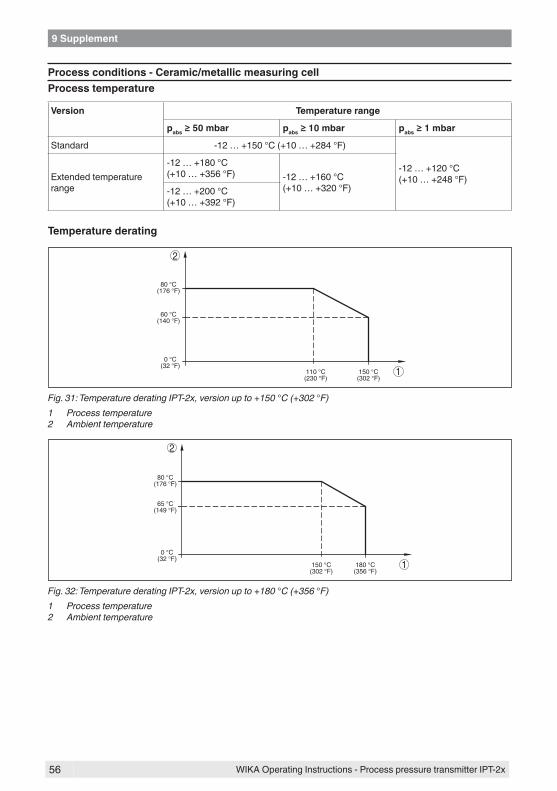
56
9 Supplement
WIKA Operating Instructions - Process pressure transmitter IPT-2x
Process conditions - Ceramic/metallic measuring cellProcess temperature
Version Temperature range
pabs≥50mbar pabs≥10mbar pabs≥1mbar
Standard -12 … +150 °C (+10 … +284 °F)
-12 … +120 °C (+10 … +248 °F)Extended temperature
range
-12 … +180 °C (+10 … +356 °F) -12 … +160 °C
(+10 … +320 °F)-12 … +200 °C (+10 … +392 °F)
Temperature derating
1
2
0 °C(32 °F)
60 °C(140 °F)
80 °C(176 °F)
150 °C(302 °F)
110 °C(230 °F)
Fig. 31: Temperature derating IPT-2x, version up to +150 °C (+302 °F)1 Process temperature2 Ambient temperature
1
2
0 °C(32 °F)
65 °C(149 °F)
80 °C(176 °F)
180 °C(356 °F)
150 °C(302 °F)
Fig. 32: Temperature derating IPT-2x, version up to +180 °C (+356 °F)1 Process temperature2 Ambient temperature
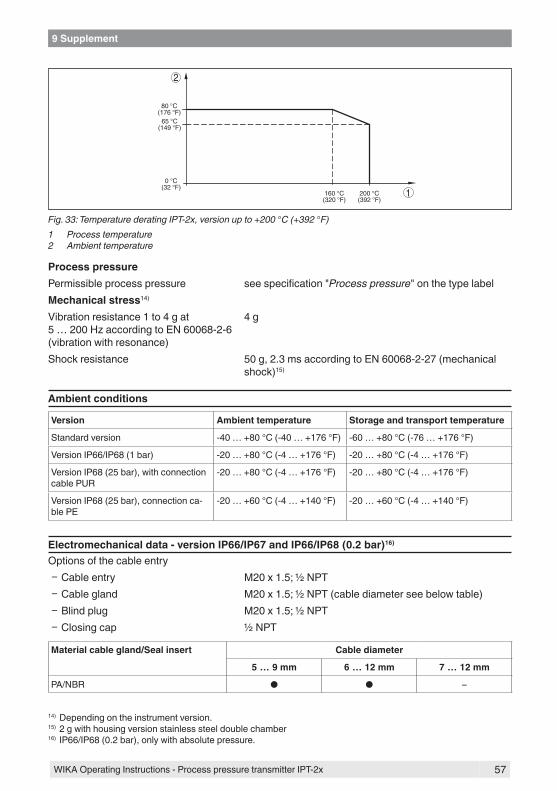
57
9 Supplement
WIKA Operating Instructions - Process pressure transmitter IPT-2x
1
2
0 °C(32 °F)
65 °C(149 °F)
80 °C(176 °F)
200 °C(392 °F)
160 °C(320 °F)
Fig. 33: Temperature derating IPT-2x, version up to +200 °C (+392 °F)1 Process temperature2 Ambient temperature
Process pressurePermissible process pressure see specification "Process pressure" on the type labelMechanical stress14)
Vibration resistance 1 to 4 g at 5 … 200 Hz according to EN 60068-2-6 (vibration with resonance)
4 g
Shock resistance 50 g, 2.3 ms according to EN 60068-2-27 (mechanical shock)15)
Ambient conditions
Version Ambient temperature Storage and transport temperature
Standard version -40 … +80 °C (-40 … +176 °F) -60 … +80 °C (-76 … +176 °F)
Version IP66/IP68 (1 bar) -20 … +80 °C (-4 … +176 °F) -20 … +80 °C (-4 … +176 °F)
Version IP68 (25 bar), with connection cable PUR
-20 … +80 °C (-4 … +176 °F) -20 … +80 °C (-4 … +176 °F)
Version IP68 (25 bar), connection ca-ble PE
-20 … +60 °C (-4 … +140 °F) -20 … +60 °C (-4 … +140 °F)
Electromechanical data - version IP66/IP67 and IP66/IP68 (0.2 bar)16)
Options of the cable entry Ʋ Cable entry M20 x 1.5; ½ NPT Ʋ Cable gland M20 x 1.5; ½ NPT (cable diameter see below table) Ʋ Blind plug M20 x 1.5; ½ NPT Ʋ Closing cap ½ NPT
Material cable gland/Seal insert Cable diameter
5 … 9 mm 6 … 12 mm 7 … 12 mm
PA/NBR ● ● –
14) Depending on the instrument version.15) 2 g with housing version stainless steel double chamber16) IP66/IP68 (0.2 bar), only with absolute pressure.
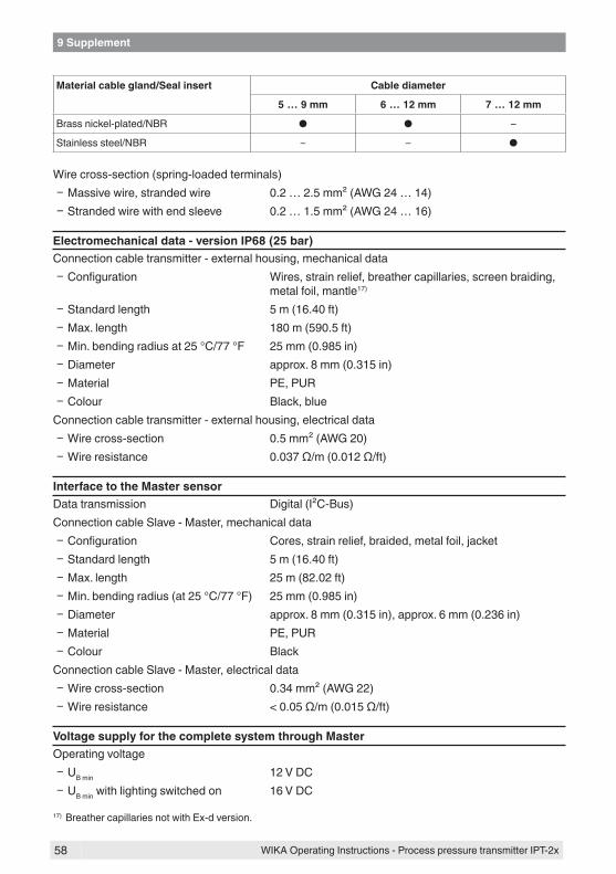
58
9 Supplement
WIKA Operating Instructions - Process pressure transmitter IPT-2x
Material cable gland/Seal insert Cable diameter
5 … 9 mm 6 … 12 mm 7 … 12 mm
Brass nickel-plated/NBR ● ● –
Stainless steel/NBR – – ●
Wire cross-section (spring-loaded terminals) Ʋ Massive wire, stranded wire 0.2 … 2.5 mm² (AWG 24 … 14) Ʋ Stranded wire with end sleeve 0.2 … 1.5 mm² (AWG 24 … 16)
Electromechanical data - version IP68 (25 bar)Connection cable transmitter - external housing, mechanical data
Ʋ Configuration Wires, strain relief, breather capillaries, screen braiding, metal foil, mantle17)
Ʋ Standard length 5 m (16.40 ft) Ʋ Max. length 180 m (590.5 ft) Ʋ Min. bending radius at 25 °C/77 °F 25 mm (0.985 in) Ʋ Diameter approx. 8 mm (0.315 in) Ʋ Material PE, PUR Ʋ Colour Black, blue
Connection cable transmitter - external housing, electrical data Ʋ Wire cross-section 0.5 mm² (AWG 20) Ʋ Wire resistance 0.037 Ω/m (0.012 Ω/ft)
Interface to the Master sensorData transmission Digital (I²C-Bus)Connection cable Slave - Master, mechanical data
Ʋ Configuration Cores, strain relief, braided, metal foil, jacket Ʋ Standard length 5 m (16.40 ft) Ʋ Max. length 25 m (82.02 ft) Ʋ Min. bending radius (at 25 °C/77 °F) 25 mm (0.985 in) Ʋ Diameter approx. 8 mm (0.315 in), approx. 6 mm (0.236 in) Ʋ Material PE, PUR Ʋ Colour Black
Connection cable Slave - Master, electrical data Ʋ Wire cross-section 0.34 mm² (AWG 22) Ʋ Wire resistance < 0.05 Ω/m (0.015 Ω/ft)
Voltage supply for the complete system through MasterOperating voltage
Ʋ UB min 12 V DC Ʋ UB min with lighting switched on 16 V DC
17) Breather capillaries not with Ex-d version.

59
9 Supplement
WIKA Operating Instructions - Process pressure transmitter IPT-2x
Ʋ UB max Depending on signal output and version of the master sensor
Potential connections and electrical separating measures in the instrumentElectronics Not non-floatingReference voltage18) 500 V ACConductive connection Between ground terminal and metallic process fitting
Electrical protective measures
Housing material Version Protection acc. to IEC 60529
Protection acc. to NEMA
Plastic
Single chamber
IP66/IP67 Type 4x
Aluminium IP66/IP67IP66/IP68 (0.2 bar)
Type 4xType 6P
Stainless steel (electro-polished) IP66/IP67IP69K
Type 4x-
Stainless steel (precision cast-ing)
IP66/IP67IP66/IP68 (0.2 bar)
Type 4xType 6P
Stainless steel Transmitter for external housing IP68 (25 bar) -
Altitude above sea level Ʋ by default up to 2000 m (6562 ft) Ʋ with connected overvoltage protection on the master sensor
up to 5000 m (16404 ft)
Pollution degree19) 4Protection rating (IEC 61010-1) II
9.2 Calculation of the total deviationThe total deviation of a pressure transmitter indicates the maximum measurement error to be ex-pected in practice. It is also called maximum practical deviation or operational error.According to DIN 16086, the total deviation Ftotal is the sum of the basic deviation Fperf and the long-term stability Fstab:Ftotal= Fperf + Fstab
The basic deviation Fperf consists of the thermal change of the zero signal and the output span FT as well as the deviation FKl:Fperf = √((FT)2 + (FKl)2)The thermal change of zero signal and output span FT is specified in chapter "Technical data". The basic temperature error FT is shown in a graphic. Depending on the measuring cell version and Turn down, this value must be multiplied with the additional factors FMZ and FTD:FT x FMZ x FTDAlso these values are specified in chapter "Technical data".
18) Galvanic separation between electronics and metal housing parts19) When used with fulfilled housing protection.

60
9 Supplement
WIKA Operating Instructions - Process pressure transmitter IPT-2x
This applies for a digital signal output through HART, Profibus PA or Foundation Fieldbus.With a 4 … 20 mA output, the thermal change of the current output Fa must be added:Fperf = √((FT)2 + (FKl)2 + (Fa)2)To provide a better overview, the formula symbols are listed together below:
• Ftotal: Total deviation• Fperf: Basic deviation• Fstab: Long-term stability• FT: Thermal change of zero signal and output span (temperature error)• FKl: Deviation• Fa: Thermal change of the current output• FMZ: Additional factor measuring cell version• FTD: Additional factor Turn down
9.3 Practical exampleDataLevel measurement in a small vessel, 500 mm height corresponds to 0.049 bar (4.9 KPa), superim-posed pressure 0.35 bar (35 KPa), medium temperature 40 °CIPT-2x Master and slave sensor each with nominal measuring range 0.4 bar (40 KPa), deviation < 0.1 %, process fitting G1 (piezoresistive measuring cell)The required values for the temperature error FT, deviation FKl and long-term stability Fstab are avail-able in the technical data.
1. Calculation of the Turn downTD = 0.4 bar/0.049 bar, TD = 8.2 : 1
2. Determination temperature error FT
The temperature error FT consists of the basic temperature error FTBasis , the additional factor meas-uring cell FMZ and the additional factor Turn Down FTD.
(TD
1:1
)
T / °C
50 °C 40 °C 20 °C 10 °C -40 °C 100 °C 150 °C
0,15
-0,15
-0,3
-0,45
-0,6
-0,75
-0,9
0,3
0,45
0,6
0,75
0,9
F/ %
TBas
is
Fig. 34: Determination of the basic temperature error for the above example: FTBasis = 0.15 %

61
9 Supplement
WIKA Operating Instructions - Process pressure transmitter IPT-2x
Accuracy classIn the compensated temperature range of 10 … +70 °C
0.075 %, 0.1 % 0.2 %
Factor FMZ 1 3
Tab. 19: Determination of the additional factor measuring cell for above example: FMZ = 1The additional factor FTD through Turn down is calculated according to the following formula:FTD = 0.5 x TD + 0.5, with TD = 8.2:1 of above calculationFTD = 0.5 x 8.2 + 0.5 = 4.6Determination of the temperature error master sensor for above example:FT = FTBasis x FMZ x FTD
FT = 0.15 % x 1 x 4.6FT = 0.69 %The temperature error of each sensor is hence 0.69 %
3. Determination of deviation and long-term stabilityThe required values for deviation FKl and long-term stability Fstab are available in the technical data:
Accuracy class Non-linearity, hysteresis and non-repeatability
TD≤5:1 TD > 5 : 1
0.075 % < 0.075 % < 0.015 % x TD
0.1 % < 0.1 % < 0.02 % x TD
0.2 % < 0.2 % < 0.04 % x TD
Tab. 20: Determination of the deviation from the table: FKl = 0.02 % x TD = 0.02 % x 8.2 = 0.16 %
Version
Measuring ranges > 1 bar < 0.1 % x TD/year
Measuring ranges > 1 bar, isolating liquid, synthetic oil, diaphragm Elgiloy (2.4711)
< 0.15 % x TD/year
Measuring range 1 bar < 0.15 % x TD/year
Measuring range 0.4 bar < 0.35 % x TD/year
Determination of the long-term stability from the table, consideration for one year: Fstab = 0.1 % x 8.2 = 0.82 %
4. Calculation of the total deviation- 1. step: Basic accuracy Fperf
Fperf = √((FT)2 + (FKl)2)FT = 0.69 %FKl= 0.16 % (calculation of above table)Fperf = √(0.69 %)2 + (0.16 %)2)Fperf = 0.71 %- 2. step: Total deviation Ftotal
Ftotal = Fperf + Fstab

62
9 Supplement
WIKA Operating Instructions - Process pressure transmitter IPT-2x
Fperf = 0.71 % (result of step 1)Fstab = 0.82 % (from top)Ftotal = 0.71 % + 0.82 % = 1.53 %The total deviation of each sensor is hence 1.53 %.
5. Calculation of the total deviation of the measuring systemBoth sensors are included in the calculation of the total deviation of the measurig system. With 4 … 20 mA master sensors the thermal error of the analogue output is also added:Ftotal = √(Ftotal-Master)2 + (Ftotal-Slave)2 + (Fa)2
0,3 %
-0,15 %-40°C -20°C 20°C 40°C 60°C 80°C
0,15 %
-0,3 %
Fig. 35: Fa through thermal change current output, in this example = 0.1 %
Ftotal = √(1.53 %)2 + (1.53 %)2 + (0.1 %)2)= 2.17 %The total deviation of the measuring system is hence 2.17 %.Deviation in mm: 2.17 % of 500 mm = 11 mmThe example shows that the measurement error in practice can be considerably higher than the basic accuracy. Reasons are temperature influence and Turn down.The thermal change of the current output is in this example is negligible.

63
9 Supplement
WIKA Operating Instructions - Process pressure transmitter IPT-2x
9.4 Dimensions
Housing
~ 69 mm(2.72")
ø 77 mm(3.03")
112
mm
(4.4
1")
M20x1,5/½ NPT
~ 116 mm(4.57")
116
mm
(4.5
7")
M20x1,5M20x1,5/½ NPT
~ 69 mm(2.72")
ø 77 mm(3.03")
117
mm
(4.6
1")
M20x1,5/½ NPT
~ 59 mm(2.32")
ø 80 mm(3.15")
112
mm
(4.4
1")
M20x1,5/½ NPT
ø 84 mm(3.31")
1 2
4
3
5
104
mm
(4.1
")
M20x1,5/½ NPT
~ 59 mm(2.3") ø 80 mm
(3.15")
Fig. 36: Housing versions in protection IP66/IP67 and IP66/IP68 (0.2 bar)1 Plastic single chamber (IP66/IP67)2 Aluminium - single chamber3 Stainless steel single chamber (electropolished)4 Stainless steel single chamber (precision casting)5 Stainless steel single chamber (electropolished) IP69K

64
9 Supplement
WIKA Operating Instructions - Process pressure transmitter IPT-2x
External housing with IP68 (25 bar) version
1
2
3
4
82 mm(3.23")
80 m
m(3
.15"
)10
8 m
m(4
.25"
)
41,6 mm(1.64")
~ 66 mm(2.60")
59 m
m(2
.32"
)
110 mm x 90 mm(4.33" x 3.54")
110 mm x 90 mm (4.33" x 3.54")
51 m
m(2
.01"
)
41,6 mm(1.64")
90 mm(3.54")
R 3,5 mm
(0.14")
3mm(0.12")
70 mm(2.76")
8 mm(0.32")
93 m
m(3
.66"
)
110
mm
(4.3
3")
Fig. 37: IP68 version with external housing1 Lateral cable outlet2 Cable outlet axial3 Plastic housing4 Stainless steel housing, electropolished

65
9 Supplement
WIKA Operating Instructions - Process pressure transmitter IPT-2x
IPT-2x,threadedfittingnotfront-flush
1 2
3
4 5
23 m
m(0
.91"
)
G½
58 m
m(2
.28"
)
3 m
m(0
.12"
)
ø 3 mm (0.12")
ø 6 mm (0.24")
ø 36 mm (1.42")
ø 36 mm (1.42")
ø 36 mm (1.42")
ø 36 mm (1.42")
ø 44,5 mm (1.75")
½ NPT
54 m
m(2
.13"
)
19 m
m(0
.75"
)
M20x1,5
23 m
m(0
.91"
)58
mm
(2.2
8")
5 m
m(0
.20"
)
ø 3 mm (0.12") ø 6 mm
(0.24") G½
G¼
120
mm
(4.7
0")
20 m
m(0
.79"
)
4 m
m(0
.16"
)
ø 17,5 mm (0.69")
SW 27mm(1.06")
SW 27mm(1.06")
SW 27mm(1.06")
SW 27mm(1.06")
SW 27mm(1.06")
¼ NPT
½ NPT
54 m
m(2
.13"
)
14 m
m(0
.55"
)
19 m
m(0
.75"
)
Fig. 38: IPT-2x, threaded fitting not front-flush1 G½ manometer connection (EN 837)2 M20 x 1.5 manometer connection (EN 837)3 G½ A inside G¼ (ISO 228-1)4 ½ NPT, inside ¼ NPT (ASME B1.20.1)5 ½ NPT PN 1000
For the version with "Second Line of Defense", the measure of length increases by 17 mm (0.67 in).

66
9 Supplement
WIKA Operating Instructions - Process pressure transmitter IPT-2x
IPT-2x,threadedfittingfront-flush
1 2 3
654
21 m
m(0
.83"
)
79 m
m(3
.11"
)
79 m
m(3
.11"
)
22 m
m(0
.87"
)
ø 55 mm(2.17")
78 m
m(3
.07"
)
78 m
m(3
.07"
)21
mm
(0.8
3")
22 m
m(0
.87"
)
ø 55 mm(2.17")
G1½
1½ NPT
G½ G1
58 m
m(2
.28"
)
M44x1,25
59 m
m(2
.32"
)
20,5
mm
(0.8
1")
20,5
mm
(0.8
1")
ø 18mm (0.71")
ø 30 mm (1.18")
ø 36 mm (1.42")
ø 36 mm (1.42")
ø 36 mm (1.42")
ø 40 mm (1.57")
ø 36 mm (1.42") ø 40 mm
(1.57")
ø 40 mm (1.59")
ø 40 mm (1.59")
SW 41mm(1.61")
SW 27mm(1.06")
SW 46mm(1.81")
M44x1,25
SW 46mm(1.81")
SW 46mm(1.81")
SW 46mm(1.81")
Fig. 39: IPT-2x, threaded fitting front-flush1 G½ (ISO 228-1) with O-ring2 G1 (ISO 228-1) with O-ring3 G1½ (DIN3852-A)4 M44 x 1.255 3 and 4 with temperature adapter and screen sheet for 180 °C/200 °C6 1½ NPT (ASME B1.20.1)
For the version with "Second Line of Defense", the measure of length increases by 17 mm (0.67 in).

67
9 Supplement
WIKA Operating Instructions - Process pressure transmitter IPT-2x
IPT-2x,hygienicfitting150°C(piezoresistive/straingaugemeasuringcell)
79 m
m(3
.11"
)
ø 78 mm(3.05")
82 m
m(3
.23"
)
ø 92 mm(3.60")
ø 64 mm (2.52")
ø 36 mm (1.42")
ø 36 mm (1.42")
ø 36 mm (1.42")
ø 36 mm (1.42")
ø 36 mm (1.42")
ø 36 mm (1.42")
79 m
m(3
.11"
)
ø 84 mm (3.31")
79 m
m(3
.11"
)
79 m
m(3
.11"
)
ø 65 mm(2.56")
ø 105 mm(4.13")
79 m
m(3
.11"
)
ø 78 mm (3.07")
1 2 3
654
Fig. 40: IPT-2x, hygienic fitting 150 °C (piezoresistive/strain gauge measuring cell)1 Clamp 2" PN16 (ø64mm) DIN 32676, ISO 28522 Hygienic fitting with compression nut F 40 PN 253 Varivent N 50-40 PN 254 Collar socket DN 40 PN 40, DIN 118515 Collar socket DN 50 PN 25 Form A, DIN 118646 DRD PN 40
For the version with "Second Line of Defense", the measure of length increases by 17 mm (0.67 in).

68
9 Supplement
WIKA Operating Instructions - Process pressure transmitter IPT-2x
IPT-2x,hygienicfitting150°C(metallic/ceramicmeasuringcell)78
mm
(3.0
7")
78 m
m(3
.07"
)
ø 64 mm(2.52")
ø 78 mm(3.07")
ø 78 mm(3.07")
78 m
m(3
.07"
)
ø 84 mm(3.31")
78 m
m(3
.07"
)
78 m
m(3
.07"
)
ø 66 mm(2.60")ø 78 mm
(3.07")
83 m
m(3
.27"
)
1 2 3
654
Fig. 41: IPT-2x, hygienic fitting 150 °C (metallic/ceramic measuring cell)1 Clamp 2" PN16 (ø64mm) DIN 32676, ISO 28522 Hygienic fitting with compression nut F 40 PN 253 Varivent N 50-40 PN 254 Collar socket DN 40 PN 40, DIN 118515 Collar socket DN 50 PN 25 Form A, DIN 118646 DRD PN 40
For the version with "Second Line of Defense", the measure of length increases by 17 mm (0.67 in).

69
9 Supplement
WIKA Operating Instructions - Process pressure transmitter IPT-2x
IPT-2x,flangeconnection150°C(piezoresistive/straingaugemeasuringcell)
5.91"6.50"7.87"
40 4050 4080 40
9.25"100 40150 16
6.50"50 40
DNmm
inch
PN D kb d2 d4 f RL d5
40 40 150 18 11050 40 165 20 125
4xø184xø18
88102
33
100 40 235 24 190 8xø22 162 380 40 200 24 160 8xø18 138 3
-
--
-
3
1
1
2
3
4
4
150 16 285 22 240 8xø22 212 3
-
-
--
--
--
-
-
-
--
-
-
-
--
-
-50 40 165 20 125 4xø18 102 3
2“ 150 lbs3“ 150 lbs
3.62"4xø 0.75"4.75"0.75"7.50" 4xø 0.75"6“ 5“6.00"
0.71"
11.22"
0.79"0.95"0.95"0.87"0.79"
4.33"4.92"6.30"7.48"9.45"4.92"
4xø 0.71"4xø 0.71"
4xø 0.71"
8xø 0.71"8xø 0.87"8xø 0.87"
3.47"4.02"5.43"6.38"8.35"4.02"
0.12"0.12"0.12"0.12"0.12"0.12"
0.06"0.06"0.94"
80 m
m(3
.15"
)
d4
k
D
f b
d2
RL
d5
Fig. 42: IPT-2x, flange connection 150 °C (piezoresistive/strain gauge measuring cell)1 Flange connection according to DIN 25012 Flange connection according to ASME B16.53 Order-specific4 Order-specific
For the version with "Second Line of Defense", the measure of length increases by 17 mm (0.67 in).

70
9 Supplement
WIKA Operating Instructions - Process pressure transmitter IPT-2x
IPT-2x,flangeconnection180°C/200°C(ceramic/metallicmeasuringcell)
5.91"6.50"7.87"
40 4050 4080 40
9.25"100 40150 40
6.50"50 40
DNmm
inch
PN D kb d2 d4 f RL d5
40 40 150 18 11050 40 165 20 125
4xø184xø18
88102
33
100 40 235 24 190 8xø22 162 380 40 200 24 160 8xø18 138 3
-
--
-
5 6
5 6
150 40 300 28 250 8xø26 218 3
-
-
--
--
--
-
-
-
--
-
-
-
--
-
-50 40 165 20 125 4xø18 102 3
2“ 150 lbs3“ 150 lbs
3.62"4xø 0.75"4.75"0.77"7.48" 4xø 0.75"6“ 5“5.91"
0.71"
11.81"
0.79"0.95"0.95"1.10"0.79"
4.33"4.92"6.30"7.48"9.84"4.92"
4xø 0.71"4xø 0.71"
4xø 0.71"
8xø 0.71"8xø 0.87"8xø 1.02"
3.47"4.02"5.43"6.38"8.58"4.02"
0.12"0.12"0.12"0.12"0.12"0.12"
0.12"0.12"0.96"
1
1
2
121
mm
(4.7
6")
82 m
m(3
.23"
)
d4
k
D
fb
d2
RL
d5
4
3
Fig. 43: IPT-2x, flange connection 180 °C/200 °C (ceramic/metallic measuring cell)1 Flange connection according to DIN 25012 Flange connection according to ASME B16.53 Temperature adapter up to 180 °C4 Temperature screen sheet up to 200 °C5 Order-specific6 Order-specific
For the version with "Second Line of Defense", the measure of length increases by 17 mm (0.67 in).

71
9 Supplement
WIKA Operating Instructions - Process pressure transmitter IPT-2x
9.5 TrademarkAll the brands as well as trade and company names used are property of their lawful proprietor/originator.

72
INDEX
WIKA Operating Instructions - Process pressure transmitter IPT-2x
INDEX
AAdjustment 32, 33, 34, 35, 36
– Level 37 – Unit 30
AI FB1 Function Block 38
CChannel 38Characteristic values of the differential pressure transmitter 41Connection
– Steps 25 – Technology 24
Current output 41
EElectrical connection 24
FFault
– Rectification 42Fault rectification 42Functional principle 9
GGas-tight leadthrough (Second Line of Defense) 16
LLinearisation 38
MMaintenance 42Measurement setup
– Density measurement 20 – Differential pressure measurement 19 – Interface measurement 19 – Level measurement 18, 21
PParameterization example 31Peak value indicator 39Position correction 30Pressure compensation 16
– Ex d 15 – Second Line of Defense 16 – Standard 15
SSeal concept 11
Set display parameters 39Simulation 40

73
Notes
WIKA Operating Instructions - Process pressure transmitter IPT-2x

74
Notes
WIKA Operating Instructions - Process pressure transmitter IPT-2x

75
Notes
WIKA Operating Instructions - Process pressure transmitter IPT-2x

76
Printing date:
WIKA Alexander Wiegand SE & Co. KGAlexander-Wiegand-Straße 3063911 KlingenbergGermanyPhone (+49) 9372/132-0Fax (+49) 9372 132-406E-mail: [email protected]
55740-EN-200529
All statements concerning scope of delivery, application, practi-cal use and operating conditions of the sensors and processing systems correspond to the information available at the time of printing.
Process pressure transmitter IPT-2x