Embed Size (px)
Citation preview

O P E R A T I N G I N S T R U C T I O N S
MPS-CPosition sensors
Mounting, operating, maintenance
Described product
MPS-C sensor for C-slot cylinders
Manufacturer
SICK AGErwin-Sick-Str. 179183 WaldkirchGermany
Legal information
This work is protected by copyright. Any rights derived from the copyright shall bereserved for SICK AG. Reproduction of this document or parts of this document is onlypermissible within the limits of the legal determination of Copyright Law. Any modifica‐tion, abridgment or translation of this document is prohibited without the express writ‐ten permission of SICK AG.
The trademarks stated in this document are the property of their respective owner.
© SICK AG. All rights reserved.
Original document
This document is an original document of SICK AG.
2 O P E R A T I N G I N S T R U C T I O N S | MPS-C 8019721/YYM3/2016-06-24 | SICKSubject to change without notice

Contents
1 About this document........................................................................ 51.1 Information on the operating instructions.............................................. 51.2 Scope......................................................................................................... 51.3 Explanation of symbols............................................................................ 51.4 Further information................................................................................... 61.5 Customer service...................................................................................... 6
2 Safety information............................................................................ 72.1 Intended use............................................................................................. 72.2 Improper use............................................................................................. 72.3 Limitation of liability................................................................................. 72.4 Requirements for skilled persons and operating personnel................. 82.5 Hazard warnings and operational safety................................................ 82.6 Repairs...................................................................................................... 8
3 Product description........................................................................... 93.1 Product ID.................................................................................................. 93.2 Product characteristics............................................................................. 9
4 Transport and storage....................................................................... 114.1 Transport................................................................................................... 114.2 Transport inspection................................................................................. 114.3 Storage...................................................................................................... 11
5 Mounting............................................................................................. 125.1 Preparation for mounting......................................................................... 125.2 Mounting the sensor................................................................................ 12
6 Electrical installation........................................................................ 146.1 Safety......................................................................................................... 146.2 Pin allocation of the connections............................................................ 166.3 Connecting the supply voltage................................................................. 166.4 Wiring the digital switching output.......................................................... 17
7 Commissioning.................................................................................. 187.1 Overview of commissioning steps........................................................... 187.2 Commissioning the sensor for the first time........................................... 18
8 Operation............................................................................................ 198.1 IO-Link........................................................................................................ 198.2 Operating and status indicators.............................................................. 198.3 General notes on operation..................................................................... 208.4 Teach-in mode........................................................................................... 23
9 Maintenance...................................................................................... 34
CONTENTS
8019721/YYM3/2016-06-24 | SICK O P E R A T I N G I N S T R U C T I O N S | MPS-C 3Subject to change without notice

9.1 Maintenance............................................................................................. 349.2 Repairs...................................................................................................... 34
10 Decommissioning............................................................................. 35
11 Technical data.................................................................................... 3611.1 Performance............................................................................................. 3611.2 Interfaces.................................................................................................. 3611.3 Mechanics/electronics............................................................................. 3611.4 Ambient data............................................................................................. 37
12 Annex.................................................................................................. 3812.1 EU declaration of conformity.................................................................... 38
CONTENTS
4 O P E R A T I N G I N S T R U C T I O N S | MPS-C 8019721/YYM3/2016-06-24 | SICKSubject to change without notice
1 About this document
1.1 Information on the operating instructions
These operating instructions provide important information on how to use sensors fromSICK AG.
Prerequisites for safe work are:
• Compliance with all safety notes and handling instructions supplied.• Compliance with local work safety regulations and general safety regulations for
sensor applications.
The operating instructions are intended to be used by qualified personnel and electricalspecialists.
NOTERead these operating instructions carefully before starting any work on the sensor, inorder to familiarize yourself with the sensor and its functions.
The instructions constitute an integral part of the product and are to be stored in theimmediate vicinity of the sensor so they remain accessible to staff at all times. If thesensor is passed on to a third party, these operating instructions should be handedover with it.
These operating instructions do not provide information on operating the machine inwhich the sensor is integrated. For information about this, refer to the operating instruc‐tions of the particular machine.
1.2 Scope
These operating instructions are used for incorporating a sensor into a customer sys‐tem. Step-by-step instructions are given for all the actions required.
These instructions apply to all available device variants of the sensor.
Available device variants are listed on the online product page.
b www.sick.com/mps-c
Commissioning is described using one particular device variant as an example.
Simplified device designation in the document
In the following, the sensor is referred to in simplified form as “MPS-C”.
1.3 Explanation of symbols
Warnings and important information in this document are labeled with symbols. Thewarnings are introduced by signal words that indicate the extent of the danger. Thesewarnings must be observed at all times and care must be taken to avoid accidents, per‐sonal injury, and material damage.
DANGER… indicates a situation of imminent danger, which will lead to a fatality or serious inju‐ries if not prevented.
ABOUT THIS DOCUMENT 1
8019721/YYM3/2016-06-24 | SICK O P E R A T I N G I N S T R U C T I O N S | MPS-C 5Subject to change without notice
WARNING… indicates a potentially dangerous situation, which may lead to a fatality or seriousinjuries if not prevented.
CAUTION… indicates a potentially dangerous situation, which may lead to minor/slight injuries ifnot prevented.
NOTICE… indicates a potentially harmful situation, which may lead to material damage if notprevented.
NOTE… highlights useful tips and recommendations as well as information for efficient andtrouble-free operation.
1.4 Further information
NOTEAll the documentation available for the sensor can be found on the online product pageat:
b www.sick.com/mps-c
The following information is available for download there:
• Type-specific online data sheets for device variants, containing technical data anddimensional drawings
• EU declaration of conformity for the product family• Dimensional drawings and 3D CAD dimension models in various electronic for‐
mats• These operating instructions, available in English and German, and in other lan‐
guages if necessary• Other publications related to the sensors described here• Publications dealing with accessories• IO-Link driver files and parameter descriptions
1.5 Customer service
If you require any technical information, our customer service department will be happyto help. To find your representative, see the final page of this document.
NOTEBefore calling, make a note of all type label data such as type code, serial number, etc.to ensure faster processing.
1 ABOUT THIS DOCUMENT
6 O P E R A T I N G I N S T R U C T I O N S | MPS-C 8019721/YYM3/2016-06-24 | SICKSubject to change without notice

2 Safety information
2.1 Intended use
The sensor from the MPS-C product family is an intelligent, magnetic position sensor. Itis used for non-contact detection of the piston stroke of pneumatic drives with axiallymagnetized permanent magnets.
SICK AG assumes no liability for losses or damage arising from the use of the product,either directly or indirectly. This applies in particular to use of the product that does notconform to its intended purpose and is not described in this documentation.
NOTICERadio interference may occur when the sensor is used in residential areas!
b Only use the device in industrial environments (EN 61000-6-4).
2.2 Improper use
• The sensor does not constitute a safety-relevant device according to the EC Machi‐nery Directive (2006/42/EC).
• The sensor must not be used in explosion-hazardous areas.• Any other use that is not described as intended use is prohibited.• Any use of accessories not specifically approved by SICK AG is at your own risk.
NOTICEDanger due to improper use!Any improper use can result in dangerous situations.Therefore, take note of the following information:
b The sensor should be used only in line with intended use specifications.b All information in these operating instructions must be strictly complied with.
2.3 Limitation of liability
Applicable standards and regulations, the latest state of technological development,and our many years of knowledge and experience have all been taken into accountwhen assembling the data and information contained in these operating instructions.The manufacturer accepts no liability for damage caused by:
■ Failing to observe the operating instructions■ Improper use■ Use by untrained personnel■ Unauthorized conversions■ Technical modifications■ Use of unauthorized spare parts, consumables, and accessories
With special variants, where optional extras have been ordered, or owing to the latesttechnical changes, the actual scope of delivery may vary from the features and illustra‐tions shown here.
SAFETY INFORMATION 2
8019721/YYM3/2016-06-24 | SICK O P E R A T I N G I N S T R U C T I O N S | MPS-C 7Subject to change without notice
2.4 Requirements for skilled persons and operating personnel
WARNINGRisk of injury due to insufficient training.Improper handling of the sensor may result in considerable personal injury and mate‐rial damage.
■ All work must only ever be carried out by the stipulated persons.
The operating instructions state the following qualification requirements for the variousareas of work:
■ Instructed personnel have been briefed by the operating entity about the tasksassigned to them and about potential dangers arising from improper action.
■ Skilled personnel have the specialist training, skills, and experience, as well asknowledge of the relevant regulations, to be able to perform tasks assigned tothem and to detect and avoid any potential dangers independently.
■ Electricians have the specialist training, skills, and experience, as well as knowl‐edge of the relevant standards and provisions to be able to carry out work on elec‐trical systems and to detect and avoid any potential dangers independently. In Ger‐many, electricians must meet the specifications of the BGV A3 Work Safety Regu‐lations (e.g., Master Electrician). Other relevant regulations applicable in othercountries must be observed.
The following qualifications are required for various activities:
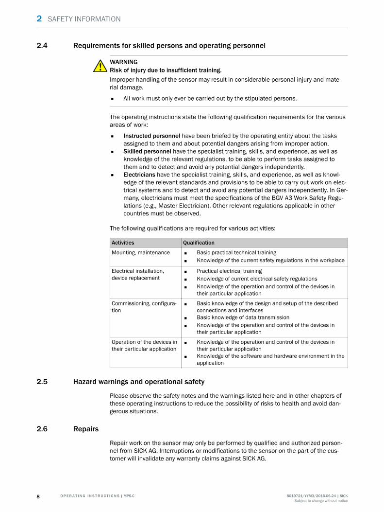
Activities Qualification
Mounting, maintenance ■ Basic practical technical training■ Knowledge of the current safety regulations in the workplace
Electrical installation,device replacement
■ Practical electrical training■ Knowledge of current electrical safety regulations■ Knowledge of the operation and control of the devices in
their particular application
Commissioning, configura‐tion
■ Basic knowledge of the design and setup of the describedconnections and interfaces
■ Basic knowledge of data transmission■ Knowledge of the operation and control of the devices in
their particular application
Operation of the devices intheir particular application
■ Knowledge of the operation and control of the devices intheir particular application
■ Knowledge of the software and hardware environment in theapplication
2.5 Hazard warnings and operational safety
Please observe the safety notes and the warnings listed here and in other chapters ofthese operating instructions to reduce the possibility of risks to health and avoid dan‐gerous situations.
2.6 Repairs
Repair work on the sensor may only be performed by qualified and authorized person‐nel from SICK AG. Interruptions or modifications to the sensor on the part of the cus‐tomer will invalidate any warranty claims against SICK AG.
2 SAFETY INFORMATION
8 O P E R A T I N G I N S T R U C T I O N S | MPS-C 8019721/YYM3/2016-06-24 | SICKSubject to change without notice

3 Product description
3.1 Product ID
3.1.1 Type label
The type label gives information for identification of the sensor.
MPS-xxxxxxxx15511079360
D-79183 Waldkirch
Made in Hungary
1 32
1 Type code2 Serial number3 Production date (yyww)
3.1.2 Device view
1 23 45 6
1 Setscrew 22 LED window 23 LED window 14 Keypad5 Setscrew 16 Connection
3.2 Product characteristics
3.2.1 Product features
The MPS-C position sensor is used for non-contact linear position measurement mainlyon pneumatic cylinders, grippers, and slides with C-slots.
3.2.2 Operating principle
Principle of operation
The MPS-C determines the position of an encoder magnet via a row of Hall sensors.
Resolution
The sensor resolution describes the minimum, specifiable magnet route change as out‐put by the sensor.
PRODUCT DESCRIPTION 3
8019721/YYM3/2016-06-24 | SICK O P E R A T I N G I N S T R U C T I O N S | MPS-C 9Subject to change without notice

Sampling rate
The sampling rate indicates the time interval in which the signal is updated at the out‐puts.
Speed
When specifying the speed, a distinction is made between “full stroke operation” and“partial stroke operation”.
In full stroke operation, the piston stroke is less than the measuring range and themagnet does not leave the measuring range.
In partial stroke operation, the piston stroke is greater than the measuring range andthe magnet leaves the measuring range.
The piston speed is max. 3 m/s and max. 1.5 m/s for full stroke and partial strokeoperation respectively.
Repeatability/Reproducibility
Repeatability/reproducibility is defined as any move to a preset position from the samedirection in every case.
Blind zone
blind zones
Figure 1: Sensor blind zones
The total length of the sensor is slightly longer than its measuring range. The differenceis called the blind zone. The blind zone is 7.5 mm on each side.
Linearity error
The linearity error describes the maximum deviation of the output signal from an idealstraight line. It is measured in millimeters.
3 PRODUCT DESCRIPTION
10 O P E R A T I N G I N S T R U C T I O N S | MPS-C 8019721/YYM3/2016-06-24 | SICKSubject to change without notice
4 Transport and storage
4.1 Transport
For your own safety, please read and observe the following notes:
NOTEDamage to the sensor due to improper transport.
■ The device must be packaged for transport with protection against shock anddamp.
■ Recommendation: Use the original packaging as it provides the best protection.■ Transport should be performed by specialist staff only.■ The utmost care and attention is required at all times during unloading and trans‐
portation on company premises.■ Note the symbols on the packaging.■ Do not remove packaging until immediately before you start mounting.
4.2 Transport inspection
Immediately upon receipt at the receiving work station, check the delivery for complete‐ness and for any damage that may have occurred in transit. In the case of transit dam‐age that is visible externally, proceed as follows:
■ Do not accept the delivery or only do so conditionally.■ Note the scope of damage on the transport documents or on the transport compa‐
ny’s delivery note.■ File a complaint.
NOTEComplaints regarding defects should be filed as soon as these are detected. Damageclaims are only valid before the applicable complaint deadlines.
4.3 Storage
Store the device under the following conditions:
■ Recommendation: Use the original packaging.■ Do not store outdoors.■ Store in a dry area that is protected from dust.■ So that any residual damp can evaporate, do not package in airtight containers.■ Do not expose to any aggressive substances.■ Protect from sunlight.■ Avoid mechanical shocks.■ Storage temperature: see "Technical data", page 36.■ Relative humidity: see "Technical data", page 36.■ For storage periods of longer than 3 months, check the general condition of all
components and packaging on a regular basis.
TRANSPORT AND STORAGE 4
8019721/YYM3/2016-06-24 | SICK O P E R A T I N G I N S T R U C T I O N S | MPS-C 11Subject to change without notice
5 Mounting
5.1 Preparation for mounting
5.1.1 Mounting requirements
NOTICERadio interference may occur when the sensor is used in residential areas!Only use the device in industrial environments (EN 61000-6-4).
■ Typical space requirements for sensor, see "Mechanics/electronics", page 36.■ Comply with technical data, such as the permitted ambient conditions for opera‐
tion of the sensor (e.g., temperature range, EM interference emissions), see "Tech‐nical data", page 36.
■ To prevent condensation, avoid exposing the sensor to rapid changes in tempera‐ture.
■ Protect the sensor from direct sunlight.■ Only mount the sensor using the screw connections provided for this purpose.
Mounting location
When selecting the mounting location, the following factors must be considered:
■ The mounting location must be as free from (electro)magnetic disturbance fieldsas possible.
■ Mounting the sensor requires a C-slot that runs parallel to the magnet’s axis ofmotion.
■ The distance (length of cable) to the IO-Link master must not exceed 20 m.
Equipment required
■ Tool and tape measure.
5.1.2 Scope of delivery
The sensor’s scope of delivery includes:
■ 1 MPS-C sensor in the version ordered■ 1 set of quick-start instructions■ 1 “IO-Link” leaflet■ 1 Allen wrench (size 1.5 mm)
Accessories:
Accessories (such as cables and fixing adapters) are only provided if they are orderedseparately.
5.2 Mounting the sensor
NOTICERisk of damage to the sensorIf the setscrews on the sensor housing are tightened excessively, the sensor may bedamaged.
b Observe the maximum tightening torque of 0.4 Nm.
5 MOUNTING
12 O P E R A T I N G I N S T R U C T I O N S | MPS-C 8019721/YYM3/2016-06-24 | SICKSubject to change without notice

Mounting the sensor
1 2
Figure 2: Mounting the sensor in the C-slot
1. Insert the sensor into the C-slot 1.2. Push the sensor into the required position.
Take into account the measuring object length and the blind zones of the sensor.3. Push the sensor into the C-slot and tighten the setscrews slightly.4. Use the tape measure to check the position of the sensor and correct it if neces‐
sary.5. Push the sensor into the C-slot and tighten both setscrews between 0.2 Nm and
0.4 Nm2.
MOUNTING 5
8019721/YYM3/2016-06-24 | SICK O P E R A T I N G I N S T R U C T I O N S | MPS-C 13Subject to change without notice
6 Electrical installation
6.1 Safety
6.1.1 Notes on the electrical installation
CAUTIONDanger due to incorrect supply voltage!An incorrect supply voltage may result in injuries from electric shocks and/or damage tothe device.
■ Only operate the sensor with safety extra-low voltage (SELV).
NOTICESensor damage or unpredictable operation due to working with live parts.Working with live parts may result in unpredictable operation.
■ Only carry out wiring work when the power is off.■ Only connect and disconnect electrical connections when the power is off.
■ The electrical installation must only be performed by electrically qualified person‐nel.
■ Standard safety requirements must be met when working in electrical systems.■ Only switch on the supply voltage for the device when the connection tasks have
been completed and the wiring has been thoroughly checked.■ When using extension cables with open ends, ensure that bare wire ends do not
come into contact with each other (risk of short-circuit when supply voltage isswitched on!). Wires must be appropriately insulated from each other.
■ Wire cross-sections in the supply cable from the customer’s power system must bedesigned in accordance with the applicable standards. When this is being done inGermany, observe the following standards: DIN VDE 0100 (Part 430) and DIN VDE0298 (Part 4) and/or DIN VDE 0891 (Part 1).
■ Circuits connected to the device must be designed as SELV circuits (SELV = SafetyExtra Low Voltage).
■ Protect the device with a separate fuse at the start of the supply circuit.
A shielded cable is not required in order to adhere to the electromagnetic compatibilityguidelines specified by DIN EN 60947-5-2. It is recommended, however, especiallywhen working with longer connecting cables.
The IP protection class for the sensor is only achieved if the connected cable is com‐pletely screwed in.
6.1.2 Wiring notes
NOTEPreassembled cables can be found online at:
b www.sick.com/mps-c
Please observe the following wiring notes:
■ During installation, pay attention to the different cable groups. The cables aregrouped into the following four groups according to their sensitivity to interferenceor radiated emissions:
6 ELECTRICAL INSTALLATION
14 O P E R A T I N G I N S T R U C T I O N S | MPS-C 8019721/YYM3/2016-06-24 | SICKSubject to change without notice
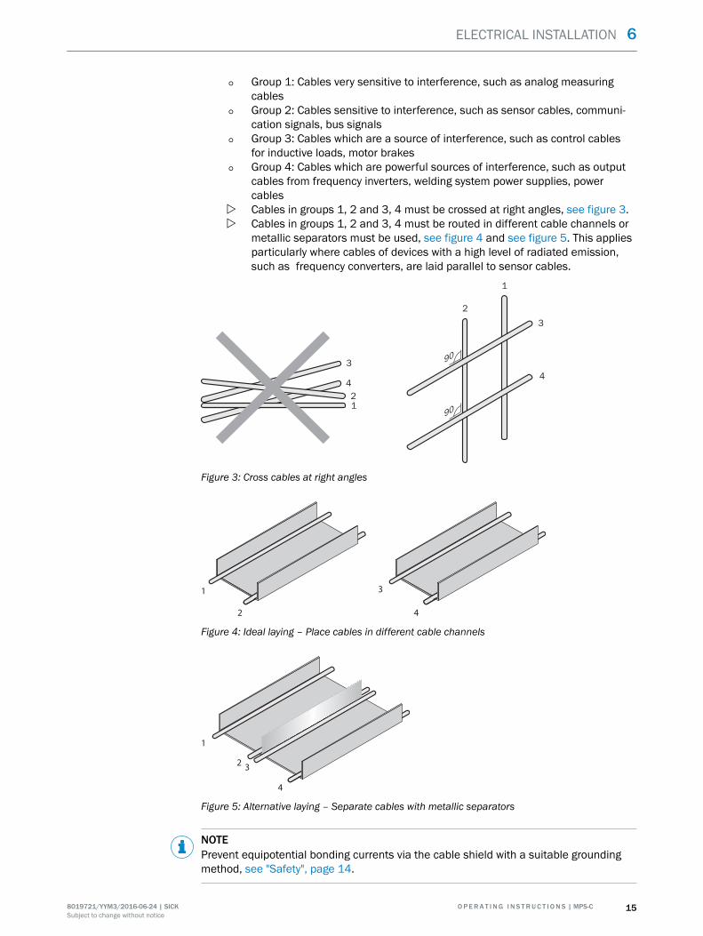
° Group 1: Cables very sensitive to interference, such as analog measuringcables
° Group 2: Cables sensitive to interference, such as sensor cables, communi‐cation signals, bus signals
° Group 3: Cables which are a source of interference, such as control cablesfor inductive loads, motor brakes
° Group 4: Cables which are powerful sources of interference, such as outputcables from frequency inverters, welding system power supplies, powercables
w Cables in groups 1, 2 and 3, 4 must be crossed at right angles, see figure 3.w Cables in groups 1, 2 and 3, 4 must be routed in different cable channels or
metallic separators must be used, see figure 4 and see figure 5. This appliesparticularly where cables of devices with a high level of radiated emission,such as frequency converters, are laid parallel to sensor cables.
1
2
4
3
1
2
4
3
90
90
Figure 3: Cross cables at right angles
1
2
3
4
Figure 4: Ideal laying – Place cables in different cable channels
1
23
4
Figure 5: Alternative laying – Separate cables with metallic separators
NOTEPrevent equipotential bonding currents via the cable shield with a suitable groundingmethod, see "Safety", page 14.
ELECTRICAL INSTALLATION 6
8019721/YYM3/2016-06-24 | SICK O P E R A T I N G I N S T R U C T I O N S | MPS-C 15Subject to change without notice
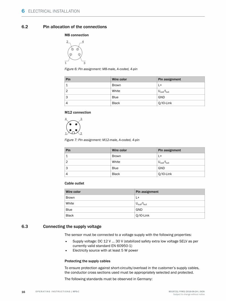
6.2 Pin allocation of the connections
M8 connection
42
31
Figure 6: Pin assignment: M8-male, A-coded, 4-pin
Pin Wire color Pin assignment
1 Brown L+
2 White Uout/Iout
3 Blue GND
4 Black Q/IO-Link
M12 connection
1
4 3
2
Figure 7: Pin assignment: M12-male, A-coded, 4-pin
Pin Wire color Pin assignment
1 Brown L+
2 White Uout/Iout
3 Blue GND
4 Black Q/IO-Link
Cable outlet
Wire color Pin assignment
Brown L+
White Uout/Iout
Blue GND
Black Q/IO-Link
6.3 Connecting the supply voltage
The sensor must be connected to a voltage supply with the following properties:
• Supply voltage: DC 12 V ... 30 V (stabilized safety extra low voltage SELV as percurrently valid standard EN 60950-1)
• Electricity source with at least 5 W power
Protecting the supply cables
To ensure protection against short-circuits/overload in the customer’s supply cables,the conductor cross sections used must be appropriately selected and protected.
The following standards must be observed in Germany:
6 ELECTRICAL INSTALLATION
16 O P E R A T I N G I N S T R U C T I O N S | MPS-C 8019721/YYM3/2016-06-24 | SICKSubject to change without notice
• DIN VDE 0100 (part 430)• DIN VDE 0298 (part 4) and/or DIN VDE 0891 (part 1)
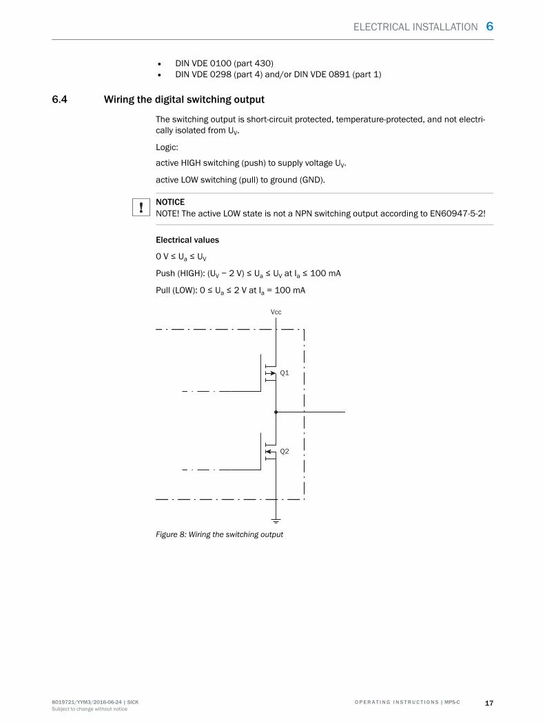
6.4 Wiring the digital switching output
The switching output is short-circuit protected, temperature-protected, and not electri‐cally isolated from UV.
Logic:
active HIGH switching (push) to supply voltage UV.
active LOW switching (pull) to ground (GND).
NOTICENOTE! The active LOW state is not a NPN switching output according to EN60947-5-2!
Electrical values
0 V ≤ Ua ≤ UV
Push (HIGH): (UV − 2 V) ≤ Ua ≤ UV at Ia ≤ 100 mA
Pull (LOW): 0 ≤ Ua ≤ 2 V at Ia = 100 mA
Q1
Q2
Vcc
Figure 8: Wiring the switching output
ELECTRICAL INSTALLATION 6
8019721/YYM3/2016-06-24 | SICK O P E R A T I N G I N S T R U C T I O N S | MPS-C 17Subject to change without notice
7 Commissioning
7.1 Overview of commissioning steps
■ Connect the voltage supply.■ Commission the sensor using the factory settings.■ Configure the sensor.
7.2 Commissioning the sensor for the first time
1. Connect the voltage supply.2. Wait until the yellow LED stops flashing (sensor is ready for operation).
The magnet may need to be moved inside the measuring range in order to betaught into the sensor.
NOTEWhen the sensor is ready for operation and a sufficiently strong magnet field isregistered in the measuring range, the LED lights up permanently. The yellow LEDgoes out if no magnet is registered in the measuring range.The yellow LED flashes at 4 Hz if an error is detected.
The sensor is supplied with the following settings, made at the factory:
■ Current output active (analog), IO-Link operation possible■ Measuring range fully active
To configure the sensor, either the capacitive keypad (see "Operation", page 19) or IO-Link is used.
7 COMMISSIONING
18 O P E R A T I N G I N S T R U C T I O N S | MPS-C 8019721/YYM3/2016-06-24 | SICKSubject to change without notice
8 Operation
8.1 IO-Link
In addition to manual configuration, the sensor can also be configured using IO-Link.
A detailed list of IO-Link functions can be found on the leaflet supplied with the sensoror at www.sick.com.
You can find the IODD file at www.sick.com/mps-c.
8.2 Operating and status indicators
Operating indicator
The sensor has a capacitive keypad for performing configuration and setting parame‐ters.
The MPS-C capacitive keypad features dynamic switching threshold adjustment. If envi‐ronmental effects cause the switching threshold to move significantly, leading to a key‐pad malfunction, the sensor will detect the move after five seconds and the switchingthreshold will be recalibrated.
The keypad will then be ready to be pressed again. The user can also perform recalibra‐tion by pressing and holding the relevant key for more than five seconds.
NOTEIf the sensor detects an invalid unlocking attempt, the capacitive keypad will be lockedfor three seconds. After this, locking can be attempted again.
Operation is carried out by pressing a series of keys with various time windows:
Press: Touch the keypad from 0.1 to 0.5 s, then release (> 0.1 s).
Hold: Touch the keypad for several seconds without releasing.
Lift finger: The finger does not touch the keypad for several seconds.
NOTEOperating the keypad requires a little practice because the response times are limitedand the required settings are configured with time dependence.Tip: Memorize the series for the required settings before you configure the sensor.
You will find a full description of the configuration options starting on page 23.
Status indicators
The table below describes the individual function displays. The actual behavior of theLEDs during operation represents a combination of these function displays.
NOTEThe behavior of the LEDs in teach-in mode differs from the table below. See the infor‐mation in the individual sections relating to the teach-in steps.
OPERATION 8
8019721/YYM3/2016-06-24 | SICK O P E R A T I N G I N S T R U C T I O N S | MPS-C 19Subject to change without notice
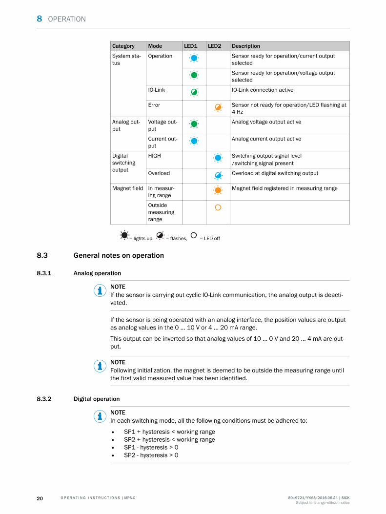
Category Mode LED1 LED2 Description
System sta‐tus
Operation Sensor ready for operation/current outputselected
Sensor ready for operation/voltage outputselected
IO-Link IO-Link connection active
Error Sensor not ready for operation/LED flashing at4 Hz
Analog out‐put
Voltage out‐put
Analog voltage output active
Current out‐put
Analog current output active
Digitalswitchingoutput
HIGH Switching output signal level/switching signal present
Overload Overload at digital switching output
Magnet field In measur‐ing range
Magnet field registered in measuring range
Outsidemeasuringrange
= lights up, = flashes, = LED off
8.3 General notes on operation
8.3.1 Analog operation
NOTEIf the sensor is carrying out cyclic IO-Link communication, the analog output is deacti‐vated.
If the sensor is being operated with an analog interface, the position values are outputas analog values in the 0 ... 10 V or 4 ... 20 mA range.
This output can be inverted so that analog values of 10 ... 0 V and 20 ... 4 mA are out‐put.
NOTEFollowing initialization, the magnet is deemed to be outside the measuring range untilthe first valid measured value has been identified.
8.3.2 Digital operation
NOTEIn each switching mode, all the following conditions must be adhered to:
• SP1 + hysteresis < working range• SP2 + hysteresis < working range• SP1 - hysteresis > 0• SP2 - hysteresis > 0
8 OPERATION
20 O P E R A T I N G I N S T R U C T I O N S | MPS-C 8019721/YYM3/2016-06-24 | SICKSubject to change without notice
8.3.2.1 Hysteresis
A hysteresis is used for the switching points in “single point”, “cylinder switch”, and“window” modes.
When the factory settings apply, the hysteresis is set to a value of 0.5 mm; however, itcan be defined as a value between 0.05 mm and 20 mm using IO-Link.
The graphics for the mode in question tell you how the hysteresis is used.
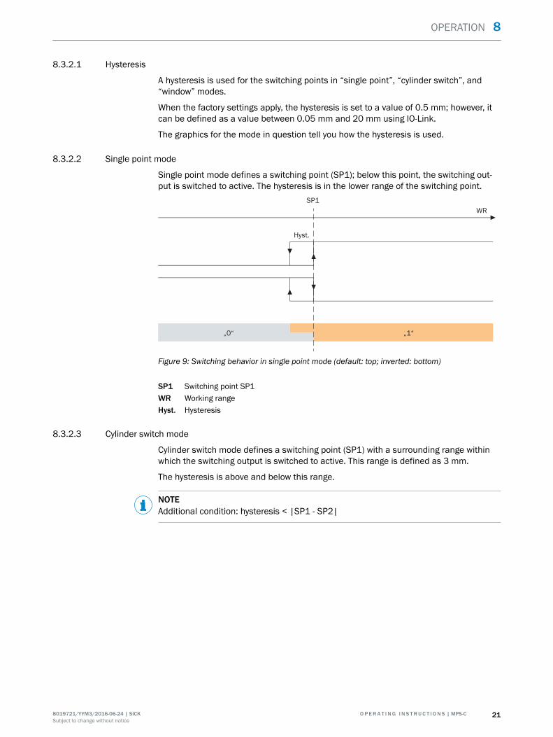
8.3.2.2 Single point mode
Single point mode defines a switching point (SP1); below this point, the switching out‐put is switched to active. The hysteresis is in the lower range of the switching point.
SP1
„0“ „1“
WR
Hyst.
Figure 9: Switching behavior in single point mode (default: top; inverted: bottom)
SP1 Switching point SP1WR Working rangeHyst. Hysteresis
8.3.2.3 Cylinder switch mode
Cylinder switch mode defines a switching point (SP1) with a surrounding range withinwhich the switching output is switched to active. This range is defined as 3 mm.
The hysteresis is above and below this range.
NOTEAdditional condition: hysteresis < |SP1 - SP2|
OPERATION 8
8019721/YYM3/2016-06-24 | SICK O P E R A T I N G I N S T R U C T I O N S | MPS-C 21Subject to change without notice
SP1
„0“„0“ „1“
WR
Hyst. Hyst.
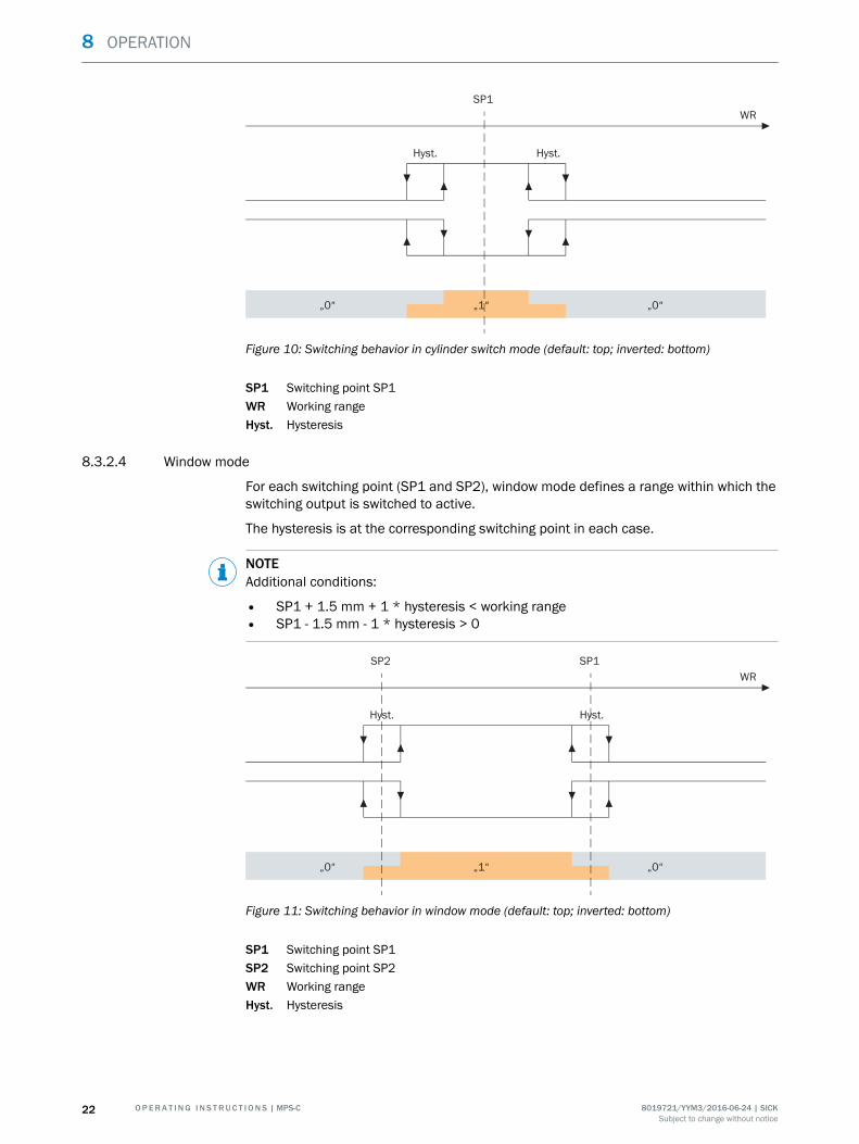
Figure 10: Switching behavior in cylinder switch mode (default: top; inverted: bottom)
SP1 Switching point SP1WR Working rangeHyst. Hysteresis
8.3.2.4 Window mode
For each switching point (SP1 and SP2), window mode defines a range within which theswitching output is switched to active.
The hysteresis is at the corresponding switching point in each case.
NOTEAdditional conditions:
• SP1 + 1.5 mm + 1 * hysteresis < working range• SP1 - 1.5 mm - 1 * hysteresis > 0
SP2 SP1
„0“„0“ „1“
WR
Hyst. Hyst.
Figure 11: Switching behavior in window mode (default: top; inverted: bottom)
SP1 Switching point SP1SP2 Switching point SP2WR Working rangeHyst. Hysteresis
8 OPERATION
22 O P E R A T I N G I N S T R U C T I O N S | MPS-C 8019721/YYM3/2016-06-24 | SICKSubject to change without notice
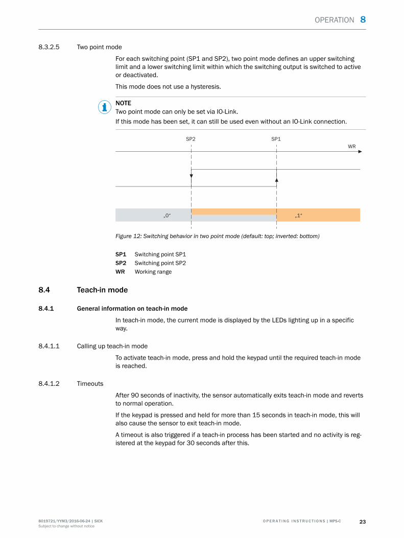
8.3.2.5 Two point mode
For each switching point (SP1 and SP2), two point mode defines an upper switchinglimit and a lower switching limit within which the switching output is switched to activeor deactivated.
This mode does not use a hysteresis.
NOTETwo point mode can only be set via IO-Link.If this mode has been set, it can still be used even without an IO-Link connection.
SP1SP2
„0“ „1“
WR
Figure 12: Switching behavior in two point mode (default: top; inverted: bottom)
SP1 Switching point SP1SP2 Switching point SP2WR Working range
8.4 Teach-in mode
8.4.1 General information on teach-in mode
In teach-in mode, the current mode is displayed by the LEDs lighting up in a specificway.
8.4.1.1 Calling up teach-in mode
To activate teach-in mode, press and hold the keypad until the required teach-in modeis reached.
8.4.1.2 Timeouts
After 90 seconds of inactivity, the sensor automatically exits teach-in mode and revertsto normal operation.
If the keypad is pressed and held for more than 15 seconds in teach-in mode, this willalso cause the sensor to exit teach-in mode.
A timeout is also triggered if a teach-in process has been started and no activity is reg‐istered at the keypad for 30 seconds after this.
OPERATION 8
8019721/YYM3/2016-06-24 | SICK O P E R A T I N G I N S T R U C T I O N S | MPS-C 23Subject to change without notice
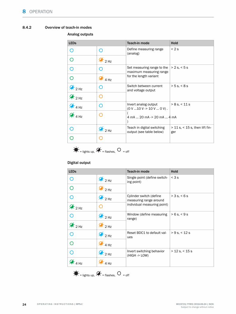
8.4.2 Overview of teach-in modes
Analog outputs
LEDs Teach-in mode Hold
Define measuring range(analog)
< 2 s
2 Hz
Set measuring range to themaximum measuring rangefor the length variant
> 2 s, < 5 s
4 Hz
2 HzSwitch between currentand voltage output
> 5 s, < 8 s
2 Hz
4 HzInvert analog output(0 V ...10 V -> 10 V ... 0 V) .(4 mA ... 20 mA -> 20 mA ... 4 mA)
> 8 s, < 11 s
4 Hz
2 HzTeach in digital switchingoutput (see table below)
> 11 s, < 15 s, then lift fin‐ger
= lights up, = flashes, = off
Digital output
LEDs Teach-in mode Hold
2 HzSingle point (define switch‐ing point)
< 3 s
2 Hz
2 HzCylinder switch (definemeasuring range aroundindividual measuring point)
> 3 s, < 6 s
2 Hz
2 HzWindow (define measuringrange)
> 6 s, < 9 s
2 Hz 2 Hz
2 HzReset BDC1 to default val‐ues
> 9 s, < 12 s
4 Hz
2 HzInvert switching behavior(HIGH -> LOW)
> 12 s, < 15 s
4 Hz 4 Hz
= lights up, = flashes, = off
8 OPERATION
24 O P E R A T I N G I N S T R U C T I O N S | MPS-C 8019721/YYM3/2016-06-24 | SICKSubject to change without notice
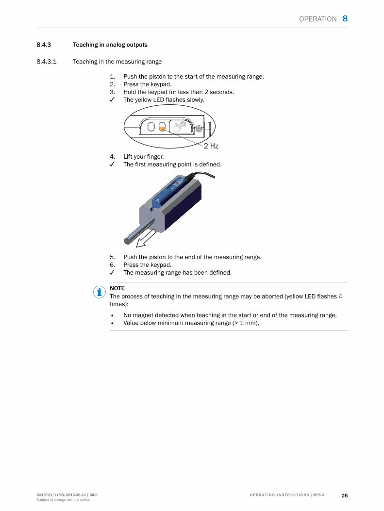
8.4.3 Teaching in analog outputs
8.4.3.1 Teaching in the measuring range
1. Push the piston to the start of the measuring range.2. Press the keypad.3. Hold the keypad for less than 2 seconds.✓ The yellow LED flashes slowly.
2 Hz
4. Lift your finger.✓ The first measuring point is defined.
5. Push the piston to the end of the measuring range.6. Press the keypad.✓ The measuring range has been defined.
NOTEThe process of teaching in the measuring range may be aborted (yellow LED flashes 4times):
• No magnet detected when teaching in the start or end of the measuring range.• Value below minimum measuring range (> 1 mm).
OPERATION 8
8019721/YYM3/2016-06-24 | SICK O P E R A T I N G I N S T R U C T I O N S | MPS-C 25Subject to change without notice
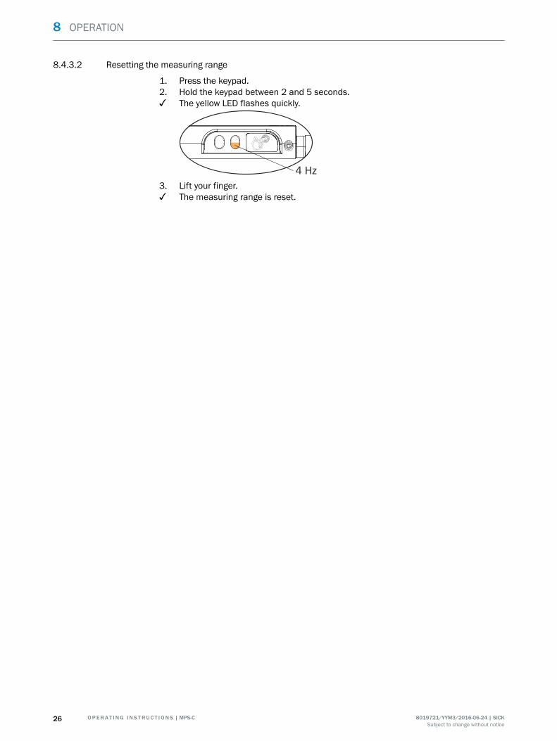
8.4.3.2 Resetting the measuring range
1. Press the keypad.2. Hold the keypad between 2 and 5 seconds.✓ The yellow LED flashes quickly.
4 Hz
3. Lift your finger.✓ The measuring range is reset.
8 OPERATION
26 O P E R A T I N G I N S T R U C T I O N S | MPS-C 8019721/YYM3/2016-06-24 | SICKSubject to change without notice
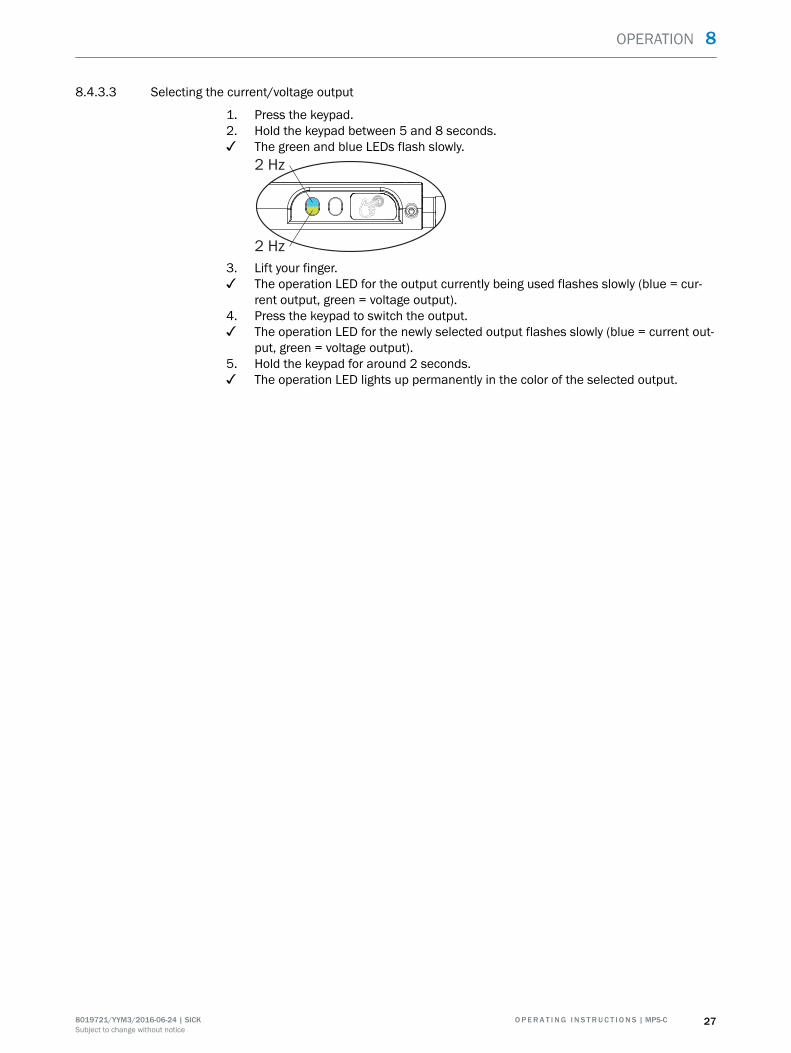
8.4.3.3 Selecting the current/voltage output
1. Press the keypad.2. Hold the keypad between 5 and 8 seconds.✓ The green and blue LEDs flash slowly.
2 Hz
2 Hz
3. Lift your finger.✓ The operation LED for the output currently being used flashes slowly (blue = cur‐
rent output, green = voltage output).4. Press the keypad to switch the output.✓ The operation LED for the newly selected output flashes slowly (blue = current out‐
put, green = voltage output).5. Hold the keypad for around 2 seconds.✓ The operation LED lights up permanently in the color of the selected output.
OPERATION 8
8019721/YYM3/2016-06-24 | SICK O P E R A T I N G I N S T R U C T I O N S | MPS-C 27Subject to change without notice
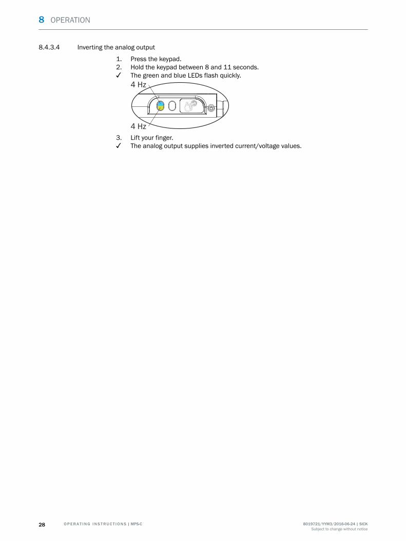
8.4.3.4 Inverting the analog output
1. Press the keypad.2. Hold the keypad between 8 and 11 seconds.✓ The green and blue LEDs flash quickly.
4 Hz
4 Hz
3. Lift your finger.✓ The analog output supplies inverted current/voltage values.
8 OPERATION
28 O P E R A T I N G I N S T R U C T I O N S | MPS-C 8019721/YYM3/2016-06-24 | SICKSubject to change without notice
8.4.4 Teaching in the digital switching output
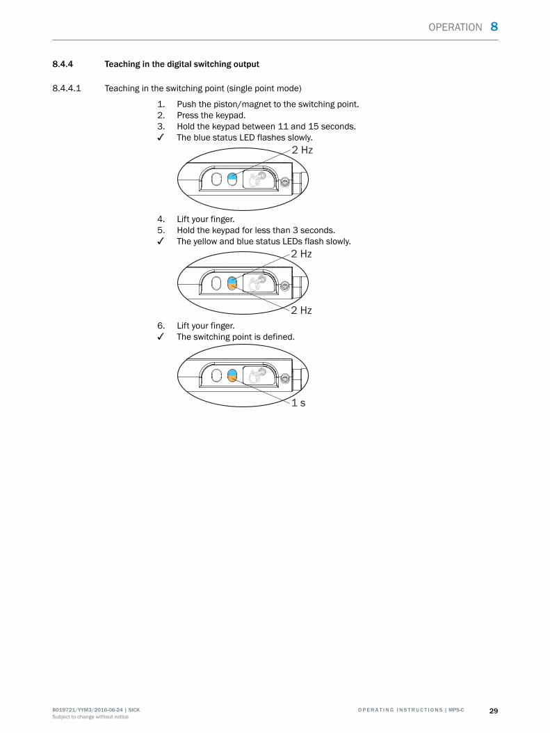
8.4.4.1 Teaching in the switching point (single point mode)
1. Push the piston/magnet to the switching point.2. Press the keypad.3. Hold the keypad between 11 and 15 seconds.✓ The blue status LED flashes slowly.
2 Hz
4. Lift your finger.5. Hold the keypad for less than 3 seconds.✓ The yellow and blue status LEDs flash slowly.
2 Hz
2 Hz
6. Lift your finger.✓ The switching point is defined.
1 s
OPERATION 8
8019721/YYM3/2016-06-24 | SICK O P E R A T I N G I N S T R U C T I O N S | MPS-C 29Subject to change without notice
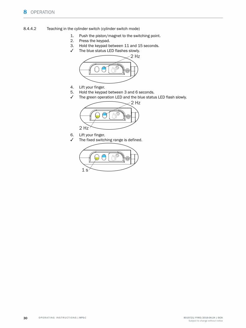
8.4.4.2 Teaching in the cylinder switch (cylinder switch mode)
1. Push the piston/magnet to the switching point.2. Press the keypad.3. Hold the keypad between 11 and 15 seconds.✓ The blue status LED flashes slowly.
2 Hz
4. Lift your finger.5. Hold the keypad between 3 and 6 seconds.✓ The green operation LED and the blue status LED flash slowly.
2 Hz
2 Hz
6. Lift your finger.✓ The fixed switching range is defined.
1 s
8 OPERATION
30 O P E R A T I N G I N S T R U C T I O N S | MPS-C 8019721/YYM3/2016-06-24 | SICKSubject to change without notice
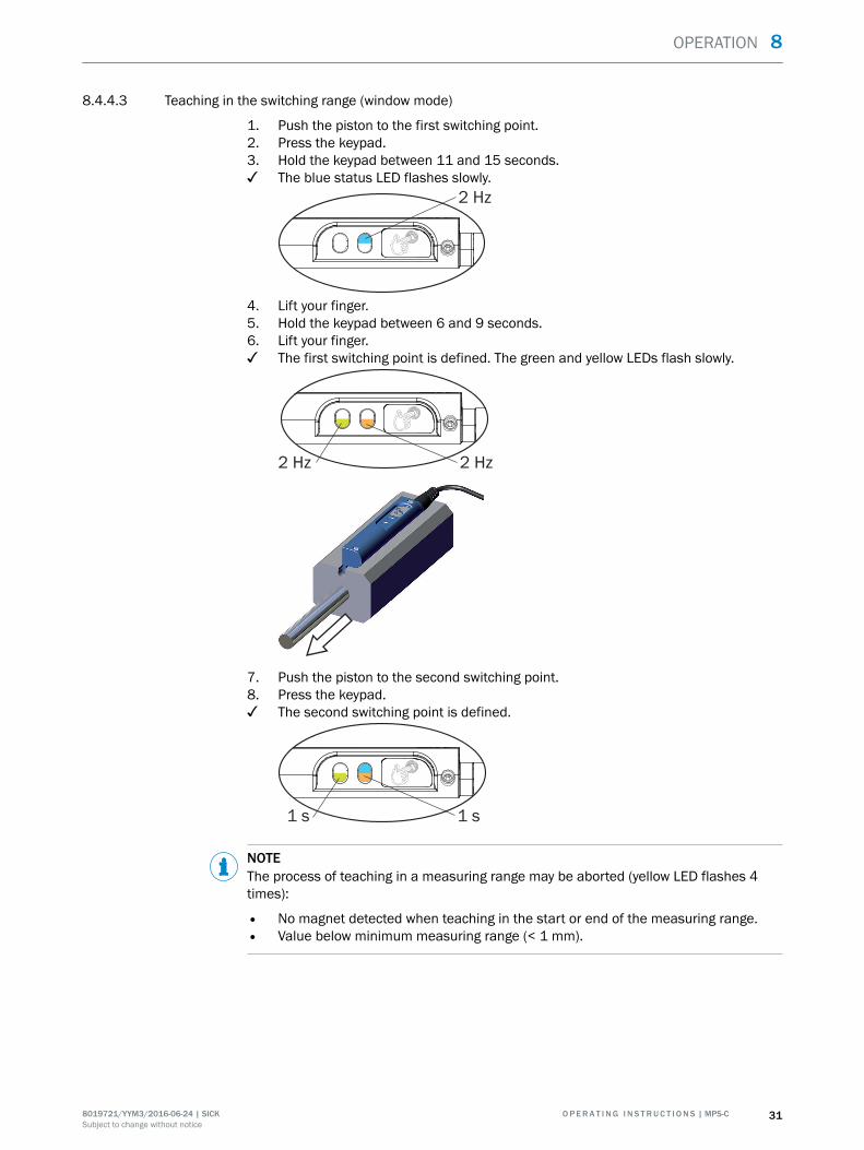
8.4.4.3 Teaching in the switching range (window mode)
1. Push the piston to the first switching point.2. Press the keypad.3. Hold the keypad between 11 and 15 seconds.✓ The blue status LED flashes slowly.
2 Hz
4. Lift your finger.5. Hold the keypad between 6 and 9 seconds.6. Lift your finger.✓ The first switching point is defined. The green and yellow LEDs flash slowly.
2 Hz 2 Hz
7. Push the piston to the second switching point.8. Press the keypad.✓ The second switching point is defined.
1 s 1 s
NOTEThe process of teaching in a measuring range may be aborted (yellow LED flashes 4times):
• No magnet detected when teaching in the start or end of the measuring range.• Value below minimum measuring range (< 1 mm).
OPERATION 8
8019721/YYM3/2016-06-24 | SICK O P E R A T I N G I N S T R U C T I O N S | MPS-C 31Subject to change without notice
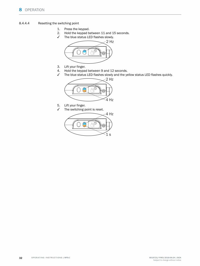
8.4.4.4 Resetting the switching point
1. Press the keypad.2. Hold the keypad between 11 and 15 seconds.✓ The blue status LED flashes slowly.
2 Hz
3. Lift your finger.4. Hold the keypad between 9 and 12 seconds.✓ The blue status LED flashes slowly and the yellow status LED flashes quickly.
4 Hz
2 Hz
5. Lift your finger.✓ The switching point is reset.
1 s
4 Hz
8 OPERATION
32 O P E R A T I N G I N S T R U C T I O N S | MPS-C 8019721/YYM3/2016-06-24 | SICKSubject to change without notice
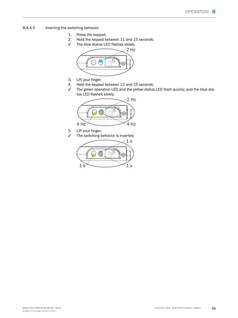
8.4.4.5 Inverting the switching behavior
1. Press the keypad.2. Hold the keypad between 11 and 15 seconds.✓ The blue status LED flashes slowly.
2 Hz
3. Lift your finger.4. Hold the keypad between 12 and 15 seconds.✓ The green operation LED and the yellow status LED flash quickly, and the blue sta‐
tus LED flashes slowly.
4 Hz 4 Hz
2 Hz
5. Lift your finger.✓ The switching behavior is inverted.
1 s 1 s
1 s
OPERATION 8
8019721/YYM3/2016-06-24 | SICK O P E R A T I N G I N S T R U C T I O N S | MPS-C 33Subject to change without notice
9 Maintenance
9.1 Maintenance
The sensor is maintenance-free.
To ensure it continues operating without problems, however, the screw connectionbetween the sensor and the slot, and for the electrical connection, should be checkedregularly. The interval at which they are checked should be adapted in line with the con‐ditions of the application, but should be no more than 6 months.
9.2 Repairs
Repairs on the sensor may only be carried out by the manufacturer. Any interruption ormodification of the sensor will invalidate the manufacturer warranty.
9 MAINTENANCE
34 O P E R A T I N G I N S T R U C T I O N S | MPS-C 8019721/YYM3/2016-06-24 | SICKSubject to change without notice

10 Decommissioning
Removing the sensor
1. Switch off the supply voltage to the sensor.2. Detach all connecting cables from the sensor.3. If the sensor is being replaced, mark its position and alignment on the bracket or
surroundings.4. Remove the sensor from the slot.
Disposing of the sensor
Any sensor which can no longer be used must be disposed of in an environmentallyfriendly manner in accordance with the applicable country-specific waste disposal regu‐lations. The sensor is electronic waste and must under no circumstances be disposedof with general waste.
DECOMMISSIONING 10
8019721/YYM3/2016-06-24 | SICK O P E R A T I N G I N S T R U C T I O N S | MPS-C 35Subject to change without notice
11 Technical data
11.1 Performance
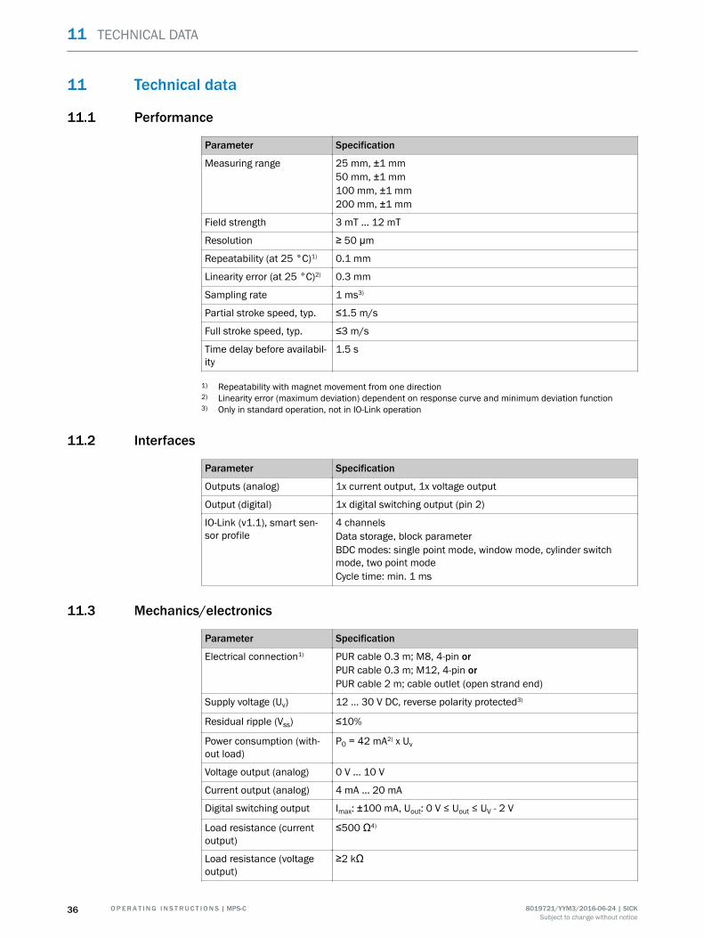
Parameter Specification
Measuring range 25 mm, ±1 mm50 mm, ±1 mm100 mm, ±1 mm200 mm, ±1 mm
Field strength 3 mT ... 12 mT
Resolution ≥ 50 μm
Repeatability (at 25 °C)1) 0.1 mm
Linearity error (at 25 °C)2) 0.3 mm
Sampling rate 1 ms3)
Partial stroke speed, typ. ≤1.5 m/s
Full stroke speed, typ. ≤3 m/s
Time delay before availabil‐ity
1.5 s
1) Repeatability with magnet movement from one direction2) Linearity error (maximum deviation) dependent on response curve and minimum deviation function3) Only in standard operation, not in IO-Link operation
11.2 Interfaces
Parameter Specification
Outputs (analog) 1x current output, 1x voltage output
Output (digital) 1x digital switching output (pin 2)
IO-Link (v1.1), smart sen‐sor profile
4 channelsData storage, block parameterBDC modes: single point mode, window mode, cylinder switchmode, two point modeCycle time: min. 1 ms
11.3 Mechanics/electronics
Parameter Specification
Electrical connection1) PUR cable 0.3 m; M8, 4-pin orPUR cable 0.3 m; M12, 4-pin orPUR cable 2 m; cable outlet (open strand end)
Supply voltage (Uv) 12 ... 30 V DC, reverse polarity protected3)
Residual ripple (Vss) ≤10%
Power consumption (with‐out load)
P0 = 42 mA2) x Uv
Voltage output (analog) 0 V ... 10 V
Current output (analog) 4 mA ... 20 mA
Digital switching output Imax: ±100 mA, Uout: 0 V ≤ Uout ≤ UV - 2 V
Load resistance (currentoutput)
≤500 Ω4)
Load resistance (voltageoutput)
≥2 kΩ
11 TECHNICAL DATA
36 O P E R A T I N G I N S T R U C T I O N S | MPS-C 8019721/YYM3/2016-06-24 | SICKSubject to change without notice
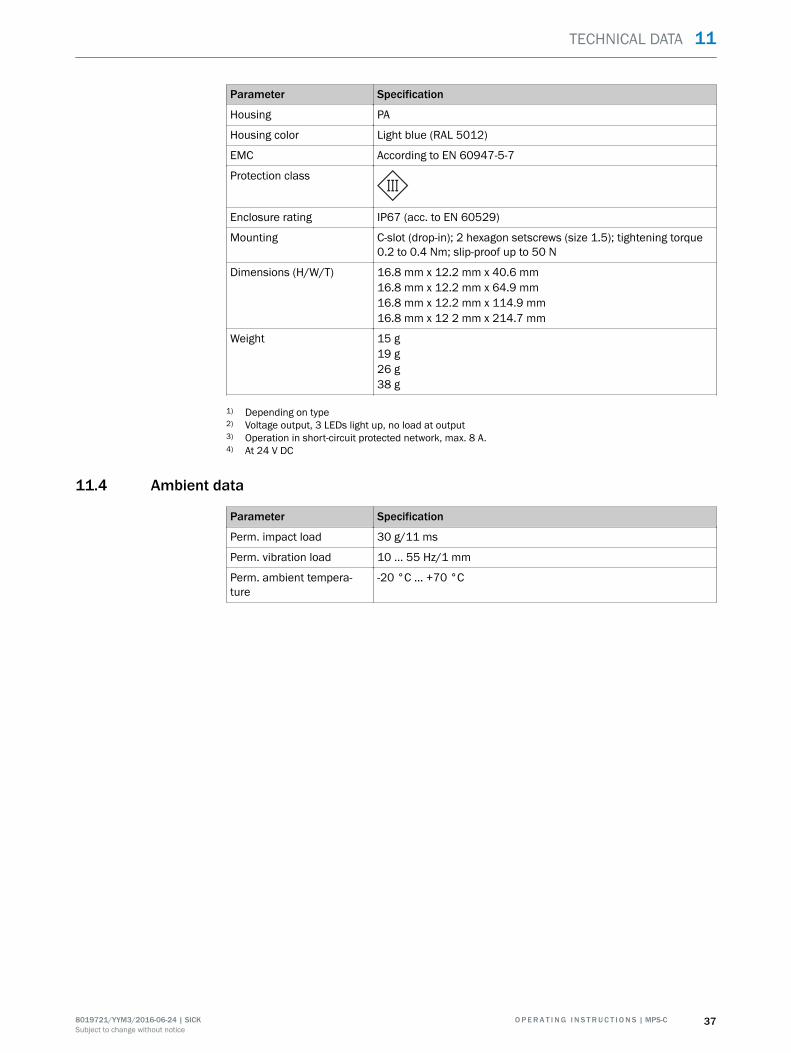
Parameter Specification
Housing PA
Housing color Light blue (RAL 5012)
EMC According to EN 60947-5-7
Protection class
Enclosure rating IP67 (acc. to EN 60529)
Mounting C-slot (drop-in); 2 hexagon setscrews (size 1.5); tightening torque0.2 to 0.4 Nm; slip-proof up to 50 N
Dimensions (H/W/T) 16.8 mm x 12.2 mm x 40.6 mm16.8 mm x 12.2 mm x 64.9 mm16.8 mm x 12.2 mm x 114.9 mm16.8 mm x 12 2 mm x 214.7 mm
Weight 15 g19 g26 g38 g
1) Depending on type2) Voltage output, 3 LEDs light up, no load at output3) Operation in short-circuit protected network, max. 8 A.4) At 24 V DC
11.4 Ambient data
Parameter Specification
Perm. impact load 30 g/11 ms
Perm. vibration load 10 ... 55 Hz/1 mm
Perm. ambient tempera‐ture
-20 °C ... +70 °C
TECHNICAL DATA 11
8019721/YYM3/2016-06-24 | SICK O P E R A T I N G I N S T R U C T I O N S | MPS-C 37Subject to change without notice

12 Annex
12.1 EU declaration of conformity
The EU declaration of conformity can be downloaded from the Internet at:
b www.sick.com/mps-c
12 ANNEX
38 O P E R A T I N G I N S T R U C T I O N S | MPS-C 8019721/YYM3/2016-06-24 | SICKSubject to change without notice

ANNEX 12
8019721/YYM3/2016-06-24 | SICK O P E R A T I N G I N S T R U C T I O N S | MPS-C 39Subject to change without notice
AustraliaPhone +61 3 9457 0600 1800 334 802 – tollfreeE-Mail [email protected]
AustriaPhone +43 22 36 62 28 8-0E-Mail [email protected]
Belgium/LuxembourgPhone +32 2 466 55 66E-Mail [email protected]
BrazilPhone +55 11 3215-4900E-Mail [email protected]
CanadaPhone +1 905 771 14 44E-Mail [email protected]
Czech RepublicPhone +420 2 57 91 18 50E-Mail [email protected]
ChilePhone +56 2 2274 7430E-Mail [email protected]
ChinaPhone +86 20 2882 3600E-Mail [email protected]
DenmarkPhone +45 45 82 64 00E-Mail [email protected]
FinlandPhone +358-9-2515 800E-Mail [email protected]
FrancePhone +33 1 64 62 35 00E-Mail [email protected]
GermanyPhone +49 211 5301-301E-Mail [email protected]
Hong KongPhone +852 2153 6300E-Mail [email protected]
HungaryPhone +36 1 371 2680E-Mail [email protected]
IndiaPhone +91 22 4033 8333E-Mail [email protected]
IsraelPhone +972 4 6881000E-Mail [email protected]
ItalyPhone +39 02 274341E-Mail [email protected]
JapanPhone +81 3 5309 2112E-Mail [email protected]
MalaysiaPhone +6 03 8080 7425E-Mail [email protected]
MexicoPhone +52 472 748 9451E-Mail [email protected]
NetherlandsPhone +31 30 2044 000E-Mail [email protected]
New Zealand Phone +64 9 415 0459 0800 222 278 – tollfreeE-Mail [email protected]
Norway Phone +47 67 81 50 00E-Mail [email protected]
PolandPhone +48 22 539 41 00E-Mail [email protected]
RomaniaPhone +40 356 171 120 E-Mail [email protected]
RussiaPhone +7 495 775 05 30E-Mail [email protected]
SingaporePhone +65 6744 3732E-Mail [email protected]
SlovakiaPhone +421 482 901201E-Mail [email protected]
SloveniaPhone +386 591 788 49E-Mail [email protected]
South AfricaPhone +27 11 472 3733E-Mail [email protected]
South KoreaPhone +82 2 786 6321E-Mail [email protected]
SpainPhone +34 93 480 31 00E-Mail [email protected]
SwedenPhone +46 10 110 10 00E-Mail [email protected]
SwitzerlandPhone +41 41 619 29 39E-Mail [email protected]
TaiwanPhone +886 2 2375-6288E-Mail [email protected]
ThailandPhone +66 2645 0009E-Mail [email protected]
TurkeyPhone +90 216 528 50 00E-Mail [email protected]
United Arab EmiratesPhone +971 4 88 65 878E-Mail [email protected]
United KingdomPhone +44 1727 831121E-Mail [email protected]
USAPhone +1 800 325 7425 E-Mail [email protected]
VietnamPhone +84 945452999E-Mail [email protected]
Further locations at www.sick.com
SICK AG | Waldkirch | Germany | www.sick.com
8019
721/
YYM
3/20
16-0
6-24
/en/
COM
AT