Embed Size (px)
Citation preview
BA 33.0003!R;]
Ä!R;]ä
Operating Instructions
Motors
MDSLS servo spindle motors
BA 33.0003 1.0 04/2004 TD09 2004
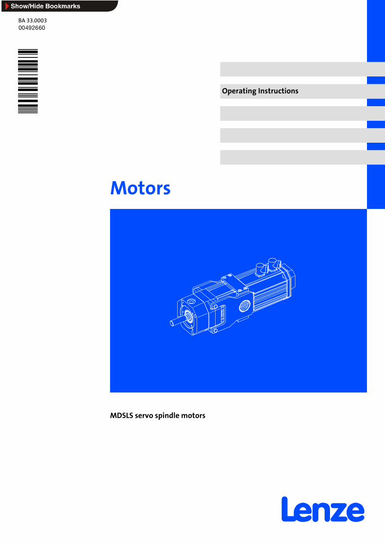
Structure of type code for servo spindle motors
MD -
Current type D = three-phase current
Cooling type/ventilation S = Self-cooled (cooling via convection and radiation)
Design/housing L = Compact servo motor with integrated linear feed
Machine type S = Synchronous machine
Built-on accessories AG = Absolute value encoderBA = Brake and SinCos absolute value encoder or SSI absolute value encoderBG = Brake, resolver and incremental encoderBI = Brake and incremental encoder (pulse encoder)BR = BrakeBS = Brake and resolverBW = Brake, resolver and absolute value encoderBX = Brake, encoder preparedGX = No brake, encoder preparedNN = No brake, no encoderIG = Incremental encoder (pulse encoder)RA = Resolver and absolute value encoderRI = Resolver and incremental encoderRS = Resolver
Frame size
Overall length
Number of pole pairs
Specification ” ” = Standard”U” = UL design, UR certificate
BA 33.0003 1.0 04/2004 TD09 2004
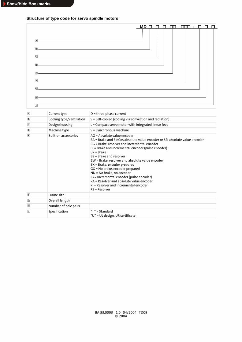
Nameplate of servo spindle motor
1 2
6
13
12 9
4 5
317
18
16
21
22
15
8714
23 2221 mmFN /kN
19
No. Explanation No. Explanation
1 Motor type: three-phase ACmotor 13 Rated voltage UN [V]
2 Lenze motor type 14 Rated torqueMN [Nm]
3 ID no. 15 Labelling of thermal detector
4 Enclosure 16 Data for holding brake: voltage, current, torque
5 Thermal class 17 Labelling of encoder 1)
6 Rated current IN [A] 18 Motor no.
7 Rated frequency fN[Hz] 19Selection number for operation at servo inverters ofseries 9300 2)
8 Rated speed nN [min-1] 21 Rated load
9 Continuous standstill torqueM0 [Nm] 22 Lead
12 Rated power PN [kW] 23 Lift
1) RS1 - Lenze-specific resolver (1 pair of poles)RS3 - KUKA-specific resolver (3 pairs of poles)
2) For operation with servo inverters of series 9300:In C0086 or GDC (Global Drive Control software), enter the specified selection number to automatically optimise the control mode.
What is new / what has changed in the Operating Instructions?
Material number Edition Important Contents
00 492 660 1.0 04/04 TD09 1st edition First printing
© 2004 Lenze Drive Systems GmbH, Hans-Lenze-Straße 1, 31855 AerzenNo part of this documentation may be reproduced or made accessible to third parties without written consent by Lenze DriveSystems GmbH.All information given in this documentation has been selected carefully and complies with the hardware and softwaredescribed. Nevertheless, deviations cannot be ruled out. We do not take any responsibility or liability for damages which mightpossibly occur. Necessary corrections will be included in subsequent editions.
Contentsi
4 BA 33.0003 EN 1.0
1 Preface and general information 6. . . . . . . . . . . . . . . . . . . . . . . . . . . . . . . . . . . . . . . . . . . .
1.1 About these Operating Instructions 6. . . . . . . . . . . . . . . . . . . . . . . . . . . . . . . . . . . . .
1.2 Terminology used 6. . . . . . . . . . . . . . . . . . . . . . . . . . . . . . . . . . . . . . . . . . . . . . . . . . . .
1.3 Scope of supply 6. . . . . . . . . . . . . . . . . . . . . . . . . . . . . . . . . . . . . . . . . . . . . . . . . . . . . .
1.4 Legal regulations 7. . . . . . . . . . . . . . . . . . . . . . . . . . . . . . . . . . . . . . . . . . . . . . . . . . . . .
2 Safety 8. . . . . . . . . . . . . . . . . . . . . . . . . . . . . . . . . . . . . . . . . . . . . . . . . . . . . . . . . . . . . . . . . . .
2.1 General safety and application notes for Lenze motors 8. . . . . . . . . . . . . . . . . . . . .
2.2 General safety and application notes for Lenze controllers 10. . . . . . . . . . . . . . . . . .
2.3 Residual hazards 13. . . . . . . . . . . . . . . . . . . . . . . . . . . . . . . . . . . . . . . . . . . . . . . . . . . . .
2.4 Definition of notes used 13. . . . . . . . . . . . . . . . . . . . . . . . . . . . . . . . . . . . . . . . . . . . . . .
3 Technical data 15. . . . . . . . . . . . . . . . . . . . . . . . . . . . . . . . . . . . . . . . . . . . . . . . . . . . . . . . . . . .
3.1 General data/operating conditions 15. . . . . . . . . . . . . . . . . . . . . . . . . . . . . . . . . . . . . .
3.2 Rated data 16. . . . . . . . . . . . . . . . . . . . . . . . . . . . . . . . . . . . . . . . . . . . . . . . . . . . . . . . . .
3.3 Holding brake (option) 17. . . . . . . . . . . . . . . . . . . . . . . . . . . . . . . . . . . . . . . . . . . . . . . .
3.3.1 Spring-operated brakes 18. . . . . . . . . . . . . . . . . . . . . . . . . . . . . . . . . . . . . . . .
4 Mechanical installation 19. . . . . . . . . . . . . . . . . . . . . . . . . . . . . . . . . . . . . . . . . . . . . . . . . . . . .
4.1 Transport, storage and installation 19. . . . . . . . . . . . . . . . . . . . . . . . . . . . . . . . . . . . . .
4.2 Assembly of built-on accessories 19. . . . . . . . . . . . . . . . . . . . . . . . . . . . . . . . . . . . . . . .
4.3 Connection of external lubricant unit 20. . . . . . . . . . . . . . . . . . . . . . . . . . . . . . . . . . . .
4.4 Motor support 21. . . . . . . . . . . . . . . . . . . . . . . . . . . . . . . . . . . . . . . . . . . . . . . . . . . . . . .
4.5 Bellows 21. . . . . . . . . . . . . . . . . . . . . . . . . . . . . . . . . . . . . . . . . . . . . . . . . . . . . . . . . . . . .
5 Electrical installation 22. . . . . . . . . . . . . . . . . . . . . . . . . . . . . . . . . . . . . . . . . . . . . . . . . . . . . . .
5.1 Important notes 22. . . . . . . . . . . . . . . . . . . . . . . . . . . . . . . . . . . . . . . . . . . . . . . . . . . . . .
5.1.1 EMC-compliant wiring 24. . . . . . . . . . . . . . . . . . . . . . . . . . . . . . . . . . . . . . . . .5.1.2 Wiring diagrams for servo spindlemotors MDSLS 24. . . . . . . . . . . . . . . . . .
6 Commissioning 26. . . . . . . . . . . . . . . . . . . . . . . . . . . . . . . . . . . . . . . . . . . . . . . . . . . . . . . . . . .
6.1 Before switching on 29. . . . . . . . . . . . . . . . . . . . . . . . . . . . . . . . . . . . . . . . . . . . . . . . . .
6.2 Functional test 29. . . . . . . . . . . . . . . . . . . . . . . . . . . . . . . . . . . . . . . . . . . . . . . . . . . . . .
6.3 Motor connection 30. . . . . . . . . . . . . . . . . . . . . . . . . . . . . . . . . . . . . . . . . . . . . . . . . . . .
6.3.1 Lenze standard power terminal 30. . . . . . . . . . . . . . . . . . . . . . . . . . . . . . . . .
6.3.2 Lenze standard resolver connection 30. . . . . . . . . . . . . . . . . . . . . . . . . . . . .6.3.3 Connection of SinCos encoder 30. . . . . . . . . . . . . . . . . . . . . . . . . . . . . . . . . .
Contents i
5BA 33.0003 EN 1.0
7 During operation 31. . . . . . . . . . . . . . . . . . . . . . . . . . . . . . . . . . . . . . . . . . . . . . . . . . . . . . . . . .
8 Troubleshooting and fault elimination 32. . . . . . . . . . . . . . . . . . . . . . . . . . . . . . . . . . . . . . .
9 Maintenance/repair 34. . . . . . . . . . . . . . . . . . . . . . . . . . . . . . . . . . . . . . . . . . . . . . . . . . . . . . .
9.1 Maintenance intervals 34. . . . . . . . . . . . . . . . . . . . . . . . . . . . . . . . . . . . . . . . . . . . . . . .
9.2 Maintenance operations 34. . . . . . . . . . . . . . . . . . . . . . . . . . . . . . . . . . . . . . . . . . . . . . .
9.2.1 Adjustment of resolver for synchronous servo motors 34. . . . . . . . . . . . . .
9.2.2 Temperature control for servo motors 35. . . . . . . . . . . . . . . . . . . . . . . . . . . .9.2.3 Lubricant change 35. . . . . . . . . . . . . . . . . . . . . . . . . . . . . . . . . . . . . . . . . . . . .
9.2.4 Clearing device 36. . . . . . . . . . . . . . . . . . . . . . . . . . . . . . . . . . . . . . . . . . . . . . .
9.3 Repair 36. . . . . . . . . . . . . . . . . . . . . . . . . . . . . . . . . . . . . . . . . . . . . . . . . . . . . . . . . . . . . .
10 Appendix 37. . . . . . . . . . . . . . . . . . . . . . . . . . . . . . . . . . . . . . . . . . . . . . . . . . . . . . . . . . . . . . . .
10.1 Manufacturer’s Certification 37. . . . . . . . . . . . . . . . . . . . . . . . . . . . . . . . . . . . . . . . . . .
10.2 EC Declaration of Conformity ’96 39. . . . . . . . . . . . . . . . . . . . . . . . . . . . . . . . . . . . . . . .
Preface and general informationScope of supply
1
6 BA 33.0003 EN 1.0
1 Preface and general information
1.1 About these Operating Instructions
ƒ The present operating instructions are intended for safe working on and with servospindle motors of type MDSLS. They contain safety instructions that must beobserved.
ƒ All personnel working at and with the servo spindle motors listed must have theoperating instructions available and observe the information and notes importantfor them.
ƒ The operating instructions must always be complete and perfectly readable.
ƒ If the information in these operating instructions is not sufficient for your case,please consult the operating instructions of the drive controllers.
1.2 Terminology used
Term Used in the following text for
Motor Servo spindle motor type MDSLS
Drive controller Any servo inverter of series 9300, ECS
Drive system Servo inverter with servo spindle motor and other Lenze drive components
1.3 Scope of supply
The drive systems are individually grouped. After receipt of the supply, check immediatelywhether it correspondswith theaccompanyingpapers. Lenzedoes notgrant anywarrantyfor subsequent claims.
Claim for
ƒ visible transport damages immediately to the forwarder.
ƒ visible deficiencies / incomplete deliveries immediately to your Lenze representative.
Preface and general informationLegal regulations
1
7BA 33.0003 EN 1.0
1.4 Legal regulations
Labelling Nameplate CE designation Manufacturerg
Lenze motors are uniquelydesignated by the content of thenameplate.
Conforming to EC ”Low-VoltageDirective”
Lenze Drive Systems GmbHPostfach 10 13 52D-31763 Hameln
Application asdirected
Servo spindle motors type MDSLSmust only be operated under the operating conditions prescribed in these instructions.are components:– for use as small drives.– for installation in a machine.– for assembly with other components into a machine.meet the protection requirements of the EC ”Low-Voltage Directive”.are not machines in the sense of the EC Machine Directive.are not household appliances, but as components solely intended for further application for commercial use.
Drive systems with servo spindle motor type MDSLSmeet the EC Directive ”Electromagnetic compatibility” if they are installed according to the specifications ofthe CE-typical drive system.are applicable:– in public and non-public mains.– in industrial as well as residential areas.The end user is responsible for adhering to the EC directives in the machine application.
Any other use is considered unintended!
Liability The information, data, and notes in these instructions were state of the art at the time of printing. Claimsreferring to motors which have already been supplied cannot be derived from the information, illustrations,and descriptions.The process-related notes and circuit sections used in these instructions are suggestions whose suitability forthe respective application must be checked. Lenze assumes no guarantee for the suitability of the listedprocedures and circuit samples.The information in these instructions describes the features of the products without assuring them.No liability is accepted for damages and malfunctions caused by:– disregarding the operating instructions– unauthorised modifications to the motors– operating mistakes– improper working at and with the motors.
Warranty Conditions of warranty: see terms of sale and delivery of Lenze Drive Systems GmbH.Warranty claims must be made to Lenze immediately after detecting the deficiency or fault.The warranty is void where liability claims cannot be made.
Disposal Material Recycle Disposep
Metal D -
Plastic D -
Assembled PCBs - D
SafetyGeneral safety and application notes for Lenze motors
2
8 BA 33.0003 EN 1.0
2 Safety
2.1 General safety and application notes for Lenze motors
(to: Low-Voltage Directive 73/23/EEC)
General
Low-voltage machines have dangerous, live and rotating parts as well as possibly hotsurfaces. All operations serving transport, connection, commissioning and maintenanceare to be carried out by qualified, skilled personnel (observe EN 50110-1 (VDE 0105-100);IEC 60364). Improper handlingmay cause severe injury to persons or damage tomaterialassets.
Synchronous machines induce voltages at open terminals during operation.
Application as directed
These low-voltage machines are intended for industrial and commercial installations.They complywith theharmonizedstandardsof theEN 60034 (VDEO53O) series. Their usein hazardous areas is prohibited unless they are expressly intended for such use (followadditional instructions).
Degrees of protection ≤ IP23 are only intended for outdoor use when applying specialprotective measures. Air-cooled designs are rated for ambient temperatures from -15 °Cand -10 °C to +40 °C and altitudes ≤ 1000m a.m.s.l., from -20 °C to +40 °C without brakeor with spring-operated brake, non-ventilated or with integral fan, from -15 °C to +40 °Cwith permanent magnet brake and from -10 °C to +40 °C with separate fan. Checkindications on the nameplate and if they are different, observe them. The conditions onsite must correspond to all nameplate data.
Low-voltagemachinesarecomponents for the installation intomachinesasdefined intheMachinery Directive 98/37/EC. Commissioning is prohibited until the conformity of theend product with this Directive has been established (follow a.o. EN 60204-1).
The integrated brakes cannot be used as safety brakes. It cannot be guaranteed thatfactors which cannot be influenced, such as oil ingression because of a defective A-sideshaft seal, do not cause a torque reduction.
Transport, storage
The forwarder must be informed directly after receipt of the goods about all damages ordeficiencies; if necessary, commissioningmust be stopped. Tighten screwed-in ring boltsbefore transport. They are designed for the weight of the low-voltage machine, do notapply extra loads. If necessary, use suitable and adequately dimensioned means oftransport (e.g. rope guides).
Removetheshippingbracesbeforecommissioning. Reuse themfor further transports. Forstorage of low-voltage machines ensure a dry, dust-free and low-vibration (vrms ≤ 0.2mm/s) environment (damage while being stored). Measure the insulation resistancebefore commissioning. If the values are ≤ 1 kΩ per volt of rated voltage, dry the winding.
SafetyGeneral safety and application notes for Lenze motors
2
9BA 33.0003 EN 1.0
Installation
Ensureanevensurface, solidfootor flangemountingandexactalignment ifadirectclutchis connected.Avoid resonanceswith the rotational frequencyanddoublemains frequencywhich may be caused during assembly. Turn rotor by hand, listen for unusual slippingnoises. Check the direction of rotation when the clutch is not active (observe section 5).
Useappropriate tools tomountor removebeltpulleysandclutches (heatgeneration!) andcover them with a touch guard. Impermissible belt tensions must be avoided (technicallist).
Themachinesarehalf-keybalanced. The clutchmustbehalf-keybalanced, too. Thevisibleoutstanding part of the key must be removed.
If required, providepipe connections.Designswith shaft endatbottommustbeprotectedwithacoverwhichpreventsthe ingressionofforeignparticles into thefan. Freecirculationof the coolingairmustbeensured. Theexhaustair - also theexhaust air of othermachinesnext to the drive system - must not be taken in again immediately.
Electrical connection
All operations must only be carried out by qualified and skilled personnel when thelow-voltagemachine is at standstill andwhen themachine is de-energized andprotectedagainst unintentional restart. This also applies to auxiliary circuits (e.g. brake, encoder,separate fan).
Check safe isolation from the supply!
If the tolerances in EN 60034-1; IEC 34 (VDE 0530-1) - voltage ±5%, frequency ±2%,waveform, symmetry - are exceeded, more heat will be generated and the electromagneticcompatibility will be influenced.
Observe the indications on the nameplate, operating notes, and the connection diagramin the terminal box.
The connectionmust ensure a continuous and safe electrical supply (no loose wire ends);use appropriate cable terminals. The connection to the PE conductor must be safe. Theplug-in connector must be bolt tightly (to stop).
The clearances between blank, live parts and earthmust not fall below 8mmat V r ≤ 550V, 10 mm at Vr ≤ 725 V, 14 mm at Vr ≤ 1000 V.
The terminal box must be clean and dry; foreign particles, dirt and moisture disturboperation. All unused cable entries and the box itself must be sealed against dust andwater. For the trial run without output elements, lock the key. Check brake operationbefore commissioning of low-voltage machines with brakes.
SafetyGeneral safety and application notes for Lenze controllers
2
10 BA 33.0003 EN 1.0
Operation
Vibration severities vrms≤3.5mm/s (Pr≤15 kW)and4.5mm/s (Pr > 15 kW) are acceptablewhen the clutch is activated. If deviations from normal operation occur, e.g. increasedtemperatures, noises, vibrations, find the cause and, if necessary, contact themanufacturer. Switch off the machine in problematic situations.
If the drive is exposed to dirt, clean it regularly.
Do not switch off the protection devices, not even for trial runs.
Integrated temperature sensors do not provide full protection. If necessary, limit themaximum current. Connect the function blocks such that the machine switches off afterseveral seconds of operation at I > I r, especially if blocking may occur.
Shaft seals and bearings have a limited service life.
Regrease the bearings using the relubrication facility while the low-voltage machine isrunning. Observe the saponification number. If the grease drain hole is sealedwith a plug(IP54 driven end; IP23 driven end and non-driven end), remove the plug beforecommissioning. Seal the bore holes with grease. Replace the prelubricated bearings (2Zbearings) after approx. 10,000h -20,000h, at the latest however after 3 - 4 years.Observethe manufacturer’s instructions.
2.2 General safety and application notes for Lenze controllers
(to: Low-Voltage Directive 73/23/EEC)
General
Depending on their degree of protection, some parts of Lenze controllers (frequencyinverters, servo inverters, DC controllers) and their accessory components can be live,moving and rotating during operation. Surfaces can be hot.
Non-authorized removal of the required cover, inappropriate use, incorrect installationoroperation, creates the risk of severe injury to persons or damage to material assets.
For more information please see the documentation.
All operations concerning transport, installation, and commissioning as well asmaintenancemust be carried out by qualified, skilled personnel (IEC 364 and CENELECHD384 or DINVDE 0100 and IEC report 664 or DINVDE 0110 and national regulations for theprevention of accidents must be observed).
According tothisbasic safety information,qualified, skilledpersonnelarepersonswhoarefamiliarwith theassembly, installation, commissioning, andoperationof theproductandwho have the qualifications necessary for their occupation.
SafetyGeneral safety and application notes for Lenze controllers
2
11BA 33.0003 EN 1.0
Application as directed
Drive controllers are components which are designed for the installation into electricalsystems or machinery. They are not to be used as domestic appliances, but only forindustrial purposes according to EN61000-3-2. The documentation contains informationabout the compliance with the limit values to EN 61000-3-2.
When installing drive controllers into machines, commissioning of these controllers (i.e.the starting of operation as directed) is prohibited until it is proven that the machinecorresponds to the regulations of the EC Directive 98/37/EC (Machinery Directive); EN60204 must be observed.
Commissioning (i.e. starting of operation as directed) is only allowed when there iscompliance with the EMC Directive (89/336/EEC).
The drive controllersmeet the requirements of the Low-VoltageDirective 73/23/EEC. Theharmonised standards of the EN 50178/DIN VDE 0160 series apply to the controllers.
The technical data as well as the connection conditions can be obtained from thenameplate and the documentation. They must be strictly observed.
Warning: Drive controllers are products with restricted availability according to EN61800-3. These products can cause interferences in residential premises. If controllers areused in residential premises, corresponding measures are required.
Transport, storage
The notes on transport, storage and appropriate handling must be observed.
The climatic conditions according to EN 50178 must be observed.
Installation
The controllers must be installed and cooled according to the regulations given in thecorresponding documentation.
Ensurecarefulhandlingandavoidmechanicaloverload.Donotbendanycomponentsanddo not change the insulation distances during transport and handling. Electroniccomponents and contacts must not be touched.
Drive controllers contain electrostatically sensitive components which can easily bedamagedby inappropriatehandling.Donotdamageordestroyanyelectrical componentssince this could mean hazards to your health!
SafetyGeneral safety and application notes for Lenze controllers
2
12 BA 33.0003 EN 1.0
Electrical connection
When working on live drive controllers, the valid national regulations for the preventionof accidents (e.g. VBG 4) must be observed.
Carryout theelectrical installation in compliancewith the corresponding regulations (e.g.cable cross-sections, fuses, PE connection). More detailed information is given in thecorresponding documentation.
Notes about wiring according to EMC regulations (shielding, earthing, filters and cablerouting) are included in the documentation. These notes also apply to CE-markedcontrollers. The compliance with limit values required by the EMC legislation is theresponsibility of the manufacturer of the machine or system.
In the case of a malfunction (short circuit to frame or earth fault), Lenze controllers cancause aDC residual current in theprotective conductor. If an earth-leakage circuit breaker(residual current device) is used as a protective means in the case of direct or indirectcontact, only an e.l.c.b. of type B may be used on the current supply side. Otherwise,another protectivemeasure such as separation from the environment through double orreinforced insulationor disconnection fromthemainsbymeansof a transformermust beused.
Operation
If necessary, systems including controllers must be equippedwith additional monitoringand protection devices according to the valid safety regulations (e.g. law on technicalequipment, regulations for the prevention of accidents). The controller can be adapted toyour application. Please observe the corresponding information given in thedocumentation.
After a controller has beendisconnected from the voltage supply, all live components andpower connections must not be touched immediately because capacitors can still becharged. Please observe the corresponding stickers on the controller.
All protection covers and doors must be shut during operation.
NoteforULapprovedsystemswith integratedcontrollers:ULwarningsarenotes thatonlyapply to UL systems. The documentation contains special UL notes.
Safe standstill
The V004 variant of the 9300 and 9300 vector controllers, the x4x variant of the 8200vector controllers and the ECSxAxxx axis modules support the ”safe standstill” function,protectionagainstunexpectedstart-up,accordingtotherequirementsofAnnexINo.1.2.7of the EC Directive ”Machinery” 98/37/EC, DIN EN 954-1 Category 3 and DIN EN 1037.Observe the notes on the ”safe standstill” function given in the documentation on therespective variants.
Maintenance and servicing
The drive controllers are maintenance-free when the specified operating conditions aremet.
If theambientair ispolluted, thecoolingsurfacesof thecontrollermaybecomedirtyor theair vents of the controllermaybe obstructed. Therefore, clean the cooling surfaces and airvents periodically under these operating conditions. Do not use sharp or pointed tools forthis purpose!
SafetyDefinition of notes used
2
13BA 33.0003 EN 1.0
Waste disposal
Recycle metal and plastic materials. Ensure professional disposal of assembled PCBs.
The product-specific safety and application notes given in these instructions must beobserved!
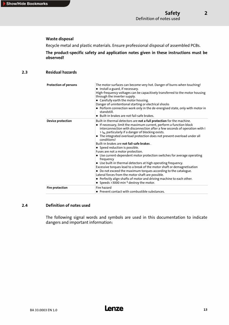
2.3 Residual hazards
Protection of persons Themotor surfaces can become very hot. Danger of burns when touching!Install a guard, if necessary.
High-frequency voltages can be capacitively transferred to the motor housingthrough the inverter supply.
Carefully earth the motor housing.Danger of unintentional starting or electrical shocks
Perform connection work only in the de-energised state, only with motor instandstill.Built-in brakes are not fail-safe brakes.
Device protection Built-in thermal detectors are not a full protection for the machine.If necessary, limit the maximum current, perform a function blockinterconnection with disconnection after a few seconds of operation with I> IN, particularly if a danger of blocking exists.The integrated overload protection does not prevent overload under allconditions!
Built-in brakes are not fail-safe brakes .Speed reduction is possible.
Fuses are not a motor protection.Use current-dependent motor protection switches for average operatingfrequencyUse built-in thermal detectors at high operating frequency.
Excessive torques lead to a break of the motor shaft or demagnetisationDo not exceed the maximum torques according to the catalogue.
Lateral forces from themotor shaft are possible.Perfectly align shafts of motor and drivingmachine to each other.Speeds >3000min-1 destroy the motor.
Fire protection Fire hazardPrevent contact with combustible substances.
2.4 Definition of notes used
The following signal words and symbols are used in this documentation to indicatedangers and important information:
SafetyDefinition of notes used
2
14 BA 33.0003 EN 1.0
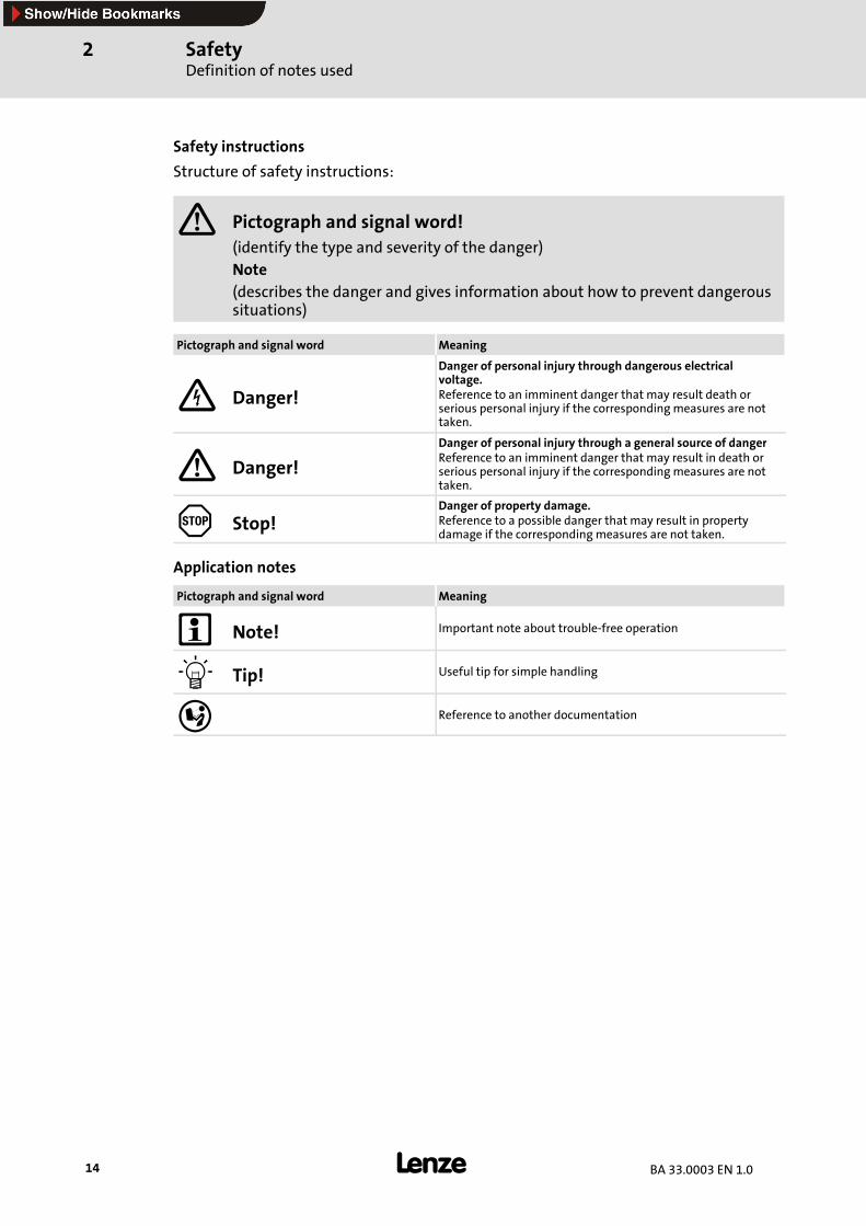
Safety instructions
Structure of safety instructions:
Pictograph and signal word!(identify the type and severity of the danger)Note(describes the danger and gives information about how to prevent dangeroussituations)
Pictograph and signal word Meaning
Danger!
Danger of personal injury through dangerous electricalvoltage.Reference to an imminent danger that may result death orserious personal injury if the correspondingmeasures are nottaken.
Danger!
Danger of personal injury through a general source of dangerReference to an imminent danger that may result in death orserious personal injury if the correspondingmeasures are nottaken.
Stop!Danger of property damage.Reference to a possible danger that may result in propertydamage if the correspondingmeasures are not taken.
Application notes
Pictograph and signal word Meaning
Note! Important note about trouble-free operation
Tip! Useful tip for simple handling
Reference to another documentation
Technical dataGeneral data/operating conditions
3
15BA 33.0003 EN 1.0
3 Technical data
3.1 General data/operating conditions
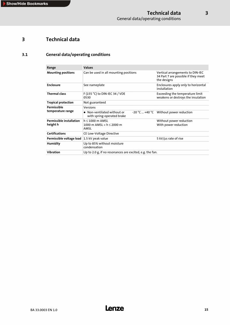
Range Values
Mounting positions Can be used in all mounting positions Vertical arrangements to DIN-IEC34 Part 7 are possible if they meetthe designs
Enclosure See nameplate Enclosures apply only to horizontalinstallation
Thermal class F (155 °C) to DIN-IEC 34 / VDE0530
Exceeding the temperature limitweakens or destroys the insulation
Tropical protection Not guaranteed
Permissible Versionstemperature range Non-ventilated without or
with spring-operated brake-20 °C ... +40 °C Without power reduction
Permissible installationheight h
h ≤ 1000 m AMSL1000 m AMSL < h ≤ 2000 mAMSL
Without power reductionWith power reduction
Certifications CE Low-Voltage Directive
Permissible voltage load 1.5 kV peak value 5 kV/µs rate of riseHumidity Up to 85% without moisture
condensation
Vibration Up to 2.0 g, if no resonances are excited, e.g. the fan.
Technical dataRated data
3
16 BA 33.0003 EN 1.0
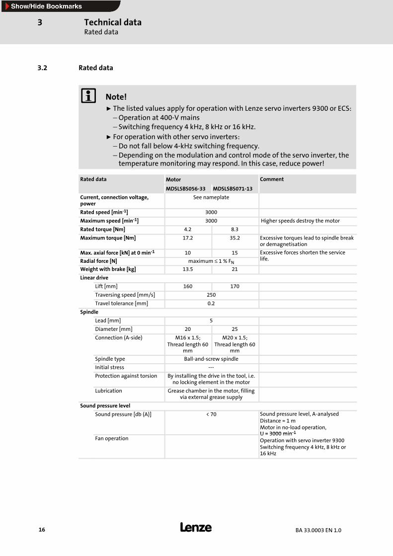
3.2 Rated data
Note!ƒ The listed values apply for operation with Lenze servo inverters 9300 or ECS:–Operation at 400-Vmains– Switching frequency 4 kHz, 8 kHz or 16 kHz.
ƒ For operation with other servo inverters:– Do not fall below 4-kHz switching frequency.– Depending on the modulation and control mode of the servo inverter, thetemperature monitoring may respond. In this case, reduce power!
Rated data Motor Comment
MDSLSBS056-33 MDSLSBS071-13
Current, connection voltage,power
See nameplate
Rated speed [min-1] 3000
Maximum speed [min-1] 3000 Higher speeds destroy the motor
Rated torque [Nm] 4.2 8.3
Maximum torque [Nm] 17.2 35.2 Excessive torques lead to spindle breakor demagnetisation
Max. axial force [kN] at 0 min-1 10 15 Excessive forces shorten the servicel fRadial force [N] maximum ≤ 1 % FNlife.
Weight with brake [kg] 13.5 21
Linear drive
Lift [mm] 160 170
Traversing speed [mm/s] 250
Travel tolerance [mm] 0.2
Spindle
Lead [mm] 5
Diameter [mm] 20 25
Connection (A-side) M16 x 1.5;Thread length 60
mm
M20 x 1.5;Thread length 60
mm
Spindle type Ball-and-screw spindle
Initial stress ---
Protection against torsion By installing the drive in the tool, i.e.no locking element in the motor
Lubrication Grease chamber in the motor, fillingvia external grease supply
Sound pressure level
Sound pressure [db (A)] < 70 Sound pressure level, A-analysedDistance = 1 mMotor in no-load operation,U = 3000 min-1
Fan operationU = 3000 min-1
Operation with servo inverter 9300Switching frequency 4 kHz, 8 kHz or16 kHz
Technical dataRated data
Holding brake (option)
3
17BA 33.0003 EN 1.0
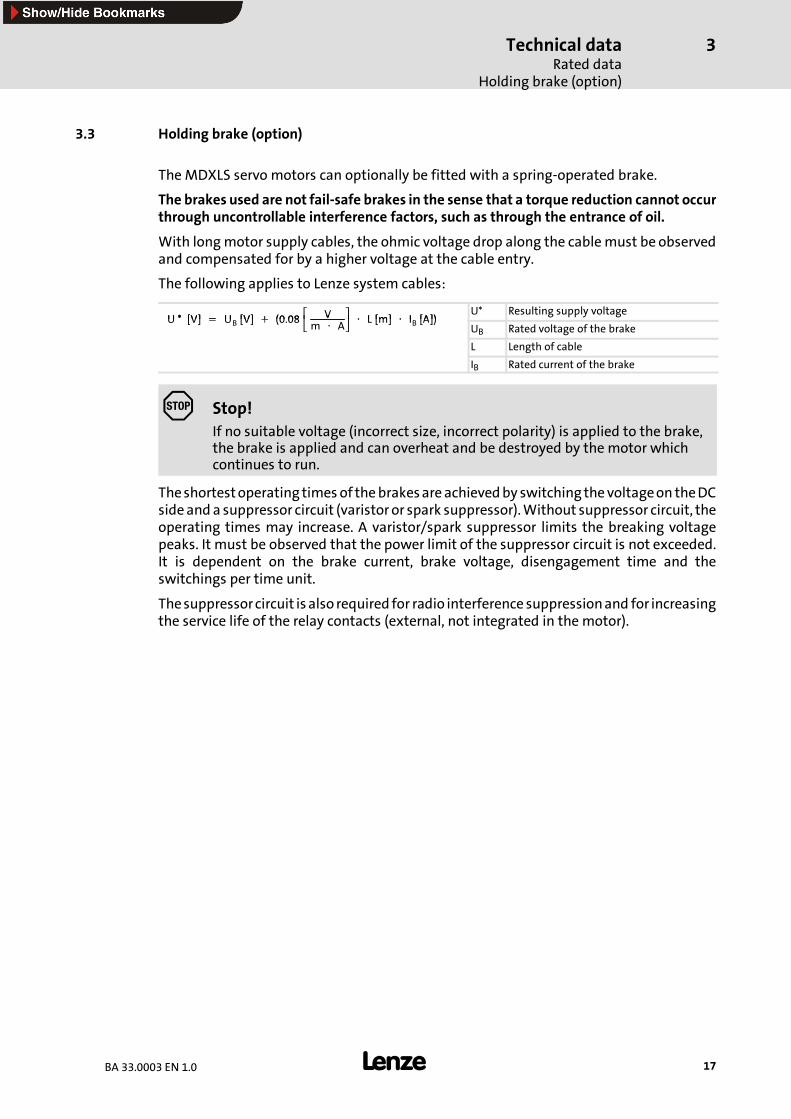
3.3 Holding brake (option)
TheMDXLS servo motors can optionally be fitted with a spring-operated brake.
The brakes used are not fail-safe brakes in the sense that a torque reduction cannot occurthrough uncontrollable interference factors, such as through the entrance of oil.
With longmotor supply cables, the ohmic voltage drop along the cablemust be observedand compensated for by a higher voltage at the cable entry.
The following applies to Lenze system cables:
U * [V] = U [V] + (0 08 V ⋅ L [m] ⋅ I [A])U* Resulting supply voltage
U * [V] = UB [V] + (0.08 Vm ⋅ A ⋅ L [m] ⋅ IB [A])
UB Rated voltage of the brake
L Length of cable
IB Rated current of the brake
Stop!If no suitable voltage (incorrect size, incorrect polarity) is applied to the brake,the brake is applied and can overheat and be destroyed by the motor whichcontinues to run.
Theshortestoperating times of thebrakesareachievedby switching thevoltageon theDCsideand a suppressor circuit (varistor or spark suppressor).Without suppressor circuit, theoperating times may increase. A varistor/spark suppressor limits the breaking voltagepeaks. It must be observed that the power limit of the suppressor circuit is not exceeded.It is dependent on the brake current, brake voltage, disengagement time and theswitchings per time unit.
Thesuppressorcircuit is also required for radio interference suppressionand for increasingthe service life of the relay contacts (external, not integrated in the motor).
Technical dataRated dataSpring-operated brakes
3
18 BA 33.0003 EN 1.0
3.3.1 Spring-operated brakes
The spring-operated brakes canbeused asholding and/or servicebrakes. Ifused as servicebrake, the permissible friction energy must not be exceeded; otherwise it would destroythe brake. Permissible operating speeds and ratings Spring-operated brakes catalogue.Emergency stops fromahigher speed arepossible, butwear increaseswith high switchingenergy.
Stop!In any case, the friction surfaces must be kept free of lubricant and grease,since even small amounts can drastically reduce the braking torque.
The use as a pure holding brake results in only minor wear at the friction surfaces.Emergency stops or the use as service brake creates wear at the friction surfaces, and theabrasion of the wear parts creates dust. The Lenze spring-operated brake BFK 458 can beadjusted up to 5 times, while the BFK 418, 457 and 460 cannot be adjusted (for detailscataloguesandoperating instructionsof spring-operatedbrakes).Brakes,whichcannotbeadjusted, must be replaced after reaching the wear limit.
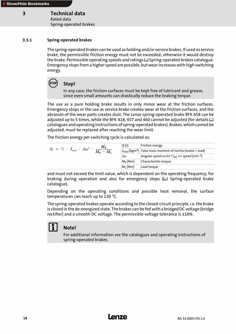
The friction energy per switching cycle is calculated as:
Q ½ J ∆ 2 MK Q [J] Friction energyQ = ½ ⋅ Jtotal ⋅ ∆ω2 ⋅
MKMK−ML Jtotal [kgm2] Total mass moment of inertia (motor + load)MK ML
∆ω Angular speed ω=2π n/60, n= speed [min-1]
MK [Nm] Characteristic torque
ML [Nm] Load torque
and must not exceed the limit value, which is dependent on the operating frequency, forbraking during operation and also for emergency stops ( Spring-operated brakecatalogue).
Depending on the operating conditions and possible heat removal, the surfacetemperatures can reach up to 130 °C.
The spring-operated brakes operate according to the closed-circuit principle, i.e. thebrakeis closed in thede-energized state. Thebrakes canbe fedwithabridgedDCvoltage (bridgerectifier) and a smooth DC voltage. The permissible voltage tolerance is ±10%.
Note!For additional information see the catalogues and operating instructions ofspring-operated brakes.
Mechancal installationAssembly of built-on accessories
4
19BA 33.0003 EN 1.0
4 Mechanical installation
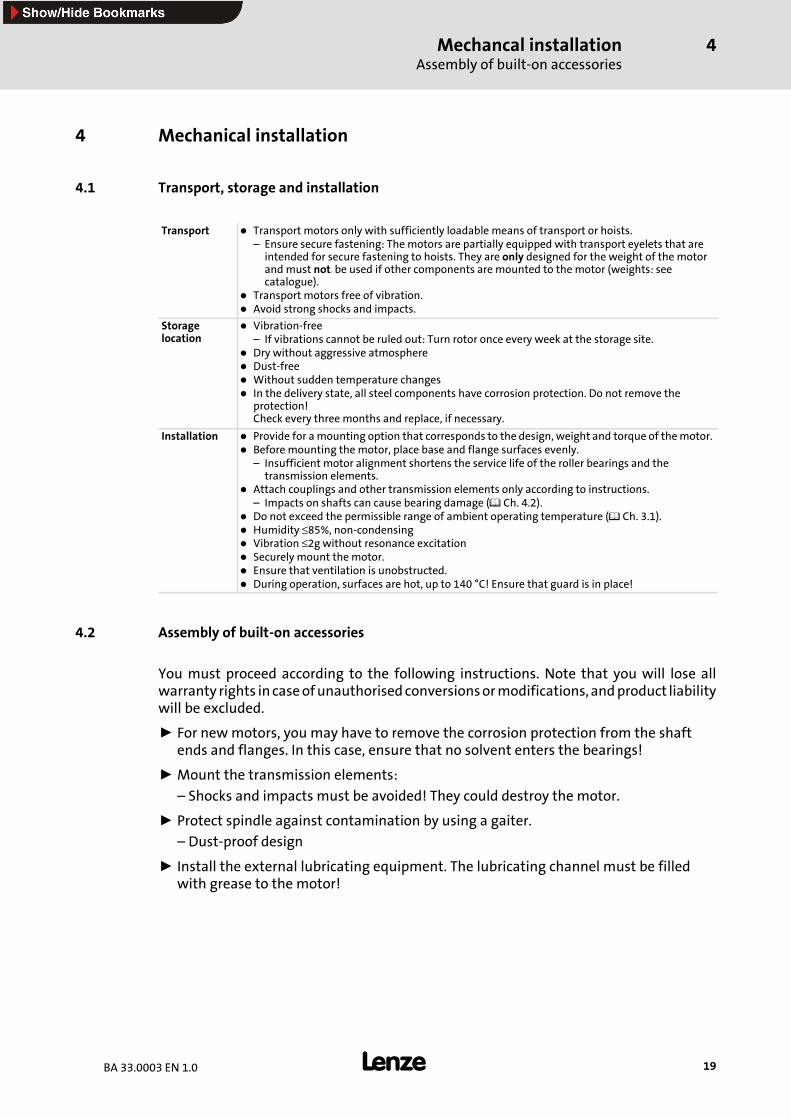
4.1 Transport, storage and installation
Transport Transport motors only with sufficiently loadable means of transport or hoists.– Ensure secure fastening: The motors are partially equipped with transport eyelets that areintended for secure fastening to hoists. They are only designed for the weight of the motorand must notn be used if other components are mounted to the motor (weights: seecatalogue).
Transport motors free of vibration.Avoid strong shocks and impacts.
Storagelocation
Vibration-free– If vibrations cannot be ruled out: Turn rotor once every week at the storage site.Dry without aggressive atmosphereDust-freeWithout sudden temperature changesIn the delivery state, all steel components have corrosion protection. Do not remove theprotection!Check every three months and replace, if necessary.
Installation Provide for amounting option that corresponds to the design, weight and torque of themotor.Before mounting the motor, place base and flange surfaces evenly.– Insufficient motor alignment shortens the service life of the roller bearings and thetransmission elements.
Attach couplings and other transmission elements only according to instructions.– Impacts on shafts can cause bearing damage ( Ch. 4.2).Do not exceed the permissible range of ambient operating temperature ( Ch. 3.1).Humidity ≤85%, non-condensingVibration ≤2g without resonance excitationSecurely mount the motor.Ensure that ventilation is unobstructed.During operation, surfaces are hot, up to 140 °C! Ensure that guard is in place!
4.2 Assembly of built-on accessories
You must proceed according to the following instructions. Note that you will lose allwarranty rights incaseofunauthorisedconversionsormodifications, andproduct liabilitywill be excluded.
ƒ For newmotors, you may have to remove the corrosion protection from the shaftends and flanges. In this case, ensure that no solvent enters the bearings!
ƒ Mount the transmission elements:
– Shocks and impacts must be avoided! They could destroy the motor.
ƒ Protect spindle against contamination by using a gaiter.
– Dust-proof design
ƒ Install the external lubricating equipment. The lubricating channel must be filledwith grease to the motor!
Mechancal installationConnection of external lubricant unit
4
20 BA 33.0003 EN 1.0
4.3 Connection of external lubricant unit
A
C
B
MDXLSBS056-002/1.0/C
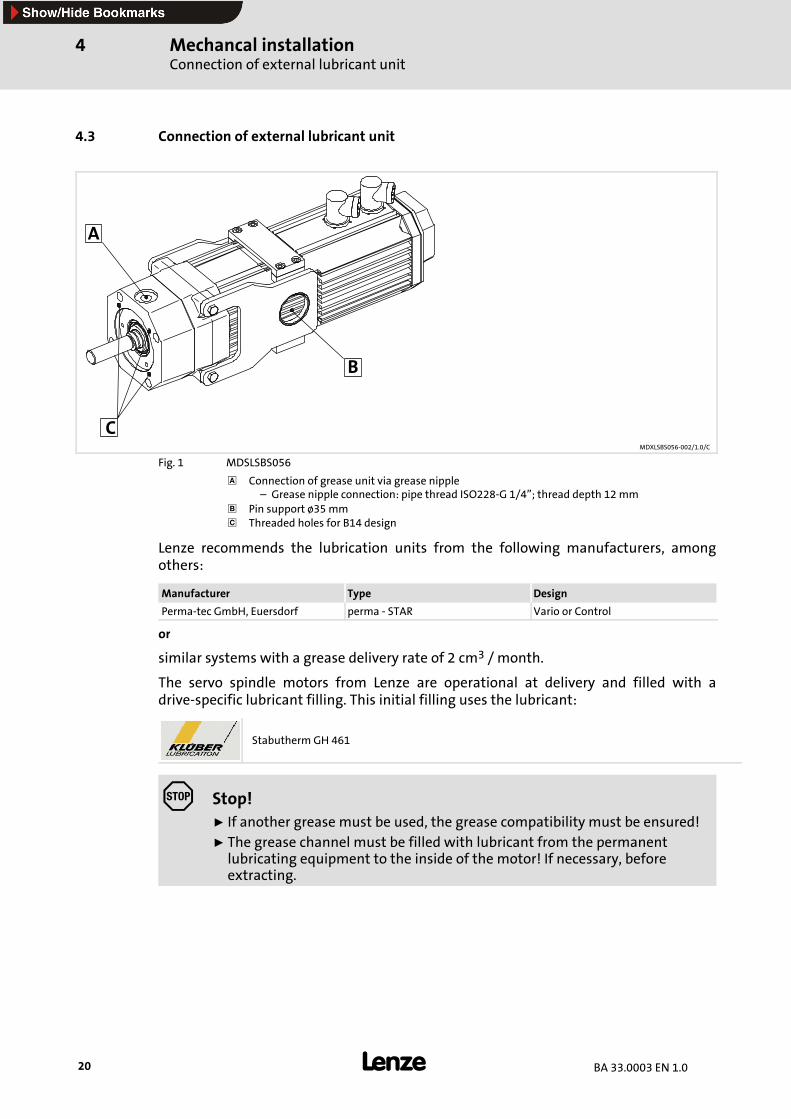
Fig. 1 MDSLSBS056
Connection of grease unit via grease nipple– Grease nipple connection: pipe thread ISO228-G 1/4”; thread depth 12mm
Pin support ø35mmThreaded holes for B14 design
Lenze recommends the lubrication units from the following manufacturers, amongothers:
Manufacturer Type Design
Perma-tec GmbH, Euersdorf perma - STAR Vario or Control
or
similar systems with a grease delivery rate of 2 cm3 / month.
The servo spindle motors from Lenze are operational at delivery and filled with adrive-specific lubricant filling. This initial filling uses the lubricant:
Stabutherm GH 461
Stop!ƒ If another grease must be used, the grease compatibility must be ensured!ƒ The grease channel must be filled with lubricant from the permanentlubricating equipment to the inside of the motor! If necessary, beforeextracting.
Mechancal installationBellows
4
21BA 33.0003 EN 1.0
Note!Please note that the recommendation of a lubricant/grease does not meanthat Lenze is liable for these lubricants or damages resulting fromincompatibilities of materials used.
4.4 Motor support
See Ch. 4.3
Stop!When installing the motor using the intended support, ensure that the boltbeing inserted in the support is completely seated.
ƒ MDSLS056: Bolt ∅35mmDepth of seat 6 mm
ƒ MDSLS071: Bolt ∅35mmDepth of seat 8 mm
Alternatively, themotors can bemounted using the fixing holes in the A-end shield in thetool/system (B14 mounting).
ƒ MDSLS056: Pitch circle ∅80 mm;M6
ƒ MDSLS071: Pitch circle ∅130 mm;M8
4.5 Bellows
To protect the spindle from dirt, it must be covered with dust-proof bellows.
Note!The bellows selection must consider the maximum occurring surfacetemperature of the motor!
Electrical installationImportant notes
5
22 BA 33.0003 EN 1.0
5 Electrical installation
5.1 Important notes
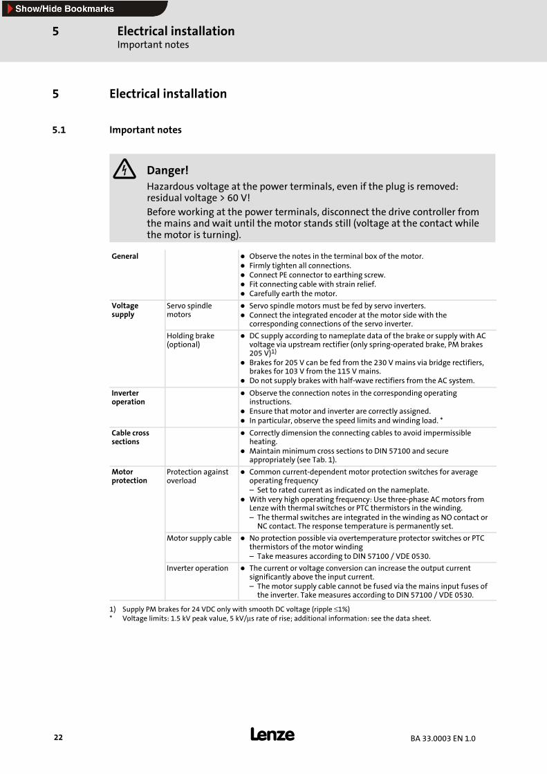
Danger!Hazardous voltage at the power terminals, even if the plug is removed:residual voltage > 60 V!
Before working at the power terminals, disconnect the drive controller fromthe mains and wait until the motor stands still (voltage at the contact whilethe motor is turning).
General Observe the notes in the terminal box of the motor.Firmly tighten all connections.Connect PE connector to earthing screw.Fit connecting cable with strain relief.Carefully earth the motor.
Voltagesupply
Servo spindlemotors
Servo spindle motors must be fed by servo inverters.Connect the integrated encoder at the motor side with thecorresponding connections of the servo inverter.
Holding brake(optional)
DC supply according to nameplate data of the brake or supply with ACvoltage via upstream rectifier (only spring-operated brake, PM brakes205 V)1)
Brakes for 205 V can be fed from the 230 Vmains via bridge rectifiers,brakes for 103 V from the 115 Vmains.Do not supply brakes with half-wave rectifiers from the AC system.
Inverteroperation
Observe the connection notes in the corresponding operatinginstructions.Ensure that motor and inverter are correctly assigned.In particular, observe the speed limits and winding load. *
Cable crosssections
Correctly dimension the connecting cables to avoid impermissibleheating.Maintain minimum cross sections to DIN 57100 and secureappropriately (see Tab. 1).
Motorprotection
Protection againstoverload
Common current-dependent motor protection switches for averageoperating frequency– Set to rated current as indicated on the nameplate.With very high operating frequency: Use three-phase ACmotors fromLenze with thermal switches or PTC thermistors in the winding.– The thermal switches are integrated in the winding as NO contact orNC contact. The response temperature is permanently set.
Motor supply cable No protection possible via overtemperature protector switches or PTCthermistors of the motor winding– Take measures according to DIN 57100 / VDE 0530.
Inverter operation The current or voltage conversion can increase the output currentsignificantly above the input current.– The motor supply cable cannot be fused via the mains input fuses ofthe inverter. Take measures according to DIN 57100 / VDE 0530.
1) Supply PM brakes for 24 VDC only with smooth DC voltage (ripple ≤1%)* Voltage limits: 1.5 kV peak value, 5 kV/µs rate of rise; additional information: see the data sheet.
Electrical installationImportant notes
5
23BA 33.0003 EN 1.0
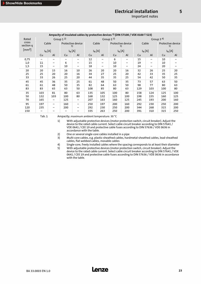
Ampacity of insulated cables by protective devices 1) (DIN 57100 / VDE 0100 T 523)
Rated Group 1 2) Group 2 3) Group 3 4)
crosssection q
[ 2]
Cable Protective device5)
Cable Protective device5)
Cable Protective device5)
[mm2] IN [A] IN [A] IN [A] IN [A] IN [A] IN [A]
Cu Al Cu Al Cu Al Cu Al Cu Al Cu Al
0,751,01,5
–1115
–––
–610
–––
121518
–––
61010
–––
151924
–––
101020
–––
202533
202533
152026
162025
101620
263444
202735
202535
162025
324254
263342
253550
202535
456183
456183
364865
355063
253550
6182108
486485
506380
355063
7398129
5777103
6380100
506380
355070
103132165
81103–
80100125
6380–
135168207
105132163
100125160
80100125
158198245
124155193
125160200
100125160
95120150
197235–
–––
160200–
–––
250292335
197230263
200250250
160200200
292344391
230268310
250315315
200200250
Tab. 1 Ampacity; maximum ambient temperature: 30 °C
1) With adjustable protective devices (motor protection switch, circuit breaker). Adjust thedevice to the rated cable current. Select cable circuit breaker according to DIN 57641 /VDE 0641 / CEE 19 and protective cable fuses according to DIN 57636 / VDE 0636 inaccordance with the table.
2) One or several single-core cables installed in a pipe3) Multi-core cables, e.g. plastic-sheathed cables, hardmetal-sheathed cables, lead-sheathed
cables, flat webbed cables, movable cables4) Single-core, freely installed cables where the spacing corresponds to at least their diameter5) With adjustable protective devices (motor protection switch, circuit breaker). Adjust the
device to the rated cable current. Select cable circuit breaker according to DIN 57641 / VDE0641 / CEE 19 and protective cable fuses according to DIN 57636 / VDE 0636 in accordancewith the table.
Electrical installationImportant notesWiring diagrams for servo spindle motors MDSLS
5
24 BA 33.0003 EN 1.0
5.1.1 EMC-compliant wiring
TheEMC-compliantwiringofthemotors isdescribed indetail in theoperating instructionsof the Lenze servo inverters 9300 and ECS.
ƒ Use of EMC threaded joints made out of metal with shield connection.
ƒ Shield connection at the motor and at the device.
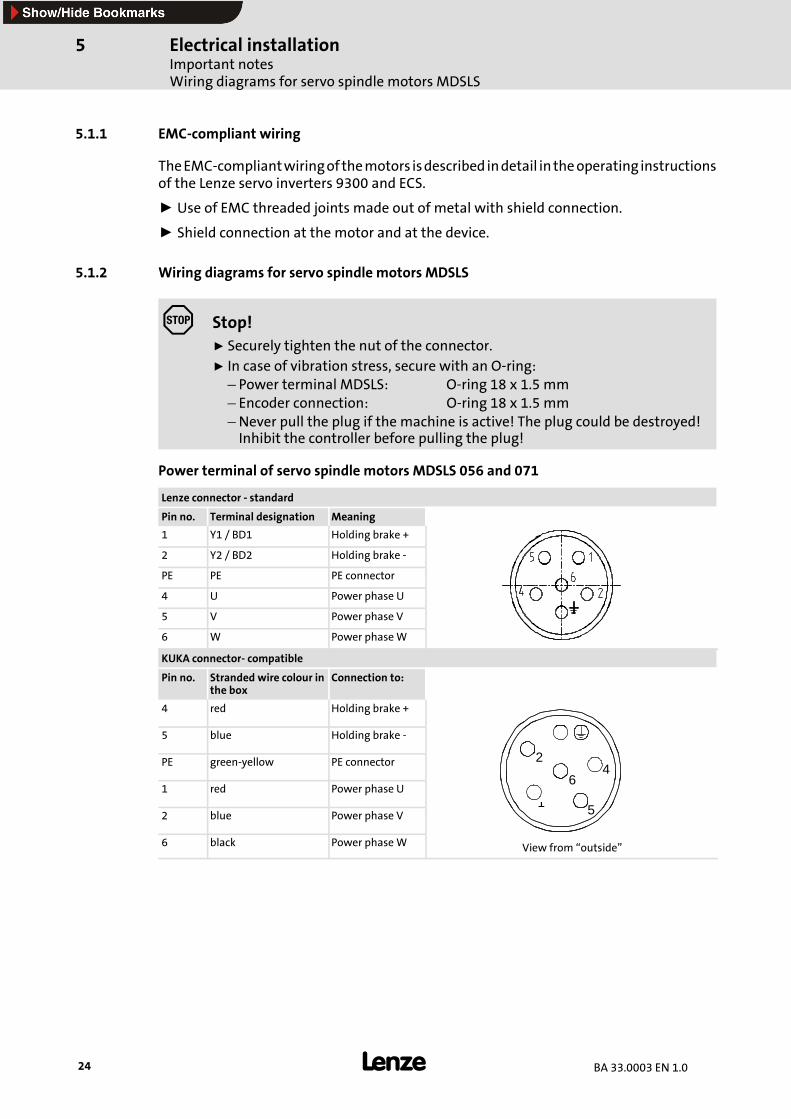
5.1.2 Wiring diagrams for servo spindle motors MDSLS
Stop!ƒ Securely tighten the nut of the connector.ƒ In case of vibration stress, secure with an O-ring:– Power terminal MDSLS: O-ring 18 x 1.5 mm– Encoder connection: O-ring 18 x 1.5 mm–Never pull the plug if the machine is active! The plug could be destroyed!Inhibit the controller before pulling the plug!
Power terminal of servo spindle motors MDSLS 056 and 071
Lenze connector - standard
Pin no. Terminal designation Meaning
1 Y1 / BD1 Holding brake +
2 Y2 / BD2 Holding brake -
PE PE PE connector
4 U Power phase U
5 V Power phase V
6 W Power phaseW
KUKA connector- compatible
Pin no. Stranded wire colour inthe box
Connection to:
4 red Holding brake +
5 blue Holding brake -
PE green-yellow PE connector 24
1 red Power phase U6
2 blue Power phase V1 5
6 black Power phaseW View from “outside”
Electrical installationImportant notes
Wiring diagrams for servo spindle motors MDSLS
5
25BA 33.0003 EN 1.0
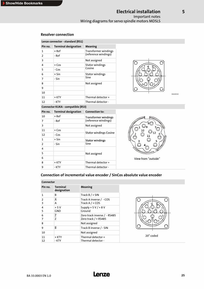
Resolver connection
Lenze connector - standard (RS1)
Pin no. Terminal designation Meaning
1 + Ref Transformer windings( f i di )2 - Ref
g(reference windings)
3 Not assigned
4 + Cos Stator windingsC i5 - Cos
gCosine
6 + Sin Stator windingsSi7 - Sin
gSine
8 Not assigned
9
g
10hPPKMMNULP
11 + KTY Thermal detector +hPPKMMNULP
12 - KTY Thermal detector -
Connector KUKA - compatible (RS3)
Pin no. Terminal designation Connection to:
10 + Ref Transformer windings7 - Ref
Transformer windings(reference windings)
83 Not assigned
1 78
911 + Cos
Stator windings Cosine
1 7910
1212 - Cos
Stator windings Cosine 2 610
1112
1 + Sin Stator windings 3 5
11
2 - SinStator windingsSine
344
5
444
5 Not assigned
6
Not assigned
View from “outside”8 + KTY Thermal detector +
View from outside
9 - KTY Thermal detector -
Connection of incremental value encoder / SinCos absolute value encoder
Connector
Pin no. Terminaldesignation
Meaning
1 B Track B / + SIN
23
AA
Track A inverse / - COSTrack A / + COS
45
+ 5 VGND
Supply + 5 V / + 8 VGround
67
ZZ
Zero track inverse / - RS485Zero track / + RS485
8 Not assigned
9 B Track B inverse / - SIN
10 Not assigned° d d11
12+ KTY- KTY
Thermal detector +Thermal detector -
20° coded
Commissioning6
26 BA 33.0003 EN 1.0
6 Commissioning
Stop!The integrated thermal sensor does not prevent overload under all conditions!
At commissioning, reduce the maximum current, e.g. to the rated current ofthe motor!Perform function block interconnection (servo inverter 9300) or I2xtmonitoring (servo inverter ECS) with disconnection after several seconds ofoperation with I>IN, particularly in case of danger of blocking.
ƒ Commission the drive system according to the operating instructions of the drivecontroller.
– Entering motor data, parameter setting via Global Drive Control
– Parameter setting of motor temperature detection (is carried out automaticallywith parameter setting via GDC)
– Specifying feedback system for speed and position control
– Selecting the operating mode (control structure)
– Entering machine data
– Optimising the drive behaviour, if necessary (optimisation of current, speed, fieldand field-weakening control; observe the notes below!).
Stop!The parameter data that are set via GDC are used as default setting and mustbe optimised specific to each application!
Servo controller 9300
The input variable of the current controller is normalised to themaximum device currentImax. device. This allows the maximum device current to directly influence the currentcontroller gain Vp. If a smaller or larger device is used after the current controlleradjustment, the current controller must be adjusted again or the Vp must be matched.
The input and output variables of the speed controller are normalised to the maximumcurrent Imax. (C0022)and themaximumspeednmax. (C0011).This allowsC0022andC0011to directly influence the gain of the speed controller Vpn.
ƒ The following applies to the servo controller 9300:
– Vp proportional Imax. device
– Vpn proportional nmax. (C0011)
– Vpn proportional 1/Imax. (C0022)
Commissioning 6
27BA 33.0003 EN 1.0
Servo controller ECS
The input and output variables of the speed controller are normalised to the maximumcurrent Imax. (C0022) and themaximumspeednmax (C0011). This allowsC0022andC0011to directly influence the gain of the speed controller Vpn.
ƒ The following applies to the servo controller ECS:
– Vpn proportional nmax. (C0011)
– Vpn proportional 1/Imax. (C0022)
Parameter setting of motor temperature detection
Stop!
ƒ The integrated overload protection does not prevent overload underall conditions!
ƒ Reduce maximum current to required value!
The motor winding temperature is monitored by thermal detectors.
Function block interconnection
Stop!Perform function block interconnection (servo inverter 9300) or I2xtmonitoring (servo inverter ECS) with disconnection after several seconds ofoperation with I > IN, particularly in case of danger of blocking.
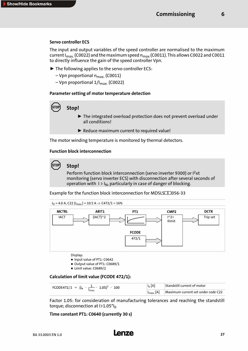
Example for the function block interconnection for MDSLS 056-33
IO = 4.0 A, C22 (Imax.) = 10.5 A⇒ C472/1 = 16%
IACT (IACT)^2 I^2>Ilimit
472/1
Trip set
Display:Input value of PT1: C0642Output value of PT1: C0689/1Limit value: C0689/2
Calculation of limit value (FCODE 472/1):
FCODE472∕1 = (Io ⋅ 1I
⋅ 1.05)2 ⋅ 100 Io [A] Standstill current of motorFCODE472∕1 = (Io Imax.1.05) 100
Imax. [A] Maximum current set under code C22
Factor 1.05: for consideration of manufacturing tolerances and reaching the standstilltorque; disconnection at I>1.05*I0
Time constant PT1: C0640 (currently 30 s)
Commissioning6
28 BA 33.0003 EN 1.0
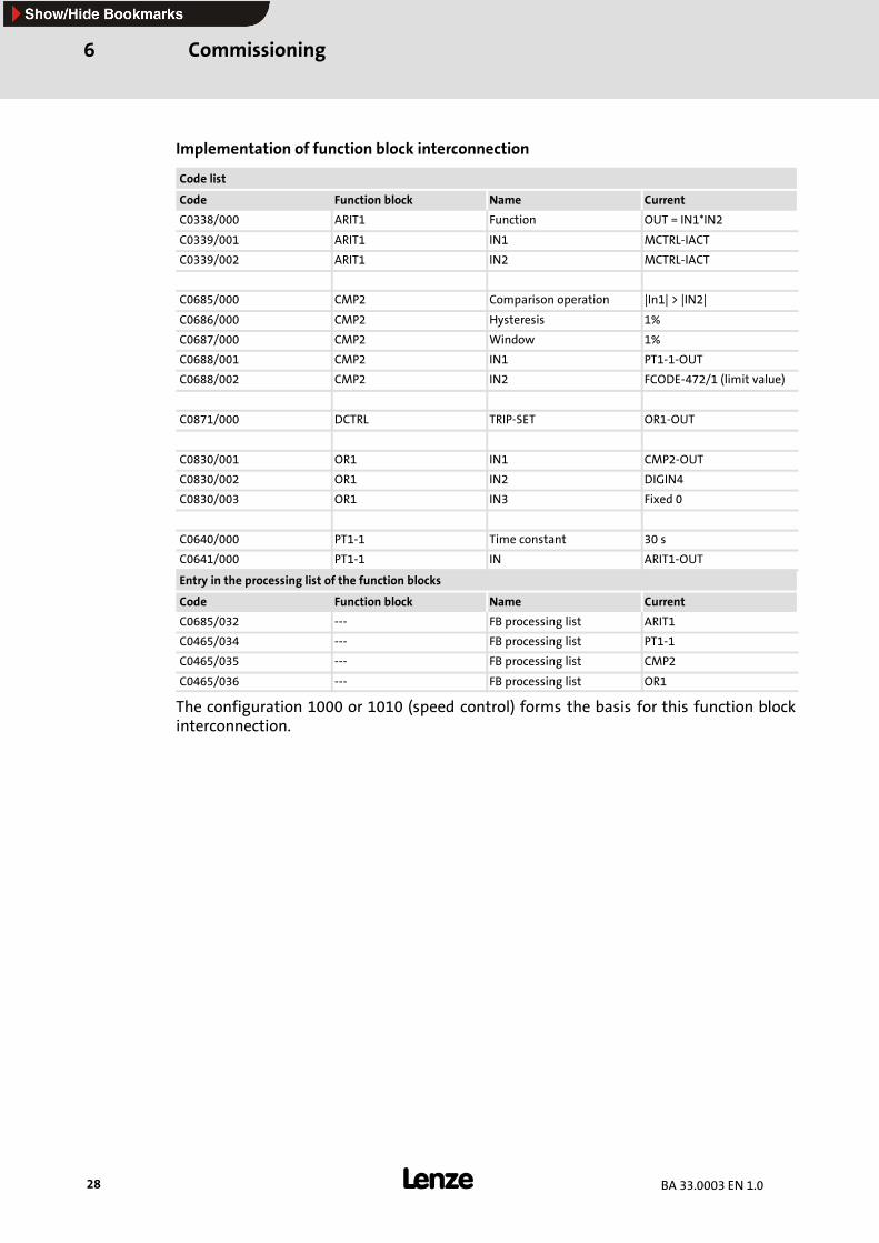
Implementation of function block interconnection
Code list
Code Function block Name Current
C0338/000 ARIT1 Function OUT = IN1*IN2
C0339/001 ARIT1 IN1 MCTRL-IACT
C0339/002 ARIT1 IN2 MCTRL-IACT
C0685/000 CMP2 Comparison operation |In1| > |IN2|
C0686/000 CMP2 Hysteresis 1%
C0687/000 CMP2 Window 1%
C0688/001 CMP2 IN1 PT1-1-OUT
C0688/002 CMP2 IN2 FCODE-472/1 (limit value)
C0871/000 DCTRL TRIP-SET OR1-OUT
C0830/001 OR1 IN1 CMP2-OUT
C0830/002 OR1 IN2 DIGIN4
C0830/003 OR1 IN3 Fixed 0
C0640/000 PT1-1 Time constant 30 s
C0641/000 PT1-1 IN ARIT1-OUT
Entry in the processing list of the function blocks
Code Function block Name Current
C0685/032 --- FB processing list ARIT1
C0465/034 --- FB processing list PT1-1
C0465/035 --- FB processing list CMP2
C0465/036 --- FB processing list OR1
The configuration 1000 or 1010 (speed control) forms the basis for this function blockinterconnection.
CommissioningFunctional test
6
29BA 33.0003 EN 1.0
6.1 Before switching on
Before the initial commissioning, before commissioning after an extended standstill timeor before commissioning after an overhaul of the motor, absolutely check the following:
ƒ Are all screwed connections of the mechanical and electrical parts firmly tightened?
ƒ Is the unrestricted cooling-air inlet and outlet ensured?
ƒ Are the protective devices against overheating (thermal sensor evaluation) effective?
ƒ Is the drive controller correctly parameterised for the motor?( Drive controller operating instructions)
ƒ Are the electrical connections o.k.?
ƒ Does the motor connection have the correct phase sequence?
ƒ Are rotating parts and surfaces, which can become very hot, protected againsttouching?
ƒ Is the permanent lubrication connected?
Danger!Built-in brakes are not fail-safe brakes!
6.2 Functional test
ƒ After commissioning, check all single functions of the drive:
– Direction of rotation of the motorIf the motor does not turn in the correct direction, exchange two phases.
– Torque behaviour and current capacity
– Braking effect of the mounted brake
– Function of the feedback system
ƒ In case of malfunctions or faults: Ch. 8.
CommissioningMotor connectionConnection of SinCos encoder
6
30 BA 33.0003 EN 1.0
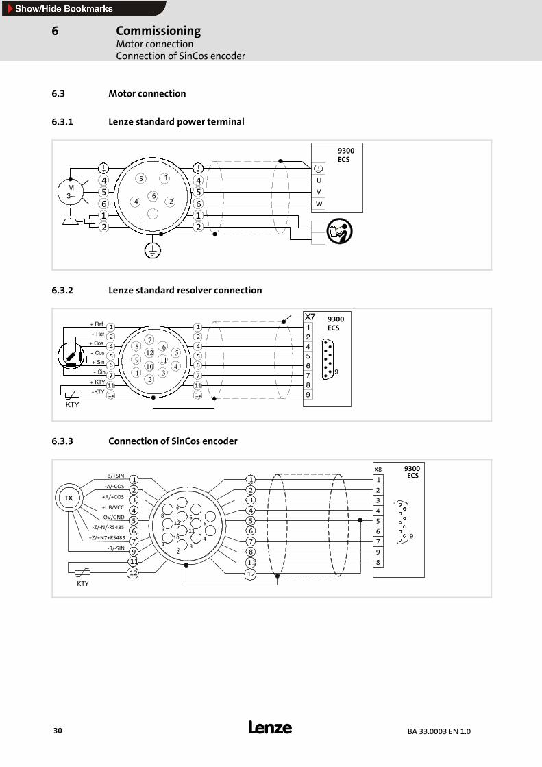
6.3 Motor connection
6.3.1 Lenze standard power terminal
5
46
2
1
12
456
12
456
U
V
W
M3~
9300ECS
6.3.2 Lenze standard resolver connection
KTY
+ Cos
+ Sin
+ KTY
--KTY
-- Sin
-- Cos
-- Ref
+ RefX7
21 3
4
56
78
910
12
12
56789
41
9
1
2
4
56
77
11
12
1
2
4
56
7
11
12
11
9300ECS
6.3.3 Connection of SinCos encoder
KTY
+A/+COS
-Z/-N/-RS485
-B/-SIN
+UB/VCC
-A/-COS
+B/+SIN
2
1 34
56
78
9
10
12
32
1
5
6
X8
1
2
5
6
7
8
9
4
3
4
8
7
32
1
5
6
7
4
911
12
TX
OV/GND
+Z/+N7+RS485
9300ECS
11
12
11
1
9
During operation 6
31BA 33.0003 EN 1.0
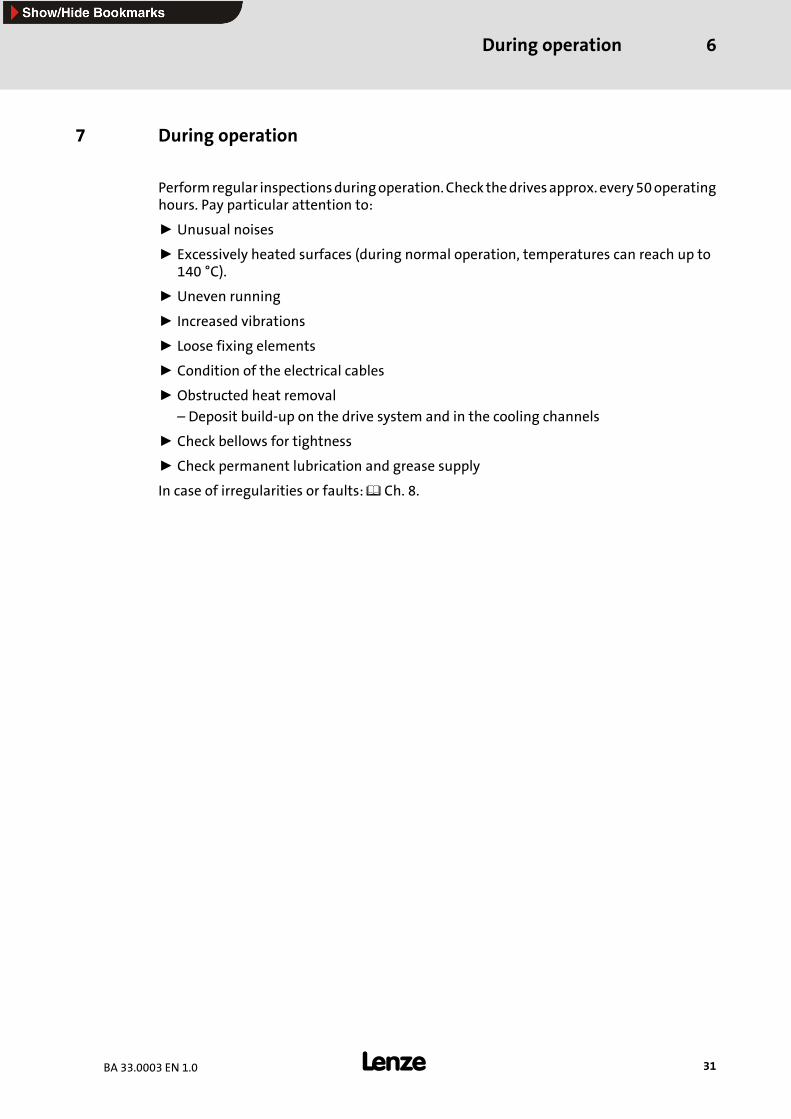
7 During operation
Performregular inspectionsduringoperation.Checkthedrivesapprox.every50operatinghours. Pay particular attention to:
ƒ Unusual noises
ƒ Excessively heated surfaces (during normal operation, temperatures can reach up to140 °C).
ƒ Uneven running
ƒ Increased vibrations
ƒ Loose fixing elements
ƒ Condition of the electrical cables
ƒ Obstructed heat removal
– Deposit build-up on the drive system and in the cooling channels
ƒ Check bellows for tightness
ƒ Check permanent lubrication and grease supply
In case of irregularities or faults: Ch. 8.
Troubleshooting and fault elimination8
32 BA 33.0003 EN 1.0
8 Troubleshooting and fault elimination
If faults occur during the operation of the drive system:
ƒ First check the possible causes of malfunction according to the following table.
ƒ Also observe the corresponding chapters in the operating instructions to the othercomponents of the drive system.
If the fault cannot be remedied using one of the listedmeasures, please contact the LenzeService.
Danger!ƒ Perform all work at the drive system only in the de-energised state!
ƒ Hot motor surfaces, up to 140 °C. Observe cooling times!
ƒ Remove the load from themotors or secure loads acting upon the drive!
Troubleshooting and fault elimination 8
33BA 33.0003 EN 1.0
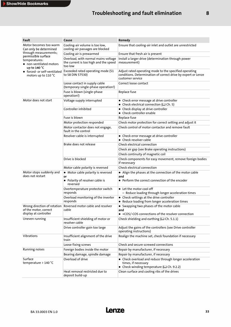
Fault Cause Remedy
Motor becomes too warmCan only be determined
Cooling-air volume is too low,cooling-air passages are blocked
Ensure that cooling-air inlet and outlet are unrestrictedCan only be determinedthrough measurements;permissible surface
Cooling air is prewarmed Ensure that fresh air is presentpermissible surfacetemperatures:
non-ventilated motorsup to 140 °C
Overload, with normal mains voltagethe current is too high and the speedtoo low
Install a larger drive (determination through powermeasurement)
up to 140 Cforced- or self-ventilatedmotors up to 110 °C
Exceeded rated operating mode (S1to S8 DIN 57530)
Adjust rated operating mode to the specified operatingconditions. Determination of correct drive by expert or Lenzecustomer service
Loose contact in supply cable(temporary single-phase operation!)
Correct loose contact
Fuse is blown (single-phaseoperation!)
Replace fuse
Motor does not start Voltage supply interrupted Check error message at drive controllerCheck electrical connection ( Ch. 5)
Controller inhibited Check display at drive controllerCheck controller enable
Fuse is blown Replace fuse
Motor protection responded Check motor protection for correct setting and adjust it
Motor contactor does not engage,fault in the control
Check control of motor contactor and remove fault
Resolver cable is interrupted Check error message at drive controllerCheck resolver cable
Brake does not release Check electrical connection
Check air gap (see Brake operating instructions)
Check continuity of magnetic coil
Drive is blocked Check components for easy movement, remove foreign bodiesif necessary
Motor cable polarity is reversed Check electrical connection
Motor stops suddenly anddoes not restart
Motor cable polarity is reversedor
Polarity of resolver cable isreversed
Align the phases at the connection of the motor cableand
Perform the correct connection of the encoder
Overtemperature protector switchresponds
Let the motor cool off– Reduce loading through longer acceleration times
Overload monitoring of the inverterresponds
Check settings at the drive controllerReduce loading from longer acceleration times
Wrong direction of rotationof the motor, correctdisplay at controller
Reversed motor cable and resolvercable
Swapping two phases of the motor cableand
+COS/-COS connections of the resolver connection
Uneven running Insufficient shielding of motor orresolver cable
Check shielding and earthing ( Ch. 5.1.1)
Drive controller gain too large Adjust the gains of the controllers (see Drive controlleroperating instructions)
Vibrations Insufficient alignment of the drivetrain
Realign the machine set, check foundation if necessary
Loose fixing screws Check and secure screwed connections
Running noises Foreign bodies inside the motor Repair by manufacturer, if necessaryg
Bearing damage, spindle damage Repair by manufacturer, if necessary
Surfacetemperature > 140 °C
Overload of drive Check overload and reduce through longer accelerationtimes, if necessaryCheck winding temperature ( Ch. 9.2.2)
Heat removal restricted due todeposit build-up
Clean surface and cooling ribs of the drives
Maintenance/RepairMaintenance operationsAdjustment of resolver for synchronous servo motors
9
34 BA 33.0003 EN 1.0
9 Maintenance/repair
9.1 Maintenance intervals
ƒ The motors are generally maintenance-free, except for the lubrication of the spindle.
ƒ Wear occurs only at bearings, spindles and seals.
– Check spindle, bearings for running noises (no later than approx. 15,000 h).
ƒ To avoid overheating, regularly remove the deposit build-up on the drives.
ƒ It is recommended to regularly perform an inspection after approx. 50 operatinghours. This allows for early identification and removal of irregularities or faults.
9.2 Maintenance operations
Stop!ƒ Ensure that no foreign bodies can enter the inside of the motor!ƒ Perform all work at the drive system only in the de-energised state!ƒ Separate drives from the electrical supply!
ƒ Hot motor surfaces, up to 140 °C. Observe cooling times!ƒ Remove the load from the motors or secure loads acting upon the drive!
ƒ Do not pull the plug if the machine is active!ƒ Check the bellows for correct seating!
9.2.1 Adjustment of resolver for synchronous servo motors
The resolver from Lenze is adjusted so that the faultless operation is ensured withoutadjustment at the drive controller.
If the resolver is twisted, e.g. through working on the motor, you must readjust it orperform a rotor adjustment at the drive controller.
ƒ For the rotor adjustment, the motor must turn without load at the drive controller(see the operating instructions of the drive controller). The rotor adjustment is storedat the drive controller and applies only to the respective combination of motor anddrive controller.
ƒ Resolver adjustment
1. Release brake, if necessary, clear motor shaft end.
2. Connect resolver to controller and determine the current rotor angle (see OperatingInstructions of Controller).
3. Allow DC current (< IN of motor) to flow from phase V (positive connection) to phaseW (negative connection), phase U is without current.
4. Turn resolver stator so that the controller shows rotor angle ”0”.
5. Secure the resolver stator in this position.
Maintenance/RepairMaintenance operations
Lubricant change
9
35BA 33.0003 EN 1.0
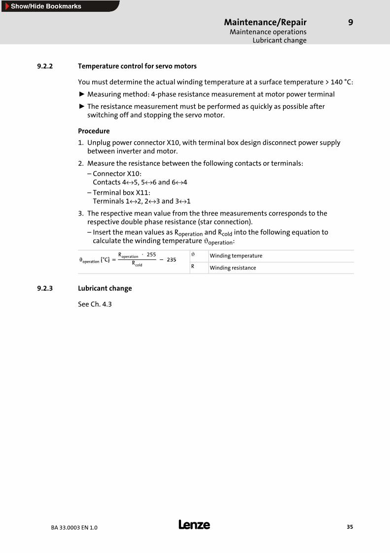
9.2.2 Temperature control for servo motors
You must determine the actual winding temperature at a surface temperature > 140 °C:
ƒ Measuring method: 4-phase resistance measurement at motor power terminal
ƒ The resistance measurement must be performed as quickly as possible afterswitching off and stopping the servo motor.
Procedure
1. Unplug power connector X10, with terminal box design disconnect power supplybetween inverter and motor.
2. Measure the resistance between the following contacts or terminals:
– Connector X10:Contacts 4↔5, 5↔6 and 6↔4
– Terminal box X11:Terminals 1↔2, 2↔3 and 3↔1
3. The respective mean value from the three measurements corresponds to therespective double phase resistance (star connection).
– Insert the mean values as Roperation and Rcold into the following equation tocalculate the winding temperature ϑoperation:
Âoperation [°C]=Roperation ⋅ 255
R− 235
ϑ Winding temperatureÂoperation [ C]= Rcold
− 235R Winding resistance
9.2.3 Lubricant change
See Ch. 4.3
Maintenance/RepairRepairClearing device
9
36 BA 33.0003 EN 1.0
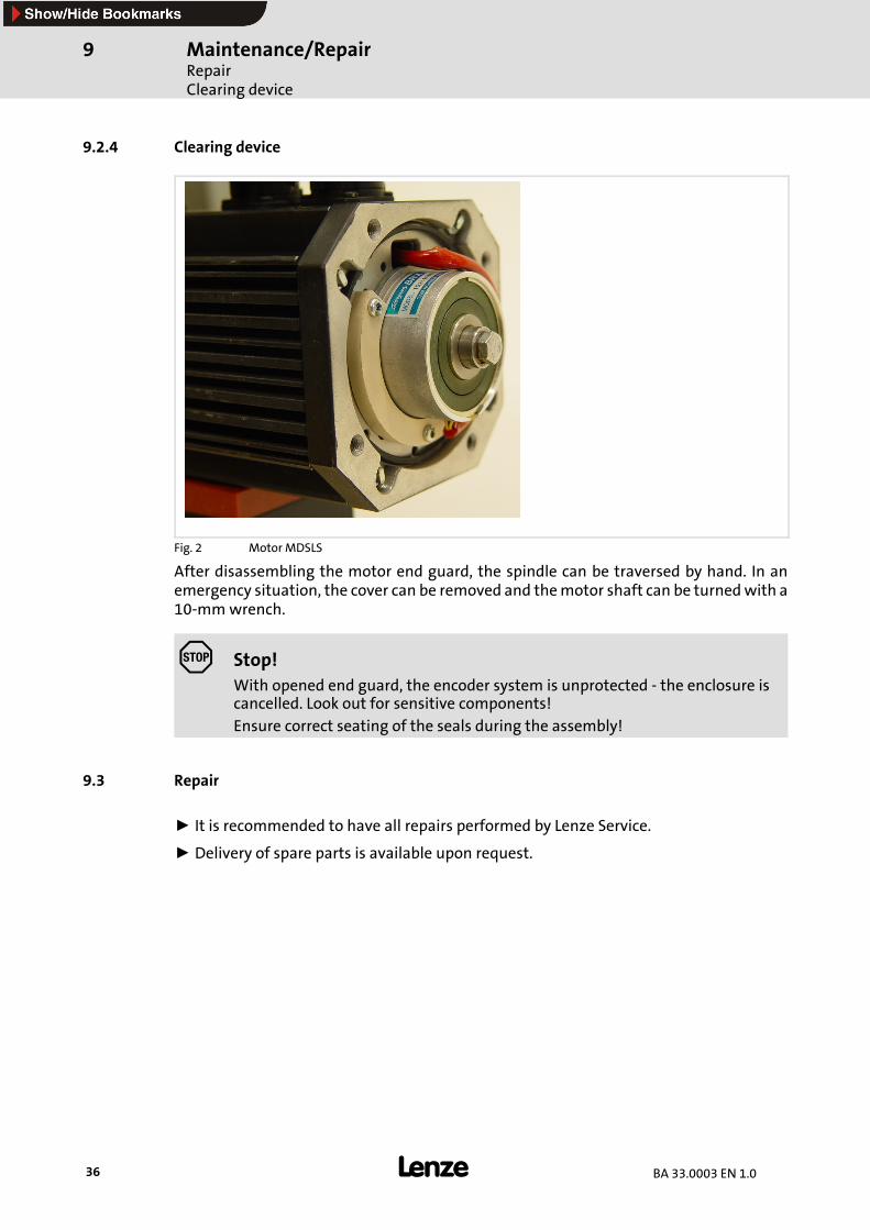
9.2.4 Clearing device
Fig. 2 Motor MDSLS
After disassembling the motor end guard, the spindle can be traversed by hand. In anemergency situation, the cover can be removed and themotor shaft can be turnedwith a10-mmwrench.
Stop!With opened end guard, the encoder system is unprotected - the enclosure iscancelled. Look out for sensitive components!
Ensure correct seating of the seals during the assembly!
9.3 Repair
ƒ It is recommended to have all repairs performed by Lenze Service.
ƒ Delivery of spare parts is available upon request.
AppendixManufacturer’s Certification
10
37BA 33.0003 EN 1.0
10 Appendix
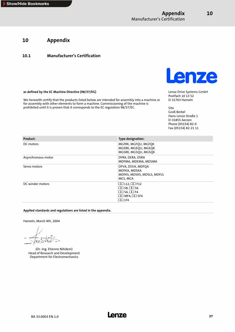
10.1 Manufacturer’s Certification
as defined by the EC Machine Directive (98/37/EG)
We herewith certify that the products listed below are intended for assembly into a machine orfor assembly with other elements to form a machine. Commissioning of the machine isprohibited until it is proven that it corresponds to the EC regulation 98/37/EC.
Lenze Drive Systems GmbHPostfach 10 13 52D-31763 Hameln
SiteGroß BerkelHans-Lenze Straße 1D-31855 AerzenPhone (05154) 82-0Fax (05154) 82-21 11
Product: Type designation:
DCmotors MGFRK, MGFQU, MGFQKMGERK, MGEQU, MGEQKMGSRK, MGSQU, MGSQK
Asynchronous motor DFRA, DERA, DSRAMDFMA, MDEMA, MDSMA
Servo motors DFVA, DSVA, MDFQAMDFKA, MDSKAMDFKS, MDSKS, MDSLS, MDFLSMCS, MCA
DC winder motors L12, F12S8, S6S4, F4MF4, SF4LF4
Applied standards and regulations are listed in the appendix.
Hameln, March 4th, 2004
(Dr.-Ing. Etienne Nitidem)Head of Research and DevelopmentDepartment for Electromechanics
AppendixManufacturer’s Certification
10
38 BA 33.0003 EN 1.0
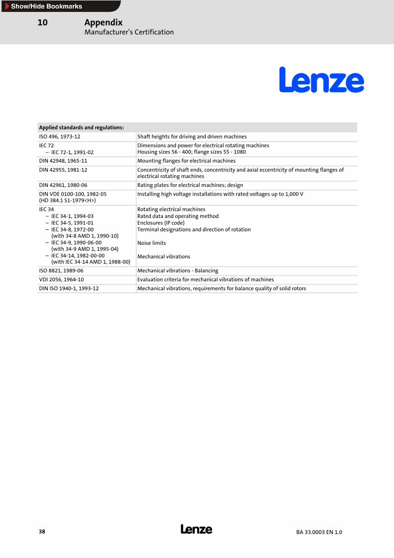
Applied standards and regulations:
ISO 496, 1973-12 Shaft heights for driving and driven machines
IEC 72– IEC 72-1, 1991-02
Dimensions and power for electrical rotating machinesHousing sizes 56 - 400; flange sizes 55 - 1080
DIN 42948, 1965-11 Mounting flanges for electrical machines
DIN 42955, 1981-12 Concentricity of shaft ends, concentricity and axial eccentricity of mounting flanges ofelectrical rotating machines
DIN 42961, 1980-06 Rating plates for electrical machines; design
DIN VDE 0100-100, 1982-05(HD 384.1 S1-1979<H>)
Installing high voltage installations with rated voltages up to 1,000 V
IEC 34– IEC 34-1, 1994-03– IEC 34-5, 1991-01– IEC 34-8, 1972-00(with 34-8 AMD 1, 1990-10)
– IEC 34-9, 1990-06-00(with 34-9 AMD 1, 1995-04)
– IEC 34-14, 1982-00-00(with IEC 34-14 AMD 1, 1988-00)
Rotating electrical machinesRated data and operating methodEnclosures (IP code)Terminal designations and direction of rotation
Noise limits
Mechanical vibrations
ISO 8821, 1989-06 Mechanical vibrations - Balancing
VDI 2056, 1964-10 Evaluation criteria for mechanical vibrations of machines
DIN ISO 1940-1, 1993-12 Mechanical vibrations, requirements for balance quality of solid rotors
AppendixEC Declaration of Conformity ’96
10
39BA 33.0003 EN 1.0
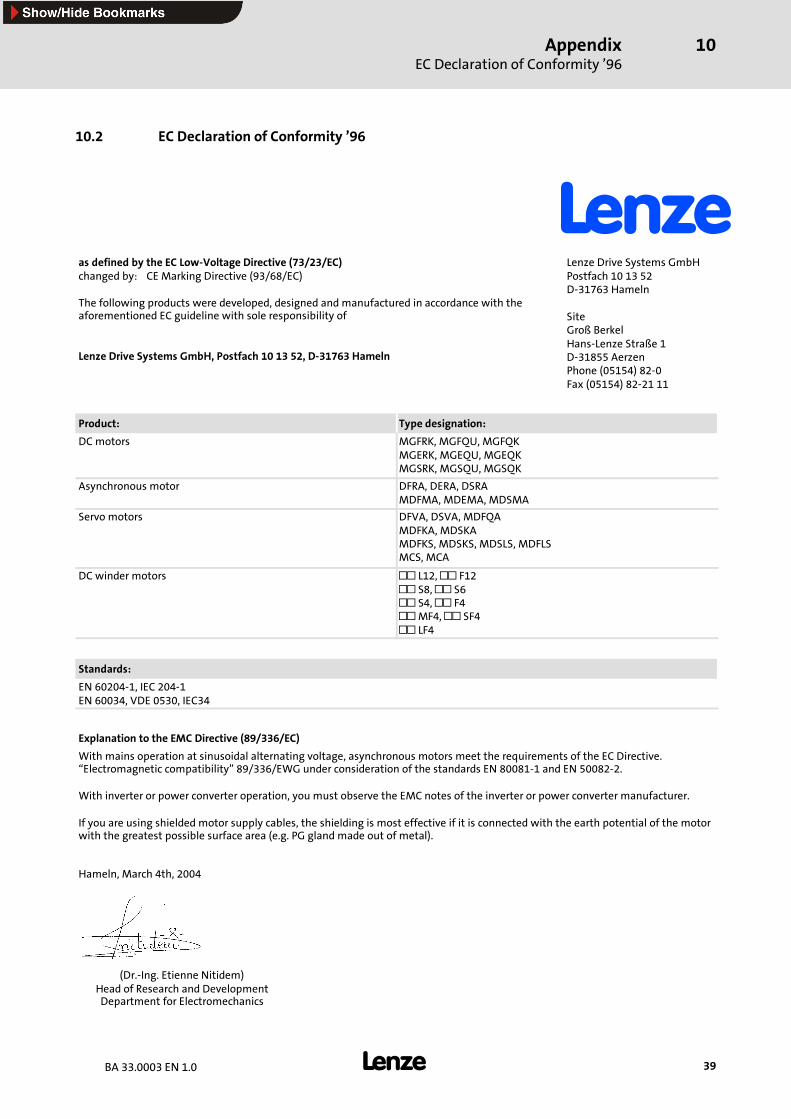
10.2 EC Declaration of Conformity ’96
as defined by the EC Low-Voltage Directive (73/23/EC)changed by: CE Marking Directive (93/68/EC)
The following products were developed, designed and manufactured in accordance with theaforementioned EC guideline with sole responsibility of
Lenze Drive Systems GmbH, Postfach 10 13 52, D-31763 Hameln
Lenze Drive Systems GmbHPostfach 10 13 52D-31763 Hameln
SiteGroß BerkelHans-Lenze Straße 1D-31855 AerzenPhone (05154) 82-0Fax (05154) 82-21 11
Product: Type designation:
DCmotors MGFRK, MGFQU, MGFQKMGERK, MGEQU, MGEQKMGSRK, MGSQU, MGSQK
Asynchronous motor DFRA, DERA, DSRAMDFMA, MDEMA, MDSMA
Servo motors DFVA, DSVA, MDFQAMDFKA, MDSKAMDFKS, MDSKS, MDSLS, MDFLSMCS, MCA
DC winder motors L12, F12S8, S6S4, F4MF4, SF4LF4
Standards:
EN 60204-1, IEC 204-1EN 60034, VDE 0530, IEC34
Explanation to the EMC Directive (89/336/EC)
With mains operation at sinusoidal alternating voltage, asynchronous motors meet the requirements of the EC Directive.“Electromagnetic compatibility” 89/336/EWG under consideration of the standards EN 80081-1 and EN 50082-2.
With inverter or power converter operation, you must observe the EMC notes of the inverter or power converter manufacturer.
If you are using shielded motor supply cables, the shielding is most effective if it is connected with the earth potential of the motorwith the greatest possible surface area (e.g. PG gland made out of metal).
Hameln, March 4th, 2004
(Dr.-Ing. Etienne Nitidem)Head of Research and DevelopmentDepartment for Electromechanics
Lenze Drive Systems GmbHHans-Lenze-Straße 131855 AerzenGermany
BA 33.0003 1.0 04/2004 TD09 2004
+49 (0) 51 54 82-0Service 00 80 00 24 4 68 77 (24 h helpline)Service +49 (0) 51 54 82-1112
E-Mail [email protected] www.lenze.com
10 9 8 7 6 5 4 3 2 1