Embed Size (px)
Citation preview
/ Battery Charging Systems / Welding Technology / Solar Electronics
42,0426,0099,EA 015-10022014
Fronius IG Plus V3.0-1 / 3.8-1 / 5.0-1 / 6.0-1 / 7.5-110.0-1 / 10.0-3 / 11.4-1 / 11.4-312.0-3
Operating Instructions
Inverter for grid-connected photo-voltaic systemsE
N-U
S
1
EN-U
S
Dear reader,
Introduction Thank you for the trust you have placed in our company and congratulations on buying this high-quality Fronius product. These instructions will help you familiarize yourself with the product. Reading the instructions carefully will enable you to learn about the many different features it has to offer. This will allow you to take full advantage of all it's features and ben-efits.
Please also note the safety rules to ensure greater safety when using the product. Careful handling of the product will repay you with years of safe and reliable operation. These are essential prerequisites for excellent results.
3
EN-U
S
General These operating instructions contain important instructions for the Fronius IG Plus that must be followed during installation and maintenance of the inverter.
The Fronius IG Plus is designed and tested according to international safety requirements, but as with all electrical and electronic equipment, certain precautions must be observed when installing and/or operating the Fronius IG Plus.To reduce the risk of personal injury and to ensure the safe installation and operation of the Fronius IG Plus, you must carefully read and follow all instructions and safety instruc-tions in these operating instructions.
Failure to follow these instructions and other relevant safety procedures may result in void-ing of the warranty and/or damage to the inverter or other property!
Safety instruc-tions
The following section "Safety instructions" contains various warnings. A Warning describes a hazard to equipment or personnel. It calls attention to a procedure or practice, which, if not correctly performed or adhered to, could result in damage to or destruction of part or all of the Fronius inverter and/or other equipment connected to the Fronius inverter or per-sonal injury.
Electrical installa-tions
All electrical installations must be carried out in accordance with the National Electrical Code, ANSI/NFPA 70, and any other codes and regulations applicable to the installation site.
For installations in Canada, the installations must be done in accordance with applicable Canadian standards.
IMPORTANT SAFETYINSTRUCTIONS
SAVE THESE INSTRUCTIONS
5
EN-U
S
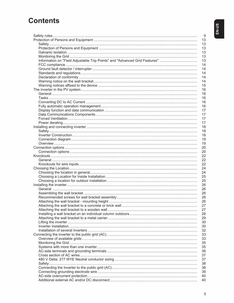
Contents
Safety rules ................................................................................................................................................ 9Protection of Persons and Equipment ....................................................................................................... 13
Safety.................................................................................................................................................... 13Protection of Persons and Equipment .................................................................................................. 13Galvanic isolation.................................................................................................................................. 13Monitoring the Grid ............................................................................................................................... 13Information on "Field Adjustable Trip Points" and "Advanced Grid Features" ..................................... 13FCC compliance ................................................................................................................................... 14Ground fault detector / interrupter......................................................................................................... 14Standards and regulations .................................................................................................................... 14Declaration of conformity ...................................................................................................................... 14Warning notice on the wall bracket ....................................................................................................... 14Warning notices affixed to the device ................................................................................................... 15
The inverter in the PV system.................................................................................................................... 16General ................................................................................................................................................. 16Tasks .................................................................................................................................................... 16Converting DC to AC Current ............................................................................................................... 16Fully automatic operation management................................................................................................ 16Display function and data communication ............................................................................................ 17Data Communications Components ..................................................................................................... 17Forced Ventilation ................................................................................................................................. 17Power derating...................................................................................................................................... 17
Installing and connecting inverter .............................................................................................................. 18Safety.................................................................................................................................................... 18Inverter Construction............................................................................................................................. 18Connection diagram.............................................................................................................................. 19Overview............................................................................................................................................... 19
Connection options .................................................................................................................................... 20Connection options ............................................................................................................................... 20
Knockouts .................................................................................................................................................. 22General ................................................................................................................................................. 22Knockouts for wire inputs...................................................................................................................... 22
Choosing the Location ............................................................................................................................... 24Choosing the location in general........................................................................................................... 24Choosing a Location for Inside Installation ........................................................................................... 25Choosing a location for outdoor installation .......................................................................................... 25
Installing the inverter.................................................................................................................................. 26General ................................................................................................................................................ 26Assembling the wall bracket ................................................................................................................. 26Recommended screws for wall bracket assembly ................................................................................ 26Attaching the wall bracket - mounting height ........................................................................................ 26Attaching the wall bracket to a concrete or brick wall ........................................................................... 27Attaching the wall bracket to a wooden wall ......................................................................................... 27Installing a wall bracket on an individual column outdoors ................................................................... 28Attaching the wall bracket to a metal carrier ......................................................................................... 29Lifting the inverter ................................................................................................................................. 30Inverter installation................................................................................................................................ 30Installation of several inverters ............................................................................................................. 32
Connecting the inverter to the public grid (AC) .......................................................................................... 33Overview of available grids ................................................................................................................... 33Monitoring the Grid ............................................................................................................................... 35Systems with more than one inverter.................................................................................................... 35AC-side terminals and grounding terminals .......................................................................................... 36Cross section of AC wires..................................................................................................................... 37480 V Delta: 277 WYE Neutral conductor sizing .................................................................................. 37Safety.................................................................................................................................................... 38Connecting the Inverter to the public grid (AC)..................................................................................... 38Connecting grounding electrode wire ................................................................................................... 39AC-side overcurrent protection ............................................................................................................. 40Additional external AC and/or DC disconnect....................................................................................... 40
6
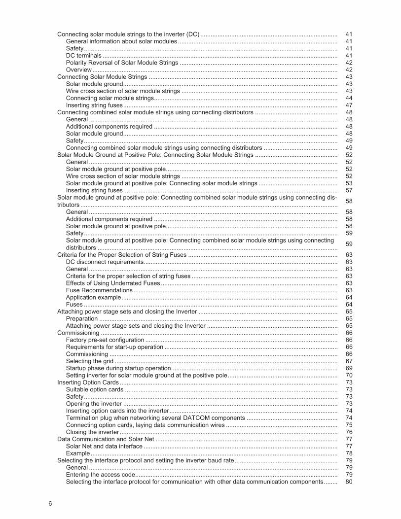
Connecting solar module strings to the inverter (DC) ................................................................................ 41General information about solar modules ............................................................................................. 41Safety.................................................................................................................................................... 41DC terminals ......................................................................................................................................... 41Polarity Reversal of Solar Module Strings ............................................................................................ 42Overview............................................................................................................................................... 42
Connecting Solar Module Strings .............................................................................................................. 43Solar module ground............................................................................................................................. 43Wire cross section of solar module strings ........................................................................................... 43Connecting solar module strings........................................................................................................... 44Inserting string fuses............................................................................................................................. 47
Connecting combined solar module strings using connecting distributors ................................................ 48General ................................................................................................................................................. 48Additional components required ........................................................................................................... 48Solar module ground............................................................................................................................. 48Safety.................................................................................................................................................... 49Connecting combined solar module strings using connecting distributors ........................................... 49
Solar Module Ground at Positive Pole: Connecting Solar Module Strings ................................................ 52General ................................................................................................................................................. 52Solar module ground at positive pole.................................................................................................... 52Wire cross section of solar module strings ........................................................................................... 52Solar module ground at positive pole: Connecting solar module strings .............................................. 53Inserting string fuses............................................................................................................................. 57
Solar module ground at positive pole: Connecting combined solar module strings using connecting dis-tributors ...................................................................................................................................................... 58
General ................................................................................................................................................. 58Additional components required ........................................................................................................... 58Solar module ground at positive pole.................................................................................................... 58Safety.................................................................................................................................................... 59Solar module ground at positive pole: Connecting combined solar module strings using connecting distributors ............................................................................................................................................ 59
Criteria for the Proper Selection of String Fuses ....................................................................................... 63DC disconnect requirements................................................................................................................. 63General ................................................................................................................................................. 63Criteria for the proper selection of string fuses ..................................................................................... 63Effects of Using Underrated Fuses ....................................................................................................... 63Fuse Recommendations ....................................................................................................................... 63Application example.............................................................................................................................. 64Fuses .................................................................................................................................................... 64
Attaching power stage sets and closing the Inverter ................................................................................. 65Preparation ........................................................................................................................................... 65Attaching power stage sets and closing the Inverter ............................................................................ 65
Commissioning .......................................................................................................................................... 66Factory pre-set configuration ................................................................................................................ 66Requirements for start-up operation ..................................................................................................... 66Commissioning ..................................................................................................................................... 66Selecting the grid .................................................................................................................................. 67Startup phase during startup operation................................................................................................. 69Setting inverter for solar module ground at the positive pole................................................................ 70
Inserting Option Cards ............................................................................................................................... 73Suitable option cards ............................................................................................................................ 73Safety.................................................................................................................................................... 73Opening the inverter ............................................................................................................................. 73Inserting option cards into the inverter.................................................................................................. 74Termination plug when networking several DATCOM components ..................................................... 74Connecting option cards, laying data communication wires ................................................................. 75Closing the inverter ............................................................................................................................... 76
Data Communication and Solar Net .......................................................................................................... 77Solar Net and data interface ................................................................................................................. 77Example ................................................................................................................................................ 78
Selecting the interface protocol and setting the inverter baud rate............................................................ 79General ................................................................................................................................................. 79Entering the access code...................................................................................................................... 79Selecting the interface protocol for communication with other data communication components........ 80
7
EN-U
S
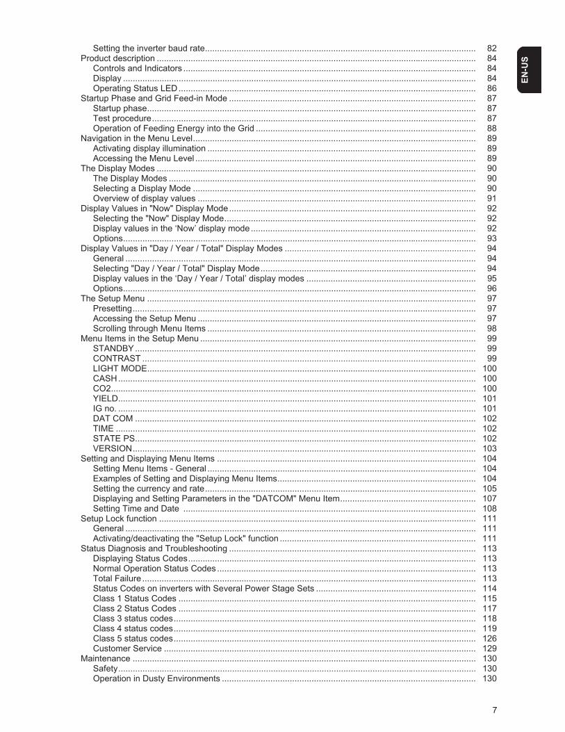
Setting the inverter baud rate................................................................................................................ 82Product description .................................................................................................................................... 84
Controls and Indicators ......................................................................................................................... 84Display .................................................................................................................................................. 84Operating Status LED........................................................................................................................... 86
Startup Phase and Grid Feed-in Mode ...................................................................................................... 87Startup phase........................................................................................................................................ 87Test procedure...................................................................................................................................... 87Operation of Feeding Energy into the Grid ........................................................................................... 88
Navigation in the Menu Level..................................................................................................................... 89Activating display illumination ............................................................................................................... 89Accessing the Menu Level .................................................................................................................... 89
The Display Modes .................................................................................................................................... 90The Display Modes ............................................................................................................................... 90Selecting a Display Mode ..................................................................................................................... 90Overview of display values ................................................................................................................... 91
Display Values in "Now" Display Mode...................................................................................................... 92Selecting the "Now" Display Mode........................................................................................................ 92Display values in the ‘Now’ display mode ............................................................................................. 92Options.................................................................................................................................................. 93
Display Values in "Day / Year / Total" Display Modes ............................................................................... 94General ................................................................................................................................................. 94Selecting "Day / Year / Total" Display Mode......................................................................................... 94Display values in the ‘Day / Year / Total’ display modes ...................................................................... 95Options.................................................................................................................................................. 96
The Setup Menu ........................................................................................................................................ 97Presetting.............................................................................................................................................. 97Accessing the Setup Menu ................................................................................................................... 97Scrolling through Menu Items ............................................................................................................... 98
Menu Items in the Setup Menu .................................................................................................................. 99STANDBY............................................................................................................................................. 99CONTRAST .......................................................................................................................................... 99LIGHT MODE........................................................................................................................................ 100CASH.................................................................................................................................................... 100CO2....................................................................................................................................................... 100YIELD.................................................................................................................................................... 101IG no. .................................................................................................................................................... 101DAT COM ............................................................................................................................................. 102TIME ..................................................................................................................................................... 102STATE PS............................................................................................................................................. 102VERSION.............................................................................................................................................. 103
Setting and Displaying Menu Items ........................................................................................................... 104Setting Menu Items - General ............................................................................................................... 104Examples of Setting and Displaying Menu Items.................................................................................. 104Setting the currency and rate................................................................................................................ 105Displaying and Setting Parameters in the "DATCOM" Menu Item........................................................ 107Setting Time and Date ......................................................................................................................... 108
Setup Lock function ................................................................................................................................... 111General ................................................................................................................................................. 111Activating/deactivating the "Setup Lock" function ................................................................................. 111
Status Diagnosis and Troubleshooting ...................................................................................................... 113Displaying Status Codes....................................................................................................................... 113Normal Operation Status Codes ........................................................................................................... 113Total Failure .......................................................................................................................................... 113Status Codes on inverters with Several Power Stage Sets .................................................................. 114Class 1 Status Codes ........................................................................................................................... 115Class 2 Status Codes ........................................................................................................................... 117Class 3 status codes............................................................................................................................. 118Class 4 status codes............................................................................................................................. 119Class 5 status codes............................................................................................................................. 126Customer Service ................................................................................................................................. 129
Maintenance .............................................................................................................................................. 130Safety.................................................................................................................................................... 130Operation in Dusty Environments ......................................................................................................... 130
8
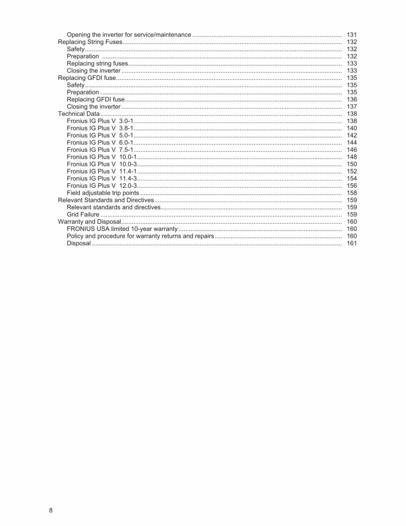
Opening the inverter for service/maintenance ...................................................................................... 131Replacing String Fuses.............................................................................................................................. 132
Safety.................................................................................................................................................... 132Preparation .......................................................................................................................................... 132Replacing string fuses........................................................................................................................... 133Closing the inverter ............................................................................................................................... 133
Replacing GFDI fuse.................................................................................................................................. 135Safety.................................................................................................................................................... 135Preparation ........................................................................................................................................... 135Replacing GFDI fuse............................................................................................................................. 136Closing the inverter ............................................................................................................................... 137
Technical Data ........................................................................................................................................... 138Fronius IG Plus V 3.0-1........................................................................................................................ 138Fronius IG Plus V 3.8-1........................................................................................................................ 140Fronius IG Plus V 5.0-1........................................................................................................................ 142Fronius IG Plus V 6.0-1........................................................................................................................ 144Fronius IG Plus V 7.5-1........................................................................................................................ 146Fronius IG Plus V 10.0-1...................................................................................................................... 148Fronius IG Plus V 10.0-3...................................................................................................................... 150Fronius IG Plus V 11.4-1...................................................................................................................... 152Fronius IG Plus V 11.4-3...................................................................................................................... 154Fronius IG Plus V 12.0-3...................................................................................................................... 156Field adjustable trip points .................................................................................................................... 158
Relevant Standards and Directives............................................................................................................ 159Relevant standards and directives........................................................................................................ 159Grid Failure ........................................................................................................................................... 159
Warranty and Disposal............................................................................................................................... 160FRONIUS USA limited 10-year warranty .............................................................................................. 160Policy and procedure for warranty returns and repairs ......................................................................... 160Disposal ................................................................................................................................................ 161
9
EN-U
S
Safety rules
Safety Rules Ex-planation
If you see any of the symbols depicted in the "Safety rules," special care is required.
General
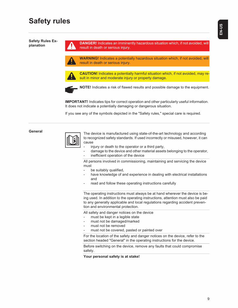
DANGER! Indicates an imminently hazardous situation which, if not avoided, will result in death or serious injury.
WARNING! Indicates a potentially hazardous situation which, if not avoided, will result in death or serious injury.
CAUTION! Indicates a potentially harmful situation which, if not avoided, may re-sult in minor and moderate injury or property damage.
NOTE! Indicates a risk of flawed results and possible damage to the equipment.
IMPORTANT! Indicates tips for correct operation and other particularly useful information. It does not indicate a potentially damaging or dangerous situation.
The device is manufactured using state-of-the-art technology and according to recognized safety standards. If used incorrectly or misused, however, it can cause- injury or death to the operator or a third party,- damage to the device and other material assets belonging to the operator,- inefficient operation of the deviceAll persons involved in commissioning, maintaining and servicing the device must- be suitably qualified,- have knowledge of and experience in dealing with electrical installations
and- read and follow these operating instructions carefully
The operating instructions must always be at hand wherever the device is be-ing used. In addition to the operating instructions, attention must also be paid to any generally applicable and local regulations regarding accident preven-tion and environmental protection.All safety and danger notices on the device - must be kept in a legible state - must not be damaged/marked - must not be removed- must not be covered, pasted or painted overFor the location of the safety and danger notices on the device, refer to the section headed "General" in the operating instructions for the device.Before switching on the device, remove any faults that could compromise safety.Your personal safety is at stake!
10
Utilization in Ac-cordance with "Intended Pur-pose"
Environmental Conditions
Qualified Service Engineers
Safety Measures at the Installation Location
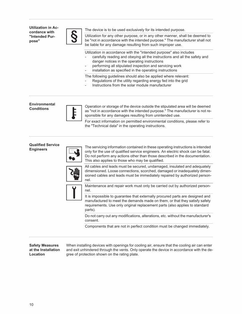
When installing devices with openings for cooling air, ensure that the cooling air can enter and exit unhindered through the vents. Only operate the device in accordance with the de-gree of protection shown on the rating plate.
The device is to be used exclusively for its intended purpose. Utilization for any other purpose, or in any other manner, shall be deemed to be "not in accordance with the intended purpose." The manufacturer shall not be liable for any damage resulting from such improper use.
Utilization in accordance with the "intended purpose" also includes - carefully reading and obeying all the instructions and all the safety and
danger notices in the operating instructions- performing all stipulated inspection and servicing work- installation as specified in the operating instructionsThe following guidelines should also be applied where relevant:- Regulations of the utility regarding energy fed into the grid- Instructions from the solar module manufacturer
Operation or storage of the device outside the stipulated area will be deemed as "not in accordance with the intended purpose." The manufacturer is not re-sponsible for any damages resulting from unintended use.For exact information on permitted environmental conditions, please refer to the "Technical data" in the operating instructions.
The servicing information contained in these operating instructions is intended only for the use of qualified service engineers. An electric shock can be fatal. Do not perform any actions other than those described in the documentation. This also applies to those who may be qualified.All cables and leads must be secured, undamaged, insulated and adequately dimensioned. Loose connections, scorched, damaged or inadequately dimen-sioned cables and leads must be immediately repaired by authorized person-nel.Maintenance and repair work must only be carried out by authorized person-nel.It is impossible to guarantee that externally procured parts are designed and manufactured to meet the demands made on them, or that they satisfy safety requirements. Use only original replacement parts (also applies to standard parts).Do not carry out any modifications, alterations, etc. without the manufacturer's consent.Components that are not in perfect condition must be changed immediately.
11
EN-U
SData Regarding Noise Emission Values
EMC Device Clas-sifications
EMC Measures
Grid Connection
Electrical Installa-tions
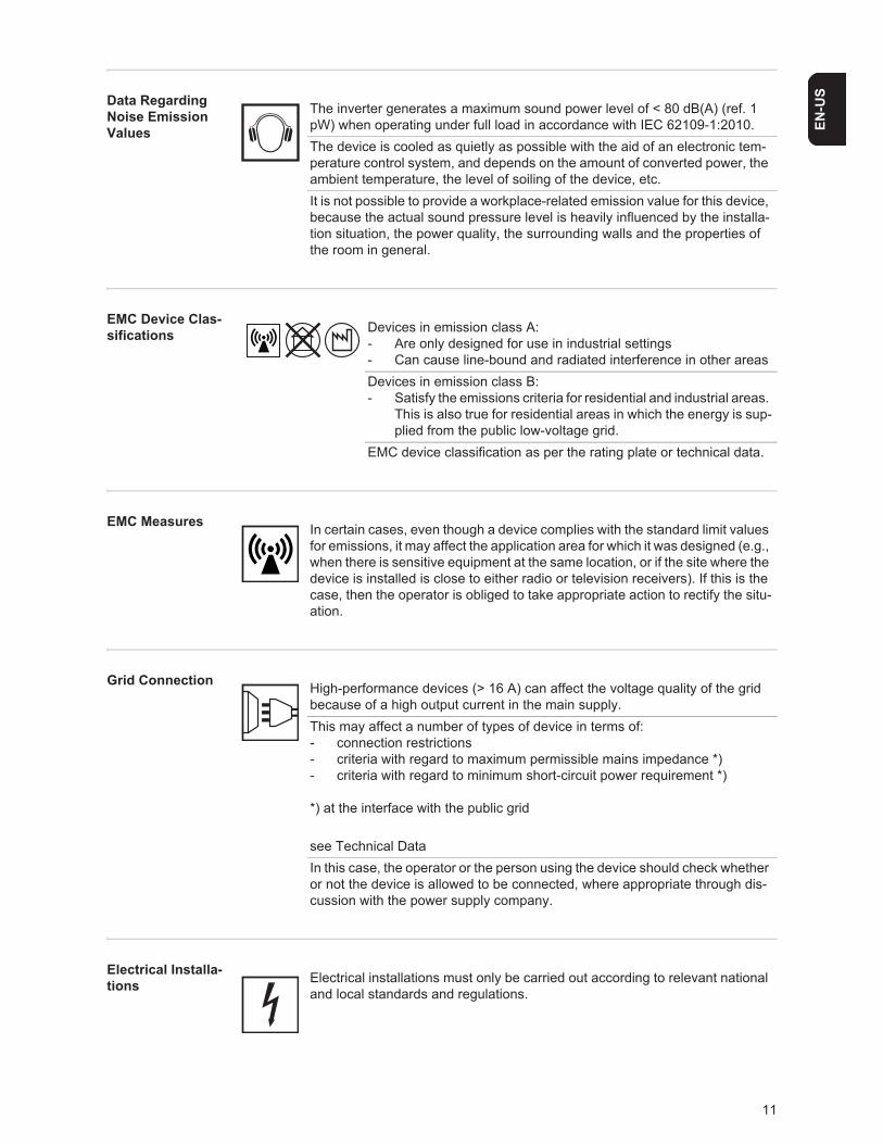
The inverter generates a maximum sound power level of < 80 dB(A) (ref. 1 pW) when operating under full load in accordance with IEC 62109-1:2010.The device is cooled as quietly as possible with the aid of an electronic tem-perature control system, and depends on the amount of converted power, the ambient temperature, the level of soiling of the device, etc.It is not possible to provide a workplace-related emission value for this device, because the actual sound pressure level is heavily influenced by the installa-tion situation, the power quality, the surrounding walls and the properties of the room in general.
Devices in emission class A:- Are only designed for use in industrial settings- Can cause line-bound and radiated interference in other areasDevices in emission class B:- Satisfy the emissions criteria for residential and industrial areas.
This is also true for residential areas in which the energy is sup-plied from the public low-voltage grid.
EMC device classification as per the rating plate or technical data.
In certain cases, even though a device complies with the standard limit values for emissions, it may affect the application area for which it was designed (e.g., when there is sensitive equipment at the same location, or if the site where the device is installed is close to either radio or television receivers). If this is the case, then the operator is obliged to take appropriate action to rectify the situ-ation.
High-performance devices (> 16 A) can affect the voltage quality of the grid because of a high output current in the main supply.This may affect a number of types of device in terms of:- connection restrictions- criteria with regard to maximum permissible mains impedance *)- criteria with regard to minimum short-circuit power requirement *)
*) at the interface with the public grid
see Technical DataIn this case, the operator or the person using the device should check whether or not the device is allowed to be connected, where appropriate through dis-cussion with the power supply company.
Electrical installations must only be carried out according to relevant national and local standards and regulations.
12
Protective Mea-sures against ESD
Safety measures in normal opera-tion
Safety symbols
Disposal
Backup
Copyright
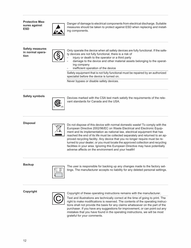
Danger of damage to electrical components from electrical discharge. Suitable measures should be taken to protect against ESD when replacing and install-ing components.
Only operate the device when all safety devices are fully functional. If the safe-ty devices are not fully functional, there is a risk of- injury or death to the operator or a third party- damage to the device and other material assets belonging to the operat-
ing company- inefficient operation of the deviceSafety equipment that is not fully functional must be repaired by an authorized specialist before the device is turned on.Never bypass or disable safety devices.
Devices marked with the CSA test mark satisfy the requirements of the rele-vant standards for Canada and the USA.
Do not dispose of this device with normal domestic waste! To comply with the European Directive 2002/96/EC on Waste Electrical and Electronic Equip-ment and its implementation as national law, electrical equipment that has reached the end of its life must be collected separately and returned to an ap-proved recycling facility. Any device that you no longer require must be re-turned to your dealer, or you must locate the approved collection and recycling facilities in your area. Ignoring this European Directive may have potentially adverse affects on the environment and your health!
The user is responsible for backing up any changes made to the factory set-tings. The manufacturer accepts no liability for any deleted personal settings.
Copyright of these operating instructions remains with the manufacturer.Text and illustrations are technically correct at the time of going to print. The right to make modifications is reserved. The contents of the operating instruc-tions shall not provide the basis for any claims whatsoever on the part of the purchaser. If you have any suggestions for improvement, or can point out any mistakes that you have found in the operating instructions, we will be most grateful for your comments.
13
EN-U
S
Protection of Persons and Equipment
Safety
Protection of Per-sons and Equip-ment
The design and function of the inverter offer a maximum level of safety, both during instal-lation as well as operation.
The inverter provides operator and equipment protection through:a) galvanic isolationb) monitoring the grid
Galvanic isolation The inverter is equipped with a high frequency transformer that ensures galvanic isolation between the DC side and the grid, thus ensuring the highest possible safety.
Monitoring the Grid
Whenever conditions in the electric grid are inconsistent with standard conditions (for ex-ample, grid switch-off, interruption), the inverter will immediately stop operating and inter-rupt the supply of power into the grid.
Grid monitoring is carried out using:- Voltage monitoring- Frequency monitoring- Monitoring islanding conditions
Information on "Field Adjustable Trip Points" and "Advanced Grid Features"
The inverter is equipped with field adjustable trip points and advanced grid features. For further information, please contact Fronius technical support at the following e-mail ad-dress: [email protected].
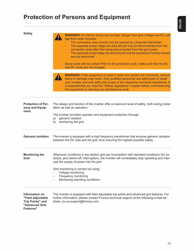
WARNING! An electric shock can be fatal. Danger from grid voltage and DC volt-age from solar modules.- The connection area should only be opened by a licensed electrician.- The separate power stage set area should only be disconnected from the
connection area after first being disconnected from the grid power. - The separate power stage set area should only be opened by Fronius-trained
service personnel.
Never work with live wires! Prior to all connection work, make sure that the AC and DC wires are not charged.
WARNING! If the equipment is used or tasks are carried out incorrectly, serious injury or damage may result. Only qualified personnel are authorized to install your inverter and only within the scope of the respective technical regulations. It is essential that you read the "Safety regulations" chapter before commissioning the equipment or carrying out maintenance work.
14
FCC compliance
Ground fault de-tector / interrupt-er
The inverter is equipped with a ground fault detection and interruption (GFDI) circuit as re-quired by UL 1741 and the National Electrical code.Depending on the system configuration either the PV array’s negative or positive conductor is connected to the grounding system in the inverter. If a ground fault occurs in the DC wir-ing, the inverter disconnects from the grid.
Standards and regulations
Your inverter complies with the requirements for the following standards "Inverters, con-verters and controllers for use in independent power systems":- UL1741-2005- IEEE 1547-2003- IEEE 1547.1- ANSI / IEEE C62.41- C22.2 No. 107.1-01 (Sep. 2001)
The ground-fault detection and interruption is in compliance with NEC 690 building code requirements.
Declaration of conformity
Relevant declarations of conformity can be found in the appendix to these operating in-structions.
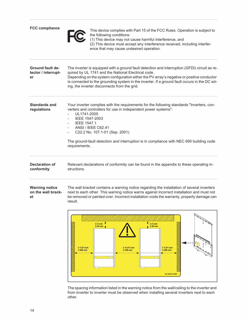
Warning notice on the wall brack-et
The wall bracket contains a warning notice regarding the installation of several inverters next to each other. This warning notice warns against incorrect installation and must not be removed or painted over. Incorrect installation voids the warranty, property damage can result.
The spacing information listed in the warning notice from the wall/ceiling to the inverter and from inverter to inverter must be observed when installing several inverters next to each other.
This device complies with Part 15 of the FCC Rules. Operation is subject to the following conditions:(1) This device may not cause harmful interference, and(2) This device must accept any interference received, including interfer-ence that may cause undesired operation.
15
EN-U
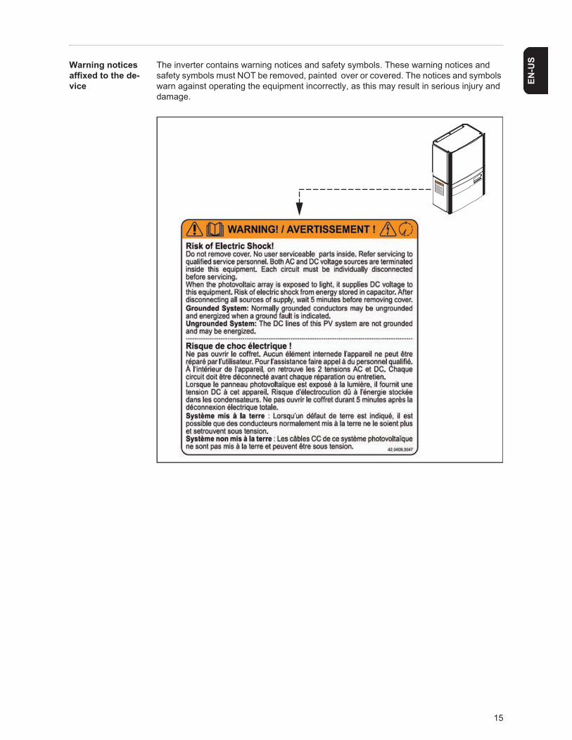
SWarning notices affixed to the de-vice
The inverter contains warning notices and safety symbols. These warning notices and safety symbols must NOT be removed, painted over or covered. The notices and symbols warn against operating the equipment incorrectly, as this may result in serious injury and damage.
16
The inverter in the PV system
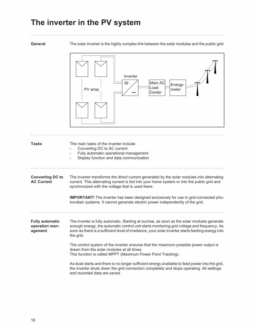
General The solar inverter is the highly complex link between the solar modules and the public grid.
Tasks The main tasks of the inverter include:- Converting DC to AC current- Fully automatic operational management- Display function and data communication
Converting DC to AC Current
The inverter transforms the direct current generated by the solar modules into alternating current. This alternating current is fed into your home system or into the public grid and synchronized with the voltage that is used there.
Fully automatic operation man-agement
The inverter is fully automatic. Starting at sunrise, as soon as the solar modules generate enough energy, the automatic control unit starts monitoring grid voltage and frequency. As soon as there is a sufficient level of irradiance, your solar inverter starts feeding energy into the grid.
The control system of the inverter ensures that the maximum possible power output is drawn from the solar modules at all times. This function is called MPPT (Maximum Power Point Tracking).
As dusk starts and there is no longer sufficient energy available to feed power into the grid, the inverter shuts down the grid connection completely and stops operating. All settings and recorded data are saved.
Inverter
Main ACLoadCenter
Energy-meterPV array
IMPORTANT! The inverter has been designed exclusively for use in grid-connected pho-tovoltaic systems. It cannot generate electric power independently of the grid.
17
EN-U
SDisplay function and data commu-nication
The display on the inverter is the interface between the inverter and the operator. The de-sign of the display is geared towards simple operation and making system data available as long as the inverter operates.
The inverter is equipped with a basic logging function to monitor minimum and maximum data on a daily and a cumulative basis. These values are shown on the display.
A wide range of data communication products allows for many possibilities of recording and viewing data.
Data Communica-tions Compo-nents
The inverter is designed for various data communications components, e.g.:- Data communications components that enable the inverter to communicate with ex-
ternal components as well as other inverters- Datalogger and modem interface as well as an Ethernet/Internet connection (for using
a PC to record and manage data from your photovoltaic system)- Various large-format displays- Fronius Personal Display- Actuators (e.g.: relays, alarms)- Interface cards
Data communications components are available as plug-in cards.
Forced Ventila-tion
The inverter's temperature-controlled, variable-speed fan with ball-bearing support pro-vides:- optimal inverter cooling- efficiency increases- cooler components, thus improving service life- least possible energy consumption and lowest possible noise level- weight reduction due to a reduction of the cooling element surface
Power derating Should there be insufficient heat dissipation in spite of the fan operating at maximum speed (for example, inadequate heat transfer away from the heat sinks), the power will be derated to protect the inverter when the ambient temperature reaches approx. 40 °C and above.
Derating the power reduces the output of the inverter for a short period sufficient to ensure that the temperature will not exceed the permissible limit.Your inverter will remain ready for operation as long as possible without any interruption.
18
Installing and connecting inverter
Safety
Inverter Con-struction
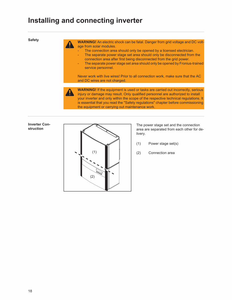
The power stage set and the connection area are separated from each other for de-livery.
(1) Power stage set(s)
(2) Connection area
WARNING! An electric shock can be fatal. Danger from grid voltage and DC volt-age from solar modules.- The connection area should only be opened by a licensed electrician.- The separate power stage set area should only be disconnected from the
connection area after first being disconnected from the grid power. - The separate power stage set area should only be opened by Fronius-trained
service personnel.
Never work with live wires! Prior to all connection work, make sure that the AC and DC wires are not charged.
WARNING! If the equipment is used or tasks are carried out incorrectly, serious injury or damage may result. Only qualified personnel are authorized to install your inverter and only within the scope of the respective technical regulations. It is essential that you read the "Safety regulations" chapter before commissioning the equipment or carrying out maintenance work.
(1)
(2)
19
EN-U
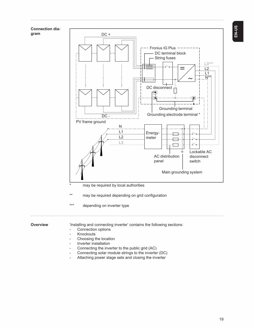
SConnection dia-gram
* may be required by local authorities
** may be required depending on grid configuration
*** depending on inverter type
Overview ‘Installing and connecting inverter’ contains the following sections:- Connection options- Knockouts- Choosing the location- Inverter installation- Connecting the inverter to the public grid (AC)- Connecting solar module strings to the inverter (DC)- Attaching power stage sets and closing the inverter
Fronius IG Plus
Energy-meter
AC distributionpanel
DC disconnect
DC terminal blockString fuses
DC +
DC -PV frame ground
L1L2
N
Grounding terminalGrounding electrode terminal *
L1N**
L2
L3
L3***
Main grounding system
Lockable ACdisconnectswitch
20
Connection options
Connection op-tions
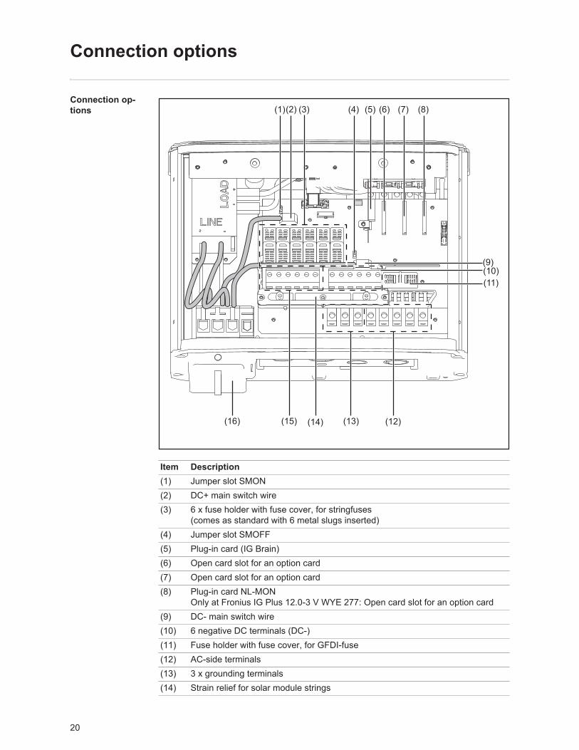
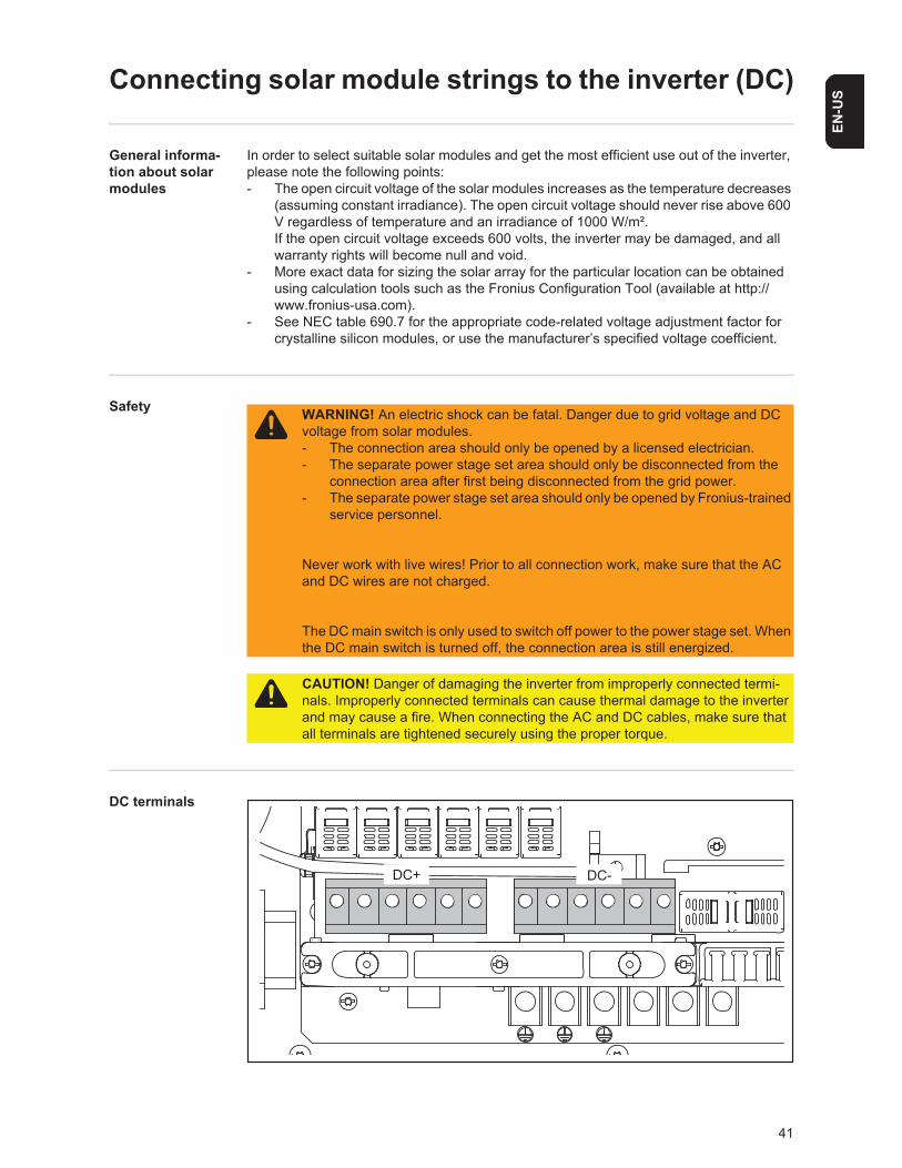
Item Description(1) Jumper slot SMON (2) DC+ main switch wire(3) 6 x fuse holder with fuse cover, for stringfuses
(comes as standard with 6 metal slugs inserted)(4) Jumper slot SMOFF(5) Plug-in card (IG Brain)(6) Open card slot for an option card (7) Open card slot for an option card(8) Plug-in card NL-MON
Only at Fronius IG Plus 12.0-3 V WYE 277: Open card slot for an option card(9) DC- main switch wire(10) 6 negative DC terminals (DC-)(11) Fuse holder with fuse cover, for GFDI-fuse(12) AC-side terminals (13) 3 x grounding terminals(14) Strain relief for solar module strings
21
EN-U
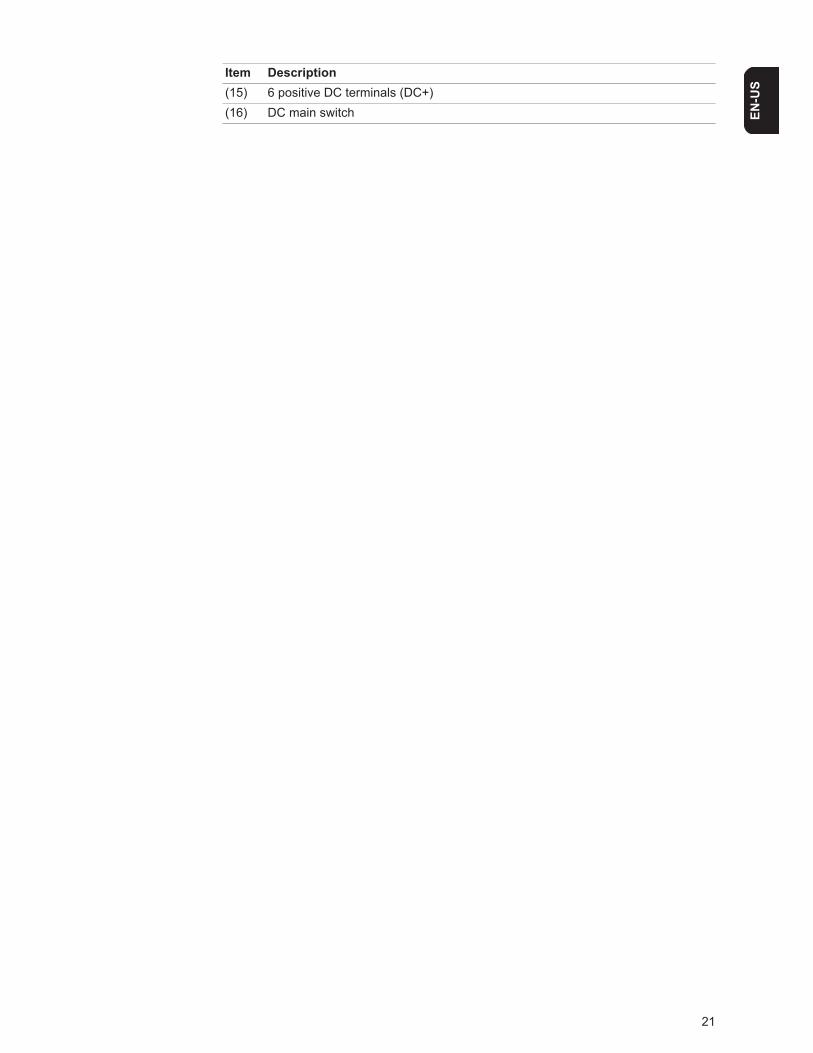
S(15) 6 positive DC terminals (DC+)(16) DC main switch
Item Description
22
Knockouts
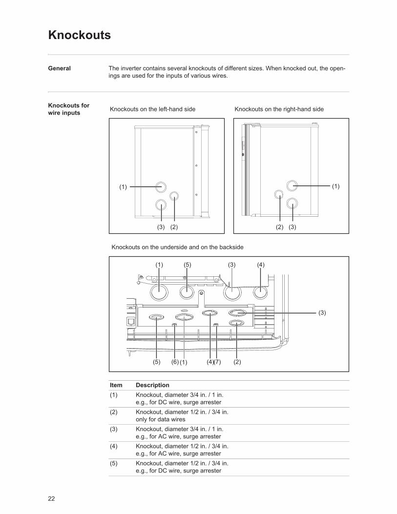
General The inverter contains several knockouts of different sizes. When knocked out, the open-ings are used for the inputs of various wires.
Knockouts for wire inputs Knockouts on the left-hand side Knockouts on the right-hand side
Knockouts on the underside and on the backside
Item Description(1) Knockout, diameter 3/4 in. / 1 in.
e.g., for DC wire, surge arrester(2) Knockout, diameter 1/2 in. / 3/4 in.
only for data wires(3) Knockout, diameter 3/4 in. / 1 in.
e.g., for AC wire, surge arrester(4) Knockout, diameter 1/2 in. / 3/4 in.
e.g., for AC wire, surge arrester(5) Knockout, diameter 1/2 in. / 3/4 in.
e.g., for DC wire, surge arrester
(2)
(1)
(3)
(1)
(3)(2)
(1)
(2)
(3) (4)(5)
(1)(5)
(3)
(4)(6) (7)
23
EN-U
S(6) FTX 25 fixing screw(7) FTX 25 fixing screw
NOTE! When using back wire inputs:- seal enclosure as per NEMA 3R before outside operationn
NOTE!- The larger knockouts should only be removed from the outside in.- The smaller knockouts should be removed from the inside out.- Only remove the number of knockouts required for the available wire inputs.
CAUTION! Danger of damaging the plastic base when removing the knockouts on the bottom.- Before removing, remove the 3 fixing screws (6) and (7)- Remove the metal insert from the plastic base- Remove the required knockouts- Replace the metal insert into the plastic base- Secure the metal insert using the 3 fixing screws (6) and (7)
Item Description
24
Choosing the Location
Choosing the lo-cation in general
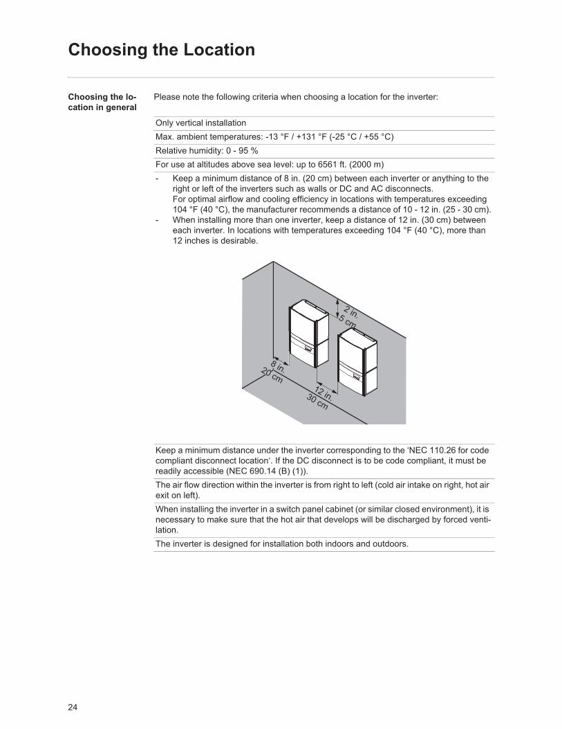
Please note the following criteria when choosing a location for the inverter:
Only vertical installationMax. ambient temperatures: -13 °F / +131 °F (-25 °C / +55 °C)Relative humidity: 0 - 95 %For use at altitudes above sea level: up to 6561 ft. (2000 m)- Keep a minimum distance of 8 in. (20 cm) between each inverter or anything to the
right or left of the inverters such as walls or DC and AC disconnects.For optimal airflow and cooling efficiency in locations with temperatures exceeding 104 °F (40 °C), the manufacturer recommends a distance of 10 - 12 in. (25 - 30 cm).
- When installing more than one inverter, keep a distance of 12 in. (30 cm) between each inverter. In locations with temperatures exceeding 104 °F (40 °C), more than 12 inches is desirable.
Keep a minimum distance under the inverter corresponding to the ‘NEC 110.26 for code compliant disconnect location‘. If the DC disconnect is to be code compliant, it must be readily accessible (NEC 690.14 (B) (1)).The air flow direction within the inverter is from right to left (cold air intake on right, hot air exit on left).When installing the inverter in a switch panel cabinet (or similar closed environment), it is necessary to make sure that the hot air that develops will be discharged by forced venti-lation.The inverter is designed for installation both indoors and outdoors.
2 in.5 cm
12 in.30 cm
8 in.20 cm
25
EN-U
SChoosing a Loca-tion for Inside In-stallation
Choosing a loca-tion for outdoor installation
During certain operation phases the inverter may produce a slight noise. For this reason it should not be installed in an occupied living area.Do not install the inverter in:- areas with large amounts of dust- areas with large amounts of conducting dust particles (e.g., iron filings)- areas with corrosive gases, acids or salts- areas where there is an increased risk of accidents, e.g., from farm animals (horses,
cattle, sheep, pigs, etc.)- stables or adjoining areas- storage areas for hay, straw, chaff, animal feed, fertilizers, etc.- storage or processing areas for fruit, vegetables or winegrowing products- areas used in the preparation of grain, green fodder or animal feeds- greenhouses
NEMA 3R protection means that the inverter is not susceptible to water spray from any direction.However, the manufacturer recommends, if possible, that the inverter not be exposed to direct moisture or to a direct water jet (e.g., from sprinklers).In order to protect the display, the inverter should not be exposed to direct sunlight. Ide-ally, the inverter should be installed in a protected location, e.g., near the solar modules or under a roof overhang.Do not install the inverter:- where it can be exposed to ammonia, corrosive gasses, acids or salts (e.g., fertilizer
storage areas, vent openings of livestock stables, chemical plants, tanneries)
26
Installing the inverter
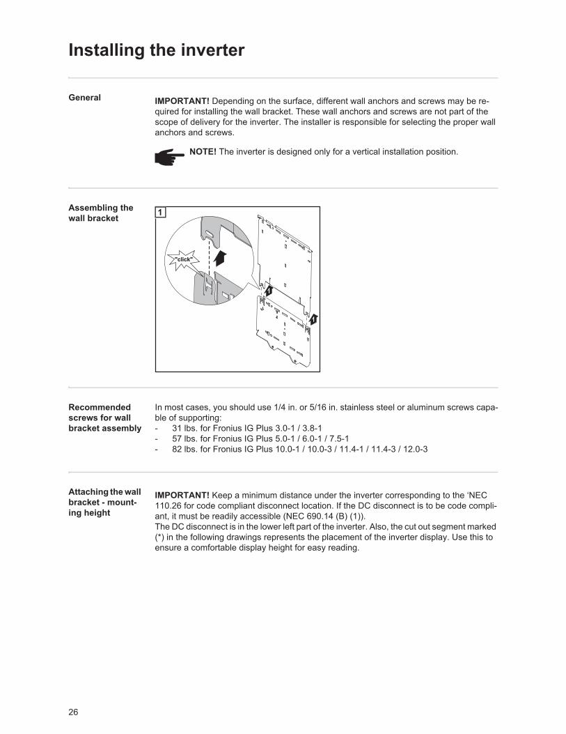
General
Assembling the wall bracket
Recommended screws for wall bracket assembly
In most cases, you should use 1/4 in. or 5/16 in. stainless steel or aluminum screws capa-ble of supporting:- 31 lbs. for Fronius IG Plus 3.0-1 / 3.8-1 - 57 lbs. for Fronius IG Plus 5.0-1 / 6.0-1 / 7.5-1 - 82 lbs. for Fronius IG Plus 10.0-1 / 10.0-3 / 11.4-1 / 11.4-3 / 12.0-3
Attaching the wall bracket - mount-ing height
IMPORTANT! Depending on the surface, different wall anchors and screws may be re-quired for installing the wall bracket. These wall anchors and screws are not part of the scope of delivery for the inverter. The installer is responsible for selecting the proper wall anchors and screws.
NOTE! The inverter is designed only for a vertical installation position.
"click""click"
1
1
1
IMPORTANT! Keep a minimum distance under the inverter corresponding to the ‘NEC 110.26 for code compliant disconnect location. If the DC disconnect is to be code compli-ant, it must be readily accessible (NEC 690.14 (B) (1)).The DC disconnect is in the lower left part of the inverter. Also, the cut out segment marked (*) in the following drawings represents the placement of the inverter display. Use this to ensure a comfortable display height for easy reading.
27
EN-U
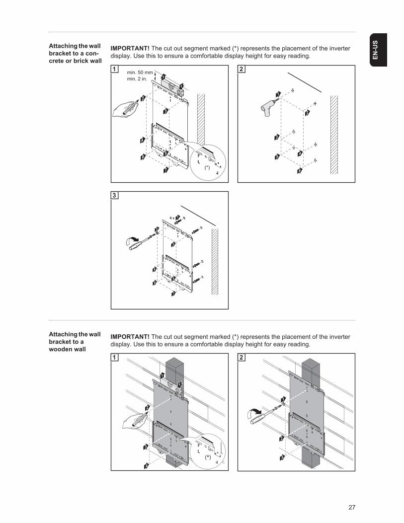
SAttaching the wall bracket to a con-crete or brick wall
Attaching the wall bracket to a wooden wall
IMPORTANT! The cut out segment marked (*) represents the placement of the inverter display. Use this to ensure a comfortable display height for easy reading.
min. 50 mmmin. 2 in.
2
1
1
7
3
5
4
6
(*)
1
22
3
4
1
6
5
2
2
6 x
4
6
7
1
5
23
3
IMPORTANT! The cut out segment marked (*) represents the placement of the inverter display. Use this to ensure a comfortable display height for easy reading.
9
1
1
2
3
4
(*)
1
9
1
2
5
2
28
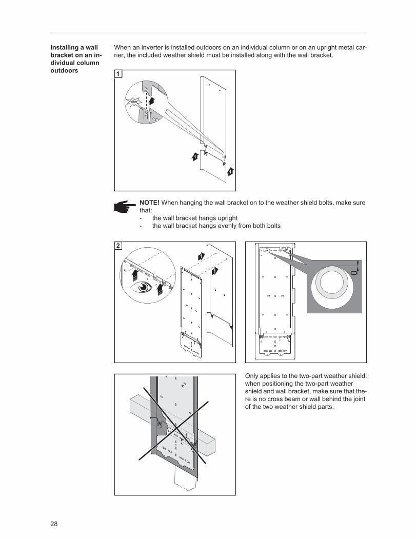
Installing a wall bracket on an in-dividual column outdoors
When an inverter is installed outdoors on an individual column or on an upright metal car-rier, the included weather shield must be installed along with the wall bracket.
Only applies to the two-part weather shield:when positioning the two-part weather shield and wall bracket, make sure that the-re is no cross beam or wall behind the joint of the two weather shield parts.
1
1
"click""click"
1
NOTE! When hanging the wall bracket on to the weather shield bolts, make sure that:- the wall bracket hangs upright- the wall bracket hangs evenly from both bolts
1
1
2
0
29
EN-U
S
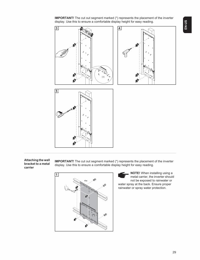
Attaching the wall bracket to a metal carrier
IMPORTANT! The cut out segment marked (*) represents the placement of the inverter display. Use this to ensure a comfortable display height for easy reading.
2
3
4
1
1
3
1
2
3
4
1
2
3
5
IMPORTANT! The cut out segment marked (*) represents the placement of the inverter display. Use this to ensure a comfortable display height for easy reading.
NOTE! When installing using a metal carrier, the inverter should not be exposed to rainwater or
water spray at the back. Ensure proper rainwater or spray water protection.1
4 x
3
4
22
(*)
1
30
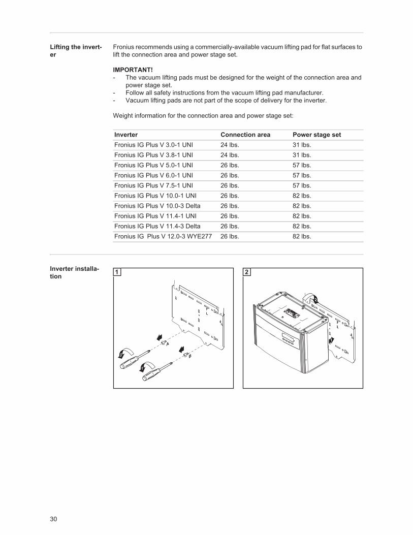
Lifting the invert-er
Fronius recommends using a commercially-available vacuum lifting pad for flat surfaces to lift the connection area and power stage set.
IMPORTANT! - The vacuum lifting pads must be designed for the weight of the connection area and
power stage set.- Follow all safety instructions from the vacuum lifting pad manufacturer.- Vacuum lifting pads are not part of the scope of delivery for the inverter.
Weight information for the connection area and power stage set:
Inverter installa-tion
Inverter Connection area Power stage setFronius IG Plus V 3.0-1 UNI 24 lbs. 31 lbs.Fronius IG Plus V 3.8-1 UNI 24 lbs. 31 lbs.Fronius IG Plus V 5.0-1 UNI 26 lbs. 57 lbs.Fronius IG Plus V 6.0-1 UNI 26 lbs. 57 lbs.Fronius IG Plus V 7.5-1 UNI 26 lbs. 57 lbs.Fronius IG Plus V 10.0-1 UNI 26 lbs. 82 lbs.Fronius IG Plus V 10.0-3 Delta 26 lbs. 82 lbs.Fronius IG Plus V 11.4-1 UNI 26 lbs. 82 lbs.Fronius IG Plus V 11.4-3 Delta 26 lbs. 82 lbs.Fronius IG Plus V 12.0-3 WYE277 26 lbs. 82 lbs.
2
1
A
B
1
1
2
2
31
EN-U
S
14
2
3
3
1
4
33
12
5
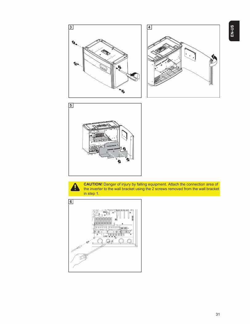
CAUTION! Danger of injury by falling equipment. Attach the connection area of the inverter to the wall bracket using the 2 screws removed from the wall bracket in step 1.
6
32
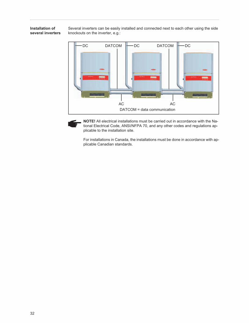
Installation of several inverters
Several inverters can be easily installed and connected next to each other using the side knockouts on the inverter, e.g.:
NOTE! All electrical installations must be carried out in accordance with the Na-tional Electrical Code, ANSI/NFPA 70, and any other codes and regulations ap-plicable to the installation site.
For installations in Canada, the installations must be done in accordance with ap-plicable Canadian standards.
CDCDCD
DATCOM = data communication
DATCOM DATCOM
AC AC
33
EN-U
S
Connecting the inverter to the public grid (AC)
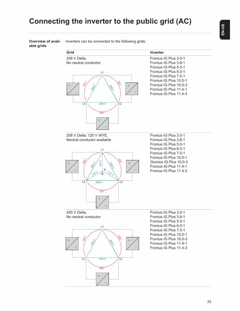
Overview of avail-able grids
Inverters can be connected to the following grids:
Grid Inverter208 V Delta,No neutral conductor
Fronius IG Plus 3.0-1Fronius IG Plus 3.8-1Fronius IG Plus 5.0-1Fronius IG Plus 6.0-1Fronius IG Plus 7.5-1Fronius IG Plus 10.0-1Fronius IG Plus 10.0-3Fronius IG Plus 11.4-1Fronius IG Plus 11.4-3
208 V Delta: 120 V WYE,Neutral conductor available
Fronius IG Plus 3.0-1Fronius IG Plus 3.8-1Fronius IG Plus 5.0-1Fronius IG Plus 6.0-1Fronius IG Plus 7.5-1Fronius IG Plus 10.0-1Gronius IG Plus 10.0-3Fronius IG Plus 11.4-1Fronius IG Plus 11.4-3
240 V Delta,No neutral conductor
Fronius IG Plus 3.0-1Fronius IG Plus 3.8-1Fronius IG Plus 5.0-1Fronius IG Plus 6.0-1Fronius IG Plus 7.5-1Fronius IG Plus 10.0-1Fronius IG Plus 10.0-3Fronius IG Plus 11.4-1Fronius IG Plus 11.4-3
120
° 120 °
120 °
208 V
208 V
208 V
L1
L2L3
=
~
=
~
=
~
120
V
120 V 120 V
120
° 120 °
120 °
208
V 208 V
208 V
L1
L2
N
L3
=
~
=
~
=
~
240 V240 V
240 V
120
° 120 °
120 °
L1
L2L3
=
~
=
~
=
~
34
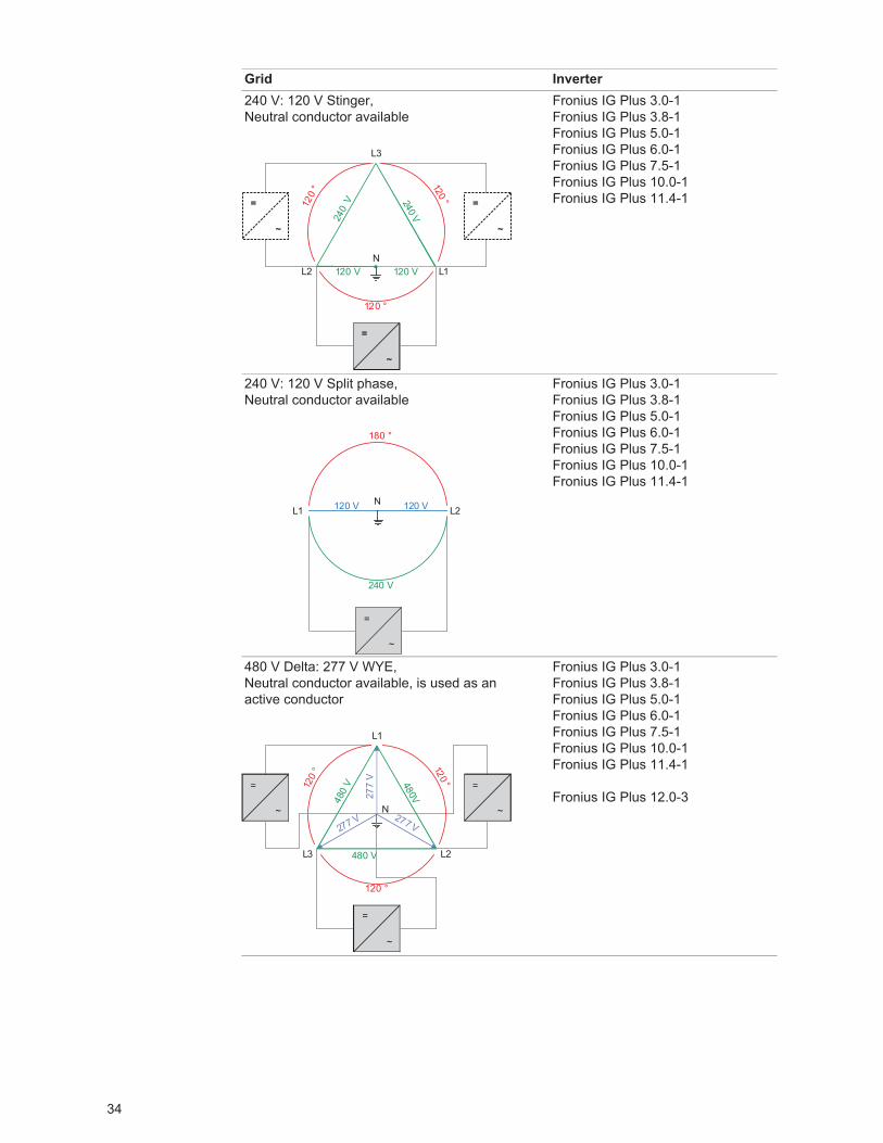
240 V: 120 V Stinger,Neutral conductor available
Fronius IG Plus 3.0-1Fronius IG Plus 3.8-1Fronius IG Plus 5.0-1Fronius IG Plus 6.0-1Fronius IG Plus 7.5-1Fronius IG Plus 10.0-1Fronius IG Plus 11.4-1
240 V: 120 V Split phase,Neutral conductor available
Fronius IG Plus 3.0-1Fronius IG Plus 3.8-1Fronius IG Plus 5.0-1Fronius IG Plus 6.0-1Fronius IG Plus 7.5-1Fronius IG Plus 10.0-1Fronius IG Plus 11.4-1
480 V Delta: 277 V WYE,Neutral conductor available, is used as an active conductor
Fronius IG Plus 3.0-1Fronius IG Plus 3.8-1Fronius IG Plus 5.0-1Fronius IG Plus 6.0-1Fronius IG Plus 7.5-1Fronius IG Plus 10.0-1Fronius IG Plus 11.4-1
Fronius IG Plus 12.0-3
Grid Inverter
240 V240
V120
° 120 °
120 °
120 V120 V
L3
L1N
L2
=
~
=
~
=
~
180 °
120 V 120 V
240 V
2L1LN
=
~
277
V
277 V 277 V
120
° 120 °
120 °
480
V 480V
480 V
L1
L2
N
L3
=
~
=
~
=
~
35
EN-U
S
Monitoring the Grid
Systems with more than one in-verter
For larger photovoltaic systems, it is possible to connect several inverters in parallel with-out any problems. To ensure symmetrical feeding, connect the inverters uniformly to all 3 phases.
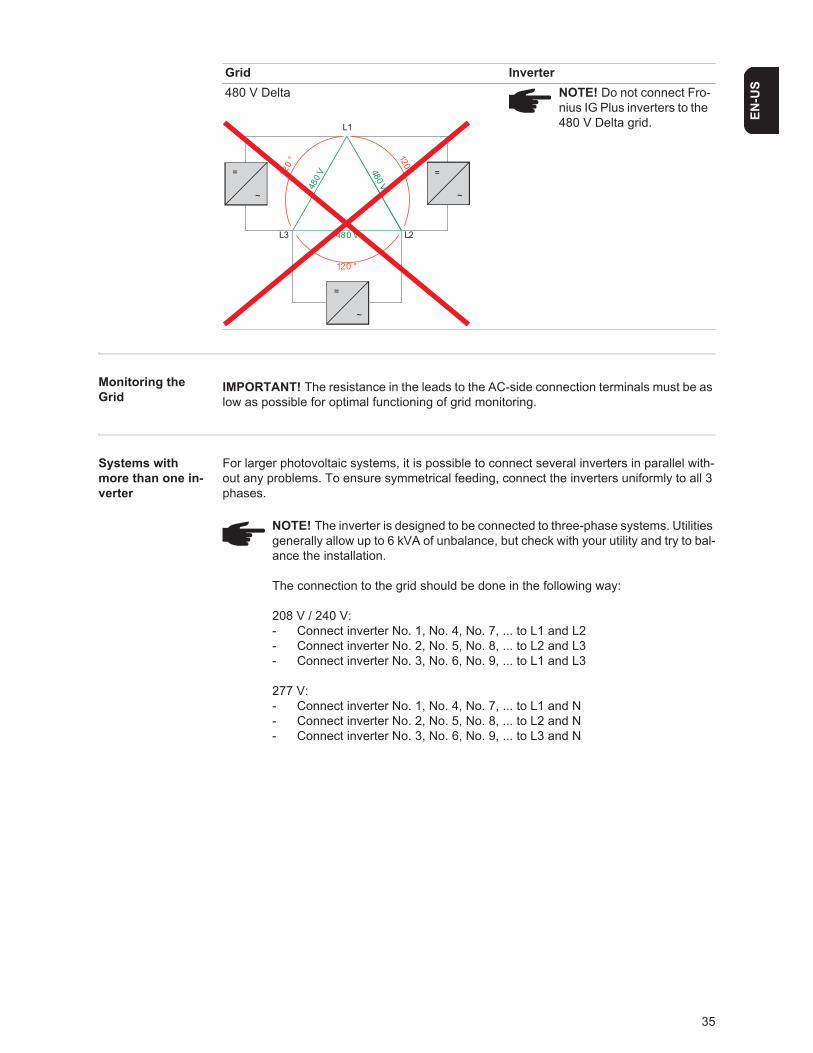
480 V Delta NOTE! Do not connect Fro-nius IG Plus inverters to the 480 V Delta grid.
Grid Inverter
480 V480 V
480 V
120
° 120 °
120 °
L1
L2L3
=
~
=
~
=
~
IMPORTANT! The resistance in the leads to the AC-side connection terminals must be as low as possible for optimal functioning of grid monitoring.
NOTE! The inverter is designed to be connected to three-phase systems. Utilities generally allow up to 6 kVA of unbalance, but check with your utility and try to bal-ance the installation.
The connection to the grid should be done in the following way:
208 V / 240 V:- Connect inverter No. 1, No. 4, No. 7, ... to L1 and L2- Connect inverter No. 2, No. 5, No. 8, ... to L2 and L3- Connect inverter No. 3, No. 6, No. 9, ... to L1 and L3
277 V:- Connect inverter No. 1, No. 4, No. 7, ... to L1 and N- Connect inverter No. 2, No. 5, No. 8, ... to L2 and N- Connect inverter No. 3, No. 6, No. 9, ... to L3 and N
36
AC-side terminals and grounding terminals
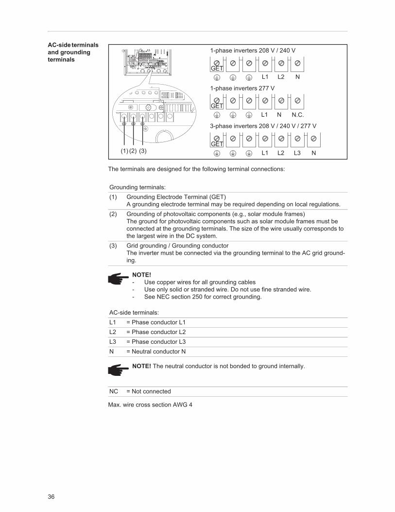
The terminals are designed for the following terminal connections:
Max. wire cross section AWG 4
Grounding terminals:(1) Grounding Electrode Terminal (GET)
A grounding electrode terminal may be required depending on local regulations.(2) Grounding of photovoltaic components (e.g., solar module frames)
The ground for photovoltaic components such as solar module frames must be connected at the grounding terminals. The size of the wire usually corresponds to the largest wire in the DC system.
(3) Grid grounding / Grounding conductorThe inverter must be connected via the grounding terminal to the AC grid ground-ing.
NOTE!- Use copper wires for all grounding cables- Use only solid or stranded wire. Do not use fine stranded wire.- See NEC section 250 for correct grounding.
AC-side terminals:L1 = Phase conductor L1L2 = Phase conductor L2L3 = Phase conductor L3N = Neutral conductor N
NOTE! The neutral conductor is not bonded to ground internally.
NC = Not connected
(1) (2) (3)
1-phase inverters 208 V / 240 V
1-phase inverters 277 V
3-phase inverters 208 V / 240 V / 277 V
L1 L2 N
N.C.L1 N
L3L1 L2 N
GET
GET
GET
37
EN-U
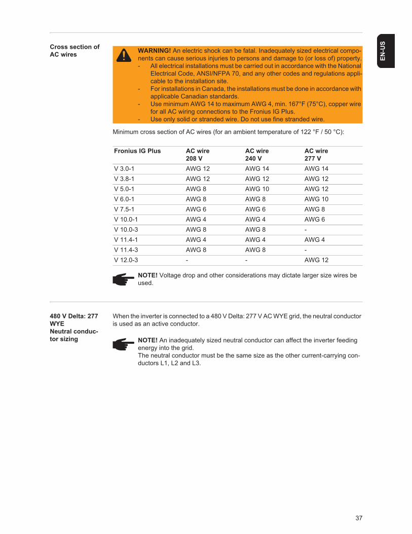
SCross section of AC wires
Minimum cross section of AC wires (for an ambient temperature of 122 °F / 50 °C):
480 V Delta: 277 WYE Neutral conduc-tor sizing
When the inverter is connected to a 480 V Delta: 277 V AC WYE grid, the neutral conductor is used as an active conductor.
WARNING! An electric shock can be fatal. Inadequately sized electrical compo-nents can cause serious injuries to persons and damage to (or loss of) property.- All electrical installations must be carried out in accordance with the National
Electrical Code, ANSI/NFPA 70, and any other codes and regulations appli-cable to the installation site.
- For installations in Canada, the installations must be done in accordance with applicable Canadian standards.
- Use minimum AWG 14 to maximum AWG 4, min. 167°F (75°C), copper wire for all AC wiring connections to the Fronius IG Plus.
- Use only solid or stranded wire. Do not use fine stranded wire.
Fronius IG Plus AC wire208 V
AC wire240 V
AC wire277 V
V 3.0-1 AWG 12 AWG 14 AWG 14V 3.8-1 AWG 12 AWG 12 AWG 12V 5.0-1 AWG 8 AWG 10 AWG 12V 6.0-1 AWG 8 AWG 8 AWG 10V 7.5-1 AWG 6 AWG 6 AWG 8V 10.0-1 AWG 4 AWG 4 AWG 6V 10.0-3 AWG 8 AWG 8 -V 11.4-1 AWG 4 AWG 4 AWG 4V 11.4-3 AWG 8 AWG 8 -V 12.0-3 - - AWG 12
NOTE! Voltage drop and other considerations may dictate larger size wires be used.
NOTE! An inadequately sized neutral conductor can affect the inverter feeding energy into the grid.The neutral conductor must be the same size as the other current-carrying con-ductors L1, L2 and L3.
38
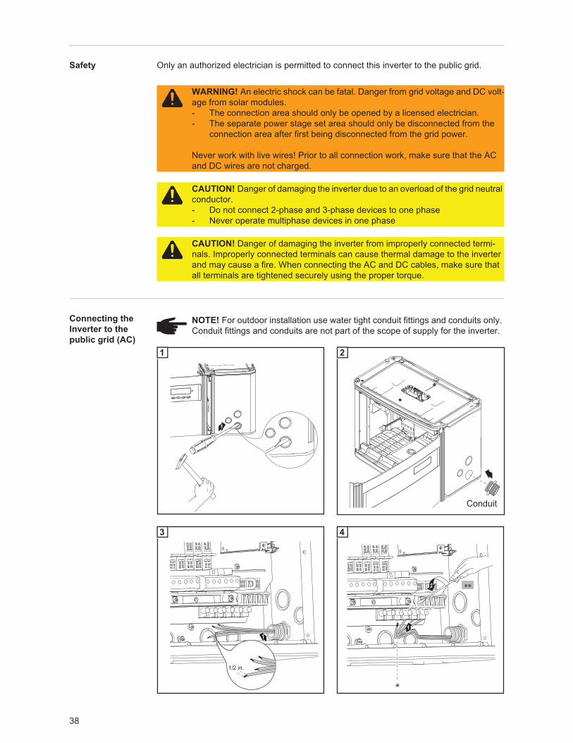
Safety Only an authorized electrician is permitted to connect this inverter to the public grid.
Connecting the Inverter to the public grid (AC)
WARNING! An electric shock can be fatal. Danger from grid voltage and DC volt-age from solar modules.- The connection area should only be opened by a licensed electrician.- The separate power stage set area should only be disconnected from the
connection area after first being disconnected from the grid power.
Never work with live wires! Prior to all connection work, make sure that the AC and DC wires are not charged.
CAUTION! Danger of damaging the inverter due to an overload of the grid neutral conductor.- Do not connect 2-phase and 3-phase devices to one phase- Never operate multiphase devices in one phase
CAUTION! Danger of damaging the inverter from improperly connected termi-nals. Improperly connected terminals can cause thermal damage to the inverter and may cause a fire. When connecting the AC and DC cables, make sure that all terminals are tightened securely using the proper torque.
NOTE! For outdoor installation use water tight conduit fittings and conduits only. Conduit fittings and conduits are not part of the scope of supply for the inverter.
1
1
Conduit
2
1/2 in.
1
3
2
1
*
**
4
39
EN-U
S
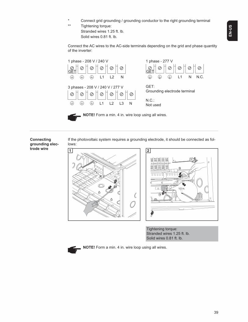
* Connect grid grounding / grounding conductor to the right grounding terminal** Tightening torque:
Stranded wires 1.25 ft. lb.Solid wires 0.81 ft. lb.
Connect the AC wires to the AC-side terminals depending on the grid and phase quantity of the inverter:
GET:Grounding electrode terminal
N.C.:Not used
Connecting grounding elec-trode wire
If the photovoltaic system requires a grounding electrode, it should be connected as fol-lows:
L1 L2 NGET
1 phase - 208 V / 240 V 1 phase - 277 V
GETL1 N N.C.
3 phases - 208 V / 240 V / 277 V
L1 L2 NL3
NOTE! Form a min. 4 in. wire loop using all wires.
1
2
1
4
3
1
1/2 in.
2
2
Tightening torque:Stranded wires 1.25 ft. lb.Solid wires 0.81 ft. lb.
NOTE! Form a min. 4 in. wire loop using all wires.
40
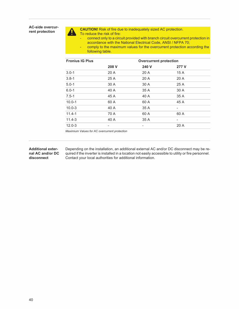
AC-side overcur-rent protection
Maximium Values for AC overcurrent protection
Additional exter-nal AC and/or DC disconnect
Depending on the installation, an additional external AC and/or DC disconnect may be re-quired if the inverter is installed in a location not easily accessible to utility or fire personnel. Contact your local authorities for additional information.
CAUTION! Risk of fire due to inadequately sized AC protection.To reduce the risk of fire:- connect only to a circuit provided with branch circuit overcurrent protection in
accordance with the National Electrical Code, ANSI / NFPA 70;- comply to the maximum values for the overcurrent protection according the
following table.
Fronius IG Plus Overcurrent protection208 V 240 V 277 V
3.0-1 20 A 20 A 15 A3.8-1 25 A 20 A 20 A5.0-1 30 A 30 A 25 A6.0-1 40 A 35 A 30 A7.5-1 45 A 40 A 35 A10.0-1 60 A 60 A 45 A10.0-3 40 A 35 A -11.4-1 70 A 60 A 60 A11.4-3 40 A 35 A -12.0-3 - - 20 A
41
EN-U
S
Connecting solar module strings to the inverter (DC)
General informa-tion about solar modules
In order to select suitable solar modules and get the most efficient use out of the inverter, please note the following points:- The open circuit voltage of the solar modules increases as the temperature decreases
(assuming constant irradiance). The open circuit voltage should never rise above 600 V regardless of temperature and an irradiance of 1000 W/m². If the open circuit voltage exceeds 600 volts, the inverter may be damaged, and all warranty rights will become null and void.
- More exact data for sizing the solar array for the particular location can be obtained using calculation tools such as the Fronius Configuration Tool (available at http://www.fronius-usa.com).
- See NEC table 690.7 for the appropriate code-related voltage adjustment factor for crystalline silicon modules, or use the manufacturer’s specified voltage coefficient.
Safety
DC terminals
WARNING! An electric shock can be fatal. Danger due to grid voltage and DC voltage from solar modules.- The connection area should only be opened by a licensed electrician.- The separate power stage set area should only be disconnected from the
connection area after first being disconnected from the grid power.- The separate power stage set area should only be opened by Fronius-trained
service personnel.
Never work with live wires! Prior to all connection work, make sure that the AC and DC wires are not charged.
The DC main switch is only used to switch off power to the power stage set. When the DC main switch is turned off, the connection area is still energized.
CAUTION! Danger of damaging the inverter from improperly connected termi-nals. Improperly connected terminals can cause thermal damage to the inverter and may cause a fire. When connecting the AC and DC cables, make sure that all terminals are tightened securely using the proper torque.
DC+ DC-
42
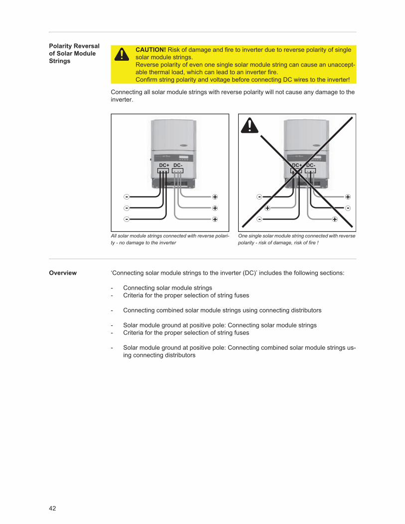
Polarity Reversal of Solar Module Strings
Connecting all solar module strings with reverse polarity will not cause any damage to the inverter.
All solar module strings connected with reverse polari-ty - no damage to the inverter
One single solar module string connected with reverse polarity - risk of damage, risk of fire !
Overview ‘Connecting solar module strings to the inverter (DC)’ includes the following sections:
- Connecting solar module strings- Criteria for the proper selection of string fuses
- Connecting combined solar module strings using connecting distributors
- Solar module ground at positive pole: Connecting solar module strings- Criteria for the proper selection of string fuses
- Solar module ground at positive pole: Connecting combined solar module strings us-ing connecting distributors
CAUTION! Risk of damage and fire to inverter due to reverse polarity of single solar module strings.Reverse polarity of even one single solar module string can cause an unaccept-able thermal load, which can lead to an inverter fire.Confirm string polarity and voltage before connecting DC wires to the inverter!
DC+ DC-
+---
++
DC+ DC-
+--
-+
+
43
EN-U
S
Connecting Solar Module Strings
Solar module ground
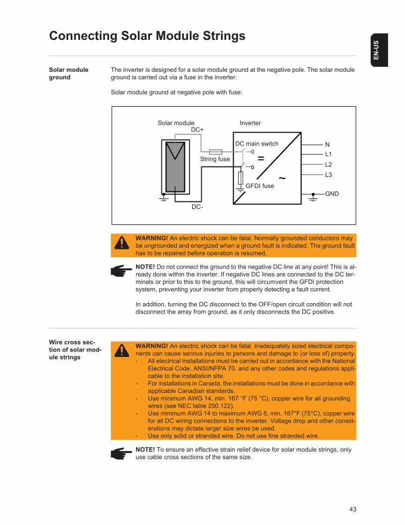
The inverter is designed for a solar module ground at the negative pole. The solar module ground is carried out via a fuse in the inverter.
Solar module ground at negative pole with fuse:
Wire cross sec-tion of solar mod-ule strings
WARNING! An electric shock can be fatal. Normally grounded conductors may be ungrounded and energized when a ground fault is indicated. The ground fault has to be repaired before operation is resumed.
NOTE! Do not connect the ground to the negative DC line at any point! This is al-ready done within the inverter. If negative DC lines are connected to the DC ter-minals or prior to this to the ground, this will circumvent the GFDI protection system, preventing your inverter from properly detecting a fault current.
In addition, turning the DC disconnect to the OFF/open circuit condition will not disconnect the array from ground, as it only disconnects the DC positive.
~=
DC+
DC-
Inverter
NL1
GND
Solar module
DC main switch
L3L2
GFDI fuse
String fuse
WARNING! An electric shock can be fatal. Inadequately sized electrical compo-nents can cause serious injuries to persons and damage to (or loss of) property.- All electrical installations must be carried out in accordance with the National
Electrical Code, ANSI/NFPA 70, and any other codes and regulations appli-cable to the installation site.
- For installations in Canada, the installations must be done in accordance with applicable Canadian standards.
- Use minimum AWG 14, min. 167 °F (75 °C), copper wire for all grounding wires (see NEC table 250.122).
- Use minimum AWG 14 to maximum AWG 6, min. 167°F (75°C), copper wire for all DC wiring connections to the inverter. Voltage drop and other consid-erations may dictate larger size wires be used.
- Use only solid or stranded wire. Do not use fine stranded wire.
NOTE! To ensure an effective strain relief device for solar module strings, only use cable cross sections of the same size.
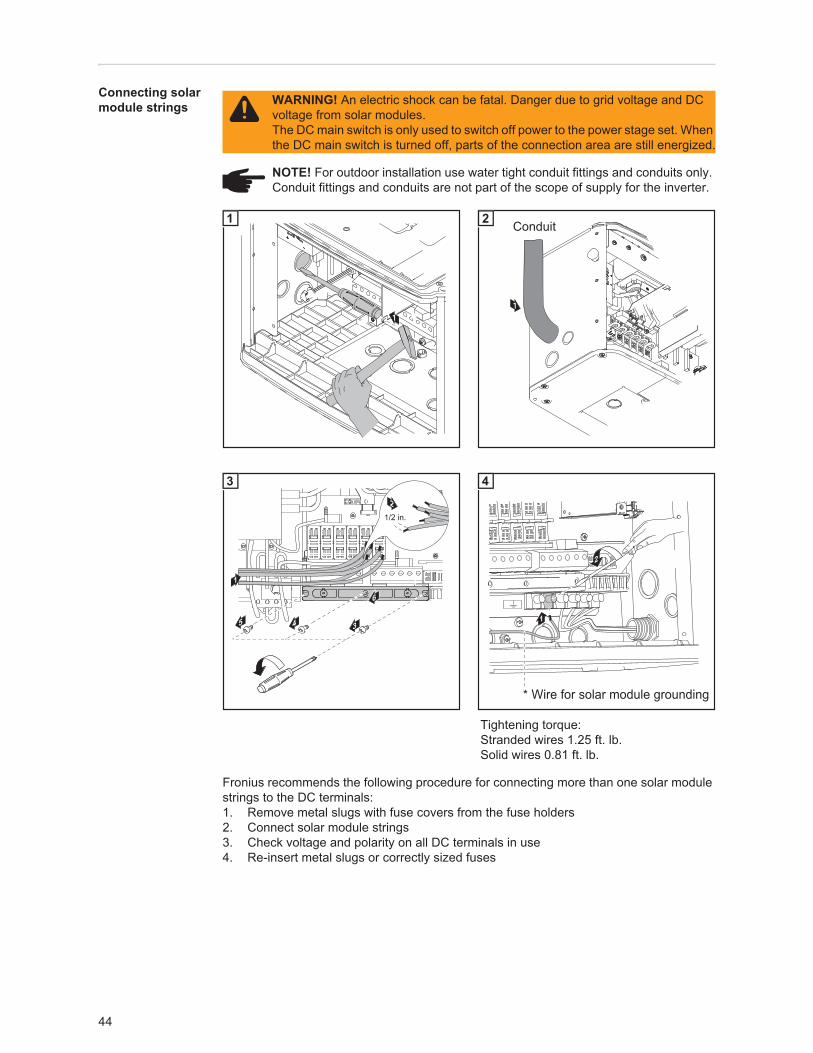
44
Connecting solar module strings
Fronius recommends the following procedure for connecting more than one solar module strings to the DC terminals:1. Remove metal slugs with fuse covers from the fuse holders2. Connect solar module strings3. Check voltage and polarity on all DC terminals in use4. Re-insert metal slugs or correctly sized fuses
WARNING! An electric shock can be fatal. Danger due to grid voltage and DC voltage from solar modules.The DC main switch is only used to switch off power to the power stage set. When the DC main switch is turned off, parts of the connection area are still energized.
NOTE! For outdoor installation use water tight conduit fittings and conduits only. Conduit fittings and conduits are not part of the scope of supply for the inverter.
1
1
1
Conduit2
Tightening torque:Stranded wires 1.25 ft. lb.Solid wires 0.81 ft. lb.
1
3
1/2 in.
2
4
5 4
6
3
2
1
* Wire for solar module grounding
4
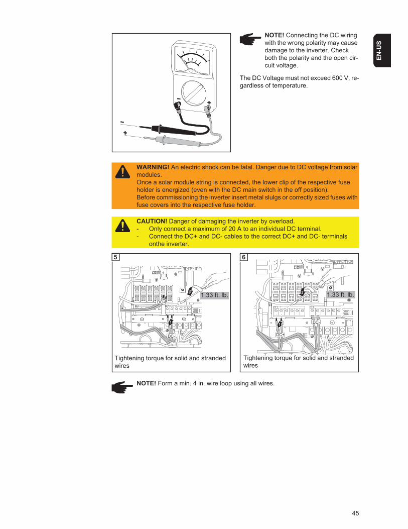
45
EN-U
S
The DC Voltage must not exceed 600 V, re-gardless of temperature.
NOTE! Connecting the DC wiring with the wrong polarity may cause damage to the inverter. Check both the polarity and the open cir-cuit voltage.
WARNING! An electric shock can be fatal. Danger due to DC voltage from solar modules.Once a solar module string is connected, the lower clip of the respective fuse holder is energized (even with the DC main switch in the off position).Before commissioning the inverter insert metal slulgs or correctly sized fuses with fuse covers into the respective fuse holder.
CAUTION! Danger of damaging the inverter by overload.- Only connect a maximum of 20 A to an individual DC terminal.- Connect the DC+ and DC- cables to the correct DC+ and DC- terminals
onthe inverter.
DC+
2
DC-
1
DC+1.33 ft. lb.
Tightening torque for solid and strandedwires
DC - DC +
5
3
2
DC-1
DC+
1.33 ft. lb.
Tightening torque for solid and strandedwires
DC - DC +
6
NOTE! Form a min. 4 in. wire loop using all wires.
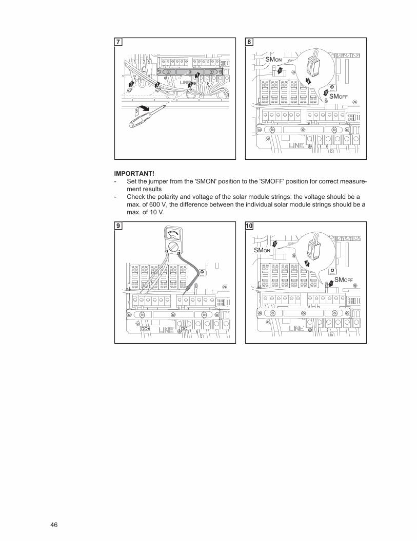
46
IMPORTANT!- Set the jumper from the 'SMON' position to the 'SMOFF' position for correct measure-
ment results- Check the polarity and voltage of the solar module strings: the voltage should be a
max. of 600 V, the difference between the individual solar module strings should be a max. of 10 V.
4
1
2 22
3
7
3
1
2
SMON
SMOFF
8
DC+ DC-
9
3
1
2
SMON
SMOFF
10
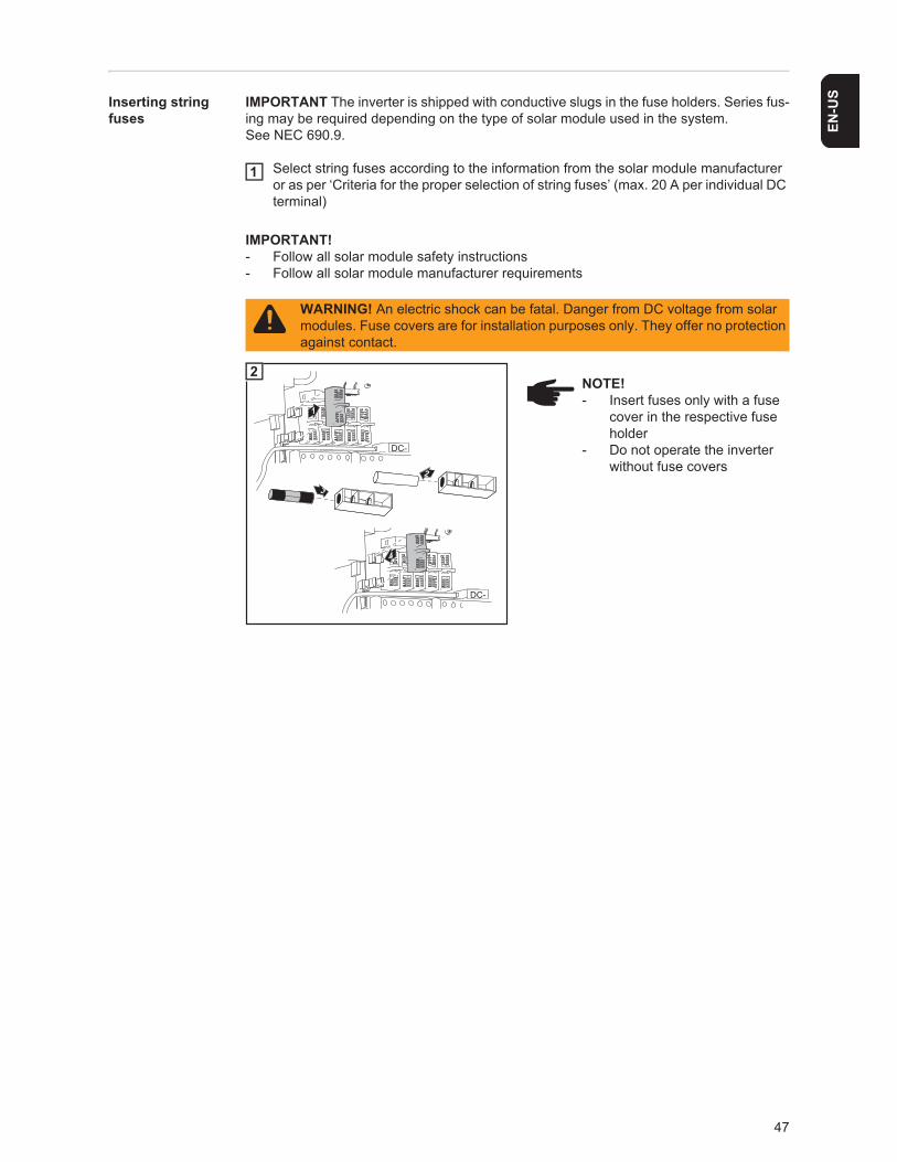
47
EN-U
SInserting string fuses
IMPORTANT The inverter is shipped with conductive slugs in the fuse holders. Series fus-ing may be required depending on the type of solar module used in the system.See NEC 690.9.
Select string fuses according to the information from the solar module manufacturer or as per ‘Criteria for the proper selection of string fuses’ (max. 20 A per individual DC terminal)
IMPORTANT!- Follow all solar module safety instructions- Follow all solar module manufacturer requirements
WARNING! An electric shock can be fatal. Danger from DC voltage from solar modules. Fuse covers are for installation purposes only. They offer no protection against contact.
1
1
4
2
3
DC-
DC-
2NOTE!- Insert fuses only with a fuse
cover in the respective fuse holder
- Do not operate the inverter without fuse covers
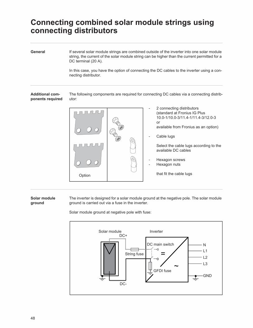
48
Connecting combined solar module strings using connecting distributors
General If several solar module strings are combined outside of the inverter into one solar module string, the current of the solar module string can be higher than the current permitted for a DC terminal (20 A).
In this case, you have the option of connecting the DC cables to the inverter using a con-necting distributor.
Additional com-ponents required
The following components are required for connecting DC cables via a connecting distrib-utor:
- 2 connecting distributors (standard at Fronius IG Plus10.0-1/10.0-3/11.4-1/11.4-3/12.0-3oravailable from Fronius as an option)
- Cable lugs
Select the cable lugs according to the available DC cables
- Hexagon screws- Hexagon nuts
that fit the cable lugs
Solar module ground
The inverter is designed for a solar module ground at the negative pole. The solar module ground is carried out via a fuse in the inverter.
Solar module ground at negative pole with fuse:
Option
~=
DC+
DC-
Inverter
NL1
GND
Solar module
DC main switch
L3L2
GFDI fuse
String fuse
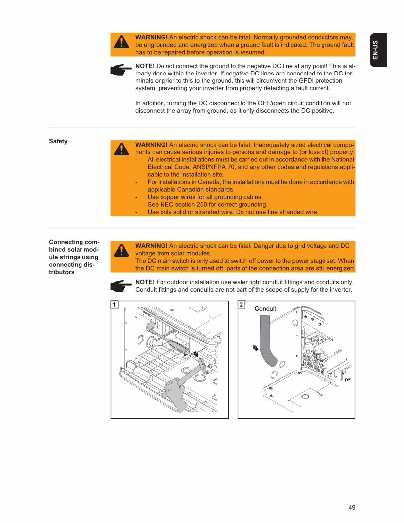
49
EN-U
S
Safety
Connecting com-bined solar mod-ule strings using connecting dis-tributors
WARNING! An electric shock can be fatal. Normally grounded conductors may be ungrounded and energized when a ground fault is indicated. The ground fault has to be repaired before operation is resumed.
NOTE! Do not connect the ground to the negative DC line at any point! This is al-ready done within the inverter. If negative DC lines are connected to the DC ter-minals or prior to this to the ground, this will circumvent the GFDI protection system, preventing your inverter from properly detecting a fault current.
In addition, turning the DC disconnect to the OFF/open circuit condition will not disconnect the array from ground, as it only disconnects the DC positive.
WARNING! An electric shock can be fatal. Inadequately sized electrical compo-nents can cause serious injuries to persons and damage to (or loss of) property.- All electrical installations must be carried out in accordance with the National
Electrical Code, ANSI/NFPA 70, and any other codes and regulations appli-cable to the installation site.
- For installations in Canada, the installations must be done in accordance with applicable Canadian standards.
- Use copper wires for all grounding cables.- See NEC section 250 for correct grounding.- Use only solid or stranded wire. Do not use fine stranded wire.
WARNING! An electric shock can be fatal. Danger due to grid voltage and DC voltage from solar modules.The DC main switch is only used to switch off power to the power stage set. When the DC main switch is turned off, parts of the connection area are still energized.
NOTE! For outdoor installation use water tight conduit fittings and conduits only. Conduit fittings and conduits are not part of the scope of supply for the inverter.
1
1
1
Conduit2
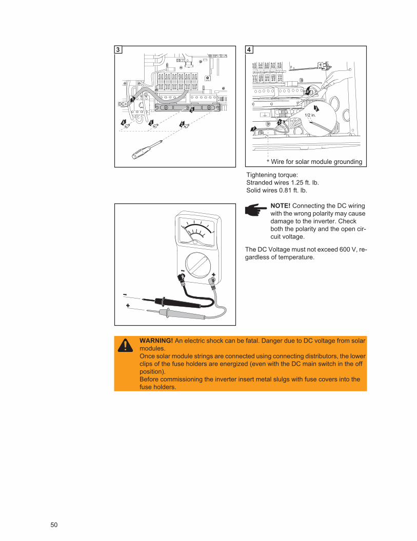
50
The DC Voltage must not exceed 600 V, re-gardless of temperature.
Tightening torque:Stranded wires 1.25 ft. lb.Solid wires 0.81 ft. lb.
24 3
5
1DC+
3
4
1/2 in.
2
13
* Wire for solar module grounding
4
NOTE! Connecting the DC wiring with the wrong polarity may cause damage to the inverter. Check both the polarity and the open cir-cuit voltage.
WARNING! An electric shock can be fatal. Danger due to DC voltage from solar modules.Once solar module strings are connected using connecting distributors, the lower clips of the fuse holders are energized (even with the DC main switch in the off position).Before commissioning the inverter insert metal slulgs with fuse covers into the fuse holders.
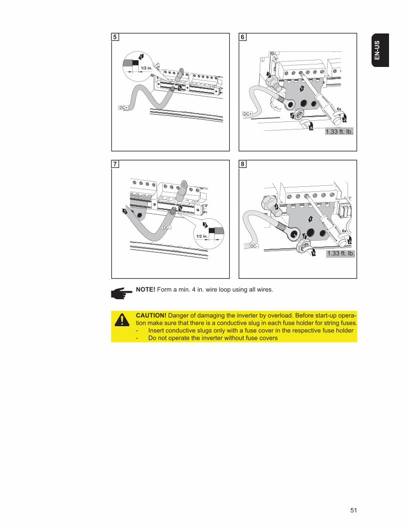
51
EN-U
S
2
1/2 in.
1
DC+
5
3
1
6x
23
4
DC+
1.33 ft. lb.
6
3
1/2 in.
2
1
DC-
7
2
3
6x
4
3
1
DC-
1.33 ft. lb.
8
NOTE! Form a min. 4 in. wire loop using all wires.
CAUTION! Danger of damaging the inverter by overload. Before start-up opera-tion make sure that there is a conductive slug in each fuse holder for string fuses.- Insert conductive slugs only with a fuse cover in the respective fuse holder- Do not operate the inverter without fuse covers
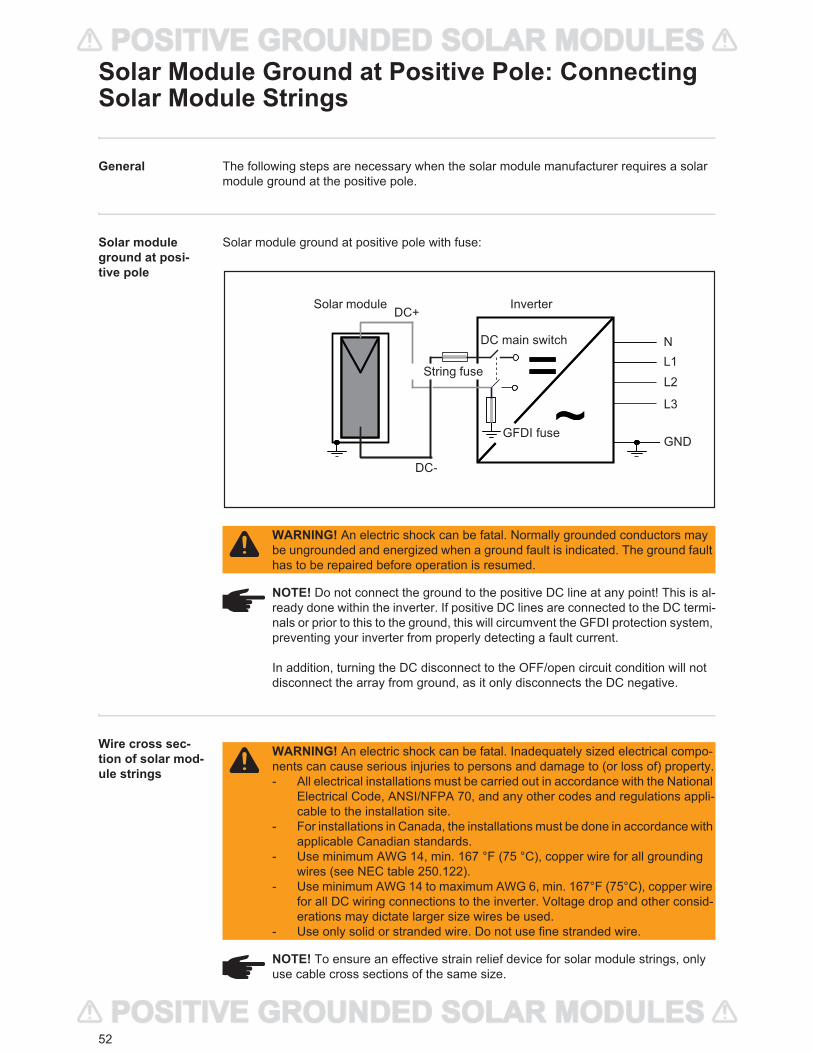
52
Solar Module Ground at Positive Pole: Connecting Solar Module Strings
General The following steps are necessary when the solar module manufacturer requires a solar module ground at the positive pole.
Solar module ground at posi-tive pole
Solar module ground at positive pole with fuse:
Wire cross sec-tion of solar mod-ule strings
WARNING! An electric shock can be fatal. Normally grounded conductors may be ungrounded and energized when a ground fault is indicated. The ground fault has to be repaired before operation is resumed.
NOTE! Do not connect the ground to the positive DC line at any point! This is al-ready done within the inverter. If positive DC lines are connected to the DC termi-nals or prior to this to the ground, this will circumvent the GFDI protection system, preventing your inverter from properly detecting a fault current.
In addition, turning the DC disconnect to the OFF/open circuit condition will not disconnect the array from ground, as it only disconnects the DC negative.
=~
=~
DC+
DC-
Inverter
L1N
GND
Solar module
DC main switch
GFDI fuse
String fuseL2
L3
WARNING! An electric shock can be fatal. Inadequately sized electrical compo-nents can cause serious injuries to persons and damage to (or loss of) property.- All electrical installations must be carried out in accordance with the National
Electrical Code, ANSI/NFPA 70, and any other codes and regulations appli-cable to the installation site.
- For installations in Canada, the installations must be done in accordance with applicable Canadian standards.
- Use minimum AWG 14, min. 167 °F (75 °C), copper wire for all grounding wires (see NEC table 250.122).
- Use minimum AWG 14 to maximum AWG 6, min. 167°F (75°C), copper wire for all DC wiring connections to the inverter. Voltage drop and other consid-erations may dictate larger size wires be used.
- Use only solid or stranded wire. Do not use fine stranded wire.
NOTE! To ensure an effective strain relief device for solar module strings, only use cable cross sections of the same size.
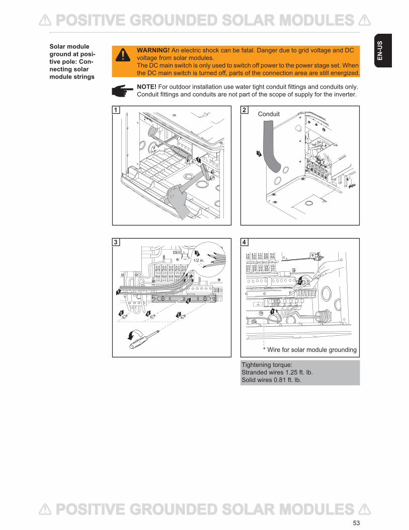
53
EN-U
SSolar module ground at posi-tive pole: Con-necting solar module strings
WARNING! An electric shock can be fatal. Danger due to grid voltage and DC voltage from solar modules.The DC main switch is only used to switch off power to the power stage set. When the DC main switch is turned off, parts of the connection area are still energized.
NOTE! For outdoor installation use water tight conduit fittings and conduits only. Conduit fittings and conduits are not part of the scope of supply for the inverter.
1
1
1
Conduit2
Tightening torque:Stranded wires 1.25 ft. lb.Solid wires 0.81 ft. lb.
1
3
1/2 in.
2
4
5 4
6
3
2
1
* Wire for solar module grounding
4
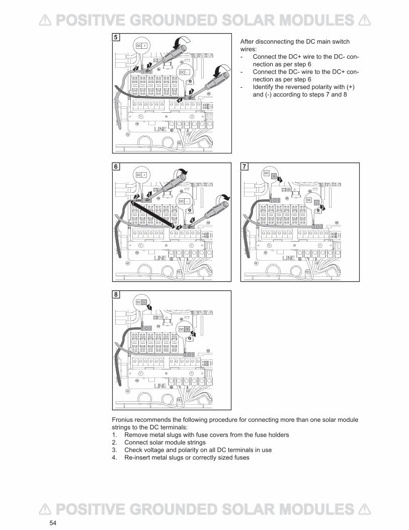
54
After disconnecting the DC main switch wires:- Connect the DC+ wire to the DC- con-
nection as per step 6- Connect the DC- wire to the DC+ con-
nection as per step 6- Identify the reversed polarity with (+)
and (-) according to steps 7 and 8
Fronius recommends the following procedure for connecting more than one solar module strings to the DC terminals:1. Remove metal slugs with fuse covers from the fuse holders2. Connect solar module strings3. Check voltage and polarity on all DC terminals in use4. Re-insert metal slugs or correctly sized fuses
3
2
4
1
DC
DC
+
-
5
DC
DC
+
-
45
32
1
1
6DC
DC
+
-
1
2
7
DC
DC
-
+
1
2
8
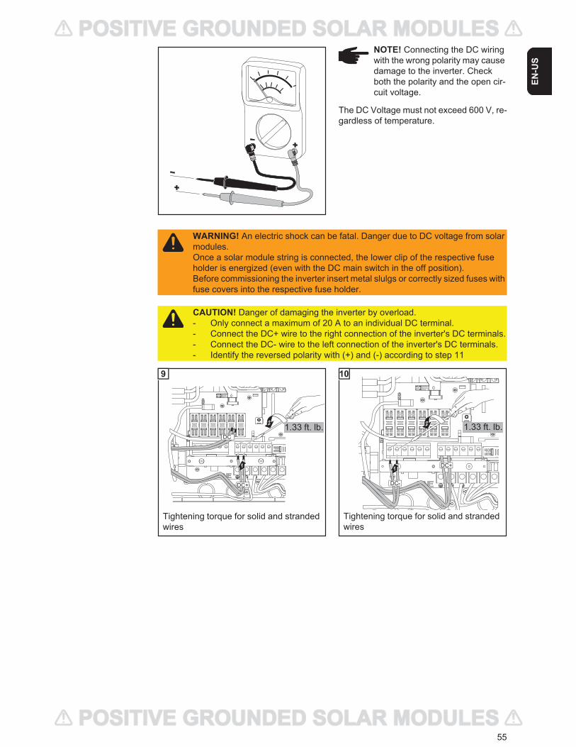
55
EN-U
S
The DC Voltage must not exceed 600 V, re-gardless of temperature.
NOTE! Connecting the DC wiring with the wrong polarity may cause damage to the inverter. Check both the polarity and the open cir-cuit voltage.
WARNING! An electric shock can be fatal. Danger due to DC voltage from solar modules.Once a solar module string is connected, the lower clip of the respective fuse holder is energized (even with the DC main switch in the off position).Before commissioning the inverter insert metal slulgs or correctly sized fuses with fuse covers into the respective fuse holder.
CAUTION! Danger of damaging the inverter by overload. - Only connect a maximum of 20 A to an individual DC terminal.- Connect the DC+ wire to the right connection of the inverter's DC terminals.- Connect the DC- wire to the left connection of the inverter's DC terminals.- Identify the reversed polarity with (+) and (-) according to step 11
1.33 ft. lb.
Tightening torque for solid and strandedwires
9
1.33 ft. lb.
Tightening torque for solid and strandedwires
10
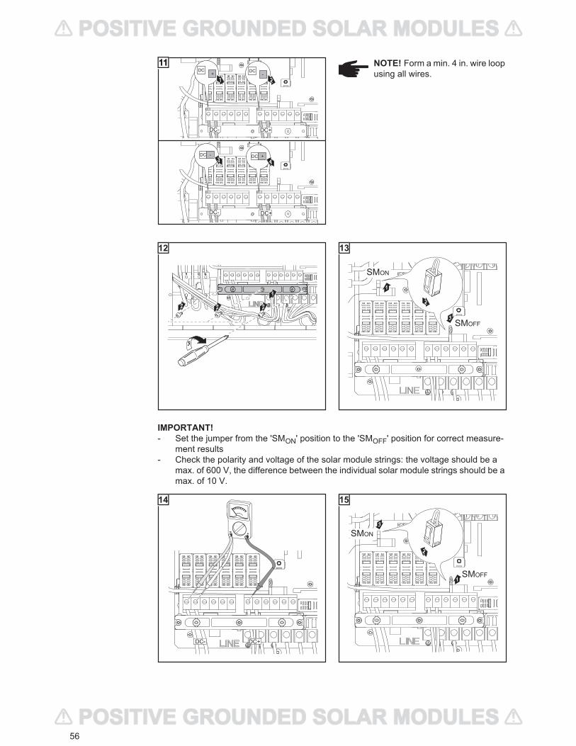
56
DC+
DC + DC -
DC+ DC
DC-
DC+DC-
DC - DC +
DC - DC
-
+
1
3
2
4
1111 NOTE! Form a min. 4 in. wire loop using all wires.
4
1
2 22
3
12
3
1
2
SMON
SMOFF
13
IMPORTANT!- Set the jumper from the 'SMON' position to the 'SMOFF' position for correct measure-
ment results- Check the polarity and voltage of the solar module strings: the voltage should be a
max. of 600 V, the difference between the individual solar module strings should be a max. of 10 V.
14
3
1
2
SMON
SMOFF
15

57
EN-U
SInserting string fuses
IMPORTANT The inverter is shipped with conductive slugs in the fuse holders. Series fus-ing may be required depending on the type of solar module used in the system.See NEC 690.9.
Select string fuses according to the information from the solar module manufacturer or as per ‘Criteria for the proper selection of string fuses’ (max. 20 A per individual DC terminal)
IMPORTANT!- Follow all solar module safety instructions- Follow all solar module manufacturer requirements
WARNING! An electric shock can be fatal. Danger from DC voltage from solar modules. Fuse covers are for installation purposes only. They offer no protection against contact.
1
1
4
2
3
DC-
DC-
2NOTE!- Insert fuses only with a fuse
cover in the respective fuse holder
- Do not operate the inverter without fuse covers
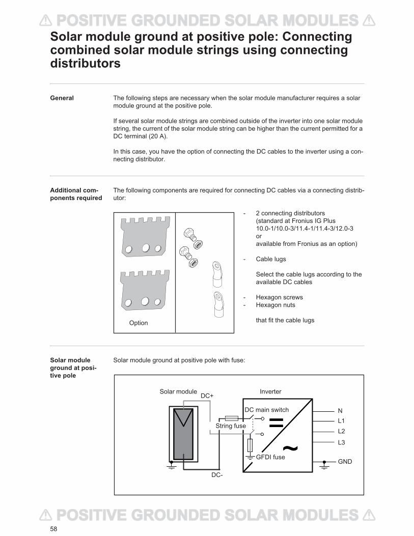
58
Solar module ground at positive pole: Connecting combined solar module strings using connecting distributors
General The following steps are necessary when the solar module manufacturer requires a solar module ground at the positive pole.
If several solar module strings are combined outside of the inverter into one solar module string, the current of the solar module string can be higher than the current permitted for a DC terminal (20 A).
In this case, you have the option of connecting the DC cables to the inverter using a con-necting distributor.
Additional com-ponents required
The following components are required for connecting DC cables via a connecting distrib-utor:
- 2 connecting distributors (standard at Fronius IG Plus10.0-1/10.0-3/11.4-1/11.4-3/12.0-3oravailable from Fronius as an option)
- Cable lugs
Select the cable lugs according to the available DC cables
- Hexagon screws- Hexagon nuts
that fit the cable lugs
Solar module ground at posi-tive pole
Solar module ground at positive pole with fuse:
Option
=~
=~
DC+
DC-
Inverter
L1N
GND
Solar module
DC main switch
GFDI fuse
String fuseL2
L3
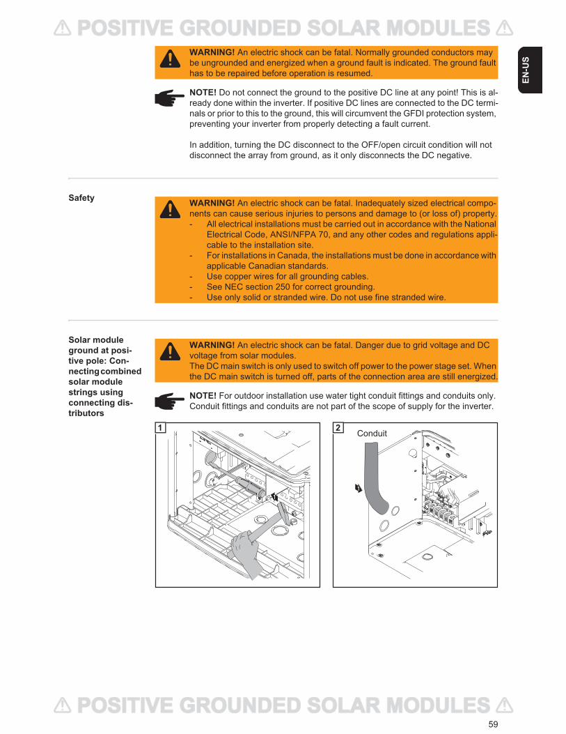
59
EN-U
S
Safety
Solar module ground at posi-tive pole: Con-necting combined solar module strings using connecting dis-tributors
WARNING! An electric shock can be fatal. Normally grounded conductors may be ungrounded and energized when a ground fault is indicated. The ground fault has to be repaired before operation is resumed.
NOTE! Do not connect the ground to the positive DC line at any point! This is al-ready done within the inverter. If positive DC lines are connected to the DC termi-nals or prior to this to the ground, this will circumvent the GFDI protection system, preventing your inverter from properly detecting a fault current.
In addition, turning the DC disconnect to the OFF/open circuit condition will not disconnect the array from ground, as it only disconnects the DC negative.
WARNING! An electric shock can be fatal. Inadequately sized electrical compo-nents can cause serious injuries to persons and damage to (or loss of) property.- All electrical installations must be carried out in accordance with the National
Electrical Code, ANSI/NFPA 70, and any other codes and regulations appli-cable to the installation site.
- For installations in Canada, the installations must be done in accordance with applicable Canadian standards.
- Use copper wires for all grounding cables.- See NEC section 250 for correct grounding.- Use only solid or stranded wire. Do not use fine stranded wire.
WARNING! An electric shock can be fatal. Danger due to grid voltage and DC voltage from solar modules.The DC main switch is only used to switch off power to the power stage set. When the DC main switch is turned off, parts of the connection area are still energized.
NOTE! For outdoor installation use water tight conduit fittings and conduits only. Conduit fittings and conduits are not part of the scope of supply for the inverter.
1
1
1
Conduit2
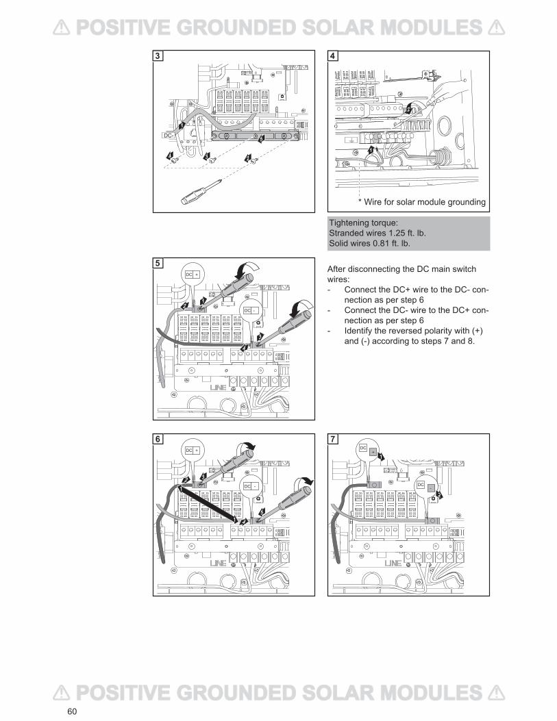
60
After disconnecting the DC main switch wires:- Connect the DC+ wire to the DC- con-
nection as per step 6- Connect the DC- wire to the DC+ con-
nection as per step 6- Identify the reversed polarity with (+)
and (-) according to steps 7 and 8.
Tightening torque:Stranded wires 1.25 ft. lb.Solid wires 0.81 ft. lb.
24 3
5
1DC-
3
2
1
* Wire for solar module grounding
4
3
2
4
1
DC
DC
+
-
5
DC
DC
+
-
45
32
1
1
6DC
DC
+
-
1
2
7
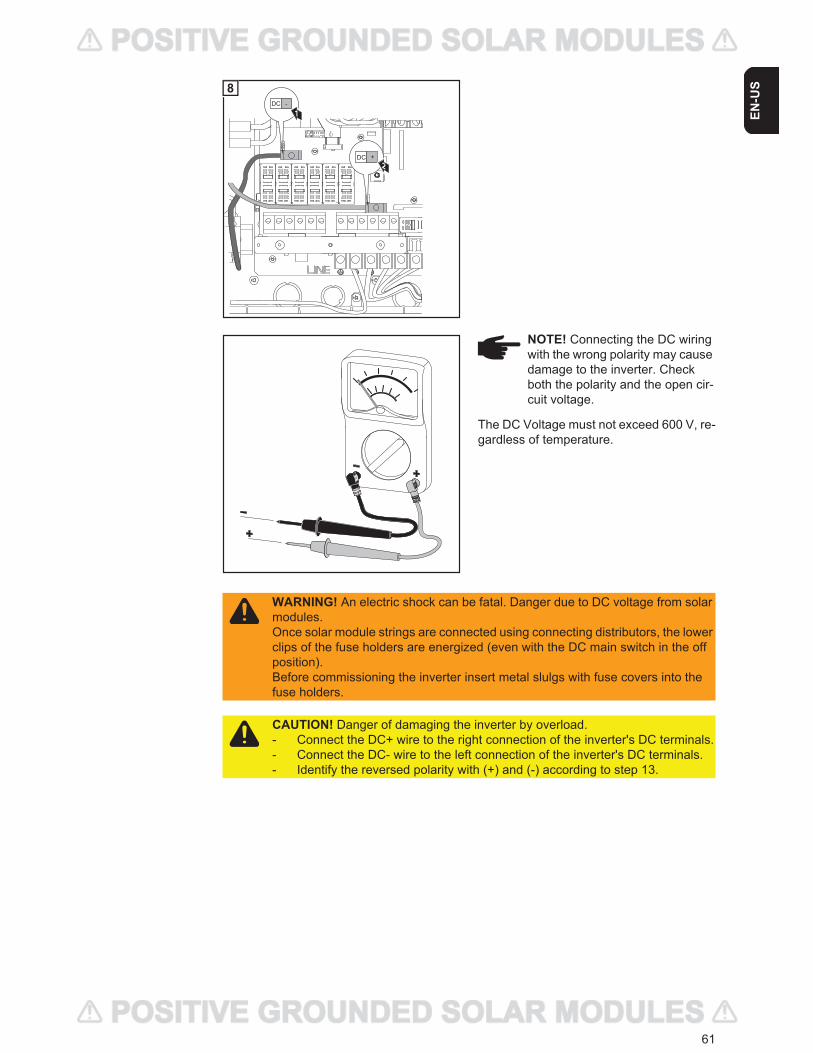
61
EN-U
S
The DC Voltage must not exceed 600 V, re-gardless of temperature.
DC
DC
-
+
1
2
8
NOTE! Connecting the DC wiring with the wrong polarity may cause damage to the inverter. Check both the polarity and the open cir-cuit voltage.
WARNING! An electric shock can be fatal. Danger due to DC voltage from solar modules.Once solar module strings are connected using connecting distributors, the lower clips of the fuse holders are energized (even with the DC main switch in the off position).Before commissioning the inverter insert metal slulgs with fuse covers into the fuse holders.
CAUTION! Danger of damaging the inverter by overload. - Connect the DC+ wire to the right connection of the inverter's DC terminals.- Connect the DC- wire to the left connection of the inverter's DC terminals.- Identify the reversed polarity with (+) and (-) according to step 13.
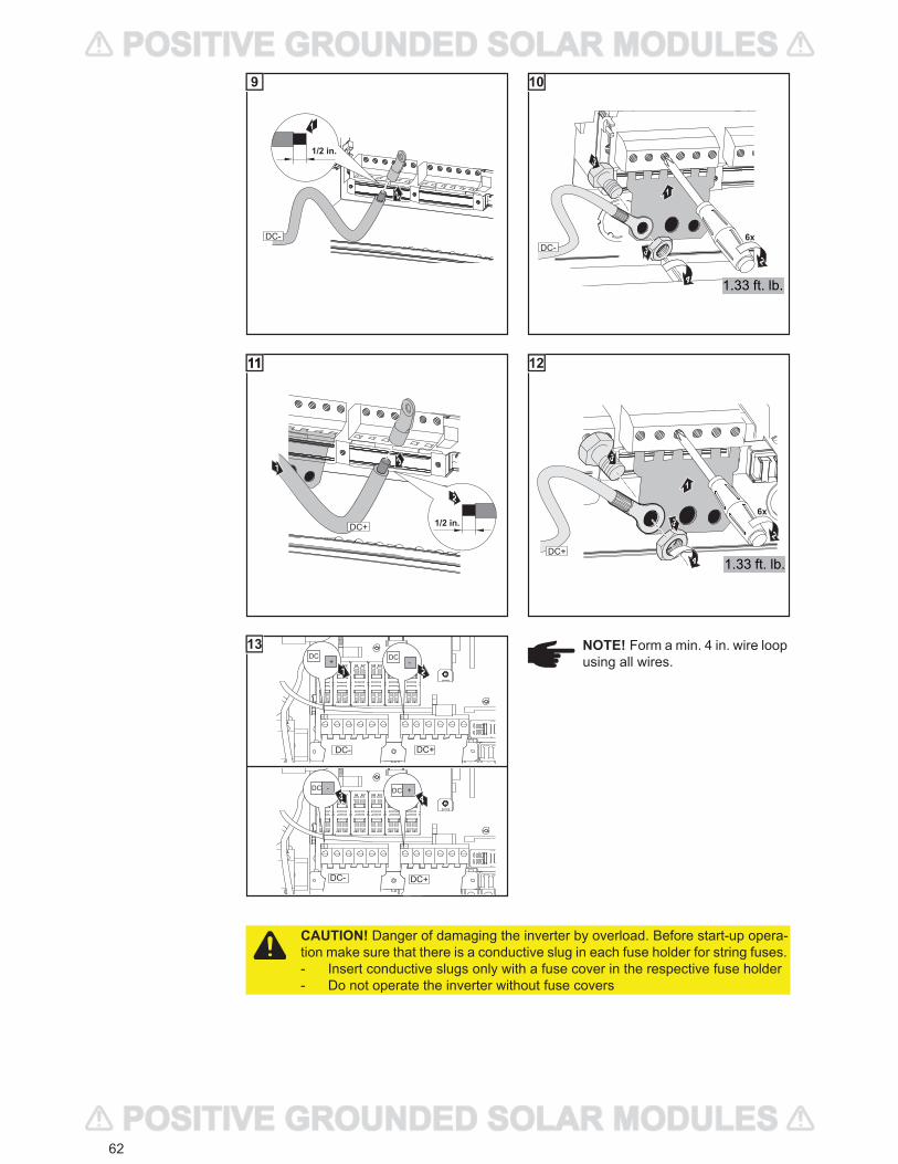
62
2
1/2 in.
1
DC-
9
3
1
6x
23
4
DC-
1.33 ft. lb.
10
3
1/2 in.
2
1
DC+
1111
2
3
6x
4
3
1
DC+1.33 ft. lb.
12
DC + DC -
DC+ DC
DC - DC +
DC - DC
-
+
1
3
2
4
DC- DC+
DC+DC-
13 NOTE! Form a min. 4 in. wire loop using all wires.
CAUTION! Danger of damaging the inverter by overload. Before start-up opera-tion make sure that there is a conductive slug in each fuse holder for string fuses. - Insert conductive slugs only with a fuse cover in the respective fuse holder- Do not operate the inverter without fuse covers
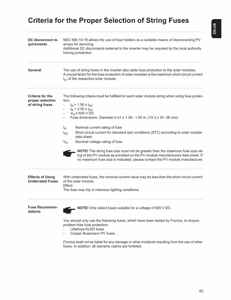
63
EN-U
S
Criteria for the Proper Selection of String Fuses
DC disconnect re-quirements
NEC 690.15-18 allows the use of fuse holders as a suitable means of disconnecting PV arrays for servicing.Additional DC disconnects external to the inverter may be required by the local authority having jurisdiction.
General The use of string fuses in the inverter also adds fuse protection to the solar modules.A crucial factor for the fuse protection of solar modules is the maximum short circuit current Isc of the respective solar module.
Criteria for the proper selection of string fuses
The following criteria must be fulfilled for each solar module string when using fuse protec-tion:- IN > 1.56 x ISC- IN < 2.00 x ISC- VN 600 V DC- Fuse dimensions: Diameter 0.41 x 1.38 - 1.50 in. (10.3 x 35 -38 mm)
IN Nominal current rating of fuseISC Short circuit current for standard test conditions (STC) according to solar module
data sheetVN Nominal voltage rating of fuse
Effects of Using Underrated Fuses
With underrated fuses, the nominal current value may be less than the short circuit current of the solar module.Effect:The fuse may trip in intensive lighting conditions.
Fuse Recommen-dations
You should only use the following fuses, which have been tested by Fronius, to ensure problem-free fuse protection:- Littelfuse KLKD fuses- Cooper Bussmann PV fuses
Fronius shall not be liable for any damage or other incidents resulting from the use of other fuses. In addition, all warranty claims are forfeited.
NOTE! The string fuse size must not be greater than the maximum fuse size rat-ing of the PV module as provided on the PV module manufacturers data sheet. If no maximum fuse size is indicated, please contact the PV module manufacturer.
NOTE! Only select fuses suitable for a voltage of 600 V DC.
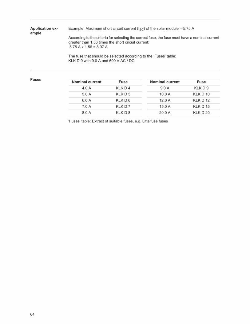
64
Application ex-ample
Example: Maximum short circuit current (ISC) of the solar module = 5.75 A
According to the criteria for selecting the correct fuse, the fuse must have a nominal current greater than 1.56 times the short circuit current: 5.75 A x 1.56 = 8.97 A
The fuse that should be selected according to the ‘Fuses’ table: KLK D 9 with 9.0 A and 600 V AC / DC
Fuses
'Fuses' table: Extract of suitable fuses, e.g. Littelfuse fuses
Nominal current Fuse Nominal current Fuse4.0 A KLK D 4 9.0 A KLK D 95.0 A KLK D 5 10.0 A KLK D 106.0 A KLK D 6 12.0 A KLK D 127.0 A KLK D 7 15.0 A KLK D 158.0 A KLK D 8 20.0 A KLK D 20
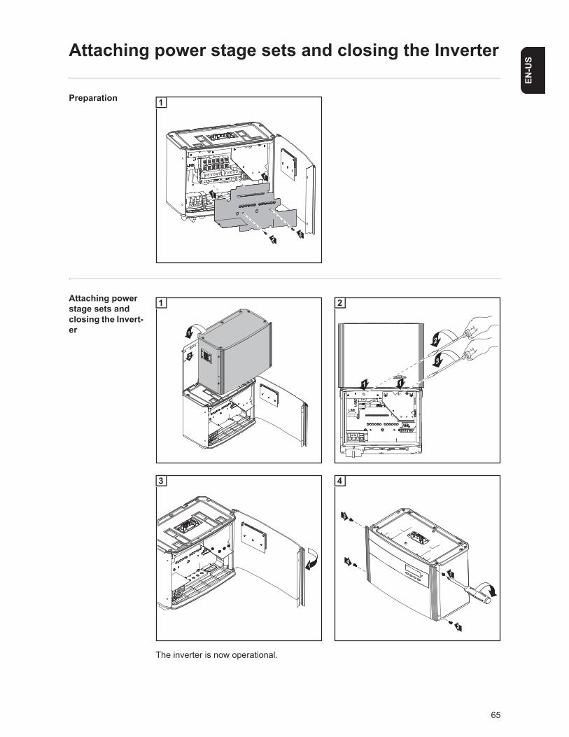
65
EN-U
S
Attaching power stage sets and closing the Inverter
Preparation
Attaching power stage sets and closing the Invert-er
The inverter is now operational.
1
1
32
1
2
1
1
1
2
3
1
2
1
3
3
2
4 1
4
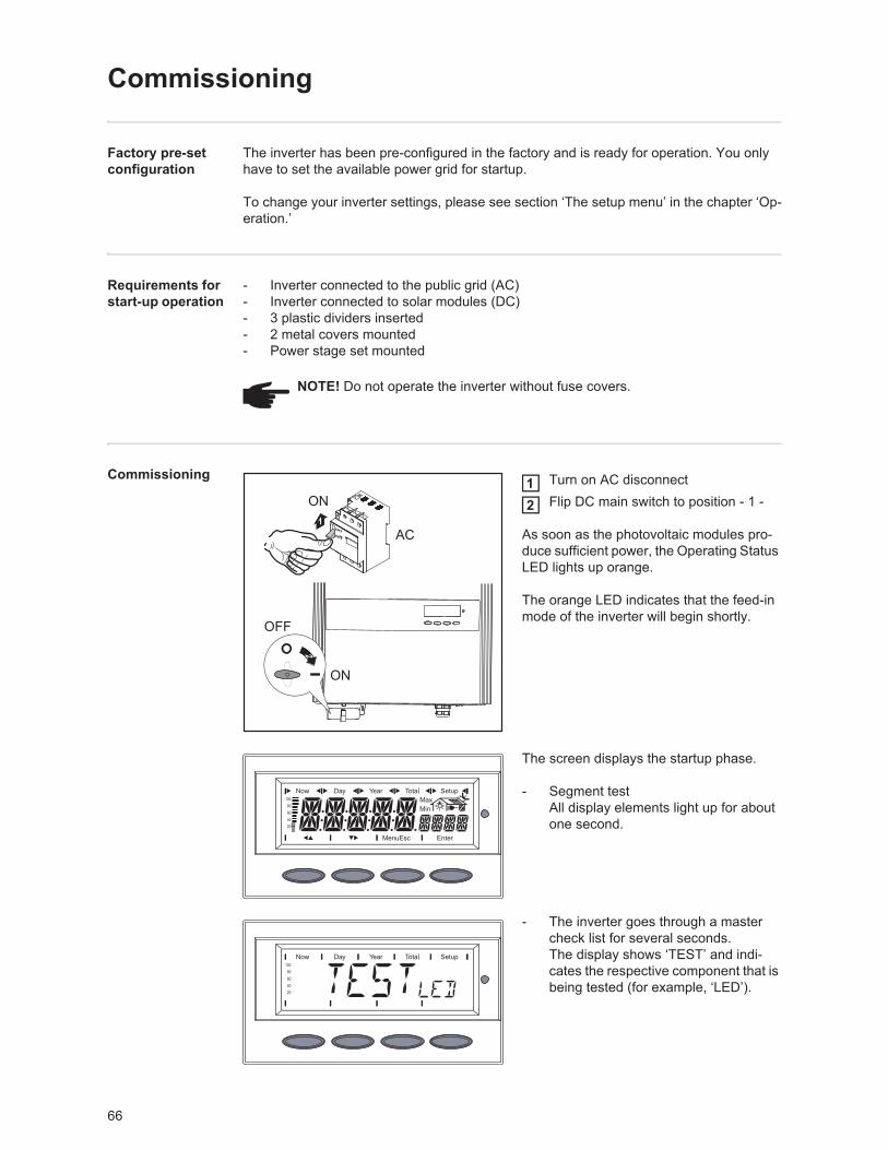
66
Commissioning
Factory pre-set configuration
The inverter has been pre-configured in the factory and is ready for operation. You only have to set the available power grid for startup.
To change your inverter settings, please see section ‘The setup menu’ in the chapter ‘Op-eration.’
Requirements for start-up operation
- Inverter connected to the public grid (AC)- Inverter connected to solar modules (DC)- 3 plastic dividers inserted- 2 metal covers mounted- Power stage set mounted
Commissioning Turn on AC disconnectFlip DC main switch to position - 1 -
As soon as the photovoltaic modules pro-duce sufficient power, the Operating Status LED lights up orange.
The orange LED indicates that the feed-in mode of the inverter will begin shortly.
The screen displays the startup phase.
- Segment testAll display elements light up for about one second.
- The inverter goes through a master check list for several seconds.The display shows ‘TEST’ and indi-cates the respective component that is being tested (for example, ‘LED’).
NOTE! Do not operate the inverter without fuse covers.
off
on1
ON
AC
2
ON
OFF
12
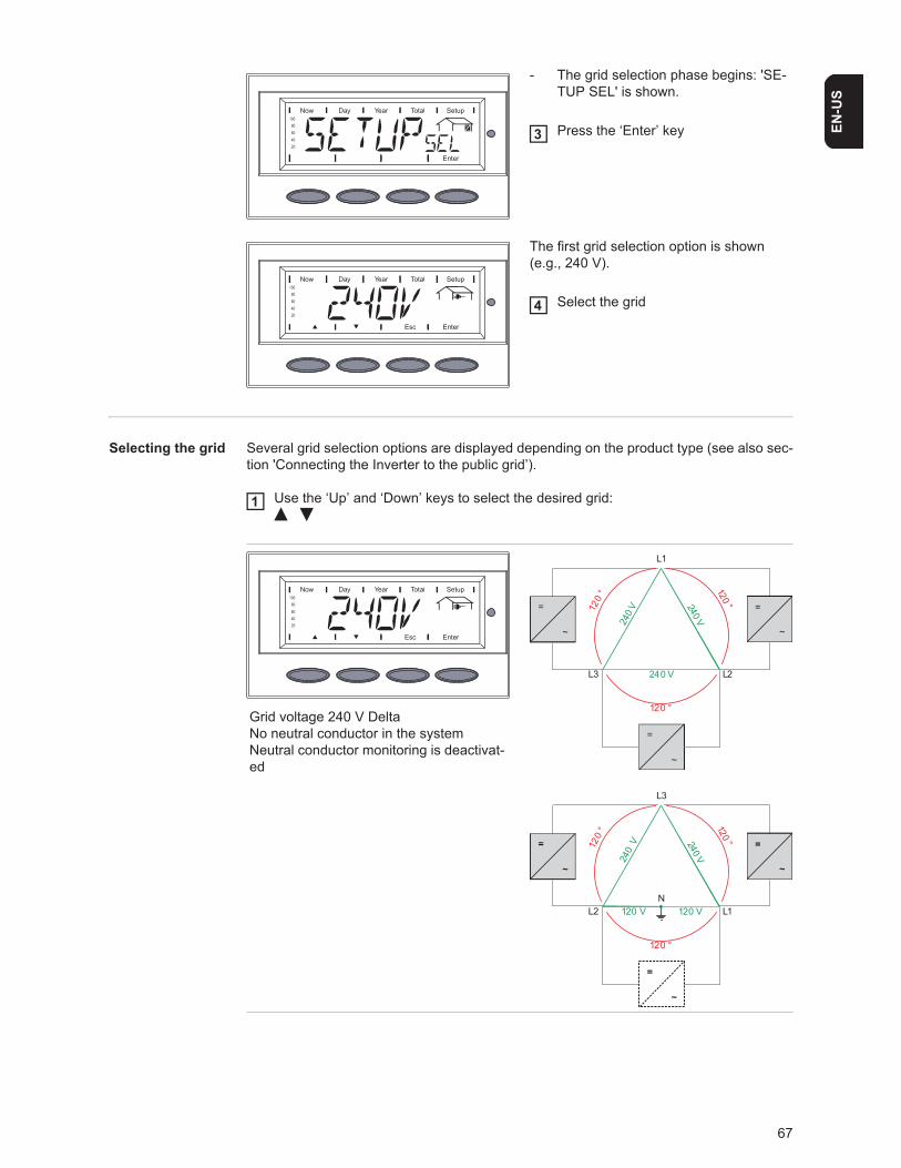
67
EN-U
S
- The grid selection phase begins: 'SE-TUP SEL' is shown.
Press the ‘Enter’ key
The first grid selection option is shown (e.g., 240 V).
Select the grid
Selecting the grid Several grid selection options are displayed depending on the product type (see also sec-tion 'Connecting the Inverter to the public grid’).
Use the ‘Up’ and ‘Down’ keys to select the desired grid:
3
4
Grid voltage 240 V DeltaNo neutral conductor in the systemNeutral conductor monitoring is deactivat-ed
1
240 V240 V
240 V
120
° 120 °
120 °
L1
L2L3
=
~
=
~
=
~
240 V240
V120
° 120 °
120 °
120 V120 V
L3
L1N
L2
=
~
=
~
=
~
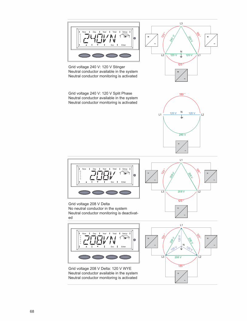
68
Grid voltage 240 V: 120 V StingerNeutral conductor available in the systemNeutral conductor monitoring is activated
Grid voltage 240 V: 120 V Split PhaseNeutral conductor available in the systemNeutral conductor monitoring is activated
Grid voltage 208 V DeltaNo neutral conductor in the systemNeutral conductor monitoring is deactivat-ed
Grid voltage 208 V Delta: 120 V WYENeutral conductor available in the systemNeutral conductor monitoring is activated
240 V240
V120
° 120 °
120 °
120 V120 V
L3
L1N
L2
=
~
=
~
=
~
180 °
120 V 120 V
240 V
2L1LN
=
~
120
° 120 °
120 °
208 V
208 V
208 V
L1
L2L3
=
~
=
~
=
~
120
V
120 V 120 V
120
° 120 °
120 °
208
V 208 V
208 V
L1
L2
N
L3
=
~
=
~
=
~
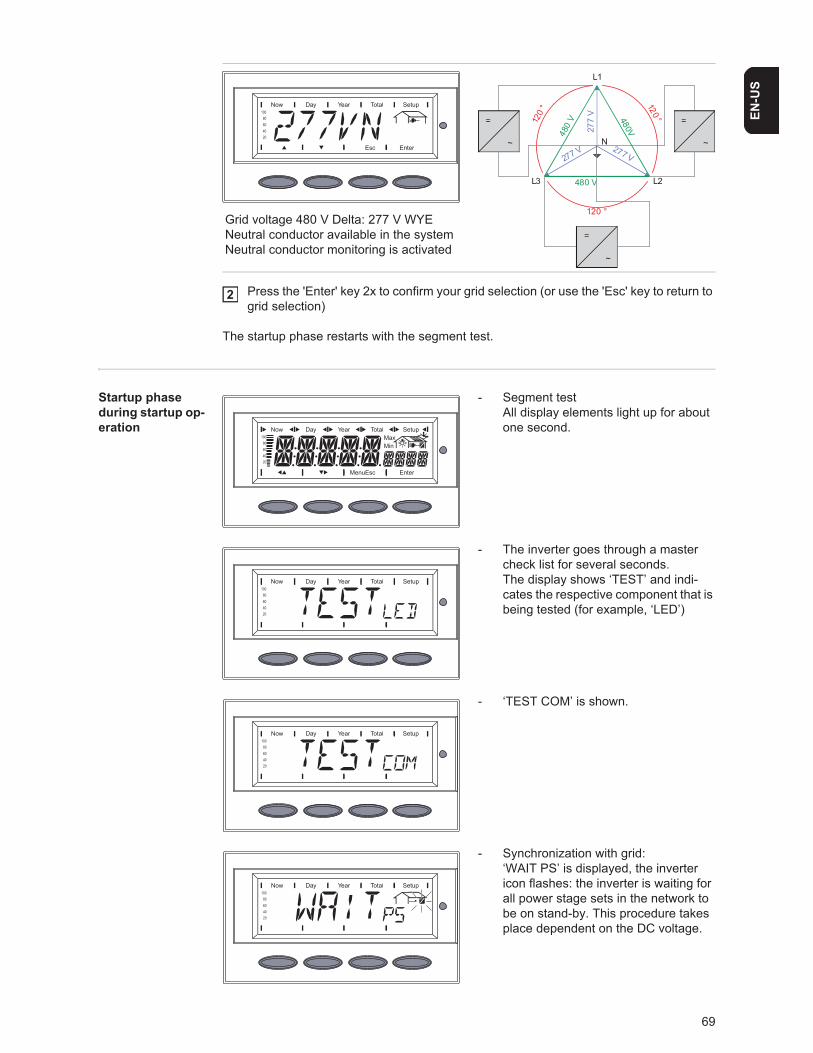
69
EN-U
S
Press the 'Enter' key 2x to confirm your grid selection (or use the 'Esc' key to return to grid selection)
The startup phase restarts with the segment test.
Startup phase during startup op-eration
- Segment testAll display elements light up for about one second.
- The inverter goes through a master check list for several seconds.The display shows ‘TEST’ and indi-cates the respective component that is being tested (for example, ‘LED’)
- ‘TEST COM’ is shown.
- Synchronization with grid:‘WAIT PS’ is displayed, the inverter icon flashes: the inverter is waiting for all power stage sets in the network to be on stand-by. This procedure takes place dependent on the DC voltage.
Grid voltage 480 V Delta: 277 V WYENeutral conductor available in the systemNeutral conductor monitoring is activated
277
V
277 V 277 V
120
° 120 °
120 °
480
V 480V480 V
L1
L2
N
L3
=
~
=
~
=
~
2
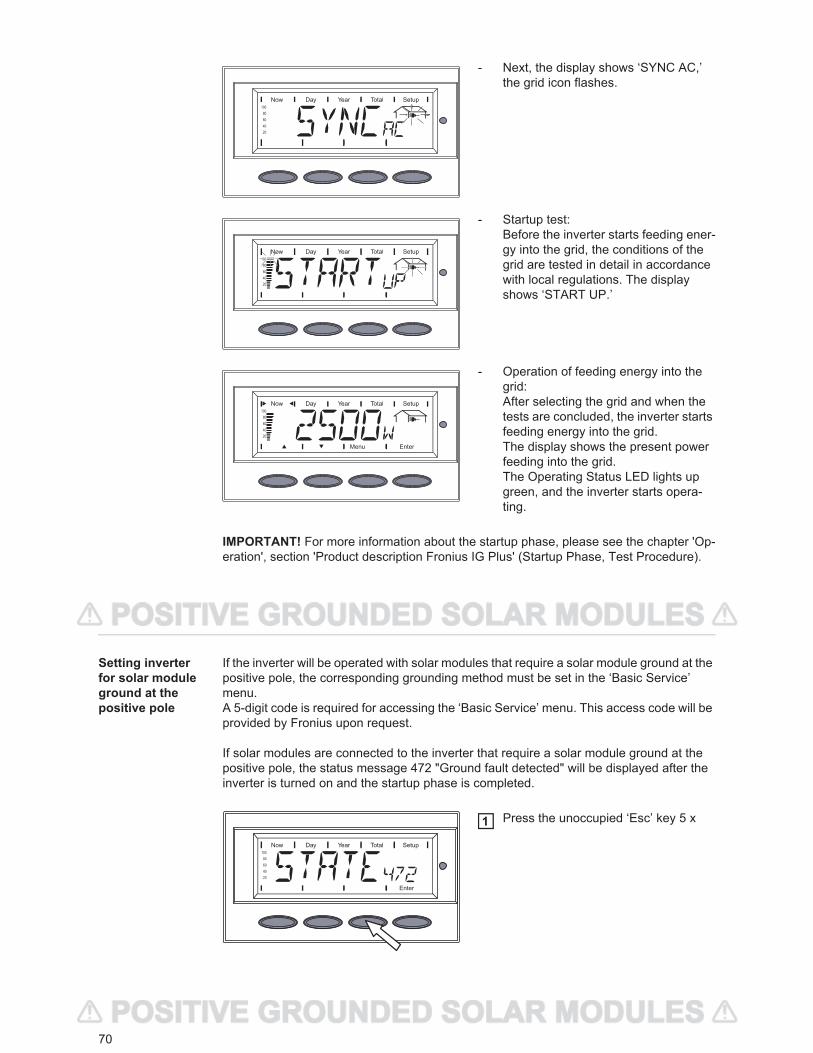
70
- Next, the display shows ‘SYNC AC,’ the grid icon flashes.
- Startup test:Before the inverter starts feeding ener-gy into the grid, the conditions of the grid are tested in detail in accordance with local regulations. The display shows ‘START UP.’
- Operation of feeding energy into the grid:After selecting the grid and when the tests are concluded, the inverter starts feeding energy into the grid.The display shows the present power feeding into the grid.The Operating Status LED lights up green, and the inverter starts opera-ting.
Setting inverter for solar module ground at the positive pole
If the inverter will be operated with solar modules that require a solar module ground at the positive pole, the corresponding grounding method must be set in the ‘Basic Service’ menu.A 5-digit code is required for accessing the ‘Basic Service’ menu. This access code will be provided by Fronius upon request.
If solar modules are connected to the inverter that require a solar module ground at the positive pole, the status message 472 "Ground fault detected" will be displayed after the inverter is turned on and the startup phase is completed.
Press the unoccupied ‘Esc’ key 5 x
IMPORTANT! For more information about the startup phase, please see the chapter 'Op-eration', section 'Product description Fronius IG Plus' (Startup Phase, Test Procedure).
1
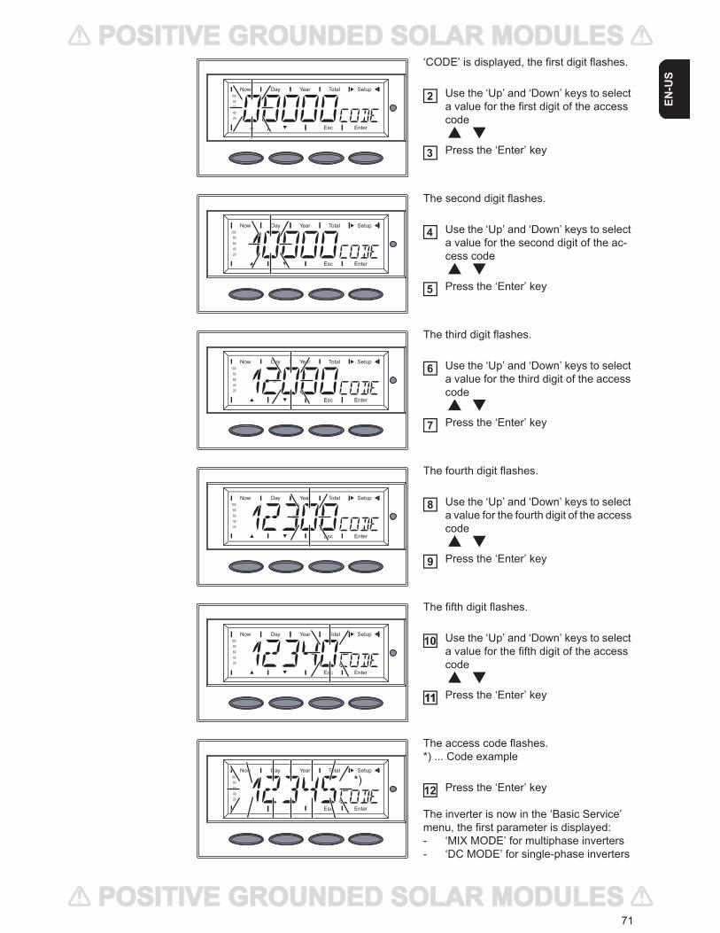
71
EN-U
S
‘CODE’ is displayed, the first digit flashes.
Use the ‘Up’ and ‘Down’ keys to select a value for the first digit of the access code
Press the ‘Enter’ key
The second digit flashes.
Use the ‘Up’ and ‘Down’ keys to select a value for the second digit of the ac-cess code
Press the ‘Enter’ key
The third digit flashes.
Use the ‘Up’ and ‘Down’ keys to select a value for the third digit of the access code
Press the ‘Enter’ key
The fourth digit flashes.
Use the ‘Up’ and ‘Down’ keys to select a value for the fourth digit of the access code
Press the ‘Enter’ key
The fifth digit flashes.
Use the ‘Up’ and ‘Down’ keys to select a value for the fifth digit of the access code
Press the ‘Enter’ key
The access code flashes.*) ... Code example
Press the ‘Enter’ key
The inverter is now in the ‘Basic Service’ menu, the first parameter is displayed:- ‘MIX MODE’ for multiphase inverters- ‘DC MODE’ for single-phase inverters
2
3
4
5
6
7
8
9
10
1111
*)12
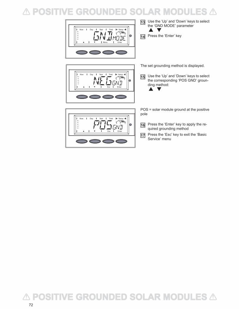
72
Use the ‘Up’ and ‘Down’ keys to select the ‘GND MODE’ parameter
Press the ‘Enter’ key
The set grounding method is displayed.
Use the ‘Up’ and ‘Down’ keys to select the corresponding ‘POS GND’ groun-ding method:
POS = solar module ground at the positive pole
Press the ‘Enter’ key to apply the re-quired grounding methodPress the ‘Esc’ key to exit the ‘Basic Service’ menu
13
14
15
16
17
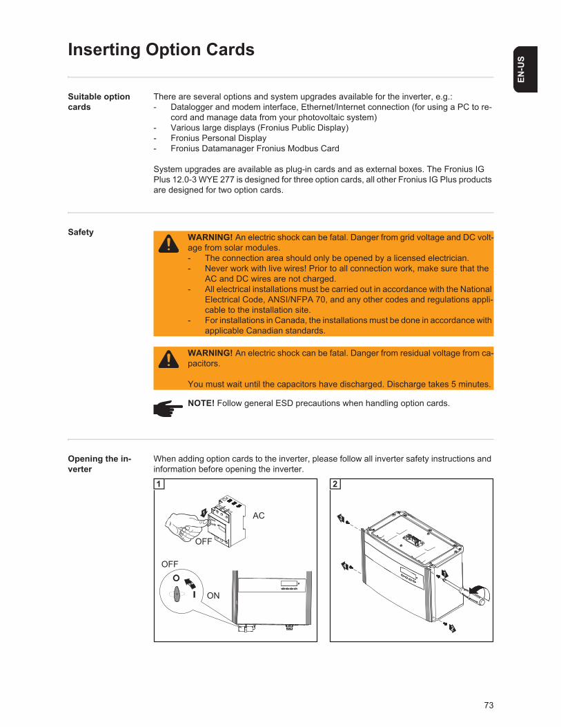
73
EN-U
S
Inserting Option Cards
Suitable option cards
There are several options and system upgrades available for the inverter, e.g.:- Datalogger and modem interface, Ethernet/Internet connection (for using a PC to re-
cord and manage data from your photovoltaic system)- Various large displays (Fronius Public Display)- Fronius Personal Display- Fronius Datamanager Fronius Modbus Card
System upgrades are available as plug-in cards and as external boxes. The Fronius IG Plus 12.0-3 WYE 277 is designed for three option cards, all other Fronius IG Plus products are designed for two option cards.
Safety
Opening the in-verter
When adding option cards to the inverter, please follow all inverter safety instructions and information before opening the inverter.
WARNING! An electric shock can be fatal. Danger from grid voltage and DC volt-age from solar modules.- The connection area should only be opened by a licensed electrician.- Never work with live wires! Prior to all connection work, make sure that the
AC and DC wires are not charged.- All electrical installations must be carried out in accordance with the National
Electrical Code, ANSI/NFPA 70, and any other codes and regulations appli-cable to the installation site.
- For installations in Canada, the installations must be done in accordance with applicable Canadian standards.
WARNING! An electric shock can be fatal. Danger from residual voltage from ca-pacitors.
You must wait until the capacitors have discharged. Discharge takes 5 minutes.
NOTE! Follow general ESD precautions when handling option cards.
off
on
1
2
OFF
AC
OFF
ON
1
14
2
3
2
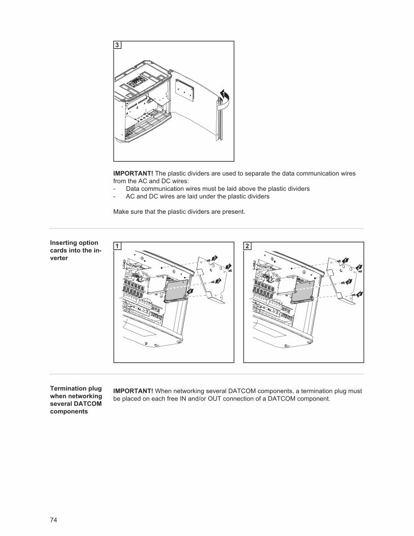
74
Inserting option cards into the in-verter
Termination plug when networking several DATCOM components
1
3
IMPORTANT! The plastic dividers are used to separate the data communication wires from the AC and DC wires:- Data communication wires must be laid above the plastic dividers- AC and DC wires are laid under the plastic dividers
Make sure that the plastic dividers are present.
4
1
3
2
1
1
3
4
2
2
IMPORTANT! When networking several DATCOM components, a termination plug must be placed on each free IN and/or OUT connection of a DATCOM component.
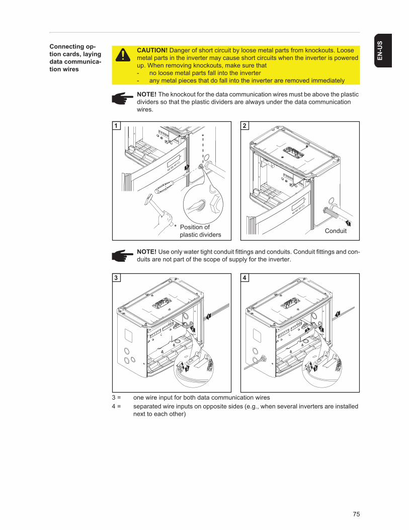
75
EN-U
SConnecting op-tion cards, laying data communica-tion wires
3 = one wire input for both data communication wires4 = separated wire inputs on opposite sides (e.g., when several inverters are installed
next to each other)
CAUTION! Danger of short circuit by loose metal parts from knockouts. Loose metal parts in the inverter may cause short circuits when the inverter is powered up. When removing knockouts, make sure that - no loose metal parts fall into the inverter- any metal pieces that do fall into the inverter are removed immediately
NOTE! The knockout for the data communication wires must be above the plastic dividers so that the plastic dividers are always under the data communication wires.
NOTE! Use only water tight conduit fittings and conduits. Conduit fittings and con-duits are not part of the scope of supply for the inverter.
1
1
* Position of
*
plastic dividers Conduit
1 2
2
1
2
21
1
2
3 4
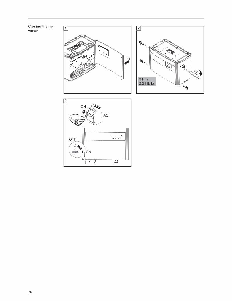
76
Closing the in-verter
1
1
3
2
4 1
3 Nm2.21 ft. lb.
2
off
on1
ON
AC
2ON
OFF
3
77
EN-U
S
Data Communication and Solar Net
Solar Net and data interface Fronius developed Solar Net to make these add-on system components flexible and ca-
pable of being used in a wide variety of different applications. Solar Net is a data network that enables several inverters to be linked with the data communications components.Solar Net is a bus system. A single cable is all that is required for one or more inverters to communicate with all system upgrade components.The core of the Solar Net is the Fronius Datalogger. It coordinates data transmissions and ensures that even large volumes of data are distributed quickly and securely.The ‘Fronius Com Card’ is used to integrate the inverter into Solar Net.
Important Every inverter that is to be monitored using a Datalogger requires a ‘Fronius Com Card.’ In this case, the ‘Fronius Com Card’ serves as a link between the internal net-work of the inverter and the Solar Net interface of the Datalogger.
Important Each inverter can have only one ‘Fronius Com Card.’ A network may only con-tain one Fronius Datalogger.The first inverter with a ‘Fronius Com Card’ can be positioned up to 3280 ft. (1000 m) away from the last inverter with a ‘Fronius Com Card.’Different system upgrades are detected automatically by Solar Net.In order to distinguish among several identical system upgrades, each one must be as-signed a unique number.In order to uniquely identify each inverter in Solar Net, each inverter must also be as-signed an individual number. You can assign individual numbers as per ‘The setup menu’ section in this manual.More detailed information on the individual data communications components can be found in the relevant operating instructions or on the Internet at http:\\www.fronius-usa.com.
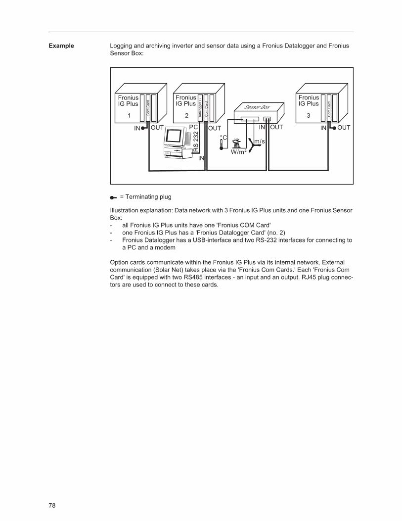
78
Example Logging and archiving inverter and sensor data using a Fronius Datalogger and Fronius Sensor Box:
Illustration explanation: Data network with 3 Fronius IG Plus units and one Fronius Sensor Box:- all Fronius IG Plus units have one 'Fronius COM Card' - one Fronius IG Plus has a 'Fronius Datalogger Card' (no. 2)- Fronius Datalogger has a USB-interface and two RS-232 interfaces for connecting to
a PC and a modem
Option cards communicate within the Fronius IG Plus via its internal network. External communication (Solar Net) takes place via the 'Fronius Com Cards.' Each 'Fronius Com Card' is equipped with two RS485 interfaces - an input and an output. RJ45 plug connec-tors are used to connect to these cards.
= Terminating plug
1 2 3
FroniusIG Plus
FroniusIG Plus
FroniusIG Plus
Com
Car
d
Dat
alog
ger C
.
IN OUT
Com
Car
d
Com
Car
d
IN
OUT
RS
232
IN OUT
Sensor Box
IN OUT
°C
W/m²
m/s
PC
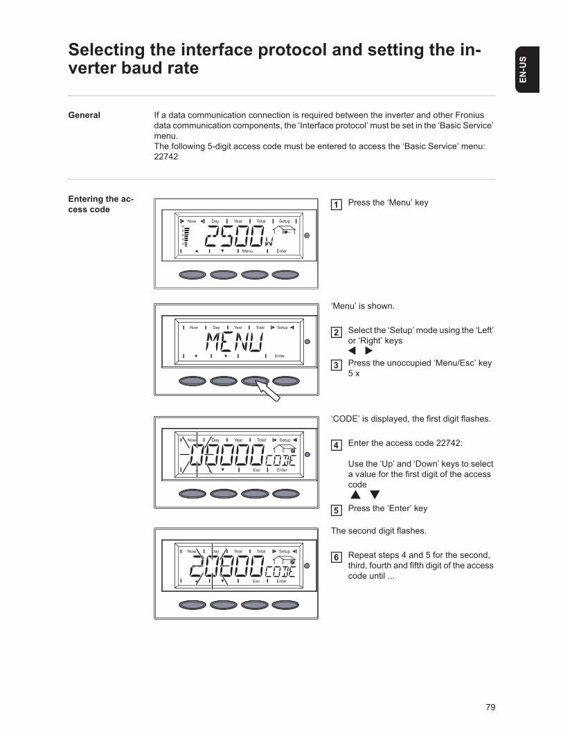
79
EN-U
S
Selecting the interface protocol and setting the in-verter baud rate
General If a data communication connection is required between the inverter and other Fronius data communication components, the ‘Interface protocol’ must be set in the ‘Basic Service’ menu.The following 5-digit access code must be entered to access the ‘Basic Service’ menu:22742
Entering the ac-cess code
Press the ‘Menu’ key
‘Menu’ is shown.
Select the ‘Setup’ mode using the ‘Left’ or ‘Right’ keys
Press the unoccupied ‘Menu/Esc’ key 5 x
‘CODE’ is displayed, the first digit flashes.
Enter the access code 22742:
Use the ‘Up’ and ‘Down’ keys to select a value for the first digit of the access code
Press the ‘Enter’ key
The second digit flashes.
Repeat steps 4 and 5 for the second, third, fourth and fifth digit of the access code until ...
1
2
3
4
5
6
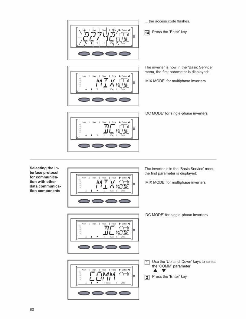
80
... the access code flashes.
Press the ‘Enter’ key
The inverter is now in the ‘Basic Service’ menu, the first parameter is displayed:
‘MIX MODE’ for multiphase inverters
‘DC MODE’ for single-phase inverters
Selecting the in-terface protocol for communica-tion with other data communica-tion components
The inverter is in the ‘Basic Service’ menu, the first parameter is displayed:
‘MIX MODE’ for multiphase inverters
‘DC MODE’ for single-phase inverters
Use the ‘Up’ and ‘Down’ keys to select the ‘COMM’ parameter
Press the ‘Enter’ key
14
1
2
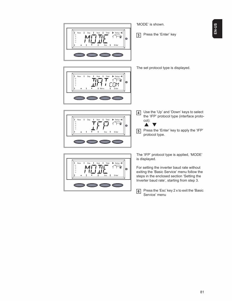
81
EN-U
S‘MODE’ is shown.
Press the ‘Enter’ key
The set protocol type is displayed.
Use the ‘Up’ and ‘Down’ keys to select the ‘IFP’ protocol type (interface proto-col):
Press the ‘Enter’ key to apply the ‘IFP’ protocol type.
The ‘IFP’ protocol type is applied, ‘MODE’ is displayed.
For setting the inverter baud rate without exiting the ‘Basic Service’ menu follow the steps in the enclosed section ‘Setting the Inverter baud rate’, starting from step 3.
Press the ‘Esc’ key 2 x to exit the ‘Basic Service’ menu
3
4
5
6
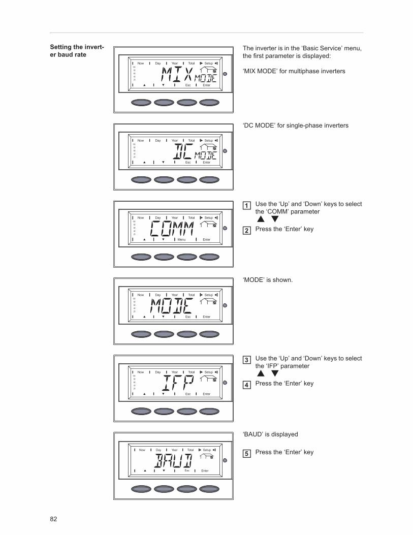
82
Setting the invert-er baud rate
The inverter is in the ‘Basic Service’ menu, the first parameter is displayed:
‘MIX MODE’ for multiphase inverters
‘DC MODE’ for single-phase inverters
Use the ‘Up’ and ‘Down’ keys to select the ‘COMM’ parameter
Press the ‘Enter’ key
‘MODE’ is shown.
Use the ‘Up’ and ‘Down’ keys to select the ‘IFP’ parameter
Press the ‘Enter’ key
‘BAUD’ is displayed
Press the ‘Enter’ key
1
2
3
4
5
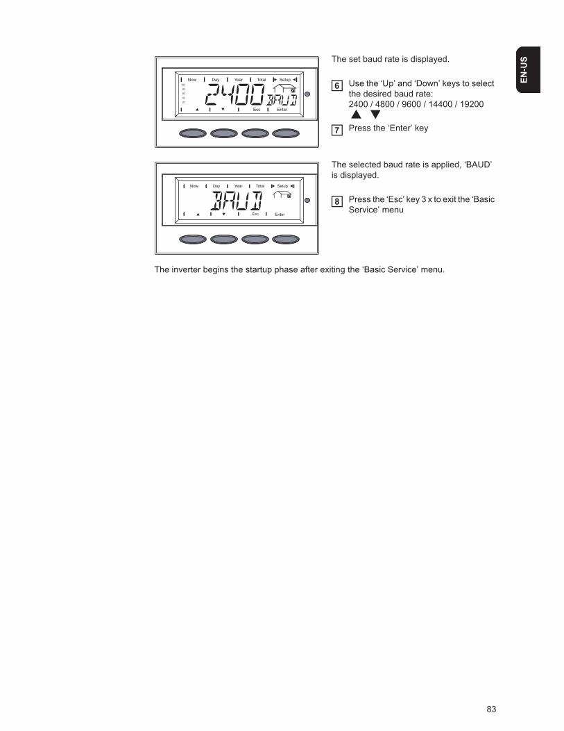
83
EN-U
SThe set baud rate is displayed.
Use the ‘Up’ and ‘Down’ keys to select the desired baud rate:2400 / 4800 / 9600 / 14400 / 19200
Press the ‘Enter’ key
The selected baud rate is applied, ‘BAUD’ is displayed.
Press the ‘Esc’ key 3 x to exit the ‘Basic Service’ menu
The inverter begins the startup phase after exiting the ‘Basic Service’ menu.
6
7
8
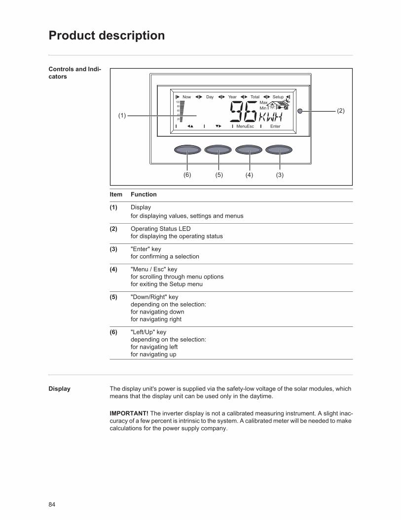
84
Product description
Controls and Indi-cators
Item Function
(1) Displayfor displaying values, settings and menus
(2) Operating Status LEDfor displaying the operating status
(3) "Enter" keyfor confirming a selection
(4) "Menu / Esc" keyfor scrolling through menu optionsfor exiting the Setup menu
(5) "Down/Right" keydepending on the selection:for navigating downfor navigating right
(6) "Left/Up" keydepending on the selection:for navigating leftfor navigating up
Display The display unit's power is supplied via the safety-low voltage of the solar modules, which means that the display unit can be used only in the daytime.
(1)
(6) (5) (4) (3)
(2)
IMPORTANT! The inverter display is not a calibrated measuring instrument. A slight inac-curacy of a few percent is intrinsic to the system. A calibrated meter will be needed to make calculations for the power supply company.
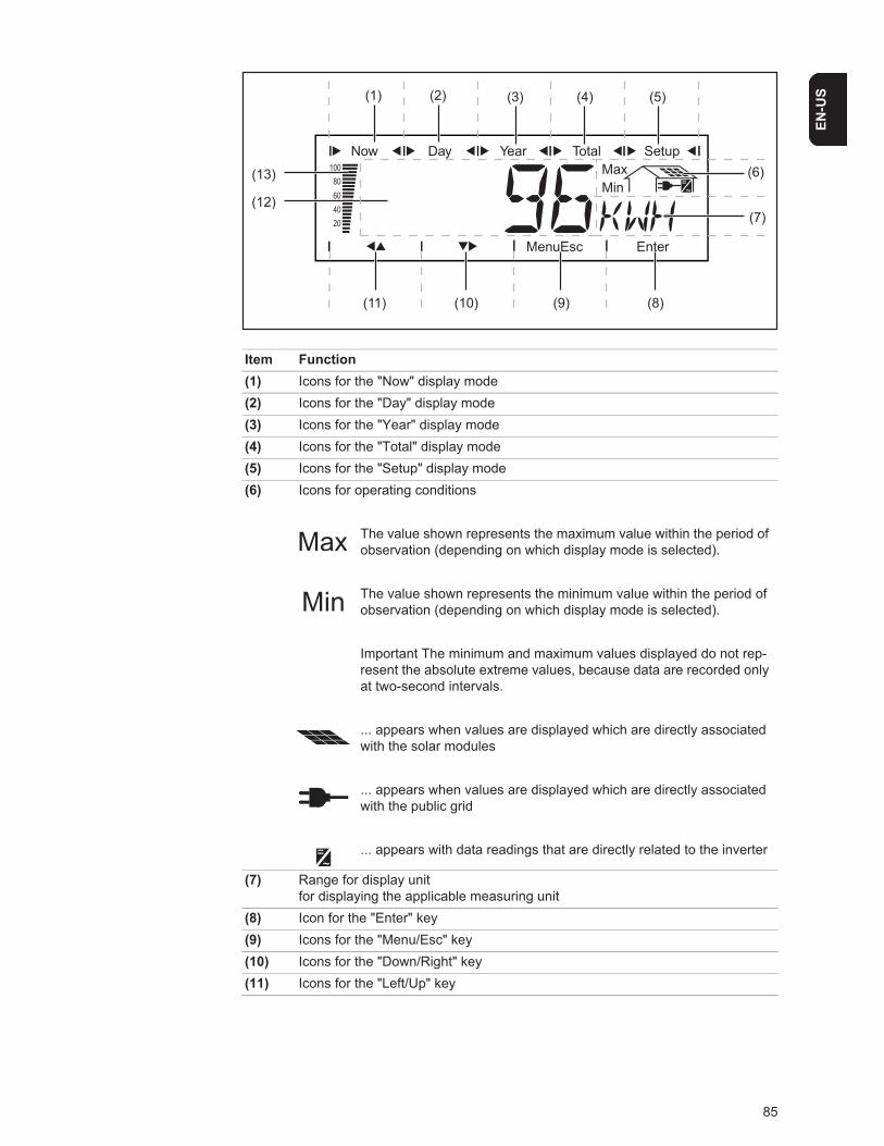
85
EN-U
S
Item Function(1) Icons for the "Now" display mode(2) Icons for the "Day" display mode(3) Icons for the "Year" display mode(4) Icons for the "Total" display mode(5) Icons for the "Setup" display mode(6) Icons for operating conditions
The value shown represents the maximum value within the period of observation (depending on which display mode is selected).
The value shown represents the minimum value within the period of observation (depending on which display mode is selected).
Important The minimum and maximum values displayed do not rep-resent the absolute extreme values, because data are recorded only at two-second intervals.
... appears when values are displayed which are directly associated with the solar modules
... appears when values are displayed which are directly associated with the public grid
... appears with data readings that are directly related to the inverter
(7) Range for display unitfor displaying the applicable measuring unit
(8) Icon for the "Enter" key(9) Icons for the "Menu/Esc" key(10) Icons for the "Down/Right" key(11) Icons for the "Left/Up" key
(11) (10)
(3) (4) (5)
(6)
(7)
(13)
(12)
(9) (8)
(1) (2)
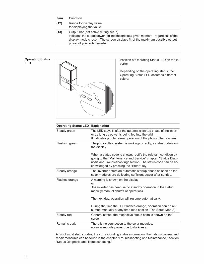
86
Operating Status LED
Position of Operating Status LED on the in-verter
Depending on the operating status, the Operating Status LED assumes different colors:
A list of most status codes, the corresponding status information, their status causes and repair measures can be found in the chapter "Troubleshooting and Maintenance," section "Status Diagnosis and Troubleshooting."
(12) Range for display valuefor displaying the value
(13) Output bar (not active during setup)indicates the output power fed into the grid at a given moment - regardless of the display mode chosen. The screen displays % of the maximum possible output power of your solar inverter
Item Function
Operating Status LED ExplanationSteady green The LED stays lit after the automatic startup phase of the invert-
er as long as power is being fed into the grid.It indicates problem-free operation of the photovoltaic system.
Flashing green The photovoltaic system is working correctly, a status code is on the display.
When a status code is shown, rectify the relevant condition by going to the "Maintenance and Service" chapter, "Status Diag-nosis and Troubleshooting" section. The status code can be ac-knowledged by pressing the "Enter" key.
Steady orange The inverter enters an automatic startup phase as soon as the solar modules are delivering sufficient power after sunrise.
Flashes orange A warning is shown on the display or the inverter has been set to standby operation in the Setup menu (= manual shutoff of operation).
The next day, operation will resume automatically.
During the time the LED flashes orange, operation can be re-sumed manually at any time (see section "The Setup Menu")
Steady red General status: the respective status code is shown on the screen
Remains dark There is no connection to the solar modules, no solar module power due to darkness.
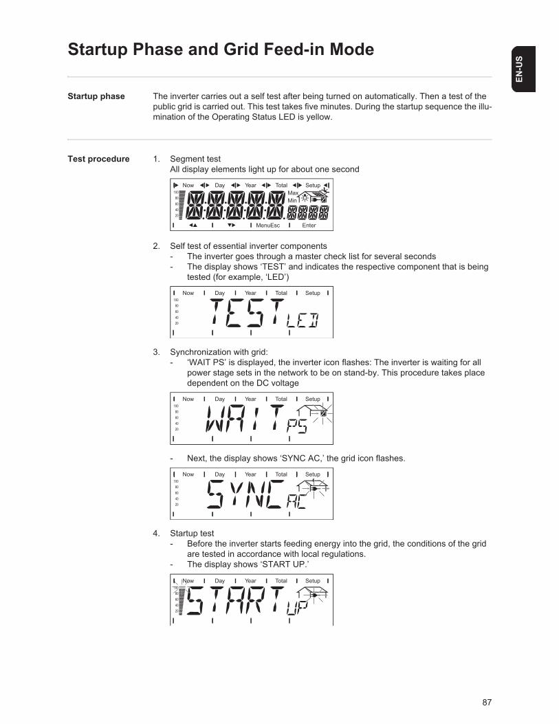
87
EN-U
S
Startup Phase and Grid Feed-in Mode
Startup phase The inverter carries out a self test after being turned on automatically. Then a test of the public grid is carried out. This test takes five minutes. During the startup sequence the illu-mination of the Operating Status LED is yellow.
Test procedure 1. Segment testAll display elements light up for about one second
2. Self test of essential inverter components- The inverter goes through a master check list for several seconds - The display shows ‘TEST’ and indicates the respective component that is being
tested (for example, ‘LED’)
3. Synchronization with grid:- ‘WAIT PS’ is displayed, the inverter icon flashes: The inverter is waiting for all
power stage sets in the network to be on stand-by. This procedure takes place dependent on the DC voltage
- Next, the display shows ‘SYNC AC,’ the grid icon flashes.
4. Startup test- Before the inverter starts feeding energy into the grid, the conditions of the grid
are tested in accordance with local regulations.- The display shows ‘START UP.’
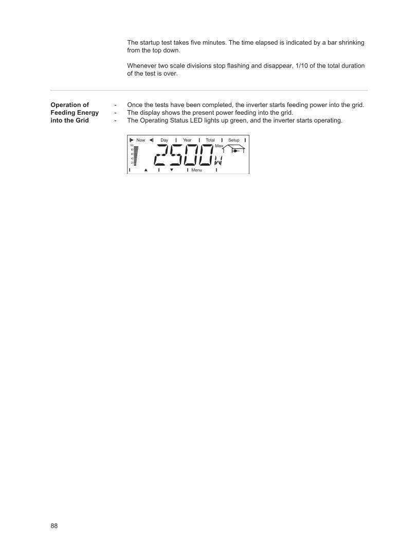
88
The startup test takes five minutes. The time elapsed is indicated by a bar shrinking from the top down.
Whenever two scale divisions stop flashing and disappear, 1/10 of the total duration of the test is over.
Operation of Feeding Energy into the Grid
- Once the tests have been completed, the inverter starts feeding power into the grid.- The display shows the present power feeding into the grid.- The Operating Status LED lights up green, and the inverter starts operating.
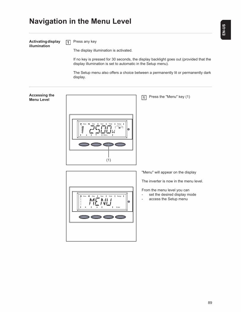
89
EN-U
S
Navigation in the Menu Level
Activating display illumination
Press any key
The display illumination is activated.
If no key is pressed for 30 seconds, the display backlight goes out (provided that the display illumination is set to automatic in the Setup menu).
The Setup menu also offers a choice between a permanently lit or permanently dark display.
Accessing the Menu Level
Press the "Menu" key (1)
"Menu" will appear on the display
The inverter is now in the menu level.
From the menu level you can- set the desired display mode- access the Setup menu
1
(1)
1
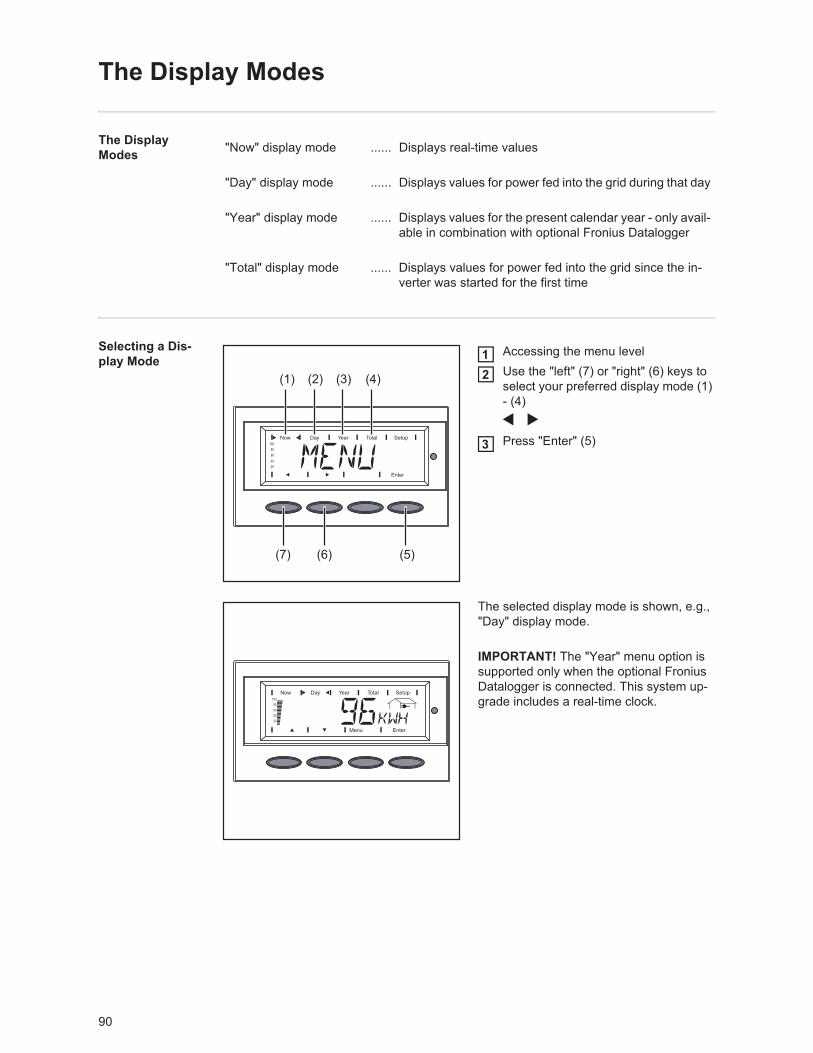
90
The Display Modes
The Display Modes
Selecting a Dis-play Mode
Accessing the menu level Use the "left" (7) or "right" (6) keys to select your preferred display mode (1) - (4)
Press "Enter" (5)
The selected display mode is shown, e.g., "Day" display mode.
"Now" display mode ...... Displays real-time values
"Day" display mode ...... Displays values for power fed into the grid during that day
"Year" display mode ...... Displays values for the present calendar year - only avail-able in combination with optional Fronius Datalogger
"Total" display mode ...... Displays values for power fed into the grid since the in-verter was started for the first time
(7)
(1) (2) (3) (4)
(6) (5)
12
3
IMPORTANT! The "Year" menu option is supported only when the optional Fronius Datalogger is connected. This system up-grade includes a real-time clock.
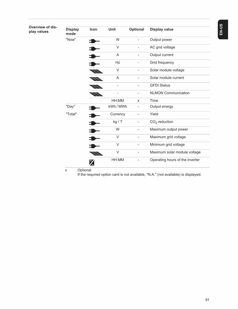
91
EN-U
SOverview of dis-play values
x Optional If the required option card is not available, "N.A." (not available) is displayed.
Display mode
Icon Unit Optional Display value
"Now" W - Output power
V - AC grid voltage
A - Output current
Hz - Grid frequency
V - Solar module voltage
A - Solar module current
- - GFDI Status
- - NLMON Communication
HH:MM x Time"Day" kWh / MWh - Output energy
"Total" Currency - Yield
kg / T - CO2 reduction
W - Maximum output power
V - Maximum grid voltage
V - Minimum grid voltage
V - Maximum solar module voltage
HH:MM - Operating hours of the inverter
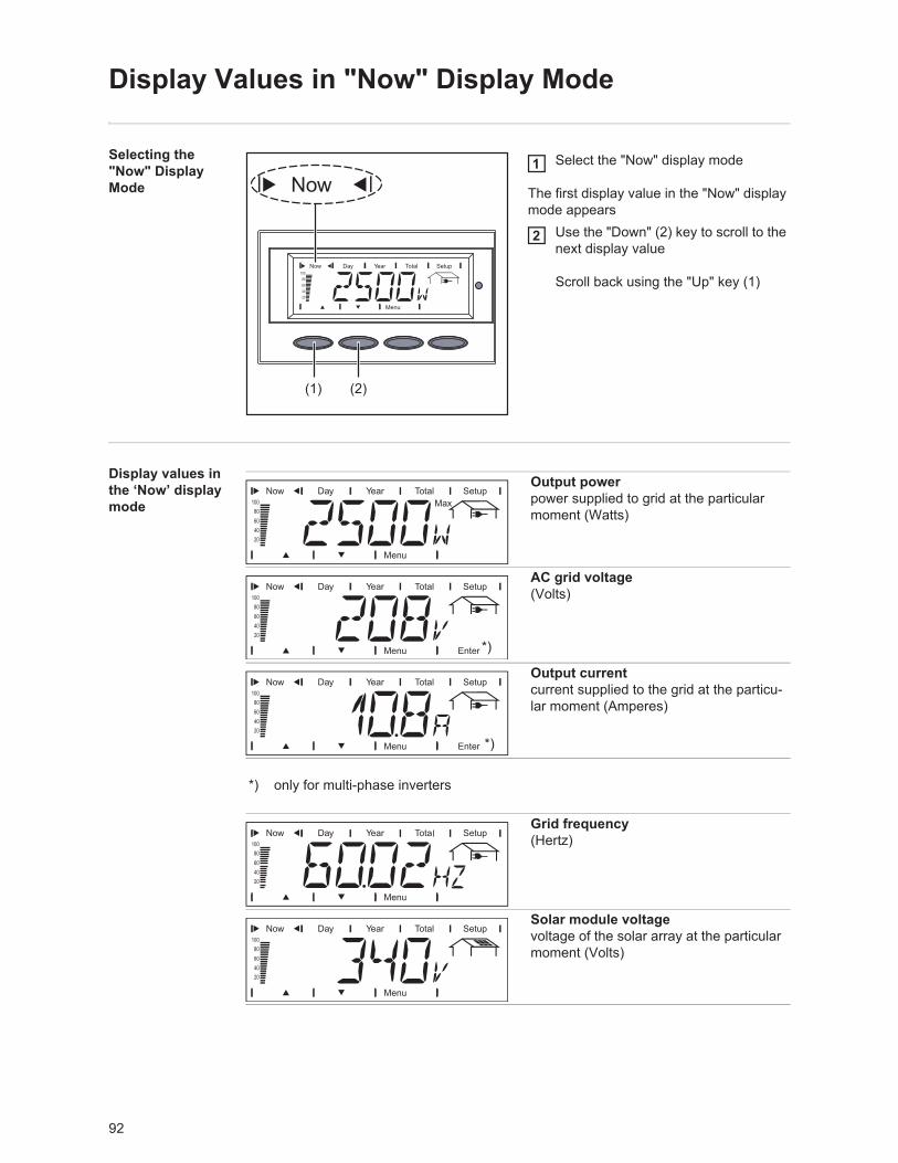
92
Display Values in "Now" Display Mode
Selecting the "Now" Display Mode
Select the "Now" display mode
The first display value in the "Now" display mode appears
Use the "Down" (2) key to scroll to the next display value
Scroll back using the "Up" key (1)
Display values in the ‘Now’ display mode
(1) (2)
1
2
Output powerpower supplied to grid at the particular moment (Watts)
AC grid voltage(Volts)
Output currentcurrent supplied to the grid at the particu-lar moment (Amperes)
*) only for multi-phase inverters
Grid frequency(Hertz)
Solar module voltagevoltage of the solar array at the particular moment (Volts)
*)
*)
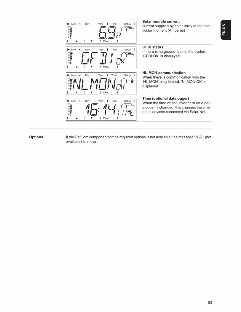
93
EN-U
S
Options If the DatCom component for the required options is not available, the message "N.A." (not available) is shown.
Solar module currentcurrent supplied by solar array at the par-ticular moment (Amperes)
GFDI statusIf there is no ground fault in the system, ‘GFDI OK’ is displayed
NL-MON communicationWhen there is communication with the ‘NL-MON’ plug-in card, ‘NLMON OK’ is displayed
Time (optional datalogger)When the time on the inverter or on a dat-alogger is changed, this changes the time on all devices connected via Solar Net.
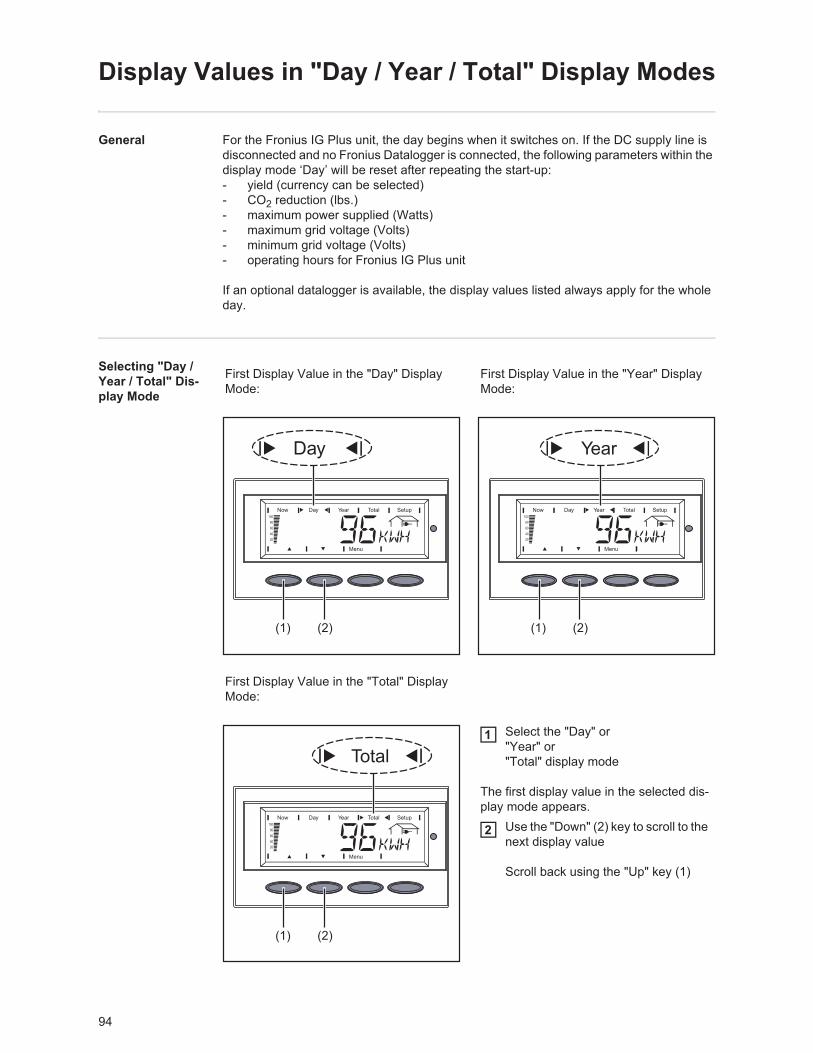
94
Display Values in "Day / Year / Total" Display Modes
General For the Fronius IG Plus unit, the day begins when it switches on. If the DC supply line is disconnected and no Fronius Datalogger is connected, the following parameters within the display mode ‘Day’ will be reset after repeating the start-up:- yield (currency can be selected)- CO2 reduction (lbs.)- maximum power supplied (Watts)- maximum grid voltage (Volts)- minimum grid voltage (Volts)- operating hours for Fronius IG Plus unit
If an optional datalogger is available, the display values listed always apply for the whole day.
Selecting "Day / Year / Total" Dis-play Mode
First Display Value in the "Day" Display Mode:
First Display Value in the "Year" Display Mode:
First Display Value in the "Total" Display Mode:
Select the "Day" or"Year" or"Total" display mode
The first display value in the selected dis-play mode appears.
Use the "Down" (2) key to scroll to the next display value
Scroll back using the "Up" key (1)
(1) (2) (1) (2)
(1) (2)
1
2
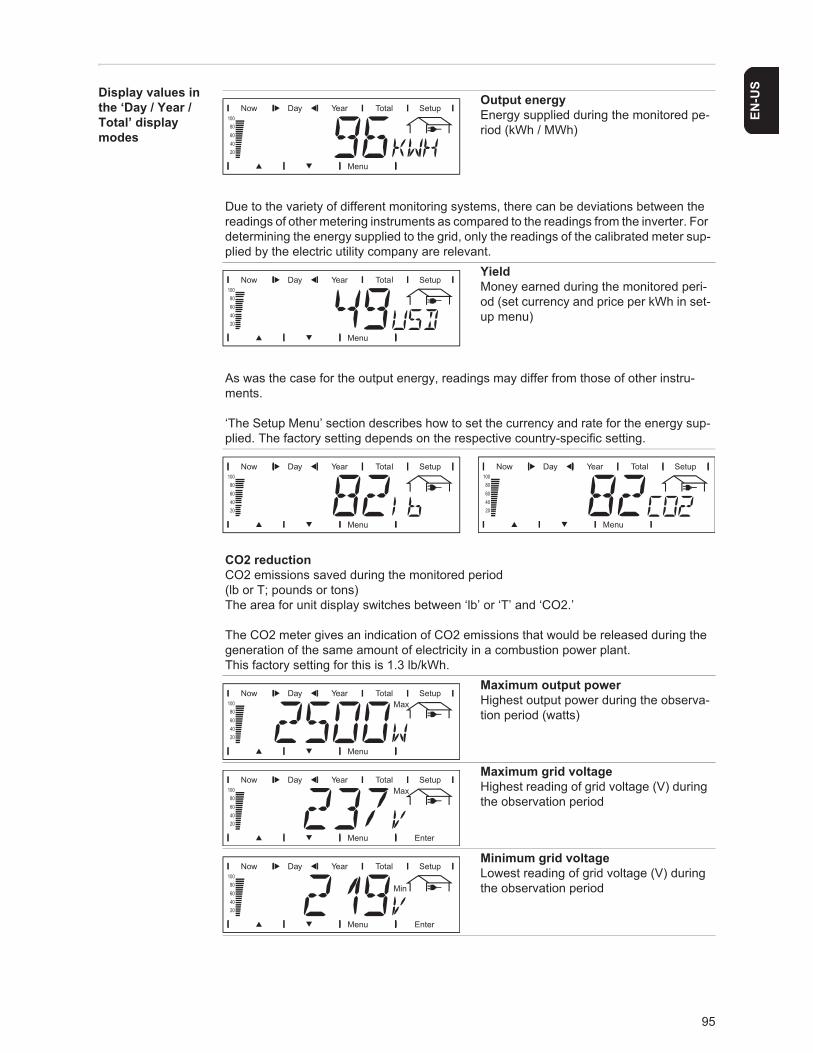
95
EN-U
SDisplay values in the ‘Day / Year / Total’ display modes
Output energyEnergy supplied during the monitored pe-riod (kWh / MWh)
Due to the variety of different monitoring systems, there can be deviations between the readings of other metering instruments as compared to the readings from the inverter. For determining the energy supplied to the grid, only the readings of the calibrated meter sup-plied by the electric utility company are relevant.
YieldMoney earned during the monitored peri-od (set currency and price per kWh in set-up menu)
As was the case for the output energy, readings may differ from those of other instru-ments.
‘The Setup Menu’ section describes how to set the currency and rate for the energy sup-plied. The factory setting depends on the respective country-specific setting.
CO2 reductionCO2 emissions saved during the monitored period(lb or T; pounds or tons)The area for unit display switches between ‘lb’ or ‘T’ and ‘CO2.’
The CO2 meter gives an indication of CO2 emissions that would be released during the generation of the same amount of electricity in a combustion power plant.This factory setting for this is 1.3 lb/kWh.
Maximum output powerHighest output power during the observa-tion period (watts)
Maximum grid voltageHighest reading of grid voltage (V) during the observation period
Minimum grid voltageLowest reading of grid voltage (V) during the observation period
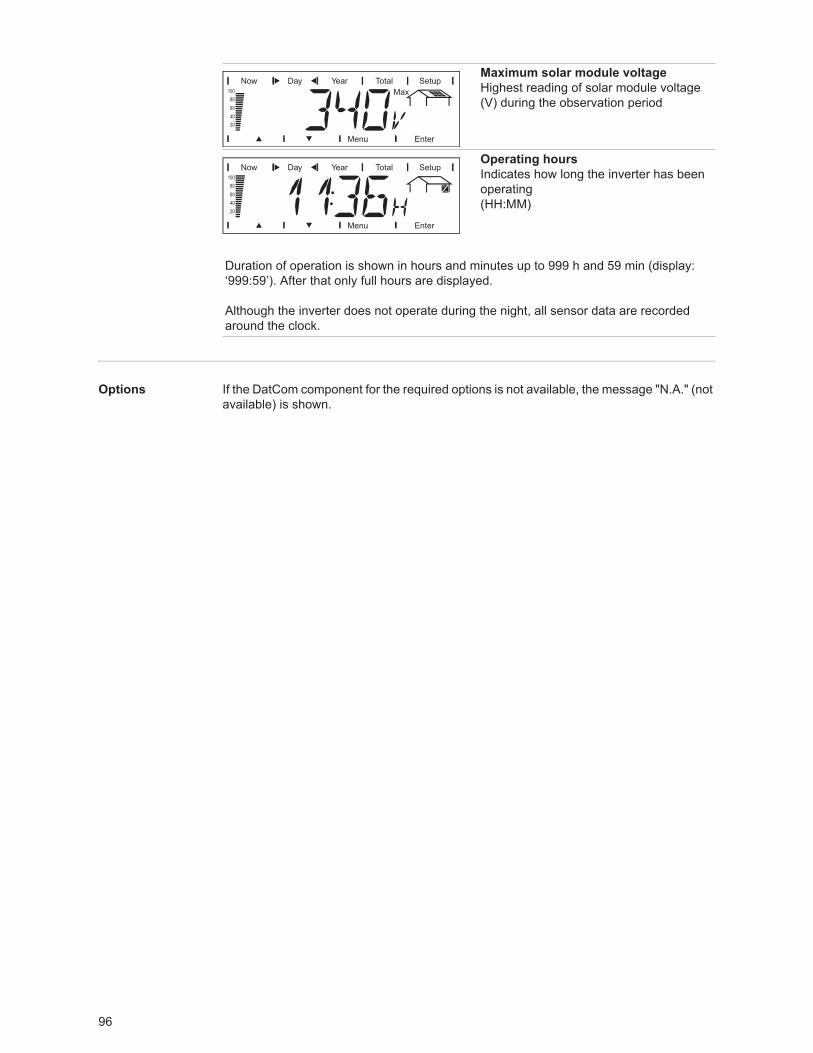
96
Options If the DatCom component for the required options is not available, the message "N.A." (not available) is shown.
Maximum solar module voltageHighest reading of solar module voltage (V) during the observation period
Operating hoursIndicates how long the inverter has been operating(HH:MM)
Duration of operation is shown in hours and minutes up to 999 h and 59 min (display: ‘999:59’). After that only full hours are displayed.
Although the inverter does not operate during the night, all sensor data are recorded around the clock.
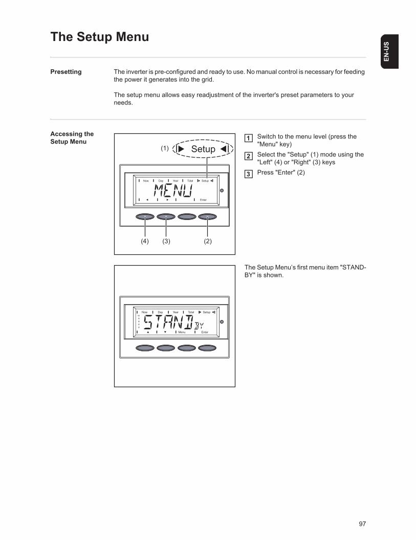
97
EN-U
S
The Setup Menu
Presetting The inverter is pre-configured and ready to use. No manual control is necessary for feeding the power it generates into the grid.
The setup menu allows easy readjustment of the inverter's preset parameters to your needs.
Accessing the Setup Menu
Switch to the menu level (press the "Menu" key)Select the "Setup" (1) mode using the "Left" (4) or "Right" (3) keysPress "Enter" (2)
The Setup Menu’s first menu item "STAND-BY" is shown.
(4) (3) (2)
(1)1
2
3
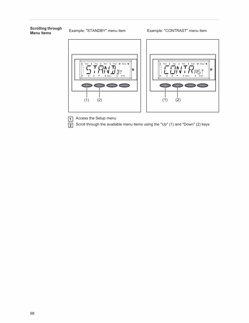
98
Scrolling through Menu Items
Access the Setup menuScroll through the available menu items using the "Up" (1) and "Down" (2) keys
Example: "STANDBY" menu item Example: "CONTRAST" menu item
(1) (2) (1) (2)
12
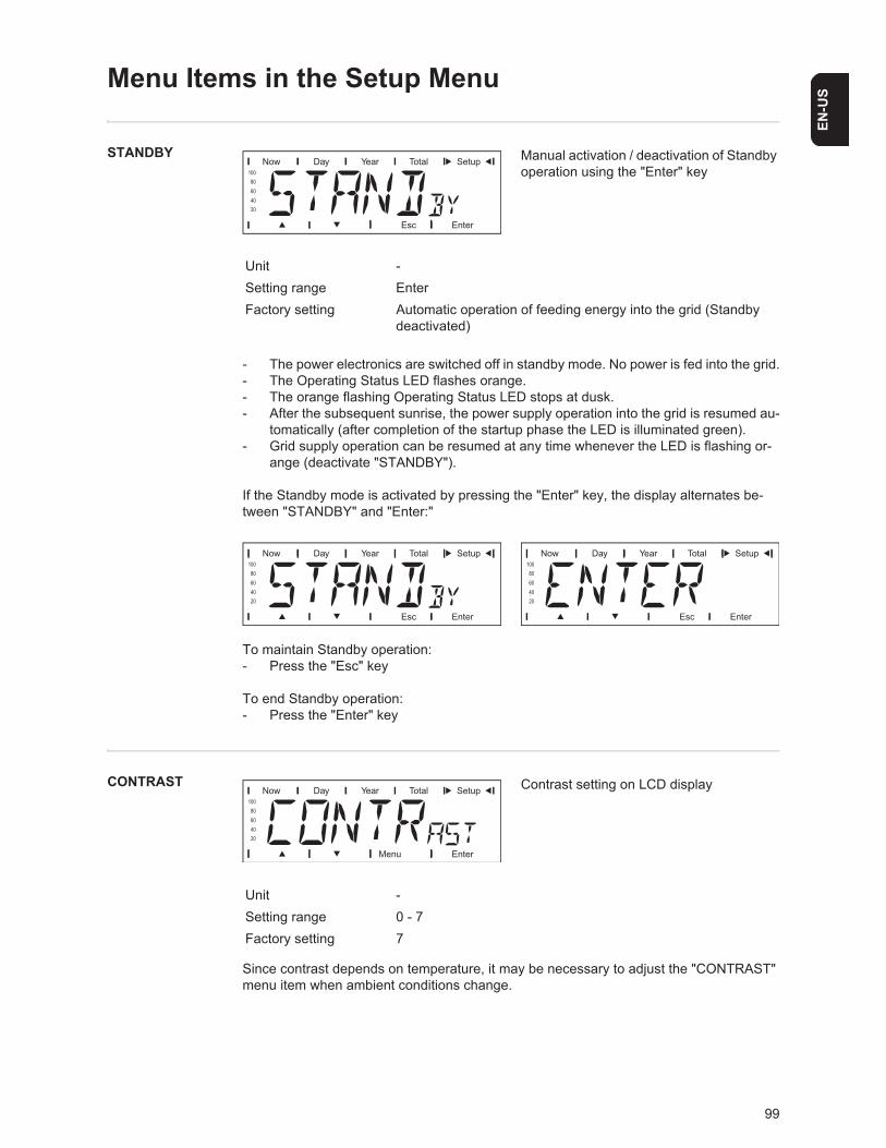
99
EN-U
S
Menu Items in the Setup Menu
STANDBY Manual activation / deactivation of Standby operation using the "Enter" key
- The power electronics are switched off in standby mode. No power is fed into the grid.- The Operating Status LED flashes orange.- The orange flashing Operating Status LED stops at dusk. - After the subsequent sunrise, the power supply operation into the grid is resumed au-
tomatically (after completion of the startup phase the LED is illuminated green).- Grid supply operation can be resumed at any time whenever the LED is flashing or-
ange (deactivate "STANDBY").
If the Standby mode is activated by pressing the "Enter" key, the display alternates be-tween "STANDBY" and "Enter:"
To maintain Standby operation:- Press the "Esc" key
To end Standby operation:- Press the "Enter" key
CONTRAST Contrast setting on LCD display
Since contrast depends on temperature, it may be necessary to adjust the "CONTRAST" menu item when ambient conditions change.
Unit -Setting range EnterFactory setting Automatic operation of feeding energy into the grid (Standby
deactivated)
Unit -Setting range 0 - 7Factory setting 7
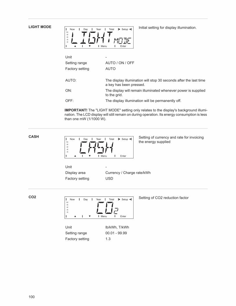
100
LIGHT MODE Initial setting for display illumination.
CASH Setting of currency and rate for invoicing the energy supplied
CO2 Setting of CO2 reduction factor
Unit -Setting range AUTO / ON / OFFFactory setting AUTO
AUTO: The display illumination will stop 30 seconds after the last time a key has been pressed.
ON: The display will remain illuminated whenever power is supplied to the grid.
OFF: The display illumination will be permanently off.
IMPORTANT! The "LIGHT MODE" setting only relates to the display's background illumi-nation. The LCD display will still remain on during operation. Its energy consumption is less than one mW (1/1000 W).
Unit -Display area Currency / Charge rate/kWhFactory setting USD
Unit lb/kWh, T/kWhSetting range 00.01 - 99.99Factory setting 1.3
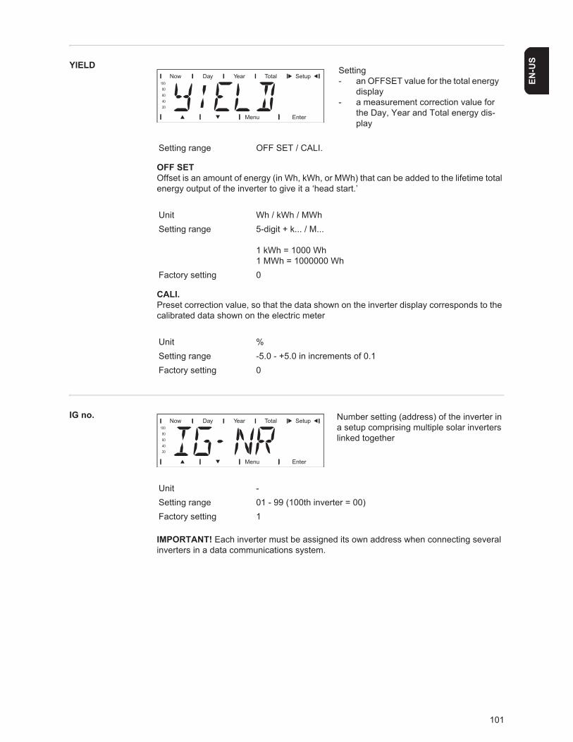
101
EN-U
SYIELD
OFF SETOffset is an amount of energy (in Wh, kWh, or MWh) that can be added to the lifetime total energy output of the inverter to give it a ‘head start.’
CALI.Preset correction value, so that the data shown on the inverter display corresponds to the calibrated data shown on the electric meter
IG no. Number setting (address) of the inverter in a setup comprising multiple solar inverters linked together
Setting- an OFFSET value for the total energy
display - a measurement correction value for
the Day, Year and Total energy dis-play
Setting range OFF SET / CALI.
Unit Wh / kWh / MWhSetting range 5-digit + k... / M...
1 kWh = 1000 Wh1 MWh = 1000000 Wh
Factory setting 0
Unit %Setting range -5.0 - +5.0 in increments of 0.1Factory setting 0
Unit -Setting range 01 - 99 (100th inverter = 00)Factory setting 1
IMPORTANT! Each inverter must be assigned its own address when connecting several inverters in a data communications system.
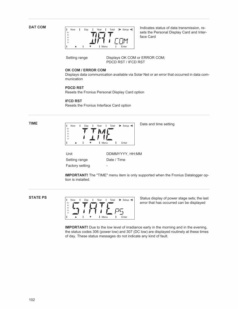
102
DAT COM Indicates status of data transmission, re-sets the Personal Display Card and Inter-face Card
OK COM / ERROR COMDisplays data communication available via Solar Net or an error that occurred in data com-munication
PDCD RSTResets the Fronius Personal Display Card option
IFCD RSTResets the Fronius Interface Card option
TIME Date and time setting
STATE PS Status display of power stage sets; the last error that has occurred can be displayed
Setting range Displays OK COM or ERROR COM; PDCD RST / IFCD RST
Unit DDMMYYYY, HH:MMSetting range Date / TimeFactory setting -
IMPORTANT! The "TIME" menu item is only supported when the Fronius Datalogger op-tion is installed.
IMPORTANT! Due to the low level of irradiance early in the morning and in the evening, the status codes 306 (power low) and 307 (DC low) are displayed routinely at these times of day. These status messages do not indicate any kind of fault.
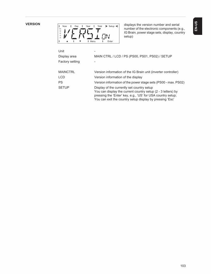
103
EN-U
SVERSION displays the version number and serial number of the electronic components (e.g., IG Brain, power stage sets, display, country setup)
Unit -Display area MAIN CTRL / LCD / PS (PS00, PS01, PS02) / SETUPFactory setting -
MAINCTRL Version information of the IG Brain unit (inverter controller)LCD Version information of the displayPS Version information of the power stage sets (PS00 - max. PS02)SETUP Display of the currently set country setup
You can display the current country setup (2 - 3 letters) by pressing the ‘Enter’ key, e.g., ‘US’ for USA country setup;You can exit the country setup display by pressing ‘Esc’
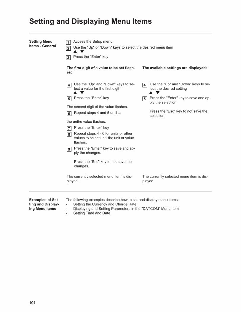
104
Setting and Displaying Menu Items
Setting Menu Items - General
Access the Setup menuUse the "Up" or "Down" keys to select the desired menu item
Press the "Enter" key
Examples of Set-ting and Display-ing Menu Items
The following examples describe how to set and display menu items:- Setting the Currency and Charge Rate- Displaying and Setting Parameters in the "DATCOM" Menu Item- Setting Time and Date
The first digit of a value to be set flash-es:
The available settings are displayed:
Use the "Up" and "Down" keys to se-lect a value for the first digit
Press the "Enter" key
The second digit of the value flashes.Repeat steps 4 and 5 until ...
the entire value flashes.Press the "Enter" keyRepeat steps 4 - 6 for units or other values to be set until the unit or value flashes.Press the "Enter" key to save and ap-ply the changes.
Press the "Esc" key to not save the changes.
Use the "Up" and "Down" keys to se-lect the desired setting
Press the "Enter" key to save and ap-ply the selection.
Press the "Esc" key to not save the selection.
The currently selected menu item is dis-played.
The currently selected menu item is dis-played.
12
3
4
5
6
78
9
4
5
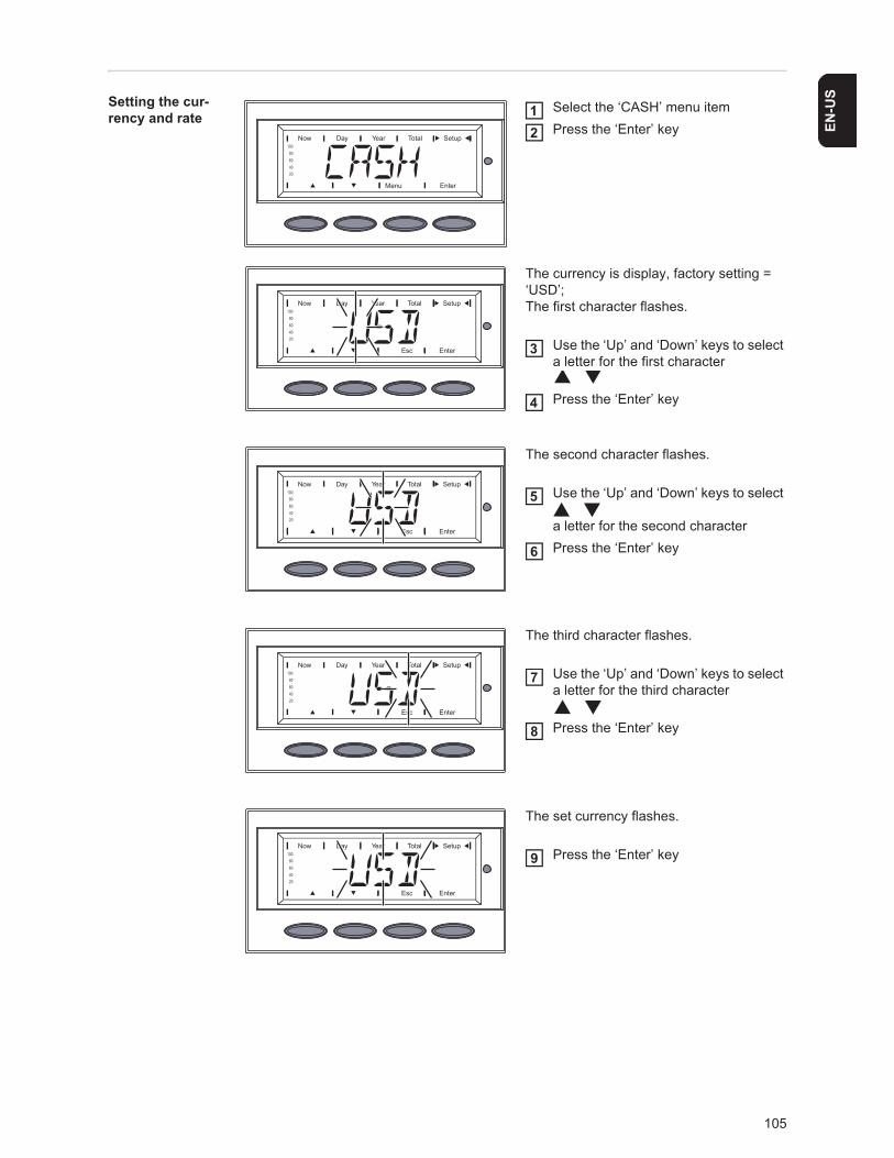
105
EN-U
SSetting the cur-rency and rate
Select the ‘CASH’ menu itemPress the ‘Enter’ key
The currency is display, factory setting = ‘USD’;The first character flashes.
Use the ‘Up’ and ‘Down’ keys to select a letter for the first character
Press the ‘Enter’ key
The second character flashes.
Use the ‘Up’ and ‘Down’ keys to select
a letter for the second characterPress the ‘Enter’ key
The third character flashes.
Use the ‘Up’ and ‘Down’ keys to select a letter for the third character
Press the ‘Enter’ key
The set currency flashes.
Press the ‘Enter’ key
12
3
4
5
6
7
8
9
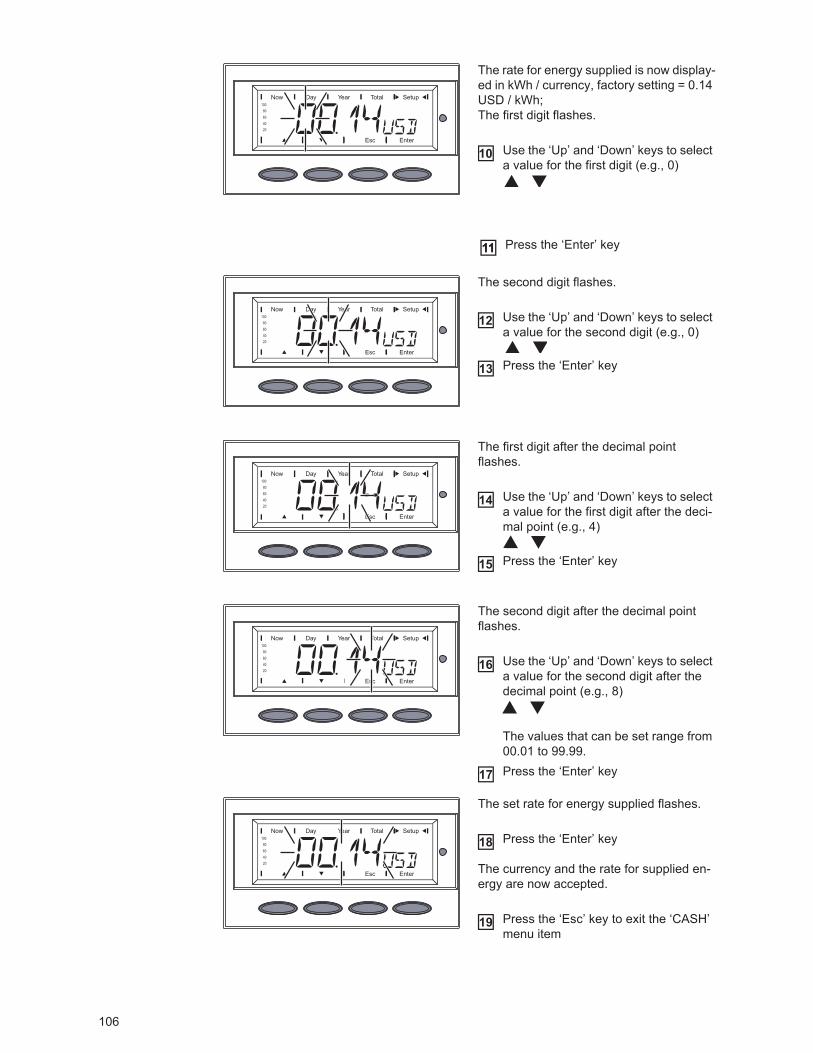
106
The rate for energy supplied is now display-ed in kWh / currency, factory setting = 0.14 USD / kWh;The first digit flashes.
Use the ‘Up’ and ‘Down’ keys to select a value for the first digit (e.g., 0)
The second digit flashes.
Use the ‘Up’ and ‘Down’ keys to select a value for the second digit (e.g., 0)
Press the ‘Enter’ key
The first digit after the decimal point flashes.
Use the ‘Up’ and ‘Down’ keys to select a value for the first digit after the deci-mal point (e.g., 4)
Press the ‘Enter’ key
The second digit after the decimal point flashes.
Use the ‘Up’ and ‘Down’ keys to select a value for the second digit after the decimal point (e.g., 8)
The values that can be set range from 00.01 to 99.99.Press the ‘Enter’ key
The set rate for energy supplied flashes.
Press the ‘Enter’ key
The currency and the rate for supplied en-ergy are now accepted.
Press the ‘Esc’ key to exit the ‘CASH’ menu item
10
Press the ‘Enter’ key1111
12
13
14
15
16
17
18
19
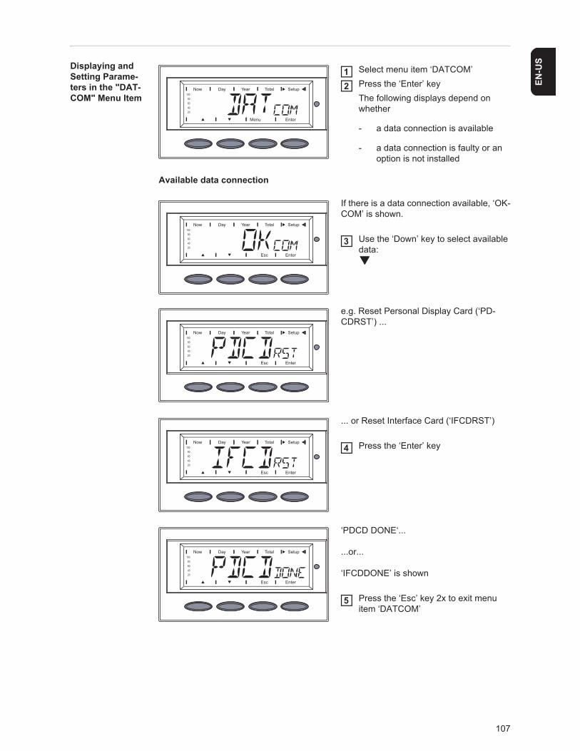
107
EN-U
SDisplaying and Setting Parame-ters in the "DAT-COM" Menu Item
Select menu item ‘DATCOM’Press the ‘Enter’ keyThe following displays depend on whether
- a data connection is available
- a data connection is faulty or an option is not installed
Available data connection
If there is a data connection available, ‘OK-COM’ is shown.
Use the ‘Down’ key to select available data:
e.g. Reset Personal Display Card (‘PD-CDRST’) ...
... or Reset Interface Card (‘IFCDRST’)
Press the ‘Enter’ key
‘PDCD DONE‘...
...or...
‘IFCDDONE’ is shown
Press the ‘Esc’ key 2x to exit menu item ‘DATCOM’
12
3
4
5
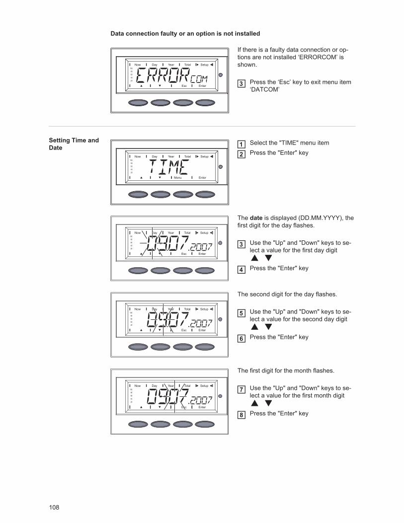
108
Data connection faulty or an option is not installed
If there is a faulty data connection or op-tions are not installed ‘ERRORCOM’ is shown.
Press the ‘Esc’ key to exit menu item ‘DATCOM’
Setting Time and Date
Select the "TIME" menu itemPress the "Enter" key
The date is displayed (DD.MM.YYYY), the first digit for the day flashes.
Use the "Up" and "Down" keys to se-lect a value for the first day digit
Press the "Enter" key
The second digit for the day flashes.
Use the "Up" and "Down" keys to se-lect a value for the second day digit
Press the "Enter" key
The first digit for the month flashes.
Use the "Up" and "Down" keys to se-lect a value for the first month digit
Press the "Enter" key
3
12
3
4
5
6
7
8
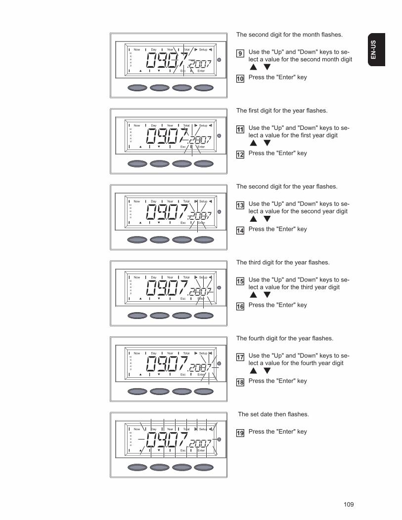
109
EN-U
S
The second digit for the month flashes.
Use the "Up" and "Down" keys to se-lect a value for the second month digit
Press the "Enter" key
The first digit for the year flashes.
Use the "Up" and "Down" keys to se-lect a value for the first year digit
Press the "Enter" key
The second digit for the year flashes.
Use the "Up" and "Down" keys to se-lect a value for the second year digit
Press the "Enter" key
The third digit for the year flashes.
Use the "Up" and "Down" keys to se-lect a value for the third year digit
Press the "Enter" key
The fourth digit for the year flashes.
Use the "Up" and "Down" keys to se-lect a value for the fourth year digit
Press the "Enter" key
The set date then flashes.
Press the "Enter" key
9
10
1111
12
13
14
15
16
17
18
19
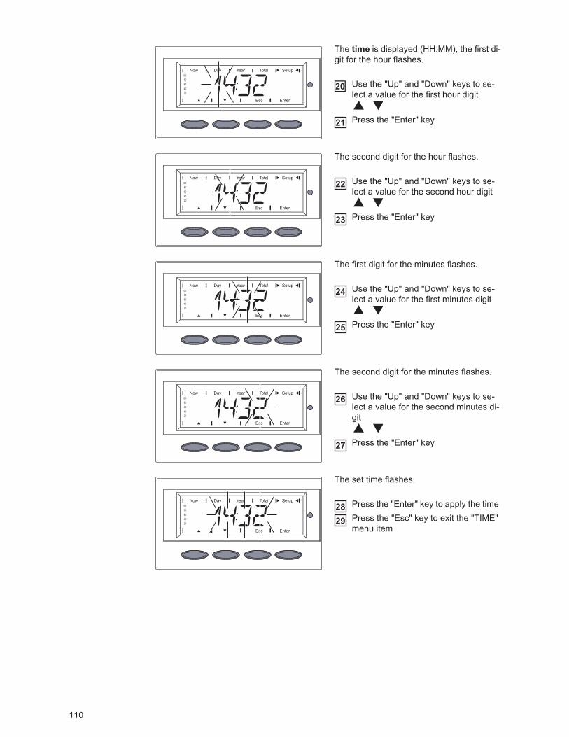
110
The time is displayed (HH:MM), the first di-git for the hour flashes.
Use the "Up" and "Down" keys to se-lect a value for the first hour digit
Press the "Enter" key
The second digit for the hour flashes.
Use the "Up" and "Down" keys to se-lect a value for the second hour digit
Press the "Enter" key
The first digit for the minutes flashes.
Use the "Up" and "Down" keys to se-lect a value for the first minutes digit
Press the "Enter" key
The second digit for the minutes flashes.
Use the "Up" and "Down" keys to se-lect a value for the second minutes di-git
Press the "Enter" key
The set time flashes.
Press the "Enter" key to apply the time Press the "Esc" key to exit the "TIME" menu item
20
21
22
23
24
25
26
27
2829
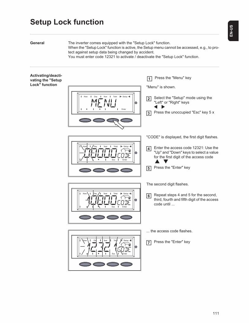
111
EN-U
S
Setup Lock function
General The inverter comes equipped with the "Setup Lock" function. When the "Setup Lock" function is active, the Setup menu cannot be accessed, e.g., to pro-tect against setup data being changed by accident.You must enter code 12321 to activate / deactivate the "Setup Lock" function.
Activating/deacti-vating the "Setup Lock" function "Menu" is shown.
Select the "Setup" mode using the "Left" or "Right" keys
Press the unoccupied "Esc" key 5 x
"CODE" is displayed, the first digit flashes.
Enter the access code 12321: Use the "Up" and "Down" keys to select a value for the first digit of the access code
Press the "Enter" key
The second digit flashes.
Repeat steps 4 and 5 for the second, third, fourth and fifth digit of the access code until ...
... the access code flashes.
Press the "Enter" key
Press the "Menu" key1
2
3
4
5
6
7
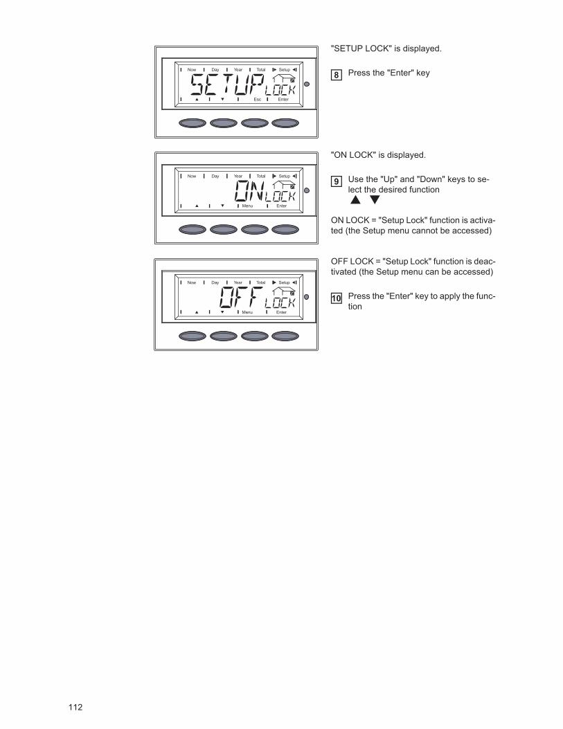
112
"SETUP LOCK" is displayed.
Press the "Enter" key
"ON LOCK" is displayed.
Use the "Up" and "Down" keys to se-lect the desired function
ON LOCK = "Setup Lock" function is activa-ted (the Setup menu cannot be accessed)
OFF LOCK = "Setup Lock" function is deac-tivated (the Setup menu can be accessed)
Press the "Enter" key to apply the func-tion
8
9
10
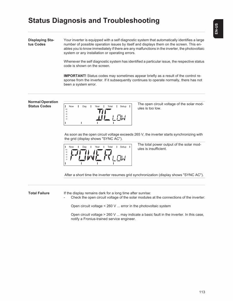
113
EN-U
S
Status Diagnosis and Troubleshooting
Displaying Sta-tus Codes
Your inverter is equipped with a self diagnostic system that automatically identifies a large number of possible operation issues by itself and displays them on the screen. This en-ables you to know immediately if there are any malfunctions in the inverter, the photovoltaic system or any installation or operating errors.
Whenever the self diagnostic system has identified a particular issue, the respective status code is shown on the screen.
Normal Operation Status Codes
Total Failure If the display remains dark for a long time after sunrise:- Check the open circuit voltage of the solar modules at the connections of the inverter:
Open circuit voltage < 260 V ... error in the photovoltaic system
Open circuit voltage > 260 V ... may indicate a basic fault in the inverter. In this case, notify a Fronius-trained service engineer.
IMPORTANT! Status codes may sometimes appear briefly as a result of the control re-sponse from the inverter. If it subsequently continues to operate normally, there has not been a system error.
The open circuit voltage of the solar mod-ules is too low.
As soon as the open circuit voltage exceeds 265 V, the inverter starts synchronizing with the grid (display shows "SYNC AC").
The total power output of the solar mod-ules is insufficient.
After a short time the inverter resumes grid synchronization (display shows "SYNC AC").
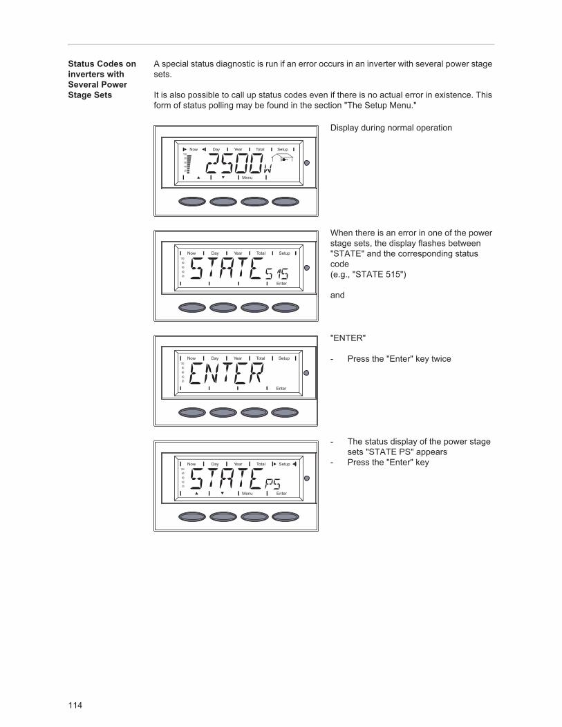
114
Status Codes on inverters with Several Power Stage Sets
A special status diagnostic is run if an error occurs in an inverter with several power stage sets.
It is also possible to call up status codes even if there is no actual error in existence. This form of status polling may be found in the section "The Setup Menu."
Display during normal operation
When there is an error in one of the power stage sets, the display flashes between "STATE" and the corresponding status code(e.g., "STATE 515")
and
"ENTER"
- Press the "Enter" key twice
- The status display of the power stage sets "STATE PS" appears
- Press the "Enter" key
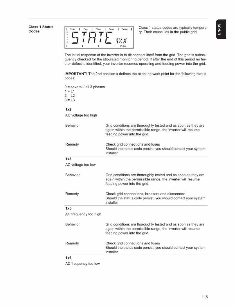
115
EN-U
SClass 1 Status Codes
Class 1 status codes are typically tempora-ry. Their cause lies in the public grid.
The initial response of the inverter is to disconnect itself from the grid. The grid is subse-quently checked for the stipulated monitoring period. If after the end of this period no fur-ther defect is identified, your inverter resumes operating and feeding power into the grid.
IMPORTANT! The 2nd position x defines the exact network point for the following status codes:
0 = several / all 3 phases1 = L12 = L23 = L3
1x2AC voltage too high
Behavior Grid conditions are thoroughly tested and as soon as they are again within the permissible range, the inverter will resume feeding power into the grid.
Remedy Check grid connections and fusesShould the status code persist, you should contact your system installer
1x3AC voltage too low
Behavior Grid conditions are thoroughly tested and as soon as they are again within the permissible range, the inverter will resume feeding power into the grid.
Remedy Check grid connections, breakers and disconnectShould the status code persist, you should contact your system installer
1x5AC frequency too high
Behavior Grid conditions are thoroughly tested and as soon as they are again within the permissible range, the inverter will resume feeding power into the grid.
Remedy Check grid connections and fusesShould the status code persist, you should contact your system installer
1x6AC frequency too low
116
Behavior Grid conditions are thoroughly tested and as soon as they are again within the permissible range, the inverter will resume feeding power into the grid.
Remedy Check grid connections and fusesShould the status code persist, you should contact your system installer
1x7No AC grid detected
Behavior Grid conditions are thoroughly tested and as soon as they are again within the permissible range, the inverter will resume feeding power into the grid.
Remedy Check grid connections and fusesShould the status code persist, you should contact your system installer
108Islanding detected
Behavior Grid conditions are thoroughly tested and as soon as they are again within the permissible range, the inverter will resume feeding power into the grid.
Remedy Should the status code persist, you should contact your system installer
109General grid errorThis error is always displayed first for grid errors. After reviewing all power stage sets, the grid error is specified in more detail: 1x1 / 1x4 or the display remains at "109" (e.g., when 2 phases report "104" and one phase "101")
Behavior Grid conditions are thoroughly tested and as soon as they are again within the permissible range, the inverter will resume feeding power into the grid.
Remedy Check grid connections and fusesShould the status code persist, you should contact your system installer
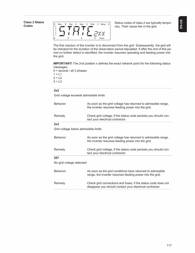
117
EN-U
SClass 2 Status Codes
Status codes of class 2 are typically tempo-rary. Their cause lies in the grid.
The first reaction of the inverter is to disconnect from the grid. Subsequently, the grid will be checked for the duration of the observation period stipulated. If after the end of this pe-riod no further defect is identified, the inverter resumes operating and feeding power into the grid.
IMPORTANT! The 2nd position x defines the exact network point for the following status messages:0 = several / all 3 phases1 = L12 = L23 = L3
2x2Grid voltage exceeds admissible limits
Behavior As soon as the grid voltage has returned to admissible range, the inverter resumes feeding power into the grid.
Remedy Check grid voltage; if the status code persists you should con-tact your electrical contractor
2x3Grid voltage below admissible limits
Behavior As soon as the grid voltage has returned to admissible range, the inverter resumes feeding power into the grid.
Remedy Check grid voltage, if the status code persists you should con-tact your electrical contractor
207No grid voltage detected
Behavior As soon as the grid conditions have returned to admissible range, the inverter resumes feeding power into the grid.
Remedy Check grid connections and fuses; if the status code does not disappear you should contact your electrical contractor
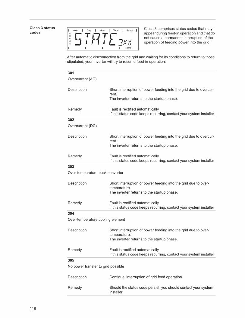
118
Class 3 status codes
Class 3 comprises status codes that may appear during feed-in operation and that do not cause a permanent interruption of the operation of feeding power into the grid.
After automatic disconnection from the grid and waiting for its conditions to return to those stipulated, your inverter will try to resume feed-in operation.
301Overcurrent (AC)
Description Short interruption of power feeding into the grid due to overcur-rent.The inverter returns to the startup phase.
Remedy Fault is rectified automaticallyIf this status code keeps recurring, contact your system installer
302Overcurrent (DC)
Description Short interruption of power feeding into the grid due to overcur-rent.The inverter returns to the startup phase.
Remedy Fault is rectified automaticallyIf this status code keeps recurring, contact your system installer
303Over-temperature buck converter
Description Short interruption of power feeding into the grid due to over-temperature.The inverter returns to the startup phase.
Remedy Fault is rectified automaticallyIf this status code keeps recurring, contact your system installer
304Over-temperature cooling element
Description Short interruption of power feeding into the grid due to over-temperature.The inverter returns to the startup phase.
Remedy Fault is rectified automaticallyIf this status code keeps recurring, contact your system installer
305No power transfer to grid possible
Description Continual interruption of grid feed operation
Remedy Should the status code persist, you should contact your system installer
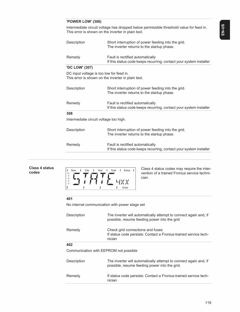
119
EN-U
S
Class 4 status codes
Class 4 status codes may require the inter-vention of a trained Fronius service techni-cian.
'POWER LOW' (306)Intermediate circuit voltage has dropped below permissible threshold value for feed in.This error is shown on the inverter in plain text.
Description Short interruption of power feeding into the grid.The inverter returns to the startup phase.
Remedy Fault is rectified automaticallyIf this status code keeps recurring, contact your system installer
'DC LOW' (307)DC input voltage is too low for feed in.This error is shown on the inverter in plain text.
Description Short interruption of power feeding into the grid.The inverter returns to the startup phase.
Remedy Fault is rectified automaticallyIf this status code keeps recurring, contact your system installer
308Intermediate circuit voltage too high.
Description Short interruption of power feeding into the grid.The inverter returns to the startup phase.
Remedy Fault is rectified automaticallyIf this status code keeps recurring, contact your system installer
401No internal communication with power stage set
Description The inverter will automatically attempt to connect again and, if possible, resume feeding power into the grid
Remedy Check grid connections and fusesIf status code persists: Contact a Fronius-trained service tech-nician
402Communication with EEPROM not possible
Description The inverter will automatically attempt to connect again and, if possible, resume feeding power into the grid.
Remedy If status code persists: Contact a Fronius-trained service tech-nician
120
403EEPROM faulty
Description The inverter will automatically attempt to connect again and, if possible, resume feeding power into the grid.
Remedy If status code persists: Contact a Fronius-trained service tech-nician
406One or both temperature sensors are defective
Description The inverter disconnects from the grid for safety reasons.
Remedy If status code persists: Contact a Fronius-trained service tech-nician
407Temperature sensor at cooling element defective
Description The inverter disconnects from the grid for safety reasons.
Remedy If status code persists: Contact a Fronius-trained service tech-nician
408Direct current feed in
Description The inverter disconnects from the grid for safety reasons.
Remedy If status code persists: Contact a Fronius-trained service tech-nician
412The "fixed voltage" setting has been selected instead of MPP voltage operation and the voltage is set to too low a value, or DC voltage exceeds allowable limits.
Description Fixed voltage lower than the current MPP voltage.
Remedy If the status code persists, you should contact a Fronius-trained service technician, or remove excess solar modules so DC volt-age fits within inverter limits.If status code persists: Contact a Fronius-trained service tech-nician
413Control problems
Description The inverter briefly disconnects from the grid, if AC voltage or frequency are out of range.
Remedy If status code persists: Contact a Fronius-trained service tech-nician
414EEPROM faulty
121
EN-U
S
Description Memory deleted
Remedy If status code persists: Contact a Fronius-trained service tech-nician
416Communication with IG Brain not possible.
Description The Operating Status LED lights up orange, then the inverter at-tempts a restart.
Remedy If status code persists: Contact a Fronius-trained service tech-nician
417Two power stage sets have the same PCB number
Description The inverter stops feeding power into the grid, the display shows a critical error via a red Operating Status LED
Remedy If status code persists: Contact a Fronius-trained service tech-nician
419Two or more power stage sets with an identical software serial number detected.
Description The inverter stops feeding power into the grid, the display shows a critical error via a red Operating Status LED
Remedy If status code persists: Contact a Fronius-trained service tech-nician
421PCB number has been set incorrectly
Description The inverter stops feeding power into the grid, the display shows a critical error via a red Operating Status LED.
Remedy If status code persists: Contact a Fronius-trained service tech-nician
425Communication with the power stage set is not possible
Description The Operating Status LED lights up orange, then the inverter at-tempts a restart.
Remedy If status code persists: Contact a Fronius-trained service tech-nician
431All power stage sets are in boot mode
Description The inverter stops feeding power into the grid, the display shows a critical error via a red Operating Status LED.
Remedy Update firmware using Bootloader or Fronius Solar.update/IG Plus
122
Switches between SLAVE / DC LOW or SLAVE / POWER LOW (439)The MPP master power stage set is switched off because of an error in a slave power stage set (in the balance mode).
Description The inverter stops feeding power into the grid, the display shows a critical error via a red Operating Status LED.
Remedy If status code persists: Contact a Fronius-trained service tech-nician
Switches between SLAVE / DC LOW or SLAVE / POWER LOW (439)The MPP master power stage set is switched off because of a fauilty GFDI fuse.
Description The inverter stops feeding power into the grid, the display shows a critical error via a red Operating Status LED.
Remedy Check the GFDI fuse and replace it, if necessary. If status code persists: Contact a Fronius-trained service tech-nician
442No phase master for a phase
Description The inverter stops feeding power into the grid, the display shows a critical error via a red Operating Status LED.
Remedy If status code persists: Contact a Fronius-trained service tech-nician
443Energy transfer not possible
Description The inverter stops feeding power into the grid, the display shows a critical error via a red Operating Status LED.
Remedy If status code persists: Contact a Fronius-trained service tech-nician
445Invalid power stage set configuration
Description The inverter stops feeding power into the grid, the display shows a critical error via a red Operating Status LED.
Remedy If status code persists: Contact a Fronius-trained service tech-nician
446Internal communication error with the NL-MON plug-in card
Description The inverter will automatically attempt to connect again and, if possible, resume feeding power into the grid
Remedy Check grid connections and fuses;If status code persists: Contact a Fronius-trained service tech-nician
123
EN-U
S
447The NL-MON plug-in card has interrupted grid monitoring
Description The inverter will automatically attempt to connect again and, if possible, resume feeding power into the grid
Remedy If status code persists: Contact a Fronius-trained service tech-nician
448The neutral conductor N is not connected
Description The inverter disconnects from the grid for safety reasons.
Remedy If status code persists: Contact a Fronius-trained service tech-nician
450The monitoring of the power stage set main processor ‘Guard’ is active
Description The inverter stops feeding power into the grid, the display shows a critical error via a red Operating Status LED.
Remedy If status code persists: Contact a Fronius-trained service tech-nician
451The EEPROM Guard Control is defective
Description The inverter stops feeding power into the grid, the display shows a critical error via a red Operating Status LED.
Remedy If status code persists: Contact a Fronius-trained service tech-nician
452Communication between ‘Guard’ and the digital signal processor (DSP) has been inter-rupted
Description The inverter stops feeding power into the grid, the display shows a critical error via a red Operating Status LED.
Remedy If status code persists: Contact a Fronius-trained service tech-nician
453Error in grid voltage recording
Description The inverter stops feeding power into the grid, the display shows a critical error via a red Operating Status LED.
Remedy If status code persists: Contact a Fronius-trained service tech-nician
454Error in grid frequency recording
124
Description The inverter stops feeding power into the grid, the display shows a critical error via a red Operating Status LED.
Remedy If status code persists: Contact a Fronius-trained service tech-nician
455Reference power source for AC measurement is operating outside of tolerances
Description The inverter stops feeding power into the grid, the display shows a critical error via a red Operating Status LED.
Remedy If status code persists: Contact a Fronius-trained service tech-nician
456Error during anti-islanding test
Description The inverter stops feeding power into the grid, the display shows a critical error via a red Operating Status LED.
Remedy If status code persists: Contact a Fronius-trained service tech-nician
457Grid relay stuck
Description The inverter stops feeding power into the grid, the display shows a critical error via a red Operating Status LED.
Remedy If status code persists: Contact a Fronius-trained service tech-nician
460Reference power source for the digital signal processor (DSP) is operating outside of tol-erances
Description The inverter stops feeding power into the grid, the display shows a critical error via a red Operating Status LED.
Remedy If status code persists: Contact a Fronius-trained service tech-nician
461Error in DSP data memory
Description The inverter stops feeding power into the grid, the display shows a critical error via a red Operating Status LED.
Remedy If status code persists: Contact a Fronius-trained service tech-nician
464Display errorThe software and/or hardware versions of the display and IG Brain are not compatible.
Description The inverter stops feeding power into the grid, the display shows a critical error via a red Operating Status LED.
125
EN-U
S
Remedy Update firmware using Bootloader or Fronius Solar.update/IG Plus
465Display errorThe UI command sent from the IG Brain is not recognized by the present display version.
Description The inverter stops feeding power into the grid, the display shows a critical error via a red Operating Status LED.
Remedy If status code persists: Contact a Fronius-trained service tech-nician
466Display errorThe display was not detected.
Description The inverter stops feeding power into the grid, the display shows a critical error via a red Operating Status LED.
Remedy Check the display for damage, connect display, check ribbon wire for damage, check IG Brain for damageIf status code persists: Contact a Fronius-trained service tech-nician
467The display has not received a start command from the IG Brain for longer than 6 s.
Description The inverter will automatically attempt to connect again and, if possible, resume feeding power into the grid.
Remedy If status code persists: Contact a Fronius-trained service tech-nician
469Throttle connected to wrong poles
Description The inverter stops feeding power into the grid, the display shows a critical error via a red Operating Status LED.
Remedy Properly connect throttleIf status code persists: Contact a Fronius-trained service tech-nician
470The buck converter relay does not open at high DC voltage
Description The inverter stops feeding power into the grid, the display shows a critical error via a red Operating Status LED.
Remedy Check system configurationIf status code persists: Contact a Fronius-trained service tech-nician
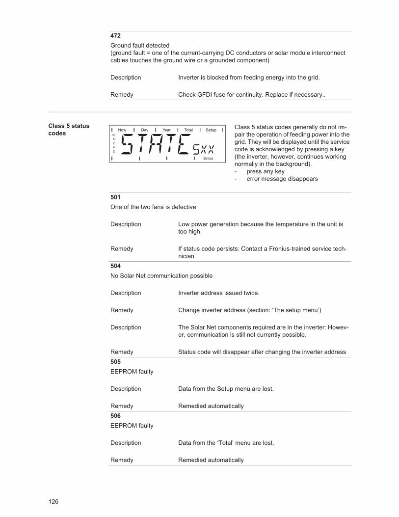
126
Class 5 status codes
Class 5 status codes generally do not im-pair the operation of feeding power into the grid. They will be displayed until the service code is acknowledged by pressing a key (the inverter, however, continues working normally in the background).- press any key- error message disappears
472Ground fault detected(ground fault = one of the current-carrying DC conductors or solar module interconnect cables touches the ground wire or a grounded component)
Description Inverter is blocked from feeding energy into the grid.
Remedy Check GFDI fuse for continuity. Replace if necessary..
501One of the two fans is defective
Description Low power generation because the temperature in the unit is too high.
Remedy If status code persists: Contact a Fronius-trained service tech-nician
504No Solar Net communication possible
Description Inverter address issued twice.
Remedy Change inverter address (section: ‘The setup menu’)
Description The Solar Net components required are in the inverter: Howev-er, communication is still not currently possible.
Remedy Status code will disappear after changing the inverter address505EEPROM faulty
Description Data from the Setup menu are lost.
Remedy Remedied automatically506EEPROM faulty
Description Data from the ‘Total’ menu are lost.
Remedy Remedied automatically
127
EN-U
S
507EEPROM faulty
Description Data from the ‘Day’ / ‘Year’ menu are lost.
Remedy Remedied automatically508Inverter address incorrect
Description Address for data communication is no longer saved.
Remedy Set address again50924h no feed in
Description Example: solar modules covered with snow
Remedy Example: remove snow from solar modules510EEPROM faulty
Description SMS settings were restored to default.
Remedy If necessary, reconfigure SMS511EEPROM faulty
Description Sensor card settings were restored to default
Remedy If necessary, reconfigure metering channels512Too many power stage sets in the system
Description Too many power stage sets have been detected in the system.
Remedy If status code persists: Contact a Fronius-trained service tech-nician
513Power stage set in boot mode
Description One or more power stage sets cannot be activated, because they are in boot mode.
Remedy Update power stage set firmware
128
514No communication with one of the power stage sets
Description Warning message from one of the power stage sets, second power stage set working normally
Remedy If status code persists: Contact a Fronius-trained service tech-nician
515Faulty plug connections
Description Temperature sensor on cooling element faulty or not connected properly.
Remedy If status code persists: Contact a Fronius-trained service tech-nician
516Status codes present for one of the power stage sets.
Description It is not possible to activate all power stage sets
Remedy Carry out analysis. For more information, see the ‘The setup menu’ section. If status code persists: Contact a Fronius-trained service technician
517Change of master has taken place.
Description Transformer not connected / not plugged inBridge short-circuitDetection of intermediate circuit voltage damaged
Remedy Check possible errors referred to in ‘Description.’ If status code persists: Contact a Fronius-trained service technician
550String fuse defective.
Description One or more string fuses are defective.
Remedy Measure string fuses and replace any that are defective550Jumper set incorrectly
Description The jumper on the C-Box PC board was not reset to the ‘SMon’ position after the solar module strings were checked
Remedy Set the jumper on the C-Box PC board to the ‘SMon’ position
129
EN-U
S
Customer Service
553Phase master deactivated due to frequently occurring errors
Description A reintegration of the power stage set into the Mix network will be attempted at a later time.
Remedy If status code persists: Contact a Fronius-trained service tech-nician
554NL-Mon EEPROM error
Description Default set switch off limits were restored automatically.
Remedy System-specific changes in the ‘Advanced’ service menu have to be redone;If status code persists: Contact a Fronius-trained service tech-nician
558Feature deactivated (e.g., inverter control via the Fronius Power Control Box option)
Description A feature had to be deactivated (e.g., after component replace-ment).The status message is no longer displayed after the next DC disconnect.
Remedy Confirm error, update firmware using Bootloader or Fronius So-lar.update/IG Plus, if required(The inverter will also operate problem-free without updating the firmware)
IMPORTANT! Please contact your Fronius dealer or a Fronius-trained service technician if- an error appears frequently or for a long period of time- an error appears that is not listed in the tables
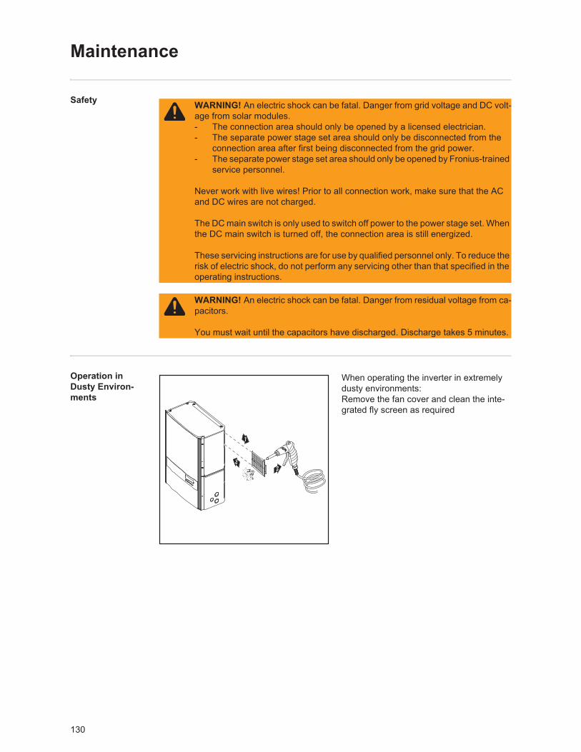
130
Maintenance
Safety
Operation in Dusty Environ-ments
When operating the inverter in extremely dusty environments:Remove the fan cover and clean the inte-grated fly screen as required
WARNING! An electric shock can be fatal. Danger from grid voltage and DC volt-age from solar modules.- The connection area should only be opened by a licensed electrician.- The separate power stage set area should only be disconnected from the
connection area after first being disconnected from the grid power.- The separate power stage set area should only be opened by Fronius-trained
service personnel.
Never work with live wires! Prior to all connection work, make sure that the AC and DC wires are not charged.
The DC main switch is only used to switch off power to the power stage set. When the DC main switch is turned off, the connection area is still energized.
These servicing instructions are for use by qualified personnel only. To reduce the risk of electric shock, do not perform any servicing other than that specified in the operating instructions.
WARNING! An electric shock can be fatal. Danger from residual voltage from ca-pacitors.
You must wait until the capacitors have discharged. Discharge takes 5 minutes.
2
1
3
131
EN-U
SOpening the in-verter for service/maintenance
If the inverter is showing an error code:- press 'enter' to enter the 'setup' menu
If the inverter is running:- press 'menu'- then use left-right arrows to go over to 'setup'- Enter 'setup'- then go down to 'state PS'- Enter 'state PS' & note the status of power stage 00 (e. g. run, standby, or not installed)- Then enter PS 00 & note the last error code
If no error code is stored, three blank lines will be shown.
A single stage inverter (IG Plus 3.0 or 3.8) may now be turned of as below.
For two & three stage inverters:- press 'esc'- use up or down arrow to select power stage set PS 01 and 02 and repeat the process.
These error codes may be useful in troubleshooting and will be erased when the inverter is turned off
Procedure for opening the inverter for service or maintenance:
Disconnect AC and DC supply from the inverterOpen the connection areaTurn off DC main switchAllow the capacitors to discharge (5 minutes)Remove metal coversRemove the plastic dividersRemove string fusesDisconnect DC wiresDisconnect AC wires
NOTE! For troubleshooting, it is useful to measure operating DC and AC voltages and retrieve any stored error codes from each power stage prior to turning off the inverter.
123456789
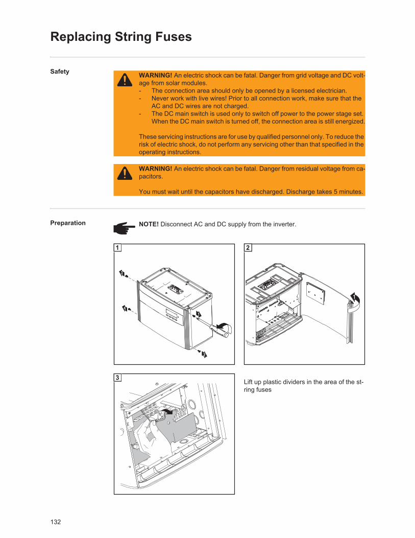
132
Replacing String Fuses
Safety
Preparation
Lift up plastic dividers in the area of the st-ring fuses
WARNING! An electric shock can be fatal. Danger from grid voltage and DC volt-age from solar modules.- The connection area should only be opened by a licensed electrician.- Never work with live wires! Prior to all connection work, make sure that the
AC and DC wires are not charged.- The DC main switch is used only to switch off power to the power stage set.
When the DC main switch is turned off, the connection area is still energized.
These servicing instructions are for use by qualified personnel only. To reduce the risk of electric shock, do not perform any servicing other than that specified in the operating instructions.
WARNING! An electric shock can be fatal. Danger from residual voltage from ca-pacitors.
You must wait until the capacitors have discharged. Discharge takes 5 minutes.
NOTE! Disconnect AC and DC supply from the inverter.
14
2
3
1
1
2
1
3
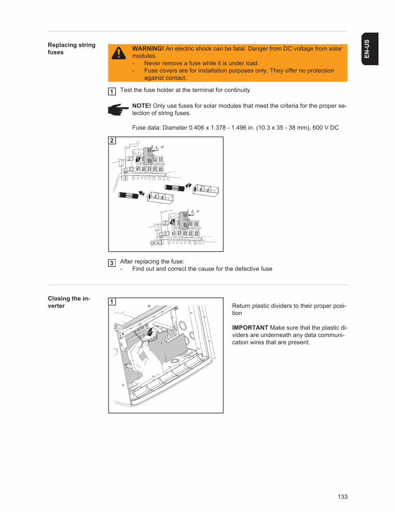
133
EN-U
SReplacing string fuses
Test the fuse holder at the terminal for continuity
After replacing the fuse:- Find out and correct the cause for the defective fuse
Closing the in-verter Return plastic dividers to their proper posi-
tion
IMPORTANT Make sure that the plastic di-viders are underneath any data communi-cation wires that are present.
WARNING! An electric shock can be fatal. Danger from DC voltage from solar modules.- Never remove a fuse while it is under load.- Fuse covers are for installation purposes only. They offer no protection
against contact.
NOTE! Only use fuses for solar modules that meet the criteria for the proper se-lection of string fuses.
Fuse data: Diameter 0.406 x 1.378 - 1.496 in. (10.3 x 35 - 38 mm), 600 V DC
1
4
2
3
1
DC+
2
3
1
1
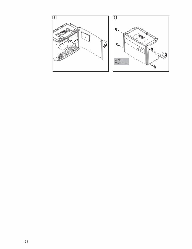
134
1
2
3
2
4 1
3 Nm2.21 ft. lb.
3
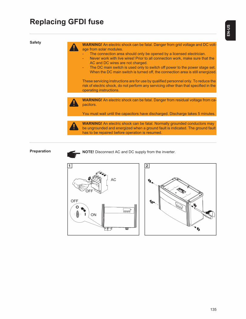
135
EN-U
S
Replacing GFDI fuse
Safety
Preparation
WARNING! An electric shock can be fatal. Danger from grid voltage and DC volt-age from solar modules.- The connection area should only be opened by a licensed electrician.- Never work with live wires! Prior to all connection work, make sure that the
AC and DC wires are not charged.- The DC main switch is used only to switch off power to the power stage set.
When the DC main switch is turned off, the connection area is still energized.
These servicing instructions are for use by qualified personnel only. To reduce the risk of electric shock, do not perform any servicing other than that specified in the operating instructions.
WARNING! An electric shock can be fatal. Danger from residual voltage from ca-pacitors.
You must wait until the capacitors have discharged. Discharge takes 5 minutes.
WARNING! An electric shock can be fatal. Normally grounded conductors may be ungrounded and energized when a ground fault is indicated. The ground fault has to be repaired before operation is resumed.
NOTE! Disconnect AC and DC supply from the inverter.
off
on
1
2
OFF
AC
OFF
ON
1
14
2
3
2
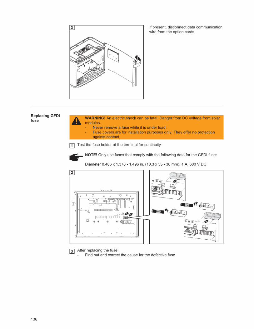
136
If present, disconnect data communication wire from the option cards.
Replacing GFDI fuse
Test the fuse holder at the terminal for continuity
After replacing the fuse:- Find out and correct the cause for the defective fuse
1
3
WARNING! An electric shock can be fatal. Danger from DC voltage from solar modules.- Never remove a fuse while it is under load.- Fuse covers are for installation purposes only. They offer no protection
against contact.
NOTE! Only use fuses that comply with the following data for the GFDI fuse:
Diameter 0.406 x 1.378 - 1.496 in. (10.3 x 35 - 38 mm), 1 A, 600 V DC
1
41
4
1
2
3
2
3
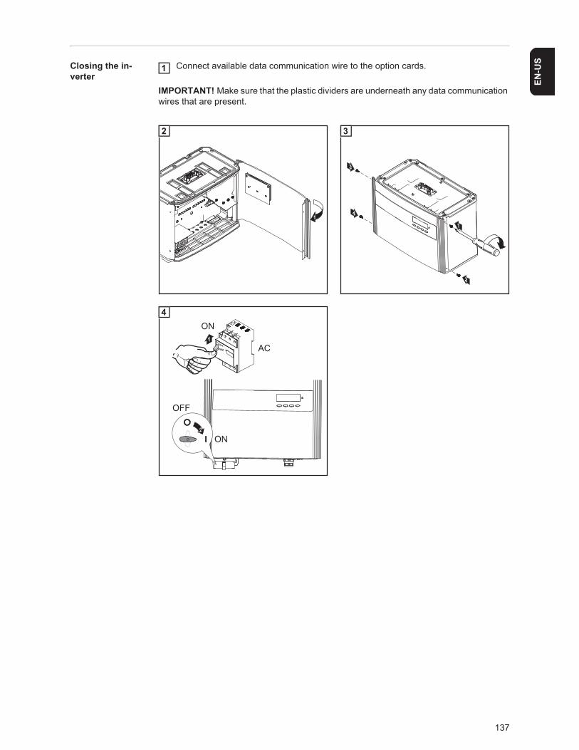
137
EN-U
SClosing the in-verter
Connect available data communication wire to the option cards.
IMPORTANT! Make sure that the plastic dividers are underneath any data communication wires that are present.
1
1
2
3
2
4 1
3
off
on1
ON
AC
2ON
OFF
4
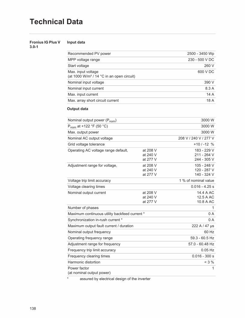
138
Technical Data
Fronius IG Plus V 3.0-1
Input data
Output data
* assured by electrical design of the inverter
Recommended PV power 2500 - 3450 WpMPP voltage range 230 - 500 V DCStart voltage 260 VMax. input voltage(at 1000 W/m² / 14 °C in an open circuit)
600 V DC
Nominal input voltage 390 VNominal input current 8.3 AMax. input current 14 AMax. array short circuit current 18 A
Nominal output power (Pnom) 3000 WPnom at +122 °F (50 °C) 3000 WMax. output power 3000 WNominal AC output voltage 208 V / 240 V / 277 VGrid voltage tolerance +10 / -12 %Operating AC voltage range default, at 208 V
at 240 Vat 277 V
183 - 229 V211 - 264 V244 - 305 V
Adjustment range for voltage, at 208 Vat 240 Vat 277 V
105 - 248 V120 - 287 V140 - 324 V
Voltage trip limit accuracy 1 % of nominal valueVoltage clearing times 0.016 - 4.25 sNominal output current at 208 V
at 240 Vat 277 V
14.4 A AC12.5 A AC10.8 A AC
Number of phases 1Maximum continuous utility backfeed current * 0 ASynchronization in-rush current * 0 AMaximum output fault current / duration 222 A / 47 μsNominal output frequency 60 HzOperating frequency range 59.3 - 60.5 HzAdjustment range for frequency 57.0 - 60.48 HzFrequency trip limit accuracy 0.05 HzFrequency clearing times 0.016 - 300 sHarmonic distortion < 3 %Power factor(at nominal output power)
1

139
EN-U
S
General data
Safety equipment
Maximum efficiency 96.2 %CEC efficiency at 208 V
at 240 Vat 277 V
95.0 %95.5 %95.5 %
Night consumption < 1 WConsumption during operation 8 WCooling Controlled forced ventilationDegree of protection NEMA 3RUnit dimensions w x h x d 17.09 x 24.84 x 9.61 in.
434 x 631 x 244 mmPower stage set weight 31 lbs.
14 kgConnection area weight 24 lbs.
11 kgShipping dimensions w x h x d 20.28 x 31.02 x 14.02 in.
515 x 788 x 356 mmShipping weight 59 lbs.
27 kgPermissible ambient temperature (with 95% rel. humidity)
-13 °F - +131 °F- 25 °C - +55 °C
Permitted storage temperature (with 95% rel. humidity)
-13 °F - +149 °F- 25 °C - +65 °C
Ground fault protection internal GFDI(Ground Fault Detector/Interrupter)
Islanding protection integratedProtection against reverse polarity integratedOver temperature output power derating /
active cooling

140
Fronius IG Plus V 3.8-1
Input data
Output data
* assured by electrical design of the inverter
Recommended PV power 3200 - 4400 WpMPP voltage range 230 - 500 V DCStart voltage 260 VMax. input voltage(at 1000 W/m² / 14 °C in an open circuit)
600 V DC
Nominal input voltage 390 VNominal input current 10.5 AMax. input current 17.8 AMax. array short circuit current 22 A
Nominal output power (Pnom) 3800 WPnom at +122 °F (50 °C) 3800 WMax. output power 3800 WNominal AC output voltage 208 V / 240 V / 277 VGrid voltage tolerance +10 / -12 %Operating AC voltage range default, at 208 V
at 240 Vat 277 V
183 - 229 V211 - 264 V244 - 305 V
Adjustment range for voltage, at 208 Vat 240 Vat 277 V
105 - 248 V120 - 287 V140 - 324 V
Voltage trip limit accuracy 1 % of nominal valueVoltage clearing times 0.016 - 4.25 sNominal output current at 208 V
at 240 Vat 277 V
18.3 A AC15.8 A AC13.7 A AC
Number of phases 1Maximum continuous utility backfeed current * 0 ASynchronization in-rush current * 0 AMaximum output fault current / duration 222 A / 47 μsNominal output frequency 60 HzOperating frequency range 59.3 - 60.5 HzAdjustment range for frequency 57.0 - 60.48 HzFrequency trip limit accuracy 0.05 HzFrequency clearing times 0.016 - 300 sHarmonic distortion < 3 %Power factor(at nominal output power)
1

141
EN-U
S
General data
Safety equipment
Maximum efficiency 96.2 %CEC efficiency at 208 V
at 240 Vat 277 V
95.0 %95.5 %95.5 %
Night consumption < 1 WConsumption during operation 8 WCooling Controlled forced ventilationDegree of protection NEMA 3RUnit dimensions w x h x d 17.09 x 24.84 x 9.61 in.
434 x 631 x 244 mmPower stage set weight 31 lbs.
14 kgConnection area weight 24 lbs.
11 kgShipping dimensions w x h x d 20.28 x 31.02 x 14.02 in.
515 x 788 x 356 mmShipping weight 59 lbs.
27 kgPermissible ambient temperature (with 95% rel. humidity)
-13 °F - +131 °F- 25 °C - +55 °C
Permitted storage temperature (with 95% rel. humidity)
-13 °F - +149 °F- 25 °C - +65 °C
Ground fault protection internal GFDI(Ground Fault Detector/Interrupter)
Islanding protection integratedProtection against reverse polarity integratedOver temperature output power derating /
active cooling
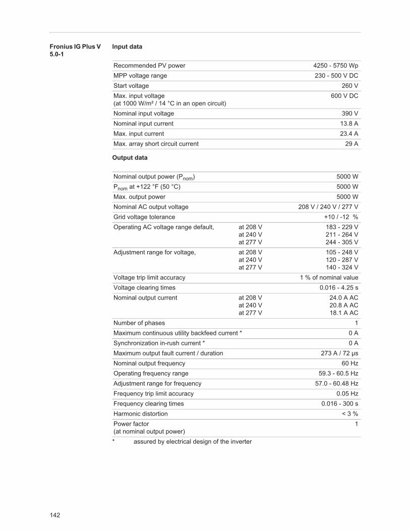
142
Fronius IG Plus V 5.0-1
Input data
Output data
* assured by electrical design of the inverter
Recommended PV power 4250 - 5750 WpMPP voltage range 230 - 500 V DCStart voltage 260 VMax. input voltage(at 1000 W/m² / 14 °C in an open circuit)
600 V DC
Nominal input voltage 390 VNominal input current 13.8 AMax. input current 23.4 AMax. array short circuit current 29 A
Nominal output power (Pnom) 5000 WPnom at +122 °F (50 °C) 5000 WMax. output power 5000 WNominal AC output voltage 208 V / 240 V / 277 VGrid voltage tolerance +10 / -12 %Operating AC voltage range default, at 208 V
at 240 Vat 277 V
183 - 229 V211 - 264 V244 - 305 V
Adjustment range for voltage, at 208 Vat 240 Vat 277 V
105 - 248 V120 - 287 V140 - 324 V
Voltage trip limit accuracy 1 % of nominal valueVoltage clearing times 0.016 - 4.25 sNominal output current at 208 V
at 240 Vat 277 V
24.0 A AC20.8 A AC18.1 A AC
Number of phases 1Maximum continuous utility backfeed current * 0 ASynchronization in-rush current * 0 AMaximum output fault current / duration 273 A / 72 μsNominal output frequency 60 HzOperating frequency range 59.3 - 60.5 HzAdjustment range for frequency 57.0 - 60.48 HzFrequency trip limit accuracy 0.05 HzFrequency clearing times 0.016 - 300 sHarmonic distortion < 3 %Power factor(at nominal output power)
1

143
EN-U
S
General data
Safety equipment
Maximum efficiency 96.2 %CEC efficiency at 208 V
at 240 Vat 277 V
95.5 %95.5 %96.0 %
Night consumption < 1 WConsumption during operation 15 WCooling Controlled forced ventilationDegree of protection NEMA 3RUnit dimensions w x h x d 17.09 x 36.46 x 9.61 in.
434 x 926 x 244 mmPower stage set weight 57 lbs.
26 kgConnection area weight 26 lbs.
12 kgShipping dimensions w x h x d 20.28 x 42.72 x 14.02 in.
515 x 1085 x 356 mmShipping weight 90 lbs.
41 kgPermissible ambient temperature (with 95% rel. humidity)
-13 °F - +131 °F- 25 °C - +55 °C
Permitted storage temperature (with 95% rel. humidity)
-13 °F - +149 °F- 25 °C - +65 °C
Ground fault protection internal GFDI(Ground Fault Detector/Interrupter)
Islanding protection integratedProtection against reverse polarity integratedOver temperature output power derating /
active cooling

144
Fronius IG Plus V 6.0-1
Input data
Output data
* assured by electrical design of the inverter
Recommended PV power 5100 - 6900 WpMPP voltage range 230 - 500 V DCStart voltage 260 VMax. input voltage(at 1000 W/m² / 14 °C in an open circuit)
600 V DC
Nominal input voltage 390 VNominal input current 16.6 AMax. input current 28.1 AMax. array short circuit current 35 A
Nominal output power (Pnom) 6000 WPnom at +122 °F (50 °C) 6000 WMax. output power 6000 WNominal AC output voltage 208 V / 240 V / 277 VGrid voltage tolerance +10 / -12 %Operating AC voltage range default, at 208 V
at 240 Vat 277 V
183 - 229 V211 - 264 V244 - 305 V
Adjustment range for voltage, at 208 Vat 240 Vat 277 V
105 - 248 V120 - 287 V140 - 324 V
Voltage trip limit accuracy 1 % of nominal valueVoltage clearing times 0.016 - 4.25 sNominal output current at 208 V
at 240 Vat 277 V
28.8 A AC25.0 A AC21.7 A AC
Number of phases 1Maximum continuous utility backfeed current * 0 ASynchronization in-rush current * 0 AMaximum output fault current / duration 273 A / 72 μsNominal output frequency 60 HzOperating frequency range 59.3 - 60.5 HzAdjustment range for frequency 57.0 - 60.48 HzFrequency trip limit accuracy 0.05 HzFrequency clearing times 0.016 - 300 sHarmonic distortion < 3 %Power factor(at nominal output power)
1

145
EN-U
S
General data
Safety equipment
Maximum efficiency 96.2 %CEC efficiency at 208 V
at 240 Vat 277 V
95.5 %96.0 %96.0 %
Night consumption < 1 WConsumption during operation 15 WCooling Controlled forced ventilationDegree of protection NEMA 3RUnit dimensions w x h x d 17.09 x 36.46 x 9.61 in.
434 x 926 x 244 mmPower stage set weight 57 lbs.
26 kgConnection area weight 26 lbs.
12 kgShipping dimensions w x h x d 20.28 x 42.72 x 14.02 in.
515 x 1085 x 356 mmShipping weight 90 lbs.
41 kgPermissible ambient temperature (with 95% rel. humidity)
-13 °F - +131 °F- 25 °C - +55 °C
Permitted storage temperature (with 95% rel. humidity)
-13 °F - +149 °F- 25 °C - +65 °C
Ground fault protection internal GFDI(Ground Fault Detector/Interrupter)
Islanding protection integratedProtection against reverse polarity integratedOver temperature output power derating /
active cooling

146
Fronius IG Plus V 7.5-1
Input data
Output data
* assured by electrical design of the inverter
Recommended PV power 6350 - 8600 WpMPP voltage range 230 - 500 V DCStart voltage 260 VMax. input voltage(at 1000 W/m² / 14 °C in an open circuit)
600 V DC
Nominal input voltage 390 VNominal input current 20.7 AMax. input current 35.1 AMax. array short circuit current 44 A
Nominal output power (Pnom) 7500 WPnom at +122 °F (50 °C) 7500 WMax. output power 7500 WNominal AC output voltage 208 V / 240 V / 277 VGrid voltage tolerance +10 / -12 %Operating AC voltage range default, at 208 V
at 240 Vat 277 V
183 - 229 V211 - 264 V244 - 305 V
Adjustment range for voltage, at 208 Vat 240 Vat 277 V
105 - 248 V120 - 287 V140 - 324 V
Voltage trip limit accuracy 1 % of nominal valueVoltage clearing times 0.016 - 4.25 sNominal output current at 208 V
at 240 Vat 277 V
36.1 A AC31.3 A AC27.1 A AC
Number of phases 1Maximum continuous utility backfeed current * 0 ASynchronization in-rush current * 0 AMaximum output fault current / duration 273 A / 72 μsNominal output frequency 60 HzOperating frequency range 59.3 - 60.5 HzAdjustment range for frequency 57.0 - 60.48 HzFrequency trip limit accuracy 0.05 HzFrequency clearing times 0.016 - 300 sHarmonic distortion < 3 %Power factor(at nominal output power)
1
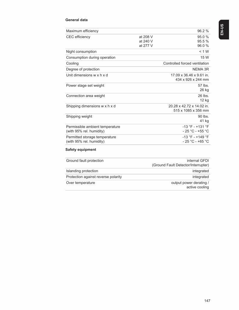
147
EN-U
S
General data
Safety equipment
Maximum efficiency 96.2 %CEC efficiency at 208 V
at 240 Vat 277 V
95.0 %95.5 %96.0 %
Night consumption < 1 WConsumption during operation 15 WCooling Controlled forced ventilationDegree of protection NEMA 3RUnit dimensions w x h x d 17.09 x 36.46 x 9.61 in.
434 x 926 x 244 mmPower stage set weight 57 lbs.
26 kgConnection area weight 26 lbs.
12 kgShipping dimensions w x h x d 20.28 x 42.72 x 14.02 in.
515 x 1085 x 356 mmShipping weight 90 lbs.
41 kgPermissible ambient temperature (with 95% rel. humidity)
-13 °F - +131 °F- 25 °C - +55 °C
Permitted storage temperature (with 95% rel. humidity)
-13 °F - +149 °F- 25 °C - +65 °C
Ground fault protection internal GFDI(Ground Fault Detector/Interrupter)
Islanding protection integratedProtection against reverse polarity integratedOver temperature output power derating /
active cooling

148
Fronius IG Plus V 10.0-1
Input data
Output data
* assured by electrical design of the inverter
Recommended PV power 8500 - 11500 WpMPP voltage range 230 - 500 V DCStart voltage 260 VMax. input voltage(at 1000 W/m² / 14 °C in an open circuit)
600 V DC
Nominal input voltage 390 VNominal input current 27.6 AMax. input current 46.7 AMax. array short circuit current 58 A
Nominal output power (Pnom) 9995 WPnom at +122 °F (50 °C) 9995 WMax. output power 9995 WNominal AC output voltage 208 V / 240 V / 277 VGrid voltage tolerance +10 / -12 %Operating AC voltage range default, at 208 V
at 240 Vat 277 V
183 - 229 V211 - 264 V244 - 305 V
Adjustment range for voltage, at 208 Vat 240 Vat 277 V
105 - 248 V120 - 287 V140 - 324 V
Voltage trip limit accuracy 1 % of nominal valueVoltage clearing times 0.016 - 4.25 sNominal output current at 208 V
at 240 Vat 277 V
48.1 A AC41.7 A AC36.1 A AC
Number of phases 1Maximum continuous utility backfeed current * 0 ASynchronization in-rush current * 0 AMaximum output fault current / duration 568 A / 104 μsNominal output frequency 60 HzOperating frequency range 59.3 - 60.5 HzAdjustment range for frequency 57.0 - 60.48 HzFrequency trip limit accuracy 0.05 HzFrequency clearing times 0.016 - 300 sHarmonic distortion < 3 %Power factor(at nominal output power)
1
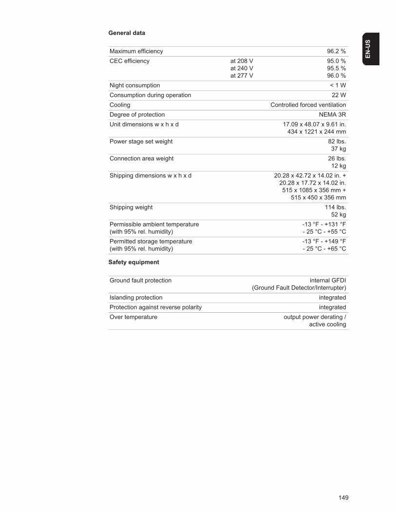
149
EN-U
S
General data
Safety equipment
Maximum efficiency 96.2 %CEC efficiency at 208 V
at 240 Vat 277 V
95.0 %95.5 %96.0 %
Night consumption < 1 WConsumption during operation 22 WCooling Controlled forced ventilationDegree of protection NEMA 3RUnit dimensions w x h x d 17.09 x 48.07 x 9.61 in.
434 x 1221 x 244 mmPower stage set weight 82 lbs.
37 kgConnection area weight 26 lbs.
12 kgShipping dimensions w x h x d 20.28 x 42.72 x 14.02 in. +
20.28 x 17.72 x 14.02 in.515 x 1085 x 356 mm +
515 x 450 x 356 mmShipping weight 114 lbs.
52 kgPermissible ambient temperature (with 95% rel. humidity)
-13 °F - +131 °F- 25 °C - +55 °C
Permitted storage temperature (with 95% rel. humidity)
-13 °F - +149 °F- 25 °C - +65 °C
Ground fault protection internal GFDI(Ground Fault Detector/Interrupter)
Islanding protection integratedProtection against reverse polarity integratedOver temperature output power derating /
active cooling
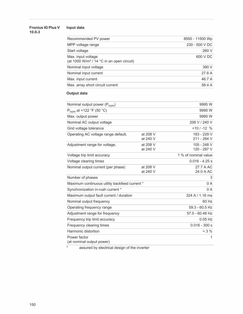
150
Fronius IG Plus V 10.0-3
Input data
Output data
* assured by electrical design of the inverter
Recommended PV power 8500 - 11500 WpMPP voltage range 230 - 500 V DCStart voltage 260 VMax. input voltage(at 1000 W/m² / 14 °C in an open circuit)
600 V DC
Nominal input voltage 390 VNominal input current 27.6 AMax. input current 46.7 AMax. array short circuit current 58.4 A
Nominal output power (Pnom) 9995 WPnom at +122 °F (50 °C) 9995 WMax. output power 9995 WNominal AC output voltage 208 V / 240 VGrid voltage tolerance +10 / -12 %Operating AC voltage range default, at 208 V
at 240 V183 - 229 V211 - 264 V
Adjustment range for voltage, at 208 Vat 240 V
105 - 248 V120 - 287 V
Voltage trip limit accuracy 1 % of nominal valueVoltage clearing times 0.016 - 4.25 sNominal output current (per phase) at 208 V
at 240 V27.7 A AC24.0 A AC
Number of phases 3Maximum continuous utility backfeed current * 0 ASynchronization in-rush current * 0 AMaximum output fault current / duration 324 A / 1.16 msNominal output frequency 60 HzOperating frequency range 59.3 - 60.5 HzAdjustment range for frequency 57.0 - 60.48 HzFrequency trip limit accuracy 0.05 HzFrequency clearing times 0.016 - 300 sHarmonic distortion < 3 %Power factor(at nominal output power)
1
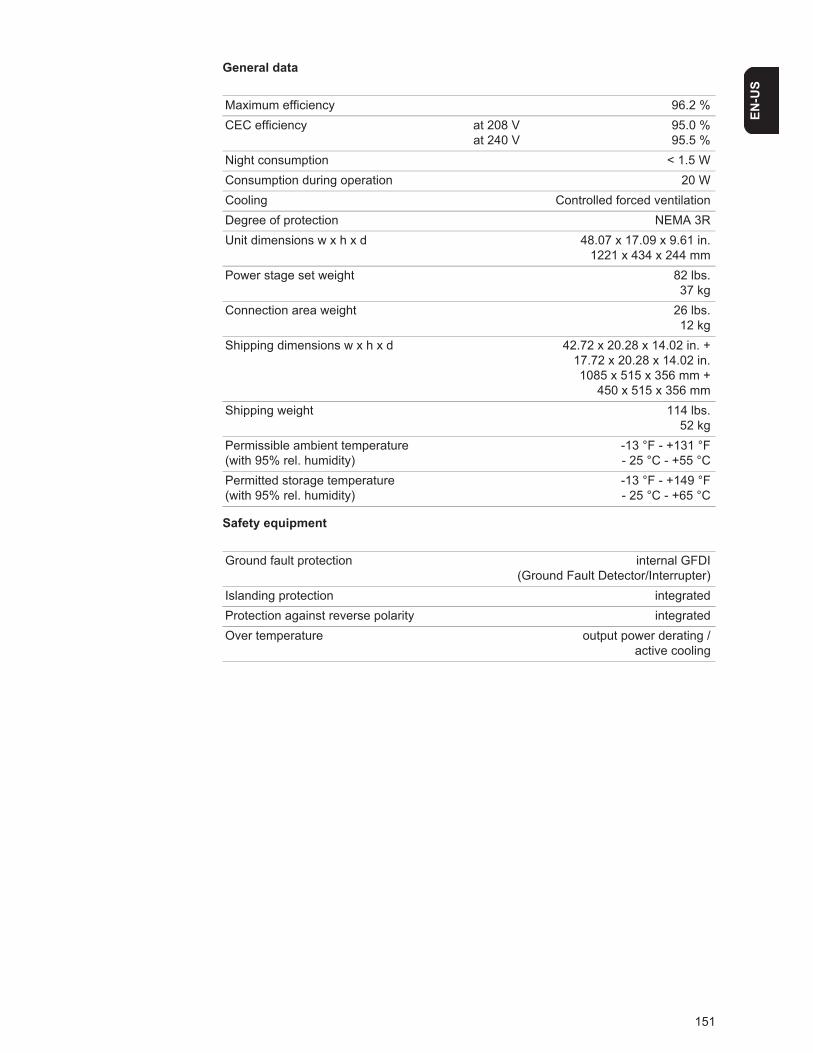
151
EN-U
S
General data
Safety equipment
Maximum efficiency 96.2 %CEC efficiency at 208 V
at 240 V95.0 %95.5 %
Night consumption < 1.5 WConsumption during operation 20 WCooling Controlled forced ventilationDegree of protection NEMA 3RUnit dimensions w x h x d 48.07 x 17.09 x 9.61 in.
1221 x 434 x 244 mmPower stage set weight 82 lbs.
37 kgConnection area weight 26 lbs.
12 kgShipping dimensions w x h x d 42.72 x 20.28 x 14.02 in. +
17.72 x 20.28 x 14.02 in.1085 x 515 x 356 mm +
450 x 515 x 356 mmShipping weight 114 lbs.
52 kgPermissible ambient temperature (with 95% rel. humidity)
-13 °F - +131 °F- 25 °C - +55 °C
Permitted storage temperature (with 95% rel. humidity)
-13 °F - +149 °F- 25 °C - +65 °C
Ground fault protection internal GFDI(Ground Fault Detector/Interrupter)
Islanding protection integratedProtection against reverse polarity integratedOver temperature output power derating /
active cooling
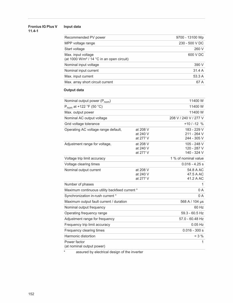
152
Fronius IG Plus V 11.4-1
Input data
Output data
* assured by electrical design of the inverter
Recommended PV power 9700 - 13100 WpMPP voltage range 230 - 500 V DCStart voltage 260 VMax. input voltage(at 1000 W/m² / 14 °C in an open circuit)
600 V DC
Nominal input voltage 390 VNominal input current 31.4 AMax. input current 53.3 AMax. array short circuit current 67 A
Nominal output power (Pnom) 11400 WPnom at +122 °F (50 °C) 11400 WMax. output power 11400 WNominal AC output voltage 208 V / 240 V / 277 VGrid voltage tolerance +10 / -12 %Operating AC voltage range default, at 208 V
at 240 Vat 277 V
183 - 229 V211 - 264 V244 - 305 V
Adjustment range for voltage, at 208 Vat 240 Vat 277 V
105 - 248 V120 - 287 V140 - 324 V
Voltage trip limit accuracy 1 % of nominal valueVoltage clearing times 0.016 - 4.25 sNominal output current at 208 V
at 240 Vat 277 V
54.8 A AC47.5 A AC41.2 A AC
Number of phases 1Maximum continuous utility backfeed current * 0 ASynchronization in-rush current * 0 AMaximum output fault current / duration 568 A / 104 μsNominal output frequency 60 HzOperating frequency range 59.3 - 60.5 HzAdjustment range for frequency 57.0 - 60.48 HzFrequency trip limit accuracy 0.05 HzFrequency clearing times 0.016 - 300 sHarmonic distortion < 3 %Power factor(at nominal output power)
1

153
EN-U
S
General data
Safety equipment
Maximum efficiency 96.2 %CEC efficiency at 208 V
at 240 Vat 277 V
95.5 %96.0 %96.0 %
Night consumption < 1 WConsumption during operation 22 WCooling Controlled forced ventilationDegree of protection NEMA 3RUnit dimensions w x h x d 17.09 x 48.07 x 9.61 in.
434 x 1221 x 244 mmPower stage set weight 82 lbs.
37 kgConnection area weight 26 lbs.
12 kgShipping dimensions w x h x d 20.28 x 42.72 x 14.02 in. +
20.28 x 17.72 x 14.02 in.515 x 1085 x 356 mm +
515 x 450 x 356 mmShipping weight 114 lbs.
52 kgPermissible ambient temperature (with 95% rel. humidity)
-13 °F - +131 °F- 25 °C - +55 °C
Permitted storage temperature (with 95% rel. humidity)
-13 °F - +149 °F- 25 °C - +65 °C
Ground fault protection internal GFDI(Ground Fault Detector/Interrupter)
Islanding protection integratedProtection against reverse polarity integratedOver temperature output power derating /
active cooling
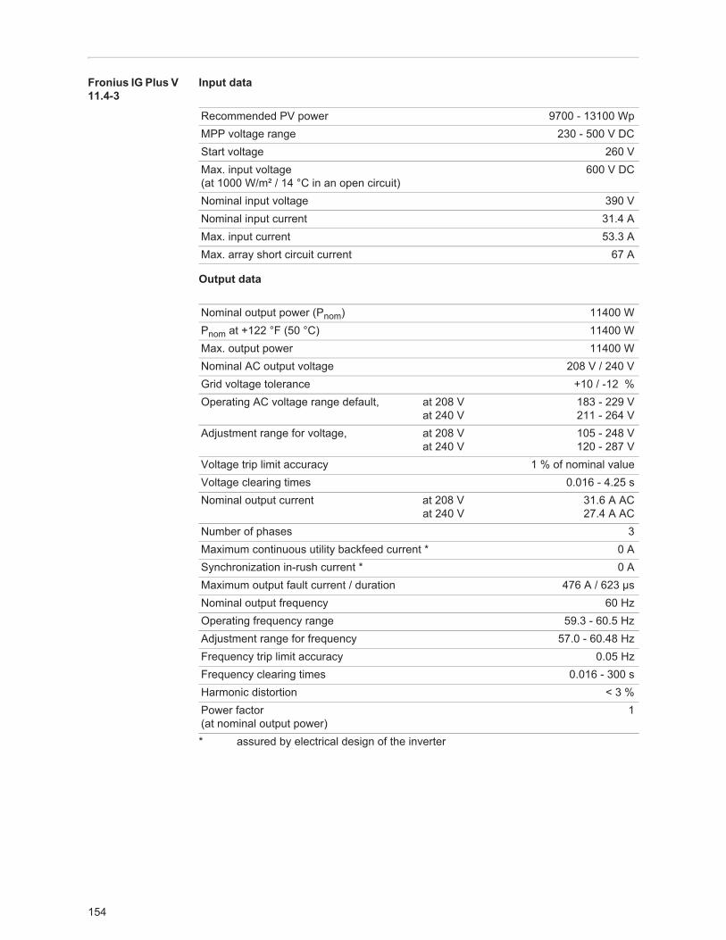
154
Fronius IG Plus V 11.4-3
Input data
Output data
* assured by electrical design of the inverter
Recommended PV power 9700 - 13100 WpMPP voltage range 230 - 500 V DCStart voltage 260 VMax. input voltage(at 1000 W/m² / 14 °C in an open circuit)
600 V DC
Nominal input voltage 390 VNominal input current 31.4 AMax. input current 53.3 AMax. array short circuit current 67 A
Nominal output power (Pnom) 11400 WPnom at +122 °F (50 °C) 11400 WMax. output power 11400 WNominal AC output voltage 208 V / 240 VGrid voltage tolerance +10 / -12 %Operating AC voltage range default, at 208 V
at 240 V183 - 229 V211 - 264 V
Adjustment range for voltage, at 208 Vat 240 V
105 - 248 V120 - 287 V
Voltage trip limit accuracy 1 % of nominal valueVoltage clearing times 0.016 - 4.25 sNominal output current at 208 V
at 240 V31.6 A AC27.4 A AC
Number of phases 3Maximum continuous utility backfeed current * 0 ASynchronization in-rush current * 0 AMaximum output fault current / duration 476 A / 623 μsNominal output frequency 60 HzOperating frequency range 59.3 - 60.5 HzAdjustment range for frequency 57.0 - 60.48 HzFrequency trip limit accuracy 0.05 HzFrequency clearing times 0.016 - 300 sHarmonic distortion < 3 %Power factor(at nominal output power)
1

155
EN-U
S
General data
Safety equipment
Maximum efficiency 96.2 %CEC efficiency at 208 V
at 240 V95.0 %95.5 %
Night consumption < 1 WConsumption during operation 22 WCooling Controlled forced ventilationDegree of protection NEMA 3RUnit dimensions w x h x d 17.09 x 48.07 x 9.61 in.
434 x 1221 x 244 mmPower stage set weight 82 lbs.
37 kgConnection area weight 26 lbs.
12 kgShipping dimensions w x h x d 20.28 x 42.72 x 14.02 in. +
20.28 x 17.72 x 14.02 in.515 x 1085 x 356 mm +
515 x 450 x 356 mmShipping weight 114 lbs.
52 kgPermissible ambient temperature (with 95% rel. humidity)
-13 °F - +131 °F- 25 °C - +55 °C
Permitted storage temperature (with 95% rel. humidity)
-13 °F - +149 °F- 25 °C - +65 °C
Ground fault protection internal GFDI(Ground Fault Detector/Interrupter)
Islanding protection integratedProtection against reverse polarity integratedOver temperature output power derating /
active cooling
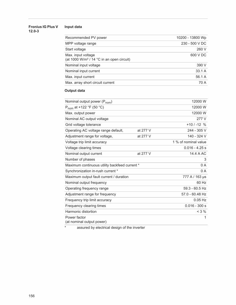
156
Fronius IG Plus V 12.0-3
Input data
Output data
* assured by electrical design of the inverter
Recommended PV power 10200 - 13800 WpMPP voltage range 230 - 500 V DCStart voltage 260 VMax. input voltage(at 1000 W/m² / 14 °C in an open circuit)
600 V DC
Nominal input voltage 390 VNominal input current 33.1 AMax. input current 56.1 AMax. array short circuit current 70 A
Nominal output power (Pnom) 12000 WPnom at +122 °F (50 °C) 12000 WMax. output power 12000 WNominal AC output voltage 277 VGrid voltage tolerance +10 / -12 %Operating AC voltage range default, at 277 V 244 - 305 VAdjustment range for voltage, at 277 V 140 - 324 VVoltage trip limit accuracy 1 % of nominal valueVoltage clearing times 0.016 - 4.25 sNominal output current at 277 V 14.4 A ACNumber of phases 3Maximum continuous utility backfeed current * 0 ASynchronization in-rush current * 0 AMaximum output fault current / duration 777 A / 163 μsNominal output frequency 60 HzOperating frequency range 59.3 - 60.5 HzAdjustment range for frequency 57.0 - 60.48 HzFrequency trip limit accuracy 0.05 HzFrequency clearing times 0.016 - 300 sHarmonic distortion < 3 %Power factor(at nominal output power)
1
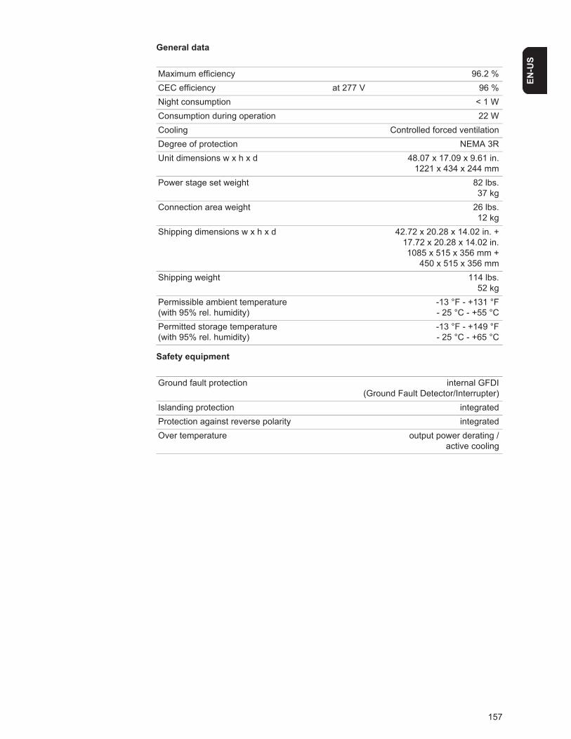
157
EN-U
S
General data
Safety equipment
Maximum efficiency 96.2 %CEC efficiency at 277 V 96 %Night consumption < 1 WConsumption during operation 22 WCooling Controlled forced ventilationDegree of protection NEMA 3RUnit dimensions w x h x d 48.07 x 17.09 x 9.61 in.
1221 x 434 x 244 mmPower stage set weight 82 lbs.
37 kgConnection area weight 26 lbs.
12 kgShipping dimensions w x h x d 42.72 x 20.28 x 14.02 in. +
17.72 x 20.28 x 14.02 in.1085 x 515 x 356 mm +
450 x 515 x 356 mmShipping weight 114 lbs.
52 kgPermissible ambient temperature (with 95% rel. humidity)
-13 °F - +131 °F- 25 °C - +55 °C
Permitted storage temperature (with 95% rel. humidity)
-13 °F - +149 °F- 25 °C - +65 °C
Ground fault protection internal GFDI(Ground Fault Detector/Interrupter)
Islanding protection integratedProtection against reverse polarity integratedOver temperature output power derating /
active cooling
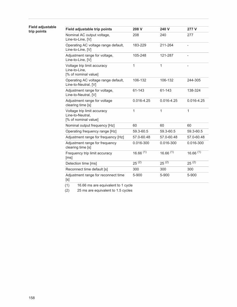
158
Field adjustable trip points
(1) 16.66 ms are equivalent to 1 cycle(2) 25 ms are equivalent to 1.5 cycles
Field adjustable trip points 208 V 240 V 277 VNominal AC output voltage,Line-to-Line, [V]
208 240 277
Operating AC voltage range default,Line-to-Line, [V]
183-229 211-264 -
Adjustment range for voltage,Line-to-Line, [V]
105-248 121-287 -
Voltage trip limit accuracyLine-to-Line,[% of nominal value]
1 1 -
Operating AC voltage range default,Line-to-Neutral, [V]
106-132 106-132 244-305
Adjustment range for voltage,Line-to-Neutral, [V]
61-143 61-143 138-324
Adjustment range for voltageclearing time [s]
0.016-4.25 0.016-4.25 0.016-4.25
Voltage trip limit accuracyLine-to-Neutral,[% of nominal value]
1 1 1
Nominal output frequency [Hz] 60 60 60Operating frequency range [Hz] 59.3-60.5 59.3-60.5 59.3-60.5Adjustment range for frequency [Hz] 57.0-60.48 57.0-60.48 57.0-60.48Adjustment range for frequencyclearing time [s]
0.016-300 0.016-300 0.016-300
Frequency trip limit accuracy[ms]
16.66 (1) 16.66 (1) 16.66 (1)
Detection time [ms] 25 (2) 25 (2) 25 (2)
Reconnect time default [s] 300 300 300Adjustment range for reconnect time [s]
5-900 5-900 5-900
159
EN-U
S
Relevant Standards and Directives
Relevant stan-dards and direc-tives
Grid Failure The standard measurement and safety procedures integrated into the inverter ensure that the power feed is immediately interrupted in the event of a grid failure (shut-off by the utility or damage to lines).
- UL 1741- IEEE 1547- IEEE 1547.1- ANSI/IEEE C62.41
- FCC Part 15 A & B- NEC Article 690- C22. 2 No. 107.1-01
(September 2001)
160
Warranty and Disposal
FRONIUS USA limited 10-year warranty
At Fronius, we have been designing and manufacturing high quality power electronics equipment for over 60 years. And all our production facilities are ISO 9001 certified.
You will probably not encounter any service-related issues with your Fronius IG Plus Solar Inverter.However, in the unlikely event that within Ten (10) years from the original purchase you discover a problem caused by defects in either workmanship or materials, we will see that the device is either repaired or replaced.Repair or replacement depends on Fronius’s evaluation of the issue and what we decide makes the most sense according to the situation.The warranty is based on the inverter’s serial number, allowing the warranty to be trans-ferred to another owner if the Fronius IG Plus solar inverter remains installed in the original installation location. Because the warranty is tied to the serial number, there is no paper-work to transfer the warranty to a new owner.
The Fronius IG Plus Solar Inverters are designed to withstand normal operating conditions and typical wear and tear when the Fronius IG Plus Solar Inverter is used for its original intent, in compliance with the Fronius IG Plus Installation and Operational Manual(s) sup-plied with the original equipment.This warranty does not cover damages by improper installation or operation, misuse, abuse, manipulation, alterations or repair attempts, accidents, fire, floods, acts of God, and incidental or consequential damage caused by defects with other components of the solar system. This warranty does not extend beyond the original cost of the Fronius IG Plus So-lar Inverter.
Policy and proce-dure for warranty returns and re-pairs
To obtain service you must follow this policy and procedure for warranty returns and re-pairs:- All returned Fronius IG Plus Solar Inverters require a Returned Merchandise Authori-
zation Number (RMA).- A request for an RMA number requires the following information:
- Proof of purchase in the form of the original invoice- Model number of the Fronius IG Plus solar inverter- Serial number of the Fronius IG Plus inverter- Description of the problem- Shipping address for the repaired or replaced equipment
- All Fronius IG Plus solar inverters authorized for return by FRONIUS USA must be re-turned in their original shipping container or packaging providing equal protection.
- Shipping costs to FRONIUS USA and back to the purchaser of repaired or replace-ment Fronius IG Plus Solar Inverters is the responsibility of FRONIUS USA
- The warranty period of any repaired or replacement inverter is 12 months after ship-ment from FRONIUS USA or the original warranty period which ever is later
- Labor costs related to uninstalling the defective equipment and re-installing the re-paired or replacement equipment are not covered under the warranty.
Some states do not allow the exclusion or limitation of incidental or consequential damag-es. This warranty gives you specific legal rights, and you may also have other rights, which vary from state to state.
FRONIUS USA LLC General Terms and Conditions apply.
Contact your local dealer or FRONIUS Service Partner for immediate handling of warranty issues. For service assistance to resolve a Fronius IG Plus solar inverter problem, or for product information please contact:

161
EN-U
S
Fronius USA LLC - Solar Electronics Division6797 Fronius Drive, Portage, IN 46368E-Mail: [email protected]://www.fronius-usa.com
Disposal Should your inverter be replaced at some future date, Fronius will accept the obsolete equipment back and provide for its proper recycling.
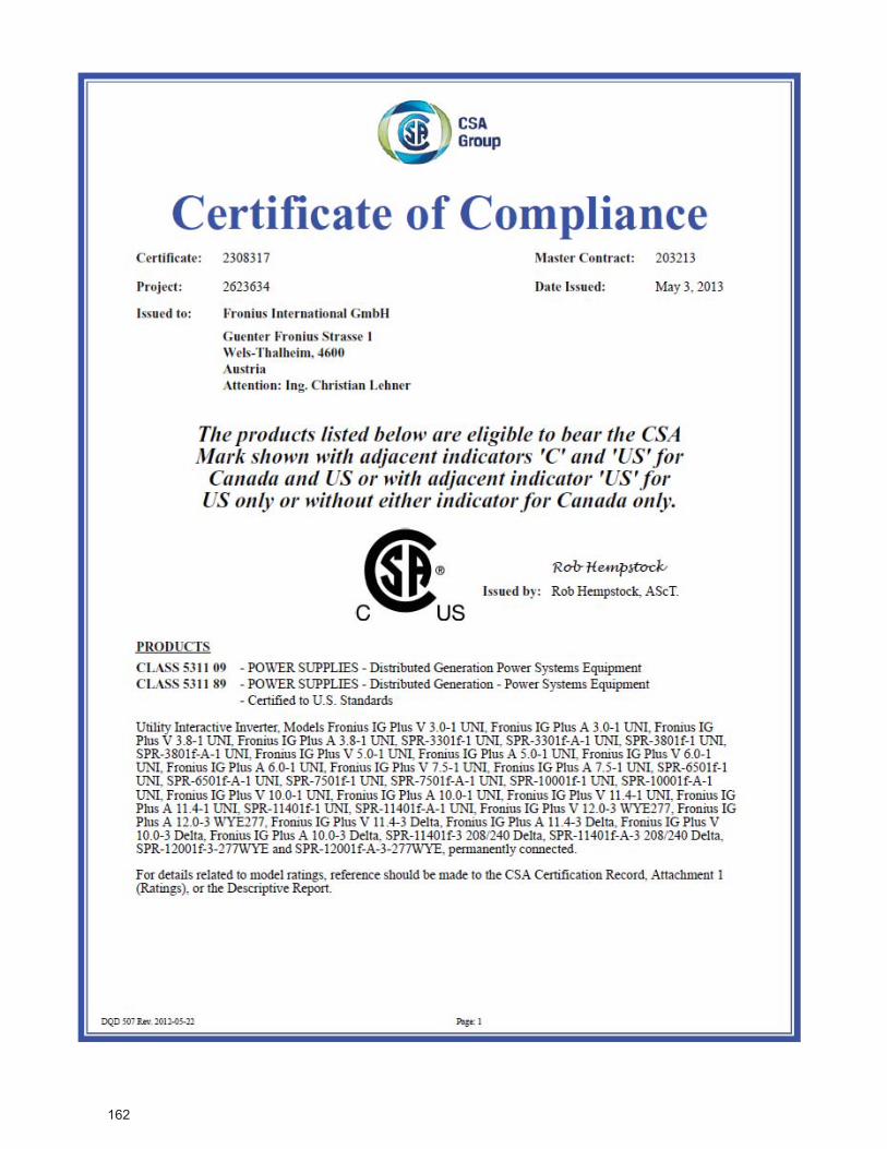
162
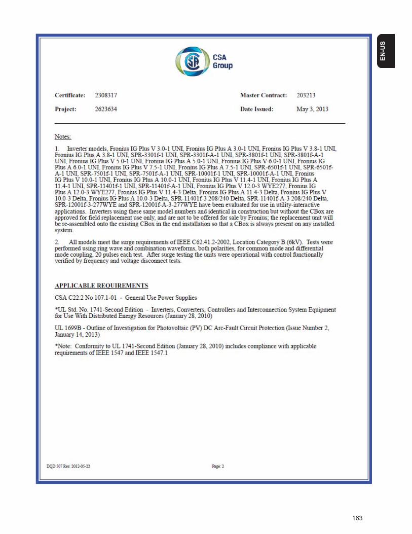
163
EN-U
S
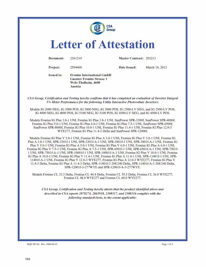
164
165
EN-U
S

166

167
EN-U
S

168

169
EN-U
S
Fronius Worldwide - www.fronius.com/addresses
Under http://www.fronius.com/addresses you will find all addresses of our sales branches and partner firms!
Fronius International GmbH4600 Wels, Froniusplatz 1, AustriaE-Mail: [email protected]://www.fronius.com
Fronius USA LLC Solar Electronics Division6797 Fronius Drive, Portage, IN 46368E-Mail: [email protected]://www.fronius-usa.com