Embed Size (px)
Citation preview

Rhein-Nadel Automation GmbH 1 14.04.2014
VT-BA ESR2000-GB
Operating Instructions
for the Control Units
for Vibratory Drives
Type ESR 2000
BA
Rhein-Nadel Automation GmbH
Rhein-Nadel Automation GmbH 2 14.04.2014
VT-BA ESR2000-GB
Table of contents Chapt................................................................................................ ........................ Page
1 Technical datas................................................................................................... 3
2 Safety notes........................................................................................ ........... 4
3 Commissioning instructions ............................................................................... 4
4 Operation 9
5 Dimensional drawing..................................................................................... 16
6 Connection diagram....................................................................................... 17
Declaration of conformity
as defined by
Low voltage directive 2014/35/EU
and EMC directive 2014/30/EU
Herewith we declare that the product complies with the following provisions:
Low voltage directive 2014/35/EU
EMC directive 2014/30/EU
applied harmonized standards:
DIN EN 60204 T1
EN 61439-1
remarks:
Rhein-Nadel-Automation
--------------------------------
Managing Director
Jack Grevenstein

Rhein-Nadel Automation GmbH 3 14.04.2014
VT-BA ESR2000-GB
1.1 Performance Characteristics This compact control unit has been designed to operate a bowl or linear feeder. The unit has the following performance characteristics: - a power regulator for vibratory drive unit with variable output frequency, load current max. 6A - two sensor amplifiers with independently adjustable time levels (on/off). - 24V DC remote control input. - two relay outputs and two optocouplers for status messages and further links. - a membrane keyboard for setting and editing the operating values (parameters) in the setting menus. - plug connections for
- bowl or linear feeder - sensors - communication
- double-pole mains power switch -
1.2 EC Conformity
The control device corresponds to the following regulations:
Low voltage directive 2014/35/EU
EMC directive 2014/30/EU
Applied harmonized standards:
DIN EN 60204 T1
EN 61439-1
1.3 Technical Data
Mains voltage: 230 Volt AC, 50/60 Hz, +20 / -15% 110 Volt AC, 50/60 Hz, +10 / -10%
Output voltage: 0 ... 208 Veff / 230 VAC ; 0 ... 98Veff / 110VAC
Load current channel 1: 6 Aeff
Minimum load current: 80 mA Output frequency 30 to 140 Hertz
Internal fuse: F1 = 10A Soft start time, soft stop time 0 ... 5 sec., can be selected separately
External setpoint: 0 ... 10V DC Sensor inputs: 2
Remote control input: 24V DC (10-24 VDC) Sensor power supply: 24V DC, max. 60 mA (per sensor input)
Sensor delay ON: 0 ... 60 sec. Sensor delay OFF: 0 ... 60 sec.
Outputs: 2 relays / 2 potential-free change-over contacts Status output (optocoupler): max. 30V DC 10mA, 2 voltage-fed open contact
Relay contacts: max. 6A 250V AC Operating temperature: 0 ... 50° C
Type of protection: IP 54
1.4 Accessoires
Label Denomination Type Manufacteur Supplier RNA-Mat-code XS1 Connector Harting XS3 Coupler connector, 5-poles, straight 09 0113 70 05 Binder EVG 35051144 XS3 Coupler connector, 5-poles, angular 99 0113 75 05 Binder EVG 35002546 XS4 Coupler connector, 7-poles, straight 09 0126 70 07 Binder EVG 35051153 XS4 Coupler connector, 7-poles, angular 99 0126 75 07 Binder EVG 35002545
Rhein-Nadel Automation GmbH 4 14.04.2014
VT-BA ESR2000-GB
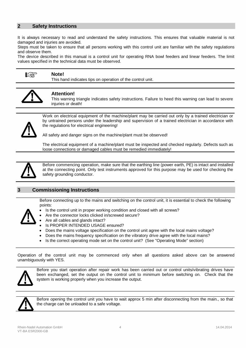
2 Safety Instructions
It is always necessary to read and understand the safety instructions. This ensures that valuable material is not damaged and injuries are avoided. Steps must be taken to ensure that all persons working with this control unit are familiar with the safety regulations and observe them. The device described in this manual is a control unit for operating RNA bowl feeders and linear feeders. The limit values specified in the technical data must be observed.
Note! This hand indicates tips on operation of the control unit.
Attention! This warning triangle indicates safety instructions. Failure to heed this warning can lead to severe injuries or death!
Work on electrical equipment of the machine/plant may be carried out only by a trained electrician or by untrained persons under the leadership and supervision of a trained electrician in accordance with the regulations for electrical engineering! All safety and danger signs on the machine/plant must be observed! The electrical equipment of a machine/plant must be inspected and checked regularly. Defects such as loose connections or damaged cables must be remedied immediately!
Before commencing operation, make sure that the earthing line (power earth, PE) is intact and installed at the connecting point. Only test instruments approved for this purpose may be used for checking the safety grounding conductor.
3 Commissioning Instructions
Before connecting up to the mains and switching on the control unit, it is essential to check the following points:
Is the control unit in proper working condition and closed with all screws?
Are the connector locks clicked in/screwed secure?
Are all cables and glands intact?
Is PROPER INTENDED USAGE ensured?
Does the mains voltage specification on the control unit agree with the local mains voltage?
Does the mains frequency specification on the vibratory drive agree with the local mains?
Is the correct operating mode set on the control unit? (See "Operating Mode" section)
Operation of the control unit may be commenced only when all questions asked above can be answered unambiguously with YES.
Before you start operation after repair work has been carried out or control units/vibrating drives have been exchanged, set the output on the control unit to minimum before switching on. Check that the system is working properly when you increase the output.
Before opening the control unit you have to wait approx 5 min after disconnecting from the main., so that the charge can be unloaded to a safe voltage.

Rhein-Nadel Automation GmbH 5 14.04.2014
VT-BA ESR2000-GB
3.1 OPERATING MODE To avoid mechanical and/or electrical damage occurring to the ESR 2000 control or connected equipment, the parameters listed in the tables below must be strictly adhered to. If you cannot find your particular type of drive unit listed in the tables then contact RNA AUTOMATION for advice.
To make shure that the drive unit will run smooth and stabel, it is necessary to use use a good balanced bowl. Please refer also to the manuals of the drive units, to see how the springs have to be adjusted.
Table 1
Bowl Feeder max. current max. magnet Frequency Colour of Type of Drive Aeff gap mm range Magnet
SRC - N 160 - 2 0,6 0,5 90...120 Hz Black SRC - N 200 - 2 1,2 0,5 90...120 Hz black SRC - B 200 - 2 1,2 0,5 90...120 Hz black SRC - N 250 - 2 2,6 1,2 90...120 Hz black SRC - B 250 - 2 2,8 1,2 90...120 Hz black SRC - N 400 - 1 3,8 2,8 45...60 Hz red SRC - N 400 - 2 4,3 1,2 90...120 Hz black SRHL 400 - 1 5,7 2,8 45...60 Hz red SRHL 400 - 2 5,3 1,5 90...120 Hz black SRC - N 630 - 1 5 2,8 45...60 Hz red
Table 2
Linear Feeder max. current max. magnet Frequency Colour of Type of Drive Aeff gap mm range Magnet
SLL 175 0,07 0,8 90…120 Hz black SLL 400 0,6 1 90...120 Hz black SLL 800 1,4 3 45...60 Hz red SLL 804 <1600 1,4 3 45...60 Hz red
SLL 804 1600 2,8 3 45...60 Hz red
SLF 1000 2,6 2,5 45...60 Hz red SLF 1500 45…60 Hz red GL 01 0,6 1,0 90...120 Hz black GL 1 1,1 1,2 90...120 Hz black SLK - N 6 1,4 2,5 45...60 Hz red SLK - N 6 G 1,4 2,5 45...60 Hz red
For easy differentiation (recognition of frequency ranges) RNA magnet cables are colour coded as follows:
Cable Colour Netfrequency Variable Frequency
Black 50/(60) Hz 45...60 Hz Grey 100/(120) Hz 90...120 Hz
WARNING: To avoid serious mechanical damage to the feeder unit, the maximum magnet gap and maximum current level MUST NOT be exceeded.
3.1.1 First Running
RNA can supply an adapter for running with easy plug-in between controller and drive unit. The adapter included a measuring unit for load current and coil voltage with a disconnecting switch. Type ESZ 01

Rhein-Nadel Automation GmbH 6 14.04.2014
VT-BA ESR2000-GB
Please note that all parameters of the controller are tuned up to the bowl feeder if supplied as a package
with an ESR 2000 unit and in parameter 143 User 0.3 stored. All settings are stored and retrievable.
Reconfigurations, exchange of controllers or mechanical alterations may cause damages to springs, vibrating plate, tooling or transfer devices, when putting the feeder improperly into operation
3.1.2 Initial Set Up
Procedure:
1. Check the feeder type against the ones shown in Table 1 and 2 for correct magnet gap settings, correct current settings and the frequency range.
2. Connect the ESR2000 control without feeder to the mains supply and switch on.
3. Do not connect the feeder unit to the ESR2000 at this stage.
4. Select Code 001:
Select code KANAL l
KANAL 2
CODE Set code
Code C001 KANAL l
KANAL 2
CODE
4. Set Amplitude to 50 % :
Set Amplitude KANAL l
KANAL 2
CODE
0 - 100 %
5. Set the frequency. Refer to table 1 or 2 for the drive unit
Frequency KANAL l
KANAL 2
CODE
45 - 120
6. Save settings:
Return KANAL l
KANAL 2
CODE
Store and return to
main menu
7. Switch off the controller
8. Connect the feeder to the controller
9. Switch on the controller
The drive unit must run now!
10. Select again Code 001
Select code KANAL l
KANAL 2
CODE Set code
Code C001 KANAL l
KANAL 2
CODE
11. Set Amplitude to 90 % :
Set Amplitude
KANAL l
KANAL 2
CODE
0 - 100 %
12. Reduce the frequency until the correct speed and vibration is achieved.
Operating Frequency KANAL l
KANAL 2
CODE
45 - 120
13. Check the current load is below the maximum level indicated in Table 1 and 2! For easy running and to determine the load current, RNA can supply a plug adapter ESZ 01
14. Save your settings
Return KANAL l
KANAL 2
CODE
Store and return to
main menu
With Code C210 you can reset to factory settings or restoring the stored user parameters
Rhein-Nadel Automation GmbH 7 14.04.2014
VT-BA ESR2000-GB
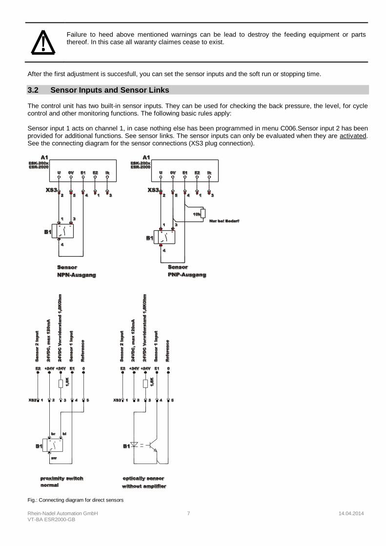
Failure to heed above mentioned warnings can be lead to destroy the feeding equipment or parts thereof. In this case all waranty claimes cease to exist.
After the first adjustment is succesfull, you can set the sensor inputs and the soft run or stopping time.
3.2 Sensor Inputs and Sensor Links
The control unit has two built-in sensor inputs. They can be used for checking the back pressure, the level, for cycle control and other monitoring functions. The following basic rules apply: Sensor input 1 acts on channel 1, in case nothing else has been programmed in menu C006.Sensor input 2 has been provided for additional functions. See sensor links. The sensor inputs can only be evaluated when they are activated. See the connecting diagram for the sensor connections (XS3 plug connection).
Fig.: Connecting diagram for direct sensors

Rhein-Nadel Automation GmbH 8 14.04.2014
VT-BA ESR2000-GB
+ -
A
XS 3.2 /
XS 3 /
XS 3.1 /
Termination of a sensor and a contact by adapter.
Housing
Y - Cable as a distribution
Fig.: Connecting diagram for sensors on 2-way
distributor
XS 3.2 /
XS 3 /
XS 3.1 /
Amplifierless photocell with externall preresistor 1.8 kOhms, 0.25W resistor soldered into plug.
Housing
Y - Cable as distrubution
Fig.: Connecting diagram for photocell without
amplifier on the 2-way distributor
3.3 Status Outputs and Relays The status outputs are used for remote diagnostics of the control unit operating mode or for linking several control units together. They are unassigned NPN-doped transistor routes and are potential-free. The transistor route is always connected at the STANDBY status output when the control unit is connected to the mains and switched on with the mains power switch. The ON ACTION status output requires the same conditions as STANDBY. Channel 1 must also be active as the transistor will block if it is set to BACK PRESSURE, OFF or STOP. The status outlet and the remote control should be wired via the XS4 plug connection. The two relays have different functions. K1 works as a status relay parallel to the ON ACTION back pressure output. K2 is either used for the delayed switch-off of blow-off air or for a cycle control function for one of the two sensor channels. The connections and the cable inlets are on the right-hand side of the control unit. The terminal strip is behind the control unit panel.
Rhein-Nadel Automation GmbH 9 14.04.2014
VT-BA ESR2000-GB
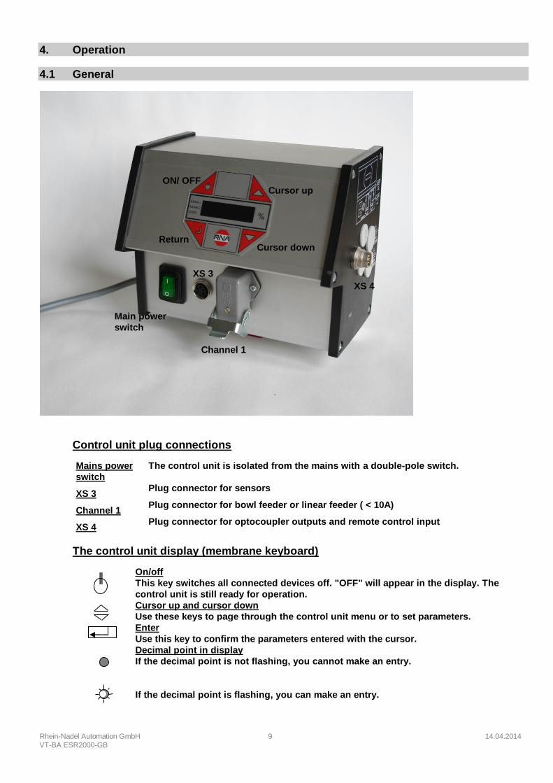
4. Operation
4.1 General
Control unit plug connections
Mains power
switch
The control unit is isolated from the mains with a double-pole switch.
XS 3 Plug connector for sensors
Channel 1 Plug connector for bowl feeder or linear feeder ( < 10A)
XS 4 Plug connector for optocoupler outputs and remote control input
The control unit display (membrane keyboard)
On/off
This key switches all connected devices off. "OFF" will appear in the display. The
control unit is still ready for operation. Cursor up and cursor down
Use these keys to page through the control unit menu or to set parameters. Enter
Use this key to confirm the parameters entered with the cursor. Decimal point in display
If the decimal point is not flashing, you cannot make an entry.
If the decimal point is flashing, you can make an entry.
Cursor down Return
ON/ OFF Cursor up
Main power
switch
Channel 1
XS 3
XS 4

Rhein-Nadel Automation GmbH 10 14.04.2014
VT-BA ESR2000-GB
4.2 Switching on the Control Unit Switch on the control unit with the mains power switch. The main menu will appear in the display showing the last setpoint set in channel 1 (Bowl feeder or linear feeder feed rate).
KANAL l
KANAL 2
CODE The following displays may also appear depending on the circuit state of the unit.
KANAL l
KANAL 2
CODE
The remote control has been activated but is currently not available on the unit.
KANAL l
KANAL 2
CODE
The unit has been switched off with the upper left-hand key on the membrane keyboard, all functions are blocked.
KANAL l
KANAL 2
CODE
The back pressure monitoring sensor has been assigned thus switching off channel 1 (Bowl feeder).
4.3 Main Menu/Setting and Displaying Setpoints for Channel 1 Display of setpoint or the channel 1
output (Bowl feeder)
Alternatively: STOP, OFF or BACK
PRESSURE
(see above)
KANAL l
KANAL 2
CODE
No entries possible
Enter code to change or make
required settings. KANAL l
KANAL 2
CODE
Enter code. See section 4.4 for description of code.
Setpoint preset
(Bowl feeder or linear feeder) KANAL l
KANAL 2
CODE
Entry in %; return to
display mode to store
From these three basic displays you can page through the main menu using the cursor keys (UP/DOWN). Press the ENTER key in the main menu to activate a menu item for setting or adjustment. The decimal point will flash once you have pressed the ENTER key. Changes can now be made using the cursor keys (UP/DOWN). Confirm the entries by pressing the ENTER key again. The decimal point will no longer flash. You can scroll further through the menu using the cursor keys. This procedure is also used in the code menus described below. All displays shown in the following section represent the factory settings. If the actual display on the control unit differs, the factory setting has been changed in the individual codes for a specific application.
4.4 Description of the Individual Codes for Programming the Control Unit
KANAL l
KANAL 2
CODE
Settings for channel 1 The following functions can be set or limited for channel 1 in this submenu: - vibration amplitude - signal direction of the remote control - remote control - soft start time and soft stop time
KANAL l
KANAL 2
CODE
Lock setpoint This submenu allows the setpoints (oscillation amplitude) to be blocked in the main menu. The setpoints for channel 1 can no longer be changed in the main menu. This prevents the output values being accidentally changed. Changes can only be made using code C001.
KANAL l
KANAL 2
CODE
Setting sensor input 1 Sensor input 1 is activated in this submenu. The following functions can also be set. - invert input signal direction - time before switch-on
Rhein-Nadel Automation GmbH 11 14.04.2014
VT-BA ESR2000-GB
- time before switch-off
KANAL l
KANAL 2
CODE
Setting sensor input 2 Sensor input 2 is activated in this submenu. The following functions can also be set. - invert input signal direction - time before switch-on - time before switch-off
KANAL l
KANAL 2
CODE
Selecting the sensor links The sensors activated with codes C004 and C005 can be linked to each other in this submenu.
KANAL l
KANAL 2
CODE
Setting the cycle control system Set the sensor input to be monitored and how the control will react when there is a fault.
KANAL l
KANAL 2
CODE
Display status This submenu is used to check the set vibration frequency and the sensor inputs and reset of error signals
KANAL l
KANAL 2
CODE
Programmed application examples Call memorized settings P1-10 based on application examples.
(ask for our catalogue fax 0241/5109-219 or by Internet www.rna.de)
KANAL l
KANAL 2
CODE
Output preset with an external voltage. 0-10V or potentiometer
KANAL l
KANAL 2
CODE
Store parameters If the values (user parameters) previously set in the different submenus are to be stored, call this submenu.
KANAL l
KANAL 2
CODE
Block all setting functions This code blocks all entry options on the control unit. The values can no longer be changed. The menu can now only be enabled using this code.
KANAL l
KANAL 2
CODE
Reset parameters This submenu allows the user to reset the control unit to the factory settings. If user parameters have been stored, the control unit can also be set to these settings.
4.5 Application-specific Changes to the Factory Settings
4.5.1 Code C001 for power output
Aim: Setting and limiting the vibration amplitude, the remote control, the soft start time and the soft stop time. Select code
KANAL l
KANAL 2
CODE
Set code
Code C001 KANAL l
KANAL 2
CODE
Set vibration amplitude KANAL l
KANAL 2
CODE
0 - 100 %
Limit vibration amplitude For RNA-Feeder with 100V/200 V Magnets 90%
KANAL l
KANAL 2
CODE
50 - 100 % (*)
Remote control KANAL l
KANAL 2
CODE
I = active
0 = inactive
Remote control signal direction KANAL l
KANAL 2
CODE
I = start = 24V DC
0 = stop = 24V DC
Soft start time KANAL l
KANAL 2
CODE
0 - 5 sec.
Soft stop time KANAL l
KANAL 2
CODE
0 - 5 sec.

Rhein-Nadel Automation GmbH 12 14.04.2014
VT-BA ESR2000-GB
Operating Frequency
(see 3.1 Operating Mode)
KANAL l
KANAL 2
CODE
35 - 140
Return KANAL l
KANAL 2
CODE
Store and return to
main menu
4.5.2 Code C003 Lock Setpoint
Aim: Blocking the setpoints in the main menu. The values can no longer be changed directly. Changes can only be made using code C001. Select code
KANAL l
KANAL 2
CODE
Set code
Code C003 KANAL l
KANAL 2
CODE
Setpoint (vibration amplitude) KANAL l
KANAL 2
CODE
1 = can be set
0 = entry blocked
Return KANAL l
KANAL 2
CODE
Store and return to
main menu
4.5.3 Code C004 Sensor Input 1 and Code C005 Sensor Input 2
Aim: Activating and setting the sensor inputs Select code
KANAL l
KANAL 2
CODE
Set code
Code C004 KANAL l
KANAL 2
CODE
Sensor 1 input KANAL l
KANAL 2
CODE
I = active
0 = inactive
Invert input signal direction KANAL l
KANAL 2
CODE
I = start = 24V DC
0 = stop = 24V DC
Sensor state delay
FREE, time before switch on. KANAL l
KANAL 2
CODE
0 -60 sec.
Sensor state delay
ASSIGNED, time before switch-off.
KANAL l
KANAL 2
CODE
0 -60 sec.
Return KANAL l
KANAL 2
CODE
Store and return to
main menu
Code C005 is used for sensor input 2 in the same way.
4.5.4 Code C006 Sensor Links
Aim: Linking two previously activated sensor inputs.
Select code KANAL l
KANAL 2
CODE set code
Code C006 KANAL l
KANAL 2
CODE
Only one of the eight sensor links can be set active.
And (And) link with blow-off of the
outlet tracks KANAL l
KANAL 2
CODE
I = active
0 = inactive
And (und) link without blow-off of the
outlet tracks (since Versions-No. 10)
KANAL l
KANAL 2
CODE
I = active
0 = inactive
Or link KANAL l
KANAL 2
CODE
I = active
0 = inactive
Min/Max link KANAL l
KANAL 2
CODE
I = active
0 = inactive
And / S2 link (since Versions-No. 10) KANAL l
KANAL 2
CODE
I = active
0 = inactive
Level control for the hopper controller (since Versions-Nr. 10)
KANAL l
KANAL 2
CODE
I = active
0 = inactive

Rhein-Nadel Automation GmbH 13 14.04.2014
VT-BA ESR2000-GB
Level control KANAL l
KANAL 2
CODE
I = active
0 = inactive
Single link KANAL l
KANAL 2
CODE
I = active
0 = inactive
Return KANAL l
KANAL 2
CODE Store and return to the
main menue
A brief description of the individual links
And (AND) link of the two sensor inputs with blow-off of the outlet tracks.
Example:
Application: Two-track feeding system with back pressure control
Solution: Track 1 (Sensor 1) full = blow-off track 1 (Relais K1)
Track 2 still free
Track 2 (Sensor 2) full = blow-off track 2 (Relais K2)
Track 1 still free
Track 1 + Track 2 full = bowl feeder (chanal 1) stop blow-off air after approx. 4 sec
And (UND) link of the two sensor inputs without blow-off of the outlet track.
The bowl feeder (chanal 1) switches off, if both sensors are assigned. The air for sorting may be
de-energizes later (4 sec) through relay K2.
Or link of both sensor inputs.
The bowl feeder switches off (chanal1), if one of both sensors is assigned. The air for sorting may be
de-energizes later (4 sec) through relay K2.
Min/Max link of both sensor inputs.
The bowl feeder (chanal 1) switches off, if both sensors are assigned. Only when both sensors
become free, the bowl feeder (chanal 1) switches on again. Relay K1 connects, with the switch off of
the bowl feeder. Relay K2 connects 4 sec later (to switch off the blow-off air)
And / S2 link
The bowl feeder (chanal 1) switches off, when both sensors are assigned. When the sensor 2 is free,
the system is switched on. The air for sorting can be switched off later (4sec) through relay K2.
Level control for the hopper
Sensor 2 switches relay K1 according to the entered delay time (C005). When the sensor 1 is
darkened, relay K1 releases (looking of the hopper).
Application: Sensor 1 = traffic sensor ; Sensor 2 = level control ; Relay K1 = control hopper
Level control
Sensor 2 switches relay K1 according to the entered delay time (C005).
Application: Sensor 2 will be used as a level control (z.B. LC-N 24V DC). Relais K1 switches with a
level controller: Bowl feeder or linear feeder empty.
4.5.5 Code C008 Cycle Control
Aim: Control sensors 1 (back pressure control) and/or 2.
The links "AND, SOL" must not be activated in code C006 when the cycle control system is activated. Select code
KANAL l
KANAL 2
CODE
Set code
Code C008 KANAL l
KANAL 2
CODE
Sensor input 1 is monitored KANAL l
KANAL 2
CODE
I = active
0 = inactive
Sensor input 2 is monitored KANAL l
KANAL 2
CODE
I = active
0 = inactive
Monitoring dependent on
channel 1 KANAL l
KANAL 2
CODE
I = active
0 = inactive
Time until alarm signal KANAL l
KANAL 2
CODE
3 - 240 sec.

Rhein-Nadel Automation GmbH 14 14.04.2014
VT-BA ESR2000-GB
Switch off channel 1 KANAL l
KANAL 2
CODE
I = see below
0 = see below
Switch (Relay K1) KANAL l
KANAL 2
CODE
I = warning at relay K1
0 = warning at relay K2
Return KANAL l
KANAL 2
CODE
Store and return to
main menu
The cycle control system monitors the FREE sensor state. The time (A 180) is used to set the
maximum time which a sensor may be free before an alarm signal is issued.
Relay K1 is picked up when an alarm signal is issued. The fault is cleared by covering the sensor.
If OUT = 1 and a fault occurs, the bowl feeder or linear feeder will also be switched off in addition to
relay K1 (indicator lamp: fault) and an ERROR message will appear in the display.
The fault is cleared with the cursor key at the bottom right.
If OUT = 0 and a fault occurs, only relay K1 is energized (indicator lamp: fault). The fault is cleared
automatically when sensor 1 is assigned.
If A.I. = 1 Relay K1 is checked on breakdown (switch changed over from relay K2 to K1)
4.5.6 Code C009 Display Status/Return ERROR - signals
Aim: Checking the set vibration frequency and the sensor inputs.
Select code KANAL l
KANAL 2
CODE
Set code
Code C009 Clear error KANAL l
KANAL 2
CODE
Remote control signal
channel 1 KANAL l
KANAL 2
CODE
I = active
0 = inactive
Signal at sensor input 1 KANAL l
KANAL 2
CODE
I = active
0 = inactive
Signal at sensor input 2 KANAL l
KANAL 2
CODE
I = active
0 = inactive
Return KANAL l
KANAL 2
CODE Store and return to
main menu
With the menu item HA = half-wave you can check whether the operating mode (100–50Hz) has been
correctly selected.
4.5.7 Code C200 Blocking all Setting Functions
Aim: The user can no longer (accidentally) change the set values.(4.3 available) Select code
KANAL l
KANAL 2
CODE
Set code
Code C200 KANAL l
KANAL 2
CODE
Block the setting functions KANAL l
KANAL 2
CODE
I = enabled
0 = block
Return KANAL l
KANAL 2
CODE
Store and return to
main menu
Now only code C200 will be accepted!!!
It is possible to change the setpoint for chanel 1 and 2 in the main menu (see 4.3)
4.5.8 Code C100 Output Preset with an External Voltage
Aim: Setpoint adjustment with external voltage

Rhein-Nadel Automation GmbH 15 14.04.2014
VT-BA ESR2000-GB
Select code KANAL l
KANAL 2
CODE
Select code
Code C100 KANAL l
KANAL 2
CODE
External supply channel 1 KANAL l
KANAL 2
CODE
I = active
0 = inactive
Return KANAL l
KANAL 2
CODE
Store and return to
main menu
If the external supply is activated, the last set digital output value (%) will be the minimum output for 0
volt. The maximum output for 10 volts should be set with the parameter P in C001.
The external voltage supply should be connected to terminal 31, 32 and 33 in the control unit. The
connection is potential-free.
Terminal 31 = +10V
Terminal 32 = E
Terminal 33 = 0V
4.5.9 Code C143 Store Parameters Aim: Storing user parameters. Select code
KANAL l
KANAL 2
CODE
Select code
Code C143
Selection memory space 0-3
KANAL l
KANAL 2
CODE
KANAL l
KANAL 2
CODE
Store KANAL l
KANAL 2
CODE
KANAL l
KANAL 2
CODE
Return KANAL l
KANAL 2
CODE
Store and return to
main menu
Once PUSH has been confirmed with ENTER, the selected parameters will be stored separately
by pressing a cursor key.
4.5.10 Code C210 Reset Parameters Aim: Resetting to factory settings or restoring the stored user parameters. Select code
KANAL l
KANAL 2
CODE
Set code
Code C210 KANAL l
KANAL 2
CODE
Factory setting KANAL l
KANAL 2
CODE
KANAL l
KANAL 2
CODE
User parameters
KANAL l
KANAL 2
CODE
KANAL l
KANAL 2
CODE
Return KANAL l
KANAL 2
CODE
Store and return to
main menu
FAC Selection and confirmation of FAC. applies the factory settings.

Rhein-Nadel Automation GmbH 16 14.04.2014
VT-BA ESR2000-GB
US.PA. Selection and confirmation of US.PA restores the user parameters previously stored
under C143.

Rhein-Nadel Automation GmbH 17 14.04.2014
VT-BA ESR2000-GB
4.5.11 Failure
In case of failure, the controller shut-off automatically showing a flashing „ERROR“ text. The error signal is stored even on disconnecting the line up to the momemt when the error indication is cleared in C009.
Overload limiting ERROR KANAL l
KANAL 2
CODE
KANAL l
KANAL 2
CODE
The output power is beyond allowable limit
Short circuit break KANAL l
KANAL 2
CODE
KANAL l
KANAL 2
CODE
A short circuit occurs when in operation
Overvoltage circuit break KANAL l
KANAL 2
CODE
KANAL l
KANAL 2
CODE
Voltage is or was to high
Peak current limiting KANAL l
KANAL 2
CODE
KANAL l
KANAL 2
CODE
An excessive peak current occurred
5 Scale Drawing

Rhein-Nadel Automation GmbH 18 14.04.2014
VT-BA ESR2000-GB
6 Connecting Diagram
External rated value 0-10 VDC
External potentiometre
Rela
is “S
YS
TE
M-A
IR/A
LA
RM
”
Rela
is “S
TA
TU
S”
Contact - load max. 6 A, 250 V AC
Sta
tus “S
TA
ND
BY
”
Sta
tus “A
CT
IVE
”
0 V
olt, re
mo
te c
ontro
l
+24 V
, rem
ote
contro
l
0 V
olt, re
fere
nce
Sensor 1
, input
+20 m
A
+24 V
olt, m
ax. 1
20 m
A
Se
nsor 2
, input
Loadmax. 6A
Mains supply230 V; 50/60 Hz

Rhein-Nadel Automation GmbH 19 14.04.2014
VT-BA ESR2000-GB
Rhein-Nadel Automation GmbH
Reichsweg 19/23 D - 52068 Aachen Tel (+49) 0241/5109-159 Fax +(49) 0241/5109-219
Internet www.rna.de Email [email protected]
Rhein-Nadel Automation GmbH
Zweigbetrieb Lüdenscheid Nottebohmstraße 57 D - 58511 Lüdenscheid
Tel (+49) 02351/41744 Fax (+49) 02351/45582
Email [email protected]
Rhein-Nadel Automation GmbH
Zweigbetrieb Ergolding Ahornstraße 122 D - 84030 Ergolding
Tel (+49) 0871/72812 Fax (+49) 0871/77131
Email [email protected]
PSA Zuführtechnik GmbH
Dr. Jakob-Berlinger-Weg 1 D – 74523 Schwäbisch Hall Tel +49 (0)791/9460098-0 Fax +49 (0)791/9460098-29
Email [email protected]
HSH Handling Systems AG
Wangenstr. 96 CH - 3360 Herzogenbuchsee Tel +(41) 062/95610-00 Fax (+41) 062/95610-10
Internet www.rna.de Email [email protected]
RNA AUTOMATION LTD
Hayward Industrial Park Tameside Drive, Castle Bromwich
GB - Birmingham, B 35 7 AG Tel (+44) 0121/749-2566 Fax (+44) 0121/749-6217
Internet www.rna-uk.com Email [email protected]
Vibrant S.A.
Pol. Ind. Famades C/Energía Parc 27 E - 08940 Cornellà Llobregat (Barcelona)
Tel (+34) 093/377-7300 Fax (+34) 093/377-6752 Internet www.vibrant-rna.com Email [email protected]