Embed Size (px)
Citation preview

Determination of moisture levelsFast. Easy to use. Reliable.
www.radtke-messtechnik.com
Operating instructions for retrofit kits of our CM devices
Retrofit kit BusinessRetrofit kit log printerRetrofit kit Business Pro

2

3 SAFETY INSTRUCTIONS
Before carrying out measurements with the CCM device, we kindly request that you read the inst-ructions precisely. There is no risk of an accident when using the CCM devices if the instructions are followed precisely. Therefore, please observe the following operating instructions: The CCM device may be used only in accordance with the operating instructions.
The pressure in the CCM pressure bottle results from the formation of acetylene. An explosive air/acetylene mixture is rapidly formed. If this gas mixture is ignited during a measurement due to the generation of sparks, this will result in the destruction of the manometer as well as the loss of the measurement results.
The escaping gas is combustible:a) Do not open the CCM pressure bottle in closed rooms.b) Do not smoke and do not work near to open flames or electrical installations.c) If a fire develops, smother it with sand or with a blanket; do not extinguish with water!
Following a measurement, hold the CCM pressure bottle pointing away from your face, open it and allow the gas to escape slowly (you will have fewer problems with the manometer as a result, since its mechanism is subjected to less stress).
As a matter of principle you should not use samples with more than 1.5 g water. Acetylene can decompose at a pressure of 1.5 bar or more (equivalent to 1.5 g water). This rapid process of decom-position can lead to damage to the manometer.
Perform measurements on the CCM device using only the materials intended. For other materials we kindly request you to send us a sample together with a description so that we can advise you. We will be only too pleased to support you.
FIRST AID MEASURES
In case of skin contact: Brush off well before rinsing with copious amounts of water.
In case of eye contact: Rinse the eyes out with copious amounts of water.In case of caustic burns: These usually only occur if adhering calcium carbide is
not removed. In all cases consult a doctor and show him/her the label of your calcium carbide box.
© Dr. Radtke CPM Chemical-Physical Measuringtechniques Ltd. Laettichstrasse 4A, CH-6340 Baar Telefon +41 41 710 00 32, Fax +41 41 710 13 32 [email protected], www.radtke-messtechnik.com
Reprinting, including of extracts, only with the permission of the publisher.
Version: 1.1 Druck 09/2014

4 FOREWORD / WARRANTY
FOREWORD
Our CCM devices are ideal moisture measuring instruments for the rapid determination of the mois-ture content of materials which themselves do not react with calcium carbide or its reaction products.
As with all measuring methods based on a chemical reaction, particular care is also required here. Please study these operating instructions before putting the device into operation and pay particular attention to the safety instructions.
Persons who are not familiar with the operating instructions may not use the measuring instrument.In addition we do not garantee for errors occured for insufficient translations.
WARRANTY
Dr. Radtke CPM Chemical-Physical Measuring techniques Ltd. guarantees the equipment to be free from defective parts and poorly manufactured products, excluding consumables, for a period of 1 year from the date of purchase.
Important! Please keep the operating instructions in a safe place.
Spare parts can be ordered from your dealer or directly on our website. The current version of the instructions as well as supplementary information for the interpretation of measurement results can also be found on our website and is continuously updated by us.
USE OF THE OPERATING INSTRUCTIONS
The information given in these operating instructions provides data on the components and their characteristics. The operating instructions additionally contain the basic principles of the carbide and drying oven methods, a comparison of the two methods as well as information on special measuring procedures that arise from different questions of measurement.
Particular attention must be paid to bold text.
Proper use and application on the basis of the operating instructions is binding for the product liability and product warranty. Attempting to repair the device yourself renders the warranty null and void.

5 TABLE OF CONTENTS
SAFETY INSTRUCTIONS 3
FOREWORD / WARRANTY 4
BUSINESS RETROFIT KITS, LOG PRINTERAND BUSINESS PRO 7
OPERATION OF BUSINESS MANOMETER 8
BATTERY REPLACEMENT – BUSINESS MANOMETER 10
TECHNICAL DATA 11
FIRST USE OF LOG PRINTER 12
OPERATION OF THE LOG PRINTER 13
LOG PRINTOUT 14
CONCLUSION 16

6 COMPONENTS
Upgrade kit Business Art.-no. 110023
1 Digital Business manometer mounted on damped cover according to EN 837-22 Spare battery for digital manometer
Total weight: 0.63 kg
Upgrade kit log printer Art.-no. 110024
3 Log printer for Business manometer (battery not included)4 Connecting cable between manometer and log printer5 Battery charger for log printer6 Battery for log printer7 2 rolls of thermal paper for log printer
Total weight: 0.33 kg
Upgrade kit Business Pro Art.-no. 110022
1 Digital Business manometer mounted on damped cover according to EN 837-22 Spare battery for digital manometer3 Log printer for Business manometer (battery not included)4 Connecting cable between manometer and log printer5 Battery charger for log printer6 Battery for log printer7 2 rolls of thermal paper for log printer
Total weight: 0.96 kg

7 BUSINESS RETROFIT KITS, LOG PRINTERAND BUSINESS PRO
2 1
34 5
6 7

8
Upgrade kit Business
The digital Business manometer is mounted on a damped cover in accordance with the directive EN 837-2. It is designed as stan-dard for weighed samples of 10, 20, 50 and 100 g. With its large pressure range of up to 3 bar it is very well protected against overpressure. In additionally the manometer is equipped with a rubber protection cap, which protects it against external dirt and moisture. A printer or a measured value recording program can optionally be connected to the data output (right).
Operation of the manometer
The manometer is operated by two operating elements: the ‘Menu’ and ‘Enter’ keys.
After switching on via one of the two buttons, the manometer displays the last measured value. The duration of the last measu-rement is displayed by pressing the ‘Enter’ key.
In order to move through the manometer menu commands, there are three operating variants at each point:
1) Doing nothing: A displayed command is dis-played for 7 seconds. If no further key is pressed during this period the manometer returns to its starting position.
2) Press the ‘Menu’ key: The next command that is pos-sible from this position is dis-played.
3) Press the ‘Enter’ key: The displayed command is con-firmed and thus executed.
Further fundamental information:
When a measurement is running, 3 ticks flash at the bottom-left edge of the screen. In this phase the unit of the displayed measured value cannot be changed. The duration of the measurement is usually 10 minutes. A run-ning measurement can be terminated prematurely by the STOP command.The last measured value remains in memory even after a battery change. If no button is pressed for a period of 60 minutes, the manometer switches itself off automatically.
OPERATION OF BUSINESS MANOMETER

9 OPERATION OF BUSINESS MANOMETER
After confirmation of the Start command by pressing the ‘Enter’ key:
The manometer switches to measuring mode and sets the zero point at the currently prevailing ambient pressure. It now waits 5 minutes for the start of the reaction. If a pressure increase is detec-ted during this time, the definitive measuring cycle begins. If no pressure increase is determined, the manometer returns to its starting position.The manometer can be prematurely reset to the starting position by selecting the STOP command with the ‘Menu’ button and confirming with the ‘Enter’ key.
After confirmation of the OFF command with the ‘Enter’ key, the manometer is switched off.
After confirmation of the Print command with the ‘Enter’ key, the manometer sends the stored measurement data via the interface (metal cover) to the log printer (log printer retrofit kit art. no. 110024).
After confirmation of the Unit command with the ‘Enter’ key, the manometer outputs the mea-sured value as pressure [bar] or as moisture content [% by weight]. The moisture content units [% by weight] refer to a sample quantity: 100 g, 50 g, 20 g or 10 g (according to the tick at the upper edge of the display).
Measurements with the Business manometer:
The Business manometer is designed in such a manner that it retains the last measured value until a new measurement has definitely begun.In order to start a new measurement, the manometer is switched on by pressing any button. The sample weight is adapted if necessary. This step can also take place following the measurement.The manometer is ‘zeroed’ and prepared for a new measurement by selecting and confirming the ‘Start’ command. On the display you can see a timer which counts down from 5:00 minutes and the current relative pressure is displayed every 5 seconds.
In this condition the manometer is ready for the measurement and can be used like a mechanical manometer. In order to abort the definitive start of the measurement at this point, the ‘STOP’ com-mand must selected with the ‘Menu’ button or the timer must be allowed to run down without an increase in the pressure.In this condition the manometer constantly checks whether the pressure is increasing and automati-cally sets the time to ‘0:00’ if a pressure increase of 20 mbar is determined. At this moment a new measurement has definitely begun. The maximum duration of the measurement is 10 minutes and can be terminated prematurely with the ‘STOP’ command.
Finally: Further information and videos can be found on our website.

10 BATTERY REPLACEMENT – BUSINESS MANOMETER
BATTERY REPLACEMENT – BUSINESS MANOMETER
In principle the battery can be used for several hundred mea-surements. Power consumption during the measurement is very small. Most power is consumed when sending the data packets to the log printer.The automatic power-off of the manometer after 60 minutes without pressing a button prolongs the life span of the battery.
If the battery power is low, this is indicated on the left-hand side of the display by a battery symbol. We recommend that you replace the battery at the earliest convenience.
To do this, the interface cover must be unscrewed and the rubber cap removed.
The front side of the display can be removed from the top side (ideally with the help of a coin).
Remove the old battery by lifting it out of the holder with the fingernails of both index fingers. When doing this the thumbs touch the black clip points on the opposite sides of the red circle. Insert the new battery such that the two contacts on one side lead around the battery (red circle).
Assemble the device again in the reverse order, ensuring that the rubber sealing ring lies on the top edge of the front part so that the part lies tight against the manometer housing when closed.
DIGITAL BUSINESS MANOMETER
Measuring range -1 bis 3,0 barDisplay (division) 0.01 bar (10 mbar)Overload proof to 1.5 x pressure rangeAccuracy ± 0.1% typ. ± 4 mbar (absolute over the entire pressure range) Operating temperature -10 to 60 °CManometer housing shock proof polymer Protection IP 64Special features Installation according to EN 837-2Data output RS232/TTL log printer RS485 value recording for PCPower supply Button cell type 2032 3VArticle no. for spare batt. 120073

11 TECHNICAL DATA
LOG PRINTER WITH RECHARGEABLE BATTERY
Dimensions 92.5 x 75 x 38 mmWeight (excl. paper) 205 gPaperroll diameter 30 mmConnection RS232/ TTLPrinting speed 50-80 mm/sOperating temperature -10 bis +50 °CStorage temperature -20 bis +70 °COperating humidity 20 bis 85 % RHStorage humidity 5 bis 95 % RHPower supply 1500 mAh Li-ion (polymer)Voltage 7.4 VBattery charging temperature 5 bis 35 °CStandard complied with ROHSArticle no. for spare accu 110215
BUSINESS MANOMETER CONNECTING CABLE
Article no. 110217 Cable length 120 cmPrinter connector 6-pin mouse plugManometer connector 2-pin screw connector
BATTERY CHARGER FOR LOG PRINTER
Article no. 110216Power consumption 100-240V 50/60Hz 250mACharging current 12V 500mAPole assignment Minus pole external
PAPER ROLLS FOR LOG PRINTER
Article no. 120060Packing unit 5 RollenPaper length 25mRoll width 58mmPaper thickness 60 bis 80 μm

12
OVERVIEW OF DISPLAY ELEMENTS
The log printer has two command buttons: POWER and FEED. The printer can be operated with these two command buttons. For communication with the operator the printer has two LED displays (red and blue) and an acoustic signal generator.
STATUS LED RED LED BLUE BUZZER
Charging - flashes rapidly -
low accu info
- flashes slowly beeps 1x
End of char-ging cycle
- lit steadily beeps 3x
Ready to print
lit steadily - -
No paper flashes slowly flashes slowly beeps 1x
Standby flashes slowly - -
INSERTING THE BATTERY
Before the first use the Li-ion battery must be inserted in the cor-rect way so that the contacts match. Follow the adjacent picture sequence for this. Place the battery on the two contacts with the labelling on the inside and press it down to engage it.
The battery must first be completely charged so that it can reach its maximum capacity. Use the charger supplied for this. The con-nection is located on the right-hand side of the printer. A charging cycle usually takes 2 to 4 hours. The printer indicates the comple-tion of the charging procedure by the steady lighting of the blue LED. During the charging procedure the blue LED flashes rapidly.
INSERTING PAPER
The printer does not have to be switched on in order to replace the paper roll. If the paper roll is empty, both LEDs flash rapidly at the same time. The transparent plastic cover must first be opened in order to replace the paper roll. This must be laterally squeezed together between the thumb and index fingers. The other hand holds the printer tight while doing this.
FIRST USE OF LOG PRINTER
13 OPERATION OF THE LOG PRINTER
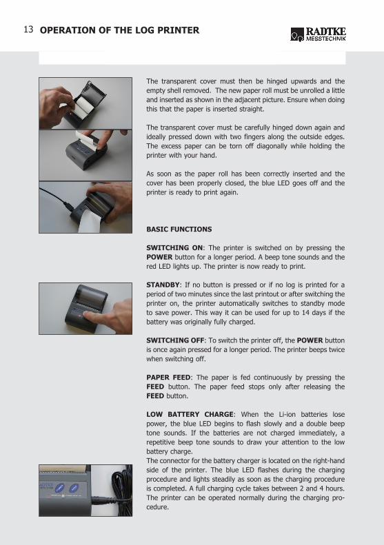
The transparent cover must then be hinged upwards and the empty shell removed. The new paper roll must be unrolled a little and inserted as shown in the adjacent picture. Ensure when doing this that the paper is inserted straight.
The transparent cover must be carefully hinged down again and ideally pressed down with two fingers along the outside edges. The excess paper can be torn off diagonally while holding the printer with your hand.
As soon as the paper roll has been correctly inserted and the cover has been properly closed, the blue LED goes off and the printer is ready to print again.
BASIC FUNCTIONS
SWITCHING ON: The printer is switched on by pressing the POWER button for a longer period. A beep tone sounds and the red LED lights up. The printer is now ready to print.
STANDBY: If no button is pressed or if no log is printed for a period of two minutes since the last printout or after switching the printer on, the printer automatically switches to standby mode to save power. This way it can be used for up to 14 days if the battery was originally fully charged.
SWITCHING OFF: To switch the printer off, the POWER button is once again pressed for a longer period. The printer beeps twice when switching off.
PAPER FEED: The paper is fed continuously by pressing the FEED button. The paper feed stops only after releasing the FEED button.
LOW BATTERY CHARGE: When the Li-ion batteries lose power, the blue LED begins to flash slowly and a double beep tone sounds. If the batteries are not charged immediately, a repetitive beep tone sounds to draw your attention to the low battery charge. The connector for the battery charger is located on the right-hand side of the printer. The blue LED flashes during the charging procedure and lights steadily as soon as the charging procedure is completed. A full charging cycle takes between 2 and 4 hours. The printer can be operated normally during the charging pro-cedure.

14
LOG PRINTOUT AFTER A CM MEASUREMENT
After each completed measurement, any number of logs can be printed out for this measurement. The respective last mea-surement remains stored until a new one has definitely begun.
The cable cover must be removed with the manometer swit-ched on (fig. 1).
Subsequently, the printer cable is seated correctly by rota-ting the plug (2-pin end with rotatable metal screw con-nection) and screwing it on lightly (fig. 2).
The printer is switched on by pressing the POWER button for a longer period. This is indicated by a beep tone and the red LED lighting up (fig. 3).
The other end of the printer cable (6-pin plug with arrow) is plugged into the left-hand side of the printer with the arrow at the top. The other hand holds the printer tight while doing this (fig. 4).
On the manometer the Print command is selected by pressing the Menu button three times and confirming within 7 seconds by pressing the Enter key (figs. 5 and 6).
This starts the flow of data and the log is printed out (fig. 7).
The log printout can be torn off the roll diagonally. The other hand holds the printer tight while doing this. (fig. 8).
In order to print several logs, the procedures starting from fig. 5 are repeated according to the number of desired logs.
INFORMATION PRINTED OUT ON THE LOG
Apart from the measuring data determined, the CM measuring log also supplies the following relevant information.
The log printout can be adapted in the factory to suit the customer’s wishes and can be individualised with logo (stored in the printer) and company address.
LOG PRINTOUT
15 LOG PRINTOUT
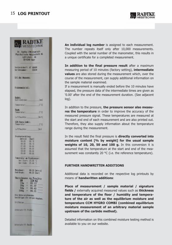
An individual log number is assigned to each measurement. The number repeats itself only after 10,000 measurements. Coupled with the serial number of the manometer, this results in a unique certificate for a completed measurement.
In addition to the final pressure result after a maximum measuring period of 10 minutes (factory setting), intermediate values are also stored during the measurement which, over the course of the measurement, can supply additional information on the sample material examined.If a measurement is manually ended before the 10 minutes have elapsed, the pressure data of the intermediate times are given as ‘0.00’ after the end of the measurement duration. (See adjacent log).
In addition to the pressure, the pressure sensor also measu-res the temperature in order to improve the accuracy of the measured pressure signal. These temperatures are measured at the start and end of each measurement and are also printed out. Therefore, they also supply information about the temperature range during the measurement.
In the result field the final pressure is directly converted into moisture content [% by weight] for the usual sample weights of 10, 20, 50 and 100 g. In this conversion it is assumed that the temperature at the start and end of the mea-surement was constantly 20 °C (i.e. the reference temperature).
FURTHER HANDWRITTEN ADDITIONS
Additional data is recorded on the respective log printouts by means of handwritten additions:
Place of measurement / sample material / signature fields / externally acquired measured values such as thickness and temperature of the floor / humidity and tempera-ture of the air as well as the equilibrium moisture and temperature CCM HYGRO COMBI (combined equilibrium moisture measurement of an arbitrary material sample upstream of the carbide method).
Detailed information on this combined moisture testing method is available to you on our website.

16 CONCLUSION
CONCLUSION
The data in the operating instructions correspond to our present level of knowledge and are intended to inform about our products as well as their application possibilities. They are not intended to assure certain characteristics of the products or their suitability for a specific purpose of use. Any existing industrial property rights are to be taken into account.We constantly strive to improve our products. Therefore we reserve the right to make changes and improvements to the products described in these operating instructions without prior notice.
DECLARATION OF CONFORMITY
European Union directives applied:We confirm that our products were manufactured in accordance with the following
directives.
• 2002/95/EC of the European Parliament and of the Council of 27/01/2003 on therestriction of the use of certain hazardous substances in electrical and electronic equipment.
• 2002/96/ECoftheEuropeanParliamentandoftheCouncilof27/01/2003onwasteelectrical and electronic equipment.
• Directive(EC)No.1907/2006(REAChregulation)oftheEuropeanParliamentandofthe Council of 18/12/2006.
• ManufacturingofthepressurebottleaccordingtothePressureEquipmentDirective97/23/ECof 29May1997on theapproximationof the lawsof themember statesconcerning pressure equipment.
• Assembly of the digital manometer (for equipment version CCM Set ECO dig dig)according to DIN EN 837-2 Pressure gauges, selection and installation recommenda-tions for pressure gauges.
• CarbideampoulesconformtothespecificationsaccordingtothelatesteditionofDIN18560-4 ‘Screeds in the construction industry’ Part 4 ‘Screeds on separating layers’, item 5.3, suitable for evaluation of readiness for covering.