Embed Size (px)
Citation preview
Operating Instructions for Aerzen Vacuum Boosters Date Doc # Page
Aerzen USA Corporation 645 Sands Court – Coatesville, PA 19320 Tel: (610) 380-0244 Fax: (610) 380-0278 www.aerzenusa.com 03/15/07RW B-4-0160 revison “A” 1 of 22
Operating Instructions for Aerzen Vacuum Boosters
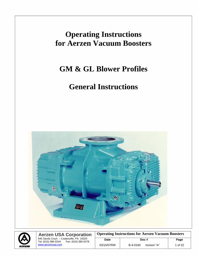
GM & GL Blower Profiles
General Instructions
Operating Instructions for Aerzen Vacuum Boosters Date Doc # Page
Aerzen USA Corporation 645 Sands Court – Coatesville, PA 19320 Tel: (610) 380-0244 Fax: (610) 380-0278 www.aerzenusa.com 03/15/07RW B-4-0160 revison “A” 2 of 22
Operating Instructions for Aerzen Vacuum Boosters
1. Safety 3 2. Construction 5 3. Principle of Operation 7 4. Flow Direction 8 5. Transportation and Storage 9 6. Installation 10 7. Maintenance 13 8. Instrumentation 20 9. Operating Limits 21 10. About Aerzen 22
Operating Instructions for Aerzen Vacuum Boosters Date Doc # Page
Aerzen USA Corporation 645 Sands Court – Coatesville, PA 19320 Tel: (610) 380-0244 Fax: (610) 380-0278 www.aerzenusa.com 03/15/07RW B-4-0160 revison “A” 3 of 22
Safety Instructions General Aerzen rotary positive displacement Vacuum Booster blowers are designed and manufactured by state of the art technique to achieve a high level of reliability and safety in operation. It is imperative, however, for safe operation that all personnel operating or maintaining the equipment read and understand the Safety and Operating Instructions before any work is performed. Any work by untrained personnel may result in danger to that person, accident or injury to that person or others and possible process equipment damage. Before operating or maintaining the equipment, all safety procedures and devices must be implemented. Safety Points No changes, which affect the safety of the equipment, may be made.
The equipment owner must ensure that only properly trained and authorized personnel may perform work on the equipment.
The equipment owner must maintain a copy of this manual and make it accessible to all personnel operating or maintaining the equipment.
A record of maintenance, safety device settings and equipment changes should be maintained and kept with this manual.
The equipment should only be operated within design parameters, when in proper mechanical condition and when all safety protocols are in effect.
The equipment should not be operated while safety devices are shut off, disconnected or out of calibration.
The area around the equipment should be safe, clean and accessible.
Only properly trained and authorized personnel may work on the electrical controls.
Discharge piping from the blower may reach a surface temperature in excess of 150 degC under some operating conditions. If high temperature operation is possible, lagging and warning signs should be provided to protect personnel.
When hazardous gasses are being conveyed:
Conveying piping may only be dismantled after being thoroughly purged with an inert gas.
The blower endbells will contain residues of the pumped process gas, even after the piping system has been purged unless special measures are taken to separately purge the endbells.
It is not safe to pump Oxygen, an Oxygen rich gas or other Strong Oxidizers with a standard machine.
Blowers prepared for “Oxygen Service” have been assembled without contamination from hydrocarbon lubricants and are tested with special PFPE chemistry lubrication. Use of other lubricating oils invalidates the “Oxygen Service” preparation.
Operating Instructions for Aerzen Vacuum Boosters Date Doc # Page
Aerzen USA Corporation 645 Sands Court – Coatesville, PA 19320 Tel: (610) 380-0244 Fax: (610) 380-0278 www.aerzenusa.com 03/15/07RW B-4-0160 revison “A” 4 of 22
Standard (hydrocarbon oil prepared) blowers may be converted use to PFPE for the purpose of resistance to process chemistry by disassembly, gross degreasing, and reassembly with PFPE oil. In this case, the blower will operate mechanically with PFPE oil but will not be prepared for “Oxygen Service”. The end user must ensure that no explosive conditions may occur within the vacuum blower due to oxygen concentration and partial pressure above normal air conditions. It is the end user’s responsibility to consult a competent engineering resource to review process safety measures if oxygen enriched gas mixtures are to be processed.
The standard vacuum blower is not intended for pumping flammable gasses. It is not spark proof and may leak process gas to the atmosphere if over pressured. Improperly maintained shaft seals may leak atmospheric air into the machine resulting in a combustible mixture. It is the end user’s responsibility to consult a competent engineering resource to review process safety measures if flammable gas mixtures are to be processed.
Pressure, or vacuum, in process piping must be relieved before breaking any connection in the piping or blower housing.
When the equipment is driven by diesel or gas engines, adequate ventilation must be provided in the operating area.
When cleaning the equipment with volatile or corrosive agents, appropriate personal protection measures must be taken to avoid injury.
Aerzen cannot assure the safety of equipment that has been modified in any way by the customer.
Additional safety and operating instructions are given in the rest of the manual.
Before returning any equipment or component to Aerzen for any reason, the user must submit a Material Hazards Declaration to the Aerzen Service Department and obtain a Return Authorization Number. A copy of the Material Hazards Declaration may be obtained by calling Aerzen USA Service (610) 380-0244.
These general precautions are meant to assist the equipment owner in formulating a safety policy regarding the equipment. The owner must conduct a safety review to determine what additional specific safety rules may be required for their particular circumstances. Spare Parts and Accessories Parts and accessories that have not been supplied by Aerzen have not passed our Quality Assurance Program. Installation and use of such components may affect the performance and safe operation of the equipment. Aerzen does not accept responsibility for the hazards or consequences resulting from the use of non-original components or accessories. Parts may be ordered using the General Repair Instruction Manual numbering system only when the serial number of the blower is also provided. To order spare parts, contact the Aerzen USA sales office at (610) 380-0244.
Operating Instructions for Aerzen Vacuum Boosters Date Doc # Page
Aerzen USA Corporation 645 Sands Court – Coatesville, PA 19320 Tel: (610) 380-0244 Fax: (610) 380-0278 www.aerzenusa.com 03/15/07RW B-4-0160 revison “A” 5 of 22
Construction of the Aerzen “HV” Vacuum Blower All components of the blower housing are mated with O-ring seals in machined grooves. O-ring sealing is
used to provide a reliable level of leak tightness. An O-ring seal is more reliable than glued or flat gasketed sealing over time and temperature cycling of the equipment. Tight sealing of housing components is critical in vacuum service for maintained pumping performance. It is also important when reactive gasses are being pumped and exclusion of air is desired. The O-ring seals are normally supplied in Viton.
Inlet and discharge flanges of the Vacuum Blower are flat faced to accommodate sealing against O-ring grooved mating flanges or flat gaskets.
The four main shaft seals are dry running,
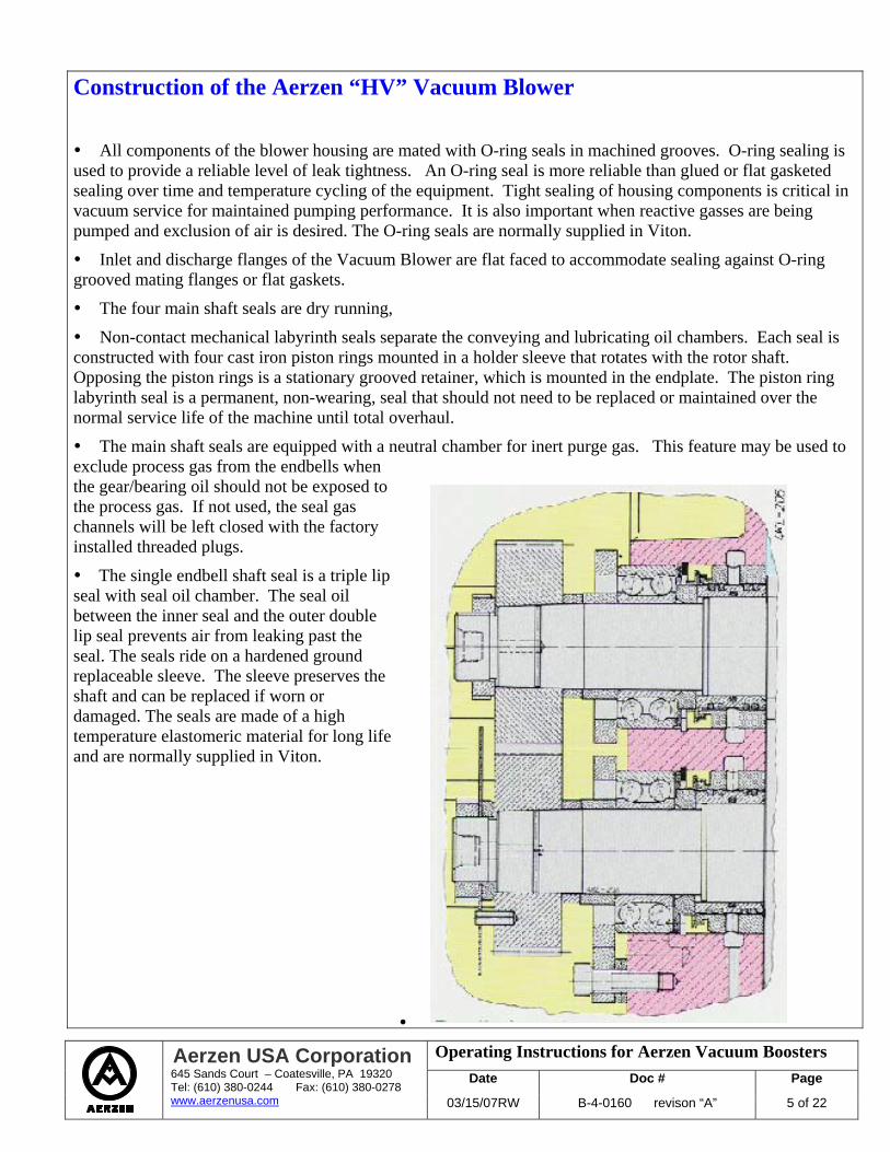
Non-contact mechanical labyrinth seals separate the conveying and lubricating oil chambers. Each seal is constructed with four cast iron piston rings mounted in a holder sleeve that rotates with the rotor shaft. Opposing the piston rings is a stationary grooved retainer, which is mounted in the endplate. The piston ring labyrinth seal is a permanent, non-wearing, seal that should not need to be replaced or maintained over the normal service life of the machine until total overhaul.
The main shaft seals are equipped with a neutral chamber for inert purge gas. This feature may be used to exclude process gas from the endbells when the gear/bearing oil should not be exposed to the process gas. If not used, the seal gas channels will be left closed with the factory installed threaded plugs.
The single endbell shaft seal is a triple lip seal with seal oil chamber. The seal oil between the inner seal and the outer double lip seal prevents air from leaking past the seal. The seals ride on a hardened ground replaceable sleeve. The sleeve preserves the shaft and can be replaced if worn or damaged. The seals are made of a high temperature elastomeric material for long life and are normally supplied in Viton.
Operating Instructions for Aerzen Vacuum Boosters Date Doc # Page
Aerzen USA Corporation 645 Sands Court – Coatesville, PA 19320 Tel: (610) 380-0244 Fax: (610) 380-0278 www.aerzenusa.com 03/15/07RW B-4-0160 revison “A” 6 of 22
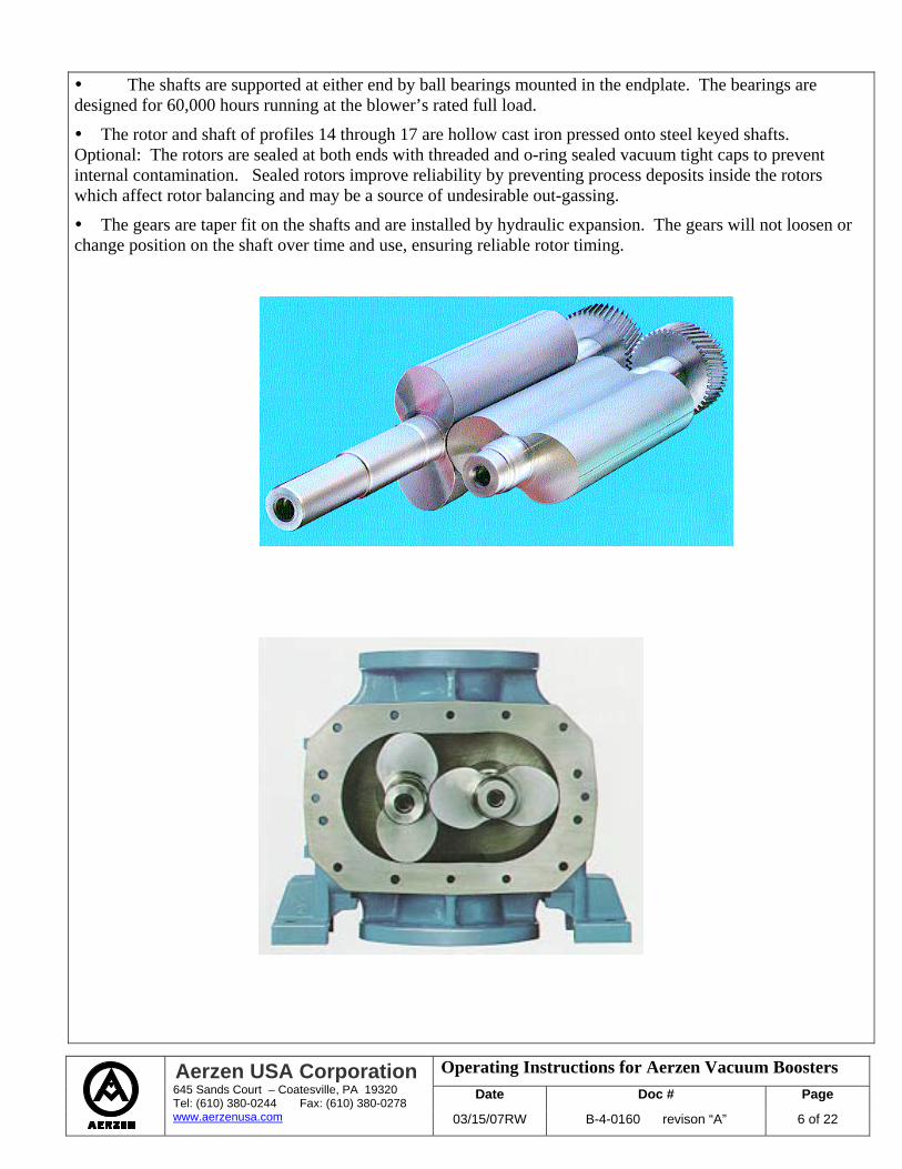
The shafts are supported at either end by ball bearings mounted in the endplate. The bearings are designed for 60,000 hours running at the blower’s rated full load.
The rotor and shaft of profiles 14 through 17 are hollow cast iron pressed onto steel keyed shafts. Optional: The rotors are sealed at both ends with threaded and o-ring sealed vacuum tight caps to prevent internal contamination. Sealed rotors improve reliability by preventing process deposits inside the rotors which affect rotor balancing and may be a source of undesirable out-gassing.
The gears are taper fit on the shafts and are installed by hydraulic expansion. The gears will not loosen or change position on the shaft over time and use, ensuring reliable rotor timing.
Operating Instructions for Aerzen Vacuum Boosters Date Doc # Page
Aerzen USA Corporation 645 Sands Court – Coatesville, PA 19320 Tel: (610) 380-0244 Fax: (610) 380-0278 www.aerzenusa.com 03/15/07RW B-4-0160 revison “A” 7 of 22
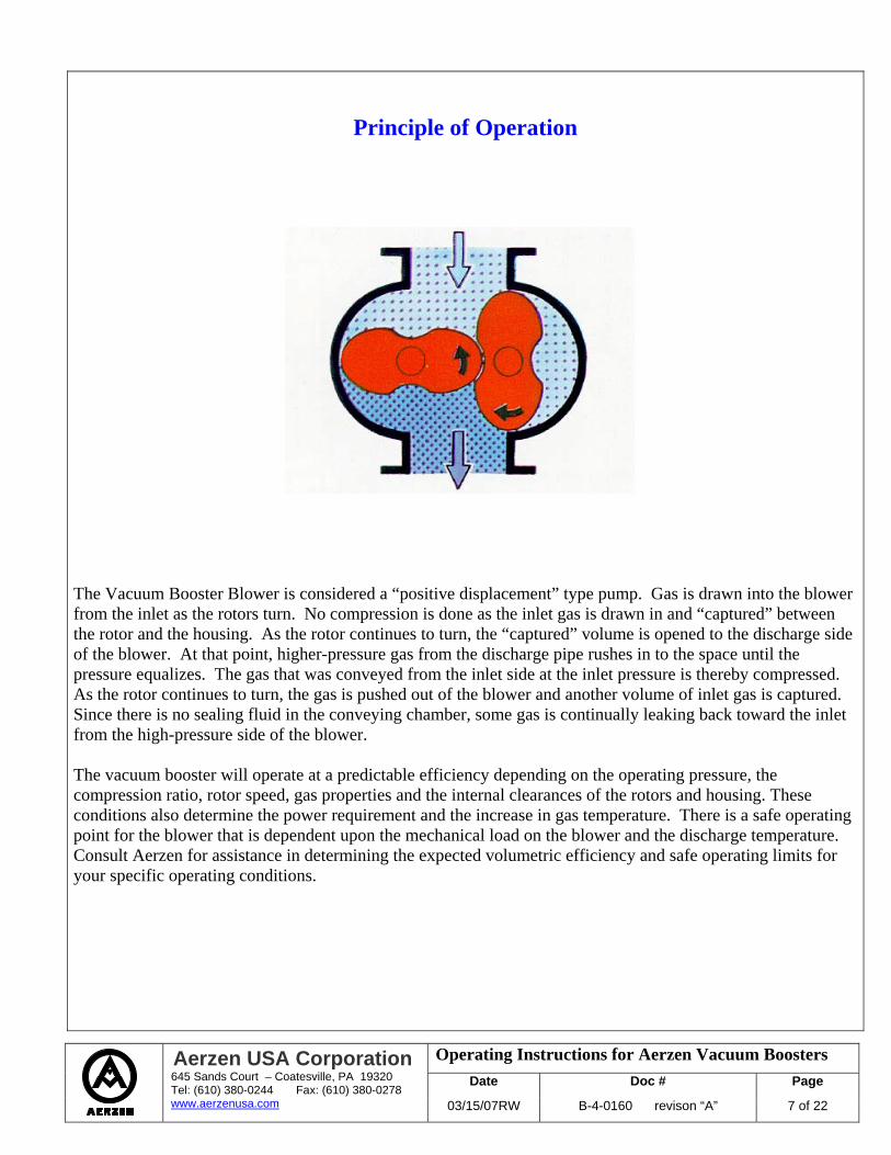
Principle of Operation The Vacuum Booster Blower is considered a “positive displacement” type pump. Gas is drawn into the blower from the inlet as the rotors turn. No compression is done as the inlet gas is drawn in and “captured” between the rotor and the housing. As the rotor continues to turn, the “captured” volume is opened to the discharge side of the blower. At that point, higher-pressure gas from the discharge pipe rushes in to the space until the pressure equalizes. The gas that was conveyed from the inlet side at the inlet pressure is thereby compressed. As the rotor continues to turn, the gas is pushed out of the blower and another volume of inlet gas is captured. Since there is no sealing fluid in the conveying chamber, some gas is continually leaking back toward the inlet from the high-pressure side of the blower. The vacuum booster will operate at a predictable efficiency depending on the operating pressure, the compression ratio, rotor speed, gas properties and the internal clearances of the rotors and housing. These conditions also determine the power requirement and the increase in gas temperature. There is a safe operating point for the blower that is dependent upon the mechanical load on the blower and the discharge temperature. Consult Aerzen for assistance in determining the expected volumetric efficiency and safe operating limits for your specific operating conditions.
Operating Instructions for Aerzen Vacuum Boosters Date Doc # Page
Aerzen USA Corporation 645 Sands Court – Coatesville, PA 19320 Tel: (610) 380-0244 Fax: (610) 380-0278 www.aerzenusa.com 03/15/07RW B-4-0160 revison “A” 8 of 22
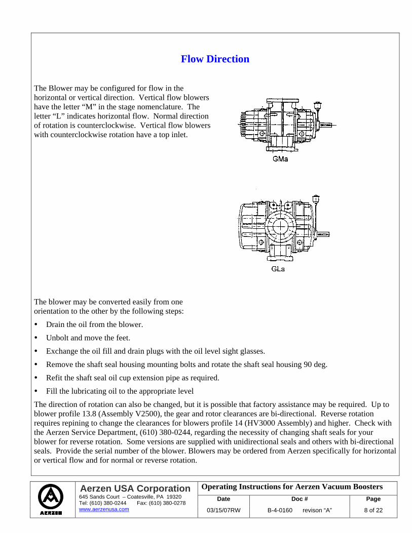
Flow Direction The Blower may be configured for flow in the horizontal or vertical direction. Vertical flow blowers have the letter “M” in the stage nomenclature. The letter “L” indicates horizontal flow. Normal direction of rotation is counterclockwise. Vertical flow blowers with counterclockwise rotation have a top inlet. The blower may be converted easily from one orientation to the other by the following steps:
Drain the oil from the blower.
Unbolt and move the feet.
Exchange the oil fill and drain plugs with the oil level sight glasses.
Remove the shaft seal housing mounting bolts and rotate the shaft seal housing 90 deg.
Refit the shaft seal oil cup extension pipe as required.
Fill the lubricating oil to the appropriate level
The direction of rotation can also be changed, but it is possible that factory assistance may be required. Up to blower profile 13.8 (Assembly V2500), the gear and rotor clearances are bi-directional. Reverse rotation requires repining to change the clearances for blowers profile 14 (HV3000 Assembly) and higher. Check with the Aerzen Service Department, (610) 380-0244, regarding the necessity of changing shaft seals for your blower for reverse rotation. Some versions are supplied with unidirectional seals and others with bi-directional seals. Provide the serial number of the blower. Blowers may be ordered from Aerzen specifically for horizontal or vertical flow and for normal or reverse rotation.
Operating Instructions for Aerzen Vacuum Boosters Date Doc # Page
Aerzen USA Corporation 645 Sands Court – Coatesville, PA 19320 Tel: (610) 380-0244 Fax: (610) 380-0278 www.aerzenusa.com 03/15/07RW B-4-0160 revison “A” 9 of 22
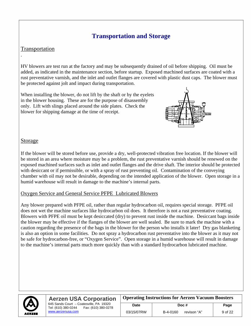
Transportation and Storage Transportation . HV blowers are test run at the factory and may be subsequently drained of oil before shipping. Oil must be added, as indicated in the maintenance section, before startup. Exposed machined surfaces are coated with a rust preventative varnish, and the inlet and outlet flanges are covered with plastic dust caps. The blower must be protected against jolt and impact during transportation. When installing the blower, do not lift by the shaft or by the eyelets in the blower housing. These are for the purpose of disassembly only. Lift with slings placed around the side plates. Check the blower for shipping damage at the time of receipt. Storage If the blower will be stored before use, provide a dry, well-protected vibration free location. If the blower will be stored in an area where moisture may be a problem, the rust preventative varnish should be renewed on the exposed machined surfaces such as inlet and outlet flanges and the drive shaft. The interior should be protected with desiccant or if permissible, or with a spray of rust preventing oil. Contamination of the conveying chamber with oil may not be desirable, depending on the intended application of the blower. Open storage in a humid warehouse will result in damage to the machine’s internal parts. Oxygen Service and General Service PFPE Lubricated Blowers Any blower prepared with PFPE oil, rather than regular hydrocarbon oil, requires special storage. PFPE oil does not wet the machine surfaces like hydrocarbon oil does. It therefore is not a rust preventative coating. Blowers with PFPE oil must be kept desiccated (dry) to prevent rust inside the machine. Desiccant bags inside the blower may be effective if the flanges of the blower are well sealed. Be sure to mark the machine with a caution regarding the presence of the bags in the blower for the person who installs it later! Dry gas blanketing is also an option in some facilities. Do not spray a hydrocarbon rust preventative into the blower as it may not be safe for hydrocarbon-free, or “Oxygen Service”. Open storage in a humid warehouse will result in damage to the machine’s internal parts much more quickly than with a standard hydrocarbon lubricated machine.
Operating Instructions for Aerzen Vacuum Boosters Date Doc # Page
Aerzen USA Corporation 645 Sands Court – Coatesville, PA 19320 Tel: (610) 380-0244 Fax: (610) 380-0278 www.aerzenusa.com 03/15/07RW B-4-0160 revison “A” 10 of 22
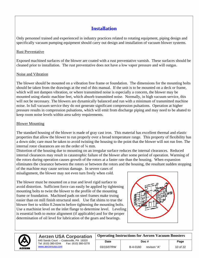
Installation Only personnel trained and experienced in industry practices related to rotating equipment, piping design and specifically vacuum pumping equipment should carry out design and installation of vacuum blower systems. Rust Preventative Exposed machined surfaces of the blower are coated with a rust preventative varnish. These surfaces should be cleaned prior to installation. The rust preventative does not have a low vapor pressure and will outgas. Noise and Vibration The blower should be mounted on a vibration free frame or foundation. The dimensions for the mounting bolts should be taken from the drawings at the end of this manual. If the unit is to be mounted on a deck or frame, which will not dampen vibration, or where transmitted noise is especially a concern, the blower may be mounted using elastic machine feet, which absorb transmitted noise. Normally, in high vacuum service, this will not be necessary. The blowers are dynamically balanced and run with a minimum of transmitted machine noise. In full vacuum service they do not generate significant compression pulsations. Operation at higher pressure results in compression pulsations, which will emit from discharge piping and may need to be abated to keep room noise levels within area safety requirements. Blower Mounting The standard housing of the blower is made of gray cast iron. This material has excellent thermal and elastic properties that allow the blower to run properly over a broad temperature range. This property of flexibility has a down side; care must be taken to avoid twisting the housing to the point that the blower will not run free. The internal rotor clearances are on the order of ¼ mm. Distortion of the housing due to mounting on an irregular surface reduces the internal clearances. Reduced internal clearances may result in catastrophic failure of the blower after some period of operation. Warming of the rotors during operation causes growth of the rotors at a faster rate than the housing. When expansion eliminates the clearance between the rotors or between the rotors and the housing, the resultant sudden stopping of the machine may cause serious damage. In severe cases of misalignment, the blower may not even turn freely when cold. The blower must be mounted on a true and level rigid surface to avoid distortion. Sufficient force can easily be applied by tightening mounting bolts to twist the blower to the profile of the mounting frame or foundation. Machined pads on steel frames make truing easier than on mill finish structural steel. Use flat shims to true the blower feet to within 0.2mm/m before tightening the mounting bolts. Use a machinist level on the inlet flange to determine level. Leveling is essential both to motor alignment (if applicable) and for the proper determination of oil level for lubrication of the gears and bearings.
Operating Instructions for Aerzen Vacuum Boosters Date Doc # Page
Aerzen USA Corporation 645 Sands Court – Coatesville, PA 19320 Tel: (610) 380-0244 Fax: (610) 380-0278 www.aerzenusa.com 03/15/07RW B-4-0160 revison “A” 11 of 22
Anchoring After leveling is accomplished, the anchor bolts should be tightened. On blower sizes with four independent feet (profiles 18 and higher), only the drive side feet should be tightly bolted down. The two feet on the end opposite the drive shaft should be fixed with washer plates under the bolt heads to allow minor movement due to thermal expansion. Blowers, profiles up to 17, may be tightened at all four anchoring positions. After the anchor bolts have been tightened, it should be possible to turn the shaft easily by hand. Check for soft foot conditions. Shim where necessary. Recheck the shims under the blower feet for anchoring stress that may have distorted the housing. Maximum allowable gap under foot mount is 2/1000”. Resistance to turning could also be due to foreign material having fallen inside the blower. Motor Alignment If the blower is equipped with a motor adapter flange for close coupling of a c-face motor, then alignment of the motor is automatic. Inspection of the motor c-face mounting and motor adapter flange mounting to the blower housing should be done to verify parallel mating faces. Spacing of the drive coupling should be per the manufacturer’s specifications. For base mounted motors refer to the maintenance section of this manual. Couplings and Pulleys The drive shaft should be cleaned of all rust preventative varnish or oil before fitting pulleys or couplings. Installation and later removal of the pulley or coupling are easier if the shaft is first lubricated with molybdenum disulfide (e.g.; Molykote). Only couplings, which have been machined on all sides and balanced for the appropriate rpm, should be used. Direct drive units supplied with C-face motor are normally provided with KTR Rotex / Lovejoy style couplings. If installing your own coupling, follow the coupling manufacturer’s installation instructions carefully. Pipe Connections Careful design and installation of connecting piping is critical for the reasons discussed under Blower Mounting above. Hard pipe connections to the inlet and outlet blower flanges must be avoided. Care must be taken to avoid blower housing distortion problems. Consider that if the blower feet are securely fixed, and the blower inlet or discharge flange is drawn up to a misaligned pipe connection, both the pipe and the blower will be under deformation forces. If the pipe wins in this tug of war, the blower can be severely damaged. Thermal expansion of pipe during operation of the process can cause significant dimensional changes. The weight of pipe or accessories supported by the pipe at some distance from the blower can cause significant moment arm forces on the blower flange as well. The distortion effects of pipe connection stress affect the safe operating limits of the blower. In some cases, blower failure occurs due to these effects after hours of operation, even at “no load”.
Operating Instructions for Aerzen Vacuum Boosters Date Doc # Page
Aerzen USA Corporation 645 Sands Court – Coatesville, PA 19320 Tel: (610) 380-0244 Fax: (610) 380-0278 www.aerzenusa.com 03/15/07RW B-4-0160 revison “A” 12 of 22
Expansion Joints The safest way to protect the blower from mechanical distortion forces is to install expansion joints at the inlet and outlet flange of the blower. Alignment recommendations of the expansion joint manufacturer should be adhered to. If corrugated steel expansion joints are used, take care not to stretch or misalign the expansion joint beyond the manufacturer’s recommendation. Extension of the joint by ¼ inch is normally allowed. Horizontal distortion may result in expansion joint failure (leak). Pipe elbows may be installed between the blower and the expansion joint. If this is required, the pipe elbow must be supported only by the blower, and not additionally anchored to some other fixed object such as frame or building. Lengths of pipe should not be cantilevered from the blower flange. Flange Mounting of the Blower The blower may be mounted directly to process vessels or pipe by the inlet or discharge flange up to profile 15. If this is done, the motor must be c-face mounted to the blower and the feet of the blower must not be bolted to any base or support. The feet can be removed from the blower to improve the appearance of this type of installation. If the blower is flange mounted, an expansion joint must connect the flange at the opposite side of the blower to downstream piping. The blower must still be level for the gear and bearing lubrication to function properly. Check Rotation After mounting the blower and wiring the motor, check the direction of rotation. Standard rotation is counter clockwise. Check the installation documentation to determine the intended blower inlet orientation and direction of flow. Check the “Principle of Operation” section of this manual to learn which direction of rotation corresponds to the intended blower orientation. Rotation must match the arrows applied to the blower by the factory. It is not necessary to decouple the motor from the blower to “jog” it. Do not run HV blowers in the wrong rotation for more than the 2 seconds required to verify (jog) motor wiring connections in a blocked section of pipe with air in the system. Back pressure can develop that might exceed the mechanical load limits of the blower or motor and will also force the blower to spin back in the opposite direction when the motor is turned off. It is recommended to run the downstream vacuum pump until the line is evacuated and then turn the blower on (or jog it) to check rotation. Leak Checking Leak Check the entire vacuum system prior to startup of the blower. In-leakage of atmospheric air can cause overheating of the blower or significantly reduce the performance of the blower. Total in-leakage of air can be measured by a rate of rise measurement, which involves isolating the vacuum equipment with the pumps off and measuring the pressure rise over time. The overall rate of rise should be equivalent to a small percentage of the blower capacity at the intended operating pressure. Do not leak check vacuum blowers with compressed gas or shaft seal failure may result. Do not hydro-test vacuum blowers. Hydro-testing is done at the factory (if requested) before final assembly only.
Operating Instructions for Aerzen Vacuum Boosters Date Doc # Page
Aerzen USA Corporation 645 Sands Court – Coatesville, PA 19320 Tel: (610) 380-0244 Fax: (610) 380-0278 www.aerzenusa.com 03/15/07RW B-4-0160 revison “A” 13 of 22
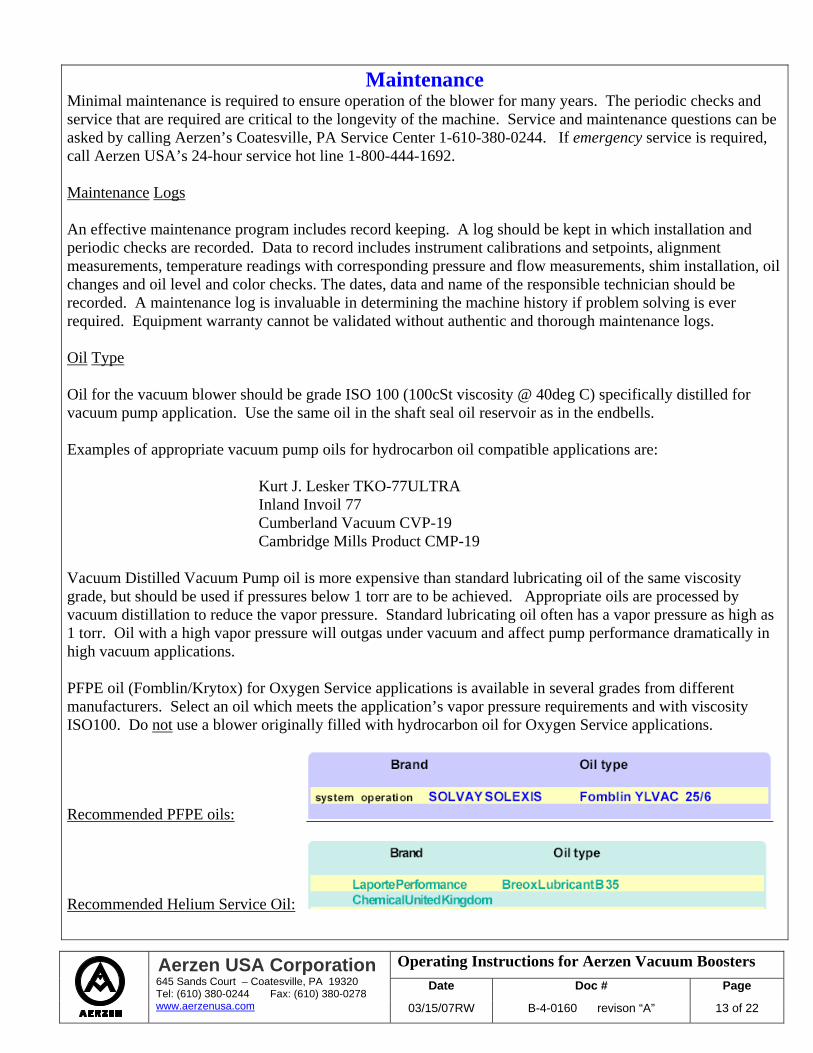
Maintenance Minimal maintenance is required to ensure operation of the blower for many years. The periodic checks and service that are required are critical to the longevity of the machine. Service and maintenance questions can be asked by calling Aerzen’s Coatesville, PA Service Center 1-610-380-0244. If emergency service is required, call Aerzen USA’s 24-hour service hot line 1-800-444-1692. Maintenance Logs An effective maintenance program includes record keeping. A log should be kept in which installation and periodic checks are recorded. Data to record includes instrument calibrations and setpoints, alignment measurements, temperature readings with corresponding pressure and flow measurements, shim installation, oil changes and oil level and color checks. The dates, data and name of the responsible technician should be recorded. A maintenance log is invaluable in determining the machine history if problem solving is ever required. Equipment warranty cannot be validated without authentic and thorough maintenance logs. Oil Type Oil for the vacuum blower should be grade ISO 100 (100cSt viscosity @ 40deg C) specifically distilled for vacuum pump application. Use the same oil in the shaft seal oil reservoir as in the endbells. Examples of appropriate vacuum pump oils for hydrocarbon oil compatible applications are: Kurt J. Lesker TKO-77ULTRA Inland Invoil 77 Cumberland Vacuum CVP-19 Cambridge Mills Product CMP-19 Vacuum Distilled Vacuum Pump oil is more expensive than standard lubricating oil of the same viscosity grade, but should be used if pressures below 1 torr are to be achieved. Appropriate oils are processed by vacuum distillation to reduce the vapor pressure. Standard lubricating oil often has a vapor pressure as high as 1 torr. Oil with a high vapor pressure will outgas under vacuum and affect pump performance dramatically in high vacuum applications. PFPE oil (Fomblin/Krytox) for Oxygen Service applications is available in several grades from different manufacturers. Select an oil which meets the application’s vapor pressure requirements and with viscosity ISO100. Do not use a blower originally filled with hydrocarbon oil for Oxygen Service applications.
Recommended PFPE oils:
Recommended Helium Service Oil:
Operating Instructions for Aerzen Vacuum Boosters Date Doc # Page
Aerzen USA Corporation 645 Sands Court – Coatesville, PA 19320 Tel: (610) 380-0244 Fax: (610) 380-0278 www.aerzenusa.com 03/15/07RW B-4-0160 revison “A” 14 of 22
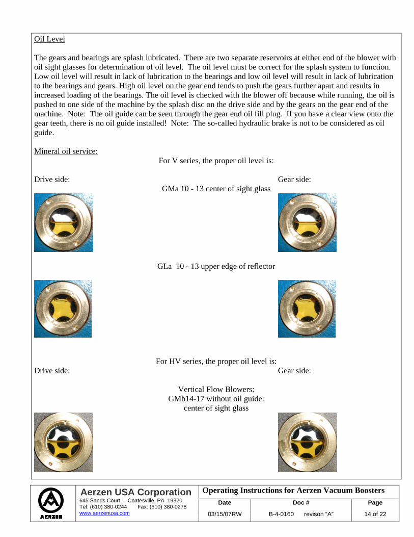
Oil Level The gears and bearings are splash lubricated. There are two separate reservoirs at either end of the blower with oil sight glasses for determination of oil level. The oil level must be correct for the splash system to function. Low oil level will result in lack of lubrication to the bearings and low oil level will result in lack of lubrication to the bearings and gears. High oil level on the gear end tends to push the gears further apart and results in increased loading of the bearings. The oil level is checked with the blower off because while running, the oil is pushed to one side of the machine by the splash disc on the drive side and by the gears on the gear end of the machine. Note: The oil guide can be seen through the gear end oil fill plug. If you have a clear view onto the gear teeth, there is no oil guide installed! Note: The so-called hydraulic brake is not to be considered as oil guide. Mineral oil service:
For V series, the proper oil level is: Drive side: Gear side:
GMa 10 - 13 center of sight glass
GLa 10 - 13 upper edge of reflector
For HV series, the proper oil level is: Drive side: Gear side:
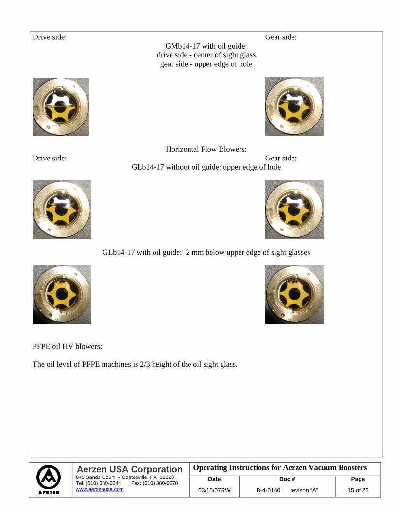
Vertical Flow Blowers: GMb14-17 without oil guide:
center of sight glass
Operating Instructions for Aerzen Vacuum Boosters Date Doc # Page
Aerzen USA Corporation 645 Sands Court – Coatesville, PA 19320 Tel: (610) 380-0244 Fax: (610) 380-0278 www.aerzenusa.com 03/15/07RW B-4-0160 revison “A” 15 of 22
Drive side: Gear side: GMb14-17 with oil guide:
drive side - center of sight glass gear side - upper edge of hole
Horizontal Flow Blowers: Drive side: Gear side:
GLb14-17 without oil guide: upper edge of hole
GLb14-17 with oil guide: 2 mm below upper edge of sight glasses
PFPE oil HV blowers: The oil level of PFPE machines is 2/3 height of the oil sight glass.
Operating Instructions for Aerzen Vacuum Boosters Date Doc # Page
Aerzen USA Corporation 645 Sands Court – Coatesville, PA 19320 Tel: (610) 380-0244 Fax: (610) 380-0278 www.aerzenusa.com 03/15/07RW B-4-0160 revison “A” 16 of 22
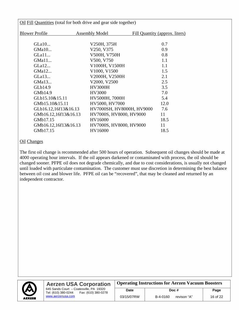
Oil Fill Quantities (total for both drive and gear side together) Blower Profile Assembly Model Fill Quantity (approx. liters) GLa10... V250H, 375H 0.7 GMa10... V250, V375 0.9 GLa11... V500H, V750H 0.8 GMa11... V500, V750 1.1 GLa12... V1000H, V1500H 1.1
GMa12... V1000, V1500 1.5 GLa13... V2000H, V2500H 2.1 GMa13... V2000, V2500 2.5 GLb14.9 HV3000H 3.5 GMb14.9 HV3000 7.0 GLb15.10&15.11 HV5000H, 7000H 5.4 GMb15.10&15.11 HV5000, HV7000 12.0 GLb16.12,16f13&16.13 HV7000SH, HV8000H, HV9000 7.6 GMb16.12,16f13&16.13 HV7000S, HV8000, HV9000 11 GMb17.15 HV16000 18.5 GMb16.12,16f13&16.13 HV7000S, HV8000, HV9000 11 GMb17.15 HV16000 18.5 Oil Changes The first oil change is recommended after 500 hours of operation. Subsequent oil changes should be made at 4000 operating hour intervals. If the oil appears darkened or contaminated with process, the oil should be changed sooner. PFPE oil does not degrade chemically, and due to cost considerations, is usually not changed until loaded with particulate contamination. The customer must use discretion in determining the best balance between oil cost and blower life. PFPE oil can be “recovered”, that may be cleaned and returned by an independent contractor.
Operating Instructions for Aerzen Vacuum Boosters Date Doc # Page
Aerzen USA Corporation 645 Sands Court – Coatesville, PA 19320 Tel: (610) 380-0244 Fax: (610) 380-0278 www.aerzenusa.com 03/15/07RW B-4-0160 revison “A” 17 of 22
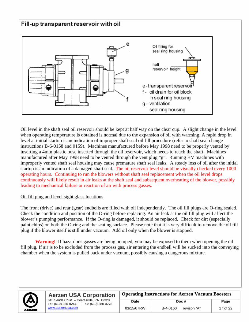
Oil level in the shaft seal oil reservoir should be kept at half way on the clear cup. A slight change in the level when operating temperature is obtained is normal due to the expansion of oil with warming. A rapid drop in level at initial startup is an indication of improper shaft seal oil fill procedure (refer to shaft seal change instructions B-6-0158 and 0159). Machines manufactured before May 1998 need to be properly vented by inserting a 4mm plastic hose inserted through the oil reservoir, which needs to reach the shaft. Machines manufactured after May 1998 need to be vented through the vent plug “g”. Running HV machines with improperly vented shaft seal housing may cause premature shaft seal leaks. A steady loss of oil after the initial startup is an indication of a damaged shaft seal. The oil reservoir level should be visually checked every 1000 operating hours. Continuing to run the blowers without shaft seal replacement when the oil level drops continuously will likely result in air leaks at the shaft seal and subsequent overheating of the blower, possibly leading to mechanical failure or reaction of air with process gasses. Oil fill plug and level sight glass locations The front (drive) and rear (gear) endbells are filled with oil independently. The oil fill plugs are O-ring sealed. Check the condition and position of the O-ring before replacing. An air leak at the oil fill plug will affect the blower’s pumping performance. If the O-ring is damaged, it should be replaced. Check for dirt (especially paint chips) on both the O-ring and the seating surface. Please note that it is very difficult to remove the oil fill plug if the blower itself is still under vacuum. Add oil only when the blower is stopped.
Warning! If hazardous gasses are being pumped, you may be exposed to them when opening the oil fill plug. If air is to be excluded from the process gas, air entering the endbell will be sucked into the conveying chamber when the system is pulled back under vacuum, possibly causing a dangerous mixture.
Operating Instructions for Aerzen Vacuum Boosters Date Doc # Page
Aerzen USA Corporation 645 Sands Court – Coatesville, PA 19320 Tel: (610) 380-0244 Fax: (610) 380-0278 www.aerzenusa.com 03/15/07RW B-4-0160 revison “A” 18 of 22
Drive Coupling
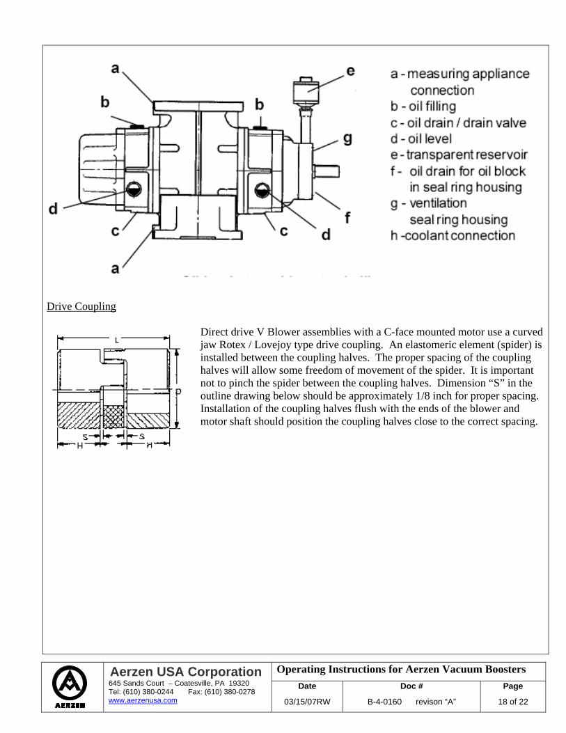
Direct drive V Blower assemblies with a C-face mounted motor use a curved jaw Rotex / Lovejoy type drive coupling. An elastomeric element (spider) is installed between the coupling halves. The proper spacing of the coupling halves will allow some freedom of movement of the spider. It is important not to pinch the spider between the coupling halves. Dimension “S” in the outline drawing below should be approximately 1/8 inch for proper spacing. Installation of the coupling halves flush with the ends of the blower and motor shaft should position the coupling halves close to the correct spacing.
Operating Instructions for Aerzen Vacuum Boosters Date Doc # Page
Aerzen USA Corporation 645 Sands Court – Coatesville, PA 19320 Tel: (610) 380-0244 Fax: (610) 380-0278 www.aerzenusa.com 03/15/07RW B-4-0160 revison “A” 19 of 22
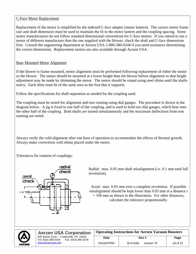
C-Face Motor Replacement Replacement of the motor is simplified by the indexed C-face adapter (motor lantern). The correct motor frame size and shaft dimension must be used to maintain the fit to the motor lantern and the coupling spacing. Some motor manufacturers do not follow standard dimensional conventions for C-face motors. If you intend to use a motor of different manufacture than the one supplied with the blower, check the shaft and C-face dimensions first. Consult the engineering department at Aerzen USA 1-800-380-0244 if you need assistance determining the correct dimensions. Replacement motors are also available through Aerzen USA. Base Mounted Motor Alignment If the blower is frame mounted, motor alignment must be performed following replacement of either the motor or the blower. The motor should be mounted at a lower height than the blower before alignment so that height adjustment may be made by shimming the motor. The motor should be raised using steel shims until the shafts marry. Each shim must be of the same area as the foot that it supports. Follow the specifications for shaft separation as needed for the coupling used. The coupling must be tested for alignment and true running using dial gauges. The procedure is shown in the diagram below. A jig is fixed to one half of the coupling, and is used to hold two dial gauges, which bear onto the other half of the coupling. Both shafts are turned simultaneously and the maximum deflections from true running are noted. Always verify the cold alignment after one hour of operation to accommodate the effects of thermal growth. Always make corrections with shims placed under the motor. Tolerances for rotation of couplings:
Radial: max. 0.05 mm shaft misalignment (i.e. 0.1 mm total full revolution).
Axial: max. 0.05 mm over a complete revolution. If possible misalignment should be kept lower than 0.03 mm at a distance r
= 100 mm as shown in the illustration. For other distances, calculate the tolerance proportionally.
Operating Instructions for Aerzen Vacuum Boosters Date Doc # Page
Aerzen USA Corporation 645 Sands Court – Coatesville, PA 19320 Tel: (610) 380-0244 Fax: (610) 380-0278 www.aerzenusa.com 03/15/07RW B-4-0160 revison “A” 20 of 22
Instrumentation The Aerzen vacuum blower is normally not supplied with instrumentation. Instrumentation is required for direct drive units to protect the blower from operating over its safety limit. The basic instrumentation required includes a pressure switch and a temperature switch. Install the pressure switch on the inlet of the blower or the first stage blower on multiple stage systems. Install the temperature switch on the discharge side of each blower. The location of the temperature switch sensor is critical. The sensor must be placed in the gas stream as closely to the discharge side of the rotors as possible. A thermocouple is preferred. A switch embedded in the pipe or mounted on the outside of the blower housing is not adequate. Settings for the switches may be determined using the “Operating Limits” section of this manual. Determine the normal operating temperature for the application. Determine the “safety limit” temperature for the blower indicated in the “Operating Limits”. Determine the “accuracy” of the temperature sensor by consulting the documentation or the manufacturer of the instrument. Set the High Temperature Switch Point midway between the normal operating point and the safety limit, less the sensor accuracy. The pressure switch must be an absolute pressure switch. An absolute pressure switch measures the difference between the actual pressure and a relatively “absolute” vacuum. Switches or gauges, which measure pressure relative to atmospheric pressure, are inexpensive, but unacceptable as switches for vacuum blowers. Atmospheric pressure varies from day to day with the weather. These changes in “barometric” pressure are greater than the tolerance required for setting the switch to protect the vacuum blower. Select an instrument that is designed to indicate the desired setpoint pressure in the center 80% of the instrument’s range. Set the pressure switch at the lower of; the pressure corresponding to the temperature switch setting, or the pressure corresponding to the blower power limit. Instrument documentation should be kept on file with this operating manual, along with calibration and maintenance records. Failure to properly instrument the blower, or failure to calibrate and maintain the instrumentation with appropriate record keeping voids all warranties for the equipment.
Operating Instructions for Aerzen Vacuum Boosters Date Doc # Page
Aerzen USA Corporation 645 Sands Court – Coatesville, PA 19320 Tel: (610) 380-0244 Fax: (610) 380-0278 www.aerzenusa.com 03/15/07RW B-4-0160 revison “A” 21 of 22
Operating Limits Thermal Limit The “thermal limit” is the estimated operating point at which failure is expected to occur due to thermal overloading of the blower. It is the point at which the rotors will expand sufficiently to contact each other and/or the blower housing. Under vacuum, compressed gas follows the same laws of thermodynamics regarding heat of compression as does gas at elevated pressures. Temperature rise depends upon compression ratio and not inlet pressure. At a compression ratio of 2:1, temperature rise during compression will not exceed blower discharge temperature limits as long as the inlet temperature is below 100 deg F and the ambient temperature is near normal. Compression ratios exceeding 2:1 require careful thermodynamic calculation during the equipment selection process to ensure backing stages are adequately sized, and reliable instrumentation must be installed to prevent excursions beyond design conditions. At the lower end of the rough vacuum region, heat transferred to the blower rotors by the gas is lost to the surroundings by radiation between the rotors and the housing. At some pressure, the gas density is low enough that the heat transferred to the rotors by the gas cannot exceed the rate at which heat can be lost to the housing by radiation. Below this pressure, thermal limits do not need to be considered. Thermal limits generally do not apply when the discharge pressure of the blower is below 1 torr. The specific pressure at which a thermal limit must be considered varies with the size and rpm of the blower. Mechanical limit The mechanical limit of the blower is a function of the pressure difference across the blower and the rpm. Unless the motor power limitations of the blower are exceeded, the mechanical limit is essentially the motor power limit. The mechanical limit is the point at which the blower may be started as the process equipment is evacuated from atmosphere. Both the thermal and mechanical limits are based on ideal operating conditions. Failure to mount the blower without housing stress or distortion will reduce the safe operating limits of the blower. Higher than anticipated inlet gas temperature or elevated ambient temperature may also lower the thermal limit. Changing the gas composition will also change the heat of compression realized. Often, many hours of operation will pass before a blower operating in vacuum will reach an equilibrium temperature, so that failures due to thermal excess occur after some prolonged period of operation.
Operating Instructions for Aerzen Vacuum Boosters Date Doc # Page
Aerzen USA Corporation 645 Sands Court – Coatesville, PA 19320 Tel: (610) 380-0244 Fax: (610) 380-0278 www.aerzenusa.com 03/15/07RW B-4-0160 revison “A” 22 of 22
About Aerzen Aerzen Maschinenfabrik is located in Aerzen, Germany, near the city of Hameln. Aerzen is one of the world’s largest and oldest manufacturers of rotary lobe blowers and rotary screw compressors. Manufacturing of rotary piston blowers began at the Aerzen foundry in 1868. The foundry was already well established at that time in the manufacture of farm equipment and other cast iron products. Manufacturing has continued at the same site since that time. The appearance of blower systems has changed somewhat over the decades, but Aerzen’s tradition of designing and manufacturing quality and reliability have remained a constant. Aerzen developed the first high vacuum booster blowers in the industry in the early 1900’s for use in the emerging technology of vacuum metallurgy. We have since been a supplier to the world’s leading vacuum furnace manufacturers, thin film coating equipment builders, vacuum pump manufacturers and chemical process industries. Aerzen has manufactured over 500,000 blowers and has one of the largest installed bases of such equipment. Our factory is also one of the most modern flexible machining facilities for blower manufacture. Aerzen’s long experience, combined with an efficient manufacturing facility, tradition of craftsmanship and dedication to customer service result in a product that is recognized as the best value, highest quality blower on the market.